PFPE lubrication performance

合集下载

全氟聚醚润滑脂

全氟聚醚润滑脂

PFPE Lubricating GreaseDr. Martin Schweigkofler, Dr. Stefan Grundei, Dr. Wallace Zhang, Jocelyn ZhaoDr. Thomas Kilthau, Dr. Martin Schmidt-Amelunxen, Dr. Stefan Seemeyer,Klüber Lubrication München SE & Co. KGKlüber Lubrication Industries (Shanghai) Co.,Ltd.AbstractThe paper discloses lubricating greases which contain perfluoropolyether. Composition1.PFPE oilLubrication greases use base oils like mineral oils, native oils, and synthetic hydrocarbon oils, such as PAO, alkylated naphthalines, alkylated phenylethers, silicone oils, ester oils, polyglycols and so on. All these base oils contain hydrogen bonded to Carbon, i.e. CH, CH2 and CH3 groups. These base oils cannot be used at very high temperatures and can react with different chemicals like oxidizing materials. Some of them are not sufficiently stable against hydrolysis or nucleophilic substances, e.g. amines. These hydrocarbon oils can also have a strong undesired impact on seal materials or components made out of plastics such as POM, Polyamides and PEEK.These weakness can be minimized or avoided by using Perfluoropolyether (PFPE) of the general formulaX´O(CF2O)m(CF2CF2O)n[CF2CF(CF3)O]s [CF(CF3)O]u(CF2CF2CF2O)v X (I)As base oil or part of the base oil.In drawing (I) the perfluoroalkyloxy units can be distributed randomly throughout the chain. The subscripts m, n, s, u, and v can independently be 0 to maximal 200. The molecular weight of the material for example determined by the ratio of the terminal groups compared to the internal groups via NMR analysis can be up to 20000 u.The kinematic viscosity of the perfluoropolyether can be between 5 and 2000 mm²/sec at 40°C, more preferable between 15 and 1300 mm²/sec.The pour point of the perfluoropolyether can be as low as – 80°C.The end groups X and X´ can be can be short chain perfluoroalkyl groups like CF3, C2F5, C3F7,fluorine groups is substituted by a hydrocarbon group, hydrogen, hydroxyl groups, amine groups, amid groups, carbonyl groups, or other functional groups.2.PFPE based greaseTypical PFPE lubricating grease is composed by base oil and thickener. In some PFPE grease, one or more additives are added as well.The NLGI class of the greases can be between 000 and 5, preferred between 0 and 3, even more preferred between 1 and 3.a)Base oili.Pure PFPE base oilThe perfluoropolyether can be used alone or in mixtures of two or more of the possibletypes as indicated by formula I.ii.Hybrid base oilThe base oil can be also composed by one or more type perfluoropolyether, mixed with one or more from the following type oil: mineral oils, synthetic oils or native oils. Typical ratio of PFPE to the other oils is in the range of 1:10 to 10:1.The synthetic oils are selected from an ester of an aliphatic or aromatic di-, tri- ortetracarboxylic acid with one or a mixture of C7 to C22 alcohols, a polyphenyl ether oralkylated diphenyl ether, an ester of trimethylolpropane, pentaerythritol or dipentaerythritol with aliphatic C7 to C22 carboxylic acids, C18 dimer acid esters with C7 to C22 alcohols, complex esters, individual components or in any mixtures. In addition, the synthetic oil may beselected from poly-α-olefins, metallocene catalyzed PAO, alkylated naphthalenes, alkylated benzenes, polyglycols, silicone oils, or alkylated diphenylether.The mineral oils may be selected from paraffin-basic, naphthene-basic, aromatichydrocracking oils; gas to liquid (GTL) liquids, GTL refers to a gas to liquid method anddescribes a method for production of fuel from natural gas. Natural gas is converted bysteam reforming to synthesis gas, which is then converted by Fischer-Tropsch synthesis to fuels by using catalysts. The catalysts and the process conditions control the type of fuel, i.e., whether gasoline, kerosene, diesel or oils are produced. Coal may also be used as a rawmaterial in the same way by the coal to liquid method (CTL) and biomass may be used as a raw material in the biomass to liquid (BTL) method.Triglycerides from animal/vegetable sources that have been upgraded by known methods such as hydrogenation may be used as native oils. The especially preferred triglyceride oils are genetically modified triglyceride oils with high oleic acid content. Typical vegetable oils used therein and genetically modified or cultured having a high oil content include safflower oil, corn oil, canola oil, sunflower oil, soybean oil, linseed oil, peanut oil, lesquerella oil,meadowfoam oil and palm oil. The native oils might further be processed e.g. polymerization processes.b)thickenerThe thickener material used can be fluorinated polymers like polytetrafluoroethylene (PTFE), oxides like silica, organic carbonic acid salts, boron nitride, carbides like silicon carbide, poly- or diurea compounds, polyimides or polyamidimides, melamine cyanurates, graphite, carbon black, carbon nanotubes, molybdates, phosphates.The PTFE used can be produced by polymerization of tetrafluorethylene in suspension or dispersion. To adjust the particle size and the polymer chain length processes like grinding, thermal treatment or irradiation processes can be used. PTFE powders treated as indicated above are e.g. known as micronized PTFE, but also dispersion processes leading to lowmolecular weight PTFE are known. These PTFE products can be used without the processes indicated above.Typical molecular weights are between 10000 g/mol and 10exp8 g/mol, preferred between 100000 g/mol and 10exp7 g/mol.Also recycling of PTFE by processes as indicated above can produce PTFE powders that can be used for thickeners of lubricants.The organic acids can be saturated or unsaturated, branched or unbranched, mono or di or tri or polyacids containing 6 to 25 carbon acids and their mixtures like stearic acid,hydroxystearic acid, benzoic acid, oleic acid, acelaic acid, sebacic acids, behenic acid, amid groups containing acids. Amid group containing acids can for example be prepared byreacting primary or secondary aliphatic amines with di-acids or di-esters of aliphatic oraromatic carbonic acids.The cations of the organic acid salts can be lithium, sodium, potassium, magnesium, calcium, aluminum, barium or zinc.The urea compounds are reaction products of aliphatic or aromatic mono or diisocyanatemixtures. Examples for suitable urea compounds are reaction products of diisocyanates, preferably 2,4-diisocyanatotoluene, 2,6-diisocyanatotoluene,4,4′-diisocyanatodiphenylmethane, 2,4′-diisocyanatodiphenylmethane,4,4′-diisocyanatodiphenyl, 4,4′-diisocyanato-3,3′-dimethyldiphenyl,4,4′-diisocyanato-3,3′-dimethylphenylmethane which may be used individually or incombination, with an amine of the general formula R′2N—R or a diamine of the generalformula R′2N—R—N—R′2 where R is an aryl, alkyl or alkylene radical with 2 to 22 carbon atoms and R′ is identical to or different from a hydrogen, an alkyl, alkylene or aryl radical, or with mixtures of amines and diamines.These thickener materials can be used alone or in combination.The particle size of the thickener is usually below 100µ, preferred below 20 µm.The amount of thickener material is below 50 %, preferred below 40 %c)AdditivesAdditionally additives can be used to improve the EP, anti-corrosion properties, frictionproperties, wear properties, oxidation resistance properties. The additives can be materials soluble in PFPE oils or insoluble materials.PFPE soluble materials comprise one or more functional groups based on phosphates,phosphazenes, triazines, aromatic nitro compounds, acid amides, carbonic acid derivatives, ammonium salts and linking groups or end groups consisting of PFPE moieties like groups (II) and (III),CbF(2b+1)O(CF2O)m(CF2CF2O)n[CF2CF(CF3)O]s [CF(CF3)O]u(CF2CF2CF2O)v- (II)-O(CF2O)m(CF2CF2O)n[CF2CF(CF3)O]s [CF(CF3)O]u(CF2CF2CF2O)v- (III).PFPE insoluble additives can be metal molybdates, metal phosphates, salt of organic acids, nitrite salts, metal sulfides like molybdenum disulfide or zinc sulfide, oxides like silicates, hexagonal boron nitride, metal oxides or hydroxides or hydrogen carbonates and theirmixtures.The cations in the mentioned oxides, hydroxides, hydrogen carbonates and carbonates can be derived from alkaline or earth alkaline metals like sodium, lithium, magnesium, potassium, calcium.Further additives which are not soluble in PFPE can be arylamine derivatives, phenolderivatives, metal salts of organic carbonic or sulfonic acids or phosphoric acids ofThe additives can for example be chosen from the group comprising butyl hydroxy toluene, dialkyl diphenylamines, styrolized diphenylamines, alkylated phenyl-alpha-naphthylamines, polymeric trimethyl dihydroquinoline, sulfurized fatty acid esters, diphenyl cresyl phosphate, amine-neutralized phosphates, alkylated and non-alkylated triaryl phosphates, alkylated and non-alkylated triaryl thiophosphates, zinc-dialkyl dithiophosphates, carbamates, thiocarbamates, zinc-dithiocarbamates, dimercaptothiadiazole, succinic acid semi-ester, calcium sulfonates, benzotriazole derivatives, K-pentaborates, Na-thiosulfates, andNa-pyrophosphates.The amount of additives in the grease can be up to 15 % by weight, more preferable less than 10 % by weight.ApplicationThe lubricant formulations can be used in technical components like bearings, gears, chains, screws, valves, spindles, actuators, armatures, electrical contacts, ropes, combustion and electrical motors, seals, pneumatic or hydraulic devices, compressors, brakes.Bearing industry, automotive industry, automotive supplier industry, foil producing industry, wood panel industry, food processing industry, cement industry, mining industry, marine industry, convey or …..Typical formulation:Sample I1.PFPE 83% (kin.vis. @ 40°C 100 mm2/s)2.PTFE 17% D50 < 20 µmSample II1.PFPE80% (kin.vis. @ 40°C 100 mm2/s)2.PTFE 20% D50 < 20 µmSample III1.PFPE 75% (kin.vis. @ 40°C 200 mm2/s)2.PTFE 20% D50 < 20 µm3.BN 5%Sample IV1.PFPE 73% (kin.vis. @ 40°C 400 mm2/s)2.PTFE 25% D50 < 20 µm3.ZnS 2%Sample V1.PFPE 76% (kin.vis. @ 40°C 1000 mm2/s)2.PTFE 22% D50 < 20 µm3.ZnS 2%Sample VI1.PFPE 42% (kin.vis. @ 40°C 400 mm2/s)2.Trimellitate ester, 45% (kin.vis. @ 40°C 70 mm2/s)3.Urea thickener, 8%4.Alkyl phenyl amine, 2%5.Alkyl phenol, 2%6.ZnDDP, 1%Sample VII1.PFPE 37% (kin.vis. @ 40°C 400 mm2/s)2.PAO, 45% (kin.vis. @ 40°C 400 mm2/s)3.Lithium 12OH-stearate, 8%4.Lithium sebacate, 2%5.Alkyl phenyl amine, 2%6.Alkyl phenol, 2%8.Calcium sulphonate 2%Reference1.PAO, 75% (kin.vis. @ 40°C 400 mm2/s)2.Urea thickener, 8%3.Alkyl phenyl amine, 2%4.Alkyl phenol, 2%5.ZnDDP, 1%6.Calcium sulphonate 2%Table 1. Test result of PFPE greasePage | 8全氟聚醚润滑脂Dr. Martin Schweigkofler, Dr. Stefan Grundei, Dr. Wallace Zhang, Jocelyn ZhaoDr. Thomas Kilthau, Dr. Martin Schmidt-Amelunxen, Dr. Stefan Seemeyer,Klüber Lubrication München SE & Co. KG克鲁勃润滑产品(上海)有限公司摘要本文章公开了含有全氟聚醚的润滑脂。

派克精密流体微型泵说明书

派克精密流体微型泵说明书

您与运动和控制技术领域的先行者合作,就是希望促进您的业务发展和全球的发展。

从微型电磁阀到高集成型自动化系统,我们的产品对于用于药物研发和病原体检测的救生医疗设备和科学仪器至关重要。

并且对于缩短上市时间和降低总体拥有成本也十分关键。

因此,请与派克合作,准备改变这一切吧!/precisionfluidics 1 603 595-1500目录页T2-05Helix124高效和紧凑型 13.5mm 宽泵 – 高达 800 mLPM高压泵 – 超过5.5 LPM 和高达100 PSI 的压力T2-0320高性能与尺寸比率泵 – 高达2.5 LPMLTC 系列76液体系列传送泵 – 高达 650 mLPMEZ 底座92振动隔离安装系统小型活塞泵(空气)微型泵(空气/气体)微型泵(液体)T2-0494超紧凑型、高效泵 – 高达 7.5LPMBTC-IIS 系列62应用广泛的多功能双头泵系列产品 – 高达 11 LPMBTC 系列52应用广泛的多功能泵系列产品 – 高达6 LPMLTC-IIS 系列84液体系列双头传送泵 – 高达1.5 LPMCTS 系列BTX-Connect 2836高性能紧凑型 20 mm 宽泵 – 高达 2.5 LPM多功能双头和单头泵系列,适合多种应用-高达10 LPMTTC 系列74紧凑、高效、低压泵 – 高达 6 LPMTTC-IIS 系列84紧凑、高效、低压双头泵 - 高达 11 LPM附件4Helix 微型高压泵高达100 PSI (6.9 bar)压力Parker Helix 是一款紧凑型高压泵,旨在实现小型即时临床护理仪器。

Helix 可在挑战性的高海拔环境和无法使用外部压缩空气的应用中实现高压操作。

Helix 泵可提供5.5 LPM 以上的流量和高达100 PSI (6.9 bar)的压力,为性能至关重要且空间有限的台式诊断设备提供了出色的解决方案。

• 集成了用于卸荷的X 阀,可实现高压重启• 内部飞轮可在高压下低速运行• 无油活塞• 简单的安装特性• 带有推入式接头的快速流体连接• 符合RoHS 指令和REACH 标准产品特性• 液上空气• 气动驱动•微流控芯片• 即时临床护理检验• 分子诊断• 核酸纯化•基因组学典型应用典型市场产品规格物理特性电子5微型隔Helix 微型高压泵典型流量曲线• 曲线展示了0.080"偏移泵的流量性能• 使用5.0 Vdc 控制输入时,泵将以大约4400 RPM 的转速和高达8.5 LPM的流量的状态运行,但不建议连续工作。

六氟丙烯齐聚物的制备[发明专利]

六氟丙烯齐聚物的制备[发明专利]

专利名称:六氟丙烯齐聚物的制备专利类型:发明专利
发明人:R·A·普罗科普
申请号:CN93121609.5
申请日:19931228
公开号:CN1095367A
公开日:
19941123
专利内容由知识产权出版社提供
摘要:一种六氟丙烯的齐聚反应方法,包括在极性的质 子惰性溶剂如乙腈存在下,将六氟丙烯与选自碱金 属,季铵和季鏻的氰化物,氰酸盐和硫化氰酸盐中的 一种催化剂或催化剂混合物相接触。

本发明方法特 别可通过适当地选择溶剂和催化剂选择性地获得高 产率的六氟丙烯二聚体,例如全氟-2-甲基-2-戊烯 和全氟-2-甲基-3-戊烯。

申请人:美国3M公司
地址:美国明尼苏达州
国籍:US
代理机构:上海专利事务所
代理人:林蕴和
更多信息请下载全文后查看。

红外光谱技术在润滑油分析中的应用
红外光谱技术在润滑油分析中的应用

环境工程2018·09127Chenmical Intermediate当代化工研究技术应用与研究红外光谱技术在润滑油分析中的应用*曲健男 史昕宇(中国石油天然气股份有限公司大庆润滑油分公司 黑龙江 163000)摘要:作为一种高效、精准的现代分析技术,红外光谱分析技术在润滑油等油品的成分分析中具有广泛的应用。

立足于技术特征,文章首先分析了红外光谱分析技术的发展现状与主要特点,其次对红外光谱技术在油品分析中的应用情况进行了阐述,以期能够提升润滑油分析效果,提升技术应用的整体质量。

关键词:红外光谱技术;润滑油分析;应用中图分类号:T 文献标识码:AApplication of Infrared Spectrum Analysis Technology in Lubricating Oil AnalysisQu Jiannan, Shi Xinyu(Daqing Lubricating Oil Branch of China National Petroleum and Natural Gas CO., LTD., Heilongjiang, 163000)Abstract :As an efficient and accurate modern analysis technology, infrared spectrum analysis technology has been widely used in thecomposition analysis of lubricating oil and other oil products. Based on the technical characteristics, the article first analyzes the development status and main characteristics of infrared spectrum analysis technology, and then expounds the application of infrared spectrum technology in the analysis of oil products, with a view to improving the analysis effect of lubricating oil and improving the overall quality of technical application.Key words :infrared spectrum technology ;lubricating oil analysis ;application引言红外光谱技术作为化学计量、光谱测量以及基础测试技术的集合体,其在多种化学物质的分析测算中都占据着越来越重要的地位。

lubrication
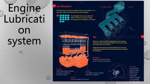
lubrication
润滑系统的主要部件有:油泵、主油道、机油冷却器、油底壳、溢流阀和机油滤 清器。
Pump In most cars, the oil pump is in the crankcase above the sump. It draws oil through a tub that extends downwards into the sump. This tube has a filter screen over its bottom end.
rub 摩擦 wear power loss功率损失 film膜
Lubrication system 润滑系统
friction 摩擦
The lubrication system must supply a continuous flow of oil to all the engine bearings and lubricated surfaces to maintain the oil film of each components and minimize wear. 润滑系统必须向所有发动机轴承和润滑表面提供连续的油流,以保持每个部 件的油膜并尽量减少磨损。 The correct oil viscosity is also essential to reduce friction 润滑油正确的粘度也是减少摩擦的必要条件 Bearing 轴承 viscosity 粘度 Component 部件 minimize [ˈmɪnɪmaɪz] 把…减至最低数量[程度]
Besides the gauze screen that prevents pieces of metal entering the pump there is an external filter which can be renewed periodically.

磷扩散均匀性的修复方法[发明专利]

磷扩散均匀性的修复方法[发明专利]

专利名称:磷扩散均匀性的修复方法专利类型:发明专利
发明人:乐雄英,李静
申请号:CN201711263983.8
申请日:20171205
公开号:CN107993930A
公开日:
20180504
专利内容由知识产权出版社提供
摘要:本发明公开一种磷扩散均匀性的修复方法,包括氧化、第一次沉积、第二次沉积、第三次沉积、推结五个步骤,且五个步骤于不相同的温度条件下完成。

通过将传统的单步磷扩散过程变为多步扩散过程,同时将传统的恒温磷扩散过程变成了变温磷扩散过程,克服了传统的磷扩散方法在界面区域容易扩散不均匀的弊端,增加多步变温磷扩散处理,可以使磷扩散沉积的界面的均匀性得到比较好的修复,提高磷扩散的均匀性的同时,提升晶硅电池的转换效率。

申请人:苏州润阳光伏科技有限公司
地址:215300 江苏省苏州市昆山开发区前进东路科技广场8楼
国籍:CN
更多信息请下载全文后查看。

往复式内燃机 声压法声功率级的测定 第4部分:现场测量简易法-最新国标
往复式内燃机 声压法声功率级的测定 第4部分:现场测量简易法-最新国标

往复式内燃机声压法声功率级的测定第4部分:现场测量简易法1 范围本文件规定了往复式内燃机声功率级的测定方法——现场测量简易法。

本文件适用于GB/T 6072.1适用范围的往复式内燃机,以及尚无合适标准可使用的其它内燃机。

注:本文件中,除特殊说明外,往复式内燃机简称为发动机。

2 规范性引用文件下列文件中的内容通过文中的规范性引用而构成本文件必不可少的条款。

其中,注日期的引用文件,仅该日期对应的版本适用于本文件;不注日期的引用文件,其最新版本(包括所有的修改单)适用于本文件。

ISO 3046-1 往复式内燃机性能第1部分:功率、燃料消耗和机油消耗的标定及试验方法通用发动机的附加要求(Reciprocating internal combustion engines —Performance —Part 1: Declarations of power, fuel and lubricating oil consumptions, and test methods —Additional requirements for engines for general use)注:G B/T 6072.1-2008往复式内燃机性能第1部分:功率、燃料消耗和机油消耗的标定及试验方法通用发动机的附加要求 (ISO 3046-1:2002,IDT)ISO 6798-1 往复式内燃机声压法声功率级的测定(Reciprocating internal combustion engines —Measurement of sound power level using sound pressure — Part 1: Engineering method) ISO 6926 声学用于声功率级测定的标准声源的性能与校准要求 (Acoustics — Requirements for the performance and calibration of reference sound sources used for the determination of sound power levels) 注:G B/T 4129-2003 声学用于声功率级测定的标准声源的性能与校准要求 (ISO 6926:1999,IDT)IEC 60942 电声学声校准器 (Electroacoustics — Sound calibrators)注:G B/T 15173-2010 电声学声校准器 (IEC 60942:2003,IDT)IEC 61260-1 电声学倍频程和分数倍频程滤波器第1部分:规范(Electroacoustics — Octave-band and fractional-octave-band filters — Part 1: Specifications)IEC 61672-1 电声学声级计第1部分:规范(Electroacoustics —Sound level meters —Part 1: Specifications)注:G B/T 3785.1-2010 电声学声级计第1部分:规范 (IEC 61672-1:2002,IDT)3 术语、定义和符号ISO 3046-1、ISO 6798-1、IEC 61260-1、IEC 61672-1界定的术语和定义适用于本文件。

德国克鲁伯的一款高温油脂

德国克鲁伯的一款高温油脂

BARRIERTA L 55 series, Art-No. 090014, 090013, 090035, 090042, en Edition 21.12.2011 [replaces edition 21.12.2011]Benefits for your application–Higher machine availability and less need for maintenance –at very high operating temperatures up to 260 °C –under the influence of aggressive media and vapours–where other lubricants might affect sensitive plastic components–Tried and tested over many years in numerous industries and component types–thanks to BARRIERTA base oils, which are made specifically to enable long-term stability –backed by a large number of approvals and references for various applications –four consistency classes to suit different applicationsDescriptionBARRIERTA is Europe's oldest high-quality brand of high-temperature lubricants based on perfluorinated polyether oil (PFPE). Today the name of BARRIERTA is widely regarded as synonymous with long-term stability and thermal resistance.Specifically made raw materials and continued development have made BARRIERTA products the first choice of lubrication experts in many sectors worldwide.BARRIERTA L 55/0-3 series long-term greases offer excellent resistance to high temperature and aggressive media and at the same time compatibility with plastics and elastomers.BARRIERTA L 55/0-3 are NSF H1 registered and therefore comply with FDA 21 CFR § 178.3570. The lubricants were developed for incidental contact with products and packaging materials in the food-processing, cosmetics, pharmaceutical or animal feed industries. The use of BARRIERTA L 55/0-3 cancontribute to increase reliability of your production processes. We nevertheless recommend conducting an additional risk analysis,e.g. HACCP.ApplicationRolling and plain bearings subject to high temperatures One of the well-known strengths of the BARRIERTA L 55 series is the products' suitability for the lubrication of bearings and guides operating under extreme temperatures. A low evaporation rate enables longest grease lives and hence longest relubrication intervals.Typical applications include:–conveyors (load and turn rollers)–kiln cart wheel bearings –calender bearings –fan bearings–chain bearings in film stretching stentersBARRIERTA L 55/2 is most frequently used for initial and long-term lubrication.For relubrication softer grades of NLGI class 1 or lower are recommended.Friction points under the influence of mediaBARRIERTA L 55 greases offer exceptionally long service lifetimes even when exposed to any of a large number of aggressive media such as concentrated acids, lyes, organic solvents or gases.In addition to their resistance to media, BARRIERTA L 55/2 and BARRIERTA L 55/3 offer also good adhesion and a sealing effect,which makes them suitable for application in –valves, fittings and installations e.g. in the chemical industry –pneumatic components–level gauges, e.g. for fuels or chemicals –seals (static, dynamic)–extraction systems Food-processing and pharmaceutical industriesAll BARRIERTA L 55 greases are registered as NSF-H1 and are therefore in compliance with FDA 21 CFR § 178.3570. The additional certification according to ISO 21469 supports the compliance with the hygienic requirements in your productionBARRIERTA L 55 seriesHigh-temperature long-term greasesProduct informationplant. You will find further information on ISO Standard 21469 on our website .White-coloured BARRIERTA L 55 special lubricants can therefore also be used on friction points where occasional contact with food products cannot be ruled out for technical reasons, e.g. in rolling and plain bearings and guides operating under high thermal loads in –automatic baking ovens –cooking or frying lines –conveyor systemsPlastic-plastic friction pointsBARRIERTA L 55 greases – irrespective of NLGI grade - are neutral towards the majority of plastic materials. Results of pertinent tests with fluoroelastomers can be found overleaf. We recommend testing lubricant compatibility with the materials in question prior to series application.Application notesFor optimum results we recommend cleaning all friction points with white spirit 180/210 and then with Kl beralfa XZ 3-1 prior to initial lubrication. Subsequently, the friction points should be dried with clean dry compressed air or hot air to remove all solvent residues.The friction point must be free from oil, grease, perspiration and contamination particles before initial lubrication.Please contact our technical sales staff for details of best practice with BARRIERTA L 55 lubricants to ensure longest lifetimes and highest performance outcomes are achieved.Minimum shelf lifeThe minimum shelf life is approx. 60 months if the product isstored in its unopened original container in a dry, frost-free place.Material safety data sheetsMaterial safety data sheets can be downloaded or requested via our website . You may also obtain them through your contact person at Kl ber Lubrication.BARRIERTA L 55 seriesHigh-temperature long-term greasesProduct informationBARRIERTA L 55 series, Art-No. 090014, 090013, 090035, 090042, en Edition 21.12.2011 [replaces edition 21.12.2011]Product data BARRIERTA L55/0BARRIERTA L55/1BARRIERTA L55/2BARRIERTA L55/3Article number090035 090042 090013 090014NSF-H1 registration129 523 129 561 129 400 129 562 Chemical composition, type of oil PFPE PFPE PFPE PFPE Chemical composition, solid lubricant PTFE PTFE PTFE PTFELower service temperature-40 °C / -40 °F-40 °C / -40 °F-40 °C / -40 °F-30 °C / -22 °F Upper service temperature260 °C / 500 °F260 °C / 500 °F260 °C / 500 °F260 °C / 500 °F Colour space white white white whiteDensity at 20 °C approx. 1.95g/cm³approx. 1.95g/cm³approx. 1.96g/cm³approx. 1.96g/cm³Shear viscosity at 25 °C, shear rate 300 s-1; equipment:rotational viscometer approx. 4 500mPasapprox. 10 000mPasapprox. 14 000mPasShear viscosity at 25°C, shear rate 300 s-1,equipment:rotational viscometer, upper limit value5 500 mPas8 000 mPasShear viscosity at 25 °C, shear rate 300 s-1,equipment: rotational viscometer, lower limit value3 500 mPas4 000 mPasKinematic viscosity of the base oil, DIN 51562 pt. 01/ASTM D-445/ASTM D 7042, 40 °C approx. 420mm²/sapprox. 420mm²/sapprox. 420mm²/sapprox. 420mm²/sKinematic viscosity, DIN 51562 pt. 01/ASTM D-445/ASTM D 7042, 100 °C approx. 40mm²/sapprox. 40mm²/sapprox. 40mm²/sapprox. 40mm²/sFlow pressure of lubricating greases, DIN 51805, testtemperature: -30 °C<= 1 400 mbarFlow pressure of lubricating greases, DIN 51805, testtemperature: -40 °C<= 1 400 mbar<= 1 600 mbarFour-ball tester, welding load, DIN 51350 pt. 04>= 6 000 >= 7 000 >= 8 000 >= 8 000Speed factor (n x dm) approx. 300 000mm/min approx. 300 000mm/minapprox. 300 000mm/minapprox. 300 000mm/minCorrosion inhibiting properties of lubricating greases, DIN 51802, (SKF-EMCOR), test duration: 1 week, distilled water <= 1 corrosiondegree<= 1 corrosiondegree<= 1 corrosiondegreeAdditional data: resistance to fluoroelastomersChange75 FKM 58580 FKM 61060 FVMQ 565 Exposure life [h] / exposure temp. [°C]168 / 160168 / 160168 / 150 Volume [%]+ 0.5+0.5- 0.3 Hardness (Shore A)+ 0.5- 1- 2Tensile strength [%]+ 15+ 15- 16 Elongation at tear [%]- 11- 11- 10Klüber Lubrication – your global specialist Innovative tribological solutions are our passion. Throughpersonal contact and consultation, we help our customers to be successful worldwide, in all industries and markets. With our ambitious technical concepts and experienced, competent staff we have been fulfilling increasingly demanding requirements by manufacturing efficient high-performance lubricants for more than 80 years.Klüber Lubrication München KG /Geisenhausenerstraße 7 / 81379 München / Germany /phone +49 89 7876-0 / fax +49 89 7876-333.The data in this document is based on our general experience and knowledge at the time of publication and is intended to give information of possible applications to a reader with technical experience. It constitutes neither an assurance of product properties nor does it release the user from the obligation of performing preliminary field tests with the product selected for a specific application. All data are guide values which depend on the lubricant's composition, the intended use and the application method. The technical values of lubricants change depending on the mechanical, dynamical, chemical and thermal loads, time and pressure. These changes may affect the function of a component. We recommend contacting us to discuss your specific application. If possible we will be pleased to provide a sample for testing on request. Kl ber products are continually improved. Therefore, Kl ber Lubrication reserves the right to change all the technical data in this document at any time without notice.Publisher and Copyright: Kl ber Lubrication M nchen KG. Reprints, total or in part, are permitted only prior consultation with Kl ber Lubrication M nchen KG and if source is indicated and voucher copy is forwarded.a company of the Freudenberg GroupProduct information。

Castrol 嘉实多主要产品汇总介绍说明

Castrol 嘉实多主要产品汇总介绍说明
Spur, bevel and planetary gearing, main gearing of wind power plants and oillubricated rolling bearings.
Spur and bevel gearings also subject to harsh conditions, longlife gear oil rolling bearings, denture clutches, drives of rail-borne vehicles
Modern worm and spur gear units, medium to high loads, rolling and sliding bearings, peak temperature up to +160 °C
Hydraulic oils HLP according to DIN 51524.2, containing heavy metals
* Final compression temperature ** Dry lubrication *** Contains solvent
HIGH PERFORMANCE LUBRICATING OILS
PRODUCT NAME
DESCRIPTION
BASE OIL
Oils for the Food and Beverage Industry
Mineral oil Mineral oil
Tribol 943 AW
Hydraulic and circulating oils
Compressor Oils
Aircol PD
Mineral compressor oil
Tribol 890

ASTM D1743-2005润滑脂防腐蚀性能测定法

ASTM D1743-2005润滑脂防腐蚀性能测定法

Designation:D1743–05a e1An American National Standard Standard Test Method forDetermining Corrosion Preventive Properties of Lubricating Greases1This standard is issued under thefixed designation D1743;the number immediately following the designation indicates the year oforiginal adoption or,in the case of revision,the year of last revision.A number in parentheses indicates the year of last reapproval.Asuperscript epsilon(e)indicates an editorial change since the last revision or reapproval.This standard has been approved for use by agencies of the Department of Defense.e1N OTE—Editorially replaced Stoddard solvent with mineral spirits in the test method to match approved change to7.5inDecember2005.1.Scope*1.1This test method covers the determination of the corro-sion preventive properties of greases using grease-lubricated tapered roller bearings stored under wet conditions.This test method is based on CRC Technique L412that shows correla-tions between laboratory results and service for grease lubri-cated aircraft wheel bearings.1.2Apparatus Dimensions—The values stated in inch-pound units are to be regarded as standard.The values given in parentheses are mathematical conversions to SI units that are provided for information only and are not considered standard.1.3All Other Values—The values stated in SI units are to be regarded as the standard.The values given in parentheses are for information only.1.4This standard does not purport to address all of the safety concerns,if any,associated with its use.It is the responsibility of the user of this standard to establish appro-priate safety and health practices and determine the applica-bility of regulatory limitations prior to use.2.Referenced Documents32.1ASTM Standards:D1193Specification for Reagent Water3.Terminology3.1Definitions of Terms Specific to This Standard:3.1.1corrosion,n—the chemical or electrochemical reac-tion between a material,usually a metal,and its environment that produces a deterioration of the material and its properties.3.1.1.1Discussion—In this test method,corrosion is mani-fested by red rust or black stains on the bearing race.Stains, through which the underlying metal surface is still visible,are not considered corrosion in Test Method D1743and shall be ignored.4.Summary of Test Method4.1New,cleaned,and lubricated bearings are run under a light thrust load for6063s to distribute the lubricant in a pattern that might be found in service.The bearings are exposed to water,then stored for4860.5h at5261°C(125 62°F)and100%relative humidity.After cleaning,the bearing cups are examined for evidence of corrosion.5.Significance and Use5.1This test method differentiates the relative corrosion-preventive capabilities of lubricating greases under the condi-tions of the test.6.Apparatus6.1Bearings—Timken bearing cone and roller assembly LM11949,and cup LM11910.4,56.2Motor,1750650-rpm speed,1⁄15hp(min).6.3Bearing Holder,consists of a160.10kg weight,upper and lower plastic collars for the bearing cone(Parts A and B),a metal screw,and a plastic collar for the cup(Part C).(See Fig.1.)6.4Plastic Test Jar,as shown in Fig.2.6.5Run-in Stand,as shown in Fig.3.1This test method is under the jurisdiction of ASTM Committee D02on Petroleum Products and Lubricants and is the direct responsibility of Subcommittee D02.G0on Lubricating Grease.Current edition approved July1,2005.Published July2005.Originally approved st previous edition approved in2005as D1743–05.2“Research Technique for Determining Rust-Preventive Properties of Lubricat-ing Greases in the Presence of Free Water,”L-41-957,undated,CoordinatingResearch Council,Inc.,219Perimeter Center Parkway,Atlanta,GA30346.3For referenced ASTM standards,visit the ASTM website,,or contact ASTM Customer Service at service@.For Annual Book of ASTM Standards volume information,refer to the standard’s Document Summary page on the ASTM website.4The sole source of supply of the apparatus known to the committee at this time is The Timken Co.,Canton,OH44706.5If you are aware of alternative suppliers,please provide this information to ASTM International Headquarters.Your comments will receive careful consider-ation at a meeting of the responsible technical committee,1which you may attend.*A Summary of Changes section appears at the end of this standard. Copyright©ASTM International,100Barr Harbor Drive,PO Box C700,West Conshohocken,PA19428-2959,United States.6.6Spindle/Thrust Loading Device ,as shown in Fig.4.(See Table 1for metric equivalents.)6.7Mechanical Grease Packer ,as shown in Fig.5and Fig.6.6.8Pliers,5,6as shown in Fig.7.6.9Syringe ,of at least 100-mL volume and with a needle of at least 16gage and a minimum length of 100mm (4in.).6.10Timer ,capable of measuring a 6063-s interval.6The sole source of supply of the Waldes Truarc Plier No.4modified as in Fig.7known to the committee at this time is TRUARC Company LLC,70East Willow Street,Millburn,NJ07041.KEY DESCRIPTIONQUANTITY1PISTON 12O RING 13WEIGHT14UPPER FLANGE 15LOWER FLANGE161⁄4−2031-1⁄4FILLISTER HD.MACH.SCREW S.S.17O RING18BEARING HOLDER 19PLASTIC JAR 110O RING1FIG.1Bearing HolderAssembly6.11Oven —A laboratory oven,essentially free of vibration,capable of maintaining 5261°C.7.Reagents7.1Purity of Reagents —Reagent grade chemicals shall be used in all tests.Unless otherwise indicated,it is intended that all reagents shall conform to the specifications of the Commit-tee on Analytical Reagents of the American Chemical Society,where such specifications are available.7Other grades may be used,provided it is first ascertained that the reagent is of sufficiently high purity to permit its use without lessening the accuracy of the determination.7.2Purity of Water —Unless otherwise indicated,references to water shall be understood to mean reagent water conforming to Specification D 1193,Type III.7.3Isopropyl Alcohol.Warning—Flammable.7.4Solvent Rinse Solution of the following composition by volume:7.4.1Isopropyl Alcohol ,90%.7.4.2Distilled Water ,9%.7.4.3Ammonium Hydroxide ,1%.Warning—Poison.Causes burns.Vapor extremely irritating.Can be fatal if swallowed.Harmful if inhaled.7.5Mineral Spirits ,reagent grade,minimum purity.(Warning—Combustible.Vapor harmful.)8.Standardization of Thrust Loading Device8.1Pack a bearing,install it into the holder and place the assembly into a plastic jar as described in 10.1through 10.4.Place the jar onto the base of the motor drive spindle and center it under the indexing pin of the drive.Lower the drive until the O ring just contacts the 1-kg weight.Run the bottom nut of the depth gage (see Fig.3)down to the stop.Place a 3-mm spacer on top of this nut.Bring the top nut down to the spacer.While holding the top nut in position,remove the spacer and run the bottom nut up and tighten it against the top nut.When the O ring is compressed against the 1-kg weight until the adjustment nut hits the stop,there will be a 29-N load added,giving a total load of 39N on the bearing.(The loads described are provided by the forces of the spring in the thrust loading spindle and sum of the 1-kg weight and spring,respectively.These loads are approximate.The 1-kg weights should be within 0.010kg of their stated values.The thrust loading spindle should be calibrated by some suitable method when it is first put into service,recalibrated periodically,and replaced if its spring does not provide sufficient force to spin the test bearings without slippage during the 60s run to distribute the grease.)Examine the O ring periodically and replace it if it shows any cracks or other signs of deterioration.8.2The thrust loading device should be standardized before use,once per day if used daily,and again if there is reason to believe that the standardization has changed.The thrust load-ing device may be standardized using one of the greases to be tested.9.Preparation of Bearings9.1Examine the test bearings carefully and select only bearings that have outer races (cups)and rollers entirely free of corrosion.During the bearing preparation handle the bearings with tongs or rubber or plastic gloves.Do not touch bearings with the fingers at any time.9.2Wash the selected bearing thoroughly in hot (52to 66°C)mineral spirits,reagent grade (Warning—Combustible.Vapor harmful.)to remove the rust preventive.Wipe the bearing cone and cup with tissue moistened in hot solvent to remove any remaining residue.Rinse the bearing a second time in fresh,hot mineral spirits,reagent grade.N OTE 1—The washing temperatures specified are considerably above the flash point of the mineral spirits,reagent grade.Accordingly,the washing operation should be carried out in a well-ventilated hood where no flames or other ignition sources are present.9.3Transfer the bearing from the mineral spirits,reagent grade to the solvent rinse solution (Warning—Poison.Causes burns.Vapor extremely irritating.Can be fatal if swallowed.Harmful if inhaled.)to remove the mineral spirits,reagent grade and any fingerprints that are present.Then rinse the bearing and slowly rotate in fresh hot (6665°C)solvent rinse solution.N OTE 2—Use fresh rinse solution to avoid the selective evaporation of the components at the rinse temperature.9.4Remove the bearing from the solvent rinse solution and place on filter paper to drain.After draining,dry the bearing in an oven at 7065°C for 15to 30min.7Reagent Chemicals,American Chemical Society Specifications ,American Chemical Society,Washington,DC.For suggestions on the testing of reagents not listed by the American Chemical Society,see Analar Standards for Laboratory Chemicals,BDH Ltd.,Poole,Dorset,U.K.,and the United States Pharmacopeia and National Formulary,U.S.Pharmacopeial Convention,Inc.(USPC),Rockville,MD.Test Jar SpecificationsInner Diameter Range:3.11–3.31in.(79–84mm)Inner Height Range:3.5–4.0in.(89–102mm)FIG.2Plastic TestJarFIG.3Run-in StandDrawingFIG.4Spindle/Thrust Loading Device TABLE1Metric Equivalents for Figs.3and4 Inches Millimetres 1⁄320.79 1⁄8 3.18 5⁄32 3.97 3⁄16 4.76 5⁄327.14 5⁄167.94 3⁄89.53 7⁄1611.11 1⁄212.70 19⁄3215.08 21⁄3216.67 3⁄419.05 125.40 11⁄828.58 13⁄1631.26 11⁄431.75 111⁄3234.131.49537.971.50038.1019⁄1639.69 11⁄444.451.78545.34115⁄1649.211.94649.4327⁄3256.36 21⁄457.15 211⁄3259.53 376.209.5Permit the bearing to cool to room temperature and reexamine surfaces to assure that corrosion-free and free-turning specimens have been selected.(Care should be taken not to spin the bearings after cleaning and drying.)9.6Wash and dry the bearing packer using the same technique as for the preparation of the bearings.10.Procedure10.1With the reservoir of grease packer resting on a clean bench top,and while wearing gloves,place bearing cup with small diameter face down into the recess of the packer.Place the bearing cone over the cup,and while holding the bearing assembly against the packer,lift and invert the whole unit and return it to the bench.10.2Fill the reservoir with the grease sample,and use the plunger to force grease through the bearing.Carefully remove the plunger from the reservoir to avoid sucking air into the bearing,and slide the packer unit over the edge of the bench.While holding the bearing assembly in the packer,invert the unit to its original position on the bench.10.3Using a small square-ended spatula,remove excess grease from the bearing bore and the annulus between the grease packer and outer perimeter of the bearing cup.The bearing is removed from the packer by either use of the pliers or by placing gloved index finger in the bore and lifting out.While holding the bearing,use the spatula to remove excess grease above the cage on both sides of the bearing.This procedure is done to ensure that approximately the same volume of grease is used each time.10.4Using Fig.1as a guide,hold the packed bearing between gloved fingers with large inside diameter of cup downward and insert the small diameter plastic flange on top of the bore,and the larger flange into the bottom of the bore.Slide the bearing assembly onto the 1-kg weight so that the largediameter flange fits into the recess on the top of the weight.Insert the bolt through the assembly and screw the bolt tightly into the weight.Lower the plastic bearing holder (Part 8)over the bearing (the large O ring faces upward).Press down the holder so that the bearing fits squarely into the holder.10.5Invert a plastic jar over the bearing assembly.Slide the two components over the edge of the bench,and with fingers pressing the weight against the inner bottom of the jar,invert the entire assembly.10.6Place the jar onto the base of the motor driven spindle and center under the indexing pin of the drive.Start the motor and bring the drive into the center of the 1-kg weight and load until the nut hits the depth stop.Run for 60s,raise the drive,and allow the bearing to coast to a stop.Extreme care should be taken not to break the contact between the races and rollers at this point and in the following steps.10.6.1At no time during or after the 60s run shall the grease be redistributed or forced back into the bearing.10.7Freshly boil the distilled water for 1065min to remove carbon dioxide and cool to 2565°C.10.8Fill a clean syringe with 10065mL of distilled water from 10.7.With the run-in bearing in the jar,simultaneously start a timer and begin adding the water into the hole provided for this purpose in the bearing holder.Add the 100mL of water within 2063s.When the timer shows 5063s start withdrawing the water.When the timer shows 6063s,complete the withdrawal of 7065mL of water.Leave the remaining 3065mL of water in the jar.Make sure that water does not touch the bearing after 7065mL is withdrawn.It may be difficult to withdraw 7065mL water in 10s using a 16gage needle.A larger needle may be required.10.9Screw the cap on the jar and transfer to a dark oven essentially free from vibration for 48h at 5261°C.N OTE —Tolerances are 0.003in.unless specified otherwise.FIG.5Bearing PackerBrass10.10Prepare three bearings with each grease to be tested.Each group of three bearings is one test.11.Rating Procedure11.1Remove the bearing from the test jar and place the bearing cup in a 50+50mixture by volume of isopropyl alcohol (Warning—Flammable)and mineral spirits,reagent grade (Warning—Combustible.Vapor harmful).The solvent mixture can be heated to facilitate the removal of the grease.Agitate vigorously to remove the grease.Repeat the rinsing using fresh solvent mixture or gently wipe the bearing with a clean cloth or tissue to ensure that traces of grease are removed.11.2Transfer the bearing cup from the solvent and allow to dry on clean filter paper.11.3Examine the cup raceway for evidence of corrosion without the use of magnification (Section 5).Use only a pass or fail rating.Criteria for failure shall be the presence of any corrosion spot 1.0mm or larger in the longest dimension.Ignore the number ofspots.KEY DESCRIPTIONQUANTITY1GREASE PACK PLUNGER 12CYLINDER13LM11900BEARING ASSEMBLY 14STUD 15BASE1FIG.6BearingPacker—Alternative11.3.1Spots that are easily removed by rubbing lightly with soft tissue (alone or wetted with any solvent nonreactive to rust or steel at room temperature)shall not be considered as corrosion in the rating.12.Report12.1The reported result shall be the pass or fail rating as determined by at least two of the three bearings.13.Precision and Bias13.1Due to the nature of the results,the precision of this test method was not obtained in accordance with RR:D02–1007,“Manual on Determining Precision Data for ASTM Methods on Petroleum Products and Lubricants.”13.2Precision —The precision of this test method as deter-mined by statistical examination of interlaboratory results is as follows:13.2.1Repeatability may be judged by the fact that 94%of duplicate results obtained by nine laboratories with six samples were in agreement.13.2.2Reproducibility may be judged by the fact that nine laboratories matched consensus 96%of the time with six samples showing good or poor protection against corrosion.13.3Bias —No statement is made about the bias of this test method since the result merely states whether there is conform-ance to the criteria for success specified in the procedure.14.Keywords14.1bearing;corrosion;lubricating grease;rustAPPENDIXES(Nonmandatory Information)X1.RATIONALEX1.1The current version of Test Method D 1743differs primarily from the older version Test Method D 1743–73(1981)e 2in two major areas.X1.1.1First,the current procedure uses a new run-in stand and bearing holder.This equipment change was designed to reduce the possibility of the bearing rollers and race breaking contact after run-in.When these surfaces break contact,direct water contamination and unrepeatable rusting can occur.X1.1.2Second,the rating procedure was simplified to a pass/fail statement.Instead of relating failure to the number of corrosion spots,the current procedure now defines a failure in terms of one corrosion spot greater than 1.0mm in length.X1.2One disadvantage of the current procedure is thatfewer tests can be run per unit time without purchasing additional bearing holders.X1.2.1The committee felt that the procedure for Test Method D 1743–73should remain available for those labora-tories needing a quicker screening test method.During the round-robin development of the current test method,a limited comparison of the two test methods was made.Although not enough data was collected for a meaningful statistical analysis,the two procedures gave good agreement.X1.3The procedure of D 1743–73modified with the new rating method is incorporated as Appendix X2.It should be noted however,that the current procedure shall be used for refereepurposes.FIG.7Plier to Remove Bearing from GreasePackerX2.ALTERNATE CORROSION TEST PROCEDUREX2.1ScopeX2.1.1This test method covers the determination of the corrosion preventive properties of greases using grease-lubricated tapered roller bearings stored under wet conditions.This test method is based on CRC Technique L 41that shows correlation between laboratory results and service for grease lubricated aircraft wheel bearings.X2.1.2The values stated in inch-pound units are to be regarded as the standard.X2.2Referenced Documents X2.2.1See Section 2.X2.3Terminology X2.3.1See Section 3.X2.4Summary of Test MethodX2.4.1Clean new bearings are lubricated,then run under a light thrust load for 6063s so as to distribute the lubricant in a pattern that might be found in service.The bearings are subsequently stored for 4860.5h at 5261°C (12562°F)and 100%relative humidity.After cleaning,the bearing cups are examined for evidence of corrosion.X2.5Significance and Use X2.5.1See Section 5.X2.6ApparatusX2.6.1Bearings ,4,5Timken bearing cone and roller assem-bly and cup.X2.6.2Container ,237-cm 3(8-oz)clear glass jar (85.7mm (33⁄8in.)high,69.8mm (23⁄4in.)in diameter)fitted with a wax-lined screw cap.X2.6.3Bearing Support ,14⁄35to 18⁄38taper glass adapter.5,8X2.6.4Motor ,1750650-r/min speed.X2.6.5Spindle ,No.4rubber stopper drilled and fitted to motor shaft.X2.6.6Thrust Loading Device ,as shown in Fig.X2.1.(See Table X2.1for metric equivalents.)X2.6.7Mechanical Grease Packer ,similar or equivalent to the mechanical bearing packer as shown in Fig.X2.2.(See Table X2.1for metric equivalents.)X2.7ReagentsX2.7.1See Section 7.8The sole source of supply of the apparatus known to the committee at this time is Thomas Scientific Co.,P.O.Box 99,Swedesboro,NJ08085.FIG.X2.1Thrust LoadingDevicesX2.8Standardization of Thrust Loading DeviceX2.8.1Place the handle of the thrust loading device (Fig.X2.1)in a vise with the thrust loading device in an upright position.Place a 2.760.3-kg (660.7-lb)weight on the cup and mark the barrel to identify the proper handle position.X2.9Preparation of BearingsX2.9.1Examine the test bearings carefully and select only bearings which are entirely free of corrosion.During the bearing preparation handle the bearing with tongs.Bearings should not be touched with the fingers at any time.X2.9.2Wash the selected bearing thoroughly in hot (52to 66°C (125to 150°F))Stoddard solvent (Warning—Combustible.Vapor harmful.)to remove the rust preventive.To ensure complete removal of the rust preventive,subject the bearing to a second wash in fresh hot 52to 66°C Stoddard solvent.X2.9.3Transfer the bearing from the Stoddard solvent to the solvent rinse solution to remove the Stoddard solvent and any fingerprints that are present.Then rinse the bearing and slowly rotate in fresh hot (minimum 66°C)solvent rinse solution (Warning—Poison.Causes burns.Vapor extremely irritating.Can be fatal if swallowed.Harmful if inhaled.).X2.9.4Remove the bearing from the solvent rinse solution and place on filter paper to drain.After draining,dry the bearing in an oven at 7065°C (160°F)for 15to 30min.X2.9.5Permit the bearing to cool to room temperature and reexamine surfaces to assure that corrosion-free and free-turning specimens have been selected.(Care should be taken not to spin the bearings after cleaning and drying.)X2.9.6Wash and dry the thrust loading device and bearing packer using the same technique as for the preparation of the bearings.X2.10ProcedureX2.10.1Three new bearings are required for each test.Weigh the bearing (cone and cup assembly)to the nearest 0.1g using clean oil-resistant gloves while handling the bearing.X2.10.2Pack the assembled bearing with the grease sample using a mechanical packer similar or equivalent to the oneshown in Fig.X2.2.Keep the cone and cup assembled for the remaining operations through step X2.10.10.X2.10.3Wipe off the excess grease and place the assembled bearing in the thrust loading device (Fig.X2.1).Lock the bearing in place with the locking screw.X2.10.4Place the bearing cone against the rubber stopper on the motor shaft and apply a thrust load by pushing the handle of the thrust loading device up to the calibration mark on the barrel.X2.10.5Rotate the bearings at 1750650r/min for 1061s,turn off the motor and allow to coast to stop.Remove the bearing from the spindle and loosen the locking screw and push the bearing out of the cup with the rod.X2.10.6By removal of the excess grease and uniform redistribution of the sample,adjust the total quantity of grease on the assembled cone and cup to within 2.160.1cm 3(2.060.1g).Then wipe over the exterior surfaces of the assembled bearing a thin film of grease (about 0.1g).For greases having densities significantly higher than mineral oil based greases,adjust the quantity of the grease to equal 2.160.1cm 3.X2.10.7Place the bearing in the thrust loading device and lock the bearing with the locking screw.Place the bearing cone against the rubber stopper on the motor shaft and apply a thrust load of 26.7N (6lbf)by pushing the handle up to the calibration mark on the barrel.X2.10.8Rotate the bearing at 1750650rpm for 6063s,turn off the motor and allow to coast to stop (see Note X2.1).Remove the bearing from the spindle and loosen the locking screw and push the bearing out of the cup with the rod.Extreme care should be taken not to break the contact between the races and rollers at this point and in the following steps.X2.10.9Place the bearing on the bearing support in such a manner that the weight of the outer race will maintain contact between the races and rolling elements.By means of the bearing support immerse the entire assembly for 1062s into freshly boiled distilled water which has been cooled to 2565°C (use a new supply of water for each bearing).X2.10.10Allowing any water on the bearing to remain,place the assembly in the glass jar to which has been added 561mL of distilled water,tighten the screw cap firmly (Note X2.1)and store in a dark oven,located in an area essentially free from vibration for 4860.5h at 5261°C (12562°F).N OTE X2.1—It is recommended that a tube or rod be attached to the center of the screw cap to drop over or inside the glass adapter or that other suitable means be used to prevent the assembly from sliding to the side of the jar during handling.Any such attachments should not cause rotation of the bearing adapter when tightening the screw cap on the jar.X2.11Rating ProcedureX2.11.1Remove the bearing from the test jar and place the bearing cup in a 50+50mixture by volume of isopropyl alcohol and Stoddard solvent.The solvent mixture can be heated to facilitate the removal of the grease,observing the proper precautions for a flammable mixture.Agitate vigorously to remove the grease.Repeat the rinsing using fresh solvent mixture to ensure that traces of grease are removed.X2.11.2Transfer the bearing cup from the solvent and allow to dry on clean filter paper.TABLE X2.1Metric Equivalents for Figs.X2.1and X2.2in.mm in.mm 0.0010.02511⁄828.60.0030.076113⁄1630.21⁄320.7911⁄431.81⁄16 1.59 1.37334.871⁄8 3.18 1.37534.923⁄16 4.7617⁄1636.57⁄32 5.5615⁄841.31⁄4 6.35 1.936849.195⁄167.94 1.938049.2210⁄327.94161⁄6449.65⁄1210.58250.87⁄1611.1221⁄457.21⁄212.7023⁄860.30.5914.99376.23⁄419.05613⁄161730.812520.6481⁄1620515⁄1623.81X2.11.3Examine the cup raceway for evidence of corrosion without the use of magnification (Section 3).Only a pass or fail rating shall be used.Criteria for failure shall be the presence of any corrosion spot 1.0mm or larger in the longest dimension.The number of spots is ignored (see Note X2.1).X2.12ReportX2.12.1See Section 12.X2.13Precision and BiasX2.13.1No precision in accordance with RR:D02–1007,“Manual on Determining Precision Data for ASTM Methods on Petroleum Products and Lubricants,”was established.X2.13.2Precision —Limited testing conducted in concert with testing done to establish the repeatability and reproduc-ibility precision for the revised procedure indicated that this procedure may have similar precision.X2.13.3Bias —No statement is made about the bias of this test method since the result merely states whether there is conformance to the criteria for success in the procedure.SUMMARY OF CHANGESSubcommittee D02.G0has identified the location of selected changes to this standard since the last issue,(D 1743–05),that may impact the use of this standard.(Approved July 1,2005.)(1)Added Fig.2.(2)Deleted Falex equipment footnote.Subcommittee D02.G0has identified the location of selected changes to this standard since the last issue,(D 1743–01),that may impact the use of this standard.(Approved June 1,2005.)(1)Deleted Specification D 235from the Referenced Docu-ments and 7.5.(2)Revised 7.5.FIG.X2.2Mechanical BearingPackerCopyright ASTM International, 100 Barr Harbor Drive, West Conshohocken, Pennsylvania 19428, USA Distributed under ASTM license agreement by Shanghai Institute of Standardization (SIS)Addr: 1219, 1227 Changle Rd., Shanghai, 200031. Tel: 86-21-64370807D1743–05a e1ASTM International takes no position respecting the validity of any patent rights asserted in connection with any item mentionedin this ers of this standard are expressly advised that determination of the validity of any such patent rights,and the riskof infringement of such rights,are entirely their own responsibility.This standard is subject to revision at any time by the responsible technical committee and must be reviewed everyfive years andif not revised,either reapproved or withdrawn.Your comments are invited either for revision of this standard or for additional standardsand should be addressed to ASTM International Headquarters.Your comments will receive careful consideration at a meeting of theresponsible technical committee,which you may attend.If you feel that your comments have not received a fair hearing you shouldmake your views known to the ASTM Committee on Standards,at the address shown below.This standard is copyrighted by ASTM International,100Barr Harbor Drive,PO Box C700,West Conshohocken,PA19428-2959,United States.Individual reprints(single or multiple copies)of this standard may be obtained by contacting ASTM at the aboveaddress or at610-832-9585(phone),610-832-9555(fax),or service@(e-mail);or through the ASTM website().11ASTM International 版权所有, 100 Barr Harbor Drive, West Conshohocken, Pennsylvania 19428, USA由上海市标准化研究院(SIS)根据ASTM授权协议进行销售 地址: 上海市长乐路1219/1227号 邮编: 200031联系。

激光辅助磁存储模式探讨

激光辅助磁存储模式探讨

New Developments in Laser-Assisted MagneticRecordingHiroyuki Katayama,Masaki Hamamoto,Jun-ichi Sato,Yoshiteru Murakami,and Kunio KojimaAbstract—Recent progress in laser-assisted magnetic recording, which combines optical and magnetic recording technologies,is de-scribed in this paper.This study confirms that laser-assisted mag-netic recording is a good candidate for high areal density mag-netic recording.Improved disk performance was demonstrated in the area of frequency response,media noise,and thermal decay. The improvements in media design include the change in temper-ature dependence of the recording layer,an increased perpendic-ular anisotropy,and a thermally efficient layer structure.These im-proved media properties results in a high linear density and good thermal stability.Index Terms—Disk noise,laser-assisted,perpendicular magnetic recording,thermally-assisted,thermal stability.I.I NTRODUCTIONN OW THAT laboratory demonstrations have reached the areal density of20Gb/in2,the issue of thermal stability has become a major concern for the magnetic disk drive storage industry.Various solutions have been proposed to overcome the thermal stability problem in higher density recording. New technologies which combine both magnetic and optical recording methods have recently become likely candidates to break through the current superparamagnetic limits[1]–[5]. Near field optics using a solid immersion lens[1]or micro-lens optics with high numerical aperture[2]placed on a magnetic flying head slider have been developed for magneto-optical (MO)recording to achieve smaller diffraction limited spots with lasers that are available today.Another combined tech-nology in which perpendicular thermo-magnetic recording is coupled with magnetic flux detection has recently been introduced[3],[4].It utilizes the higher resolution and sensi-tivity of giant magneto-resistive(GMR)detection compared with optical detection.It should be pointed out that all of the above methods employ MO recording materials that consist of rare-earth(RE)transition-metal(TM)alloys.These materials are amorphous and have perpendicular anisotropy.The domain stability in these materials is expected to be better than those of the superparamagneticaly limited particles used in longitudinal magnetic recording media.We have proposed a new method of perpendicular magnetic recording employing laser-assisted read/write functions and ex-perimentally confirmed that it works[5].In the new method,Manuscript received July9,1999.H.Katayama,M.Hamamoto,J.Sato,and K.Kojima are with the Advanced Technology Research Laboratories,Sharp Corporation,Nara,632-8567Japan (e-mail:katayama@cmn.mkhar.sharp.co.jp).Y.Murakami is with the Optical Disk Systems Development Center,Sharp Corporation,Nara,632-8567Japan.Publisher Item Identifier S0018-9464(00)00441-6.narrow tracks are written and read by magnetic recording of a ferri-magnetic material with a magnetic compensation tem-perature while locally heating the media with a laser beam. Thereby we are aiming at both higher linear density of perpen-dicular magnetic recording and higher track density of optical recording.In our previous work,the preliminary results were not good enough for practical application.The media charac-teristics had to be improved.In this report,we have studied the optimization of the laser-assisted magnetic recording from the point of view of a media design,that is,the magnetic proper-ties,the thermal responses,and the read/write performance of the media.Such issues as media noises and thermal stability are also addressed from the point of practical use.II.E XPERIMENTSThe laser-assisted magnetic recording media consisted of a dielectric layer of a60nm AlN film,a TbFeCo magnetic recording film with perpendicular anisotropy and a20nm pro-tective amorphous carbon(a-C)film.They were single-layer perpendicular recording media.They were sputtered onto glass disk substrates of2.5in in diameter and/or microsheet glass by magnetron sputtering at room temperature.The magnetic layer was prepared by co-sputtering of Tb,Fe,and Co tar-gets.The alloy composition was controlled by changing the applied power to each target.In this study,the Ar sputtering gas pressure was lowered to less than0.2Pa.The lower Ar pressure enhanced the perpendicular anisotropy,which in turn improved the laser-assisted recording performance as described in the next section.The AlN film was deposited by rf-reactive sputtering in a composite gas of Ar and N2.On top of the a-C overcoat,liquid perfluoropolyether(PFPE)films were applied for lubrication.Magnetic properties were measured by using a vibrating sample magnetometer(VSM).An X-ray fluorescence(XRF) analyzer was used for measuring the composition of the magnetic layer.Dynamic read/write evaluation was carried out using a test stand having an air-bearing spindle and a piezo-stage for precision alignment of a magnetic head relative to the optical spot.The test setup was comprised of a magneto-resistive (MR)head merged with thin film write head designed for longitudinal recording that was positioned on one side of the test disk,and an optical pickup for laser assisting that was positioned on the other side of the test disk.An assist laser beam irradiated the recording medium through the glass disk substrate.Table I shows the specifications of the magnetic head and the optical pickup employed in the experimental setup.0018–9464/00$10.00©2000IEEETABLE IS PECIFICATIONS FOR THE M AGNETIC W RITE /R EAD H EAD AND THE O PTICAL PICKUPFig.1.Magnetic properties of Tb 19Fe 69Co 12film (100nm)as a function of temperature.Recording measurements were performed at a linear velocity of 10to 11m/s with a disk rotational speed of 3600rpm.The flying height was about 50nm.III.R ESULTS AND D ISCUSSIONA.Improvement of Media DesignIn the present work,an underlayer of AlN film was inserted between the substrate and the magnetic recording layer.The underlayer works as an optical interference layer and thereby makes the magnetic film more effectively heated with the inci-dent laser beam.Also,in this study,the Curie temperature of the TbFeCo film was reduced by increasing the Fe/Co ratio.The lower Curie temperature results in a greater power sensitivity during laser-assisted reading and writing.Besides,the perpen-dicular anisotropy of the TbFeCo film could be increased with the lower sputtering gas pressure which results in more ther-mally stable domains.Fig.1shows the temperature dependence of the remanent magnetization and the coercive force of the magnetic recording film (Tb 19Fe 69Co 12)with a thickness of 100nm.The Curie temperature was found to be reduced to about 250lowerthanouroldmediawithlarge Co content in the earlier report [5].Typical hysteresis loops at 175KATAYAMA et al.:NEW DEVELOPMENTS IN LASER-ASSISTED MAGNETIC RECORDING197Fig.4.Dependence of the signal levels of the disk with a Tb 19Fe 69Co 12film (100nm)on the read assist laserpower.Fig.5.Dependence of the signal levels of the disk with a Tb 19Fe 69Co 12film (50nm)on the read assist laser power.fixed at 7.5mA,and assist laser power for recording was set at 6mW in the rest of this study.Laser-assisted reproduced signals as a function of a read assist laser power are shown in Figs.4and 5for disks with Tb 19Fe 69Co 12films with thicknesses of 100nm (disk A)and 50nm (disk B),respectively.The increase of carrier levels with a read assist laser power in both disks is ascribed to the increase of the magnetization for temperatures just above a compensation temperature.This increase in magnetization with temperature is the basis for the laser-assisted reading process.Also the width of the recorded domains was found to be about 0.5µm as measured with a magneto-optical microscope image.The recorded domains were much narrower than the width of the write head because of the laser-assisted writing.The output signals from disks A and B degraded irreversibly above an assist laser reading power of 5and 4.5mW,respectively.The maximum of the carrier to noise ratio (C/N)was around 3mW for disk A and 2.5mW for disk B.These differences in assist laser power resulted from the different thermal efficienciesofFig.6.Frequency response of the reproduced signal for disks A and B.the two disks owing to media thickness differences.The thinner media,however,resulted in a smaller signal because of lower leakage flux from the magnetic layer.The optimum laser power for read assist was found to be 3mW for the 100nm TbFeCo medium.This power was much smaller than the read assist power of 6mW which was obtained in our previous report [5].This lower power requirement is due to the AlN underlayer and the lower Curie temperature.B.Frequency ResponseNext we demonstrated the improved frequency response in laser-assisted magnetic recording.The dependence of carrier and noise levels on the recording frequency was measured for both disks A and B shown in Fig.6.The read assist laser power was 3mW for disk A and 2.5mW for disk B.At higher fre-quencies over 50MHz,the carrier level of disk B with a thinner magnetic layer tended to show a faster loss of amplitude com-pared to that of disk A.However,other than these slight high fre-quency differences,the frequency dependence of the two media was independent of the film thicknesses.In Fig.7,we compared the frequency response of the im-proved medium (disk A)having a Fe-rich TbFeCo film in this study with that of the old medium employing a Co-rich TbFeCo film in the previous report [5].The read assist laser power for the old medium was 6mW.Also,the frequency response of the nonassisted medium with a magnetic layer of Tb 28Fe 21Co 51was measured by recording only with the magnetic head for compar-ison.The carrier levels of these three media differed owing to their different residual magnetization.Hence their C/N’s were compared with each other.The disk A medium exhibited signal quality and frequency response much better than those of the Co-rich old medium.A C/N of 36to 38dB was obtained even at 40MHz (185kFCI)for disk A.Disk A has the possibility of two times higher frequency recording compared with the old medium.This frequency response can be explained by the lower Curie198IEEE TRANSACTIONS ON MAGNETICS,VOL.36,NO.1,JANUARY2000Fig.7.Frequency response of the improved medium(disk A)compared with the nonthermally-assist and the old thermally-assisted media designs. temperature and larger perpendicular anisotropy of the disk A medium.The old medium leaves some magnetization even at a high recording temperature because of its higher Curie temperature.Therefore,the self-demagnetization as well as the lower perpendicular anisotropy are considered to degrade the recording performance,especially in high frequencies. Furthermore,disk A is capable of the same high frequency recording performance as the nonassisted medium as shown in Fig.7.Thus the laser-assisted magnetic recording was found to be suitable for high frequency recording,considering its capability of recording high coercivity media by thermally assisted writing.C.Noise AnalysisIn conventional perpendicular magnetic recording,the medium noise has been a serious problem.The main origin of the noise for CoCr-alloy perpendicular media is supposed to be from reverse domains between the recorded transitions. It has also been reported that the squareness of the M-H loop effects the noise reduction[6].Laser-assisted magnetic recording is a type of perpendicular magnetic recording.Hence its noise characteristic is a crucial issue.Because of the large perpendicular anisotropy and the amorphous structure of the recording TbFeCo film,lower disk noise could be expected. Instead,thermal interference between an MR head and a disk medium might become a concern.Fig.8shows the DC-erased disk noise spectra for dif-ferent laser powers when doing thermally-assisted reading. DC-erasing of the tracks was performed by applying a constant magnetic field under the irradiation of6mW of write assist laser power.The DC-erase noise at a read assist laser power of less than1.5 mW was quite low over the whole frequency range.This demon-strates that this medium was a potentially low noise medium. On the other hand,disk noise,especially in the lower frequency band,increased abruptly at a read assist laser power of morethan Fig.8.DC-erase noise spectra for laser-assistedreading.Fig.9.Noise spectrum for15MHz recording.3mW.This noise increase was obtained on a disk with only the protective a-C film and no magnetic layer.Therefore this noise was not caused by magnetic origins.We believe that the noise was a consequence of thermal interference(TI)between an MR head and the disk surface[7].Laser-assisted heating of the disk surface is the most likely cause of the TI.It is noteworthy that the disk noise at lower frequencies was reduced at a lower assisting laser power.Thus the thermal design of the medium becomes important from this point of view.Disk noise spectrum for15MHz(69kfci)recording is also shown in Fig.9.There was little increase in disk noise except for that at lower frequencies which was equivalent to the DC-erase noise shown in Fig.8.The write noise increased only around the recording frequency and the increase was found to be no more than3dB.This seems to be due to a reduced level of transition noise in this medium.D.Thermal FluctuationFinally we evaluated the thermal decay in the laser-assisted magnetic recording media.From the point of view of thermally-activated decay of the recorded data,laser-assisted magnetic recording seems to be not preferable because of laser irradia-tion heating during the read process.Hence the thermal decay should be one of the first things to evaluate when considering laser-assisted magnetic recording.KATAYAMA et al.:NEW DEVELOPMENTS IN LASER-ASSISTED MAGNETIC RECORDING199Fig.10.Time dependence of the remanent magnetization of an improvedmedium.Fig.11.Time dependence of the laser-assisted recording signal for an improved medium.Fig.10shows the time dependence of the remanent magne-tization (Mr)at various temperatures for an improved medium.And Fig.11shows the same relationship for a laser-assisted re-produced signal with a read assist power of 3mW.There was no change in both Mr and readout signal.Even the squareness of the M-H loops showed no deterioration.It should be noted that a longer bit (4.5kfci),which is under a stronger demagnetiza-tion field in the perpendicular magnetic recording,exhibited no degradation in its signal amplitude.Neither did the shorter bit (112kfci).This excellent thermal stability was a consequence of the increased perpendicular anisotropy of improved media and its higher coercivity.IV .S UMMARYWe have reported the recent progress in the optimum design of laser-assisted magnetic recording media.The optimization included an Fe-rich TbFeCo recording layer with a low Curie temperature,an enhanced perpendicular anisotropy by sput-tering under a low Ar pressure,and an AlN underlayer for optical interference.These optimization studies have confirmed the good potential for laser-assisted magnetic recording for achieving higher areal density recording,that is,achieving higher linear density,better thermal stability,and lower media noise.The main results obtained are listed below:1)Frequency response was improved;The C/N of 36to 38dB was obtained at 40MHz (185kfci).This makes it possible to achieve twice the linear density compared with our previous results [5].There was also no signal deterioration due to the laser-assisted recording method itself.2)Laser-assisted reading caused thermal interference (TI)between the heated media and the MR head.This TI caused an increase in the disk noise at lower frequencies.However,disk media which is designed to require a lower laser-assisted read power could reduce this type of noise.The improved TbFeCo film was found to be a potentially low noise medium.3)The enhanced perpendicular anisotropy of the improved TbFeCo film and its high coercivity promises very good thermal stability.A CKNOWLEDGMENTThe authors would like to thank Dr.Ohta for his interest and encouragement of this work.They are also thankful to the people who work at Optical Disk Systems Development Center and Precision Technology Development Center for their assis-tance.R EFERENCES[1]G.Knight,“Beyond the superparamagnetic limit l:Near-fieldrecording,”Data Storage ,pp.23–30,Feb.1998.[2]J.Davis,“Beyond the superparamagnetic limit ll:Far-field recording,”Data Storage ,pp.33–36,Feb.1998.[3]H.Saga,H.Nemoto,H.Sukeda,and M.Takahashi,“New recordingmethod combining thermo-magnetic writing and flux detection,”Jpn.J.Appl.Phys.,vol.38,pp.1839–1840,1999.[4]H.Nemoto,H.Saga,H.Sukeda,and M.Takahashi,“Exchange-coupledmagnetic bilayer media for thermomagnetic writing and flux detection,”Jpn.J.Appl.Phys.,vol.38,pp.1841–1842,1999.[5]H.Katayama,S.Sawamura,Y .Ogimoto,J.Nakajima,K.Kojima,and K.Ohta,“New magnetic recording method using laser assisted read/write technologies,”J.Magn.Soc.Jpn.,vol.23,pp.233–234,1999.[6]N.Honda,J.Ariake,K.Ouchi,and S.Iwasaki,“Low noise Co-Cr-Nbperpendicular recording media with high squareness,”IEEE Trans.Magn.,vol.34,pp.1651–1653,1998.[7]K.B.Klaassen and J.C.L.van Peppen,“Electronic abatement ofthermal interference in (G)MR head output signals,”IEEE Trans.Magn.,vol.33,pp.2611–2616,1997.[8]H.Katayama,S.Sawamura,Y .Ogimoto,J.Nakajima,K.Kojima,and K.Ohta,“New magnetic recording method using laser assisted read/write technologies,”in Technical Digest of MORIS’99,1999,p.164.。

影响航空润滑油粘度的因素探究

影响航空润滑油粘度的因素探究

影响航空润滑油粘度的因素探究郝敬团;姚婷;马玉红;杨宏伟【摘要】综述了近年来温度、压力和剪切力对航空润滑油粘度影响的研究进展,给出了温度-粘度、温度-压力-粘度的关系经验公式,并比较了润滑油关于剪切力的实验方法.不同分子量的润滑油的粘度统计分析表明,这些公式较好地拟合了润滑油的粘度变化;压力对润滑油粘度影响的经验公式计算表明,对于在高压条件下工作的润滑油,润滑油粘度受压力影响很大.【期刊名称】《广州化工》【年(卷),期】2014(042)008【总页数】4页(P29-31,49)【关键词】航空润滑油;温度-粘度;压力-粘度;剪切力-粘度【作者】郝敬团;姚婷;马玉红;杨宏伟【作者单位】空军勤务学院航空油料物资系,江苏徐州 221000;空军勤务学院航空油料物资系,江苏徐州 221000;空军勤务学院航空油料物资系,江苏徐州 221000;空军勤务学院航空油料物资系,江苏徐州 221000【正文语种】中文【中图分类】TE626.34粘度是影响润滑油产品质量的一个重要因素,它不仅是划分润滑油牌号的主要依据,还能表征润滑油在润滑系统中的流动、低温启动、冷却以及密封件泄漏等使用特征。

如果润滑油的粘度过小,就难以形成足够厚度的油膜,使摩擦面间不能形成正常而连续的润滑层,造成机械的磨损,严重时会导致曲轴轴瓦烧蚀;另外,粘度太小,还会使发动机气缸的密封性变差,造成气缸漏气、功率下降、稀释和污染润滑油等后果[1]。

相反,当润滑油粘度过大时,其流动性变差,运转阻力增大,输油消耗的功率增加,润滑油不能及时地流到相应润滑部位,摩擦面出现干摩擦。

因此,正确选择润滑油的粘度是保证机械正常工作的前提。

特别是现代军用飞机,其轴承转速快、负荷大,对润滑油的应用提出更高的要求。

飞机飞行时,涡轮的瞬间温度可高达1 400℃,发动机润滑油长期处于150~200℃的环境中;空气流经压缩机、燃烧室时,压力剧增,润滑油的粘度也会随压力成倍增加,当压力很高时,润滑油会变成固体;涡轮转子的转速约为10 200~13 300r/min,剪应力达4 000~6 000 MPa,高速转动的转子对润滑油分子产生极大的剪切作用。

全氟聚醚润滑油在高温下的腐蚀性研究

全氟聚醚润滑油在高温下的腐蚀性研究

2019年4月Apr.2019润滑油LUBRICATING OIL第34卷第2期Vo l.34,No.2DOI:10.19532/j.cnki.cn21-1265/tq.2019.02.006文章编号:1002-3119(2019)02-0023-04全氟聚醚润滑油在高温下的腐蚀性研究王俊英1,2,张香文1,2(1.天津大学化工学院先进燃料与化学推进剂重点实验室,天津300072;2.天津化学化工协同创新中心,天津300072)摘要:全氟聚醚(简称PFPE)是未来航空涡轮发动机润滑的最佳候选耐高温功能液。

但在高温下,有金属铁及其合金存在时,全氟聚醚会发生降解并腐蚀金属铁及其合金。

对具有不同平均分子量的K型全氟聚醚基础油在300ħ下的腐蚀性进行了测试,显示全氟聚醚对金属的腐蚀性与其平均分子量无关。

合成出全氟聚醚修饰的胺、硫醚、苯醚和噻唑4种腐蚀抑制剂,重点评价了它们的抗腐效果。

添加剂的加入量对其抗腐蚀性能也有一定影响。

结果表明噻唑类添加剂能够完全抑制全氟聚醚基础油腐蚀不锈钢试片。

关键词:全氟聚醚;高温;腐蚀性;添加剂中图分类号:TE626.34文献标识码:AStudy on Corrosion of Perfluoropolyalkylether Lubricants at High TemperatureWANG Jun-ying1,2,ZHANG Xiang-wen1,2(1.Key Laboratory for Advanced Fuel and Chemical Propellant,School of ChemicalEngineering and Technology,Tianjin University,Tianjin300072,China;2.Collaborative InnovativeCenter of Chemical Science and Engineering(Tianjin),Tianjin300072,China)Abstract:The perfluoropolyalkylether(PFPE)fluids are the best candidates for high temperature functional fluids with excel-lent potential for aeronautical application as gas turbine engine oils.However,when exposed to high temperature with ferrous and alloys,PFPE oils would decompose and cause metal corrosion.In this work,the corrosion properties of K-PFPE based oil with different average molecular weight were tested at300ħ,and they were independent of the molecular weight.Four addi-tive materials for the K-PFPE based oil were synthesized,an amine,a sulfur ether,a phenyl ether and a thiazole.The focus of this work was to evaluate the anti-corrosion effect of four additives.As well,the amount of additives would affect their anti -corrosion effect.The results demonstrated that the thiazole-additive can completely inhibit PFPE-based oil corroding stain-less steel.Key words:PFPE;high-temperature;corrosion;additive0引言随着现代航空航天业的发展,涡轮发动机的设计与研发中对推重比的要求进一步提高,其工作温度也随之升高[1]。

陶氏百历摩生物基丙烯酸乳液斩获2019年荣格技术创新奖

陶氏百历摩生物基丙烯酸乳液斩获2019年荣格技术创新奖

维网布经由冷冻水辊筒进行冷却。

(10)涂覆表面积处理层:将冷却后的三级聚酯纤维网布送入表处间,在处理层涂液中浸渍5~10s,通过滚筒印刷方式对发泡材料的正反面都涂覆处理层涂液,表处剂湿含量为20~30g/m2。

将表处过的材料送入表处烘箱中,在135~150℃下干燥20~30s,冷却后,得到篷房用保温、隔热、防噪音发泡材料。

按以上生产工艺流程,可以制造出厚度在3~6 mm之间的PVC涂层发泡材料。

聚酯纤维网布底面胶层涂液的上糊量为80~100g/m2;发泡层涂液的上糊量为200~600g/m2;表面处理层涂液的湿上糊量为20~30g/m2,使产品具有防污自洁效果。

3结语高倍率PVC涂层发泡材料发泡过程中有两个工艺控制要点:一是底面涂覆的普通PVC糊剂要尽量少,但要保证完全覆盖聚酯纤维网布层,以利于热量传递;二是烘箱底部风量要比上风口风量大,目的是使发泡更加均匀。

采用以上配方、结构以及工艺,制得的发泡材料具有导热系数低、密度小、柔韧性高、防火防水、防辐射、抗静电等特性。

同时,该发泡材料用作保温材料时,可收集多余热量,并适时平稳释放,使温度变化梯度小,有效降低热损耗,达到保温、隔热、防噪音的效果。

参考文献:[1]华载文,王忠霞,尹哲.耐洗防酸防碱防水透湿涂层布的研制[J].纺织学报,1994,15(2):31-33.[2]张玉龙,任滨.塑料制品配方与制备手册[M].北京:机械工业出版社,2015:22.收稿日期:2019年5月谢志海:高倍率PVC涂层发泡材料生产工艺第6期Production Process of High-rate PVC-CoatedFoaming MaterialXIE ZhihaiAbstract:The preparation process of polyvinyl chloride(PVC)coated foaming materials is quite complicated,it has high requirements on formula,foaming temperature,and oven air volume.At present,there is no domestic manufacturer that can produce PVC-coated foaming materials with thickness of more than5mm.Through exploring and studying the foaming principle,paste formula of PVC-coated foaming material,coating process and application field of finished products,the PVC-coated foaming material with high foaming ratio(6to8times)was prepared to fill the gap of top products in this industry.Key words:Foaming principle;PVC-coated foaming materials;Production process陶氏百历摩生物基丙烯酸乳液斩获2019年荣格技术创新奖最近,陶氏公司旗下陶氏涂料材料业务部最新研制的百历摩生物基丙烯酸乳液荣膺“2019涂料行业-荣格技术创新奖”,这是陶氏连续第九年获此殊荣。

摩擦学原理-边界和分子膜润滑

摩擦学原理-边界和分子膜润滑

AFM测量分子膜 钱林茂
2.0
1
15
35
2
20
40
5
25
1.5
10
30
Friction signal (a.u.)
1.0
0.5
0.0 0
30
60
90
120
150
Load (nN)
A typical blunting process of a new Si3N4 tip via friction scans on mica (Relative humidity: 5%)
3.4 Kingsbury模型-1958年
1958年,Kingsbury [另一个Kingsbury (1863-1993)研究 轴承]针对Bowden模型的缺点,提出了新的动态模型。 将Bowden模型中的α定义为膜的破裂率:
α=(Ns-N)/Ns
其中:
Ns-固体表面可以吸附的
分子总数;
v
N-实际摩擦过程中吸附
Thin film lubrication
二、分子膜润滑
1.LB膜 2.自组装单分子膜 3.分子膜在计算机磁头上的应用 4.磁盘盘片表面分子膜
1. LB分子膜
• Langmuir-Blodgett film
2. 自组装分子膜
• 基体分别用CHCl3、酒精、丙酮依次超声清洗10分钟,除有机 杂质。在体积比5:1:1的水、37%HCl和H2O2溶液中(80℃), 浸泡5分钟除氧化层;在体积比6:1:1的水、氨水和H2O2溶液中, 80℃,浸泡5分钟羟基化;用去离子水冲洗,热风吹干,放入 干燥器。OTS溶于8%CHCl3+12%CCl4+80% n-hexadecane的溶 液中,浓度为10 mmol/l。基体在溶液中浸泡5分钟,取出,用 CHCl3洗去多余的附着物。

全氟聚醚润滑脂

全氟聚醚润滑脂

PFPE Lubricating GreaseDr. Martin Schweigkofler, Dr. Stefan Grundei, Dr. Wallace Zhang, Jocelyn ZhaoDr. Thomas Kilthau, Dr. Martin Schmidt-Amelunxen, Dr. Stefan Seemeyer,Klüber Lubrication München SE & Co. KGKlüber Lubrication Industries (Shanghai) Co.,Ltd.AbstractThe paper discloses lubricating greases which contain perfluoropolyether. Composition1.PFPE oilLubrication greases use base oils like mineral oils, native oils, and synthetic hydrocarbon oils, such as PAO, alkylated naphthalines, alkylated phenylethers, silicone oils, ester oils, polyglycols and so on. All these base oils contain hydrogen bonded to Carbon, i.e. CH, CH2 and CH3 groups. These base oils cannot be used at very high temperatures and can react with different chemicals like oxidizing materials. Some of them are not sufficiently stable against hydrolysis or nucleophilic substances, e.g. amines. These hydrocarbon oils can also have a strong undesired impact on seal materials or components made out of plastics such as POM, Polyamides and PEEK.These weakness can be minimized or avoided by using Perfluoropolyether (PFPE) of the general formulaX´O(CF2O)m(CF2CF2O)n[CF2CF(CF3)O]s [CF(CF3)O]u(CF2CF2CF2O)v X (I)As base oil or part of the base oil.In drawing (I) the perfluoroalkyloxy units can be distributed randomly throughout the chain. The subscripts m, n, s, u, and v can independently be 0 to maximal 200. The molecular weight of the material for example determined by the ratio of the terminal groups compared to the internal groups via NMR analysis can be up to 20000 u.The kinematic viscosity of the perfluoropolyether can be between 5 and 2000 mm²/sec at 40°C, more preferable between 15 and 1300 mm²/sec.The pour point of the perfluoropolyether can be as low as – 80°C.The end groups X and X´ can be can be short chain perfluoroalkyl groups like CF3, C2F5, C3F7,fluorine groups is substituted by a hydrocarbon group, hydrogen, hydroxyl groups, amine groups, amid groups, carbonyl groups, or other functional groups.2.PFPE based greaseTypical PFPE lubricating grease is composed by base oil and thickener. In some PFPE grease, one or more additives are added as well.The NLGI class of the greases can be between 000 and 5, preferred between 0 and 3, even more preferred between 1 and 3.a)Base oili.Pure PFPE base oilThe perfluoropolyether can be used alone or in mixtures of two or more of the possibletypes as indicated by formula I.ii.Hybrid base oilThe base oil can be also composed by one or more type perfluoropolyether, mixed with one or more from the following type oil: mineral oils, synthetic oils or native oils. Typical ratio of PFPE to the other oils is in the range of 1:10 to 10:1.The synthetic oils are selected from an ester of an aliphatic or aromatic di-, tri- ortetracarboxylic acid with one or a mixture of C7 to C22 alcohols, a polyphenyl ether oralkylated diphenyl ether, an ester of trimethylolpropane, pentaerythritol or dipentaerythritol with aliphatic C7 to C22 carboxylic acids, C18 dimer acid esters with C7 to C22 alcohols, complex esters, individual components or in any mixtures. In addition, the synthetic oil may beselected from poly-α-olefins, metallocene catalyzed PAO, alkylated naphthalenes, alkylated benzenes, polyglycols, silicone oils, or alkylated diphenylether.The mineral oils may be selected from paraffin-basic, naphthene-basic, aromatichydrocracking oils; gas to liquid (GTL) liquids, GTL refers to a gas to liquid method anddescribes a method for production of fuel from natural gas. Natural gas is converted bysteam reforming to synthesis gas, which is then converted by Fischer-Tropsch synthesis to fuels by using catalysts. The catalysts and the process conditions control the type of fuel, i.e., whether gasoline, kerosene, diesel or oils are produced. Coal may also be used as a rawmaterial in the same way by the coal to liquid method (CTL) and biomass may be used as a raw material in the biomass to liquid (BTL) method.Triglycerides from animal/vegetable sources that have been upgraded by known methods such as hydrogenation may be used as native oils. The especially preferred triglyceride oils are genetically modified triglyceride oils with high oleic acid content. Typical vegetable oils used therein and genetically modified or cultured having a high oil content include safflower oil, corn oil, canola oil, sunflower oil, soybean oil, linseed oil, peanut oil, lesquerella oil,meadowfoam oil and palm oil. The native oils might further be processed e.g. polymerization processes.b)thickenerThe thickener material used can be fluorinated polymers like polytetrafluoroethylene (PTFE), oxides like silica, organic carbonic acid salts, boron nitride, carbides like silicon carbide, poly- or diurea compounds, polyimides or polyamidimides, melamine cyanurates, graphite, carbon black, carbon nanotubes, molybdates, phosphates.The PTFE used can be produced by polymerization of tetrafluorethylene in suspension or dispersion. To adjust the particle size and the polymer chain length processes like grinding, thermal treatment or irradiation processes can be used. PTFE powders treated as indicated above are e.g. known as micronized PTFE, but also dispersion processes leading to lowmolecular weight PTFE are known. These PTFE products can be used without the processes indicated above.Typical molecular weights are between 10000 g/mol and 10exp8 g/mol, preferred between 100000 g/mol and 10exp7 g/mol.Also recycling of PTFE by processes as indicated above can produce PTFE powders that can be used for thickeners of lubricants.The organic acids can be saturated or unsaturated, branched or unbranched, mono or di or tri or polyacids containing 6 to 25 carbon acids and their mixtures like stearic acid,hydroxystearic acid, benzoic acid, oleic acid, acelaic acid, sebacic acids, behenic acid, amid groups containing acids. Amid group containing acids can for example be prepared byreacting primary or secondary aliphatic amines with di-acids or di-esters of aliphatic oraromatic carbonic acids.The cations of the organic acid salts can be lithium, sodium, potassium, magnesium, calcium, aluminum, barium or zinc.The urea compounds are reaction products of aliphatic or aromatic mono or diisocyanatemixtures. Examples for suitable urea compounds are reaction products of diisocyanates, preferably 2,4-diisocyanatotoluene, 2,6-diisocyanatotoluene,4,4′-diisocyanatodiphenylmethane, 2,4′-diisocyanatodiphenylmethane,4,4′-diisocyanatodiphenyl, 4,4′-diisocyanato-3,3′-dimethyldiphenyl,4,4′-diisocyanato-3,3′-dimethylphenylmethane which may be used individually or incombination, with an amine of the general formula R′2N—R or a diamine of the generalformula R′2N—R—N—R′2 where R is an aryl, alkyl or alkylene radical with 2 to 22 carbon atoms and R′ is identical to or different from a hydrogen, an alkyl, alkylene or aryl radical, or with mixtures of amines and diamines.These thickener materials can be used alone or in combination.The particle size of the thickener is usually below 100µ, preferred below 20 µm.The amount of thickener material is below 50 %, preferred below 40 %c)AdditivesAdditionally additives can be used to improve the EP, anti-corrosion properties, frictionproperties, wear properties, oxidation resistance properties. The additives can be materials soluble in PFPE oils or insoluble materials.PFPE soluble materials comprise one or more functional groups based on phosphates,phosphazenes, triazines, aromatic nitro compounds, acid amides, carbonic acid derivatives, ammonium salts and linking groups or end groups consisting of PFPE moieties like groups (II) and (III),CbF(2b+1)O(CF2O)m(CF2CF2O)n[CF2CF(CF3)O]s [CF(CF3)O]u(CF2CF2CF2O)v- (II)-O(CF2O)m(CF2CF2O)n[CF2CF(CF3)O]s [CF(CF3)O]u(CF2CF2CF2O)v- (III).PFPE insoluble additives can be metal molybdates, metal phosphates, salt of organic acids, nitrite salts, metal sulfides like molybdenum disulfide or zinc sulfide, oxides like silicates, hexagonal boron nitride, metal oxides or hydroxides or hydrogen carbonates and theirmixtures.The cations in the mentioned oxides, hydroxides, hydrogen carbonates and carbonates can be derived from alkaline or earth alkaline metals like sodium, lithium, magnesium, potassium, calcium.Further additives which are not soluble in PFPE can be arylamine derivatives, phenolderivatives, metal salts of organic carbonic or sulfonic acids or phosphoric acids ofThe additives can for example be chosen from the group comprising butyl hydroxy toluene, dialkyl diphenylamines, styrolized diphenylamines, alkylated phenyl-alpha-naphthylamines, polymeric trimethyl dihydroquinoline, sulfurized fatty acid esters, diphenyl cresyl phosphate, amine-neutralized phosphates, alkylated and non-alkylated triaryl phosphates, alkylated and non-alkylated triaryl thiophosphates, zinc-dialkyl dithiophosphates, carbamates, thiocarbamates, zinc-dithiocarbamates, dimercaptothiadiazole, succinic acid semi-ester, calcium sulfonates, benzotriazole derivatives, K-pentaborates, Na-thiosulfates, andNa-pyrophosphates.The amount of additives in the grease can be up to 15 % by weight, more preferable less than 10 % by weight.ApplicationThe lubricant formulations can be used in technical components like bearings, gears, chains, screws, valves, spindles, actuators, armatures, electrical contacts, ropes, combustion and electrical motors, seals, pneumatic or hydraulic devices, compressors, brakes.Bearing industry, automotive industry, automotive supplier industry, foil producing industry, wood panel industry, food processing industry, cement industry, mining industry, marine industry, convey or …..Typical formulation:Sample I1.PFPE 83% (kin.vis. @ 40°C 100 mm2/s)2.PTFE 17% D50 < 20 µmSample II1.PFPE80% (kin.vis. @ 40°C 100 mm2/s)2.PTFE 20% D50 < 20 µmSample III1.PFPE 75% (kin.vis. @ 40°C 200 mm2/s)2.PTFE 20% D50 < 20 µm3.BN 5%Sample IV1.PFPE 73% (kin.vis. @ 40°C 400 mm2/s)2.PTFE 25% D50 < 20 µm3.ZnS 2%Sample V1.PFPE 76% (kin.vis. @ 40°C 1000 mm2/s)2.PTFE 22% D50 < 20 µm3.ZnS 2%Sample VI1.PFPE 42% (kin.vis. @ 40°C 400 mm2/s)2.Trimellitate ester, 45% (kin.vis. @ 40°C 70 mm2/s)3.Urea thickener, 8%4.Alkyl phenyl amine, 2%5.Alkyl phenol, 2%6.ZnDDP, 1%Sample VII1.PFPE 37% (kin.vis. @ 40°C 400 mm2/s)2.PAO, 45% (kin.vis. @ 40°C 400 mm2/s)3.Lithium 12OH-stearate, 8%4.Lithium sebacate, 2%5.Alkyl phenyl amine, 2%6.Alkyl phenol, 2%8.Calcium sulphonate 2%Reference1.PAO, 75% (kin.vis. @ 40°C 400 mm2/s)2.Urea thickener, 8%3.Alkyl phenyl amine, 2%4.Alkyl phenol, 2%5.ZnDDP, 1%6.Calcium sulphonate 2%Table 1. Test result of PFPE greasePage | 8全氟聚醚润滑脂Dr. Martin Schweigkofler, Dr. Stefan Grundei, Dr. Wallace Zhang, Jocelyn ZhaoDr. Thomas Kilthau, Dr. Martin Schmidt-Amelunxen, Dr. Stefan Seemeyer,Klüber Lubrication München SE & Co. KG克鲁勃润滑产品(上海)有限公司摘要本文章公开了含有全氟聚醚的润滑脂。

德国克鲁伯的一款高温油脂

德国克鲁伯的一款高温油脂

BARRIERTA L 55 series, Art-No. 090014, 090013, 090035, 090042, en Edition 21.12.2011 [replaces edition 21.12.2011]Benefits for your application–Higher machine availability and less need for maintenance –at very high operating temperatures up to 260 °C –under the influence of aggressive media and vapours–where other lubricants might affect sensitive plastic components–Tried and tested over many years in numerous industries and component types–thanks to BARRIERTA base oils, which are made specifically to enable long-term stability –backed by a large number of approvals and references for various applications –four consistency classes to suit different applicationsDescriptionBARRIERTA is Europe's oldest high-quality brand of high-temperature lubricants based on perfluorinated polyether oil (PFPE). Today the name of BARRIERTA is widely regarded as synonymous with long-term stability and thermal resistance.Specifically made raw materials and continued development have made BARRIERTA products the first choice of lubrication experts in many sectors worldwide.BARRIERTA L 55/0-3 series long-term greases offer excellent resistance to high temperature and aggressive media and at the same time compatibility with plastics and elastomers.BARRIERTA L 55/0-3 are NSF H1 registered and therefore comply with FDA 21 CFR § 178.3570. The lubricants were developed for incidental contact with products and packaging materials in the food-processing, cosmetics, pharmaceutical or animal feed industries. The use of BARRIERTA L 55/0-3 cancontribute to increase reliability of your production processes. We nevertheless recommend conducting an additional risk analysis,e.g. HACCP.ApplicationRolling and plain bearings subject to high temperatures One of the well-known strengths of the BARRIERTA L 55 series is the products' suitability for the lubrication of bearings and guides operating under extreme temperatures. A low evaporation rate enables longest grease lives and hence longest relubrication intervals.Typical applications include:–conveyors (load and turn rollers)–kiln cart wheel bearings –calender bearings –fan bearings–chain bearings in film stretching stentersBARRIERTA L 55/2 is most frequently used for initial and long-term lubrication.For relubrication softer grades of NLGI class 1 or lower are recommended.Friction points under the influence of mediaBARRIERTA L 55 greases offer exceptionally long service lifetimes even when exposed to any of a large number of aggressive media such as concentrated acids, lyes, organic solvents or gases.In addition to their resistance to media, BARRIERTA L 55/2 and BARRIERTA L 55/3 offer also good adhesion and a sealing effect,which makes them suitable for application in –valves, fittings and installations e.g. in the chemical industry –pneumatic components–level gauges, e.g. for fuels or chemicals –seals (static, dynamic)–extraction systems Food-processing and pharmaceutical industriesAll BARRIERTA L 55 greases are registered as NSF-H1 and are therefore in compliance with FDA 21 CFR § 178.3570. The additional certification according to ISO 21469 supports the compliance with the hygienic requirements in your productionBARRIERTA L 55 seriesHigh-temperature long-term greasesProduct informationplant. You will find further information on ISO Standard 21469 on our website .White-coloured BARRIERTA L 55 special lubricants can therefore also be used on friction points where occasional contact with food products cannot be ruled out for technical reasons, e.g. in rolling and plain bearings and guides operating under high thermal loads in –automatic baking ovens –cooking or frying lines –conveyor systemsPlastic-plastic friction pointsBARRIERTA L 55 greases – irrespective of NLGI grade - are neutral towards the majority of plastic materials. Results of pertinent tests with fluoroelastomers can be found overleaf. We recommend testing lubricant compatibility with the materials in question prior to series application.Application notesFor optimum results we recommend cleaning all friction points with white spirit 180/210 and then with Kl beralfa XZ 3-1 prior to initial lubrication. Subsequently, the friction points should be dried with clean dry compressed air or hot air to remove all solvent residues.The friction point must be free from oil, grease, perspiration and contamination particles before initial lubrication.Please contact our technical sales staff for details of best practice with BARRIERTA L 55 lubricants to ensure longest lifetimes and highest performance outcomes are achieved.Minimum shelf lifeThe minimum shelf life is approx. 60 months if the product isstored in its unopened original container in a dry, frost-free place.Material safety data sheetsMaterial safety data sheets can be downloaded or requested via our website . You may also obtain them through your contact person at Kl ber Lubrication.BARRIERTA L 55 seriesHigh-temperature long-term greasesProduct informationBARRIERTA L 55 series, Art-No. 090014, 090013, 090035, 090042, en Edition 21.12.2011 [replaces edition 21.12.2011]Product data BARRIERTA L55/0BARRIERTA L55/1BARRIERTA L55/2BARRIERTA L55/3Article number090035 090042 090013 090014NSF-H1 registration129 523 129 561 129 400 129 562 Chemical composition, type of oil PFPE PFPE PFPE PFPE Chemical composition, solid lubricant PTFE PTFE PTFE PTFELower service temperature-40 °C / -40 °F-40 °C / -40 °F-40 °C / -40 °F-30 °C / -22 °F Upper service temperature260 °C / 500 °F260 °C / 500 °F260 °C / 500 °F260 °C / 500 °F Colour space white white white whiteDensity at 20 °C approx. 1.95g/cm³approx. 1.95g/cm³approx. 1.96g/cm³approx. 1.96g/cm³Shear viscosity at 25 °C, shear rate 300 s-1; equipment:rotational viscometer approx. 4 500mPasapprox. 10 000mPasapprox. 14 000mPasShear viscosity at 25°C, shear rate 300 s-1,equipment:rotational viscometer, upper limit value5 500 mPas8 000 mPasShear viscosity at 25 °C, shear rate 300 s-1,equipment: rotational viscometer, lower limit value3 500 mPas4 000 mPasKinematic viscosity of the base oil, DIN 51562 pt. 01/ASTM D-445/ASTM D 7042, 40 °C approx. 420mm²/sapprox. 420mm²/sapprox. 420mm²/sapprox. 420mm²/sKinematic viscosity, DIN 51562 pt. 01/ASTM D-445/ASTM D 7042, 100 °C approx. 40mm²/sapprox. 40mm²/sapprox. 40mm²/sapprox. 40mm²/sFlow pressure of lubricating greases, DIN 51805, testtemperature: -30 °C<= 1 400 mbarFlow pressure of lubricating greases, DIN 51805, testtemperature: -40 °C<= 1 400 mbar<= 1 600 mbarFour-ball tester, welding load, DIN 51350 pt. 04>= 6 000 >= 7 000 >= 8 000 >= 8 000Speed factor (n x dm) approx. 300 000mm/min approx. 300 000mm/minapprox. 300 000mm/minapprox. 300 000mm/minCorrosion inhibiting properties of lubricating greases, DIN 51802, (SKF-EMCOR), test duration: 1 week, distilled water <= 1 corrosiondegree<= 1 corrosiondegree<= 1 corrosiondegreeAdditional data: resistance to fluoroelastomersChange75 FKM 58580 FKM 61060 FVMQ 565 Exposure life [h] / exposure temp. [°C]168 / 160168 / 160168 / 150 Volume [%]+ 0.5+0.5- 0.3 Hardness (Shore A)+ 0.5- 1- 2Tensile strength [%]+ 15+ 15- 16 Elongation at tear [%]- 11- 11- 10Klüber Lubrication – your global specialist Innovative tribological solutions are our passion. Throughpersonal contact and consultation, we help our customers to be successful worldwide, in all industries and markets. With our ambitious technical concepts and experienced, competent staff we have been fulfilling increasingly demanding requirements by manufacturing efficient high-performance lubricants for more than 80 years.Klüber Lubrication München KG /Geisenhausenerstraße 7 / 81379 München / Germany /phone +49 89 7876-0 / fax +49 89 7876-333.The data in this document is based on our general experience and knowledge at the time of publication and is intended to give information of possible applications to a reader with technical experience. It constitutes neither an assurance of product properties nor does it release the user from the obligation of performing preliminary field tests with the product selected for a specific application. All data are guide values which depend on the lubricant's composition, the intended use and the application method. The technical values of lubricants change depending on the mechanical, dynamical, chemical and thermal loads, time and pressure. These changes may affect the function of a component. We recommend contacting us to discuss your specific application. If possible we will be pleased to provide a sample for testing on request. Kl ber products are continually improved. Therefore, Kl ber Lubrication reserves the right to change all the technical data in this document at any time without notice.Publisher and Copyright: Kl ber Lubrication M nchen KG. Reprints, total or in part, are permitted only prior consultation with Kl ber Lubrication M nchen KG and if source is indicated and voucher copy is forwarded.a company of the Freudenberg GroupProduct information。

  1. 1、下载文档前请自行甄别文档内容的完整性,平台不提供额外的编辑、内容补充、找答案等附加服务。
  2. 2、"仅部分预览"的文档,不可在线预览部分如存在完整性等问题,可反馈申请退款(可完整预览的文档不适用该条件!)。
  3. 3、如文档侵犯您的权益,请联系客服反馈,我们会尽快为您处理(人工客服工作时间:9:00-18:30)。

E. Devine Swales and Associates Beltsville, Maryland
R.E. Predmore Goddard Space Flight Greenbelt, Maryland Center
Prepared for the 207th National Meeting sponsored by the American Chemical San Diego, California, March 13-18,
NASA
Technical
Memorandum
106937IFra bibliotek/_Enhancement Lubrication
I. Preliminary
of Pertluoropolyether Performance
Results
Boundary
W.R. Jones, Jr. Lewis Research Center Cleveland, Ohio O.O. Ajayi, A.J. Goodell, Wedeven Associates, Inc. Edgmont, Pennsylvania and L.D. Wedeven
(refs. 1 and 2). In addition, these fluids are candidates for high temperature aeronautical applications (ref. 3). Several commercial fluids are available, such as Krytox (ref. 4), Fomblin Z and Y (refs. 5 and 6), and Demnurn (ref. 7). Of these fluids, only Krytox and Fomblin Z have been used extensively as liquid lubricants and greases for space applications (ref. 8). Conventional lubricants are always supplied with an additive package that enhances their performance. These additives include: antiwear, EP, anti-oxidant, anti-degradation, anticorrosion, etc. In contrast, PFPE's are usually supplied as unformulated (nonadditive) basestocks. This is because conventional additives developed for mineral oils, esters, hydrocarbons, etc. are not soluble in PFPE fluids. A few PFPE soluble additives have been developed. The first synthesized additives were to function as degradation inhibitors at high temperatures. These included phosphines (ref. 9 to 1 I) and phosphatriazines (refs. 12 to 14). The perfluoroaryl phosphines have been reported to extend the upper temperature limits of Krytox fluids to 343 °C and Fomblin Z fluids to 288 °C (ref. 15). However, other data (ref. 16) have shown the loss of additive function at 343 °C. There is also limited activity for both additive types at 316 °C (ref. 12) and limited time of activity (75 to 100 hr) at 288 °C (ref. 13). X-Ray photoelectron spectroscopy (XPS) studies (ref. 17) of the passivation film formed on M-50 steel surfaces during oxidation-corrosion testing with a PFPE fluid containing a perfluoroaryl phosphine concluded that protective action was afforded by high surface concentrations of some type of phosphorus compound.
apparatus. These additives yielded antiwear activity with the PFPE acid being the most effective. Sharma et al (ref. 20) reported antiwear activity for an additive (structure not disclosed) in Fomblin Z. Later, this was reported (ref. 21) to be an alcohol terminated PFPE. Reference 21 also reported wear reduction for a PFPE ketone. Recently, four-ball wear results (ref. 22) have been reported for two other PFPE derivatives: a polar amine salt and a phosphorus containing end group. These additives yielded promising results in Fomblin Z and Fomblin Y base fluids to 200 °C. A different class of additives (halogenated aryl esters) has been successfully developed for the lubrication of gold coated slip rings (ref. 23). A unique bearing simulator (ref. 24) has been developed for the evaluation of lubricant formulations and surface treatments. This device, known as the WAM 3 apparatus, can alsogenerate a complete performance map showing the transitions from boundary to mixed and finally to EHL lubrication. Therefore, the objective of this work was to use this apparatus to develop a test protocol in order to determine the enhancement of the boundary lubricating ability of a PFPE (Krytox 143AB) by the use of (1) soluble boundary additives, (2) bearing surface modifications, (3) run-in surface films, and (4) ceramic bearing components In addition, results are compared with two non-perfluorinated liquid lubricant formulations.
Society 1994
(NASA-TM-106937) PERFLU(]RGPCLYETHER LUb_tlCATIQN National Space Aeronautics Administration and PRELIMINARY Research
ENHANCEMENT BOUNDARY PERFORMANCE: RESULTS Center) 12 (NASA. p I.
Introduction
Perfluoropolyethers a variety of spacecraft (PFPE) have been used as lubricants for applications for more than two decades
Basset Hermant (ref. 18) reported antiwear activity for and a series of fluorinated carboxylic acids and their amine salts. However, only a hydrocarbon basestock was studied. It was concluded that the acids formed a soap that was subsequently converted into surface fluoride. Masuko et al (ref. 19) studied a series of PFPE derivatives (acids, alcohols, and phosphate esters) in a Demnum basestock using a vacuum four-ball
相关文档
最新文档