ASC800样本
日立7100与希森美康800生化仪技术规格对照表

凹面光栅,多波长、衍射分光测定,后分光
后分光凹面蚀刻光栅式分光模式,无相差、可聚光、抗腐蚀、无磨损,抗干扰性强
波长
12个波长:340,405,450,480,505,546,570,600,660,700,750&800nm
12个波长:340,405/410,450,480,505,546,570,600,620,660,700,800nm
加样部分样品位100个50个空白位16个质控位40准位25个急诊样品位和2个ise标准位常规样品位110个其中急诊位10个质控样品和校准位57个清洗急诊样品急诊样品优先检测测定过程中可插入急诊测试急诊样品优先检测测定过程中可随时插入随时测试复检测定可根据列表或自动执行可根据异常标志和或超限自动执行复测也可通过直接减少增加样品反应体积执行复测可根据设置条件参数按异常提示标志自动执行增量或减量复测也可执行人工手动复测3试剂部分试剂位60个试剂位第一试剂盘45个试剂位第二试剂盘44个试剂位共89个试剂位全部试剂冷藏试剂余量信息采用液面感应测定倒计数方法计算试剂余量并可屏幕显示具有液面感应自动计算测试剩余个数测定的功能4
5.控制部分
操作界面
PC机:Windows设计,兼容IBM操作系统WindowsXP
品牌专用电脑,Windows基础,人性化操作界面,可与医院HIS或LIS系统进行联机
系统界面
分析仪PC机:RS-232C双向通讯
日立经典操作界面,可实现双向通讯
6.数据处理
校准曲线
因子法,线性(一点、两点和多点),Logit-log转换曲线,样条曲线,指数曲线,多项式(二阶、三阶和四阶),
反应样品高浓废液和冲洗、稀释废液分开排放
环境温湿度
温度:15-30℃相对湿度:40-80%无水珠形成
ABB ACS150 选型样本
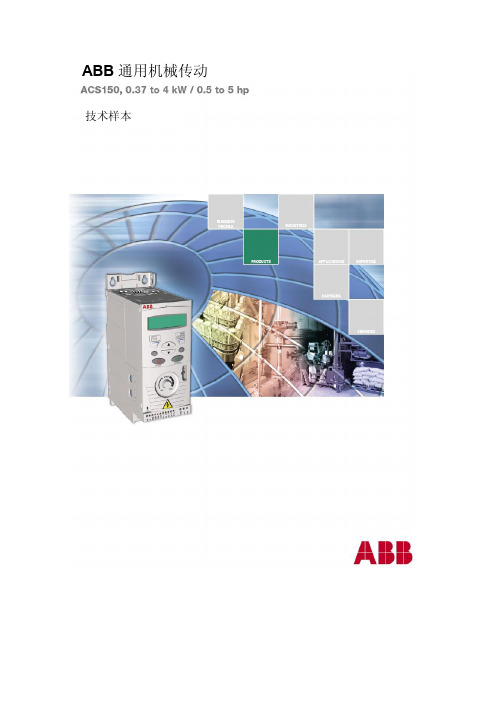
ABB 通用机械传动 技术样本特性 优点 备注FlashDrop传动设置及调试更加快速、容易, 可用于批量制造。
新型、快速、安全、无忧的方法, 无需加电。
专利技术。
固定式控制盘 具有舒适、耐用接口的简单传动。
具有清晰的 LCD 显示器、背景灯光以及按钮的集成控制面板。
固定式电位器直观的速度设定。
集成的电位器。
设定值显示在控制 面板上。
集成EMC 滤波器 无需外部滤波器。
第二环境滤波器标配,符合 IEC 618003。
内置制动斩波器 降低成本,节省空间并简化接线。
100%制动性能。
灵活的安装方式优化的布局以及有效的机柜空间利 用率。
螺钉、DIN 导轨、侧面、并排安装 方式。
统一的高度和厚度。
有涂层的电路板寿命更长且减少维护。
防潮和防尘标配。
ABB 通用机械传动应用 n 风机 n 泵 n 门控n 物料输送 n 传送带ABB 通用机械传动ABB 通用机械传动是专为机械制造 行业所设计的。
它可以通过可选件的优化 组合最大范围的满足机械行业的要求。
亮点n FlashDrop n 固定式控制盘 n 固定式电位器 n 集成EMC 滤波器 n 内置制动斩波器n 灵活的安装方式 n 有涂层的电路板技术规格及控制接线电网连接电压及功率范围单相,200 至 240 V ±10%0.37 至 2.2 kW三相,200 至 240 V ±10%0.37 至 2.2 kW三相,380 至 480 V ±10%0.37 至 4 kW频率 48 至 63 Hz功率因数 0.98电机连接电压 3 相,0 至输入电压频率 0 至 500 Hz连续负载能力额定输出电流 I2N(最高环境温度40ºC 时,恒转矩应用)过载能力每十分钟允许一分钟的(最高环境温度 1.5 x I2N 重载应用。
40ºC 时) 允许 2 秒钟的1.8 x I2N 起动应用。
开关频率缺省 4 kHz可选 4 kHz,8 kHz,12 kHz加速时间 0.1 至 1800 秒减速时间 0.1 至 1800 秒制动内置制动斩波器标配环境要求环境温度 10 至 40ºC (14 至 104ºF),无结霜50ºC (122ºF),10% 降容海拔高度输出电流 0 至 1000 m不需要降容, 1000m至2000m范围内, 每升高100m降容1% 相对湿度低于 95% (无冷凝)防护等级 IP 20 /可选 NEMA 1 柜体柜体颜色 NCS 1502Y, RAL 9002,PMS 420 C污染级别 IEC72133无导电性粉尘运输时 Class 1C2 (化学气体)Class 1S2 (固体颗粒)储存时 Class 2C2 (化学气体)Class 2S2 (固体颗粒)运行时 Class 3C2 (化学气体)Class 3S2 (固体颗粒)电抗器交流输入电抗器外部可选件用以减少部分负载中的 THD( 总谐波畸变 ) 并符合EN6100032交流输出电抗器外部可选件电机电缆可更长可编程控制连接1 路模拟输入电压信号 0 (2)至 10 V,R in > 312 kΩ电流信号 0 (4)至 20 mA, R in = 100 Ω分辨率 0.1%精度 ±1%辅助电压 24 V DC ±10%,最大 200 mA5 路数字输入 12 至 24 V DC 内部或外部供电,PNP 及 NPN 类型,脉冲序列0 至 16 kHz输入阻抗 2.4 kΩ1 路继电器输出型号 NO + NC最大开关电压 250 V AC/30 V DC最大开关电流 0.5 A/30 V DC;5 A/230 V AC最大连续电流 2 A rms产品符合的标准低压规程 73/23/EEC 及补充规定机械规程 98/37/ECEMC 规程 89/336/EEC 及补充规定质量保证体系 ISO 9001环境体系 ISO 14001UL,cUL,CE,CTick 及 GOST R 认证EMC (根据 EN618003之规定)第二环境滤波器,电缆长度为 30 m时无限制销售,内置型 标配电缆屏蔽层需在信号端接地电缆屏蔽层需在信号端接地DI配置PNP 连接DI配置NPN 连接额定值、型号、电压及结构额定值 型号代码 P N kW P N hp I 2N A外形规格单相电压 200-240 V 0.37 0.5 2.4 ACS150-01X-02A4-2 R00.75 1 4.7 ACS150-01X-04A7-2 R1 1.1 1.5 6.7 ACS150-01X-06A7-2 R1 1.5 2 7.5 ACS150-01X-07A5-2 R2 2.2 3 9.8 ACS150-01X-09A8-2 R2 三相电压 200-240 V 0.37 0.5 2.4 ACS150-03X-02A4-2 R0 0.55 0.75 3.5 ACS150-03X-03A5-2 R0 0.75 1 4.7 ACS150-03X-04A7-2 R1 1.1 1.5 6.7 ASC150-03X-06A7-2 R1 1.5 2 7.5 ACS150-03X-07A5-2 R1 2.2 3 9.8 ACS150-03X-09A8-2 R2 三相电压 380-480 V 0.37 0.5 1.2 ACS150-03X-01A2-4 R0 0.55 0.75 1.9 ACS150-03X-01A9-4 R0 0.75 1 2.4 ACS150-03X-02A4-4 R0 1.1 1.5 3.3 ACS150-03X-03A3-4 R1 1.5 2 4.1 ACS150-03X-04A1-4 R1 2.2 3 5.6 ACS150-03X-05A6-4 R1 3 4 7.3 ACS150-03X-07A3-4 R1 4 5 8.8 ACS150-03X-08A8-4R1IP 20 UL开放式NEMA 1 外形规格 H1 mm H2 mm H3 mm W mm D mm 重量kg H4 mm H5 mm W mm D mm 重量kg R0 169 202 239 70 142 1.1 257 280 70 142 1.5 R1 169 202 239 70 142 1.3 257 280 70 142 1.5 R21692022391051421.52572821051421.5型号代码右表第四列的型号代码清楚地表明了 传动的功率额定值和外形规格。
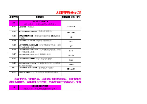
ACS800变频器参数
DI4 3.00 s 3.00 s
10 2.50 s 0.0 ms 0.00 s 100.0% NO 8 ms
25.05 CRIT SPEED 2 HIGH (定义危险速度范围 1 的终点)
26
MOTOR CONTROL
26.01 FLUX OPTIMIZATION (激活 / 取消磁通优化功能)
LOCAL LOCK(使进入本地控制模式的键失效)
16.07 16.08 16.09
20
20.01
PARAMETER SAVE(存储有效参数值到永久性存储器 中)
RUN ENA PTR(定义参数 16.01 中 PAR 16.08 选项的变 量或常量)
CTRL BOARD SUPPLY(定义控制板的电源)
出) INVERT AO1(模拟输出 AO1 取反功能)
MINIMUM AO1(定义模拟输出信号 AO1 的最小值)
FILTER AO1(定义模拟输出信号 AO1 的滤波时间)
SCALE AO1(标定模拟输出信号 AO1)
15.06 15.07
ANALOGUE OUTPUT2(选择一个传动信号到模拟输 出)
STOP FUNCTION(选择电机停止模式)
21.1 ZERO SPEED DELAY ( 给零速延时功能定义延时时间)
NOT SEL OFF DONE 0
INTERNAL 24V
(calculated) (calculated) 随型号而定
3 ON ON
AUTO 500.0 ms COAST
22
PASS CODE(输入开锁密码)
16.04
FAULT RESET SEL(选择故障复位信号的信号源)
SPEED NO 0 mA 0.10 s 1
PMAC800系列产品使用手册

适用范围 重要电动机的综合保护 普通电动机的综合保护 普通电动机的电流保护 普通电动机的电流保护
SCT型号 SCT150 SCT200 SCT300 SCT400
电动机额定电流 150A及以下 200A及以下 300A及以下 400A及以下
PMAC系列产品主要特点
● PMAC系列智能电动机保护控制装置是针对低压电动机控制系统设计,超小外型尺寸,适用于GCK、GCS、GGD、 MNS等各种抽出式(包括1/4抽屉)、固定式及混合式的柜型安装。具有方便安装、布局合理、维护方便、节约电 缆、安全可靠等多种优点;
● 全面采用嵌入式 SOC(System On Chip 片上系统)设计、32 位 DSP(Digital Signal Processing 数字信号处理 技术和冗余现场总线技术,交流采样采用优化全波 FFT(Fast Fourier Transform 快速傅立叶变换)技术,软件 采用模块化、高抗干扰设计;
绝缘性能 绝缘电阻 工频耐压 冲击电压 耐湿热
各电气回路之间>20MΩ 各电气回路对地>20MΩ 各电气回路之间2KV/50Hz 1Min 各电气回路对地2KV/50Hz 1Min 各电气回路之间1.2/50μs, 5000V 各电气回路对地1.2/50μs, 5000V 遵循GB/T 2423.9-2001
PMAC系列智能电动机保护控制装置主要用于690V以下低 压电动机控制系统,对电动机的过负荷、短路、超长时间启 动、堵转、不平衡、接地、欠压、过压、工艺联锁等故障引 起的危害予以保护,并集合全面的三相电量测量/显示、数 字输入/输出与网络通讯于一身。每个装置具有多种综合电 力参数测量功能,既可单独作为电测仪表使用,亦可作为电 力综合自动化监控系统之前端,可实现测量、监视、保护、 控制等综合功能,通过其标准的RS-485通讯接口及双绞线网 络与监控系统通信,轻松实现数据的远方管理及“四遥”功 能。
ELTRA CS-800 碳硫测定仪 翻译

CS-800碳硫检定仪CS-800结合最新燃烧技术。
为在铁、铸钢、铜、合金、矿砂、水泥、陶瓷、碳化物、矿石、沙子、玻璃等存在的碳硫做迅速鉴定而设计。
CS-800 可以提供四个以上的独立红外吸收池。
每个电池有适当的长度和灵敏度可以独立的筛选提供碳硫高低水平分析的最佳精确度。
CS-800微型控制器,一个具有自动调零和自动范围控制的高频感应炉和固体形态红外检测器。
操作技巧样品在陶瓷坩埚电子天平上准确称重后,压制的关键,样品的重量是自动传输到电脑中。
如有需要,样品重量也可以手动输入。
压制开始的关键分析时间是50秒。
分析过程指示是确保容易和可信的显示出来。
CS-800样品入门只需最小的维护要求。
微软XP或视窗2000电脑控制综合分析控制和简单操作由电脑软件提供给分析员。
从主菜单获取更多关于软件的信息。
红外吸收池CS-800的红外吸收池不需要任何手动调零来调节。
红外吸收池的调零和灵敏度调节是由电子长期自动控制。
检测器利用固体形态传感器与红外过滤器相结合。
传感器不是气体填充的,以此消除了由于气体泄漏带来的长期问题。
CS-800可以装备4个以上独立红外吸收池。
所有4快电池的长度可以独立利用,为每个客户的目的分析水平达到最大精确度。
每个电池可在红外体安装长度为1毫米到320毫米之间。
电流控制气流系统中的要素是电流控制。
由机械控制排除所知不利因素提供一个稳定气流。
预热坩埚对高频感应炉的陶瓷坩埚可以在高温熔炉HTF-540中预热。
预热减少坩埚的无用值。
这种在极低百万分率范围内分析中很重要。
坩埚被插入炉管中,直至需要在管内预热残留物。
每次坩埚需要,新的就要插入管内,并且预热坩埚从另一只炉管末端跳出。
建议预热温度在1250度和1350度之间。
自动装载CS-800可以提供自动样品装载系统。
装载系统或会在以后更新。
与许多其他自动装载不同,ELTRA系统可以容纳届时未被容纳操作的130种样品。
有需求的话,可以为更多坩埚提供装载器。
ASCO样本_图文.

自动转换开关ATSASCO(Automatic Switch Company 美国自动开关公司创立于1888年,于1920年研发制造出第一台自动转换开关,经由不断的创新与发展,一直是电力界自动转换开关产品的首选,是ATS 业界领导者。
右图为ASCO 全球总部及主要生产工厂,位于美国新泽西州Florham Park,拥有超过1300名员工,此工厂每年制造及运送数以万计的ATS 至全球各地。
全球总部-Florham Park, 美国新泽西州当您了解越多,您会更加坚定选择ASCO 提供多元化产品及解决方案以符合各种对紧急电源转换应用的要求: ◆自动转换开关ATS◆不停电闭合转换开关CTTS◆延时转换开关DTTS◆维修时仍可继续供应电力的旁路隔离抽出型转换开关ATB ,ACTB◆固态电子式快速转换开关STS◆闭路式线性加卸载转换开关SLTS◆中压转换开关MV ATS ,MVCTTS◆多电源转换系统◆发电机并联系统◆紧急电力管理系统 2000A 含维护旁路自动转换开关◆照明控制接触器◆瞬时浪涌电压突波抑制器全球销售与服务网络ASCO 产品销售及服务网遍布全球,ASCO 自动转换开关为强制认证(CCC合格产品、UL1008认证合格产品,是全球第一家取得CE,IEC60947-6-1及Kema Keur 认证合格的自动转换开关,符合NFPA 20,70, 99,110,IEEE 241,446及NEMA ICS10-1993(ICS2-447 法规标准。
自动转换开关提供最佳可靠度◆真正PC级自动转换开关,GB/T 14048.11、UL1008及IEC60947-6-1认证的合格产品◆适用于各类型负载,可使用于最复杂负载类型AC-33A ◆带载转换及耐受故障电流能力高,方便保护协调设计及设定◆线圈激磁型转换开关,转换速度快且稳定◆电气操作,机械保持触头闭合◆电气及机械联锁,保证只接触一路电源供电,避免双边电源不供电或双路电源短路◆具灭弧触头及灭弧室,保护主触头,有足够灭弧距离,保证明显断开点◆大电流ATS静主触头为分片式设计,保证最佳接触面积避免过热,并具有自我清洁功能◆百分之百电流额定◆不需外接触独立控制电源,降低故障率◆可由正面检视维修◆转换速度低于100ms◆微处理机控制器,控制精密度高◆可搭配同相位侦测器进行同相位转换◆可搭配中性线重叠转换,避免转换过程产生瞬间异常电压◆可搭配通讯模块,远程监控ATS状态重要负载供电需要ATS 医院、电子半导体业、商业大楼及工业厂房计算机数据处理中心,电信通讯机房石化工业及制造业300系列自动转换开关ATS◆适用于商业、工业及紧急重要的供电场所◆GB/T 14048.11、UL1008及IEC60947-6-1认证合格产品◆2、3、4极,适用于120V-600V ,单相及三相系统,30A-3200A ,50/60Hz◆PC 级ATS 适用于各类负载及AC-33A◆自动转换开关采用先离后接转换模式,转换过程负载短瞬间停电,有明显断开点◆转换机构电力来自于即将投入端电源,不需额外控制电源,减少故障率◆简单明了的盘面控制及显示面板,LED 灯号显示开关位置及电源状态,并含测试及延时取消开关◆附发电机每周定时启动测试定时器,可设定有载或无载测试,若有必要也可取消此设定◆有时正常及紧急电于瞬间压降或瞬间停电后马上复电,一般ATS 在此状况下会做不必要的频繁转换; ASCO300系列ATS 可以延时设定忽略此种电力问题,使ATS 不作无谓转换200A ATS ,屋外型外箱UL1008耐受短时电流及带载转换闭合额定能力对称电流值(A/RMS ATS 电流(A 以熔丝保护时可达(A值以断路器保护时可达(A值 30 100,000 10,000 70-200 200,000 22,000 230 100,000 22,000 260,400 200,000 42,000 600 200,000 50,000 800,1000,1200 200,000 65,000 1600,2000 200,000 85,000 2600,3000,3200 200,000 100,000300系列微处理机控制器ASCO Group 1微处理机控制器适用于300系列自动转换开关,是一台高可靠度控制器,功能涵盖电压、频率及延时设定,控制功能的启动与取消,并具通信功能。
医学--ELSD800操作手册
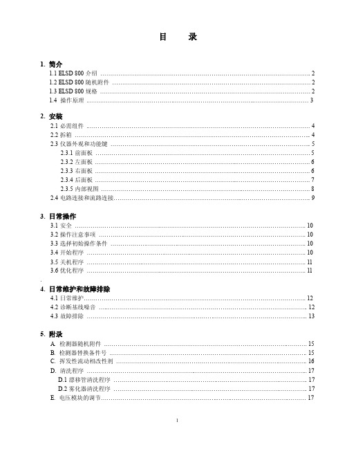
目录1. 简介1.1 ELSD 800介绍 (2)1.2 ELSD 800随机附件 (2)1.3 ELSD 800规格 (2)1.4 操作原理 (3)2. 安装2.1必需组件 (4)2.2拆箱 (4)2.3仪器外观和功能键 (5)2.3.1前面板 (5)2.3.2左面板 (6)2.3.3右面板 (6)2.3.4后面板 (7)2.3.5内部视图 (8)2.4电路连接和流路连接 (9)3. 日常操作3.1安全 (10)3.2操作注意事项 (10)3.3选择初始操作条件 (10)3.4开始程序 (10)3.5关机程序 (11)3.6优化程序 (11).4. 日常维护和故障排除4.1日常维护 (12)4.2诊断基线噪音 (12)4.3故障排除 (13)5. 附录A. 检测器随机附件 (15)B. 检测器替换备件号 (15)C. 挥发性流动相改性剂 (16)D. 清洗程序 (17)D.1漂移管清洗程序 (17)D.2雾化器清洗程序 (17)E. 电压模块的调节 (17)1. 简介1.1 ELSD 800介绍Alltech 800型蒸发光散射检测器(简称ELSD 800),是对于使用传统HPLC方法中的紫外和示差检测器所难以检测的化合物的理想HPLC检测器。
不同于示差检测,ELSD 800与梯度洗脱相容,对室内温度变化不敏感,且消除溶剂前沿峰,灵敏度比示差检测器高很多。
不同于低波长紫外检测器ELSD 800在急变梯度时不受基线漂移的困扰,并且不要求被检测化合物带有发色团。
Alltech ELSD 800是设计用于高效液相色谱系统的,能分析任何挥发性低于流动相的化合物。
ELSD 800成功地用于分析碳水化合物,药物,脂类,甘油三脂,未衍生的脂肪酸和氨基酸,组合化学库。
1.2 ELSD 800随机附件Alltech 800型ELSD必须包括以下部件:∙ELSD 800检测器主机∙ELSD 800操作手册∙电源线∙信号线∙备用保险丝(6A for 110V, 3A for 220V)∙开口扳手,3/8"⨯7/16"∙开口扳手,1/4"⨯5/16"∙六角球型螺丝刀,3/32"(长柄)∙六角球型螺丝刀,3/32"(短柄)∙Teflon管,10'⨯1/8"∙1/8"铜螺帽和卡套分流废液收集装置:∙3/8"不锈钢螺帽和Teflon卡套∙Tygon排水管,4'⨯3/8"OD∙500mL分流废液收集瓶∙3/8"不锈钢排废管,附带不锈钢螺帽和卡套排气冷阱收集装置:∙收集瓶,500mL,带塞子∙排气管(检测器到冷阱),3ft∙排气管(冷阱到通风橱),20ft∙排气口接头,SS∙铅环1.3 ELSD 800规格1.4 操作原理蒸发光散射检测器的独特检测原理分为三个步骤:首先将柱洗脱液雾化形成气溶胶,然后在加热的漂移管中将溶剂蒸发,最后余下的不挥发性溶质颗粒在光散射检测池中得到检测。
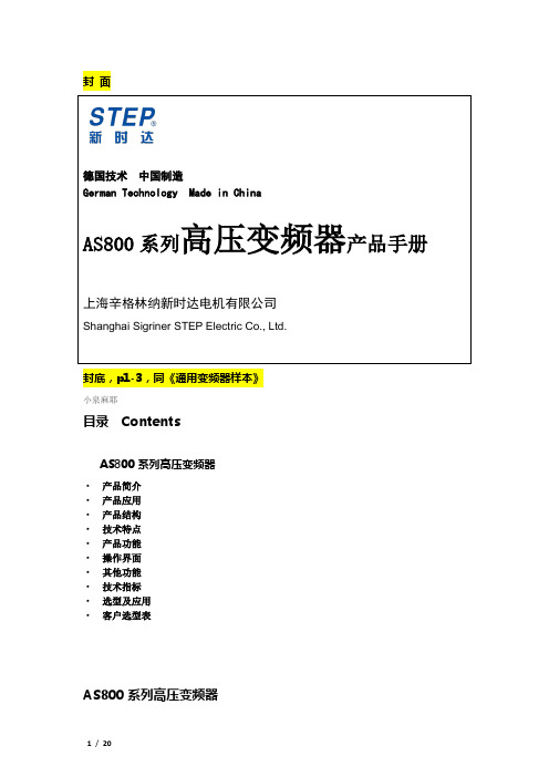
AS800高压变频器样本-20140319
280
350
34
AS800-0280-T06-PAA
变频器系统的选型
平方转矩负载
负载类型:风机、水泵、油泵等,选型时按电机工频运行的最大电流选择变频器;一台变频器同时拖动多台电机,按电机额定电流和的1.25倍选择变频器。
恒功率负载
负载类型:轧钢机、造纸机等,按电机额定电流的1.25倍选择变频器。
恒转矩负载
负载类型:传送带、搅拌机、挤压机等摩擦类负载;起重机、提升机等重力负载;空气压缩机、罗茨鼓风机、球磨机、往复式注塞泵等,变频器输出电流大于电机最大运行电流的1.25倍选择变频器(一拖二时按电机电流和的1.25倍选择)。
·变压器柜:变压器为干式移相变压器,H级绝缘,系统最高温度可达180℃,一次侧±5%抽头可调,变压器采用江苏中电或新华都品牌。
移相变压器作用:减少谐波干扰,提高功率因数。
·旁路柜:手动旁路柜系统的功能:变频器故障退出运行后,手动将电机切换到工频电网运行,检修安全
自动旁路系统旁路主要功能:在变频器故障的时候将电机直接投入到工频电网,以保证生产的连续性,自动切换的过程对电网及电机无冲击。
输出电流/A
产品型号
整机风量(m3/h)
变频器尺寸(mm)
总重量(T)
250
300
58
AS800-0250-T03-PAA
9000
2600*1500*2667
4
280
350
67
AS800-0280-T03-PAA
9000
2600*1500*2667
4
300
375
72
AS800-0300-T03-PAA
正常减速曲线 自均衡技术减速曲线
ACS800选型样本

/motors&drives ..................................... 51
3ABD00018063 REV A CN 20.09.2005
1 2
3 4
5 6
7 8 9
标准应用软件 ................................. 39 可选的应用软件
不同应用的控制解决方案 .................... 40 DriveSize .................................................................. 43 DriveAP .................................................................... 44 DriveWindow 2 .......................................................... 45 DriveWindow Light 2 .................................................. 46 DriveOPC .................................................................. 47 表格 ......................................... 48
逆变器
设计图纸和接线图。由于模块的灵活性和可编程能力使
得它可以满足不同工业领域的不同的需求。
逆变器
ACS800-04单 传 动模 块 ACS800-04单元是集成在用户设计的柜体里的单传动 模块产品。 每个交流单传动单元包含整流部分、直流母线部分和 逆变部分。
ABB ASC800参数设置 (仅供参考)

以下均为端子控制启动、停止、转向、转速的参数设置。
仅供参考!实际情况可根据端子的实际接法和说明书去调试(电流控制转速AI2 电压控制转速AI1)
1、10.01 设为17 定义外部控制地1(EXT1) 用于起动、停机和转向命令的连接和信号源。
DI1 F DI2 R
2、10.03 设为1固定为正向允许改变电机的转向,或固定转向。
FORW ARD
3、11.01 设为1 速度给定值,单位rpm。
( 如果参数99.04 值为SCALAR,则为频率给定值(Hz)。
)
4、11.02设为7指定EXT1为当前控制地。
控制信号源由10.01和11.03定义。
5、11.03 设为3 选择外部给定REF1 的信号源。
AI2(根据现场的接线情况进行设定)
6、11.04 设为200 定义外部给定REF1 的最小值( 绝对值)。
相当于所用的信号源的最小设定值。
200rpm
7、11.05 设为1450 定义外部给定REF1 的最大值( 绝对值)。
相当于所用的信号源的最大设定值。
1450 rpm
8、13.06 、设为2 即4mA 定义模拟输入AI2的最小值。
当用作给定值时,其值对应于最小给定设定值。
9 、13.07设为1 即20mA 定义模拟输入AI2的最大值。
当用作给定值时,其值对应于最大给定设定值。
例如: 如果AI1 作为外部给定REF1 的信号源,其值对应于参数11.05 的值
10、21.03 选择电机停止模式。
COAST
路云和月
2014年五月份。
1.2数据编码课件高中信息技术粤教版必修12

练习3:一段画面尺寸为600×400像素,24位彩色的NTSC制式视频,时长为5分钟, 若没有经过压缩,则存储容量大约为( )。
A. 87MB
B. C. 800MB
2.1GB
D. 6.1GB
NTSC视频每秒30帧画面
1B(字节) = 8bit(位), 1KB (千字节) = 1024B, 1MB (兆字节) = 1024KB, 1GB (千字节) = 1024MB, 1TB (万亿字节) = 1024GB.
录制音乐 计算机存储音频
声音编码
声音编码
声音存储空间=采样频率×量化位数×声道数×时间÷8
(B)
(Hz)
(s)
声音存储空间=采样频率×量化位数×声道数×时间÷8
(B)
(Hz)
(s)
例:采样频率为44.1KHz、量化位数为16位的立体声,1秒声音所需字节数为:
= 44.1×1000(Hz)×16×2×1(s)÷8 = 176400(B)
A. 3MB
B. 24MB
C. 768MB
D. 3073MB
图像存储空间=图像分辨率×图像量化位数÷8
(B)
像素数(长×宽)
1B(字节) = 8bit(位), 1KB (千字节) = 1024B, 1MB (兆字节) = 1024KB, 1GB (千字节) = 1024MB, 1TB (万亿字节) = 1024GB.
- 01 -
模拟信号 与
数字信号
- 02 -
文字编码
- 03 -
图像编码 和
声音编码
S TA R T
数据编码
S TA R T
- 01 -
模拟信号 与
数字信号
- 02 -
IMMAGE800标准操作文件

IMMAGE800特定蛋白分析仪SOP仪器序列号:1111111起草人: 日期:修改人:日期:Beckman Coulter IMMAGE 800 特定蛋白分析仪标准操作文件一、目的:规范IMMAGE 800的操作程序,确保临床特定蛋白检验结果准确二、适用范围:适用于标本的临床特定蛋白测定三、方法原理:速率散射法:此时90散射信号会相应增强。
速率透射法:在0的光强度会减弱。
这一减弱会转变为增强的光信号:光信号 = - Log10 (光强度).系统监控装置每5秒钟监测一次散射光信号。
在反应结束时,仪器会自动计算光信号变化的速率。
四、检测项目:请参考检测项目SOP五、运行条件:5.1 运行环境为保证仪器的正常运行,仪器必须在满足下列条件和维持相应环境的情况下使用:5.1.1灰尘少、换气良好的环境。
5.1.2避免阳光直接照射。
5.1.3仪器仅供室内使用,环境温度为18℃至32℃,湿度为20-85%,海拔最高为1280米。
5.1.4仪器的工作电源为220V AC、50/60 HZ。
有保护性接地。
5.1.5仪器附近没有发射高频的机械(离心机、放电装置等)5.2 安全条款5.2.1在使用对人体有危险或发生感染的样品时,请使用橡胶手套,不要直接接触。
5.2.2在仪器上面和周围不要使用可燃性危险品、避免引起火灾和爆炸5.2.3在仪器运转过程中,勿触及样品针、试剂针、搅拌棒、反应容器、清洗机构等,避免人身伤害。
5.2.4仪器的操作、保养应按规定的程序进行。
5.2.5在电源开关处于on状态下接触线路板有触电危险。
5.2.6禁止打开仪器前右侧、背面及侧面面板,会损害线路板。
5.2.7请勿用肉眼直视光源灯光,否则会伤害眼睛。
六、开关机程序: 6.1 开机1.打开打印机、显示器 2.打开操作电脑 3.打开仪器开关 6.2关机1.当机器在 Standby 状态 在 择2.等待一会,当屏幕出现Shutdown completedPower off the immage and Reboot the system 时,关仪器、操作电脑、显示器及打印机。
ACS800参数设置

ACS800参数设置
不带电机测试30.16改成no
控制方式99.04改成sar
测试制动680v制动打开R+ 输出
20.05改成on 27.01改成on 42.01改成on
远程本地无法切换
你先确认参数是否被锁,如果参数被锁就需要16.03输入密码358开锁,如果参数没锁只要1606选择OFF就行
如何将数据从传动单元上传至控制盘
在下载之前须进行上传;
•确认目标传动单元的程序版本与源传动单元的程序版本相同
•将控制盘从一个传动单元移开之前,确认控制盘处于远程控制模式状态(可以通过LOC/REM 键进行改变)。
•下载之前传动单元必须处于停止状态。
如何将数据从控制盘下载到传动单元
请仔细阅读上节“如何将数据从一个传动单元上传至控制盘。
”中的注意事项。
ASTM A800&A800M-2001 奥氏体合金钢铸件中铁素体含量的估算
Designation:A800/A800M–01Standard Practice forSteel Casting,Austenitic Alloy,Estimating Ferrite Content Thereof1This standard is issued under thefixed designation A800/A800M;the number immediately following the designation indicates the year of original adoption or,in the case of revision,the year of last revision.A number in parentheses indicates the year of last reapproval.A superscript epsilon(e)indicates an editorial change since the last revision or reapproval.1.Scope1.1This practice covers procedures and definitions for estimating ferrite content in certain grades of austenitic iron-chromium-nickel alloy castings that have compositions bal-anced to create the formation of ferrite as a second phase in amounts controlled to be within specified limits.Methods are described for estimating ferrite content by chemical,magnetic, and metallographic means.1.2The grades covered by this practice are:CF-3,CF-3A, CF-8,CF-8A,CF-3M,CF-3MA,CF-8M,CF-8C,CG-8M,and CH-10.1.3The values stated in either inch-pound units or SI units are to be regarded separately as standard.Within the text,the SI units are shown in brackets.The values stated in each system are not exact equivalents;therefore,each system must be used independently of the bining values from the two systems may result in nonconformance with the practice.1.4This standard does not purport to address the safety concerns,if any,associated with its use.It is the responsibility of the user of this standard to establish appropriate safety and health practices and determine the applicability of regulatory limitations prior to use.2.Referenced Documents2.1ASTM Standards:A351/A351M Specification for Castings,Austenitic,Aus-tenitic–Ferritic(Duplex),for Pressure–Containing Parts2 A370Test Methods and Definitions for Mechanical Testing of Steel Products3A799/A799M Practice for Steel Castings,Stainless,In-strument Calibration,for Estimating Ferrite Content2A941Terminology Relating to Steel,Stainless Steel,Re-lated Alloys,and Ferroalloys4E38Methods for Chemical Analysis of Nickel-Chromiumand Nickel-Chromium-Iron Alloys5E353Test Methods for Chemical Analysis of Stainless, Heat-Resisting,Maraging,and Other Similar Chromium-Nickel-Iron Alloys6E562Practice for Determining V olume Fraction by Sys-tematic Manual Point Count72.2Constitution Diagrams:Schoefer Diagram for Estimating Ferrite Content of Stain-less Steel Castings(1980revision)8Schaeffler Diagram for Estimating Ferrite Content of Stain-less Steel Weld Metal9DeLong Diagram for Estimating Ferrite Content of Stainless Steel Weld Metal102.3American Welding Society Specification:AWS A4.2,Procedures for Calibrating Magnetic Instru-ments to Measure the Delta Ferrite Content of Austenitic Stainless Steel Weld Metal113.Terminology3.1Definitions:3.1.1ferrite—the ferromagnetic,body-centered,cubic-microstructural constituent of variable chemical composition in iron-chromium-nickel alloys.This may be formed upon solidi-fication from the molten metal(delta ferrite)or by transforma-tion from austenite or sigma phase on cooling in the solid state (alpha ferrite).3.1.2ferrite content—the proportion of total volume of an iron-chromium-nickel alloy present as the ferrite phase.3.1.3ferrite number—the ferrite content expressed as an arbitrary number based on the magnetic response of the alloy in a weld deposit.3.1.4ferrite percentage—the ferrite content expressed as a volume percent.1This practice is under the jurisdiction of ASTM Committee A01on Steel, Stainless Steel,and Related Alloys and is the direct responsibility of Subcommittee A01.18on Castings.Current edition approved Mar.10,2001.Published May2001.Originally published as A800–st previous edition A800/A800M–91(Reapproved 1997).2Annual Book of ASTM Standards,V ol01.02.3Annual Book of ASTM Standards,V ol01.03.4Annual Book of ASTM Standards,V ol01.01.5Discontinued;see1988Annual Book of ASTM Standards,V ol03.05.6Annual Book of ASTM Standards,V ol03.05.7Annual Book of ASTM Standards,V ol03.01.8Appendix of this practice.9Metal Progress Data Book,American Society for Metals,Mid June1977,p.161.10Welding Journal,American Welding Society,V ol38,No.7,July1973,p.293–s.11Available from the American Welding Society,P.O.Box351040,550N.W.LeJeune Rd.,Miami,FL33135.1Copyright©ASTM International,100Barr Harbor Drive,PO Box C700,West Conshohocken,PA19428-2959,United States.3.1.5heat treatment—the definitions in Terminology A941 are applicable to this practice.4.Significance and Use4.1The tensile and impact properties,the weldability,and the corrosion resistance of iron-chromium-nickel alloy castings may be influenced beneficially or detrimentally by the ratio of the amount of ferrite to the amount of austenite in the microstructure.The ferrite content may be limited by purchase order requirements or by the design construction codes gov-erning the equipment in which the castings will be used.The quantity of ferrite in the structure is fundamentally a function of the chemical composition of the alloy and its thermal history.Because of segregation,the chemical composition, and,therefore,the ferrite content,may differ from point to point on a casting.Determination of the ferrite content by any of the procedures described in the following practice is subject to varying degrees of imprecision which must be recognized in setting realistic limits on the range of ferrite content specified. Sources of error include the following:4.1.1In Determinations from Chemical Composition—Deviations from the actual quantity of each element present in an alloy because of chemical analysis variance,although possibly minor in each case,can result in substantial difference in the ratio of total ferrite-promoting to total austenite-promoting elements.Therefore,the precision of the ferrite content estimated from chemical composition depends on the accuracy of the chemical analysis procedure.4.1.2In Determinations from Magnetic Response—Phases other than ferrite and austenite may be formed at certain temperatures and persist at room temperature.These may so alter the magnetic response of the alloy that the indicated ferrite content is quite different from that of the same chemical composition that has undergone different thermal treatment. Also,because the magnets or probes of the various measuring instruments are small,different degrees of surface roughness or surface curvature will vary the magnetic linkage with the material being measured.4.1.3In Determinations from Metallographic Examination—Metallographic point count estimates of ferrite percentage may vary with the etching technique used for identification of the ferrite phase and with the number of grid points chosen for the examination,as explained in Test Method E562.4.2The estimation of ferrite percent by chemical composi-tion offers the most useful and most common method of ferrite control during melting of the metal.4.3For most accurate estimate of ferrite percent,a quanti-tative metallographic method should be used.5.Ordering Information5.1Orders for material to this practice should include the following as required:5.1.1Applicable ASTM product specification or other docu-ment covering product requirements,5.1.2Alloy grade,5.1.3Required ferrite content range,in volume percent,of the castings afterfinal heat treatment.Also,if desired by the purchaser,required ferrite content range,in ferrite number,for weld deposits(Note1)as deposited,and5.1.4Supplementary requirements,if any,desired.N OTE1—There may be a substantial decrease in the ferrite content of weld deposits after solution heat treatment in comparison with the as-deposited value.6.General Caution6.1In specifying ferrite content as required in5.1.3,the purchaser should not set limits that conflict with applicable material specification requirements:for example,a maximum limit of10%ferrite for Grade CF-3A in Specification A351/ A351M for which the minimum tensile strength requirement is 77ksi[530MPa].6.2When Supplementary Requirement S1is specified,the purchaser should set ferrite content limits that are compatible with the measuring instrument to be used.7.Estimation of Ferrite Content7.1Estimation in the base metal of the casting by chemical composition in accordance with the Schoefer diagram(see Appendix X1):7.1.1A chemical analysis of the heat from which the castings are poured shall include the following elements whether or not required by the chemical requirements of the product specification:carbon,manganese,silicon,chromium, nickel,molybdenum,columbium,and nitrogen.7.1.1.1Upon written agreement between the purchaser and the producer,an estimated nitrogen content may be reported instead of an amount determined by analysis of the specific heat if actual chemical analyses have been made for nitrogen in a sufficient number of heats of the same alloy type,produced by the same melting practice,to establish the average nitrogen content to be expected.7.1.2The ferrite content of the casting shall be estimated from the central line of the diagram at the composition ratio of “chromium equivalent”(Cr e)to“nickel equivalent”(Ni e) determined from the following formula:~Cr~%!11.5Si~%!11.4Mo~%!1Cb~%!24.99!/~Ni~%!130C~%!10.5Mn~%!126~N20.02%!12.77!5~Cr e!/~Ni e!7.1.3When a product analysis is made by the purchaser,it shall include the elements listed in7.1.1.If a comparison is made of ferrite content estimated from a product analysis performed by the purchaser,with that estimated from the heat analysis(see7.1.1),the reproducibility data in the precision statements of Test Methods E353shall be used as a guide.7.1.3.1Methods E38or Test Methods E353,as applicable, shall be used as referee chemical analysis methods.7.2Estimation in weld deposits by chemical composition in accordance with the Schaeffler or DeLong diagrams:7.2.1The ferrite content shall be estimated(a)from the deposit chemical analysis included on the electrode manufac-turer’s certified material test report,or(b)from chemical analysis of a weld deposit pad made by the casting manufac-turer.7.3Estimation of ferrite content in heat,product,or weld metal may be made by the magnetic response or metallo-graphic methods by imposition of Supplementary Require-ments S1or S2,respectively.8.Acceptance Standards8.1Conformance with the required ferrite content range specified in5.1.3as indicated by the estimation procedure of 7.1and7.2shall be the basis for acceptance of material supplied under this practice unless other methods of estimation are ordered as supplementary requirements,in which case the supplementary requirement shall be the basis of acceptance.8.2If lack of conformance with the ferrite content range specified in5.1.3is indicated by a product analysis made by the purchaser(7.1.3)and by a referee analysis as provided in 7.1.3.1,rejection of material shall be subject to the tests of7.3 as established by written agreement between the manufacturer and the purchaser.9.Certification9.1The manufacturer’s certification shall be furnished to the purchaser stating that the material was sampled and tested in accordance with the specification(including year date)and was found to meet the requirements.9.2The test report shall contain the results of the actual chemical analyses required by7.1.1and7.2.1and the indicated ferrite content range.The estimates of ferrite content from magnetic measurements(S1)or from point counts(S2),or both,if ordered by the purchaser,also shall be reported.9.3The test report shall be signed by an authorized agent of the manufacturer.9.4The test report shall be furnished withinfive working days of shipment of the castings.10.Keywords10.1austenite;austenitic stainless steel;ferrite;Schoefer Diagram;steel castingsSUPPLEMENTARY REQUIREMENTSThe following supplementary requirements are for use when desired by the purchaser.They shall not apply unless specified in the order,in which event the specified methods of ferrite content estimation shall be employed by the manufacturer before shipment of the castings.S1.Estimation of Ferrite Content by Measurement of Magnetic ResponseS1.1The ferrite content of the heat from which the castings are poured shall be estimated from measurements made by primary or secondary instruments calibrated in accordance with the requirements of Practice A799/A799M.All measure-ments shall be made on material after the solution heat treatment required by the applicable product specification,or, if any subsequent solution heat treatment is employed,then after thefinal solution heat treatment.S1.1.1Location of measurements—base metal:S1.1.1.1Measurements shall be made on the unstrained ends of tension test specimens from the same heat as the castings represented.Measurements may be made either before or after performance of the tension test.If a tension test is not required by the applicable product specification,measurements may be made on a specimen cut from a keel block of a design in Fig.3of Test Methods and Definitions A370.S1.1.1.2When further specified,measurements shall be made on the base metal of the castings,or a specified sample of castings(not on weld repairs or other weld deposits),in locations designated on the design drawing or as otherwise agreed in writing between the purchaser and the manufacturer. S1.2The ferrite content of weld deposits shall be estimated from measurements made by primary or secondary instruments calibrated in accordance with the requirements of Specification AWS A4.2.All measurements shall be made on weld deposits as deposited.S1.2.1Location of measurements—weld deposits:S1.2.1.1Measurements shall be made on a weld pad depos-ited in accordance with the electrode specification.S1.2.1.2When further specified,measurements shall be made on repair or fabrication welds on castings in locations as agreed in writing between the purchaser and manufacturer.S1.3Number of Measurements—Six measurements shall be made at random in each designated location.For instruments having probes making two contacts with the surface being measured,a“measurement”shall consist of a pair of readings taken with the probe oriented on perpendicular axes.S1.4Surface Condition:S1.4.1The instrument magnet or probe and the surface to be measured shall be dry and cleaned prior to testing to remove any scale,grease,lint,or dirt that could affect the accuracy of measurement.S1.4.2Measurements shall be made more than0.25in.[6.350mm]from the edge of a surface.When measurements are made on a curved surface the radius of curvature must be greater than0.375in.[9.525mm].S1.5Acceptance Criteria:S1.5.1The average of the ferrite contents estimated from measurements in each designated location shall be within the limits stated in the order,and not more than two individual measurements shall indicate ferrite contents less than or in excess of these limits.S1.5.1.1If ferrite contents are estimated with an instrument that indicates for each measurement a value between an upper and a lower limit,more than one-half of all measurements shall be within the limits stated in the order.S1.5.2Should the requirements of S1.5.1not be met,a referee estimation of ferrite content may be made by the metallographic method of Supplementary Requirement S2that shall take precedence over the magneticmethod.S2.Estimation of Ferrite Content by Metallographic ExaminationS2.1The locations of specimens to be examined shall be specified on the drawing radiographic shooting sketch,or otherwise in writing by the purchaser.S2.2Specimens shall be prepared so that metallographic examination may be made on three orthogonal planes.S2.3The volume fraction of ferrite shall be estimated from the specimens by the point count practice recommended in Test Method E562.APPENDIX(Nonmandatory Information)X1.NOTES TO SCHOEFER DIAGRAMX1.1Fig.X1.1is applicable to alloys containing elements in the following ranges:Weight,% Carbon0.20maxManganese 2.00maxSilicon 2.00maxChromium17.0to28.0Nickel 4.0to13.0Molybdenum 4.00maxColumbium 1.00maxNitrogen0.20maxX1.2The Cr e/Ni e Composition Ratio necessary to produce alloy castings within a specified ferrite content range may be read from the diagram at the intersection of the central line with the desired ferrite percentage,or may be obtained from Table X1.1.Example:For a ferrite content of12%the composition ratio should be1.234.X1.3The estimated average ferrite content of castings may be read from the diagram at the intersection of the central line with the composition ratio calculated from the chemical composition of the heat from which they were poured.Because of errors in chemical analyses,the calculated ratio maydiffer FIG.X1.1Schoefer Diagram for Estimating the Average Ferrite Content in Austenitic Iron-Chromium-Nickel AlloyCastingsfrom the actual composition ratio and,as a result,the ferrite content may be higher or lower than indicated by the central line.Accordingly,if additional estimates of ferrite content are made by magnetic or metallographic methods,they can be expected to differ from the diagram value.The possible extent of this difference is shown by the broken lines.Example:If the composition ratio is 1.234,the indicated ferrite content is 12%with a probable maximum range from 8to 17%.Similar information is available in Table X1.2.X1.4The ferrite content ranges are related to the upper and lower bounds of the composition ratio that are determined from the ratios 1.04Cr e /0.96Ni e and 0.96Cr e /1.04Ni e .These corre-spond approximately to 61s deviations in all the ferrite promoting elements and 61s deviations in all the austenite promoting elements (based on standard deviations of indi-vidual elements as derived in a round-robin test project of the Steel Founders’Society of America).X1.5Values of composition ratio (CR )for a given ferrite content (F ),or vice versa,may be determined mathematically from the equation of the central line:CR 50.913.3888331022F 25.5817531024F 214.2286131026F 3TABLE X1.2Volume Percent Ferrite Indicated by Composition RatioCompositionRatio A0.000.010.020.030.040.050.060.070.080.09U0.00.00.00.00.50.5 1.0 1.5 1.5 2.00.800.00.00.00.00.00.00.00.00.00.0L 0.00.00.00.00.00.00.00.00.00.0U2.5 2.53.0 3.5 3.54.0 4.55.0 5.0 5.50.900.00.50.5 1.0 1.0 1.5 2.0 2.0 2.5 3.0L 0.00.00.00.00.00.00.00.00.00.5U6.0 6.57.07.07.58.08.59.09.59.51.003.0 3.54.0 4.0 4.55.0 5.0 5.56.0 6.0L 0.5 1.0 1.5 1.5 2.0 2.0 2.5 2.5 3.0 3.0U10.010.511.011.512.012.513.013.514.014.51.106.57.07.57.58.08.59.09.59.510.0L 3.5 4.0 4.0 4.5 5.0 5.0 5.5 6.0 6.0 6.5U15.015.516.517.017.518.018.519.520.020.51.2010.511.011.512.012.512.513.013.514.014.5L 7.07.07.58.08.58.59.09.510.010.0U21.022.022.523.524.025.025.526.527.528.01.3015.015.516.016.517.018.018.519.019.520.0L 10.511.016.511.512.012.513.013.514.014.5U29.030.031.032.033.034.035.036.037.038.01.4020.521.522.022.523.524.024.525.526.027.0L 15.015.015.516.016.517.017.518.018.519.0U39.040.541.542.543.545.046.047.048.549.51.5027.528.529.530.031.032.033.033.534.535.5L 20.020.521.021.522.022.523.524.024.525.0U50.551.552.554.055.056.056.557.558.559.51.6036.537.538.539.540.542.043.044.045.046.0L 26.026.527.528.029.029.530.531.032.033.0U60.561.062.063.063.564.565.066.066.067.01.7047.048.049.050.051.552.053.054.055.056.0L33.534.535.536.537.038.039.040.041.042.0TABLE X1.1Composition Ratio Required for a Desired Ferrite ContentVolume Percent Ferrite012345678900.9000.9330.9660.997 1.027 1.056 1.084 1.111 1.138 1.16310 1.187 1.211 1.234 1.256 1.277 1.297 1.317 1.336 1.354 1.37120 1.388 1.405 1.420 1.436 1.450 1.464 1.478 1.491 1.504 1.51630 1.528 1.540 1.551 1.562 1.573 1.584 1.594 1.604 1.614 1.62340 1.633 1.643 1.652 1.661 1.671 1.680 1.689 1.699 1.708 1.71850 1.728 1.737 1.747 1.758 1.768 1.779 1.790 1.801 1.813 1.82560 1.837 1.8501.8631.8771.8911.9061.9211.9371.9531.970701.988TABLE X1.2Continued0.000.010.020.030.040.050.060.070.080.09 CompositionRatio AU68.068.569.069.570.5>701.80ôP57.058.058.559.560.061.062.062.563.064.0L43.044.045.046.047.048.049.050.051.051.5U>701.9064.565.566.066.567.068.068.569.069.570.0L52.553.554.555.056.057.057.558.559.060.0U>702.00>70L61.061.562.063.063.564.064.565.566.066.5U>702.10>70L67.067.568.069.069.570.0>70A For a given composition ratio the ferrite content estimate will be found at the intersection of the appropriate line and column.Thefigures immediately above and below on the lines U and L indicate the probable upper and lower bounds of the ferrite range that may be expected.ôPCorrected editorially.ASTM International takes no position respecting the validity of any patent rights asserted in connection with any item mentioned in this ers of this standard are expressly advised that determination of the validity of any such patent rights,and the riskof infringement of such rights,are entirely their own responsibility.This standard is subject to revision at any time by the responsible technical committee and must be reviewed everyfive years and if not revised,either reapproved or withdrawn.Your comments are invited either for revision of this standard or for additional standardsand should be addressed to ASTM International Headquarters.Your comments will receive careful consideration at a meeting of theresponsible technical committee,which you may attend.If you feel that your comments have not received a fair hearing you shouldmake your views known to the ASTM Committee on Standards,at the address shown below.This standard is copyrighted by ASTM International,100Barr Harbor Drive,PO Box C700,West Conshohocken,PA19428-2959, United States.Individual reprints(single or multiple copies)of this standard may be obtained by contacting ASTM at the aboveaddress or at610-832-9585(phone),610-832-9555(fax),or service@(e-mail);or through the ASTM website().。
雅培生化系统C8000中文操作手册

ARCHITECT C8000中文操作手册美国雅培诊断产品中国部第一章生化系统C8000系统组成和检测原理1.1系统总览1.1.1仪器主要组成系统主要由三个部分组成:系统控制中心(SCC),运行模块(PM)和样品处理器(RSH)1.1.2系统控制中心(SCC)的标准配置17寸平面触摸式彩色显示屏,P III以上的CPU,1.44MM软盘驱动器,CD-RW可读写式光盘驱动器,标准键盘,鼠标,网络HUB,各类以太网接口。
另可选配打印机,条码阅读器,UPS等。
1.1.3运行模块的主要组份运行模块包含分样系统(主要提供样品的吸,放和确认),试剂系统(主要提供试剂的吸,放和确认)和反应检测系统(主要提供样品和试剂在反应杯中的混合,光学检测,电解质检测和反应杯的冲洗)。
除可通过SCC操作运行模块外,还可以通过机上操作面板进行一些操作:▪运行键:启动和重启动▪试剂转盘1旋转键:显示状态,并可旋转试剂转盘,便于试剂添加和更换▪试剂转盘2旋转键:显示状态,并可旋转试剂转盘,便于试剂添加和更换▪暂停键:暂停运行模块分配动作,但反应仍进行▪停止键:停止所有运行操作,但不关闭电源▪L1,L2,L3,L4键:一些仪器诊断和保养模式运行键▪显示区域:在仪器诊断和保养步骤时信息的显示1.1.4分样系统的组成和功能分样系统包括:1)机上样品转盘(LSH):主要放置病人样品,标准品和质控品。
有冰箱,30个位置放置样品,标准品和质控品,另2个位置放置探针清洗液,用于探针的清洗保养(W31放置0.5%酸性液,W32放置去污剂A)。
机上转盘中样品将优先于RSH上的样品进行检测。
2)指示灯:样品进入和转动转盘。
3)样品条码阅读器:读取样品和质控品的条码。
4)样品探针:将样品吸,放入反应杯。
样品探针具有液面感应和压力转感技术,能提供吸样出错的报警,减少吸样污染和启动特殊清洗程序。
同时具有防撞功能。
5)样品探针清洗杯:对样品探针提供主动清洗模式,进行探针内外冲洗。
离子色谱-电感耦合等离子体质谱联用(IC-ICP-MS)测定水体中的砷形态

离子色谱-电感耦合等离子体质谱联用(IC-ICP-MS)测定水体中的砷形态李林林;朱英存【摘要】使用离子色谱(IC)-电感耦合等离子体质谱(ICP-MS)联用技术对水中砷的形态进行分离检测,对流动相、进样量和流速等条件进行了研究.使用Ionpac AS18阴离子色谱柱,NH4HCO3作为淋洗液,1.0 mL· min-1流速,成功的进行砷形态分离,该方法在100 μL进样量下,4种砷形态(三价砷(As(Ⅲ))、五价砷(As(v))、一甲基砷(MMA)和二甲基砷(DMA))的方法检出限在10~ 30 ng·L-1之间,方法回收率为82.6%~110%,相对标准偏差(n=6)为2.2%~ 10.9%.【期刊名称】《生态毒理学报》【年(卷),期】2013(008)002【总页数】5页(P280-284)【关键词】砷;形态分析;离子色谱;电感耦合等离子质谱法【作者】李林林;朱英存【作者单位】苏州科技大学环境与工程学院,苏州215011;苏州科技大学环境与工程学院,苏州215011【正文语种】中文【中图分类】X502砷元素在自然界中丰度排在第20 位[1],具有很强的毒性和致癌作用,是水环境和土壤环境中有毒污染元素的典型代表。
砷元素以许多不同化合物的形式存在,空气、土壤、沉积物和水中发现的砷化物主要有亚砷酸盐、砷酸盐等无机砷以及一甲基砷(MMA)、二甲基砷(DMA)等简单烷基化有机砷。
不同形态的砷具有不同的物理及化学性质,特别是其毒性依赖于其化学形态,其中无机砷的毒性最大,有机砷的毒性较小,因此对砷的存在形态进行分析具有重要意义。
人类主要通过饮用水和食物摄入砷化物,而饮用水被认为是全球最主要的摄取来源之一。
根据世界卫生组织对于饮用水的相关规定,饮用水中总砷的限值为10 ng·mL-1,许多国家通过立法规定了此限值[2]。
现行国家标准水体中的无机砷的分析方法有硼氢化钾-硝酸银分光光度法和氢化物发生原子吸收光谱法,这2 种方法选择性较差,无法准确测定砷的存在形态,只能测定总砷的含量,因而也无法准确地判断其危害性。
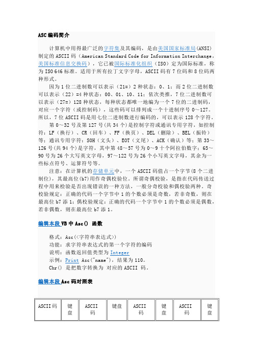
ASC编码简介
键盘
27
ESC
32
SPACE
33
!
34
"
35
#
36
$
37
%
38
&
39
'
40
(
41
)
42
*
43
+
44
'
45
-
46
.
47
/
48
0
49
1
50
2
51
3
52
4
53
5
54
6
55
7
56
8
57
9
58
:
59
;
60
<
61
=
62
>
63
?
64
@
65
A
66
B
67
C
68
D
69
E
70
F
71
G
72
H
73
I
74
J
75
K
76
编辑本段VB中Asc()函数
格式:Asc(<字符串表达式>)
功能:求字符串表达式的第一个字符的编码
说明:函数返回值类型为Integer
示例:PrintAsc("name"),结果为110。
Chr()是把数字转换为对应的ASCII码。
编辑本段Asc码对照表
ASCII码
键盘
ASCII码
键盘
ASCII码
键盘
因为1位二进制数可以表示(21=)2种状态:0、1;而2位二进制数可以表示(22)=4种状态:00、01、10、11;依次类推,7位二进制数可以表示(27=)128种状态,每种状态都唯一地编为一个7位的二进制码,对应一个字符(或控制码),这些码可以排列成一个十进制序号0~127。所以,7位ASCII码是用七位二进制数进行编码的,可以表示128个字符。
关于ACS800变频器拷贝参数

镇江明润信息科技有限公司内部技术文件
关于 ACS800 变频器自动控制
2
3
4
进入包含上传、 下载 和调节亮度功能的 页面。
5
选择下载功能 ( 闪 烁光标显示了所选 功能项)。
6
执行下载功能。
5/5
拷贝参数的几点说明(V1.0)
2016 年 3 月 18 日 华文博
1/5
镇江明润信息科技有限公司内部技术文件
目
录
面板拷贝参数的简介 ............................................................................................................... 3 拷贝参数的实现方法 ............................................................................................................... 4 上载参数 ......................................................................................................................... 4 下载参数 ......................................................................................................................... 5
- 1、下载文档前请自行甄别文档内容的完整性,平台不提供额外的编辑、内容补充、找答案等附加服务。
- 2、"仅部分预览"的文档,不可在线预览部分如存在完整性等问题,可反馈申请退款(可完整预览的文档不适用该条件!)。
- 3、如文档侵犯您的权益,请联系客服反馈,我们会尽快为您处理(人工客服工作时间:9:00-18:30)。
A CS800 电压及功率范围电机[kW]280019001450800200110375.51.51.10.55200240380415500690[V]电源电压ACS 800用于控制1.1至500kW交流电机广泛的应用场合ACS800系列传动产品最大的优点就是在全功率范围内统一使用了相同的控制技术,例如启动向导,自定义编程,DTC 控制,通用备件,通用的接口技术,以及用于选型、调试和维护的通用软件工具。
先进技术 - D T CACS800的核心技术就是直接转矩控制(DTC)。
它是目前最先进的交流异步电机的控制方式。
DTC稳定杰出的性能,使ACS800传动产品适用于各种工业领域。
启动向导ABB交流传动持续不断的在完善用户界面。
启动向导的应用,使ACS800的调试变得非常简便。
自定义编程与传统的参数编程相比,ACS800的自定义编程,具有更好的适应性。
作为全系列的标准配置,就象传动产品内置了小型的PLC,且不需要添加任何附加的软硬件。
高度集成和紧凑的结构设计作为标准配置,ACS800全系列已经内置了电抗器。
此外,在它的内部还可以同时再安装三个可选模块:I/O扩展模块,现场总线适配器模块,脉冲编码器接口模块或PC机的接口模块。
增加了这些模块并不增加体积,也无须用导线连接。
环保产品ABB是ICC ( 国际商会 ) 可持续发展商务的成员,并一直致力于环境的保护。
ABB 交流传动产品遵循16项ICC的规定,在生产过程中遵循ISO14001标准。
A C S 800 技术数据3-:相供电电压U3IN = 380...415 V + 10%U5IN = 380...500 V + 10%:频率48...63 Hz:功率因数cosϕ1=0.98 ()基波c o sϕ=0.93...0.95 ()总体:额定功率时ACS800-0X> 98%ACS800-17> 97%3-:相输出电压0...U3I N/U5I N:频率控制0...+ 300Hz0...+120Hz (du/dt)带滤波器时:弱磁点8...300 Hz:电机控制软件(DTC)直接转矩控制:转矩控制:转矩阶跃响应时间开环<5 ms 额定转矩阶跃响应时间闭环<5 ms 额定转矩阶跃响应时间:非线性度(额定转矩时)开环+4%闭环+1%:速度控制静态精度(额定转矩阶跃响应时):开环10%电机滑差的闭环0.01%额定转速的:动态精度开环0.3...0.4%秒闭环0.1...0.2%秒:环境温度:运输-40 (70):储存-40 (70):运行-15 (50)40...50C (1%/1C)时输出功率降容ACS800-17 40...50C (1.5%/1C)时输出功率降容相对湿度595%,至没有冷凝。
:冷却方式空气冷却:海拔高度0...1000 m 不需要降容1000...4000 m (690V1000...需要降容单元2000m降容)ACS800-01 壁挂式单传动1.1 至 110 kWACS800-02 立柜式单传动90 至 500 kW紧凑完整型单传动ACS800-01和-02单传动的防护等级分为IP21,或IP54,IP55(仅适用于ACS800-01)。
ACS800-01使用的电机的功率从1.1kW到110kW,ACS800-02使用的电机的功率从90kW到500kW,ACS800-02有一个全新书架式机壳。
ACS800-01和ACS800-02只是在机械结构上有所不同。
方便的安装ACS800-02具有独一无二的紧凑型书架设计。
书架式设计,允许传动并排安装。
用户可以根据自身的要求,对传动的位置和距离进行协调。
紧凑型的结构设计从最小型号的ACS800-01到最大型号的ACS800-02,其内部都配有扩展选项。
包括抑制谐波的电抗器、传动保护设备、 I/O扩展、具有启动向导的用户控制盘和低噪音冷却风扇功能。
此外,模块内部还预留了一定的空间,供用户使用:即如果用户需要的I/O口超出了标准配置数量,也不必将扩展模块置于传动之外。
因为在传动模块内部预留有三个专为放置可选模块的插槽 。
这三个位置也可以为其它附件使用。
ACS800-02可以通过增加附加柜体来实现更多的附加件的选择及安装。
标准硬件特征:• IP 21 防护等级• 紧凑型设计• 内置谐波电抗器• 长寿命设计的风扇和 电容• 可扩展编程I/O 口• 输入端隔离• 内置I/O扩展和现场总 线通讯模块插槽• 配有启动向导的多语 言控制盘• 大功率端子,允许使 用铝质电缆ACS800-02:• 自由固定方式• 两种标准安装方向• 宽度优化的书架式 设计H 1=壳体高度(带电缆连接盒)H 2=壳体高度(无电缆连接盒)W1=标准壳体的宽度W 2=柜体宽度(安装扩展外壳)N/A =无效A)书架式安装的尺寸。
平板式安装的宽度和深度会有所改变。
B)安装扩展外壳时,由于熔断开关手柄的影响,深度会增加25m m 。
C)没有电缆连接盒的A C S 800-01不满足I P 21防护等级要求。
:防护等级IP21(标准)IP55(对ACS800-01为可选)柜体颜色:NCS1502-Y(RAL90021/PMS420S)机壳*)基本配置的重量,含熔断开关,不含接触器和其它选件。
Ic o n t.m a x:40摄氏度不过载情况下的额定电流。
IMAX:最大输出电流。
启动时可以连续提供电流10秒钟,其它情况下,时间的长度取决于传动的温度。
注意:最大电机轴功率是150%Phd。
典型值(Typical Rating)无过载应用(No-overload use)Pc o n t.m a x: 无过载应用的典型电机功率。
轻度过载应用(Light-overload use)IN:连续额定电流,在温度40摄氏度时,允许过载1分钟,过载电流为110%IN。
PN:轻度过载应用的典型电机功率。
重载应用(Heavy-duty use)Ihd:连续额定电流,在温度40摄氏度时,允许过载1分钟,过载电流为150%IN。
Phd:重载应用的典型电机功率。
对于同一个电压等级,不管供电电压如何,电流的额定值总是相同的。
额定值是用于环境温度为40摄氏度。
温度高于40度时(最大为50 C),需要降容处理(1%/1 C)注意:1)如果Tamb < 25摄氏度,允许50%过载。
如果Tamb = 40摄氏度,1分钟的最大过载量为37%。
2)如果Tamb < 30摄氏度,允许50%过载。
如果Tamb = 40摄氏度,1分钟的最大过载量为40%。
3)如果Tamb < 20摄氏度,允许50%过载。
如果Tamb = 40摄氏度,1分钟的最大过载量为30%。
4)如果输出频率大于41Hz,那么选择较大的值。
113ABD 00009726 REV E CN 26.12.2003ACS 800 单传动模块ACS800-04, 560 kW至优化的结构ACS800-04具有的许多优点使其成为嵌入式设计的最佳选择。
无需增加EMC 柜体。
ACS800-04传动内嵌了EMC 滤波器,因此无需任何附加的硬件就可以将辐射限制在EN 61800-3 标准之内。
结构上的集成,螺钉数量的减少,方便了传动模块附件的安装。
由于使DIN 用了导轨和新的安装平台,所以控制单元和控制面板的固定安装非常容易。
每台传动都配有详细的柜体安装指导,安装指导包括柜体的布局图,空气流量的要求和其它必要的信息。
具有大量内置可选件的紧凑型设计,使安装空间和安装工时降到最低。
方便的布线A CS800-04由于的功率电缆连接端有很大的空间,因此使功率电缆的连接非常方便。
而且单独分开的控制单元使I/O 得对口的连接也很方便。
控制单元可以安装在柜体内,这样无需打开传动模块的外壳就I/O 可以对口进行操作。
由于进线电缆在模块顶部,这就很大程度地减少了柜体内部的母排和电缆的用量,优化了布线。
灵活的安装ACS800-04的模块化安装提供了多种安装方式用于满足用户的多种需求。
例如:壁挂式或落地式,以及左右互换出线式。
Icont.max:40摄氏度不过载情况下的额定电流。
IMAX:最大输出电流。
启动时可以连续提供电流10秒钟,其它情况下,时间的长度取决于传动的温度。
注意:最大电机轴功率是150%Phd。
典型值(Typical Rating)无过载应用(No-overload use)Pcont.max: 无过载应用的典型电机功率。
轻度过载应用(Light-overload use)IN:连续额定电流,在温度40摄氏度时,允许过载1分钟,过载电流为110%IN。
PN:轻度过载应用的典型电机功率。
重载应用(Heavy-duty use)Ihd:连续额定电流,在温度40摄氏度时,允许过载1分钟,过载电流为150%IN。
Phd:重载应用的典型电机功率。
对于同一个电压等级,不管供电电压如何,电流的额定值总是相同的。
额定值是用于环境温度为40摄氏度。
温度高于40度时(最大为50 C),需要降容处理(1%/1 C)注意:1)如果Tamb < 25摄氏度,允许50%过载。
如果Tamb = 40摄氏度,1分钟的最大过载量为37%。
2)如果Tamb < 30摄氏度,允许50%过载。
如果Tamb = 40摄氏度,1分钟的最大过载量为40%。
3)如果Tamb < 20摄氏度,允许50%过载。
如果Tamb = 40摄氏度,1分钟的最大过载量为30%。
4)如果输出频率大于41Hz,那么选择较大的值。
配备输出侧电缆连接板的宽度*)与每个传动单元配套书架式设计平板式设计防护等级:IP 00颜色:NCS 1502-Y (RAL 90021/PMS 420C)机壳123ABD 00009726 REV E CN 26.12.2003133ABD 00009726 REV E CN 26.12.2003ACS800柜体式单传动ACS800-07, 2800 kW至灵活的解决方案ACS800-07是专为工业场合设计的柜体式单传动。
它具有结构紧凑、功率范 2800 kW 围广的特点, 3.2传动的宽度仅为IP 21,米。
并且可以提供IP 22, IP 42, IP 54 几种防护等级。
ACS800-07提供了多种标准配置以适应各种不同的应用场合,从进线接触器到电机防误启动保护ATEX 器。
ABB 可以通过在标准产品上加装附加件来确保满足客户的应用要求。
灵活模块的概念500 kW 在以下的传动是紧凑的单传动模块,模块包括整流单元和逆变单元。
大型的传动包括单独的整流单元和逆变单元,提供了独立的电源接口,以方便维护。
并且可以通过并联的方式达到冗余的要求。
整流单元提供6 12标准的或脉波整流。
