PL34220191000BJBC中文资料
从施耐德产品标签识别订货号、序列号、生产批次号

施耐德产品标签信息识别施耐德电气售后服务部2014年4月目录前言 (3)PLC系列 (4)昆腾Quantum——140* (4)Micro——TSX* (4)Premium——TSX* (5)M340——BMX* (5)Mmentum——170* (6)Advantys——STB* (6)Twdio——TWD* (7)M258——TM258* (7)M238——TM238* (8)M218、M208——TM218*、TM208* (8)Zelio——SR2*、SR3* (9)触摸屏系列 (9)XBTGT*、XBTGK*、XBTOT*、MPC*、HMIGTO* (9)HMIGXO* (10)HMISTU* (10)XBTN* (10)变频器、软启动器系列 (11)变频器——ATV* (11)软启动器——ATS* (11)伺服驱动和电机系列 (12)伺服——LXM23* (12)伺服——LXM32* (12)电机——BCH* (13)电机——BSH*、BMH* (13)配电产品系列 (14)EasyPact——LV* (14)微型断路器 (15)电动操作机构 (15)工业控制系列 (16)接触器——LC1D* (16)热继电器 (17)马达保护器——GV2* (18)开关电源 (19)前言在维修换货以及技术咨询过程中,我们需要用户提供订货号、序列号、生产批次号等信息。
这些信息大多数都能够从产品标签上获得。
本文档旨在指导用户轻松识别施耐德标签上这些信息。
订货号是比产品型号更加具体的代号,他不仅包括型号信息,还可能包括产品的版本、产地等信息。
申请维修退返以及下订单都必须要有订货号。
在产品标签上,订货号一般以加粗、相对较大的字体标出,可能为一串字符,也有可能是分开的几串字符的组合。
序列号为产品的唯一性编号,一般为“SN”标识的一串字母、数字组合,并且辅以条形码或者二维码,以便出入库扫描。
生产批次号标示了产品生产日期,分为年周标记和年月日标记两种计法。
芯片手册
功能简述 ............................................................................ 26 编程指南 ............................................................................ 26 载波通信的工作步骤 .................................................................. 27 寄存器 .............................................................................. 28
9) ISO7816 功能 ........................................................... 41
功能简述 ............................................................................ 41 编程指南 ............................................................................ 41 寄存器 .............................................................................. 42
4) LCD/LED显示驱动 ........................................................ 32
C1419中文资料
Vectron International · v.2005-02-10 · page 1 of 3Vectron International Headquarters Vectron International LLC. 100 Watts StreetVectron international GmbH & Co. KG LandstrasseVectron Asia Pacific Sales OfficeUnit 3119 31st Floor, Jin Mao Tower, 88Typical ApplicationsFeaturesTelecommunication Standard 4-Pin DIP Package Universal Clock Enable FunctionPrevious Vectron Model NumbersMCO1XXX; AA;Frequency range1 MHz – 100 MHzFrequency stabilities 1ParameterMin Typ Max. Units Operating temprange Ordering Code 5Overall (vs. Initial, vs. operatingtemperature range vs. supply voltage change vs. load change vs. aging /1. Yea)r-100.0 -50.0 -25.0 -100.0 -50.0 -32.0+100.0 +50.0 +25.0 +100.0 +50.0 +32.0ppm ppm ppm ppm ppm ppm-0 … +70°C -0 … +70°C -0 … +70°C -40 … +85°C -40 … +85°C -40 … +85°CC104 C505 C255 F104 F505 F325Supply voltageParameterMin Typ Max. Units ConditionOrdering Code 5Supply voltage (Vs)4.755.0 5.25 VDCSV050Current consumption40 50 55 70 mA@ HCMOS fo < 24.0 MHz @ HCMOS fo < 50.0 MHz @ HCMOS fo < 70.0 MHz @ HCMOS fo < 100.0 MHz Supply voltage (Vs) 3.135 3.3 3.465 VDC SV033 Current consumption30 35 40 50mA@ HCMOS fo < 24.0 MHz @ HCMOS fo < 50.0 MHz @ HCMOS fo < 70.0 MHz @ HCMOS fo < 100.0 MHzRF outputParameter Min Typ Max.Units ConditionOrdering Code 5SignalHCMOSRFHLoad15.0 pFRise and Fall time 10 ns @ 15 pF 10 to 90 %Duty cycle4060%@ Vs/2Vectron International · v.2005-02-10 · page 2 of 3Vectron International Headquarters Vectron International LLC.100 Watts StreetVectron international GmbH & Co. KGLandstrasseVectron Asia Pacific Sales OfficeUnit 3119 31st Floor, Jin Mao Tower, 88EnclosuresAbsolute Maximum RatingsParameter Min Typ Max. Units Condition Supply voltage (Vs) 7 VOperable temperature range -30 +80 °CStorage temperature range -40 +90 °CVectron International · v.2005-02-10 · page 3 of 3Vectron International Headquarters Vectron International LLC.100 Watts StreetVectron international GmbH & Co. KGLandstrasseVectron Asia Pacific Sales OfficeUnit 3119 31st Floor, Jin Mao Tower, 88How to Order this Product:Step 1 Use this worksheet to forward the following information to your factory representative:Model Stability Code Supply Voltage Code RF Output Code Package Code C1419Example: C1419 C104 SV050 RFH A1Step 2 The factory representative will then respond with a Vectron Model Number in the following Configuration: Model Package Code Dash Dash NumberC1419 [Customer Specified Package Code]- [Factory Generated 4 digit number] Typical P/N = C1419A1-0001Notes:1 Contact factory for improved stabilities or additional product options. Not all options and codes are available at all frequencies.2 Unless otherwise stated all values are valid after warm-up time and refer to typical conditions for supply voltage, frequency controlvoltage, load, temperature (25°C)3 Phase noise degrades with increasing output frequency.4 Subject to technical modification.5 Contact factory for availability.。
ADP3421笔记本电脑CPU供电芯片引脚功能

ADP3421是笔记本电脑主板上常用的电源管理芯片,如IBM的T20,T21,T22,A系列笔记本电源控制芯片均采用ADP3421,该芯片通常与ADP3410搭配使用. [1]~o/e0笔记本电脑中的ADP3421芯片很容易损坏,通常表现为莫命其妙地死机,开机后不定期掉电或开机时根本无法加电等现像. (BfyHuL9' M1VHYS核心电压滞后比例设置端 ;Q8[1]rAsf 92CLSET电流限制设置端 _i&awm/ U3LTO标准译码输出端,该脚电压不能低于1.5VD)LqkfJ}z^4LTI标准译码输入端 aSNTm8SY X5LTB标准译码电路偏置电压输入端 Kd,7x'h`E6VID4 `Df)wNN17VID3 !Zf)N_k8VID2CPU电压模式识别端 7b[vZNi_9VID1 s@bo df&10VID0 )0Lv-?Gs[1]11CLKDRV2.5V线性稳压电源驱动信号输出端 E%C 02sI12CLKFB2.5V线性稳定电源反馈端 \ lpR+zaF13IODRV1.5V线性稳压电源驱动信号输出端 8MPXrc,9-14IOFB1.5V线性稳压电源反馈端 0/Ju sQ15SD待机控制端,该脚为低电平时电路停止工作 B?J#NFUb16PWRGDPOWERGOOD监视信号输出端 m4 8m 5>17UVLO欠压检测端 %t^-G?uz18SSL线性稳压器软启动控制端 `!\`yI$!%w19SSC核心电压软启动控制端 f#UT~/~bL220CORE核心电压镜像检测输出端 m[FH >21DACOUTDAC数字信号输出端 RcH",*U22GND地 7Z/KXc[b23OUT核心电压驱动信号输出端 { ?' DZR s24VCC供电端 C. H r25RAMP电流斜率输入端,该端是核心输出电压的反相反馈输入端 0x\b[1]DWZ_26REG基准电压输出端 iIoeG_^*Y27CS+电流限制正相检测输入端 C-a bc +/28CS-电流限制反相检测输入端 b*xw=G3%ADP3421损坏 IBM A21M不工作机器型号:IBM A21M故障现象:按下开机键,电源指示灯闪一下即灭,机器不工作。
29400资料
PRELIMINARY
(February, 2001, Version 0.1)
1
AMIC Technology, Inc.
元器件交易Hale Waihona Puke
A29400 Series
The host system can detect whether a program or erase operation is complete by reading the I/O7 ( Data Polling) and I/O6 (toggle) status bits. After a program or erase cycle has been completed, the device is ready to read array data or accept another command. The sector erase architecture allows memory sectors to be erased and reprogrammed without affecting the data contents of other sectors. The A29400 is fully erased when shipped from the factory. The hardware sector protection feature disables operations for both program and erase in any combination of the sectors of memory. This can be achieved via programming equipment. The Erase Suspend feature enables the user to put erase on hold for any period of time to read data from, or program data to, any other sector that is not selected for erasure. True background erase can thus be achieved. Power consumption is greatly reduced when the device is placed in the standby mode. The hardware RESET pin terminates any operation in progress and resets the internal state machine to reading array data.
惠普(HP)打印机技术规格与支持的纸种说明书

Pregledajte tehničke specifikacije i podržane vrste papira za štampač.●Tehničke specifikacije●Podržani tipovi papiraTehničke specifikacijePregledajte tehničke specifikacije za štampač.Za najnovije informacije posetite /support/ljM329MFP, /support/ljM428MFP, ili /support/ljM429MFP.Tabela 1 Tehničke specifikacije po modelu štampačaIme modela Broj proizvoda Ime modela Broj proizvoda Ime modela Broj proizvoda M428fdwW1A30AM429fdwW1A35AM428dwW1A28AM428dwW1A31AM429dwW1A33AM428fdnW1A29AM428fdnW1A32AM429fdnW1A34AM329dnW1A23AM329dwW1A24ARad sa papirom Ležište 1 (kapacitet 100 listova)Priloženo Priloženo Priloženo Priloženo Priloženo Rad sa papirom Ležište 2 (kapacitet 250 listova)Priloženo Priloženo Priloženo Priloženo Priloženo Rad sa papirom Opciono pomoćno ležište za 550listova Opcionalno Opcionalno Opcionalno Opcionalno Opcionalno Rad sa papirom Automatsko dupleks štampanje Priloženo Priloženo Priloženo Priloženo Priloženo Povezanost10/100/1000 Ethernet LAN vezasa IPv4 i IPv6 protokolima Priloženo Priloženo Priloženo Priloženo Priloženo Povezanost Hi-Speed USB 2.0Priloženo Priloženo Priloženo Priloženo Priloženo Povezanost Port za USB usputno štampanje Priloženo Priloženo Priloženo Priloženo Priloženo Povezanost Server za štampanje zapovezivanje na bežičnu mrežu Priloženo Priloženo Nije dostupno Nije dostupno Priloženo Povezanost Bluetooth Low Energy (BLE)Priloženo Priloženo Nije dostupno Nije dostupno Priloženo Povezanost Wi-Fi Direct za štampanje samobilnih uređaja Priloženo Priloženo Nije dostupno Nije dostupno PriloženoEkran i ulazni interfejs kontrolne table Kontrolna tabla sa ekranom u bojiosetljivim na dodir Priloženo Priloženo Priloženo Priloženo PriloženoSRWW1Tabela 1 Tehničke specifikacije po modelu štampača (nastavljeno)Ime modela Broj proizvoda Ime modela Broj proizvoda Ime modela Broj proizvoda M428fdw W1A30A M429fdw W1A35AM428dw W1A28A M428dw W1A31A M429dw W1A33A M428fdn W1A29A M428fdn W1A32A M429fdn W1A34A M329dn W1A23AM329dw W1A24AŠtampanjeŠtampa 38 stranica u minutu (ppm) na papiru veličine A4 i 40 stranica na papiru Letter formata Priloženo PriloženoPriloženoNije dostupnoNije dostupnoŠtampanjeŠtampa 35 stranica u minutu (ppm) na papiru veličine A4 i 37stranica na papiru Letter formata Nije dostupno Nije dostupno Nije dostupno Priloženo PriloženoŠtampanje Skladištenje zadataka i privatno štampanje Priloženo Priloženo Priloženo Priloženo Priloženo FaksFunkcije faksaPriloženo Nije dostupno Priloženo Nije dostupno Nije dostupno Kopiranje i skeniranje Kopira i skenira do 32 stranica u minutu (ppm)PriloženoPriloženoPriloženoPriloženoPriloženoKopiranje i skeniranjeDvoglavi ulagač dokumenata za 50 stranica sa automatskim dvostranim kopiranjem i skeniranjemPriloženo Nije dostupno Priloženo Nije dostupno Nije dostupnoKopiranje i skeniranjeUlagač dokumenata za 50 stranica sa jednostranim kopiranjem i skeniranjem Priloženo Priloženo Priloženo Priloženo PriloženoKopiranje i skeniranjeOpcije Skeniranja u e-poštu, Skeniranja na USB i Skeniranja u mrežnu fascikluPriloženo Priloženo Priloženo Priloženo PriloženoPodržani tipovi papiraUlazna ležišta i jedinica za dvostrano štampanje podržavaju nekoliko vrsta papira. Ležište 1 podržava papir u opsegu težine od 60 do 175 g/m 2. Ležište 2, ležište 3 (opcionalno) i jedinica za dvostrano štampanje podržavaju papir u opsegu težine od 60 do 120 g/m 2.NAPOMENA:Kako biste postigli najbolje rezultate, pre štampanja u upravljačkom programu štampača izaberite ispravan format i vrstu papira.2SRWWTabela 2 Tipovi papira koje podržavaju ulazna ležišta i jedinica za dvostrano štampanjeVrsta papira Tray 1 (Ležište3)Tray 2 (Ležište3)Ležište 3(opcionoležište za 550listova)Jedinica zadvostranoštampanje(modeli saautomatskomjedinicom zadvostranoštampanje)RučnodvostranoštampanjeRavno Podržano Podržano Podržano Podržano PodržanoHP EcoEfficient Podržano Podržano Podržano Podržano PodržanoLak 60-74 g Podržano Podržano Podržano Podržano PodržanoSrednji 85-95 g Podržano Podržano Podržano Podržano PodržanoSrednje težak 96–110 g Podržano Podržano Podržano Podržano PodržanoTežak 111–130 g Podržano Podržano Podržano Nije podržano PodržanoIzuzetno težak 131–175 g Podržano Nije podržano Nije podržano Nije podržano PodržanoOznake Podržano Nije podržano Nije podržano Nije podržano Nije podržanoMemorandum Podržano Podržano Podržano Podržano PodržanoKoverte Podržano Nije podržano Nije podržano Nije podržano Nije podržanoPrethodno štampano Podržano Podržano Podržano Podržano PodržanoPerforirano Podržano Podržano Podržano Podržano PodržanoU boji Podržano Podržano Podržano Podržano PodržanoČvrst papir Podržano Podržano Podržano Podržano PodržanoReciklirano Podržano Podržano Podržano Podržano PodržanoHrapavo Podržano Podržano Podržano Nije podržano Podržano SRWW Podržani tipovi papira34SRWW。
佳能(CANON)打印机耗材对照表

黑色墨盒
(带头)
BJ30/BJ70/BJC50/BJC55
BCI-10B
黑
BC-10头专用
BCI-11E
彩色墨盒
(带头)
BJC80/BJC85/BJC85PW/BJC50/BJC55
BCI-11B
黑
BC-11E头专用
BCI-11C
彩
BC-12E
彩色照片墨盒
BJC-85/BJC-55
BX-2
/MPC600/MPC400/MPC730/I865/MPC700
BCI-3EPM
浅红
BCI-3EPBK
浅黑色
BCI-6EBK
黑
S800/S900/i9100/i950/830D/i905D/I9950/I990/I865/I560/IP8500
/IP6000D/IP4000/IP5000/MP780
PG50BK
黑色墨盒
CL8BK
黑
MP500/MP530/MP600/MP610/MP810/MP830/IP4000/IP4200
/IP4300/IP4500/IP5300/PRO9000/MX850
CLI-8C/M/Y
黄/品红/青分离色
MP500/MP510/MP530/MP600/810/830/MP520/610/MX700/IP3300
BCI-6EC
兰
S800/S900/i9100/i950/830D/i905D/I9950/I990/I865/I560/IP8500
/IP6000D/IP4000/IP5000/MP780/IP300
BCI-6EM
红色
BCI-6EY
黄色
BCI-6EPC
佳能系列喷墨打印机打印头维护常识

佳能系列喷墨打印机打印头维护常识佳能系列喷墨打印机具有操作简单、打印文字图像清晰、价格相对低廉的优点纸品包装,在国内使用比较广泛,而在喷墨打印机的使用当中,墨盒和打印头是我们维护的重点。
佳能系列喷墨打印机的墨盒分为一体和分体两种方式。
一体式墨盒以BC01/02、BC05/06为代表,墨水盒与打印头为一整体当墨水使完后,打印头也随之丢弃,导致打印成本提高,且造成了资源浪费和环境污染。
因此填充墨水这一概念应运而生,在全球许多国家得到普遍推广。
BJ-10ex墨盒主要由墨盒体及其中的墨水海棉、喷头单元、侧盖顶盖等组成,其中的网状墨水过滤器用来滤除墨水中的杂质、气泡和灰尘晒版,墨盒体上的导气孔的作用则是导入空气,使盒内压力取得平衡。
分体式墨盒以BCI21、BJ330、BJC800打印机的墨盒为代表。
墨水盒与打印头分离,墨水使完后可换一个,打印头可继续使用,显然其打印成本要低很多印刷适性,而且用户可以选择价格更低的优质兼容墨盒。
该类墨盒可以BJC4000打印机的BCI21黑色墨盒和BJ300/330打印机的BJI642墨盒为例,前者的优点在于供墨口的涤纶纤维芯。
该芯是由特殊纤维制成的,比墨盒内的海棉更细密、更均匀,因此它可以比较有效地起到过滤和传导作用,特别是过滤掉墨水中残留的空气气泡。
我们认为绦沦纤维芯的设计使佳能原装及其代用墨盒能够成功地避免许多使用方面的问题。
即使如此过度包装,用户也应该严格按照打印机使用手册的有关规定,保养和使用打印机及其墨盒。
同时由于墨水具有导电性,应防止将其溅到打印机的印刷电路板上,以免出现短路现象。
如果印刷电路板上已有墨水沾污,应用含酒精的纸巾擦拭。
而在使用过程中出现的所谓打印头烧坏现象软件,大部分是由于墨水漏到印刷电路板上而造成的。
当然如果用户未执行一些规定的操作或者执行了错误操作,也会引发部分使用问题。
如未撕去喷嘴封条或墨盒供墨口的封口膜,以致打印不出,或撕去封口膜后未及时将墨盒装入机器,而长时间暴露在空气中EFI,使海棉干结(如果发生这种情况,墨盒就基本失效了)。
硒鼓通用型号对照表(1)

HP 278
Canon 328/326
完全通用
HP 285
Canon 325/925
完全通用
HP 505
Canon 319
完全通用
HP 6511
Canon 310
完全通用
HP 2600(6000---6003)
Canon 5000/5100/307
完全通用,进口芯片
HP 1215(540---543)
通用、芯片不同
三星1053S
施乐3140/3155/3160
东芝220S/221S
戴尔1130/1133/1135
通用、芯片不同
三星2850/209S
施乐3220
通用、芯片不同
三星3050/5530
施乐3428/3435
戴尔1815
完全通用
?
利盟230
戴尔1700
通用、芯片不同
三星1043S
联想1680
施乐210
新件通用、芯片不同
联想0112/0225粉盒
兄弟6600粉盒
通用
联想0225硒鼓
兄弟6600硒鼓
完全通用
联想2020粉盒
兄弟2050粉盒
施乐203
完全通用
联想2020硒鼓
兄弟2050硒鼓
施乐203
完全通用
联想2822/2922粉盒
兄弟2115粉盒
完全通用
联想2822/2922硒鼓
兄弟2150硒鼓
利盟250粉盒
戴尔1720
联想3900粉盒
新件通用、芯片不同
利盟250硒鼓
戴尔1721
新件完全通用
利盟230粉盒
戴尔1700/1710
LMV342中文资料

LMV341/LMV342/LMV344Single with Shutdown/Dual/Quad General Purpose,2.7V,Rail-to-Rail Output,125˚C,Operational AmplifiersGeneral DescriptionThe LMV341/342/344are single,dual,and quad low volt-age,and low power Operational Amplifiers.They are de-signed specifically for low voltage portable applications.Other important product characteristics are low input biascurrent,rail-to-rail output,and wide temperature range.The patented class AB turnaround stage significantly re-duces the noise at higher frequencies,power consumption,and offset voltage.The PMOS input stage provides the userwith ultra-low input bias current of20fA(typical)and highinput impedance.The industrial-plus temperature range of-40˚C to125˚Callows the LMV341/342/344to accommodate a broad rangeof extended environment applications.LMV341expands Na-tional Semiconductor’s Silicon Dust™amplifier portfolio of-fering enhancements in size,speed,and power savings.TheLMV341/342/344are guaranteed to operate over the voltagerange of2.7V to5.0V and all have rail-to-rail output.The LMV341offers a shutdown pin that can be used todisable the device.Once in shutdown mode,the supplycurrent is reduced to45pA(typical).The LMV341/342/344have29nV Voltage Noise at10KHz,1MHz GBW,1.0V/µsSlew Rate,0.25mVos,and0.1µA shutdown current(LMV341.)The LMV341is offered in the tiny SC70-6L package,theLMV342in space saving MSOP-8and SOIC-8,and theLMV344in TSSOP-14and SOIC-14.These small packageamplifiers offer an ideal solution for applications requiringminimum PC board footprint.Applications with area con-strained PC board requirements include portable electronicssuch as cellular handsets and PDAs.Features(Typical2.7V Supply Values;Unless Otherwise Noted)n Guaranteed2.7V and5V specificationsn Input referred voltage noise(@10kHz)29nV/n Supply current(per amplifier)100µAn Gain bandwidth product 1.0MHzn Slew rate 1.0V/µsn Shutdown Current(LMV341)45pAn Turn-on time from shutdown(LMV341)5µsn Input bias current20fAApplicationsn Cordless/cellular phonesn Laptopsn PDAsn PCMCIA/Audion Portable/battery-powered electronic equipmentn Supply current monitoringn Battery monitoringn Buffern Filtern DriverConnection DiagramSC70-6L20030441Top ViewOrder NumberLMV341MG,LMV341MGXLMV342MM,LMV342MMXLMV342MA,LMV342MAXLMV344MT,LMV344MTXLMV344MA,LMV344MAXSample and Hold Circuit20030444March2003LMV341/LMV342/LMV344SinglewithShutdown/Dual/QuadGeneralPurpose,2.7V,Rail-to-RailOutput,125˚C,OperationalAmplifiers ©2003National Semiconductor Corporation Absolute Maximum Ratings(Note 1)If Military/Aerospace specified devices are required,please contact the National Semiconductor Sales Office/Distributors for availability and specifications.ESD Tolerance (Note 2)Machine Model 200V Human Body Model 2000VDifferential Input Voltage ±Supply VoltageSupply Voltage (V+-V −)5.5VOutput Short Circuit to V +(Note 3)Output Short Circuit to V−(Note 4)Storage Temperature Range −65˚C to 150˚CJunction Temperature (Note 5)150˚CMounting TemperatureInfrared or Convection Reflow (20sec.)235˚C Wave Soldering Lead Temp.(10sec.)260˚COperating Ratings (Note 1)Temperature Range −40˚C to 125˚CThermal Resistance (θJA )6-Pin SC70414˚C/W 8-Pin SOIC 190˚C/W 8-Pin MSOP 235˚C/W 14-Pin TSSOP 155˚C/W 14-Pin SOIC145˚C/W2.7V DC Electrical Characteristics(Note 10)Unless otherwise specified,all limits guaranteed for T J =25˚C,V +=2.7V,V −=0V,V CM =V +/2,V O =V +/2and R L >1M Ω.Boldface limits apply at the temperature extremes.Symbol ParameterConditionsMin (Note 7)Typ (Note 6)Max (Note 7)UnitsV OSInput Offset VoltageLMV3410.2544.5mVLMV342/LMV3440.5555.5TCV OS Input Offset Voltage Average Drift1.7µV/˚C I B Input Bias Current 0.02120250pA I OS Input Offset Current 6.6fA I SSupply CurrentPer Amplifier100170230µAShutdown Mode,V SD =0V (LMV341)45pA 1µA 1.5µACMRR Common Mode Rejection Ratio0V ≤V CM ≤1.7V 0V ≤V CM ≤1.6V 565080dB PSRR Power Supply Rejection Ratio 2.7V ≤V +≤5V 656082dB V CM Input Common Mode Voltage For CMRR ≥50dB 0−0.2to 1.9(Range)1.7VA VLarge Signal Voltage GainR L =10k Ωto 1.35V 7870113dBR L =2k Ωto 1.35V7264103V OOutput SwingR L =2k Ωto 1.35V246095mV609526R L =10k Ωto 1.35V5.030403040 5.3L M V 341/L M V 342/L M V 344 22.7V DC Electrical Characteristics(Note 10)(Continued)Unless otherwise specified,all limits guaranteed for T J =25˚C,V +=2.7V,V −=0V,V CM =V +/2,V O =V +/2and R L >1M Ω.Boldface limits apply at the temperature extremes.Symbol ParameterConditionsMin (Note 7)Typ (Note 6)Max (Note 7)UnitsI OOutput Short Circuit CurrentSourcingLMV341/LMV3422032mASourcing LMV3441824Sinking1524t on Turn-on Time from Shutdown (LMV341)5µs V SDShutdown Pin Voltage RangeON Mode (LMV341) 1.7to 2.7 2.4to 2.7V Shutdown Mode (LMV341)0to 10to 0.82.7V AC Electrical Characteristics(Note 10)Unless otherwise specified,all limits guaranteed for T J =25˚C,V +=2.7V,V −=0V,V CM =V +/2,V O =V +/2and R L >1M Ω.Boldface limits apply at the temperature extremes.Symbol ParameterConditionsMin (Note 7)Typ (Note 6)Max (Note 7)Units SR Slew RateR L =10k Ω,(Note 9) 1.0V/µs GBW Gain Bandwidth Product R L =100k Ω,C L =200pF 1.0MHz Φm Phase Margin R L =100k Ω72deg G m Gain MarginR L =100k Ω20dB e n Input-Referred Voltage Noise f =1kHz 40nV/i n Input-Referred Current Noise f =1kHz0.001pA/THDTotal Harmonic Distortionf =1kHz,A V =+1R L =600Ω,V IN =1V PP0.017%5V DC Electrical Characteristics(Note 10)Unless otherwise specified,all limits guaranteed for T J =25˚C,V +=5V,V −=0V,V CM =V +/2,V O =V +/2and R L>1M Ω.Boldface limits apply at the temperature extremes.Symbol ParameterConditionsMin (Note 7)Typ (Note 6)Max (Note 7)UnitsV OSInput Offset VoltageLMV3410.02544.5mVLMV342/LMV3440.7055.5TCV OS Input Offset Voltage Average Drift1.9µV/˚C I B Input Bias Current 0.02200375pA I OS Input Offset Current 6.6fA I SSupply CurrentPer Amplifier107200260µA Shutdown Mode,V SD =0V (LMV341)0.03311.5µA CMRR Common Mode Rejection Ratio0V ≤V CM ≤4.0V 0V ≤V CM ≤3.9V 565086dB PSRR Power Supply Rejection Ratio 2.7V ≤V +≤5V 656082dB V CMInput Common Mode VoltageFor CMRR ≥50dB0−0.2to 4.2(Range)4VLMV341/LMV342/LMV34435V DC Electrical Characteristics(Note 10)(Continued)Unless otherwise specified,all limits guaranteed for T J =25˚C,V +=5V,V −=0V,V CM =V +/2,V O =V +/2and R L>1M Ω.Boldface limits apply at the temperature extremes.Symbol ParameterConditionsMin (Note 7)Typ (Note 6)Max (Note 7)UnitsA VLarge Signal Voltage Gain (Note 8)R L =10k Ωto 2.5V 7870116dBR L =2k Ωto 2.5V7264107V OOutput SwingR L =2k Ωto 2.5V326095mV609534R L =10k Ωto 2.5V73040mV30407I O Output Short Circuit Current Sourcing 85113mA Sinking 5075t on Turn-on Time from Shutdown (LMV341)5µs V SDShutdown Pin Voltage RangeON Mode (LMV341) 3.1to 5 4.5to 5.0VShutdown Mode (LMV341)0to 10to 0.85V AC Electrical Characteristics(Note 10)Unless otherwise specified,all limits guaranteed for T J =25˚C,V +=5V,V −=0V,V CM =V +/2,V O =V +/2and R L>1M Ω.Boldface limits apply at the temperature extremes.Symbol ParameterConditionsMin (Note 7)Typ (Note 6)Max (Note 7)Units SR Slew RateR L =10k Ω,(Note 9) 1.0V/µs GBW Gain-Bandwidth Product R L =10k Ω,C L =200pF 1.0MHz Φm Phase Margin R L =100k Ω70deg G m Gain MarginR L =100k Ω20dB e n Input-Referred Voltage Noise f =1kHz 39nV/i n Input-Referred Current Noise f =1kHz0.001pA/THDTotal Harmonic Distortionf =1kHz,A V =+1R L =600Ω,V IN =1V PP0.012%Note 1:Absolute Maximum Ratings indicate limits beyond which damage to the device may occur.Operating Ratings indicate conditions for which the device is intended to be functional,but specific performance is not guaranteed.For guaranteed specifications and the test conditions,see the Electrical Characteristics.Note 2:Human body model,1.5k Ωin series with 100pF.Machine model,0Ωin series with 200pF.Note 3:Shorting output to V +will adversely affect reliability.Note 4:Shorting output to V -will adversely affect reliability.Note 5:The maximum power dissipation is a function of T J(MAX),θJA ,and T A .The maximum allowable power dissipation at any ambient temperature is P D =(T J(MAX)–T A )/θJA .All numbers apply for packages soldered directly into a PC board.Note 6:Typical values represent the most likely parametric norm.Note 7:All limits are guaranteed by testing or statistical analysis.Note 8:R L is connected to mid-supply.The output voltage is GND +0.2V ≤V O ≤V +−0.2VNote 9:Connected as voltage follower with 2V PP step input.Number specified is the slower of the positive and negative slew rates.Note 10:Electrical Table values apply only for factory testing conditions at the temperature indicated.Factory testing conditions result in very limited self-heating of the device such that T J =T A .No guarantee of parametric performance is indicated in the electrical tables under conditions of internal self heating where T J >T A .L M V 341/L M V 342/L M V 344 4Connection DiagramsSC70-6L8-Pin MSOP/SOIC14-Pin TSSOP/SOIC20030441 Top View20030451Top View20030452Top ViewOrdering InformationPackage Part Number Package Marking Transport Media NSC Drawing6-Pin SC70LMV341MGA781k Units Tape and ReelMAA06A LMV341MGX3k Units Tape and Reel8-Pin MSOPLMV342MMA82A1k Units Tape and ReelMUA08A LMV342MMX 3.5k Units Tape and Reel8-Pin SOICLMV342MALMV342MA95Units/RailM08A LMV342MAX 2.5k Units Tape and Reel14-Pin TSSOPLMV344MTLMV344MTRailsMTC14 LMV344MTX 2.5k Units Tape and Reel14-Pin SOICLMV344MALMV344MA55Units/RailM14ALMV344MAX 2.5k Units Tape and ReelLMV341/LMV342/LMV3445Typical Performance CharacteristicsSupply Current vs.Supply Voltage (LMV341)Input Current vs.Temperature2003042820030446Output Voltage Swing vs.Supply Voltage Output Voltage Swing vs.Supply Voltage2003042620030427I SOURCE vs.V OUT I SOURCE vs.V OUT2003042920030430L M V 341/L M V 342/L M V 344 6Typical Performance Characteristics(Continued)I SINK vs.V OUTI SINK vs.V OUT2003043120030432V OS vs.V CM V OS vs.V CM2003043320030434V IN vs.V OUT V IN vs.V OUT2003043520030436LMV341/LMV342/LMV3447Typical Performance Characteristics(Continued)CMRR vs.FrequencyPSRR vs.Frequency2003040320030401Input Voltage Noise vs.frequencySlew Rate vs.V SUPPLY2003040420030402Slew Rate vs.Temperature Slew Rate vs.Temperature2003042220030423L M V 341/L M V 342/L M V 344 8Typical Performance Characteristics(Continued)THD+N vs.FrequencyTHD+N vs.V OUT2003042520030424Open Loop Frequency Over Temperature Open Loop Frequency Response2003042120030420Open Loop Frequency ResponseGain &Phase vs.C L2003041920030417LMV341/LMV342/LMV3449Typical Performance Characteristics(Continued)Gain &Phase vs.C LStability vs.Capacitive Load2003041820030448Stability vs.Capacitive Load Non-Inverting Small Signal Pulse Response2003044920030405Non-Inverting Large Signal Pulse Response Non-Inverting Small Signal Pulse Response2003040820030406L M V 341/L M V 342/L M V 344 10Typical Performance Characteristics(Continued)Non-Inverting Large Signal Pulse ResponseNon-Inverting Small Signal Pulse Response2003040920030407Non-Inverting Large Signal Pulse Response Inverting Small Signal Pulse Response2003041020030411Inverting Large Signal Pulse Response Inverting Small Signal Pulse Response2003041420030412LMV341/LMV342/LMV34411Typical Performance Characteristics(Continued)Inverting Large Signal Pulse ResponseInverting Small Signal Pulse Response2003041520030413Inverting Large Signal Pulse Response Crosstalk Rejection vs.Frequency2003041620030454L M V 341/L M V 342/L M V 344 12Application SectionLMV341/342/344The LMV341/342/344family of amplifiers features low volt-age,low power,and rail-to-rail output operational amplifiers designed for low voltage portable applications.The family is designed using all CMOS technology.This results in an ultra low input bias current.The LMV341has a shutdown option, which can be used in portable devices to increase battery life.A simplified schematic of the LMV341/342/344family of amplifiers is shown in Figure1.The PMOS input differential pair allows the input to include ground.The output of this differential pair is connected to the Class AB turnaround stage.This Class AB turnaround has a lower quiescent current,compared to regular turnaround stages.This results in lower offset,noise,and power dissipation,while slew rate equals that of a conventional turnaround stage.The output of the Class AB turnaround stage provides gate voltage to the complementary common-source transistors at the output stage.These transistors enable the device to have rail-to-rail output.CLASS AB TURNAROUND STAGE AMPLIFIERThis patented folded cascode stage has a combined class AB amplifier stage,which replaces the conventional folded cascode stage.Therefore,the class AB folded cascode stage runs at a much lower quiescent current compared to conventional folded cascode stages.This results in signifi-cantly smaller offset and noise contributions.The reduced offset and noise contributions in turn reduce the offset volt-age level and the voltage noise level at the input of the LMV341/342/344.Also the lower quiescent current results in a high open-loop gain for the amplifier.The lower quiescent current does not affect the slew rate of the amplifier nor its ability to handle the total current swing coming from the input stage.The input voltage noise of the device at low frequencies, below1kHz,is slightly higher than devices with a BJT input stage;However the PMOS input stage results in a much lower input bias current and the input voltage noise drops at frequencies above1kHz.SAMPLE AND HOLD CIRCUITThe lower input bias current of the LMV341results in a very high input impedance.The output impedance when the de-vice is in shutdown mode is quite high.These high imped-ances,along with the ability of the shutdown pin to be derived from a separate power source,make LMV341a good choice for sample and hold circuits.The sample clock should be connected to the shutdown pin of the amplifier to rapidly turn the device on or off.Figure2shows the schematic of a simple sample and hold circuit.When the sample clock is high the first amplifier is in normal operation mode and the second amplifier acts as a buffer.The capacitor,which appears as a load on the first amplifier,will be charging at this time.The voltage across the capacitor is that of the non-inverting input of the first amplifier since it is connected as a voltage-follower.When the sample clock is low the first amplifier is shut off,bringing the output impedance to a high value.The high impedance of this output,along with the very high impedance on the input of the second amplifier,prevents the capacitor from discharg-ing.There is very little voltage droop while the first amplifier is in shutdown mode.The second amplifier,which is still in normal operation mode and is connected as a voltage fol-lower,also provides the voltage sampled on the capacitor at its output.SHUTDOWN FEATUREThe LMV341is capable of being turned off in order to conserve power and increase battery life in portable devices. Once in shutdown mode the supply current is drastically reduced,1µA maximum,and the output will be"tri-stated." The device will be disabled when the shutdown pin voltage is pulled low.The shutdown pin should never be left uncon-nected.Leaving the pin floating will result in an undefined operation mode and the device may oscillate between shut-down and active modes.The LMV341typically turns on2.8µs after the shutdown voltage is pulled high.The device turns off in less than400ns after shutdown voltage is pulled low.Figure3and Figure4 show the turn-on and turn-off time of the LMV341,respec-tively.In order to reduce the effect of the capacitance added to the circuit by the scope probe,in the turn-off time circuit a resistive load of600Ωis added.Figure5and Figure6show the test circuits used to obtain the two plots.20030453 FIGURE1.Simplified Schematic20030444FIGURE2.Sample and Hold CircuitLMV341/LMV342/LMV34413Application Section(Continued)LOW INPUT BIAS CURRENTThe LMV341/LMV342/LMV344Amplifiers have a PMOS in-put stage.As a result,they will have a much lower input bias current than devices with BJT input stages.This feature makes these devices ideal for sensor circuits.A typical curve of the input bias current of the LMV341is shown in Figure 7.20030440FIGURE 3.Turn-on Time20030439FIGURE 4.Turn-off Time20030442FIGURE 5.Turn-on Time20030443FIGURE 6.Turn-off Time20030447FIGURE 7.Input Bias Current vs.V CML M V 341/L M V 342/L M V 344 14Physical Dimensionsinches (millimeters)unless otherwise noted6-Pin SC70NS Package Number MAA06A8-Pin MSOPNS Package Number MUA08ALMV341/LMV342/LMV34415Physical Dimensionsinches (millimeters)unless otherwise noted (Continued)8-Pin SOICNS Package Number M08A14-Pin TSSOPNS Package Number MTC14L M V 341/L M V 342/L M V 344 16Physical Dimensionsinches (millimeters)unless otherwise noted (Continued)14-Pin SOICNS Package Number M14ALIFE SUPPORT POLICYNATIONAL’S PRODUCTS ARE NOT AUTHORIZED FOR USE AS CRITICAL COMPONENTS IN LIFE SUPPORT DEVICES OR SYSTEMS WITHOUT THE EXPRESS WRITTEN APPROVAL OF THE PRESIDENT AND GENERAL COUNSEL OF NATIONAL SEMICONDUCTOR CORPORATION.As used herein:1.Life support devices or systems are devices or systems which,(a)are intended for surgical implant into the body,or (b)support or sustain life,and whose failure to perform when properly used in accordance with instructions for use provided in the labeling,can be reasonably expected to result in a significant injury to the user.2.A critical component is any component of a life support device or system whose failure to perform can be reasonably expected to cause the failure of the life support device or system,or to affect its safety or effectiveness.National Semiconductor Americas Customer Support CenterEmail:new.feedback@ Tel:1-800-272-9959National SemiconductorEurope Customer Support CenterFax:+49(0)180-5308586Email:europe.support@Deutsch Tel:+49(0)6995086208English Tel:+44(0)8702402171Français Tel:+33(0)141918790National Semiconductor Asia Pacific Customer Support Center Fax:+65-62504466Email:ap.support@ Tel:+65-62544466National SemiconductorJapan Customer Support Center Fax:81-3-5639-7507Email:jpn.feedback@ Tel:81-3-5639-7560LMV341/LMV342/LMV344Single with Shutdown/Dual/Quad General Purpose,2.7V,Rail-to-Rail Output,125˚C,Operational AmplifiersNational does not assume any responsibility for use of any circuitry described,no circuit patent licenses are implied and National reserves the right at any time without notice to change said circuitry and specifications.。
342工业滑升门部分技术手册

A Company in the Cardo Group2005年5月阔福342工业滑升门工作原理:平衡系统(弹簧或配重)平衡门体的重量,通过外力(电机的扭力或手动拉力)来改变这个平衡,使门体在轨道内滑动。
平衡系统门板轨道A Company in the Cardo Group2005年5月阔福342工业滑升门各个部件名称:(注:因为门的安装及控制方式不同,有不同的部件,但主要部件名称都是相同的。
)请了解各个部件的名称,在与阔福沟通或参阅阔福资料的时候将会有极大的方便。
阔福342工业滑升门基本的技术参数:➢最小尺寸:2000X1500➢最大尺寸:8000X5500(弹簧平衡)*1➢表面材料:0.5mm厚的压花钢板铝板。
20微米厚的复合聚脂漆涂层,颜色可选➢门板厚度:42mm➢门板高度:500mm➢门板中间填充48kg/m3的无氟聚氨温发泡材料,含固定螺丝用钢带*2➢门板重量:铝门板10kg/m2钢门板16kg/m2 *3➢密闭性:2.5m3/m2/h(50P的压力下),最小可达到0.43m3/m2/h➢保温性:钢板门U值为0.84W/m2/℃,铝板门U值为0.9W/m2℃。
通过门板的U值为0.4W/m2 ℃➢抗风压:450N/M 2。
➢安全性:防弹簧断裂装置(SBD门标准配置),防钢丝绳断裂装置(CBD 选配),门底部安全防夹装置(电动门标准配置)。
*1 如果用配重平衡,门的尺寸可以做的更大。
*2 在门板边缘部分埋装有1mm厚的加强钢带,所有门板的铰链部分(如折页、支架等)的固定螺丝都是固定在此钢带上的。
*3 此重量为实际门体的重量(包括所有门板上的五金件)。
342工业门的门板结构:阔福342工业门门板特有的结构使门有优良的保温、密封、隔音性能。
门板中间密封门板外板(压花铝板或压花钢板内部加强钢带(固定螺丝用)彩光窗(可选)窗框抗风压加强型材(如需要)保温层(无氟聚胺脂)门把手底部型材底部密封342工业门可选部分:➢通行小门通行小门的选择,可以大大减少大门的使用频率,延长大门的使用寿命。
富士施乐对应表
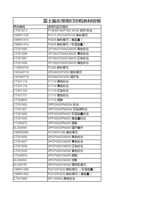
P6700 黄色硒鼓 P6700 黑色硒鼓 P6700 废粉盒 P6360 青色粉仓 P6360 红色粉仓 P6360 黄色粉仓 P6360 黑色粉仓 P6360 定影器 P6360 感光鼓 色粉仓 P7800黄色粉仓 P7800 硒鼓 P7800 废粉盒 P7800 转印带清理组件 P7800 定影器 DP2050 鼓粉单元 DP3105 粉仓 DP3105 维护套件 P3115 鼓粉单元 P3116 鼓粉单元 DP203A/204A 硒鼓 DP203A/204A 粉仓 DP210/211/181 鼓粉单元 P5500 粉仓 P5500 硒鼓 P5500 维护包 DP340A 鼓粉单元 WC4150 粉仓 WC4150 硒鼓 P4510 鼓粉单元 "P4510 维护套件,220V" 3428D 鼓粉单元 (高容量) 3428D 鼓粉单元 (标准容量)
CT201671 CT201670 CT201669 CT350894 CT201672 CT201673 CT201674 CT201675 CT350899 CT350900 CT350901 CT350902 CWAA0810 CWAA0812 CWAA0809 CT201164 CT201165 CT201166 CT201167 CT350654 CWAA0742 EL300720 EL300708 CT350682 CT350683 CT350684 CT350685 EL300729 EL300727 CT350563 CT350564 CT350565 CT350566 113R00684 113R00685 CT350251
106R01548 113R00763 008R12941 115R00064 CT200191 CT200192 CT200193 CT200194 CT350167 E3100026 CT200379 CT200381 CT200383 CT200385 CT350270 CWAA0521 CT350394 CT200655 CT200656 CT200657 CT200658 CT350395 CT350390 CT200923 CT200924 CT200925 CT200926 CT200899 CT200900 CT200901 CT200902 CT350462 CWAA0686 106R652 106R653 106R654
PL34120191000CKEC中文资料
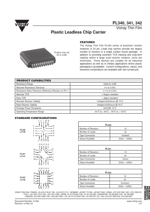
PL340 LC140
13 12 11 10 9 14 15 16 17 18 19 20 1 2 3
13 12 11 10 9 14 15 16 17 18 19 20 1 2 3 8 7 6 5 4
8 7 6 5 4
PL341 Number of Resistors Number of Leads Type Connection Values Available 19 20 Series 500Ω - 100KΩ
138
Document Number: 61066 Revision 14-Nov-02
STANDARD CONFIGURATIONS
3 2 1 20 19 4 5 6 7 8 9 10 11 12 13 18 17 16 15 14
PL340 Number of Resistors Number of Leads Type Connection Values Available 10 20 Isolated 500Ω - 100KΩ
Product may not be to scale
PRODUCT CAPABILITIES
Resistance Range Absolute Resistance Tolerance Resistance Ratio Tolerance (Reference Resistor on Pin 1) Absolute TCR Ratio TCR Absolute Resistor Stability Ratio Resistor Stability Package Power Dissipation Operating Temperature Range 500Ω to 100K 1% to 0.05% 0.1% to 0.05% ± 50ppm standard ± 5ppm standard 1000ppm/2000hours @ 70°C 300ppm/2000hours @ 70°C 500mW/ 70°C - 40°C to + 85°C, - 55°C to + 125°C
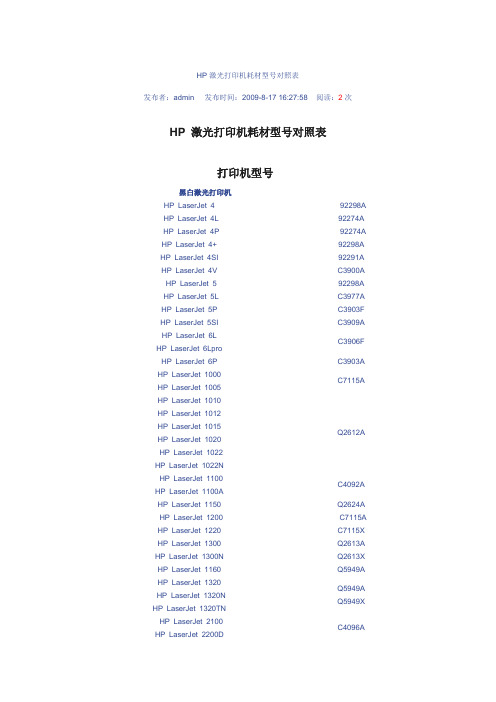
HP打印机耗材对照表
HP 激光打印机耗材型号对照表发布者:admin 发布时间:2009-8-17 16:27:58 阅读:2次HP 激光打印机耗材型号对照表打印机型号黑白激光打印机HP LaserJet 4 HP LaserJet 4L HP LaserJet 4P HP LaserJet 4+ HP LaserJet 4SI HP LaserJet 4V HP LaserJet 5 HP LaserJet 5L HP LaserJet 5P HP LaserJet 5SI92298A 92274A 92274A 92298A 92291A C3900A 92298A C3977A C3903F C3909AHP LaserJet 6LHP LaserJet 6LproC3906F HP LaserJet 6P C3903A HP LaserJet 1000HP LaserJet 1005C7115A HP LaserJet 1010HP LaserJet 1012HP LaserJet 1015HP LaserJet 1020HP LaserJet 1022HP LaserJet 1022NQ2612AHP LaserJet 1100HP LaserJet 1100AC4092AHP LaserJet 1150 HP LaserJet 1200 HP LaserJet 1220 Q2624A C7115A C7115XHP LaserJet 1300 HP LaserJet 1300N Q2613A Q2613XHP LaserJet 1160 Q5949AHP LaserJet 1320 HP LaserJet 1320N HP LaserJet 1320TN Q5949A Q5949XHP LaserJet 2100HP LaserJet 2200DC4096AHP LaserJet 2300HP LaserJet 2300DHP LaserJet 2300DNQ2610AHP LaserJet 2420 HP LaserJet 2420N HP LaserJet 2430DTN Q6511A Q6511XHP LaserJet 3015HP LaserJet 3020HP LaserJet 3030Q2612A HP LaserJet 3200 C4092AHP LaserJet 3300 HP LaserJet 3330 HP LaserJet 3380 C7115A C7115XHP LaserJet 4000 C4127AHP LaserJet 4050 HP LaserJet 4100 HP LaserJet 4100MFP HP LaserJet 4200 HP LaserJet 4250 HP LaserJet 4250N HP LaserJet 4300 C4127X C8061A C8061X Q1338A C5942A C5942X Q1339AHP LaserJet 4350N HP LaserJet 4350TN C5942A C5942XHP LaserJet 5000HP LaserJet 5000LEHP LaserJet 5100HP LaserJet 5100LEHP LaserJet 5100SEC4129XHP LaserJet 8000 HP LaserJet 8100 HP LaserJet 8150 C3909A C4182XHP LaserJet 9000HP LaserJet 9000MFPHP LaserJet 9000lmfpHP LaserJet 9050HP LaserJet 9050NHP LaserJet 9050DNC8543XHP LaserJet 9055HP LaserJet 9065Q3683C 彩色激光打印机HP Color LaserJet CLJ5C3102A 青色碳粉盒(C )C3104A 品红色碳粉盒(M )C3103A 黄色碳粉盒(Y )C3105A 黑色碳粉盒(K )C3967A 打印硒鼓HP Color LaserJet 1500L HP Color LaserJet 2500C9701A 青色硒鼓(C )C9703A 品红色硒鼓(M )C9702A 黄色碳硒鼓(Y )C9700A 黑色硒鼓(K )C9704A 成像鼓HP Color LaserJet 2550L HP Color LaserJet 2550LN HP Color LaserJet 2550N HP Color LaserJet 2820 AiO HP Color LaserJet 2840 AiOQ3961A 青色硒鼓(C )Q3963A 品红色硒鼓(M )Q3962A 黄色硒鼓(Y )Q3960A 黑色硒鼓(K )Q3971A 青色硒鼓(C )Q3973A 品红色硒鼓(M )Q3972A 黄色硒鼓(Y )Q3964A 成像鼓HP Color LaserJet 2600NQ6001A 青色硒鼓(C )Q6003A 品红色硒鼓(M )Q6002A 黄色硒鼓(Y )Q6000A 黑色硒鼓(K )HP Color LaserJet 3500 HP Color LaserJet 3500 N HP Color LaserJet 3550 HP Color LaserJet 3550NQ2671A 青色硒鼓(C )Q2673A 品红色硒鼓(M )Q2672A 黄色硒鼓(Y )Q2670A 黑色硒鼓(K )HP Color LaserJet 3700 HP Color LaserJet 3700DNQ2681A 青色硒鼓(C )Q2683A 品红色硒鼓(M )Q2682A 黄色硒鼓(Y )Q2670A 黑色硒鼓(K )HP Color LaserJet 4500 HP Color LaserJet 4550HP Color LaserJet 4550N HP Color LaserJet 4550DNC4192A 青色硒鼓(C )C4193A 品红色硒鼓(M )C4194A 黄色硒鼓(Y )C4191A 黑色硒鼓(K )C4195A 感光鼓套件HP Color LaserJet 4600HP Color LaserJet 4600DN HP Color LaserJet 4600DTN HP Color LaserJet 4650 HP Color LaserJet 4650DN HP Color LaserJet 4650DTNC9721A 青色硒鼓(C )C9723A 品红色硒鼓(M )C9722A 黄色硒鼓(Y )C9720A 黑色硒鼓(K )HP Color LaserJet 5500HP Color LaserJet 5500DN HP Color LaserJet 5500DTN HP Color LaserJet 5550 HP Color LaserJet 5500N HP Color LaserJet 5550DN HP Color LaserJet 5550DTNC9731A 青色硒鼓(C )C9733A 品红色硒鼓(M )C9732A 黄色硒鼓(Y )C9730A 黑色硒鼓(K )HP Color LaserJet 5550HDNHP Color LaserJet 8500 HP Color LaserJet 8550 HP Color LaserJet 8550N HP Color LaserJet 8550DNC4150A 青色硒鼓(C )C4151A 品红色硒鼓(M )C4152A 黄色硒鼓(Y )C4149A 黑色硒鼓(K )C4153A 感光鼓套件HP Color LaserJet 9500N HP Color LaserJet 9500HDN C8551A 青色碳粉盒(C )C8553A 品红碳粉盒(M )C8552A 黄色碳粉盒(Y )C8550A 黑色碳粉盒(K )C8561A 青色硒鼓(C )C8563A 品红色硒鼓(M )C8562A 黄色硒鼓(Y )C8560A 黑色硒鼓(K )。
PL34120191000MFEX资料
PL341 LC141
PL342 Number of Resistors Number of Leads Type Connection Values Available 19 20 Common 500Ω - 100KΩ
PL342 LC142
PACKAGED PRODUCTS NETWORKS
VISHAY THIN FILM • FRANCE +33.4.93.37.28.24 FAX: +33.4.93.37.27.31 • GERMANY +49.9287.710 FAX: +49 9287.70435 • ISRAEL +972.3.557.0945 FAX: +972.3.558.9121 • ITALY + 39.2.300.11919 FAX: +39.2.300.11999 • JAPAN +81.42.729.0661 FAX: +81.42.729.3400 • SINGAPORE +65.788.6668 FAX: +65.788.0988 • SWEDEN +46.8.594.70590 FAX: +46.8.594.70581 • UK +44 191 514 8237 FAX: +44 1953 457 722 • USA: (610) 407-4800 FAX: (610) 640-9081
C1
20 LEAD PACKAGE DIMENSIONS in inches [millimeters]
A MINIMUM 0.385 [9.78] NOMINAL 0.390 [9.91] MAXIMUM 0.395 [10.03] A1 0.348 [8.84] 0.350 [8.89] 0.352 [8.94] B 0.385 [9.78] 0.390 [9.91] 0.395 [10.03] B1 0.348 [8.84] 0.350 [8.89] 0.352 [8.94] C --0.045 [1.14] --C1 --0.045 [1.14] --D --0.015 [0.38] --D1 --0.015 [0.38] --E ------F --0.178 [4.52] --G --0.108 [2.74] --I 0.026 0.66 ----J --P ---
CA3420中文资料

PARAMETER
TEST SYMBOL CONDITIONS
CA3420
MIN
TYP
MAX
CA3420A
MIN
TYP
MAX
UNITS
Input Offset Voltage Input Offset Current (Note 3) Input Current (Note 3) Large Signal Voltage Gain
Functional Diagram
X1
-
MOS BIPOLAR +
X1
BUFFER AMPS; BOOTSTRAPPED INPUT PROTECTION
NETWORK
HIGH GAIN (50K)
MOS BIPOLAR
OTA BUFFER (X2)
PiP VIEW
To V+
I8-
20
20
2
2
UNITS TΩ pF Ω
nV/√Hz nV/√Hz
mA mA MHz V/µs µs % µA mA
Electrical Specifications For Equipment Design, At VSUPPLY = ±1V, TA = 25oC, Unless Otherwise Specified
|VIO| |IIO| |II| AOL
RL = 10kΩ
-
5
10
-
0.01
4
-
1
5
10
100
-
80
100
-
-
2
-
0.01
-
0.02
20
100
86
rp3440

第6版
生产部件号: A7137-96001-zh_cn 2005 年 4 月
© 版权所有 2004-2005 Hewlett-Packard Development Company, L.P.
法律声明
版权声明。 版权所有 2004-2005 Hewlett-Packard Development Company, L.P.。 本文档所包含的信息如有更改,恕不另行通知。 随 HP 产品及服务提供的明示性担保声明中列出了适用于此 HP 产品及服务的专用担保条款。本文中的任何内容均 不构成额外的担保。 HP 对本文中的技术或编辑错误以及缺漏不负任. 服务器概述和拆封
服务器概述 . . . . . . . . . . . . . . . . . . . . . . . . . . . . . . . . . . . . . . . . . . . . . . . . . . . . . . . . . . . . . . . . . . . . . . . . . . . . . . . . . . . 11 打开服务器包装 . . . . . . . . . . . . . . . . . . . . . . . . . . . . . . . . . . . . . . . . . . . . . . . . . . . . . . . . . . . . . . . . . . . . . . . . . . . . . . .13 打开未安装机架的服务器包装 . . . . . . . . . . . . . . . . . . . . . . . . . . . . . . . . . . . . . . . . . . . . . . . . . . . . . . . . . . . . . . . . .13 将 HP 服务器安装到机架上. . . . . . . . . . . . . . . . . . . . . . . . . . . . . . . . . . . . . . . . . . . . . . . . . . . . . . . . . . . . . . . . . . . .13 将塔式服务器改为机架式或将机架式服务器改为塔式 . . . . . . . . . . . . . . . . . . . . . . . . . . . . . . . . . . . . . . . . . . . . .14
圆形插头

18
M12x1 插座 (母头), 系列 CN2 ▶ 插座, M12x1, 5-針, A-编码
19
M12x1 插座 (母头), 系列 CN2 ▶ 插座, M12x1, 5-針, A-编码 ▶ 屏蔽
20
M12x1 插座 (母头), 系列 CN2 ▶ 插座, M12x1, 5-針, B-编码 ▶ 屏蔽
聚酯树脂 氟(石炭)橡胶(FKM)
技术性备注 ■ 规定的保护等级只适用于已安装和检查的状态。
额定电压 电流,最大值
AC
[V]
[A]
240
4
电缆引线 可连接的电缆的最 小/最大直径
直线 180° 呈 90° 弯角
[mm] 4/8
外壳颜色 黑色
重量
注
产品代码
[kg] 0,028 0,027
Fig. 1 Fig. 2
1
BN
3 4
BU BK
产品代码
1834484173 1834484174
额定电压 电流,最大值
DC
AC
[V]
[V]
[A]
75
60
4
安装位置
位置1
电极数目 3
电缆引线 可连接的电缆的 最小/最大直径
直线 180°
[mm]
呈 90° 弯角
-- / 4,5
产品代码 1834484173 1834484174
8941054324 8941054424
Fig. 1
52,5
1
4 2 3
额定电压
电流,最大值
DC
AC
[V]
[V]
[A]
75
60
4
电缆引线 直线 180°
派克笔生产代码

MADE NI UK 是產自英國的意思後面的“III I”是它的生產代碼包括年份、季度代碼表如下Year Q1 Q2 Q3 Q4---------------------------------1970 - QE QC QL QI1971 - UE UC UL UI1972 - AE AC AL AI1973 - LE LC LL LI1974 - IE IC IL II Note that EI could also denote Q1 1984 or Q3 1988 etc 1975 - TE TC TL TI1976 - YE YC YL YI1977 - PE PC PL PI1978 - EE EC EL EI1979 - NE NC NL NI Date coding begins in the US1980 - QE QC QL QI1981 - UE UC UL UI1982 - AE AC AL AI1983 - LE LC LL LI1984 - IE IC IL II Note that EI could also denote Q1 1974 or Q3 1988 etc 1985 - TE TC TL TI1986 - YE YC YL YI(change)1987 - IIIP IIP IP P1988 - IIIE IIE IE E Note that EI could also denote Q1 1974 or Q1 1984 etc 1989 - IIIN IIN IN N1990 - IIIQ IIQ IQ Q1991 - IIIU IIU IU U1992 - IIIA IIA IA A1993 - IIIL IIL IL L1994 - IIII III II I1995 - IIIT IIT IT T1996 - IIIY IIY IY Y1997 - IIIP IIP IP P1998 - IIIE IIE IE E1999 - IIIN IIN IN N(change)2000 - Q.III Q.II Q.I Q2003 - L.III L.II L.I L2004 - I.III I.II I.I I2005 - T.III T.II T.I T2006 - Y.III Y.II Y.I Y2007 - P.III P.II P.I P2008 - E.III E.II E.I E2009 - N.III N.II N.I N[此文档可自行编辑修改,如有侵权请告知删除,感谢您的支持,我们会努力把内容做得更好]。
- 1、下载文档前请自行甄别文档内容的完整性,平台不提供额外的编辑、内容补充、找答案等附加服务。
- 2、"仅部分预览"的文档,不可在线预览部分如存在完整性等问题,可反馈申请退款(可完整预览的文档不适用该条件!)。
- 3、如文档侵犯您的权益,请联系客服反馈,我们会尽快为您处理(人工客服工作时间:9:00-18:30)。
C1
20 LEAD PACKAGE DIMENSIONS in inches [millimeters]
A MINIMUM 0.385 [9.78] NOMINAL 0.390 [9.91] MAXIMUM 0.395 [10.03] A1 0.348 [8.84] 0.350 [8.89] 0.352 [8.94] B 0.385 [9.78] 0.390 [9.91] 0.395 [10.03] B1 0.348 [8.84] 0.350 [8.89] 0.352 [8.94] C --0.045 [1.14] --C1 --0.045 [1.14] --D --0.015 [0.38] --D1 --0.015 [0.38] --E ------F --0.178 [4.52] --G --0.108 [2.74] --I 0.026 0.66 ----J --P ---
Document Number: 61066 Revision 14-Nov-02
137
元器件交易网
PL340, 341, 342
Vishay Thin Film
PACKAGE OUTLINE DRAWING PLASTIC LEADLESS CHIP CARRIER PL340
0.050 inches 4° typical 0.5° typical B1 FP G 4° typical J A, B 0.120” DIAMETER 0.003 - 0.004” DEPTH A1 0.027 inches
Plastic Leadless Chip CarD1
138
Document Number: 61066 Revision 14-Nov-02
元器件交易网
PL340, 341, 342
Vishay Thin Film
Plastic Leadless Chip Carrier
FEATURES
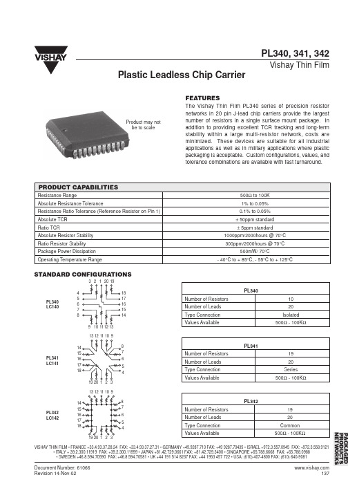
The Vishay Thin Film PL340 series of precision resistor networks in 20 pin J-lead chip carriers provide the largest number of resistors in a single surface mount package. In addition to providing excellent TCR tracking and long-term stability within a large multi-resistor network, costs are minimized. These devices are suitable for all industrial applications as well as in military applications where plastic packaging is acceptable. Custom configurations, values, and tolerance combinations are available with fast turnaround.
PACKAGED PRODUCTS NETWORKS
VISHAY THIN FILM • FRANCE +33.4.93.37.28.24 FAX: +33.4.93.37.27.31 • GERMANY +49.9287.710 FAX: +49 9287.70435 • ISRAEL +972.3.557.0945 FAX: +972.3.558.9121 • ITALY + 39.2.300.11919 FAX: +39.2.300.11999 • JAPAN +81.42.729.0661 FAX: +81.42.729.3400 • SINGAPORE +65.788.6668 FAX: +65.788.0988 • SWEDEN +46.8.594.70590 FAX: +46.8.594.70581 • UK +44 191 514 8237 FAX: +44 1953 457 722 • USA: (610) 407-4800 FAX: (610) 640-9081
0.320 0.150 [8.13] [3.81] -----
ORDERING INFORMATION
Example: PL340-20-10-1000-F-F-B-C, 20 Lead PLCC, 1000Ω Isolated Resistors, Absolute Tolerance: 1.0%, Ratio Tolerance: 0.1%, Absolute TCR: 25ppm/°C, Ratio TCR: 2ppm/°C. PL340 20 10 1000 F F B C MODEL NUMBER OF NUMBER OF RESISTANCE ABSOLUTE RATIO ABSOLUTE TCR RATIO TCR LEADS RESISTORS VALUE TOLERANCE TOLERANCE PPM/°C PPM/°C % % (To RREF) The first 3 digits are significant PL341 B = 0.1* D = 0.050* B = 25 C = 2* figures and the last specifies the PL342 C = 0.2* F = 0.100 D = 50 D = 3* number of zeros to follow. D = 0.5 H = 0.250 E = 100 F = 5* “R” designates the decimal F = 1.0 J = 0.500 G = 10 point. G = 2.0 K = 1.000 X = N/A Example: 100 ohms = 1000 J = 5.0 X = N/A 1000 ohms = 1001 K = 10.0 M = 20.0 *Value dependent NOTE: Factory will covert order number into final part number.
Product may not be to scale
PRODUCT CAPABILITIES
Resistance Range Absolute Resistance Tolerance Resistance Ratio Tolerance (Reference Resistor on Pin 1) Absolute TCR Ratio TCR Absolute Resistor Stability Ratio Resistor Stability Package Power Dissipation Operating Temperature Range 500Ω to 100K 1% to 0.05% 0.1% to 0.05% ± 50ppm standard ± 5ppm standard 1000ppm/2000hours @ 70°C 300ppm/2000hours @ 70°C 500mW/ 70°C - 40°C to + 85°C, - 55°C to + 125°C
PL341 LC141
PL342 Number of Resistors Number of Leads Type Connection Values Available 19 20 Common 500Ω - 100KΩ
PL342 LC142
PACKAGED PRODUCTS NETWORKS
VISHAY THIN FILM • FRANCE +33.4.93.37.28.24 FAX: +33.4.93.37.27.31 • GERMANY +49.9287.710 FAX: +49 9287.70435 • ISRAEL +972.3.557.0945 FAX: +972.3.558.9121 • ITALY + 39.2.300.11919 FAX: +39.2.300.11999 • JAPAN +81.42.729.0661 FAX: +81.42.729.3400 • SINGAPORE +65.788.6668 FAX: +65.788.0988 • SWEDEN +46.8.594.70590 FAX: +46.8.594.70581 • UK +44 191 514 8237 FAX: +44 1953 457 722 • USA: (610) 407-4800 FAX: (610) 640-9081
STANDARD CONFIGURATIONS
3 2 1 20 19 4 5 6 7 8 9 10 11 12 13 18 17 16 15 14
PL340 Number of Resistors Number of Leads Type Connection Values Available 10 20 Isolated 500Ω - 100KΩ
PL340 LC140
13 12 11 10 9 14 15 16 17 18 19 20 1 2 3
13 12 11 10 9 14 15 16 17 18 19 20 1 2 3 8 7 6 5 4
8 7 6 5 4
PL341 Number of Resistors Number of Leads Type Connection Values Available 19 20 Series 500Ω - 100KΩ
