IRFP中文资料
IRFP4004PBF中文资料

IGSS
Gate-to-Source Forward Leakage
Gate-to-Source Reverse Leakage
40 ––– ––– V VGS = 0V, ID = 250µA
––– 0.035 ––– V/°C Reference to 25°C, ID = 5mAd
––– 1.35 1.70 mΩ VGS = 10V, ID = 195A g
Capability
IRFP4004PbF
HEXFET® Power MOSFET
D
VDSS
RDS(on) typ.
max.
ID (Silicon Limited)
S
ID (Package Limited)
40V 1.35mΩ 1.70mΩ 350Ac
195A
D
S D G TO-247AC
G
Gate
Coss while VDS is rising from 0 to 80% VDSS. When mounted on 1" square PCB (FR-4 or G-10 Material). For recom
mended footprint and soldering techniques refer to application note #AN-994. Rθ is measured at TJ approximately 90°C.
Dynamic @ TJ = 25°C (unless otherwise specified)
Symbol
Parameter
Min. Typ. Max. Units
Conditions
gfs Qg Qgs Qgd Qsync
IRFP4110PBF中文资料

Linear Derating Factor
VGS
Gate-to-Source Voltage
dv/dt TJ TSTG
Peak Diode Recovery f Operating Junction and Storage Temperature Range
Soldering Temperature, for 10 seconds
mended footprint and soldering techniques refer to application note #AN-994. Rθ is measured at TJ approximately 90°C.
2
元器件交易网
td(on)
Turn-On Delay Time
––– 25 –––
tr
Rise Time
––– 67 –––
td(off)
Turn-Off Delay Time
––– 78 –––
tf
Fall Time
––– 88 –––
Ciss
Input Capacitance
––– 9620 –––
Coss
Output Capacitance
Coss eff. (ER) is a fixed capacitance that gives the same energy as
Coss while VDS is rising from 0 to 80% VDSS. When mounted on 1" square PCB (FR-4 or G-10 Material). For recom
ID, Drain-to-Source Current (A)
IRFP254中文资料
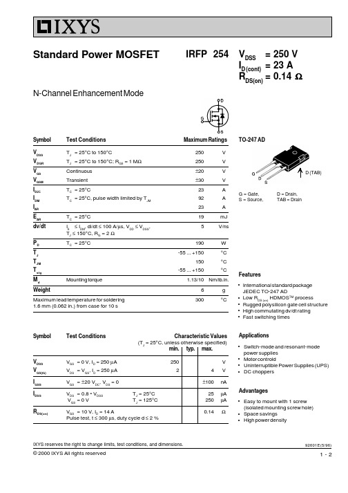
Repetitive; pulse width limited by TJM IF = IS, VGS = 0 V, Pulse test, t ≤ 300 µs, duty cycle d ≤ 2 % IF = IS, -di/dt = 100 A/µs, VR = 100 V
© 2000 IXYS All rights reserved
Features International standard package JEDEC TO-247 AD Low RDS (on) HDMOSTM process Rugged polysilicon gate cell structure High commutating dv/dt rating Fast switching times
Test Conditions TJ = 25°C to 150°C TJ = 25°C to 150°C; RGS = 1 MΩ Continuous Transient TC = 25°C TC = 25°C, pulse width limited by TJM TC = 25°C IS ≤ IDM, di/dt ≤ 100 A/µs, VDD ≤ VDSS, TJ ≤ 150°C, RG = 2 Ω TC = 25°C
VDSS VGS(th) IGSS IDSS R DS(on)
VGS = 0 V, ID = 250 µA VDS = VGS, ID = 250 µA VGS = ±20 VDC, VDS = 0 VDS = 0.8 • VDSS VGS = 0 V
Advantages Easy to mount with 1 screw (isolated mounting screw hole) Space savings High power density
IRFP250中文资料
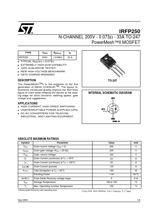
1/8Sep 2000IRFP250N-CHANNEL 200V - 0.073Ω - 33A TO-247PowerMesh™II MOSFETs TYPICAL R DS (on) = 0.073Ωs EXTREMELY HIGH dv/dt CAPABILITY s 100% AVALANCHE TESTEDs NEW HIGH VOLTAGE BENCHMARK sGATE CHARGE MINIMIZEDDESCRIPTIONThe PowerMESH ™II is the evolution of the first generation of MESH OVERLAY ™. The layout re-finements introduced greatly improve the Ron*area figure of merit while keeping the device at the lead-ing edge for what concerns swithing speed, gate charge and ruggedness.APPLICATIONSs HIGH CURRENT, HIGH SPEED SWITCHING s UNINTERRUPTIBLE POWER SUPPLIES (UPS)s DC-AC CONVERTERS FOR TELECOM, INDUSTRIAL, AND LIGHTING EQUIPMENTABSOLUTE MAXIMUM RATINGS(•)Pulse width limited by safe operating areaTYPE V DSS R DS(on)I D IRFP250200V< 0.085Ω33 ASymbol ParameterValue Unit V DS Drain-source Voltage (V GS = 0)200V V DGR Drain-gate Voltage (R GS = 20 k Ω)200V V GS Gate- source Voltage±20V I D Drain Current (continuos) at T C = 25°C 33A I D Drain Current (continuos) at T C = 100°C 20A I DM (q )Drain Current (pulsed)132A P TOT Total Dissipation at T C = 25°C180W Derating Factor1.44W/°C dv/dt(1)Peak Diode Recovery voltage slope 5V/ns T stg Storage Temperature–65 to 150°C T jMax. Operating Junction Temperature150°C(1)I SD ≤33A, di/dt ≤300A/µs, V DD ≤ V (BR)DSS , T j ≤ T JMAX.IRFP2502/8THERMAL DATAAVALANCHE CHARACTERISTICSELECTRICAL CHARACTERISTICS (TCASE = 25 °C UNLESS OTHERWISE SPECIFIED)OFFON (1)DYNAMICRthj-case Thermal Resistance Junction-case Max 0.66°C/W Rthj-amb Thermal Resistance Junction-ambient Max 30°C/W Rthc-sinkThermal Resistance Case-sink Typ0.1°C/W T lMaximum Lead Temperature For Soldering Purpose300°CSymbol ParameterMax ValueUnit I AR Avalanche Current, Repetitive or Not-Repetitive (pulse width limited by T j max)33A E ASSingle Pulse Avalanche Energy(starting T j = 25 °C, I D = I AR , V DD = 50 V)600mJSymbol ParameterTest ConditionsMin.Typ.Max.Unit V (BR)DSS Drain-sourceBreakdown Voltage I D = 250 µA, V GS = 0200V I DSS Zero Gate VoltageDrain Current (V GS = 0)V DS = Max Rating1µA V DS = Max Rating, T C = 125 °C 50µA I GSSGate-body Leakage Current (V DS = 0)V GS = ±30V±100nASymbol ParameterTest ConditionsMin.Typ.Max.Unit V GS(th)Gate Threshold Voltage V DS = V GS , I D = 250 µA 234V R DS(on)Static Drain-source On ResistanceV GS = 10V, I D = 16A 0.0730.085ΩI D(on)On State Drain CurrentV DS > I D(on) x R DS(on)max, V GS =10V33ASymbol ParameterTest ConditionsMin.Typ.Max.Unit g fs Forward Transconductance V DS > I D(on) x R DS(on)max,I D = 16A1025S C iss Input Capacitance V DS = 25V, f = 1 MHz, V GS = 02850pF C oss Output Capacitance 420pF C rssReverse Transfer Capacitance120pF3/8IRFP250ELECTRICAL CHARACTERISTICS (CONTINUED)SWITCHING ONSWITCHING OFFSOURCE DRAIN DIODENote: 1.Pulsed: Pulse duration = 300 µs, duty cycle 1.5 %.2.Pulse width limited by safe operating area.Symbol ParameterTest ConditionsMin.Typ.Max.Unit t d(on)Turn-on Delay Time V DD = 100V, I D =16 A R G =4.7Ω, V GS = 10V (see test circuit, Figure 3)25ns t r Rise Time 50ns Q g Total Gate Charge V DD = 160V, I D = 33 A,V GS = 10V, R G =4.7Ω117158nC Q gs Gate-Source Charge 15nC Q gdGate-Drain Charge50nCSymbol ParameterTest ConditionsMin.Typ.Max.Unit t r(Voff)Off-voltage Rise TimeV DD = 160V, I D = 16 A, R G =4.7Ω, V GS = 10V (see test circuit, Figure 5)60ns t f Fall Time 40ns t cCross-over Time100nsSymbol ParameterTest ConditionsMin.Typ.Max.Unit I SD Source-drain Current 33A I SDM (2)Source-drain Current (pulsed)132A V SD (1)Forward On Voltage I SD = 33 A, V GS = 0 1.6V t rr Reverse Recovery Time I SD = 33 A, di/dt = 100A/µs, V DD = 100V, T j = 150°C (see test circuit, Figure 5)370ns Q rr Reverse Recovery Charge 5.4µC I RRMReverse Recovery Current29AIRFP2504/85/8IRFP250Normalized On Resistance vs TemperatureIRFP2506/8Fig. 5: Test Circuit For Inductive Load Switching And Diode Recovery TimesFig. 4: Gate Charge test CircuitFig. 2: Unclamped Inductive WaveformFig. 1:Unclamped Inductive Load Test CircuitFig. 3: Switching Times Test Circuit ForResistive LoadIRFP2507/8IRFP2508/8Information furnished is believed to be accurate and reliable. However, STMicroelectronics assumes no responsibility for the consequences of use of such information nor for any infringement of patents or other rights of third parties which may result from its use. No license is granted by implication or otherwise under any patent or patent rights of STMicroelectronics. Specification mentioned in this publication are subject to change without notice. This publication supersedes and replaces all information previously supplied. STMicroelectronics products are not authorized for use as critical components in life support devices or systems without express written approval of STMicroelectronics.The ST logo is a trademark of STMicroelectronics© 2000 STMicroelectronics – Printed in Italy – All Rights ReservedSTMicroelectronics GROUP OF COMPANIESAustralia - Brazil - China - Finland - France - Germany - Hong Kong - India - Italy - Japan - Malaysia - Malta - Morocco -Singapore - Spain - Sweden - Switzerland - United Kingdom - U.S.A.。
irfp结构式
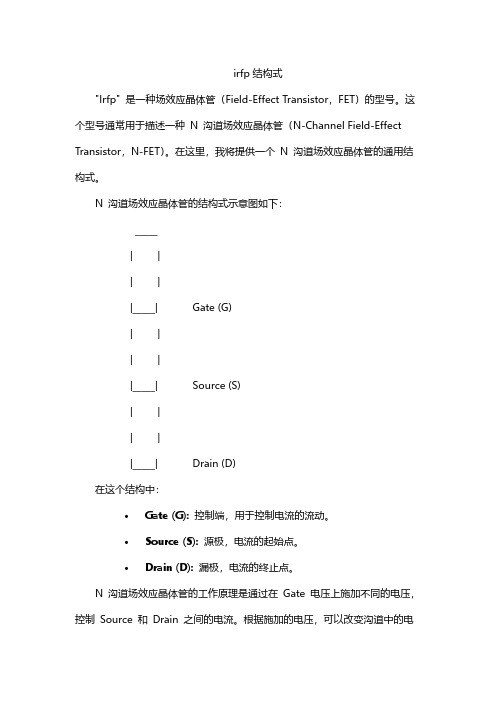
irfp结构式
"Irfp" 是一种场效应晶体管(Field-Effect Transistor,FET)的型号。
这个型号通常用于描述一种N 沟道场效应晶体管(N-Channel Field-Effect Transistor,N-FET)。
在这里,我将提供一个N 沟道场效应晶体管的通用结构式。
N 沟道场效应晶体管的结构式示意图如下:
_____
| |
| |
|_____| Gate (G)
| |
| |
|_____| Source (S)
| |
| |
|_____| Drain (D)
在这个结构中:
•Gate (G):控制端,用于控制电流的流动。
•Source (S):源极,电流的起始点。
•Drain (D):漏极,电流的终止点。
N 沟道场效应晶体管的工作原理是通过在Gate 电压上施加不同的电压,控制Source 和Drain 之间的电流。
根据施加的电压,可以改变沟道中的电
荷分布,从而控制电流的流动。
请注意,实际的晶体管结构可能会因制造商、型号和用途而有所不同。
IRFP9140N中文资料
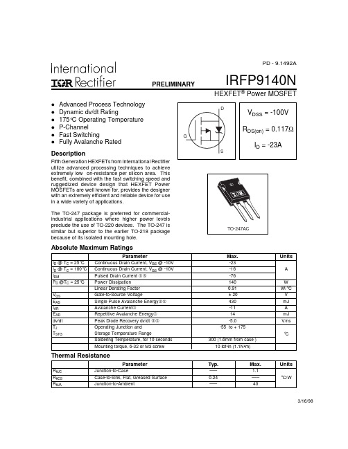
Starting TJ = 25°C, L = 7.1mH
RG = 25Ω, IAS = -11A. (See Figure 12)
ISD ≤ -11A, di/dt ≤ -470A/µs, VDD ≤ V(BR)DSS,
TJ ≤ 175°C
元器件交易网
IRFP9140N
元器件交易网
PD - 9.1492A
PRELIMINARY
l l l l l l
IRFP9140N
HEXFET® Power MOSFET
D
Advanced Process Technology Dynamic dv/dt Rating 175°C Operating Temperature P-Channel Fast Switching Fully Avalanche Rated
Source-Drain Ratings and Characteristics
IS
ISM
VSD trr Qrr ton Notes:
Parameter Continuous Source Current (Body Diode) Pulsed Source Current (Body Diode) Diode Forward Voltage Reverse Recovery Time Reverse RecoveryCharge Forward Turn-On Time
I D = -19A
-I D , D rain-to -S o urc e C urre nt (A )
2.0
1.5
1.0
1
0.5
0.1 4 5 6 7
V D S = -2 5 V 2 0 µ s P U L S E W ID T H
IRFP3710中文资料
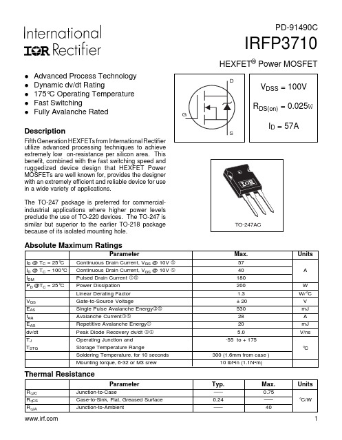
IRFP3710HEXFET ® Power MOSFETFifth Generation HEXFETs from International Rectifier utilize advanced processing techniques to achieve extremely low on-resistance per silicon area. This benefit, combined with the fast switching speed and ruggedized device design that HEXFET Power MOSFETs are well known for, provides the designer with an extremely efficient and reliable device for use in a wide variety of applications.The TO-247 package is preferred for commercial-industrial applications where higher power levels preclude the use of TO-220 devices. The TO-247 is similar but superior to the earlier TO-218 packagebecause of its isolated mounting hole.l Advanced Process Technology l Dynamic dv/dt Ratingl 175°C Operating Temperature l Fast SwitchinglFully Avalanche RatedDescriptionParameterMax.UnitsI D @ T C = 25°C Continuous Drain Current, V GS @ 10V 57I D @ T C = 100°C Continuous Drain Current, V GS @ 10V 40A I DMPulsed Drain Current 180P D @T C = 25°C Power Dissipation 200W Linear Derating Factor 1.3W/°C V GS Gate-to-Source Voltage± 20V E AS Single Pulse Avalanche Energy 530mJ I AR Avalanche Current28A E AR Repetitive Avalanche Energy 20mJ dv/dt Peak Diode Recovery dv/dt 5.0V/ns T J Operating Junction and-55 to + 175T STGStorage Temperature RangeSoldering Temperature, for 10 seconds 300 (1.6mm from case )°CMounting torque, 6-32 or M3 srew10 lbf•in (1.1N•m)Absolute Maximum RatingsParameterTyp.Max.UnitsR q JC Junction-to-Case–––0.75R q CS Case-to-Sink, Flat, Greased Surface 0.24–––°C/WR q JAJunction-to-Ambient–––40Thermal Resistance 1PD-91490CIRFP3710IRFP3710IRFP3710IRFP3710IRFP3710IRFP3710IRFP3710。
IRFP3703中文资料
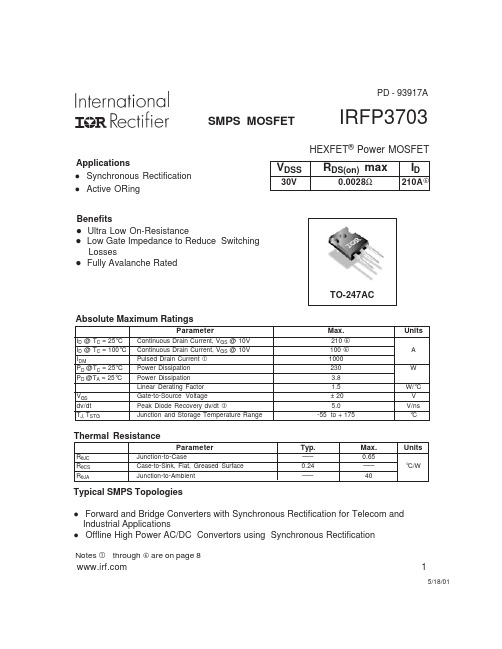
Min. Typ. Max. Units ––– ––– ––– ––– ––– ––– 210 A ––– 1000 0.8 80 185 1.3 120 275 V ns nC
Conditions D MOSFET symbol showing the G integral reverse S p-n junction diode. TJ = 25°C, IS = 76A, VGS = 0V TJ = 25°C, IF = 76A, V DS = 16V di/dt = 100A/µs
元器件交易网
PD - 93917A
SMPS MOSFET
IRFP3703
HEXFET® Power MOSFET
Applications l Synchronous Rectification l Active ORing Benefits l Ultra Low On-Resistance l Low Gate Impedance to Reduce Switching Losses l Fully Avalanche Rated
Typ.
––– 0.24 –––
Max.
0.65 ––– 40
Units
°C/W
Typical SMPS Topologies
l l
Forward and Bridge Converters with Synchronous Rectification for Telecom and Industrial Applications Offline High Power AC/DC Convertors using Synchronous Rectification
Avalanche Characteristics
IRFP9240中文资料

Ordering InformatioND
IRFP9240
TO-247
IRFP9240
NOTE: When ordering, use the entire part number.
Features
Internal Source Inductance
BVDSS VGS(TH)
IDSS
ID(ON) IGSS rDS(ON) gfs td(ON)
tr td(OFF)
tf Qg(TOT)
Qgs Qgd CISS COSS CRSS LD
LS
ID = -250µA, VGS = 0V (Figure 10) VGS = VDS, ID = -250µA VDS = Rated BVDSS, VGS = 0V VDS = 0.8 x Rated BVDSS, VGS = 0V, TJ = 125oC VDS > ID(ON) x rDS(ON)MAX, VGS = -10V VGS = ±20V ID = -6.3A, VGS = -10V (Figures 8, 9) VDS ≤ -50V, ID = -6.3A (Figure 12) VDD = -100V, ID ≈ -12A, RG = 9.1Ω, VGS = -10V, RL = 7.6Ω, (Figures 17, 18) MOSFET Switching Times are Essentially Independent of Operating Temperature
• 12A, 200V • rDS(ON) = 0.500Ω • Single Pulse Avalanche Energy Rated • SOA is Power Dissipation Limited • Nanosecond Switching Speeds • Linear Transfer Characteristics • High Input Impedance
IRFP450中文资料

IRFP450N -CHANNEL 500V -0.33Ω-14A -TO-247PowerMESH ™MOSFETs TYPICAL R DS(on)=0.33Ωs EXTREMELY HIGH dv/dt CAPABILITY s 100%AVALANCHE TESTEDs VERY LOW INTRINSIC CAPACITANCES sGATE CHARGE MINIMIZEDDESCRIPTIONThis power MOSFET is designed using the company’s consolidated strip layout-based MESH OVERLAY ™process.This technology matches and improves the performances compared with standard parts from various sources.APPLICATIONS s HIGH CURRENT SWITCHING s UNINTERRUPTIBLE POWER SUPPLY (UPS)s DC/DC COVERTERS FOR TELECOM,INDUSTRIAL,AND LIGHTING EQUIPMENT.®INTERNAL SCHEMATIC DIAGRAMAugust 1998ABSOLUTE MAXIMUM RATINGSSymbol ParameterValue Unit V DS Drain-source Voltage (V GS =0)500V V DGR Drain-gate Voltage (R GS =20k Ω)500V V GS Gate-source Voltage±20V I D Drain Current (continuous)at T c =25oC 14A ID Drain Current (continuous)at T c =100o C 8.7A I DM (•)Drain Current (pulsed)56A P t ot Total Dissipation at T c =25oC 190W Derating Factor1.5W/oC dv/dt(1)Peak Diode Recovery voltage slope 3.5V/nsT stg Storage Temperature-65to 150o C T jMax.Operating Junction Temperature150o C(•)Pulse width limited by safe operating area(1)I SD ≤14A,di/dt ≤130A/µs,V DD ≤V (BR)DSS ,Tj ≤T JMAXTYPE V DSS R DS(on)I D IRFP450500V<0.4Ω14A123TO-2471/8THERMAL DATAR t hj-ca se Rthj-amb R thc-si nkT l Thermal Resistance Junction-case MaxThermal Resistance Junction-ambient MaxThermal Resistance Case-sink TypMaximum Lead Temperature For Soldering Purpose0.66300.1300o C/WoC/Wo C/Wo CAVALANCHE CHARACTERISTICSSymbol Parameter Max Value UnitI AR Avalanche Current,Repetitive or Not-Repetitive(pulse width limited by T j max)14AE AS Single Pulse Avalanche Energy(starting T j=25o C,I D=I AR,V DD=50V)800mJELECTRICAL CHARACTERISTICS(T case=25o C unless otherwise specified)OFFSymbol Parameter Test Conditions Min.Typ.Max.Unit V(BR)DSS Drain-sourceBreakdown VoltageI D=250µA V GS=0500VI DSS Zero Gate VoltageDrain Current(V GS=0)V DS=Max RatingV DS=Max Rating T c=125o C150µAµAI GSS Gate-body LeakageCurrent(V DS=0)V GS=±20V±100nA ON(∗)Symbol Parameter Test Conditions Min.Typ.Max.Unit V GS(th)Gate ThresholdVoltageV DS=V GS I D=250µA234VR DS(on)Static Drain-source OnResistanceV GS=10V I D=8.4A0.330.4ΩI D(o n)On State Drain Current V DS>I D(on)x R DS(on)maxV GS=10V14A DYNAMICSymbol Parameter Test Conditions Min.Typ.Max.Unitg fs(∗)ForwardTransconductanceV DS>I D(on)x R DS(on)max I D=8.4A9.313SC iss C oss C rss Input CapacitanceOutput CapacitanceReverse TransferCapacitanceV DS=25V f=1MHz V GS=0260033040pFpFpFIRFP450 2/8ELECTRICAL CHARACTERISTICS(continued)SWITCHING ONSymbol Parameter Test Conditions Min.Typ.Max.Unitt d(on) t r Turn-on TimeRise TimeV DD=250V I D=7AR G=4.7 ΩV GS=10V(see test circuit,figure1)2414nsnsQ g Q gs Q gd Total Gate ChargeGate-Source ChargeGate-Drain ChargeV DD=400V I D=14A V GS=10V7513.527nCnCnCSWITCHING OFFSymbol Parameter Test Conditions Min.Typ.Max.Unitt r(Vof f) t ft c Off-voltage Rise TimeFall TimeCross-over TimeV DD=400V I D=14AR G=4.7 ΩV GS=10V(see test circuit,figure3)152535nsnsnsSOURCE DRAIN DIODESymbol Parameter Test Conditions Min.Typ.Max.UnitI SD I SDM(•)Source-drain CurrentSource-drain Current(pulsed)1456AAV SD(∗)Forward On Voltage I SD=14A V GS=0 1.4Vt rr Q rr I RRM Reverse RecoveryTimeReverse RecoveryChargeReverse RecoveryCurrentI SD=14A di/dt=100A/µsV DD=100V T j=150o C(see test circuit,figure3)680926nsµCA(∗)Pulsed:Pulse duration=300µs,duty cycle1.5%(•)Pulse width limited by safe operating areaSafe Operating Area Thermal ImpedanceIRFP4503/8Output Characteristics TransconductanceGate Charge vs Gate-source Voltage Transfer CharacteristicsStatic Drain-source On Resistance Capacitance VariationsIRFP450 4/8Normalized Gate Threshold Voltage vs TemperatureSource-drain Diode Forward Characteristics Normalized On Resistance vs TemperatureIRFP4505/8Fig.1:Unclamped Inductive Load Test Circuit Fig.3:Switching Times Test Circuits For Resistive Load Fig.1:Unclamped Inductive Waveform Fig.4:Gate Charge test CircuitFig.5:Test Circuit For Inductive Load Switching And Diode Recovery TimesIRFP4506/8DIM.mm inch MIN.TYP.MAX.MIN.TYP.MAX.A 4.7 5.30.1850.209D 2.2 2.60.0870.102E 0.40.80.0160.031F 1 1.40.0390.055F32 2.40.0790.094F433.40.1180.134G 10.90.429H 15.315.90.6020.626L 19.720.30.7760.779L314.214.80.5590.4130.582L434.6 1.362L5 5.50.217M 230.0790.118Dia3.55 3.650.1400.144P025PTO-247MECHANICAL DATAIRFP4507/8Information furnished is believed to be accurate and reliable.However,STMicroelectronics assumes no responsibility for the consequences of use of such information nor for any infringement of patents or other rights of third parties which may result from its use.No license is granted by implication or otherwise under any patent or patent rights of STMicroelectronics.Specification mentioned in this publication are subject to change without notice.This publication supersedes and replaces all information previously supplied.STMicroelectronics products are not authorized for use as critical components in life support devices or systems without express written approval of STMicroelectronics.The ST logo is a registered trademark of STMicroelectronics ©1998STMicroelectronics –Printed in Italy –All Rights ReservedSTMicroelectronics GROUP OF COMPANIESAustralia -Brazil -Canada -China -France -Germany -Italy -Japan -Korea -Malaysia -Malta -Mexico -Morocco -The Netherlands -Singapore -Spain -Sweden -Switzerland -Taiwan -Thailand -United Kingdom -U.S.A..IRFP4508/8。
irfp4227中文参数
irfp4227中文参数IRFP4227是一款功率场效应管,广泛应用于高频功率放大器、换流器、稳压器等领域。
本文将从以下几个方面介绍IRFP4227中文参数。
一、型号解析IRFP4227是一款单N沟道MOSFET,采用TO-247AC封装,可承受150V电压和88A电流。
其最大漏极电阻为1.5mΩ,最大功耗为330W。
二、管子结构IRFP4227管子由栅极、漏极和源极三个端口组成。
其中,栅极用于控制漏极与源极之间的电阻,通过输入不同的电压自动调节导通通道,从而实现对电路的控制。
漏极和源极用于承受电流,在电路中起到导电的作用。
IRFP4227的大漏极面积可以减小串联电阻,提高开关速度,降低开关损耗,避免过热。
三、电气参数IRFP4227电气参数具有以下特点:1.额定漏极电压:150V2.额定漏极电流:88A3.最大漏极电阻:1.5mΩ4.最小门电容:3475pF5.静态漏极-源极电容:1440pF四、性能指标IRFP4227的主要性能指标如下:1.最大功耗:330W2.峰值漏极电流:352A3.漏极-源极最大耐受电压:100V4.击穿电压:±30V5.阈值电压:2-4V五、应用范围IRFP4227广泛应用于高频功率放大器、换流器、稳压器等领域。
在功率放大器领域中,IRFP4227常常被用于强电流驱动电路中的开关管,能够提高输出功率、稳定性和效率。
在稳压器领域中,IRFP4227主要应用于开关电源、DC-DC转换器等电路中,可以提高电路效率和稳定性,保护负载和电源不受过压、过流和过载的影响。
以上就是关于IRFP4227中文参数的介绍,希望能够帮助大家更好地了解和使用这款功率场效应管。
IRFP264N中文资料

ParameterMax.UnitsI D @ T C = 25°C Continuous Drain Current, V GS @ 10V 44I D @ T C = 100°C Continuous Drain Current, V GS @ 10V 31A I DMPulsed Drain Current170P D @T C = 25°C Power Dissipation 380W Linear Derating Factor 2.6W/°C V GS Gate-to-Source Voltage± 20V E AS Single Pulse Avalanche Energy 520mJ I AR Avalanche Current25A E AR Repetitive Avalanche Energy 38mJ dv/dt Peak Diode Recovery dv/dt 8.7V/ns T J Operating Junction and-55 to + 175T STGStorage Temperature RangeSoldering Temperature, for 10 seconds 300 (1.6mm from case )°CMounting torque, 6-32 or M3 srew10 lbf•in (1.1N•m)IRFP264NHEXFET ® Power MOSFET5/4/01ParameterTyp.Max.UnitsR θJC Junction-to-Case–––0.39R θCS Case-to-Sink, Flat, Greased Surface 0.24–––°C/WR θJAJunction-to-Ambient–––40Thermal Resistance 1PD - 94214Absolute Maximum Ratingsl Advanced Process Technology l Dynamic dv/dt Ratingl 175°C Operating Temperature l Fast Switchingl Fully Avalanche Rated l Ease of ParallelinglSimple Drive RequirementsFifth Generation HEXFETs from International Rectifier utilize advanced processing techniques to achieve extremely low on-resistance per silicon area. This benefit,combined with the fast switching speed and ruggedized device design that HEXFET Power MOSFETs are well known for, provides the designer with an extremely efficient and reliable device for use in a wide variety of applications.The TO-247 package is preferred for commercial-industrial applications where higher power levels preclude the use of TO-220 devices. The TO-247 is similar but superior to the earlier TO-218 package because of its isolated mounting hole.DescriptionTO-247ACIRFP264NIRFP264NIRFP264NIRFP264NIRFP264NIRFP264NIRFP264N。
IRFP240A中文资料

Value Units A V mJ A A V TO-3P1.Gate2. Drain3. Source3212002012.7802672030 +_TRADEMARKSACEx™CoolFET™CROSSVOLT™E 2CMOS TM FACT™FACT Quiet Series™FAST ®FASTr™GTO™HiSeC™The following are registered and unregistered trademarks Fairchild Semiconductor owns or is authorized to use and is not intended to be an exhaustive list of all such trademarks.LIFE SUPPORT POLICYFAIRCHILD’S PRODUCTS ARE NOT AUTHORIZED FOR USE AS CRITICAL COMPONENTS IN LIFE SUPPORTDEVICES OR SYSTEMS WITHOUT THE EXPRESS WRITTEN APPROV AL OF FAIRCHILD SEMICONDUCTOR CORPORA TION.As used herein:ISOPLANAR™MICROWIRE™POP™PowerTrench™QS™Quiet Series™SuperSOT™-3SuperSOT™-6SuperSOT™-8TinyLogic™1. Life support devices or systems are devices or systems which, (a) are intended for surgical implant intothe body, or (b) support or sustain life, or (c) whosefailure to perform when properly used in accordancewith instructions for use provided in the labeling, can be reasonably expected to result in significant injury to the user.2. A critical component is any component of a lifesupport device or system whose failure to perform can be reasonably expected to cause the failure of the life support device or system, or to affect its safety or effectiveness.PRODUCT STATUS DEFINITIONS Definition of Terms Datasheet Identification Product Status DefinitionAdvance InformationPreliminary No Identification Needed Obsolete This datasheet contains the design specifications for product development. Specifications may change in any manner without notice.This datasheet contains preliminary data, andsupplementary data will be published at a later date.Fairchild Semiconductor reserves the right to make changes at any time without notice in order to improve design.This datasheet contains final specifications. Fairchild Semiconductor reserves the right to make changes at any time without notice in order to improve design.This datasheet contains specifications on a product that has been discontinued by Fairchild semiconductor.The datasheet is printed for reference information only.Formative or In DesignFirst ProductionFull ProductionNot In ProductionDISCLAIMERFAIRCHILD SEMICONDUCTOR RESERVES THE RIGHT TO MAKE CHANGES WITHOUT FURTHER NOTICE TO ANY PRODUCTS HEREIN TO IMPROVE RELIABILITY , FUNCTION OR DESIGN. FAIRCHILD DOES NOT ASSUME ANY LIABILITY ARISING OUT OF THE APPLICATION OR USE OF ANY PRODUCT OR CIRCUIT DESCRIBED HEREIN; NEITHER DOES IT CONVEY ANY LICENSE UNDER ITS PATENT RIGHTS, NOR THE RIGHTS OF OTHERS.UHC™VCX™。
IRFP中文资料

I R F P460中文资料
功率场效应管
1、动态dV/dt额定值
2、额定重复性雪崩
3、中央隔离安装孔
4、快速切换
5、易于并联
6、简单的驱动要求
特性:
1、Vishay公司提供的具有最佳坚固耐用、快速切换特性的第三代场效应管;低导通电阻和成本效益的最佳组合..
2、TO-247封装是工业和商业应用首选的具有更高功率水平的设备;不需要使用TO -220..该TO-247的绝缘安装孔与TO-218封装相似但又优于TO-218;它还提供引脚tomeet的最安全规范的要求之间更大的爬电距离..
注释:
a、重复性评估;最大结温值下的有限脉冲宽度见图11;
b、VDD=50V;开始温度TJ=25°C;L=4.3mH;RG=25Ω;IAS=20A见图12;
c、ISD≤20A;dI/dt≤160A/μs;VDD≤VDS;TJ≤150°C.;
d、根据情况选1.6mm.
注释:
a、重复性评估;最大结温值下的有限脉冲宽度见图11;
b、脉冲宽度≤300μs;dutycycle≤2%.
在没有特殊说明的情况下典型温度为25°C。
IRFP254N中文资料

ParameterMax.UnitsI D @ T C = 25°C Continuous Drain Current, V GS @ 10V 23I D @ T C = 100°C Continuous Drain Current, V GS @ 10V 16A I DMPulsed Drain Current92P D @T C = 25°C Power Dissipation 220W Linear Derating Factor 1.5W/°C V GS Gate-to-Source Voltage± 20V E AS Single Pulse Avalanche Energy 300mJ I AR Avalanche Current14A E AR Repetitive Avalanche Energy 22mJ dv/dt Peak Diode Recovery dv/dt 7.4V/ns T J Operating Junction and-55 to + 175T STGStorage Temperature RangeSoldering Temperature, for 10 seconds 300 (1.6mm from case )°CMounting torque, 6-32 or M3 srew10 lbf•in (1.1N•m)IRFP254NHEXFET ® Power MOSFET7/20/01ParameterTyp.Max.UnitsR θJC Junction-to-Case–––0.68R θCS Case-to-Sink, Flat, Greased Surface 0.24–––°C/WR θJAJunction-to-Ambient–––40Thermal Resistance 1PD - 94213Absolute Maximum Ratingsl Advanced Process Technology l Dynamic dv/dt Ratingl 175°C Operating Temperature l Fast Switchingl Fully Avalanche Rated l Ease of ParallelinglSimple Drive RequirementsFifth Generation HEXFETs from International Rectifier utilize advanced processing techniques to achieve extremely low on-resistance per silicon area. This benefit,combined with the fast switching speed and ruggedized device design that HEXFET Power MOSFETs are well known for, provides the designer with an extremely efficient and reliable device for use in a wide variety of applications.The TO-247 package is preferred for commercial-industrial applications where higher power levels preclude the use of TO-220 devices. The TO-247 is similar but superior to the earlier TO-218 package because of its isolated mounting hole.DescriptionTO-247ACIRFP254NIRFP254NIRFP254NIRFP254NIRFP254NIRFP254NIRFP254N。
irfp254场效应管参数

irfp254场效应管参数摘要:1.场效应管的基本概念2.IRFP254 场效应管的主要参数3.IRFP254 场效应管参数的含义及应用4.总结正文:一、场效应管的基本概念场效应管(Field Effect Transistor,简称FET)是一种半导体器件,是基于半导体材料的电子运动方式而设计的。
场效应管是三种主要的晶体管之一,另外两种是双极晶体管和绝缘栅双极晶体管。
场效应管具有高输入电阻、低噪声和低功耗等特点,在电路设计中有着广泛的应用。
二、IRFP254 场效应管的主要参数IRFP254 是一种N 沟道增强型场效应管,它具有以下主要参数:1.阻尼系数:表示场效应管的输出特性与输入信号之间的关系。
阻尼系数越大,场效应管对输入信号的响应越缓慢。
2.源极漏极电压:表示在源极和漏极之间的电压。
这个电压决定了场效应管的导通状态。
3.漏极电流:表示在场效应管导通状态下,漏极的电流大小。
漏极电流越大,表示场效应管的放大能力越强。
4.输入电容:表示场效应管输入端的电容大小。
输入电容越大,表示场效应管对高频信号的响应能力越强。
5.输出电容:表示场效应管输出端的电容大小。
输出电容越大,表示场效应管对高频信号的响应能力越强。
三、IRFP254 场效应管参数的含义及应用在了解了IRFP254 场效应管的主要参数后,我们可以根据这些参数来选择合适的场效应管,并进行电路设计。
例如,在设计一个放大电路时,我们需要选择阻尼系数适中的场效应管,以保证电路的稳定性。
在设计一个高频信号放大电路时,我们需要选择输入电容和输出电容较小的场效应管,以保证电路的高频响应能力。
四、总结IRFP254 场效应管是一种具有重要应用价值的半导体器件,了解其主要参数对于电路设计具有重要意义。
irfp254场效应管参数
irfp254场效应管参数摘要:1.场效应管的基本概念2.IRFP254场效应管的参数特点3.场效应管在电路应用中的优势4.如何选择合适的场效应管5.总结正文:场效应管(Field Effect Transistor,简称FET)是一种半导体器件,以其高输入电阻、低噪声和低失真度等优点在电子电路中得到广泛应用。
IRFP254场效应管作为其中一种,具有出色的性能参数,下面我们将详细介绍这款场效应管的参数特点以及在电路应用中的优势。
一、场效应管的基本概念场效应管是依据半导体材料的电子浓度差来实现信号放大和开关功能的。
它主要分为金属氧化物半导体场效应管(MOSFET)和绝缘栅双极型晶体管(IGBT)两大类。
场效应管的工作原理是利用栅极与源极之间的电场效应,控制漏极的电流。
二、IRFP254场效应管的参数特点IRFP254场效应管是一款耐压高达100V、电流容量较大的场效应管。
其具体参数特点如下:1.低输入电阻:IRFP254场效应管具有较低的输入电阻,可以减小电路中的信号衰减。
2.高输出电阻:IRFP254场效应管具有较高的输出电阻,使得其在驱动负载时具有较好的驱动能力。
3.优秀的频率响应:IRFP254场效应管具有较快的开关速度,可以应对较高频率的信号处理。
4.稳定的工作性能:IRFP254场效应管在高温、高压等恶劣环境下具有稳定的工作性能。
5.低的噪声和失真:IRFP254场效应管在信号传输过程中具有较低的噪声和失真度,有助于提高电路的性能。
三、场效应管在电路应用中的优势1.节能:场效应管的功耗较低,有利于提高电路的整体效率。
2.高频应用:场效应管具有较快的开关速度,适用于高频电路的设计。
3.线性放大:场效应管具有较好的线性特性,适用于放大电路的设计。
4.稳定性:场效应管具有较强的稳定性,可以在恶劣环境下保持良好的工作性能。
5.紧凑型:场效应管的体积较小,有利于电路的紧凑设计。
四、如何选择合适的场效应管在选择场效应管时,需要根据电路的实际需求,考虑以下几个方面:1.耐压:根据电路的电压需求,选择合适的耐压场效应管。
irfp360场效应管参数
irfp360场效应管参数IRFP360场效应管参数引言场效应管是一种常见的电子元器件,具有控制电流的能力。
IRFP360是一种N沟道MOSFET型号,具有较高的电压和电流承受能力,在功率放大器、开关电源等领域得到广泛应用。
本文将详细介绍IRFP360场效应管的参数。
1. 基本参数1.1 封装类型IRFP360场效应管采用TO-247封装,尺寸为26.67mm x 15.24mm x 5.08mm。
1.2 最大耐压IRFP360场效应管最大耐压为400V,即在400V以下的电压下可以正常工作。
1.3 最大漏极电流IRFP360场效应管最大漏极电流为23A,即在23A以下的电流下可以正常工作。
1.4 最大功率IRFP360场效应管最大功率为200W,即在200W以下的功率下可以正常工作。
2. 电气参数2.1 静态参数静态参数是指在直流条件下测量得到的参数。
2.1.1 阈值电压(VGS(th))阈值电压是指当漏极源极间没有外加电压时,栅极与源极之间的电压,此时场效应管处于截止状态。
IRFP360场效应管的阈值电压范围为2V~4V。
2.1.2 漏极电阻(RDS(on))漏极电阻是指当场效应管导通时,漏极源极间的电阻值。
IRFP360场效应管的漏极电阻范围为0.038Ω~0.045Ω。
2.1.3 饱和漏极电流(IDSS)饱和漏极电流是指当栅源极之间施加一定的负偏压时,漏极源极之间流过的最大电流。
IRFP360场效应管的饱和漏极电流范围为20mA~80mA。
2.2 动态参数动态参数是指在交流条件下测量得到的参数。
2.2.1 输入电容(Ciss)输入电容是指在栅源偏置下,栅源之间所需存储的能量。
IRFP360场效应管的输入电容为2000pF。
2.2.2 输出电容(Coss)输出电容是指在栅源偏置下,漏源之间所需存储的能量。
IRFP360场效应管的输出电容为600pF。
2.2.3 反向传输电容(Crss)反向传输电容是指在栅源偏置下,栅源和漏源之间所需存储的能量。
irfp场效应的p通道

irfp场效应的p通道
IRFP场效应晶体管是一种常用的功率放大器设备,其中的p通道是其关键组成部分。
在这篇文章中,我将向您介绍IRFP场效应晶体管的一些基本知识和特性。
IRFP场效应晶体管是一种双极型半导体器件,用于控制和放大电流。
它的p通道区域具有特殊的结构和特性,使得它适用于在高功率应用中使用。
通常,IRFP场效应晶体管由硅材料制成,具有优异的导电和耐压能力。
p通道是IRFP场效应晶体管的核心,它的特殊结构使得它具有一些独特的特性。
首先,p通道区域中的材料具有正电荷,这使得它能够吸引和控制负电荷。
这种特性使得p通道成为一种适用于功率放大的材料。
p通道区域的导电特性可以通过外加电压来控制。
当外加电压增加时,p通道的导电性能也会增加,从而允许更多的电流通过。
这种特性使得IRFP场效应晶体管成为一种可调控的功率放大器。
p通道区域还具有较低的电阻和较高的耐压能力。
这使得IRFP场效应晶体管能够在高功率应用中稳定工作,并提供可靠的性能。
总的来说,IRFP场效应晶体管的p通道是其关键组成部分,它具有正电荷、可控制的导电特性、低电阻和高耐压能力。
这些特性使得IRFP场效应晶体管成为一种理想的功率放大器设备,适用于各种高
功率应用场景。
希望通过这篇文章,您能对IRFP场效应晶体管的p通道有更深入的了解,并能在实际应用中更好地利用它的特性。
IRFP场效应晶体管的发展和应用将继续推动功率电子技术的发展,为我们的生活带来更多的便利和创新。
- 1、下载文档前请自行甄别文档内容的完整性,平台不提供额外的编辑、内容补充、找答案等附加服务。
- 2、"仅部分预览"的文档,不可在线预览部分如存在完整性等问题,可反馈申请退款(可完整预览的文档不适用该条件!)。
- 3、如文档侵犯您的权益,请联系客服反馈,我们会尽快为您处理(人工客服工作时间:9:00-18:30)。
I R F P460中文资料
功率场效应管
1、动态dV/dt额定值
2、额定重复性雪崩
3、中央隔离安装孔
4、快速切换
5、易于并联
6、简单的驱动要求
特性:
1、Vishay公司提供的具有最佳坚固耐用、快速切换特性的第三代场效应管,低导通电阻和成本效益的最佳组合。
2、TO-247封装是工业和商业应用首选的具有更高功率水平的设备,不需要使用TO??-220。
该TO-247的绝缘安装孔与TO-218封装相似但又优于TO-218,它还提供引脚tomeet的最安全规范的要求之间更大的爬电距离。
注释:
a、重复性评估;最大结温值下的有限脉冲宽度(见图11);
b、VDD=50V,开始温度TJ=25°C,L=4.3mH,RG=25Ω,IAS=20A(见图12);
c、ISD≤20A,dI/dt≤160A/μs,VDD≤VDS,TJ≤150°C.;
d、根据情况选1.6mm.
注释:
a、重复性评估;最大结温值下的有限脉冲宽度(见图11);
b、脉冲宽度≤300μs;dutycycle≤2%.
在没有特殊说明的情况下典型温度为25°C。
