BTS441T中文资料
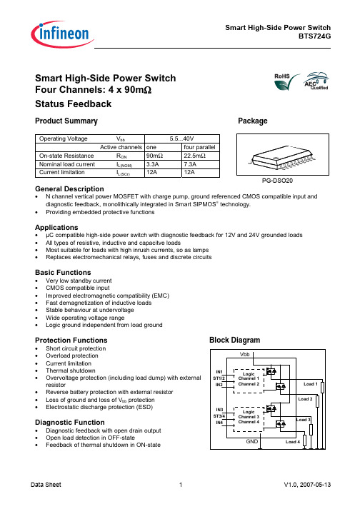
BTS724G中文资料
关于BTS的介绍all
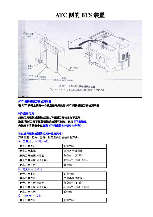
ATC侧的BTS装置ATC侧的破损刀具检测功能在ATC手臂上装有一个感应器用来执行ATC侧的破损刀具检测功能。
BTS-应用刀具如果刀具破损或磨损达到以下值则刀具状态为不正常。
注意;有时刀具下部的破损试检测不到的。
参见BTS的设定为提高BTS精度参见提高BTS精度的M代码(M435)可以进行破损检测的刀具种类及尺寸:刀具类型:钻头、丝锥、铰刀及类似圆柱状的刀具。
注意:刀具刚性参照为近似于φ0.5,长10mm的刀具。
当刀具更长但具有如上尺寸的同样刚性时也可以使用。
注意:在一些铣刀刀具中,由于破损的刀片并没有改变刀具长度,因此无法检测到这些破损刀具。
BTS的设定ATC侧的BTS设定在TOOL DETAIL显示屏的BTS页面上。
BTS的设定步骤:1)显示器初始的操作屏(CUSTOM键下主屏幕)。
2)按下[TOOL DETAIL]软键显示TOOL DETAIL屏幕。
3)按下[DISPLY SHIFT]软键数次,直到显示BTS的设定页面。
4)按下[INPUT/DISPLY]软键,开启BTS功能。
5)移动光标到需要进行BTS检查的刀具刀号上,再移动光标到BT上。
6)按下[BTS ON/OFF]软键一次以在BT列表里显示[ON]来激活BTS功能。
如果[BTS ON/OFF]键被按下超过一次,BTS功能会被关闭。
7)确保在刀具LENGTH列表里输入刀具的实际长度值。
BTS的数据设定屏幕A:一个BTS数据设定的显示屏:BT:此列显示的是ATC侧的BTS检查是否需要进行,只有当状态为ON时BTS检查才会执行。
LENGTH:此列中输入刀具的实际长度,BTS检查是以此数据作为检查参考的(参考刀具长度数据输入错误)。
ALARM:当刀具破损(刀具使用后测出的长度小于使用之前),“BT”字样会在此列显示(参考清除报警的步骤)。
如果一把刀具破损,会产生报警停机。
清除报警的方法参考后面的刀具长度输入错误(参考刀具长度数据输入错误)。
LTC4413中文资料

DESCRIPTIO
The LTC®4413 contains two monolithic ideal diodes, each capable of supplying up to 2.6A from input voltages between 2.5V and 5.5V. Each ideal diode uses a 100mΩ P-channel MOSFET that independently connects INA to OUTA and INB to OUTB. During normal forward operation the voltage drop across each of these diodes is regulated to as low as 28mV. Quiescent current is less than 40µA for diode currents up to 1A. If either of the output voltages exceeds its respective input voltages, that MOSFET is turned off and less than 1µA of reverse current will flow from OUT to IN. Maximum forward current in each MOSFET is limited to a constant 2.6A and internal thermal limiting circuits protect the part during fault conditions.
BTS443P中文资料
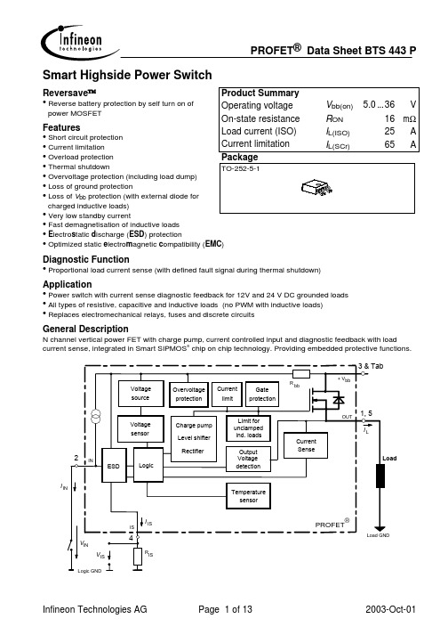
Diagnostic Function Application
• Proportional load current sense (with defined fault signal during thermal shutdown) • Power switch with current sense diagnostic feedback for 12V and 24 V DC grounded loads • All types of resistive, capacitive and inductive loads (no PWM with inductive loads) • Replaces electromechanical relays, fuses and discrete circuits
• Short circuit protection • Current limitation • Overload protection • Thermal shutdown TO-252-5-1 • Overvoltage protection (including load dump) • Loss of ground protection • Loss of Vbb protection (with external diode for charged inductive loads) • Very low standby current • Fast demagnetisation of inductive loads • Electrostatic discharge (ESD) protection • Optimized static electromagnetic compatibility (EMC)
PLM20K44产品说明书

2012-12-21
U516
x
U510
x
U512, , U514, U505
x
U506
x
U508, U509
x
U507
x
U900
x
U902
x
D3, D304, D307, D504
x
D303, D305
27V.25W5%SOT-23 COAEXPFC52-A01 COAEXPFC70-A01 COAEXPFC70-A03
COCIPI4X2-A01
COSP05FB 6R8.33W5%1206 2R7.33W5%1206 10K.125W1%0805
22n630VMKP7.5 T50WFETD29 T16A400-5x20AL T3A15400-5x20
Q3, Q7, Q307, Q308, Q508 Q4, Q5, Q8, Q9, Q400, Q401, Q403, Q507, Q404, Q12
Q408
Q11 Q10, Q500 Q509
Q505 U300, U401
U407, U408, U504
Ic Operational Amplifier Lm833 SOIC Narrow body Ic dual gate driver FAN3224CMX SOIC-8 Pulse Width Modulator PFC type 1 rev.03a Final Assembly 01
Ic Comparator Lm339D
Ic Digital Isolator SI8441-C Ic Inverting Scmitt trigger 74AHC1G14 SOT353-1 Diode Signal Bas21 SOT-23 Diode Power 1n4006 Diode Zener 6V2 .225W 2% SOT-23
BTS724G中文资料

9EE $FWLYH FKDQQHOV RQH
9 IRXU SDUDOOHO
P-DSO-20
2QVWDWH 5HVLVWDQFH 1RPLQDO ORDG FXUUHQW
521 ,/ 120
PΩ $
PΩ $
&XUUHQW OLPLWDWLRQ
,/ 6&U
Pin Definitions and Functions
Pin 1,10, 11,12, 15,16, 19,20 3 5 7 9 18 17 14 13 4 8 2 6
Symbol Vbb
IN1 IN2 IN3 IN4 OUT1 OUT2 OUT3 OUT4 ST1/2 ST3/4 GND1/2 GND3/4
IL = 3.3 A, EAS = 120 mJ, 0 Ω
one channel:
IL = 4.7 A, EAS = 140 mJ, 0 Ω two parallel channels:
IL = 7.3 A, EAS = 160 mJ, 0 Ω four parallel channels:
Electrostatic discharge capability (ESD)
Parameter and Conditions
Symbol
Thermal resistance junction - soldering point6)7)
junction – ambient6) @ 6 cm2 cooling area
IN:
(Human Body Model)
ST:
out to all other pins shorted:
acc. MIL-STD883D, method 3015.7 and ESD assn. std. S5.1-1993
NTS-711通用保护测控装置说明书-V1.00
LTC4411ES5#TRMPBF;LTC4411ES5#TR;LTC4411ES5#TRPBF;LTC4411ES5#TRM;中文规格书,Datasheet资料

IFWD
Figure 1. Automatic Switchover of Load Between a Battery and a Wall Adapter
VFWD
/
U
LTC4411 vs Schottky Diode Forward Voltage Characteristics
LTC4411 2.6A Low Loss Ideal Diode in ThinSOTTM
FEATURES
■ ■ ■ ■ ■ ■ ■ ■ ■ ■ ■ ■
ቤተ መጻሕፍቲ ባይዱ
DESCRIPTIO
Low Loss Replacement for PowerPathTM OR’ing Diodes Small Regulated Forward Voltage (28mV) 2.6A Maximum Forward Current Low Forward ON Resistance (140mΩ Max) Low Reverse Leakage Current (<1µA) 2.6V to 5.5V Operating Range Internal Current Limit Protection Internal Thermal Protection No External Active Components Pin-Compatible Monolithic Replacement for the LTC4412 Low Quiescent Current (40µA) Low-Profile (1mm) 5-lead SOT-23 Package
●
ELECTRICAL CHARACTERISTICS
STAT Output IS(SNK) IS(OFF) tS(ON) tS(OFF) CTL Input VTH VHYST ICTL IOC IQOC
石冢ntc温度传感器
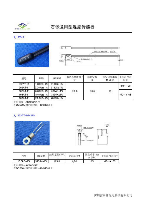
EC2F202A2-71048 2kΩ±1% 3182K±1%
EC2F502A2-40103 5kΩ±1% 3324K±1%
EC2F103A2-40113 10kΩ±1% 3435K±1%
EC2F203A2-70030 20kΩ±1% 4013K±1%
EC2F503A2-70456 50kΩ±1% 4060K±1%
EC2F104A2-60109 100kΩ±1% 4665K±1%
散热系数...约3.0MW /℃ 热时常数...约80秒 介电强度···AC2400V1秒 在DC500V的绝缘电阻···100MΩ以上
成型树脂颜色 水色 赤色 灰色 黒色 青色 白色 緑色
工作温度范围 ℃
-40~+90
-40~+110
R25
B25/85
散热系数mW / ℃
100.0kΩ±1% 4261K±1%
約4.0
介电强度···AC600V1秒
在DC500V的绝缘电阻···100MΩ以上
ቤተ መጻሕፍቲ ባይዱ
熱時定数 s
約4.0
额定功率mW at 25℃
20
工作温度范围 ℃
-30~+90
深圳富泰林光电科技有限公司
深圳富泰林光电科技有限公司
7、EP1C212C0-ASSY-3
R35
B0/25
散热系数mW / ℃
1.433kΩ±2% 3400K±2%
約5.0
介电强度···AC1800V1秒 在DC500V的绝缘电阻···100MΩ以上
熱時定数 s
約10
8、ED5F103A2-ASSY-4
额定功率mW at 25℃
約3.0
介电强度···AC600V1秒 在DC500V的绝缘电阻···100MΩ以上
LF441CN中文资料

2
元器件交易网
LF441C LF442C LF444C
AC ELECTRICAL CHARACTERISTICS (VCC = +15 V, VEE = –15 V, TA = +25°C, unless otherwise noted.)
Output 4 Inputs 4 VEE Inputs 3 Output 3
+ + 2 3 1 4
+ + -
13 12 11 10 9 8
(Quad, Top View)
© Semiconductor Components Industries, LLC, 2002
1
March, 2002 – Rev. 1
Publication Order Number: LF441C/D
元器件交易网
LF441C LF442C LF444C
MAXIMUM RATINGS
Rating Supply Voltage (from VCC to VEE) Input Differential Voltage Range (Note 1) Input Voltage Range (Notes 1 and 2) Output Short Circuit Duration (Note 3) Operating Junction Temperature (Note 3) Storage Temperature Range Symbol VS VIDR VIR tSC TJ Tstg Value +36 ±30 ±15 Indefinite +150 –60 to +150 Unit V V V sec °C °C
Figure 3. Input Bias Current versus Temperature
ADG441BR中文资料

85 110 45 60 30 1 6 60 100 4 4 16
170 80
85 110 45 60 30 1 6 60 100 4 4 16
170 80
RL = 1 kΩ, CL = 35 pF; VS = ± 10 V; Test Circuit 4 RL = 1 kΩ, CL = 35 pF; VS = ± 10 V; Test Circuit 4 RL = 1 kΩ, CL = 35 pF; VS = 0 V, RS = 0 Ω, CL= 1 nF; VDD = +15 V, VSS = –15 V; Test Circuit 5 RL = 50 Ω, CL = 5 pF; f = 1 MHz; Test Circuit 6 RL = 50 Ω, CL = 5 pF; f = 1 MHz; Test Circuit 7 f = 1 MHz f = 1 MHz f = 1 MHz VDD = +16.5 V, VSS = –16.5 V Digital Inputs = 0 V or 5 V
± 0.01 ± 0.5 ± 0.01 ± 0.5 ± 0.08 ± 0.5
±3 ±3 ±3 2.4 0.8 ± 0.00001 ± 0.5
± 0.01 ± 0.5 ± 0.01 ± 0.5 ± 0.08 ± 0.5
± 20 ± 20 ± 40 2.4 0.8 ± 0.00001 ± 0.5
VIN = VINL or VINH
1. Extended Signal Range The ADG441/ADG442/ADG444 are fabricated on an enhanced LC2MOS, trench-isolated process, giving an increased signal range that extends to the supply rails. 2. Low Power Dissipation 3. Low RON 4. Trench Isolation Guards Against Latch Up A dielectric trench separates the P and N channel transistors thereby preventing latch up even under severe overvoltage conditions. 5. Break-Before-Make Switching This prevents channel shorting when the switches are configured as a multiplexer. 6. Single Supply Operation For applications where the analog signal is unipolar, the ADG441/ADG442/ADG444 can be operated from a single rail power supply. The parts are fully specified with a single +12 V power supply.
LTC4411资料

ELECTRICAL CHARACTERISTICS
MIN 2.6
TYP 40
MAX 5.5
VIN = 3.6V, ILOAD = 100mA VIN = 3.6V VOUT = 3.7V VIN = 3.6V VOUT = 3.7V VIN = 0V, VOUT = 5.5V VIN = 3.6V VIN = 3.6V VIN = 3.6V, 80µA < ILOAD < 1A VIN = 3.6V, ILOAD = 1000mA VIN Rising, 0°C < TA < 85°C VIN Rising VIN Falling VIN = 3.6V, VOUT > VIN + VRTO, VCTL > VTH + VHYST VIN = 3.6V, VOUT < VIN – VFWD, VCTL < VTH – VHYST
元器件交易网
LTC4411 2.6A Low Loss Ideal Diode in ThinSOTTM
FEATURES
s s s s s s s s s s
DESCRIPTIO
s s
Low Loss Replacement for PowerPathTM OR’ing Diodes Small Regulated Forward Voltage (28mV Min) 2.6A Maximum Forward Current Low Forward ON Resistance (140mΩ Max) Low Reverse Leakage Current (<1µA) 2.6V to 5.5V Operating Range Internal Current Limit Protection Internal Thermal Protection No External Active Components Pin-Compatible Low-Power Replacement for LTC4412 Low Quiescent Current (40µA typical) Low-profile (1mm) 5-lead SOT-23 Package
太赫兹透镜材料

太赫兹透镜材料
- TPX透镜:近两年,维尔克斯光电陆续推出了不同型号的太赫兹透镜,其中标准化的透镜达23种,主要材质为TPX透镜。
- Ⅲ-Ⅴ族半导体材料:基于Ⅲ-Ⅴ族半导体材料锑化铟(InSb),设计性能优异的单元结构。
随后,采用几何相位和传输相位相结合的方式,设计超透镜单元结构的排布方式与空间取向,采用单层超透镜实现了太赫兹波的宽频带聚焦,有效消除了色差现象。
- 石英晶体:在太赫兹波段,石英晶体是一种常用的材料,能作为原材料生产太赫兹透镜、石英棱镜、太赫兹窗镜、石英波片等。
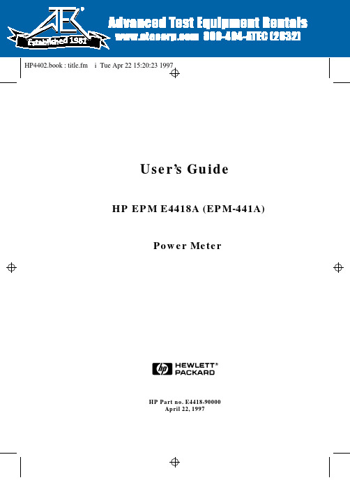
HP EPM-441A 用户指南说明书
5SpecificationsSpecifications Introduction5-2HP EPM-441A User’s GuideIntroductionThis chapter details the power meter’s specifications and supplemental characteristics.Specifications describe the warranted performance and apply after a 30minute warm-up. These specifications are valid over the power meter’s operating and environmental range unless otherwise stated and after performing a zero and calibration.Supplemental characteristics, which are shown in italics, are intended to provide information useful in applying the power meter by giving typical,but nonwarranted performance parameters. These characteristics are shown in italics or denoted as “typical”, “nominal” or “approximate”.For information on measurement uncertainty calculations, refer toHP Application Note 64-1A, “Fundamentals of RF and Microwave Power Measurements”, Literature Number 5965-6630.Specifications Power Meter SpecificationsHP EPM-441A User’s Guide 5-3Power Meter SpecificationsMeterFrequency Range100kHz to 50GHz and 75GHz to 110GHz, power sensor dependent Power Range-70dBm to +44dBm (100pW to 25W), power sensor dependent Power SensorsCompatible with all HP 8480 series power sensors and HP ECP-series power sensors.Single Sensor Dynamic Range90dB maximum (HP ECP-series power sensors)50dB maximum (HP 8480 series power sensors)Display UnitsAbsolute: Watts or dBmRelative:Percent or dBDisplay ResolutionSelectable resolution of:1.0, 0.1, 0.01 and 0.001dB in logarithmic mode, or1, 2, 3 and 4 significant digits in linear modeDefault Resolution0.01dB in logarithmic mode3 digits in linear modeSpecifications Power Meter Specifications5-4HP EPM-441A User’s GuideAccuracyInstrumentationAbsolute:±0.02dB (Logarithmic) or ±0.5% (Linear). (Refer to the power sensor linearity specification in your power sensor manual to assess overall system accuracy .)Relative:±0.04dB (Logarithmic) or ±1.0% (Linear). (Refer to the power sensor linearity specification in your power sensor manual to assess overall system accuracy .)Zero Set (digital settability of zero): Power sensor dependent (refer to Table 5-1). For HP ECP-series power sensors, this specification applies when zeroing is performed with the sensor input disconnected from the POWER REF .Table 5-1: Zero Set Specifications Power Sensor Zero SetHP 8481A ±50nWHP 8481B ±50µWHP 8481D ±20pWHP 8481H ±5µWHP 8482A ±50nWHP 8482B ±50µWHP 8482H ±5µWHP 8483A ±50nWHP 8485A ±50nWHP 8485D ±20pWHP R8486A ±50nWHP R8486D ±30pWHP Q8486A ±50nWHP Q8486D ±30pWHP W8486A ±200nWHP 8487A ±50nWHP 8487D ±20pWHP ECP-E18A ±50pWHP ECP-E26A ±50pWSpecifications Power Meter SpecificationsHP EPM-441A User’s Guide 5-5Power ReferencePower Output1.00mW (0.0dBm). Factory set to ±0.7% traceable to the US National Institute of Standards and Technology .Accuracy±1.2% worst case (±0.9% rss) for one year.Specifications Power Meter Supplemental Characteristics5-6HP EPM-441A User’s GuidePower Meter Supplemental Characteristics Power ReferenceFrequency50MHz nominalSWR1.05 maximumConnectorType N (f), 50ΩMeasurement SpeedOver the HP-IB, three measurement speed modes are available as shown,along with the typical maximum measurement speed for each mode:•Normal: 20 readings/second•x 2: 40 readings/second•Fast: 200 readings/second, for HP ECP-series power sensors only Maximum measurement speed is obtained using binary output in free run trigger mode.Specifications Power Meter Supplemental CharacteristicsHP EPM-441A User’s Guide 5-7Zero Drift of SensorsPower sensor dependent (refer to Table 5-3).Measurement NoisePower sensor dependent (refer to Table 5-2 and Table 5-3).Averaging effects on measurement noise. Averaging over 1 to 1024readings is available for reducing noise. Table 5-3 provides themeasurement noise for a particular power sensor with the number of averages set to 16 for normal mode and 32 for x2 mode. Use the “Noise Multiplier” for the appropriate mode (normal or x2) and number of averages to determine the total measurement noise value.For example, for an HP 8481D power sensor in normal mode with the number of averages set to 4, the measurement noise is equal to:(<45pW x 2.75) = <124pWTable 5-2: Noise Multiplier Number of Averages12481632641282565121024Noise Multiplier (Normal Mode)5.5 3.89 2.75 1.94 1.00.850.610.490.340.240.17Noise Multiplier (x2 mode)6.5 4.6 3.25 2.3 1.18 1.00.720.570.410.290.2Specifications Power Meter Supplemental Characteristics5-8HP EPM-441A User’s GuideTable 5-3: Power Sensor Specifications1. Within 1 hour after zero set, at a constant temperature, after a 24hour warm-up of the power meter.2. The number of averages at 16 (for normal mode) and 32 (for x2 mode),at a constant temperature, measured over a 1 minute interval and 2standard deviations. For HP ECP-series power sensors themeasurement noise is measured within the low range. Refer to the relevant power sensor manual for further information.Power Sensor Zero Drift 1Measurement Noise 2HP 8481A <±10nW <110nWHP 8481B <±10µW <110µWHP 8481D <±4pW <45pWHP 8481H <±1µW <10µWHP 8482A <±10nW <110nWHP 8482B <±10µW <110µWHP 8482H <±1µW <10µWHP 8483A <±10nW <110nWHP 8485A <±10nW <110nWHP 8485D <±4pW <45pWHP R8486A <±10nW <110nWHP R8486D <±6pW <65pWHP Q8486A <±10nW <110nWHP Q8486D <±6pW <65pWHP W8486A <±40nW <450nWHP 8487A <±10nW <110nWHP 8487D <±4pW <45pWHP ECP-E18A <± 15pW <70pWHP ECP-E26A <± 15pW <70pWSpecifications Power Meter Supplemental CharacteristicsHP EPM-441A User’s Guide 5-9Settling Time0 to 99% settled readings over the HP-IB.For HP 8480 series power sensorsManual filter , 10dB decreasing power step:Table 5-4: Settling TimeAuto filter , default resolution, 10dB decreasing power step,normal and x 2 speed modes:Number of Averages12481632641282565121024Settling Time (s)(Normal Mode)0.150.20.30.5 1.1 1.9 3.4 6.6132757Response Time (s)(x2 mode)0.150.180.220.350.55 1.1 1.9 3.5 6.914.533150 ms 6.6 s 500ms 200 ms Power 10 dB 10 dB 10 dB 20 dB Maximum dBm Minimum dBm Settling Times SensorDynamic Range150 ms 3.5s 350ms 180ms Power 10 dB 10 dB 10 dB20 dB Maximum dBm Minimum dBmSettling Times SensorDynamic RangeNormal Mode x2 Mode Typical TypicalSpecifications Power Meter Supplemental Characteristics5-10HP EPM-441A User’s GuideFor HP ECP-series power sensorsIn FAST mode, within the range -50dBm to +17dBm, for a 10dB decreasing power step, the settling time is 10ms 1.1When a decreasing power step crosses the power sensor’s auto-range switch point, add 25 ms. Refer to the relevant power sensor manual for further information.For HP ECP-series power sensors in normal and x 2 speed modes, manual filter , 10dB decreasing power step:Table 5-5: Settling Time Number of Averages12481632641282565121024Settling Time (s)(Normal Mode)0.070.120.210.41 1.8 3.3 6.5132757Response Time (s)(x2 mode)0.040.070.120.210.41 1.8 3.4 6.814.232Specifications Power Meter Supplemental CharacteristicsHP EPM-441A User’s Guide 5-11Auto filter , default resolution, 10dB decreasing power step,normal and x 2 speed modes:10 dB10 dB10 dB60 dBMaximum dBmMinimum dBmPowerSensor 40 ms 3.4 s 210ms 70 ms Settling Times Typical Dynamic Range10 dB 10 dB10 dB 60 dB Maximum dBm Minimum dBmPower Sensor 70 ms 6.5 s 400ms 120 ms Settling Times Typical Dynamic Range Normal Mode x2 ModeSpecifications Power Meter Supplemental Characteristics5-12HP EPM-441A User’s GuidePower Sensor SpecificationsDefinitionsZero SetIn any power measurement, the power meter must initially be set to zero with no power applied to the power sensor. Zero setting is accomplished within the power meter by digitally correcting for residual offsets.Zero DriftThis parameter is also called long term stability and is the change in the power meter indication over a long time (usually one hour) for a constant input power at a constant temperature, after a defined warm-up interval.Measurement NoiseThis parameter is also known as short term stability and is specified as the change in the power meter indication over a short time interval (usually one minute) for a constant input power at a constant temperature.Specifications General CharacteristicsHP EPM-441A User’s Guide 5-13General CharacteristicsRear Panel ConnectorsRecorder OutputAnalog 0-1 Volt, 1k Ω output impedance, BNC connectorHP-IBAllows communication with an external controller .GroundBinding post, accepts 4mm plug or bare-wire connectionLine Power•Input V oltage Range: 85 to 264Vac, automatic selection •Input Frequency Range: 47 to 63Hz•Power Requirement: approximately 50VA (14 Watts)Specifications Environmental Characteristics5-14HP EPM-441A User’s GuideEnvironmental CharacteristicsGeneral ConditionsComplies with the requirements of the EMC Directive 89/336/EEC. This includes Generic Immunity Standard EN 50082-1: 1992 and Radiated Interference Standard EN 55011:1991/CISPR11:1990, Group 1 - Class A.Operating EnvironmentTemperature0ºC to 55ºCMaximum Humidity95% at 40ºC (non-condensing)Minimum Humidity15% at 40ºC (non-condensing)Maximum Altitude3,000 meters (9,840 feet)LocationFor use indoors.Storage ConditionsStorage Temperature-20ºC to +70ºCNon-Operating Maximum Humidity90% at 65ºC (non-condensing)Non-Operating Maximum Altitude15,240 meters (50,000 feet)Specifications GeneralHP EPM-441A User’s Guide 5-15GeneralDimensionsThe following dimensions exclude front and rear panel protrusions:212.6mm W x 88.5mm H x 348.3mm D (8.5 in x 3.5 in x 13.7 in)WeightNet4.0Kg (8.8lb)Shipping7.9Kg (17.4lb)SafetyConforms to the following Product Specifications:•EN61010-1: 1993/IEC 1010-1:1990+A1/CSA C22.2 No.1010-1:1993•EN60825-1: 1994/IEC 825-1: 1993 Class 1•Low Voltage Directive 72/23/EECRemote ProgrammingInterfaceHP-IB interface operates to IEEE 488.2.Command LanguageSCPI standard interface commands. HP 437B code compatible.HP-IB CompatibilitySH1, AH1, T6, TE0, L4, LE0, SR1, RL1, PP1, DC1, DT1, C0Specifications General5-16HP EPM-441A User’s Guide Non-Volatile MemoryBatteryLithium Polycarbon Monoflouride, approximate lifetime 5 years at 25ºC.。
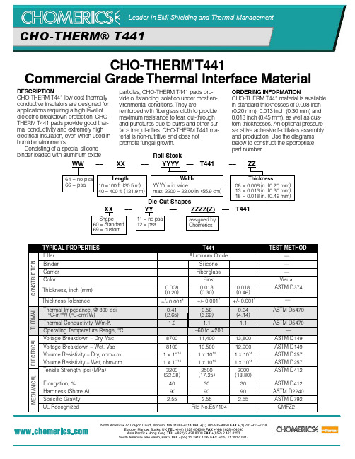
CHO-THERM T441商业级热接材料说明书
CHO-THERM ®T441Commercial Grade Thermal Interface MaterialDESCRIPTIONCHO-THERM T441 low-cost thermally conductive insulators are designed for applications requiring a high level of dielectric breakdown protection. CHO-THERM T441 pads provide good ther-mal conductivity and extremely high electrical insulation, even when used in humid environments.Consisting of a special silicone binder loaded with aluminum oxideparticles, CHO-THERM T441 pads pro-vide outstanding isolation under most en-vironmental conditions. They arereinforced with fiberglass cloth to provide maximum resistance to tear , cut-throughand punctures due to burrs and other sur-face irregularities. CHO-THERM T441 ma-terial is non-nutritive and does not promote fungal growth.Die-Cut ShapesXX –– YY–– ZZZZ(Z) –– T441WW –– XX ––YYYY –– T441–– ZZRoll Stock64 = no psa 66 = psaLength10 =100 ft. (30.5 m)40 = 400 ft. (121.9 m)WidthYY .YY = in. widemax. 2200 = 22.00 in. (55.9 cm)Thickness08 = 0.008 in. (0.20 mm)13 = 0.013 in. (0.30 mm)18 = 0.018 in. (0.46 mm)Shape60 = Standard 69 = custom11 = no psa 12 = psaassigned by ChomericsORDERING INFORMA TIONCHO-THERM T441 material is available in standard thicknesses of 0.008 inch (0.20 mm), 0.013 inch (0.30 mm) and 0.018 inch (0.45 mm), as well as cus-tom thicknesses. An optional pressure-sensitive adhesive facilitates assembly and production. Use the diagrams below to construct the appropriate part number .CHO-THERM® T441North America• 77 Dragon Court, Woburn, MA 01888-4014 TEL +(1) 781-935-4850 FAX +(1) 781-933-4318Europe• Marlow, Bucks, UK TEL +(44) 1628 404000 FAX +(44) 1628 404090 Asia Pacific • Hong Kong TEL +(852) 2 428 8008 FAX +(852) 2 423 8253South America• São Paulo, Brazil TEL +(55) 11 3917 1099 FAX +(55) 11 3917 0817CHO-THERM® T441。
cx441p原理
cx441p原理CX441P是一款高性能的数字信号处理器(DSP),广泛应用于各种实时信号处理领域。
本篇文章将详细阐述CX441P 的原理及其主要特性,并探讨其在实际应用中的优势。
一、结构与原理CX441P基于先进的哈佛结构,具有独立的数据总线和程序总线,从而实现了高速的数据读写和程序执行。
其内部包含多个功能强大的处理单元,如乘法器、累加器、移位器等,以满足实时信号处理的需求。
1.乘法器:CX441P内置了两组乘法器,可以并行处理两个16位或32位定点数的乘法运算,大大提高了处理速度。
2.累加器:CX441P拥有多个累加器,可实现高速的数据加法运算。
在执行循环累加操作时,可以显著减少外部存储器的访问次数,提高程序执行效率。
3.移位器:CX441P内置了多种移位器,可以实现数据的左移、右移和循环移位等操作。
在信号处理过程中,能够灵活地调整数据位宽,满足不同应用场景的需求。
4.程序控制:CX441P采用了先进的流水线技术,实现了高效的程序执行。
通过硬件循环、条件跳转等功能,可以根据实际需求灵活地控制程序流程。
5.存储器:CX441P支持多种存储器接口,如SDRAM、FLASH等。
其内部集成了大容量的寄存器组,可以存储中间计算结果,降低外部存储器的访问压力。
二、主要特性1. 高性能:CX441P具有较高的运算速度,可以满足实时信号处理的要求。
在执行复杂数学运算时,其性能优势尤为明显。
2.低功耗:CX441P采用了先进的低功耗技术,降低了功耗,提高了电池续航能力。
3.紧凑型封装:CX441P采用了紧凑型封装,减小了体积,方便集成到各种电子设备中。
4.丰富的外设接口:CX441P提供了丰富的外设接口,如UART、SPI、I2C等,方便与各类传感器、通信模块等外部设备连接。
5.软件兼容性:CX441P支持多种编程语言,如C、汇编等,便于开发者进行程序设计和优化。
三、应用领域CX441P凭借其高性能、低功耗、丰富的接口等优势,广泛应用于以下领域:1.通信:CX441P可以应用于无线通信、光纤通信等场景,实现信号处理、调制解调等功能。
- 1、下载文档前请自行甄别文档内容的完整性,平台不提供额外的编辑、内容补充、找答案等附加服务。
- 2、"仅部分预览"的文档,不可在线预览部分如存在完整性等问题,可反馈申请退款(可完整预览的文档不适用该条件!)。
- 3、如文档侵犯您的权益,请联系客服反馈,我们会尽快为您处理(人工客服工作时间:9:00-18:30)。
Standby current (pin 3) 8) VIN=0 see diagram page 9
Tj =-40°C Tj =+25°C Tj =+105°C6) Tj =+150°C Tj =-40°C: Tj =+25...+150°C: Tj=-40...+25°C: Tj=+105°C6): Tj=+150°C:
• Providing embedded protective functions.
Application
• µC compatible power switch for 5V, 12 V and 24 V DC applications • All types of resistive, inductive and capacitve loads • Most suitable for loads with high inrush currents, so as lamps • Replaces electromechanical relays, fuses and discrete circuits
RON
IL(ISO) IL(GNDhigh)
ton toff dV /dton -dV/dtoff
-- 15 20 mΩ 28 37
17 21
-- A
--
--
2 mA
40 90 200 µs 40 110 250
0.1
--
1 V/µs
0.1
--
1 V/µs
Operating Parameters
Operating voltage
Protection Functions
• Short circuit protection
Vbb
• Current limitation
• Overload protection
• Thermal shutdown
• Overvoltage protection (including load dump) with external
Vbb Vbb
VLoad dump3)
IL Tj Tstg Ptot
ZL VESD
VIN IIN
Thermal resistance
chip - case: RthJC junction - ambient (free air): RthJA
SMD version, device on pcb5):
see diagram page 9
Nominal load current (pin 3 to 5)
‘ISO 10483-1, 6.7:VON=0.5V, TC=85°C
Output current (pin 5) while GND disconnected or GND pulled up6), Vbb=30 V, VIN= 0,
Off-State output current (included in Ibb(off)) VIN=0
Operating current (Pin 1)9), VIN=5 V,
Vbb(on)
Vbb(AZ) Ibb(off) IL(off) IGND
4.75
--
4.75
--
4.75
--
5.0
--
41
IN
with
protection
functions
OUT
PROFET GND
Load
Infineon Technologies AG
1 of 11
2003-Oct-01
元器件交易网
Functional diagram
BTS 441 T
overvoltage protection
4) EAS is the maximum ctive switch off energy
5) Device on 50mm*50mm*1.5mm epoxy PCB FR4 with 6cm2 (one layer, 70µm thick) copper area for Vbb connection. PCB is vertical without blown air.
see diagram page 7
Turn-on time
Turn-off time RL = 12 Ω,
IN
to 90% VOUT:
IN
to 10% VOUT:
Slew rate on
10 to 30% VOUT, RL = 12 Ω,
Slew rate off 70 to 40% VOUT, RL = 12 Ω,
Load current (Short-circuit current, see page 5)
Operating temperature range
Storage temperature range
Power dissipation (DC) ; TC≤25°C
Maximal switchable inductance, single pulse
Basic Funktions
• Very low standby current • Optimized static electromagnetic compatibility (EMC) • µC and CMOS compatible • Fast demagnetization of inductive loads • Stable behaviour at undervoltage
Vbb = 12V, Tj,start = 150°C, TC = 150°C const. (see diagram, p.8) IL(ISO) = 21 A, RL= 0 Ω: E4)AS=0.7J:
Electrostatic discharge capability (ESD)
IN:
(Human Body Model) Out to all other pins shorted:
Infineon Technologies AG
3
2003-Oct-01
元器件交易网
BTS 441 T
Electrical Characteristics
Parameter and Conditions at Tj =-40...+150°C, Vbb = 12 V unless otherwise specified
4
N.C.
Not connected
5
OUT
Tab
Vbb
Output to the load
Positive power supply voltage The tab is shorted to pin 3
Pin configuration (top view)
Tab = VBB
1 2 (3) 4 5
GND IN
NC OUT
Infineon Technologies AG
2
2003-Oct-01
元器件交易网
Maximum Ratings at Tj = 25 °C unless otherwise specified
Parameter
Symbol
Supply voltage (overvoltage protection see page 4)
GND-resistor
Logic
• Reverse battery protection with external GND-resistor • Loss of ground and loss of Vbb protection • Electrostatic discharge (ESD) protection
Pin Symbol
Function
1
GND
Logic ground
2
IN
Input, activates the power switch in case of logical high signal
3
Vbb
Positive power supply voltage The tab is shorted to pin 3
resistor in the GND connection. A resistor for the protection of the input is integrated.
2) RI = internal resistance of the load dump test pulse generator 3) VLoad dump is setup without the DUT connected to the generator per ISO 7637-1 and DIN 40839
RON Vbb(on) IL(ISO) IL(lim)
20mΩ 4.75 ... 41V 21A 65A
BTS 441 T
Package
TO-220-5-11 TO-263-5-2 TO-220-5-12
Standard
SMD
Straight
General Description
• N channel vertical power FET with charge pump, ground referenced CMOS compatible input, monolithically integrated in Smart SIPMOS® technology.
Symbol
Values
Unit
min typ max
Load Switching Capabilities and Characteristics
