UA9638
地面卫星接收器密码解锁大全
地面卫星接收器密码解锁大全地面卫星接收器密码解锁大全引用地面卫星接收器密码机解集以及修改步骤大全!最新科技!(声明:此信息供给技术交流不涉及涉密性质。
信源来至互联网)66种134款卫星电视接收机密码进入方法一、皇视1、皇视2080:在“转发器设定”时按5160、1698、156988。
2、皇视2080A型冲击波机(V:);在开机状态下用遥控器按“菜单”键→电视屏显皇视主菜单→键入“530478”,电视机屏显“系统信息,数据存储中……”,待显示消失,在皇视主菜单中出现“自动搜索”,机内电视节目自动恢复为工厂设置。
此时选中“自动搜索”,设置相应参数,即可进行盲扫。
3、皇视HSR-2080A:调出主菜单→进入“转发器设置”一项,直接用遥控器按“1698”→画面出现“系统更新”字样,随后在主菜单“节目编辑”的下一栏出现“自动搜索”,进入该栏,按照相应的参数设置,再按“确认”键即可。
4、皇视HSR-2080C:将光标移至“转发器设定”,用遥控器数字键输入“1698”或“5168”即可。
5、皇视2080/C:菜单→皇视主菜单→转发器设定→5168或235523即可。
6、皇视2080系列设置方法:打开主菜单直接输入“5168”即可恢复。
7、皇视免费机的方法密码530478。
二、东仕8、东仕:(1)在恢复出厂时按“1270”。
(2)恢复出厂确定时按左键→“喜爱”键。
(3)各版本9画面的打开方法:版:右键→ 确认键。
版:改名键→左键→确认键。
版:右键→左键→改名键→确认键。
9、东仕2000Q开启盲扫和9画面设置:按菜单→系统设置→恢复出厂设置→确认恢复(先不要按确认),按音量右键,然后按确认键恢复出厂状态,这时机器恢复到了出厂状态,9画面功能开启:进行第二次的按菜单→系统设置→恢复出厂设置→确认恢复(先不要按确认),按喜爱键,机器再一次恢复到出厂状态,9画面和盲扫都打开了。
注意:使用9画面,直接按“0”键就可以了;“盲扫”请使用菜单→节目设置→单星搜索2。
浅谈数字音频接口
浅谈数字音频接口作者:Purer(1)关于数字音频接口的基本知识“数字音频接口”是用来定义两个数字音频设备之间的数字接口协议的界标准格式,它分为家用的.专业的,电脑的三种格式:①家用的标准:S/PDIF(索尼/飞利浦数字接口格式),EIAJ CP-340 IEC-958 同轴或光缆,属不平衡式。
其标准的输出电平是0.5Vpp(发送器负载75Ω),输入和输出阻抗为75Ω(0.7-3MHz频宽)。
常用的有光纤.RCA和BNC。
我们常见的是RCA插头作同轴输出,但是用RCA作同轴输出是个错误的做法,正确的做法是用BNC作同轴输出,因为BNC头的阻抗是75Ω,刚刚好适合S/PDIF的格式标准,但由于历史的原因,在一般的家用机上用的是RCA作同轴输出。
②专业的标准:AES/EBU(美国音频工程协会/欧洲广播联盟数字格式),AES3-1992,平衡XLR电缆,属平衡式结构。
输出电压是2.7Vpp(发送器负载110Ω),输入和输出阻抗为110Ω(0.1-6MHz频宽)。
③电脑的标准:AT﹠T(美国电话电报公司)。
(2)关于各种接口的优点与缺点从单纯的技术的角度来说,光纤电缆是导体传输速度最快的,是一个极好的数据传输的接线,但是由于它需要光纤发射口和接收口,问题就是出在这里,光纤发射口和接收口的光电转换需要用光电二极管,由于光纤和光电二极管不可能有紧密的接触,从而产生数字抖动(Jitter)类的失真而这个失真是叠加的,因它有两个口(发射口和接收口)。
再加上在光电转换过程中的失真,使它是几种数字电缆中最差的。
但奇怪的是日本的机十分喜欢用光纤电缆,可能生产成本比同轴便宜。
同轴电缆是欧洲机喜欢用的,凡是有数字输出的都有同轴输出。
但从我的实际上的经验发现其数字接口的重要性并不亚于光纤发射口和接收口。
同轴输入和输出的传输方法有几种:(1)用74HCU04作缓冲.放大和整形在输入和输出一样。
(2)用74HCU04作缓冲.放大和整形在输入和输出一样,但在输入和输出端加上脉冲变压器,防止数字音源通过共模噪声抑的屏蔽线输入机内,输入和输出配接脉冲变压器,内外的“地”完全隔离。
电视机解锁大全
电视机解锁大全现介绍几种品牌彩电的解锁万能码。
1.海信东芝TB1238机心万能密码是2175或1238;2.乐华100Hz机心万能密码是987;3.乐华三菱+飞利浦机心万能密码是2442;4.夏华E系列三洋单片机万能密码是4321;5.康佳T5435彩电的解锁方法是:同时按面板上的“频道+”和“频道-”键;6.长虹A6机心的解锁方法是同时按遥控器上的“静音”键和“显示”键;7.长虹CN-12机心的解锁方法是同时按遥控器上的“F”键和“静音”键,或“F”键和“返回”键。
海尔电视解童锁海尔童锁功能有如下几种解锁方式:1.用菜单键解锁:按“MENU”键(或“FUNC”键),选择功能显示菜单(系统设定菜单),在子菜单里有童锁一项,按P+/-来移动光标移动到“童锁”字样处,按V+/-键将童锁设置为“关”,即将童锁功能关闭;2.按屏显键解锁:此类机器童锁后屏幕上无锁定标志,但是按屏显键节目号是红色:此类机器的解锁方法很简单:按遥控器上的“DISPLAY”键(频道号显示键),持续3秒钟(或5秒钟)以上,屏幕显示的节目号由红色变成绿色即可解锁。
3.密码解锁:按“LOCK”键或童锁键然后输入4位您设定的密码按P+/-来移动光标移动到“童锁”字样处,按V+/-键将童锁设置为“关”,即将童锁功能关闭。
工厂的初始密码为0000。
4.组合锁解锁同时按下遥控器的静音键和屏显键,屏幕显示的锁头(电视童锁功能)就可以解开,当电视的童锁功能打开后,电视的本机键与遥控器单键都被锁定,关机后再次开机仍保持童锁状态。
5.1269万能码解锁如:CPU:LC863320A,小信号是LA76810的机型,用户输入密码锁后又把密码忘了,或用户先输入定时关机后再按密码锁,这时就可输入1269万能码即可解决.不同的电视机型号、不同的电路设计有不同的解锁方式长虹21K32解除童锁方法同时按遥控器上的“F”和“静音”键长虹G2136k解除童锁方法先按住F键不放,再按静音键就OK了长虹B2116童锁1 同时按下屏幕键和消音键,电视显示童锁符号,电视进入童锁状态。
TI产品中文版说明书
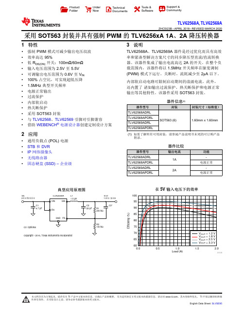
Load (A)E f f i c i e n c y (%)0.00.51.0 1.52.06065707580859095100D008V INV OUTL1TLV62569AProduct Folder Order Now Technical Documents Tools &SoftwareSupport &CommunityTLV62568A ,TLV62569AZHCSI23B –APRIL 2018–REVISED MARCH 2020采用SOT563封装并具有强制PWM 的TLV6256xA 1A 、2A 降压转换器1特性•强制PWM 模式可减少输出电压纹波•效率高达95%•低R DS(ON)开关:100m Ω/60m Ω•输入电压范围为2.5V 至5.5V •可调输出电压范围为0.6V 至V IN •100%占空比,可实现超低压降• 1.5MHz 典型开关频率•电源正常输出•过流保护•内部软启动•热关断保护•采用SOT563封装•与TLV62568、TLV62569引脚对引脚兼容•借助WEBENCH ®电源设计器创建定制设计方案2应用•通用负载点(POL)电源•STB 和DVR •IP 网络摄像头•无线路由器•固态硬盘(SSD)–企业级3说明TLV62568A 、TLV62569A 器件是经过优化而具有高效率和紧凑型解决方案尺寸的同步降压型直流/直流转换器。
该器件集成了输出电流高达2A 的开关。
在整个负载范围内,该器件将以1.5MHz 开关频率在脉宽调制(PWM)模式下运行。
关断时,流耗减少至2μA 以下。
内部软启动电路可限制启动期间的浪涌电流。
此外,还内置了诸如输出过流保护、热关断保护和电源正常输出等其他特性。
该器件采用SOT563封装。
器件信息(1)器件型号封装封装尺寸(标称值)TLV62568ADRL SOT563(6)1.60mm x 1.60mmTLV62568APDRL TLV62569ADRL TLV62569APDRL(1)如需了解所有可用封装,请参阅产品说明书末尾的可订购产品附录。
电火花机的故障检修
故障检修是一个不断深化的认识过程,寻找故障的方法和程序既有一定规律,但又不是一个固定不变的模式,根据不同的情况,灵活应用不同的方法,制订出一个可*而又周密的检修方案,才能收到事半功倍的效果。
(1)机型:低速走丝线切割机CUT100D故障现象:不能自动穿丝。
故障检修:自动穿丝时,从上机头喷嘴喷出的水流正常,但下机头喷嘴本应吸水,却向外喷水。
检查水箱管路,发现节流阀(旁接一管可作吸水用)下的阀门被关死了,打开后穿丝正常。
但穿孔时发现穿孔机头上的电极一碰到工件,立即抬刀,不能放电加工。
这有两种可能:放电板故障或连线故障。
本着先易后难的原则先检查连线,发现有一负极连线已断,连好后,故障排除。
在低速走丝线切割机CUT150HSS上也发生类似故障,现象是不能放电加工。
根据经验,遇到这种情况,应优先考虑连线是否良好。
放电板故障,只遇到过一次:是在低速走丝线切割机SPRINT20上出现故障信息735。
经查是由于7号放电板 PMO211灰尘太多造成的。
(2)机型:低速走丝线切割机CUT100D故障信息:104。
故障现象:机床回零点时,向U轴负方向移动机床至极限-30.50mm处时,机床仍然不停(手压行程开关向U轴正方向移动时,机床只能回到零点),直冲到-36.00mm处被顶死,只得人为暂停。
故障检修:拆下行程开关,用万用表测WID282电路板J5插座21、22脚,+20V 输入电压正常。
关机,手压行程开关,用万用表测 WID282电路板J5插座21、22脚,通断显示正常。
初步断定是STB203、IMC202两块控制板有问题。
将STB201、STB202、 STB203电路板(STB202电路板与此故障无关,当时怕换乱了,就一齐换掉)与SPRINT20机床的相同电路板互换。
故障依旧。
又换相关的 DBE201、IMC202、DMC201、DMC202、SBC201电路板。
这时向U轴正方向能移动,却不能冲水了(STB202电路板GL4、 GL6指示灯不亮。
Maxim Integrated产品MAX9638评估板说明说明书

_______________________________________________________________ Maxim Integrated Products 1For pricing, delivery, and ordering information, please contact Maxim Direct at 1-888-629-4642, or visit Maxim’s website at .MAX9638 Evaluation KitEvaluates: MAX9638General DescriptionThe MAX9638 evaluation kit (EV kit) provides a proven design to evaluate the MAX9638 low-power, low-noise, CMOS input op amp, which is suitable for photodiode transimpedance front-ends in portable medical instruments. The EV kit circuit is preconfigured as a noninverting amplifier, but can easily be adapted to other topologies by changing a few components. The EV kit comes with a MAX9638AVB+ installed.FeaturesS Accommodates Noninverting and DifferentialOp-Amp ConfigurationsS Component Pads Allow for Lowpass andHighpass Sallen-Key FilterS Proven PCB LayoutS Fully Assembled and TestedOrdering Information19-5577; Rev 0; 9/10+Denotes lead(Pb)-free and RoHS compliant.Component ListComponent SupplierNote: Indicate that you are using the MAX9638 when contacting this component supplier.PARTTYPEMAX9638EVKIT+EV Kit DESIGNATION QTY DESCRIPTIONR3, R4, R7, R9, R13, R140Not installed, resistors (0603)R5, R10210k I Q 1% resistors (0603)R6, R8, R11, R1240I Q 5% resistors (0603)TP1–TP88Red test pointsU11Dual low-power, rail-to-rail I/O op amp (10 UTQFN)Maxim MAX9638AVB+—4Shunts (JU1–JU4)—1PCB: MAX9638 EVALUATION KIT+SUPPLIERPHONEWEBSITEMurata Electronics North America MAX9638 Evaluation Kit E v a l u a t e s : M A X 96382 ______________________________________________________________________________________Quick StartRequired Equipment• MAX9638 EV kit • 3.3V DC power supply (e.g., Agilent E3620A)• Precision voltage source •Digital multimeter (DMM)ProcedureThe EV kit is fully assembled and tested. Follow the steps below to verify board operation:1) Connect the positive terminal of the power supply tothe VDD pad and the ground terminal to the nearest GND and VSS pads.2) Connect the positive terminal of the precision voltagesource to INAP (TP2). Connect the negative terminal of the precision voltage source to the GND pad.3) Connect the INAM (TP1) to the GND pad.4) Connect the DMM to monitor the voltage on OUTA(TP4). With the 10k I feedback resistor (R5) and 1k I series resistor (R1), the gain is 11 (noninverting con-figuration).5) Turn on the 3.3V power supply.6) Apply 100mV from the precision voltage source.Observe the output at OUTA on the DMM. OUTA should read approximately 1.1V.7) Apply 200mV from the precision voltage source.OUTA should read approximately 2.2V.Detailed Description of HardwareThe MAX9638 EV kit provides a proven design to evaluate the MAX9638 low-power, low-noise, CMOS input op amp, which is suitable for photodiode tran-simpedance front-ends in portable medical instruments. The EV kit circuit is preconfigured as a noninverting amplifier, but can easily be adapted to other topologies by changing a few components.Op-Amp ConfigurationsThe device is a single-supply op amp that is ideal for differential sensing, noninverting amplification, buffering, and filtering. A few common configurations are shown in the next few sections.Noninverting ConfigurationThe EV kit comes preconfigured as a noninverting ampli-fier. The gain is set by the ratio of R5 and R1 for op amp A and R10 and R15 for op amp B. The EV kit comes pre-configured for a gain of 11 on both op amps. The output voltage for the noninverting configuration is given by the equation below:OUTA INAP OS R5V (1)(V V )R1=++andOUTB INBP OS R10V (1)(V V )R15=++Table 1. Jumper Descriptions (JU1–JU4)*Default position.JUMPER SHUNT POSITIONDESCRIPTIONJU11-2*Connects SHDNA of the device to VDD to put U1-A (op amp A) in normal operation. 2-3Connects SHDNA of the device to VSS to put op amp A in shutdown mode.JU21-2*Connects SHDNB of the device to VDD to put U1-B (op amp B) in normal operation. 2-3Connects SHDNB of the device to VSS to put op amp B in shutdown mode.JU31-2*Connects INA+ to INAP (TP2) through R2 and R8.2-3Connects INA+ to GND through R2 and R8.JU41-2*Connects INB+ to INBP (TP6) through R12 and R16.2-3Connects INB+ to GND through R12 and R16.MAX9638 Evaluation KitEvaluates: MAX9638_______________________________________________________________________________________ 3Differential AmplifierTo configure the EV kit as a differential amplifier, replace R1, R2, R3, and R5 with appropriate resistors for op amp A and R9, R10, R15, and R16 for op amp B. When R1 = R2 and R5 = R3, and R10 = R9 and R15 = R16, the CMRR of the differential amplifiers is determined by the matching of the resistor ratios R1/R2 and R3/R5, and R9/R10 and R15/R16:OUTA INAP INAM V GainA (V V )=−where:R5R3GainA R1R2==andOUTB INBP INBM V GainB (V V )=−where:R10R9GainB R15R16==Sallen-Key ConfigurationThe Sallen-Key topology is ideal for filtering sensor signals with a 2nd-order filter and acting as a buffer. Schematic complexity is reduced by combining the filter and buffer operations. The EV kit can be configured in a Sallen-Key topology by replacing and populating a few components. The Sallen-Key topology is typically configured as a unity-gain buffer, which can be done by replacing R1 and R5 with 0I resistors for op amp A. The signal is noninverting and applied to INAP. The filter component pads are R2, R3, R4, and R8, where some have to be populated with resistors and others with capacitors. The same idea applies for op amp B; replace R10 and R15 with 0I resistors and the filter component pads are R9, R12, R14, and R16.Lowpass Sallen-Key FilterTo configure the op amp A Sallen-Key as a lowpass filter, populate the R2 and R8 pads with resistors and populatethe R3 and R4 pads with capacitors.The corner frequency and Q are then given by:C R4R2R8f Q ==The same idea applies for op amp B by replacing R9, R12, R14, and R16 with the appropriate components.Highpass Sallen-Key FilterTo configure the op amp A Sallen-Key as a highpass filter, populate the R3 and R4 pads with resistors and populate theR2 and R8 pads withcapacitors. The corner frequency and Q are then given by:C R3R2R8f Q ==The same idea applies for op amp B by replacing R9, R12, R14, and R16 with the appropriate components.Capacitive LoadsSome applications require driving large capacitive loads. To improve the stability of the amplifiers in such cases, replace R6 and R11 with a suitable resistor value to improve amplifier phase margin.MAX9638 Evaluation Kit E v a l u a t e s : M A X 96384 ______________________________________________________________________________________MAX9638 Evaluation KitEvaluates: MAX9638_______________________________________________________________________________________ 5Component SideMaxim cannot assume responsibility for use of any circuitry other than circuitry entirely embodied in a Maxim product. No circuit patent licenses are implied. Maxim reserves the right to change the circuitry and specifications without notice at any time.6 Maxim Integrated Products, 120 San Gabriel Drive, Sunnyvale, CA 94086 408-737-7600© 2010 Maxim Integrated ProductsMaxim is a registered trademark of Maxim Integrated Products, Inc.MAX9638 Evaluation Kit E v a l u a t e s : M A X 9638Revision HistoryREVISION NUMBERREVISION DATE DESCRIPTIONPAGES CHANGED9/10Initial release—。
海尔新型LED液晶彩电主要配置表

W W W APPL-IATMCE T R jw ET=*A.ITRIJSIG海笊新型LED 液晶彩电主要配置表□景曙光机型系列机芯配置屏型号电源名称与型号W F 丨配置遥控器型号LC55K31Y曲面MST6A638LSC550HN05澳源标配HTR-U08W LE32AL88G31CU32985低成本板卡N80CVTE 标配HTR-A07LE32AL88G31Z U32986低成本板卡N80CVTE 标配HTR-U08W LE32AL88U51U52984低成本板卡N80CVTE 标配HTR-U08WLE32B310G 、LE32B510F 兆驰三代机风行638LSC320AN09/LSC320AN10二合一机芯标配风行-A03LE32B3300W B9U 69三合一ST3151A05-8CVTE 无HTR-A07LE39B3500W B9638三合一LC390TU1A MTC 标配HTR-A03LE42A30G B9海思310CMI/V420HJ2/C4CVT标配HTR-A07LE42AL88U51U5638三合_V420HJ2-P01CVTE 标配HTR-U08W LE43AL88U51U5338HV430FHB -N40CVT标配HTR-A07LE43B510N U56A638三合一HV430FHB -N40CVT标配HTR-A07LQ49AL88U81A3U82T968LSC490FN01三华标配HTR-U15LQ49AL88U82A3U82T111+T966(4G)LSC490FN01/00907三华标配蓝牙HTR -U16LQ55AL88M52M52T101+T966(32G)LSC550FN10澳源/6518标配语音遥控器LQ55AL88U81A3U82T968LSC550FN10 -B 澳源标配HTR-U15LQ55AL88U82A3U82T101+T966(32G)LSC550FN10澳源/6518标配语音遥控器(转下页)(续表1)故障现象故障部位故障原因局部白色光团(晕光)T -C O N 逻辑电路一般是T -C O N 板白平衡电路失效所引起。
低功耗运算放大器型号说明书

引脚接线图图1. 8引脚MSOP 封装图2. 8引脚LFCSP 封装图3. 输出电压(V OH )至供电轨与负载电流的关系One Technology Way, P.O. Box 9106, Norwood, MA 02062-9106, U.S.A.Tel: 781.329.4700 ©2013 Analog Devices, Inc. All rights reserved.Technical Support Rev. 0Document FeedbackInformation furnished by Analog Devices is believed to be accurate and reliable. However , no responsibility is assumed by Analog Devices for its use, nor for any infringements of patents or other rights of third parties that may result from its use. Speci cations subject to change without notice. No license is granted by implication or otherwise under any patent or patent rights of Analog Devices. T rademarks and registered trademarks are the property of their respective owners.ADI 中文版数据手册是英文版数据手册的译文,敬请谅解翻译中可能存在的语言组织或翻译错误,ADI 不对翻译中存在的差异或由此产生的错误负责。
如需确认任何词语的准确性,请参考ADI 提供的最新英文版数据手册。
线切割事故案例

线切割事故案例故障检修是一个不断深化的认识过程,寻找故障的方法和程序既有一定规律,但又不是一个固定不变的模式,根据不同的情况,灵活应用不同的方法,制订出一个可而又周密的检修方案,才能收到事半功倍的效果。
(1)机型:低速走丝线切割机CUT100D故障现象:不能自动穿丝。
故障检修:自动穿丝时,从上机头喷嘴喷出的水流正常,但下机头喷嘴本应吸水,却向外喷水。
检查水箱管路,发现节流阀(旁接一管可作吸水用)下的阀门被关死了,打开后穿丝正常。
但穿孔时发现穿孔机头上的电极一碰到工件,立即抬刀,不能放电加工。
这有两种可能:放电板故障或连线故障。
本着先易后难的原则先检查连线,发现有一负极连线已断,连好后,故障排除。
在低速走丝线切割机CUT150HSS上也发生类似故障,现象是不能放电加工。
根据经验,遇到这种情况,应优先考虑连线是否良好。
放电板故障,只遇到过一次:是在低速走丝线切割机SPRINT20上出现故障信息735。
经查是由于7号放电板PMO211灰尘太多造成的。
(2)机型:低速走丝线切割机CUT100D故障信息:104。
故障现象:机床回零点时,向U轴负方向移动机床限-30。
50mm处时,机床仍然不停(手压行程开关向U轴正方向移动时,机床只能回到零点),直冲到-36。
00mm处被顶死,只得人为暂停。
故障检修:拆下行程开关,用万用表测WID282电路板J5插座21、22脚,+20V输入电压正常。
关机,手压行程开关,用万用表测WID282电路板J5插座21、22脚,通断显示正常。
初步断定是STB203、IMC202两块控制板有问题。
将STB201、STB202、STB203电路板(STB202电路板与此故障无关,当时怕换乱了,就一齐换掉)与SPRINT20机床的相同电路板互换。
故障依旧。
又换相关的DBE201、IMC202、DMC201、DMC202、SBC201电路板。
这时向U轴正方向能移动,却不能冲水了(STB202电路板GL4、GL6指示灯不亮。
接收机密码大全
卫星数字接收机启用密码大全1.亚视达5288(海克威):(1)首先按遥控器“MENU”键进入系统设置,按“OK”进入。
(2)进入“系统设置”,选择“默认设置”。
(3)画面出现“恢复默认设置”框,先按遥控器静音键,再按遥控器方向“上”键,这时画面出现“请输入密码”框,输入密码1270即可。
2.亚视达2688:进入默认设置中,按静音键即可。
3.卓异ZY5518Y(东方龙。
小飞鸽。
小孔雀。
小帅哥等)盲扫功能:按遥控菜单键。
出现卓异主菜单时,虽然画面没有提示,便只要输入密码即可,可输入以下几组密码:309700.5168.1698.305518。
因不同批次的机器密码是不是同的,可以逐个一试。
如果正确,会有“出厂参数恢复,请稍等”的提示。
这步完成再按自动搜索,确认即可进入盲扫。
4.卓异→飞天龙:密码1234。
5.通达:节目加→按音量减键4次→静音即可。
6.小神童。
挑战者等:恢复出厂设置→确认,输入6678即可。
7.经天。
威乐士2288,年华。
沧浪等:恢复出厂设置→确认→静音→节目7065即可。
8.跃佳航天等:恢复出厂设置→确认→静音→节目加→7065;菜单按静音键5秒钟→屏幕显示“数据存储中”即可。
9.创维DVB-SOI工程机:密码13572468。
10.创维高级用户的开启密码:13572468。
11.RCA-993S密码:6931。
12.天域密码:1001。
13.DX680密码:0000。
14.长虹万能码:138168。
15.同洲5288的进入方法:打开主菜单→进入转发器设置→依次按声道键→信息键→00000。
16.同洲3188CSE:菜单→节目设置→节目加→信息键→声道键。
密码0000。
17.同洲5288等:菜单→输入156988即可。
18.海克威5688新版机盲扫密码:0000,老版机密码:1270 19.海克威(天王星):在恢复出厂时按静音键输入1270 20.海克威HIC-3288C进入主菜单,用遥控器数字键输入1270即可。
sbRIO-9638 Kit 产品说明说明书

Quick Reference GuidesbRIO-9638© 2019 National Instruments All rights reserved.Information is subject to change without notice. Refer to the NI Trademarks and Logo Guidelines at /trademarks for more information on NI trademarks. Other product and company names mentioned herein are trademarks or trade names of their respective companies. For patents covering NI products/technology, refer to the appropriate location: Help»Patents in your software, the patents.txt file on your media, or the National Instruments Patents Notice at /patents . You can find information about end-user license agreements (EULAs) and third-party legal notices in the readme file for your NI product. Refer to the Export Compliance Information at /legal/export-compliance for the NI global trade compliance policy and how to obtain relevant HTS codes, ECCNs, and other import/export data. NI MAKES NO EXPRESS OR IMPLIED WARRANTIES AS TO THE ACCURACY OF THE INFORMATION CONTAINED HEREIN AND SHALL NOT BE LIABLE FOR ANY ERRORS. U.S. Government Customers: The data contained in this manual was developed at private expense and is subject to the applicable limited rights and restricted data rights as set forth in FAR 52.227-14, DFAR 252.227-7014, and DFAR 252.227-7015.For a complete list of resources go to the following URL: ni .com/r /sbrio377899A-03. Aug19Connect to the Host Computer via Ethernet1. Power on the host computer.2. Connect the sbRIO-9638 to the host computer using a standard Category 5 (CAT-5) or better shielded, twisted-pair Ethernet cable.Connect to Power1. Ensure that your power supply is powered off.2. Insert the power connector plug into the power connector receptacle of the sbRIO-9638 until the connector latches into place.3. Turn on the power supply.Connect to the Host Computer via USB1. Power on the host computer.2. Connect the USB Type-C 2.0 device port of the sbRIO-9638 to the host computer using a Type-C to Type-A USB cable.ORsbRIO-9638 Block DiagramCAN Pinout123. User1 LED4. User FPGA1 LED5. SD in Use LED1. Connector1 (DIO Port)8. Power terminal2. Connector0 (MIO Port) 9. CAN port3. RS-485 port (ASRL3) 10. USB Type-C 2.0 device port4. RS-232 port (ASRL2) 11. USB Type C 3.1 host port5. USB Type-A 2.0 host port 12. RS-232 serial port (ASRL1)6. USB Type-A 2.0 host port 13. Ethernet ports7. MicroSD portsbRIO-9638 Parts Locator Diagram RS-485 (ASRL3) PinoutConnector1 (DIO port) PinoutConnector0 (MIO port) Pinout。
输入运算放大器MAX9636,MAX9637,MAX9638

输入运算放大器MAX9636,MAX9637,MAX9638
佚名
【期刊名称】《电子设计工程》
【年(卷),期】2011(19)4
【摘要】MAX9636,MAX9637/MAX9638是单电源供电、CMOS输入运算放大器,以极低的静态电流提供较宽的频带,可理想用于便携式医疗仪器、便携式多媒体播放器、烟雾探测器等各种电池供电设备。
极低的输入偏置电流、低输入电流噪声和低输入电压噪声特性相结合,允许器件连接光电二极管、压电传感器等高阻信号源。
这些器件还非常适合通用的信号处理功能.例如各种便携式、电池供电产品中的滤波和放大电路。
【总页数】1页(P77-77)
【关键词】运算放大器;S输入;便携式多媒体播放器;电池供电设备;单电源供电;烟雾探测器;光电二极管;压电传感器
【正文语种】中文
【中图分类】TN722.77
【相关文献】
1.同相输入运算放大器输入电阻的讨论 [J], 唐民丽;吴恒玉
2.一种恒跨导输入级轨到轨运算放大器的设计 [J], 王健;朱明魁
3.集成运算放大器的特性及其在音频放大器中的应用(十四) 音质评价高的FET输入运算放大器OPA2134 [J], 张达
4.一种低偏置电流、高输入阻抗运算放大器电路设计 [J], 代松;唐毓尚;包磊;袁兴林;陈旺云
因版权原因,仅展示原文概要,查看原文内容请购买。
- 1、下载文档前请自行甄别文档内容的完整性,平台不提供额外的编辑、内容补充、找答案等附加服务。
- 2、"仅部分预览"的文档,不可在线预览部分如存在完整性等问题,可反馈申请退款(可完整预览的文档不适用该条件!)。
- 3、如文档侵犯您的权益,请联系客服反馈,我们会尽快为您处理(人工客服工作时间:9:00-18:30)。
IMPORTANT NOTICE
Texas Instruments and its subsidiaries (TI) reserve the right to make changes to their products or to discontinue any product or service without notice, and advise customers to obtain the latest version of relevant information to verify, before placing orders, that information being relied on is current and complete. All products are sold subject to the terms and conditions of sale supplied at the time of order acknowledgement, including those pertaining to warranty, patent infringement, and limitation of liability.
TI warrants performance of its semiconductor products to the specifications applicable at the time of sale in accordance with TI’s standard warranty. Testing and other quality control techniques are utilized to the extent TI deems necessary to support this warranty. Specific testing of all parameters of each device is not necessarily performed, except those mandated by government requirements.
CERTAIN APPLICATIONS USING SEMICONDUCTOR PRODUCTS MAY INVOLVE POTENTIAL RISKS OF DEATH, PERSONAL INJURY, OR SEVERE PROPERTY OR ENVIRONMENTAL DAMAGE (“CRITICAL APPLICATIONS”). TI SEMICONDUCTOR PRODUCTS ARE NOT DESIGNED, AUTHORIZED, OR WARRANTED TO BE SUITABLE FOR USE IN LIFE-SUPPORT DEVICES OR SYSTEMS OR OTHER CRITICAL APPLICATIONS. INCLUSION OF TI PRODUCTS IN SUCH APPLICATIONS IS UNDERSTOOD TO BE FULLY AT THE CUSTOMER’S RISK.
In order to minimize risks associated with the customer’s applications, adequate design and operating safeguards must be provided by the customer to minimize inherent or procedural hazards.
TI assumes no liability for applications assistance or customer product design. TI does not warrant or represent that any license, either express or implied, is granted under any patent right, copyright, mask work right, or other intellectual property right of TI covering or relating to any combination, machine, or process in which such semiconductor products or services might be or are used. TI’s publication of information regarding any third party’s products or services does not constitute TI’s approval, warranty or endorsement thereof.
Copyright © 1998, Texas Instruments Incorporated。
