Combine%20MII
各种MII详解(MII,GMII,RGMII,RMII,SMII,SSMII,TBI,RTBI)

简介MII是英文Medium Independent Interface的缩写,翻译成中文是“介质独立接口”,该接口一般应用于以太网硬件平台的MAC层和PHY层之间,MII接口的类型有很多,常用的有MII、RMII、SMII、SSMII、SSSMII、GMII、RGMII、SGMII、TBI、RTBI、XGMII、XAUI、XLAUI等。
下面对它们进行一一介绍。
MII接口:T XD(Transmit Data)[3:0]:数据发送信号,共4根信号线;RXD(Receive Data)[3:0]:数据接收信号,共4根信号线;TX_ER(Transmit Error):发送数据错误提示信号,同步于TX_CLK,高电平有效,表示TX_ER有效期内传输的数据无效。
对于10Mbps速率下,TX_ER不起作用;RX_ER(Receive Error):接收数据错误提示信号,同步于RX_CLK,高电平有效,表示RX_ER有效期内传输的数据无效。
对于10Mbps速率下,RX_ER不起作用;TX_EN(Transmit Enable):发送使能信号,只有在TX_EN有效期内传的数据才有效;RX_DV(Reveive Data Valid):接收数据有效信号,作用类型于发送通道的TX_EN;TX_CLK:发送参考时钟,100Mbps速率下,时钟频率为25MHz,10Mbps速率下,时钟频率为2.5MHz。
注意,TX_CLK时钟的方向是从PHY侧指向MAC侧的,因此此时钟是由PHY提供的。
RX_CLK:接收数据参考时钟,100Mbps速率下,时钟频率为25MHz,10Mbps速率下,时钟频率为2.5MHz。
RX_CLK也是由PHY侧提供的。
CRS:Carrier Sense,载波侦测信号,不需要同步于参考时钟,只要有数据传输,CRS就有效,另外,CRS只有PHY在半双工模式下有效;COL:Collision Detectd,冲突检测信号,不需要同步于参考时钟,只有PHY在半双工模式下有效。
combine的用法及例子

combine的用法及例子一、什么是combine在计算机科学中,combine是一个用于合并、汇总或组合数据的功能。
它可以将多个数据集合、列表或数组等进行组合操作,生成一个新的数据集合,其中包含了原始数据的所有元素。
二、combine的常见用法1. 列表或数组的合并combine函数常常被用于将多个列表或数组进行合并。
假设有两个列表A和B,我们可以使用combine函数将它们合并成一个新的列表。
例如,假设有两个列表A=[1, 2, 3]和B=[4, 5, 6],我们可以使用combine函数将它们合并为C=[1, 2, 3, 4, 5, 6]。
2. 字符串的拼接除了对列表和数组进行合并外,在处理字符串时,也经常需要使用combine函数进行字符串的拼接操作。
假设有两个字符串str1="Hello," 和 str2=" world!",我们可以使用combine函数将它们拼接成一个新的字符串。
例如,通过将str1和str2使用combine函数进行拼接得到新字符串"Hello,world!"。
3. 数据集的联结在数据分析和数据库操作中,当需要对多个数据集进行联结时,通常会使用到combine函数。
比如,在SQL语言中,有一个SELECT语句能够实现两个表按照某个列进行联结,并生成一个包含两张表所有信息的新表。
这个操作通常可以使用combine函数来实现。
4. 图片或动画合成在图形处理领域,combine函数也被广泛应用于图片和动画的合成过程中。
通过将多张图片或动画帧使用combine函数进行融合,可以得到一个新的图片或动画效果。
5. 音频混音类似于图片和动画的合成,在音频处理方面,使用combine函数可以实现多个音频源的混音。
将不同的音频片段按照一定规则进行合并,可以产生出更丰富、更复杂的声音效果。
以上仅为combine使用场景中的几个例子,实际上,在计算机科学和工程领域中,combine函数有着广泛而灵活的应用。
combine的用法

combine的用法Combine一个强大的函数库,可以应用于 iOS发中的很多功能。
本文将详细介绍 Combine用法,并通过实例帮助大家逐步深入理解。
首先,让我们看看 Combine什么。
Combine苹果在 2019 WWDC 上推出的一种新的响应式编程框架,它可以用来简化开发过程中的数据流和异步操作。
它的几个特点是:1.有易于使用的 API,可为开发者提供一个易于使用的响应式编程环境。
2. 使用 Combine,开发者可以非常容易地监控复杂的数据流。
3.持多种格式的输入和输出,可以满足不同的数据流需求。
4.持异常处理,可以让开发者处理程序出现错误的情况。
除了上面提到的功能,Combine具有更多强大的功能,有助于开发者更好地管理复杂的数据流和异步操作。
以上是 Combine介绍,接下来让我们看看 Combine么用。
首先,需要确定要监控的数据流。
Combine持多种格式的输入和输出,因此可以监控各种类型的数据流。
例如,可以监控一次性的值或可观察的值,以及异步发出的值。
之后,需要使用 Combine各种操作符来处理输入和输出。
Combine 持多种操作符,如 map、filter reduce,以及其他转换操作符,如combineLatest zip。
操作符可以用来转换和处理输入和输出数据,以便生成我们想要的结果。
最后,需要用异步处理去处理一些异常情况,这一点也是Combine大之处。
Combine持 error、catch retry作符,使开发者可以简单地处理异常,而不会影响程序的正常运行。
以上就是 Combine用法,从上面可以看出,Combine以帮助开发者简化开发过程中的数据流和异步操作,极大地提升了开发效率。
同时,它还具备强大的异常处理能力,使开发者可以容易地处理程序出现错误的情况。
总而言之,Combine一个功能强大的函数库,可以帮助开发者更好的处理数据流和异步操作,极大地提升开发效率。
各种MII接口详解

简介MII是英文Medium Independent Interface的缩写,翻译成中文是“介质独立接口”,该接口一般应用于以太网硬件平台的MAC层和PHY层之间,MII接口的类型有很多,常用的有MII、RMII、SMII、SSMII、SSSMII、GMII、RGMII、SGMII、TBI、RTBI、XGMII、XAUI、XLAUI等。
下面对它们进行一一介绍。
MII接口:T XD(Transmit Data)[3:0]:数据发送信号,共4根信号线;RXD(Receive Data)[3:0]:数据接收信号,共4根信号线;TX_ER(Transmit Error):发送数据错误提示信号,同步于TX_CLK,高电平有效,表示TX_ER有效期内传输的数据无效。
对于10Mbps速率下,TX_ER不起作用;RX_ER(Receive Error):接收数据错误提示信号,同步于RX_CLK,高电平有效,表示RX_ER有效期内传输的数据无效。
对于10Mbps速率下,RX_ER不起作用;TX_EN(Transmit Enable):发送使能信号,只有在TX_EN有效期内传的数据才有效;RX_DV(Reveive Data Valid):接收数据有效信号,作用类型于发送通道的TX_EN;TX_CLK:发送参考时钟,100Mbps速率下,时钟频率为25MHz,10Mbps速率下,时钟频率为2.5MHz。
注意,TX_CLK时钟的方向是从PHY侧指向MAC侧的,因此此时钟是由PHY提供的。
RX_CLK:接收数据参考时钟,100Mbps速率下,时钟频率为25MHz,10Mbps速率下,时钟频率为2.5MHz。
RX_CLK也是由PHY侧提供的。
CRS:Carrier Sense,载波侦测信号,不需要同步于参考时钟,只要有数据传输,CRS就有效,另外,CRS只有PHY在半双工模式下有效;COL:Collision Detectd,冲突检测信号,不需要同步于参考时钟,只有PHY在半双工模式下有效。
MII,GMII,RMII介绍

MII (Media Independent Interface(介质无关接口)或称为媒体独立接口,它是IEEE-802.3定义的以太网行业标准。
它包括一个数据接口和一个MAC和PHY之间的管理接口。
数据接口包括分别用于发送器和接收器的两条独立信道,每条信道都有自己的数据、时钟和控制信号。
MII数据接口总共需要16个信号。
管理接口是个双信号接口:一个是时钟信号,另一个是数据信号。
通过管理接口,上层能监视和控制PHY。
MII (Management interface)只有两条信号线。
MII标准接口用于连接Fast Ethernet MAC-block与PHY。
表明在不对MAC硬件重新设计或替换的情况下,任何类型的PHY设备都可以正常工作。
在其他速率下工作的与MII等效的接口有:AUI(10M以太网)、GMII(Gigabit以太网)和XAUI(10-Gigabit以太网)。
MII总线在IEEE802.3中规定的MII总线是一种用于将不同类型的PHY与相同网络控制器(MAC)相连接的通用总线。
网络控制器可以用同样的硬件接口与任何PHY进行连接。
MII相关接口介绍:以太网媒体接口有:MII RMII SMII GMII所有的这些接口都从MII而来,MII是(Medium Independent Interface)的意思,是指不用考虑媒体是铜轴、光纤、电缆等,因为这些媒体处理的相关工作都有PHY或者叫做MAC 的芯片完成。
MII支持10兆和100兆的操作,一个接口由14根线组成,它的支持还是比较灵活的,但是有一个缺点是因为它一个端口用的信号线太多,如果一个8端口的交换机要用到112根线,16端口就要用到224根线,到32端口的话就要用到448根线,一般按照这个接口做交换机,是不太现实的,所以现代的交换机的制作都会用到其它的一些从MII简化出来的标准,比如RMII、SMII、GMII等。
RMII是简化的MII接口,在数据的收发上它比MII接口少了一倍的信号线,所以它一般要求是50兆的总线时钟。
以太网MII接口类型大全
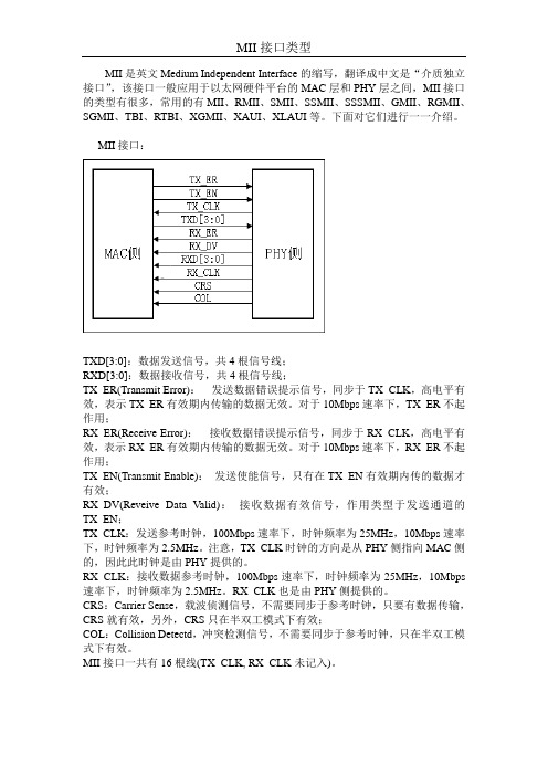
MII是英文Medium Independent Interface的缩写,翻译成中文是“介质独立接口”,该接口一般应用于以太网硬件平台的MAC层和PHY层之间,MII接口的类型有很多,常用的有MII、RMII、SMII、SSMII、SSSMII、GMII、RGMII、SGMII、TBI、RTBI、XGMII、XAUI、XLAUI等。
下面对它们进行一一介绍。
MII接口:TXD[3:0]:数据发送信号,共4根信号线;RXD[3:0]:数据接收信号,共4根信号线;TX_ER(Transmit Error):发送数据错误提示信号,同步于TX_CLK,高电平有效,表示TX_ER有效期内传输的数据无效。
对于10Mbps速率下,TX_ER不起作用;RX_ER(Receive Error):接收数据错误提示信号,同步于RX_CLK,高电平有效,表示RX_ER有效期内传输的数据无效。
对于10Mbps速率下,RX_ER不起作用;TX_EN(Transmit Enable):发送使能信号,只有在TX_EN有效期内传的数据才有效;RX_DV(Reveive Data Valid):接收数据有效信号,作用类型于发送通道的TX_EN;TX_CLK:发送参考时钟,100Mbps速率下,时钟频率为25MHz,10Mbps速率下,时钟频率为2.5MHz。
注意,TX_CLK时钟的方向是从PHY侧指向MAC侧的,因此此时钟是由PHY提供的。
RX_CLK:接收数据参考时钟,100Mbps速率下,时钟频率为25MHz,10Mbps 速率下,时钟频率为2.5MHz。
RX_CLK也是由PHY侧提供的。
CRS:Carrier Sense,载波侦测信号,不需要同步于参考时钟,只要有数据传输,CRS就有效,另外,CRS只在半双工模式下有效;COL:Collision Detectd,冲突检测信号,不需要同步于参考时钟,只在半双工模式下有效。
MII接口一共有16根线(TX_CLK, RX_CLK未记入)。
review points参考答案

1、什么是基本运算?什么是算法的时间复杂性(度)?什么是算法的渐近时间复杂性?答:基本运算是解决问题时占支配地位的运算(一般1种,偶尔两种)算法的时间复杂性(度)是指用输入规模的某个函数来表示算法的基本运算量。
算法的渐进时间复杂性是指当输入规模趋向于极限情形时(相当大)的时间复杂性。
2、表示渐进时间复杂性的三个记号的具体定义是什么?答:(1). T(n)= O(f(n)):若存在c > 0,和正整数n0≣1,使得当n≣n0时,总有T(n)≢c*f(n)。
(给出了算法时间复杂度的上界,不可能比c*f(n)更大)(2). T(n)=Ω(f(n)):若存在c > 0,和正整数n0≣1,使得当n≣n0时,存在无穷多个n ,使得T(n)≣c*f(n)成立。
(给出了算法时间复杂度的下界,复杂度不可能比c*f(n)更小)(3).T(n)= Θ(f(n)):若存在c1,c2>0,和正整数n0≣1,使得当n≣n0时,总有T(n)≢c1*f(n),且有无穷多个n,使得T(n)≣c2*f(n)成立,即:T(n)= O(f(n))与T(n)=Ω(f(n))都成立。
(既给出了算法时间复杂度的上界,也给出了下界)3、什么是最坏情况时间复杂性?什么是平均情况时间复杂性?答:最坏情况时间复杂性是规模为n的所有输入中,基本运算执行次数为最多的时间复杂性。
平均情况时间复杂性是规模为n的所有输入的算法时间复杂度的平均值(一般均假设每种输入情况以等概率出现)。
4、一般认为什么是算法?什么是计算过程?算法研究有哪几个主要步骤?主要从哪几个方面评价算法?答:一般认为,算法是由若干条指令组成的有穷序列,有五个特性 a.确定性(无二义)b.能行性(每条指令能够执行)c.输入 d.输出 e.有穷性(每条指令执行的次数有穷)只满足前4条而不满足第5条的有穷指令序列通常称之为计算过程。
算法研究的主要步骤是1)设计2)表示3)确认,合法输入和不合法输入的处理4)分析5)测试。
MII接口、MAC、PHY详解

MII接口详解【转】词条简介MII (Media Independent Interface(介质无关接口);或称为媒体独立接口,它是IEEE-802.3定义的以太网行业标准。
它包括一个数据接口,以及一个MAC 和PHY 之间的管理接口。
数据接口包括分别用于发送器和接收器的两条独立信道。
每条信道都有自己的数据、时钟和控制信号。
MII数据接口总共需要16个信号。
管理接口是个双信号接口:一个是时钟信号,另一个是数据信号。
通过管理接口,上层能监视和控制PHY。
MII (Management interface)只有两条信号线。
MII标准接口用于连快Fast Ethernet MAC-block与PHY。
"介质无关"表明在不对MAC硬件重新设计或替换的情况下,任何类型的PHY设备都可以正常工作。
在其他速率下工作的与 MII等效的接口有:AUI(10M 以太网)、GMII (Gigabit 以太网)和XAUI(10-Gigabit 以太网)。
MII总线在IEEE802.3中规定的MII总线是一种用于将不同类型的PHY与相同网络控制器(MAC)相连接的通用总线。
网络控制器可以用同样的硬件接口与任何PHY 进行连接。
MII相关接口介绍以太网媒体接口有:MII RMII SMII GMII所有的这些接口都从MII而来,MII是(Medium Independent Interface)的意思,是指不用考虑媒体是铜轴、光纤、电缆等,因为这些媒体处理的相关工作都有PHY或者叫做MAC的芯片完成。
MII支持10兆和100兆的操作,一个接口由14根线组成,它的支持还是比较灵活的,但是有一个缺点是因为它一个端口用的信号线太多,如果一个8端口的交换机要用到112根线,16端口就要用到224根线,到32端口的话就要用到448根线,一般按照这个接口做交换机,是不太现实的,所以现代的交换机的制作都会用到其它的一些从MII简化出来的标准,比如RMII、SMII、GMII等。
各种MII详解(MII,GMII,RGMII,RMII,SMII,SSMII,TBI,RTBI)

简介MII是英文Medium Independent Interface的缩写,翻译成中文是“介质独立接口”,该接口一般应用于以太网硬件平台的MAC层和PHY层之间,MII接口的类型有很多,常用的有MII、RMII、SMII、SSMII、SSSMII、GMII、RGMII、SGMII、TBI、RTBI、XGMII、XAUI、XLAUI等。
下面对它们进行一一介绍。
MII接口:TXD(Transmit Data)[3:0]:数据发送信号,共4根信号线;RXD(Receive Data)[3:0]:数据接收信号,共4根信号线;TX_ER(Transmit Error):发送数据错误提示信号,同步于TX_CLK,高电平有效,表示TX_ER有效期内传输的数据无效。
对于10Mbps速率下,TX_ER不起作用;RX_ER(Receive Error):接收数据错误提示信号,同步于RX_CLK,高电平有效,表示RX_ER有效期内传输的数据无效。
对于10Mbps速率下,RX_ER不起作用;TX_EN(Transmit Enable):发送使能信号,只有在TX_EN有效期内传的数据才有效;RX_DV(Reveive Data Valid):接收数据有效信号,作用类型于发送通道的TX_EN;TX_CLK:发送参考时钟,100Mbps速率下,时钟频率为25MHz,10Mbps速率下,时钟频率为2.5MHz。
注意,TX_CLK时钟的方向是从PHY侧指向MAC侧的,因此此时钟是由PHY提供的。
RX_CLK:接收数据参考时钟,100Mbps速率下,时钟频率为25MHz,10Mbps速率下,时钟频率为2.5MHz。
RX_CLK也是由PHY侧提供的。
CRS:Carrier Sense,载波侦测信号,不需要同步于参考时钟,只要有数据传输,CRS就有效,另外,CRS只有PHY在半双工模式下有效;COL:Collision Detectd,冲突检测信号,不需要同步于参考时钟,只有PHY在半双工模式下有效。
(完整版)以太网MII接口类型大全_MII、RMII、SMII、SSMII、SSSMII、GMII、
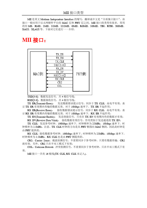
MII是英文Medium Independent Interface的缩写,翻译成中文是“介质独立接口”,该接口一般应用于以太网硬件平台的MAC层和PHY层之间,MII接口的类型有很多,常用的有MII、RMII、SMII、SSMII、SSSMII、GMII、RGMII、SGMII、TBI、RTBI、XGMII、XAUI、XLAUI等。
下面对它们进行一一介绍。
MII接口:TXD[3:0]:数据发送信号,共4根信号线;RXD[3:0]:数据接收信号,共4根信号线;TX_ER(Transmit Error):发送数据错误提示信号,同步于TX_CLK,高电平有效,表示TX_ER有效期内传输的数据无效。
对于10Mbps速率下,TX_ER不起作用;RX_ER(Receive Error):接收数据错误提示信号,同步于RX_CLK,高电平有效,表示RX_ER有效期内传输的数据无效。
对于10Mbps速率下,RX_ER不起作用;TX_EN(Transmit Enable):发送使能信号,只有在TX_EN有效期内传的数据才有效;RX_DV(Reveive Data Valid):接收数据有效信号,作用类似于发送通道的TX_EN;TX_CLK:发送参考时钟,100Mbps速率下,时钟频率为25MHz,10Mbps速率下,时钟频率为2.5MHz。
注意,TX_CLK时钟的方向是从PHY侧指向MAC侧的,因此此时钟是由PHY提供的。
RX_CLK:接收数据参考时钟,100Mbps速率下,时钟频率为25MHz,10Mbps速率下,时钟频率为2.5MHz。
RX_CLK也是由PHY侧提供的。
CRS:Carrier Sense,载波侦测信号,不需要同步于参考时钟,只要有数据传输,CRS 就有效,另外,CRS只在半双工模式下有效;COL:Collision Detectd,冲突检测信号,不需要同步于参考时钟,只在半双工模式下有效。
MII接口一共有16根线(TX_CLK, RX_CLK未记入)。
MII、RMII、GMII、RGMII接口介绍

MII、RMII、GMII、RGMII接口介绍2010-04-28 18:44:46| 分类:电子技术| 标签:|字号大中小订阅1 MII (Media Independent Interface )是介质无关接口。
40针。
MII类似于10Mbps以太网的连接单元接口(AUI)。
MII层定义了在100BASE-T MAC和各种物理层之间的标准电气和机械接口,这种标准接口类似于经典以太网中的AUI,它允许制造厂家制造与介质和布线无关的产品,利用外接MAU去连接实际的物理电缆。
MII和AUI的电气信号是不同的,AUI信号具有较强的、能驱动50米电缆的能力,而MII的信号是数字型的,只能驱动0.5米电缆。
MII采用一个类似于SCSI连接器的40芯小型连接器。
2 任天堂Wii主机名为“Mii”的新功能,重点是让用户可以DIY个性化定制游戏角色的形象。
观察其操作界面,可以发现这个功能让用户可以对软件提供的各种五官元素进行自由组装拼合,产生接近本人长相特征的虚拟Avatar形象。
这个系统表面上就是现在各种网络社区的Avatar系统的一个翻版,但它本质上最关键的一点是这个Avatar可以通过统一的API被应用到各种Wii的游戏软件中,强化用户体验的代入感。
词条简介MII (Media Independent Interface(介质无关接口);或称为媒体独立接口,它是IEEE-802.3定义的以太网行业标准。
它包括一个数据接口,以及一个MAC和PHY之间的管理接口。
数据接口包括分别用于发送器和接收器的两条独立信道。
每条信道都有自己的数据、时钟和控制信号。
MII数据接口总共需要16个信号。
管理接口是个双信号接口:一个是时钟信号,另一个是数据信号。
通过管理接口,上层能监视和控制PHY。
MII (Management interface)只有两条信号线。
MII标准接口用于连快Fast Ethernet MAC-block与PHY。
各种MII详解MIIGMIIRGMIIRMIISMIISSMIITBIRTBI
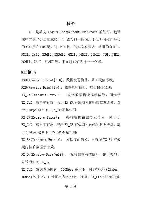
简介MII是英文Medium Independent Interface的缩写,翻译成中文是“介质独立接口”,该接口一般应用于以太网硬件平台的MAC层和PHY层之间,MII接口的类型有很多,常用的有MII、RMII、SMII、SSMII、SSSMII、GMII、RGMII、SGMII、TBI、RTBI、XGMII、XAUI、XLAUI等。
下面对它们进行一一介绍。
MII接口:TXD(Transmit Data)[3:0]:数据发送信号,共4根信号线;RXD(Receive Data)[3:0]:数据接收信号,共4根信号线;TX_ER(Transmit Error):发送数据错误提示信号,同步于TX_CLK,高电平有效,表示TX_ER有效期内传输的数据无效。
对于10Mbps速率下,TX_ER不起作用;RX_ER(Receive Error):接收数据错误提示信号,同步于RX_CLK,高电平有效,表示RX_ER有效期内传输的数据无效。
对于10Mbps速率下,RX_ER不起作用;TX_EN(Transmit Enable):发送使能信号,只有在TX_EN有效期内传的数据才有效;RX_DV(Reveive Data Valid):接收数据有效信号,作用类型于发送通道的TX_EN;TX_CLK:发送参考时钟,100Mbps速率下,时钟频率为25MHz,10Mbps速率下,时钟频率为2.5MHz。
注意,TX_CLK时钟的方向是从PHY侧指向MAC侧的,因此此时钟是由PHY提供的。
RX_CLK:接收数据参考时钟,100Mbps速率下,时钟频率为25MHz,10Mbps速率下,时钟频率为2.5MHz。
RX_CLK也是由PHY侧提供的。
CRS:Carrier Sense,载波侦测信号,不需要同步于参考时钟,只要有数据传输,CRS就有效,另外,CRS只有PHY在半双工模式下有效;COL:Collision Detectd,冲突检测信号,不需要同步于参考时钟,只有PHY在半双工模式下有效。
MII_MDIO接口详解

MII/MDIO接口详解2020-05-11 15:11:15| 分类: | 标签:|字号定阅本文要紧分析MII/RMII/SMII,和GMII/RGMII/SGMII接口的信号概念,及相关知识,同时本文也对RJ-45接口进行了总结,分析了在10/100模式下和1000M模式下的设计方式。
MII接口提供了MAC与PHY之间、PHY与STA(Station Management)之间的互联技术,该接口支持10Mb/s与100Mb/s的数据传输速度,数据传输的位宽为4位。
提到MII,就有可能涉及到RS,PLS,STA等名词术语,下面讲一下他们之间对应的关系。
所谓RS即Reconciliation sublayer,它的要紧功能主若是提供一种MII和MAC/PLS之间的信号映射机制。
它们(RS与MII)之间的关系如以下图:MII接口的Management Interface可同时操纵多个PHY,协议最多支持32个PHY,但有必然的限制:要符合协议要求的connector特性。
所谓Management Interface,即MDC信号和MDIO信号。
前面已经讲过RS与PLS的关系,和MII接口连接的对象。
它们是通过MII接口进行连接的,示用意如以下图。
由图可知,MII的Management Interface是与STA(Station Management)相连的。
接口支持10Mb/s和100Mb/s,且在两种工作模式下所有的功能和时序关系都是一致的,唯一不同的是时钟的频率问题。
要求PHY不必然必然要支持这两种速度,但必然要描述,通过Management Interface反馈给MAC。
下面将详细介绍MII接口的信号概念,时序特性等。
由于MII接口有MAC和PHY模式,因此,将会依照这两种不同的模式进行分析,同时还会对RMII/SMII进行介绍。
MII接口可分为MAC模式和PHY模式,一样说来MAC和PHY对接,可是MAC和MAC也是能够对接的。
网络MII接口与详解

硬件部分1MII接口简介:MII是英文Medium Independent Interface的缩写,翻译成中文是“介质独立接口”,该接口一般应用于MAC层和PHY层之间的以太网数据传输,也可叫数据接口。
(MAC与PHY 间的管理接口一般是MDIO)MII接口的类型有很多,常用的有MII、RMII、SMII、SSMII、SSSMII、GMII、RGMII、SGMII、TBI、RTBI、XGMII、XAUI、XLAUI等。
下面对它们进行一一介绍。
MII接口TXD(Transmit Data)[3:0]:数据发送信号,共4根信号线;RXD(Receive Data)[3:0]:数据接收信号,共4根信号线;TX_ER(Transmit Error):发送数据错误提示信号,同步于TX_CLK,高电平有效,表示TX_ER有效期内传输的数据无效。
对于10Mbps速率下,TX_ER不起作用;RX_ER(Receive Error):接收数据错误提示信号,同步于RX_CLK,高电平有效,表示RX_ER 有效期内传输的数据无效。
对于10Mbps速率下,RX_ER不起作用;TX_EN(Transmit Enable):发送使能信号,只有在TX_EN有效期内传的数据才有效;RX_DV(Reveive Data Valid):接收数据有效信号,作用类型于发送通道的TX_EN;TX_CLK:发送参考时钟,100Mbps速率下,时钟频率为25MHz,10Mbps速率下,时钟频率为2.5MHz。
注意,TX_CLK时钟的方向是从PHY侧指向MAC侧的,因此此时钟是由PHY 提供的。
RX_CLK:接收数据参考时钟,100Mbps速率下,时钟频率为25MHz,10Mbps速率下,时钟频率为2.5MHz。
RX_CLK也是由PHY侧提供的。
CRS:Carrier Sense,载波侦测信号,不需要同步于参考时钟,只要有数据传输,CRS就有效,另外,CRS只有PHY在半双工模式下有效;COL:Collision Detectd,冲突检测信号,不需要同步于参考时钟,只有PHY在半双工模式下有效。
RTL8212
INTEGRATED 10/100/1000 SINGLE/DUALGIGABIT ETHERNET TRANSCEIVERDATASHEETRev. 1.2 15 November 2005 Track ID: JATR-1076-21Realtek Semiconductor Corp.No. 2, Innovation Road II, Hsinchu Science Park, Hsinchu 300, TaiwanTel.: +886-3-578-0211. Fax: +886-3-577-6047 RTL8212-GR RTL8212N-GR RTL8211N-GRIntegrated 10/100/1000 Single/ Dual Gigabit Ethernet Transceiver ii Track ID: JATR-1076-21 Rev. 1.2COPYRIGHT©2005 Realtek Semiconductor Corp. All rights reserved. No part of this document may be reproduced, transmitted, transcribed, stored in a retrieval system, or translated into any language in any form or by any means without the written permission of Realtek Semiconductor Corp.DISCLAIMERRealtek provides this document “as is”, without warranty of any kind, neither expressed nor implied, including, but not limited to, the particular purpose. Realtek may make improvements and/or changes in this document or in the product described in this document at any time. This document could include technical inaccuracies or typographical errors.TRADEMARKSRealtek is a trademark of Realtek Semiconductor Corporation. Other names mentioned in this document are trademarks/registered trademarks of their respective owners.USING THIS DOCUMENTThis document is intended for the hardware and software engineer’s general information on the Realtek RTL8212/RTL8212N/RTL8211N Integrated Circuits.Though every effort has been made to ensure that this document is current and accurate, more information may have become available subsequent to the production of this guide. In that event, please contact your Realtek representative for additional information that may help in the development process.REVISION HISTORY Revision Release Date Summary1.0 2005/08/10 First release.1.1 2005/09/09 1. Add RTL8211N-GR single PHYceiver.2. Correct typo for page 20 P0RXDV description.1.2 2005/11/15 1. Update datasheet and product name to RTL8212, RTL8212N andRTL8211N.2. Remove RSGMII interface from RTL8212 (QFP-128).Table of Contents1.General Description (9)2.Features (10)3.System Applications (10)4.System Application Diagrams (11)5.Block Diagram (13)6.Pin Assignments (14)6.1. RTL8212EDHS QFP-128P ACKAGE (14)6.2. P ACKAGE I DENTIFICATION (RTL8212EDHS QFP-128) (14)6.3. RTL8212N QFN-76P ACKAGE (15)6.4. P ACKAGE I DENTIFICATION (RTL8212N QFN-76) (15)6.5. RTL8211N QFN-76P ACKAGE (16)6.6. P ACKAGE I DENTIFICATION (RTL8211N QFN-76) (16)7.Pin Descriptions (17)7.1. M EDIA D EPENDENT I NTERFACE P INS (17)7.2. GMII/MII T RANSMIT I NTERFACE P INS (18)7.3. GMII/MII R ECEIVE I NTERFACE P INS (19)7.4. RGMII T RANSMIT I NTERFACE P INS (20)7.5. RGMII R ECEIVE I NTERFACE P INS (21)7.6. RSGMII I NTERFACE P INS (21)7.7. S ERIAL M ANAGEMENT I NTERFACE P INS (22)7.8. S ERIAL LED I NTERFACE P INS (22)7.9. S YSTEM C LOCK I NTERFACE P INS (23)7.10. C ONFIGURATION AND C ONTROL P INS (24)7.11. M ISCELLANEOUS P INS (25)7.12. P OWER AND G ROUND P INS (26)Integrated 10/100/1000 Single/ Dual Gigabit Ethernet Transceiver iii Track ID: JATR-1076-21 Rev. 1.28.1. MDI I NTERFACE (27)8.1.1.Crossover Detection and Auto Correction (27)8.1.2.Polarity Correction (28)8.1.3.MAC Interface (29)8.2. G IGABIT M EDIA I NDEPENDENT I NTERFACE (GMII/MII) (30)8.2.1.Reduced GMII (RGMII) (32)8.2.2.10/100 Functionality (33)8.2.3.TX_CTL and RX_CTL Coding (34)8.2.4.In-Band Status (36)8.2.5.Four RGMII Modes (36)8.3. R EDUCED S ERIAL GMII(RSGMII) (37)8.3.1.RSGMII Data Transfer (39)8.4. MDC/MDIO M ANAGEMENT I NTERFACE (40)8.4.1.Preamble Suppression (41)8.5. H ARDWARE C ONFIGURATION I NTERFACE (42)8.6. LED C ONFIGURATION (43)8.6.1.LED System Application Examples (43)8.6.2.Serial Stream Order (44)8.7. S YSTEM C LOCK I NTERFACE (44)8.8. R EGISTER D ESCRIPTIONS (45)8.8.1.Register Symbols (45)8.8.2.MII Specification Defined Registers (45)8.8.3.Register0: Control (46)8.8.4.Register1: Status (47)8.8.5.Register2: PHY Identifier 1 Register (48)8.8.6.Register3: PHY Identifier 2 Register (48)8.8.7.Register4: Auto-Negotiation Advertisement (49)8.8.8.Register5: Auto-Negotiation Link Partner Ability (50)8.8.9.Register6: Auto-Negotiation Expansion (51)8.8.10.Register7: Auto-Negotiation Page Transmit Register (51)8.8.11.Register8: Auto-Negotiation Link Partner Next Page Register (52)8.8.12.Register9: 1000Base-T Control Register (52)8.8.13.Register10: 1000Base-T Status Register (53)8.8.14.Register15: Extended Status (53)Integrated 10/100/1000 Single/ Dual Gigabit Ethernet Transceiver iv Track ID: JATR-1076-21 Rev. 1.29.1. A BSOLUTE M AXIMUM R ATINGS (54)9.2. O PERATING R ANGE (54)9.3. DC C HARACTERISTICS (55)9.4. AC C HARACTERISTICS (57)10.Design and Layout Guide (59)10.1. G ENERAL G UIDELINES (59)10.2. MII/GMII/RGMII S IGNAL L AYOUT G UIDELINES (59)10.3. RSGMII S IGNAL L AYOUT G UIDELINES (60)10.4. E THERNET MDI D IFFERENTIAL S IGNAL L AYOUT G UIDELINES (60)10.5. C LOCK C IRCUIT (60)10.6. P OWER P LANES (60)10.7. G ROUND P LANE (61)10.8. T RANSFORMER O PTIONS (61)11.Mechanical Dimensions (62)11.1. EDHS-QFP-128D IMENSIONS (RTL8212) (62)11.2. N OTES FOR EDHS-QFP-128D IMENSIONS (RTL8212) (63)11.3. QFN-76D IMENSIONS (RTL8211N&RTL8212N) (64)11.4. N OTES FOR QFN-76D IMENSIONS (RTL8211N&RTL8212N) (65)12.Ordering Information (66)Integrated 10/100/1000 Single/ Dual Gigabit Ethernet Transceiver v Track ID: JATR-1076-21 Rev. 1.2List of TablesTable 1. Pin Type Abbreviations (17)Table 2. Media Dependent Interface Pins (17)Table 3. GMII/MII Transmit Interface Pins (18)Table 4. GMII/MII Receive Interface Pins (19)Table 5. RGMII Transmit Interface Pins (20)Table 6. RGMII Receive Interface Pins (21)Table 7. RSGMII Interface Pins (21)Table 8. Serial Management Interface Pins (22)Table 9. Serial LED Interface Pins (22)Table 10. System Clock Interface Pins (23)Table 11. Configuration and Control Pins (24)Table 12. Miscellaneous Pins (25)Table 13. Power and Ground Pins (26)Table 14. Mapping of Twisted-Pair Outputs to RJ-45 Connectors (27)Table 15. Media Dependent Interface Pin Mapping (27)Table 16. Data Rates Supported Through Each Interface (29)Table 17. MAC Interface Modes of Operation (29)Table 18. Gigabit Media Independent Interface (30)Table 19. MAC Interface Modes of Operation (32)Table 20. TX_ER and TX_EN Encoding (34)Table 21. RX_ER and RX_DV Encoding (35)Table 22. RGMII Timing Modes (36)Table 23. Configuration Pin Definitions (42)Table 24. LED Mode (43)Table 25. LED Status (43)Table 26. Serial Stream Order (Mode 0) (44)Table 27. Serial Stream Order (Mode 1) (44)Table 28. MII Specification Defined Registers (45)Table 29. Register0: Control (46)Table 30. Register1: Status (47)Table 31. Register2: PHY Identifier 1 Register (48)Table 32. Register3: PHY Identifier 2 Register (48)Table 33. Register4: Auto-Negotiation Advertisement (49)Integrated 10/100/1000 Single/ Dual Gigabit Ethernet Transceiver vi Track ID: JATR-1076-21 Rev. 1.2Table 34. Register5: Auto-Negotiation Link Partner Ability (50)Table 35. Register6: Auto-Negotiation Expansion (51)Table 36. Register7: Auto-Negotiation Page Transmit Register (51)Table 37. Register8: Auto-Negotiation Link Partner Next Page Register (52)Table 38. Register9: 1000Base-T Control Register (52)Table 39. Register10: 1000Base-T Status Register (53)Table 40. Register15: Extended Status (53)Table 41. Absolute Maximum Ratings (54)Table 42. Operating Range (54)Table 43. DC Characteristics (55)Table 44. Digital Timing Characteristics (58)Table 45. Ordering Information (66)Integrated 10/100/1000 Single/ Dual Gigabit Ethernet Transceiver vii Track ID: JATR-1076-21 Rev. 1.2List of FiguresFigure 1. RTL8212N with 8-Port Gigabit MAC (RTL8369) (11)Figure 2. RTL8212 with 24+2G MAC (RTL8326) (12)Figure 3. Block Diagram (13)Figure 4. Pin Assignments (RTL8212 EDHS QFP-128) (14)Figure 5. Pin Assignments (RTL8212N QFN-76) (15)Figure 6. Pin Assignments (RTL8211N QFN-76) (16)Figure 7. Conceptual Example of Polarity Correction (28)Figure 8. GMII Signal Diagram (30)Figure 9. MII Signal Diagram (31)Figure 10. RGMII Signal Diagram (33)Figure 11. RGMII Data Transmission (34)Figure 12. RGMII Data Reception Without Error (35)Figure 13. RGMII Data Reception With Error (35)Figure 14. RSGMII Interconnection Diagram (37)Figure 15. Realtek 8G Switch Application with RSGMII (38)Figure 16. RSGMII Functional Block Diagram at Ethernet PHY Side (39)Figure 17. RSGMII Functional Block Diagram at Ethernet MAC Side (40)Figure 18. MDIO Read Frame Format (41)Figure 19. MDIO Write Frame Format (41)Figure 20. Clock Generated from MAC (RSGMII Mode) (44)Figure 21. MII Interface Reception Data Timing (57)Figure 22. MII Interface Transmission Data Timing (57)Integrated 10/100/1000 Single/ Dual Gigabit Ethernet Transceiver viii Track ID: JATR-1076-21 Rev. 1.21.General DescriptionThe RTL8212/RTL8212N/8211N integrate dual/single independent Gigabit Ethernet transceivers into a single IC and performs all the physical layer (PHY) functions for 10Base-T, 100Base-TX, and 1000Base-T Ethernet on category 3 (10Base-T) or category 5 UTP cable (except 1000Base-T half duplex operation).The device includes the PCS, PMA, and PMD sub-layers. They perform encoding/decoding, clock/data recovery, digital adaptive equalization, echo cancellers, cross-talk elimination, line driver, as well as all other required support circuit functions. The device also integrates an internal hybrid that allows the use of inexpensive 1:1 transformer modules.Each of the two independent transceivers features an industrial standard GMII, MII, and RGMII (Reduced Gigabit Media Independent Interface). To further reduce PCB trace complexity, the RTL8211N/8212N also provides an innovative 2.5Gbps serial interface – the Reduced Serial Gigabit Media Independent Interface (RSGMII). Both dual transceivers can simultaneously communicate with the MAC through the same RSGMII interface.The RTL8212/RTL8212N/8211N adopts mixed mode 0.13µm CMOS technology and analog line driver architecture that offers lower power consumption than DAC architecture.Two package types are available; a thermally-enhanced 128-pin EDHS-QFP (Exposed Drop-in Heat Sink QFP) package, and a QFN (Quad Flat No-Lead) 76-pin package. Integrated 10/100/1000 Single/Dual Gigabit Ethernet Transceiver9Track ID: JATR-1076-21 Rev. 1.22.FeaturesSingle/Dual integrated 10/100/1000Base-T Gigabit Ethernet transceiverSupports full duplex at 10/100/1000Mbps, and half duplex at 10/100MbpsSupports 2.5V I/O (3.3V input tolerance) GMII and RGMII interfaces in 10/100/1000 mode for RTL8212 (QFP-128 Package)Supports RSGMII (2.5Gbps serial high speed interface) in 10/100/1000 mode for RTL8212N and RTL8211N (QFN-76 Package)Crossover detection and auto correction at all 3 speedsAutomatic detection and correction of wiring pair swaps, pair skew, and pair polarity Supports serial LED modeLine driver architecture with low power dissipation PAVE= 0.78W/port3.3V, 1.8V, and 1.2V power supply (2.5V is generated by internal linear regulator forDigital I/O pads)Packages:EDHS QFP-128, 14x20mm, 0.5mm lead pitch packageQFN-76, 9x9mm, 0.4mm pitch package0.13µm CMOS process3.System ApplicationsHigh-density Gigabit Ethernet switches and routersIntegrated 10/100/1000 Single/Dual Gigabit Ethernet Transceiver10Track ID: JATR-1076-21 Rev. 1.24.System Application DiagramsFigure 1. RTL8212N with 8-Port Gigabit MAC (RTL8369)Integrated 10/100/1000 Single/Dual Gigabit Ethernet Transceiver11Track ID: JATR-1076-21 Rev. 1.2Figure 2. RTL8212 with 24+2G MAC (RTL8326)Integrated 10/100/1000 Single/Dual Gigabit Ethernet Transceiver12Track ID: JATR-1076-21 Rev. 1.2Integrated 10/100/1000 Single/Dual Gigabit Ethernet Transceiver 13 Track ID: JATR-1076-21 Rev. 1.25. Block DiagramXTAL2XTAL1CLK25M-IN CLK25M-OUT LEDCK LEDDAMDI_REFPAIR APAIR BPAIR CPAIR DMDC MDIOPHYADD[4..1]MODE[2..0]INTF_SEL[2..0]PnTXD[7..0]PnGTXC PnTXEN PnTXC PnCOL PnCRS PnRXD[7..0]PnRXC PnRXDV PnRXERSTXP STXN SRXP SRXN SDS_REFRESETBFigure 3. Block DiagramIntegrated 10/100/1000 Single/Dual Gigabit Ethernet Transceiver14 Track ID: JATR-1076-21 Rev. 1.26. Pin Assignments6.1. RTL8212 EDHS QFP-128 PackageV D D 12P 0R X D 5/P H Y A D R [4]V S S 12P 1T X D 7P 0R X D 7/I N T F _S E L [1]P 0R X D 6/I N T F _S E L [0]V S S 12P 0G T X C P 0R X D 2/P H Y A D R [1]P 0R X D 1V D D I O P 0M D I B P 0M D I B P 0M D I A P 0M D I A A V D D 33A V D D 18A V D D 1P 1M D I A P 1M D I A A V D D 3A V D D 1P 0M D I D A V S P 0M D I C P 0M D I C P 1M D I B M D I _R E P 1M D I D P 1M D I C P 1M D I C A V D D 1A V D D P L A V S S X TA L2A V S S P L P 0TX D 7A V S P 1M D I B P 1M D I D M D IOL E D D P 0TX D 1M D P 0TX D 6P 0TX D 4P 0TX D 3P 0TX D 2V D D 12V S S 12P 0TX D 5X TA L1A V D D 33A V D D 12A V S S P 0M O D E [0]/ P 0C R SV S S IO V D D IO P 0TX E N P 0TX C R T T L E D C R T T 2P 0TX D 0P 0M D I D A V S A V S A V D D 1A V D D 3N C A V S S N C A V S S N C N C S V D D 18S V D D 12C L K I N A T E S V D D IO P 1T X D 5V D D 12P 1T X D 0P 1T X D 3P 1T X D 4V S S 12P 1T X D 1P 1T X D 2P 1T X D 6V D D I O P 1C R S /P 1M O D E [0]P 0R X D 4/P H Y A D R [3]P 0R X D 3/P H Y A D R [2]V D D 12P 1T X C P 1G T X C P 1T X E N V D D 12D IS _A U T O X O VE R / P 0R X D 0P 0M O D E [3]/ P 0R X D VP 0M O D E [2]/ P 0R X E RP 0M O D E [1]/ P 0C O L P 0R X CV S S 12R V D D 33R V D D 33V D D 12V S S 12V D D IO P 1R X D 1P 1R X D 2 /R X D LY V S S 12P 1R X D 7P 1R X D 5P 1R X D 6P 1R X D 4/LE D M O D E V S S IO V D D 12P 1R X D 3 /TX D LY P 1R X C P 1R X E R /P 1M O D E [2]P 1C O L /P 1M O D E [1]V S S 12P 1R X D V /P 1M O D E [3]P 1R X D 0V D D 12V D D IO R E S E TBFigure 4. Pin Assignments (RTL8212 EDHS QFP-128)6.2. Package Identification (RTL8212 EDHS QFP-128)Green package is indicated by a ‘G’ in the location marked ‘T’ in Figure 4.Integrated 10/100/1000 Single/Dual Gigabit Ethernet Transceiver15 Track ID: JATR-1076-21 Rev. 1.26.3. RTL8212N QFN-76 PackageP 1M D I A P A V D D 18P 0M D I D N P 0M D I C P 0M D I B P P 0M D I C P P 1M D I A N P 1M D I D P P 1M D I D P 1M D I C N A V D D 18P 1M D I B P P 1M D I B N P 0M D I D P P 0M D I B N P 0M D I A P P 0M D I A N P 1M D I C P A V D D 18RVDD33RESETB AVDD12AVDD33MDIREF RTT2VDD12VDD12P1MODE[1]P1MODE[2]P1MODE[0]VDDIO NC VDDIO AVDDPLL AVDD18AVDD33P1MODE[3]RTT1VDDIO P0MODE[1]RVDD33VDD12DIS_AUTOXOVERP0MODE[3]MDC AVDD18AVDD33LEDCK LEDDA MDIO P0MODE[0]VDDIO PHYADR[1]NC P0MODE[2]S V D D 12S T X N C L K I N S R X N S R X P V D D I O V D D 12P H Y A D R [3]P H Y A D R [4]V D D 12S T X P V D D 12V D D 12N C P H Y A D R [2]S V D D 18NCS V S S 12S V S S 18V D D I O VDD12Figure 5. Pin Assignments (RTL8212N QFN-76)6.4. Package Identification (RTL8212N QFN-76)Green package is indicated by a ‘G’ in the location marked ‘T’ in Figure 5.Integrated 10/100/1000 Single/Dual Gigabit Ethernet Transceiver 16Track ID: JATR-1076-21Rev. 1.26.5.RTL8211N QFN-76 PackageFigure 6. Pin Assignments (RTL8211N QFN-76)6.6. Package Identification (RTL8211N QFN-76)Green package is indicated by a ‘G’ in the location marked ‘T’ in Figure 6.Integrated 10/100/1000 Single/Dual Gigabit Ethernet Transceiver 17 Track ID: JATR-1076-21 Rev. 1.27. Pin DescriptionsTable 1. Pin Type Abbreviations Pin Type Definition I Input O OutputI/O Bi-directional B Bias PU Internal pull-up PD Internal pull-down PWR Power GND GroundNote: The RTL8212/RTL8212N/RTL8211N is a dual-port/single Gigabit Ethernet transceiver. Each port, defined as Port0 and Port1 (Port 0 for RTL8211N), is independent of the other, and is identical in performance and functionality. In this document, these pins for each port are specified by the port number, pin name, and signal number, respectively.For example, GMII transmit data pin 7 for port0 is shown as: P0TXD77.1. Media Dependent Interface PinsTable 2. Media Dependent Interface PinsQFN76 Pin# QFP128 Pin# Pin Name Type Description1, 2 3, 4 6, 7 8, 9 11, 12 13, 14 16, 17 18, 197, 8 10, 11 13, 14 16, 17 20, 21 23, 24 26, 27 29, 30P0MDIAP/N P0MDIBP/N P0MDICP/N P0MDIDP/N P1MDIAP/N P1MDIBP/N P1MDICP/N P1MDIDP/NI/OMedia Dependent Interface A~D. For 1000Base-T operation, differential data from the media is transmitted and received on all four pairs. For 100Base-Tx and 10Base-T operation, only MDIAP/N and MDIBP/N are used. Auto MDIX can reverse the pairs MDIAP/N and MDIBP/N.Each of the differential pairs has an internal 100ohm termination resister.Pins 11, 12, 13, 14, 16, 17, 18, and 19 of the QFN-76 package are N.C pins for the RTL8211N-GR.TheRTL8211N-GR is available in a QFN-76 package only.Integrated 10/100/1000 Single/Dual Gigabit Ethernet Transceiver 18 Track ID: JATR-1076-21 Rev. 1.27.2. GMII/MII Transmit Interface PinsTable 3. GMII/MII Transmit Interface PinsQFN76 Pin# QFP128 Pin#Pin Name Type Description117 69 P0GTXCP1GTXC I GMII Transmit Clock. 125MHz input clock. All transmit inputs must be synchronized to this clock during 1000Base-Toperation. This clock can be stopped in 10/100Base-T modes, and also during Auto-Negotiation.116 68P0TXC P1TXC OMII Transmit Clock. All transmit inputs must be synchronized to this clock during 10/100 operation. It provides a 25MHz clock reference in 100Base-TX mode, and 2.5MHz clock reference in 10Base-T.The 25MHz clock is the default rate.118 70 P0TXENP1TXENIGMII/MII Transmit Enable. The synchronous input indicates that valid data is being driven on the TXD bus. As the RTL8212 does not support 1000Base-T half-duplex mode, thecarrier-extension symbol is not transmitted onto the cable.TXEN is synchronous to GTXC in 1000Base-T mode and synchronous to TXC in 10/100Base-TX mode.127 126 125 124 123 122 121 120 91 80 79 78 76 75 73 72 P0TXD7 P0TXD6 P0TXD5 P0TXD4 P0TXD3 P0TXD2 P0TXD1 P0TXD0 P1TXD7 P1TXD6 P1TXD5 P1TXD4 P1TXD3 P1TXD2 P1TXD1 P1TXD0I PDGMII/MII Transmit Data Bus. The width of this synchronous input bus varies with the speed mode: 1000: TXD[7:0] are used.10/100: TXD[3:0] are used; TXD[7:4] are ignored.TXD[7:0] is synchronous to GTXC in 1000Base-T mode and synchronous to TXC in 10/100Base-TX mode.Integrated 10/100/1000 Single/Dual Gigabit Ethernet Transceiver 19 Track ID: JATR-1076-21 Rev. 1.27.3. GMII/MII Receive Interface PinsTable 4. GMII/MII Receive Interface PinsQFN76 Pin# QFP128 Pin#Pin Name Type Description109 62 P0RXCP1RXCO PDGMII/MII Receive Clock. The GMII/MII Receive output clock is used to synchronize received signals. Its frequency depends upon the link speed: 1000: 125MHz 100: 25MHz 10: 2.5MHz107 60 P0RXDVP1RXDVO PDGMII/MII Receive Data valid. This synchronous output is asserted when valid data is driven on RXD.RXDV is synchronous to RXC.115 65 P0CRS P1CRSO PDGMII/MII Carrier Sense. This asynchronous output is asserted when a non-idle condition is detected at the twisted-pair interface, and de-asserted when idle or a valid end of stream delimiter is detected. In 10/100Base-T half duplex, CRS is also asserted during transmission.CRS is asynchronous to TXC and RXC.114 64 P0COL P1COLO PDGMII/MII Collision. This asynchronous output is asserted when a collision is detected in half-duplex modes. In full duplex mode, this out is forced low.COL is asynchronous to TXC, and RXC.110 63 P0RXER P1RXERO PDGMII/MII Receive Error. When RXER and RXDV are both asserted, the symbol indicates an error symbol is detected on the cable. Since RTL8212 don’t support 1000Base-T half-duplex mode, carrier-extension receive symbol (RXER is asserted with RXDV deasserted) is not valid.RXDV is synchronous to RXC.Integrated 10/100/1000 Single/Dual Gigabit Ethernet Transceiver 20 Track ID: JATR-1076-21 Rev. 1.2QFN76 Pin# QFP128 Pin#Pin Name Type Description93949697981011021064849515254555659P0RXD7 P0RXD6 P0RXD5 P0RXD4 P0RXD3 P0RXD2 P0RXD1 P0RXD0 P1RXD7 P1RXD6 P1RXD5 P1RXD4 P1RXD3 P1RXD2 P1RXD1 P1RXD0 O PDGMII/MII Receive Data Bus. The width of this synchronousoutput bus varies with the speed mode: 1000: RXD[7:0] are used.10/100: RXD[3:0] are used; RXD[7:4] are ignored.RXD[7:0] is synchronous to RXC.7.4. RGMII Transmit Interface PinsTable 5. RGMII Transmit Interface PinsQFN76 Pin# QFP128 Pin#Pin Name Type Description117 69 P0GTXCP1GTXCIRGMII Transmit Clock. All transmit inputs must besynchronized to this clock. Its frequency, with +/- 50ppm tolerance, depends upon the link speed: 1000: 125MHz 100: 25MHz 10: 2.5MHz123 122 121 120 76 75 73 72 P0TXD3P0TXD2 P0TXD1 P0TXD0 P1TXD3 P1TXD2 P1TXD1 P1TXD0I PDRGMII Transmit Data Bus. In RGMII 1000Base-T mode,TXD[3..0] runs at a double data rate with bits[3..0] presented on the rising edge of the GTXC, and bits[7..4] presented on the falling edge of the GTXC. TXD[7..4] are ignored in this mode.In RGMII 10/100Base-T modes, the transmitted data nibble is presented on TXD[3..0] on the rising edge of GTXC and duplicated on the falling edge of GTXC.118 70 P0TXEN/P0TXCTL P1TXEN/P1TXCTLI PDRGMII Transmit Control. In RGMII mode, TXEN is used as TXCTL. TXEN is presented on the rising edge of GTXC.A logical derivative of TXEN and TXER is presented on the falling edge of GTXC.Integrated 10/100/1000 Single/Dual Gigabit Ethernet Transceiver 21 Track ID: JATR-1076-21 Rev. 1.27.5. RGMII Receive Interface PinsTable 6. RGMII Receive Interface Pins QFN76 Pin# QFP128 Pin#Pin NameType Description 109 62 P0RXCP1RXCO RGMII Receive Clock. All RGMII receive outputs must be synchronized to this clock. Its frequency, with +/- 50ppm tolerance, depends upon the link speed:1000: 125MHz100: 25MHz10: 2.5MHz98 101 102 106 54 55 56 59 P0RXD3 P0RXD2 P0RXD1 P0RXD0 P1RXD3 P1RXD2 P1RXD1 P1RXD0 O PD RGMII Receive Data Bus. In RGMII 1000Base-T mode,RXD[3..0] runs at a double data rate with bits[3..0] presented onthe rising edge of the RXC and bits[7..4] presented on thefalling edge of the RXC. RXD[7..4] are ignored in this mode.In RGMII 10/100Base_T modes, the received data nibble ispresented on RXD[3..0] on the rising edge of RXC and duplicated on the falling edge of RXC.107 60 P0RXCTL/ P0RXDV P1RXCTL/ P1RXDV O PDRGMII Receive Control. In RGMII mode, RXDV is used asRXCTL. RXDV is presented on the rising edge of RXC.A logical derivative of RXDV and RXER is presented on thefalling edge of RXC.7.6. RSGMII Interface PinsTable 7. RSGMII Interface PinsQFN76Pin#QFP128 Pin# Pin Name Type Description 4445N/A SRXP SRXN O RSGMII Receive Pair. 2.5GHz differential serial output. The differential pair has an internal 100ohm termination resister.4950 N/A STXP STXNI RSGMII Transmit Pair. 2.5GHz differential serial input. The differential pair has an internal 100ohm termination resister.Integrated 10/100/1000 Single/Dual Gigabit Ethernet Transceiver 22 Track ID: JATR-1076-21 Rev. 1.27.7. Serial Management Interface PinsTable 8. Serial Management Interface Pins QFN76 Pin# QFP128 Pin#Pin Name Type Description71 1 MDC I Management Data Clock. The clock reference for the serialmanagement interface.70 128 MDIO I/O PU Management Data Input/Output. MDIO transfer managementdata; in and out of the device synchronous to the rising edge ofMDC.54 55 56 58 96 97 98 101 PHYADR[4]/P0RXD5 PHYADR[3]/ P0RXD4 PHYADR[2]/ P0RXD3 PHYADR[1]/P0RXD2O PD PHY Address Select. These pins are the four uppermost bits of the 5-bit IEEE-specified PHY address. The states of these four pins are latched during power-up or reset. The lowest bit of the 5-bit PHY address is hard-wired to each of the dual ports within the device. ‘0’ represents Port0, and ‘1’ represents Port1.7.8. Serial LED Interface PinsTable 9. Serial LED Interface PinsQFN76 Pin# QFP128 Pin#Pin Name Type Description72 2 LEDCK O Serial LED Clock. Reference output clock for serial LEDinterface.The 12.5MHz clock outputs periodically. Data is latched on therising edge of LEDCK.73 3 LEDDA O Serial LED Data Output. Serial bit stream of link statusinformation.32 52 LEDMODE/ P1RXD4 O PD Serial LED Mode Select. These pins are used to configure LEDoperation mode. The state of this pin is latched during power-up or reset. There are two LED display modes:0: Mode 01: Mode 1Integrated 10/100/1000 Single/Dual Gigabit Ethernet Transceiver 23 Track ID: JATR-1076-21 Rev. 1.27.9. System Clock Interface PinsTable 10. System Clock Interface Pins QFN76 Pin# QFP128 Pin#Pin Name Type Description42 XTAL1 I PHY Reference Clock Input. 25MHz +/- 50ppm tolerance crystalreference or oscillator input. When using a crystal, connect aloading capacitor from each pad to ground.When CLKIN is used this pin is not valid and should bepulled-low.The maximum XTAL1 input voltage is 1.8 V .41 XTAL2 O PHY Reference Clock Output. 25MHz +/- 50ppm tolerance crystalreference or oscillator output.When CLKIN is used this pin is not valid and should be floating.47 CLKIN I 25MHz Clock Input. 25MHz +/- 50ppm tolerance clock input.When RSGMII is used this pin is able to accept a 25MHz clocksignal generated from the MAC device (RTL8212N/RTL8211Nonly).The maximum CLKIN input voltage is 1.8V .Integrated 10/100/1000 Single/Dual Gigabit Ethernet Transceiver 24 Track ID: JATR-1076-21 Rev. 1.27.10. Configuration and Control PinsTable 11. Configuration and Control Pins QFN76 Pin# QFP128 Pin#Pin NameType Description 93 94 INTF_SEL[1]/P0RXD7INTF_SEL[0]/P0RXD6 O PD MAC Interface mode select. INTF_SEL[1:0] determines the MAC interface configuration for both port0 and port1: 00: RSGMII (default mode) 01: GMII10: RGMII11: Reserved6364 67 68 35 36 37 38 107 110 114 115 60 63 64 65 P0MODE[3]/ P0RXDV P0MODE[2]/ P0RXER P0MODE[1]/ P0COL P0MODE[0]/ P0CRS P1MODE[3]/ P1RXDV P1MODE[2]/ P1RXER P1MODE[1]/ P1COL P1MODE[0]/ P1CRS O PD Auto-Negotiation Configuration. PxMODE[3:0] presets each port’s advertise link ability (speed, duplex, and master/slave). The states of this pin is latched during power-up or reset. PxMODE[3:0] defined as: 0000=Auto-negotiation, advertise all capabilities, prefer MASTER. 0001=Auto-negotiation, advertise all capabilities, prefer SLA VE. 0010=Auto-negotiation, advertise only 100Base-TX half duplex. 0011=Auto-negotiation, advertise only 100Base-TX full duplex. 0100=Reserved. 0101=Reserved. 0110=Reserved. 0111=Reserved. 1000=Auto-negotiation, advertise only 1000Base-T full duplex, force MASTER. 1001=Auto-negotiation, advertise only 1000Base-T full duplex, force SLA VE. 1010=Auto-negotiation, advertise only 1000Base-T full duplex, prefer MASTER.1011=Auto-negotiation, advertise only 1000Base-T full duplex,prefer SLA VE.1100=Auto-negotiation, advertise all capabilities, force MASTER.1101=Auto-negotiation, advertise all capabilities, force SLA VE.1110=Auto-negotiation, advertise only 10Base-T half duplex.1111=Auto-negotiation, advertise only 10Base-T full duplex.54 TXDLY/ P1RXD3O PD GTXC Clock Delay Select. This pin enables GTXC input delay inRGMII mode (see Table 22 for detailed configuration). 55 RXDLY/ P1RXD2O PD RXC Clock Delay Select. This pin enables RXC output delay inRGMII mode (see Table 22 for detailed configuration). 62 106 DIS_AUTOXOVER/ P0RXD0O PD 1: Disable auto crossover detection 0: Enable auto crossover detection。
MII接口
MII接口详解词条简介MII (Media Independent Interface(介质无关接口);或称为媒体独立接口,它是IEEE-802.3定义的以太网行业标准。
它包括一个数据接口,以及一个MAC和PHY之间的管理接口。
数据接口包括分别用于发送器和接收器的两条独立信道。
每条信道都有自己的数据、时钟和控制信号。
MII数据接口总共需要16个信号。
管理接口是个双信号接口:一个是时钟信号,另一个是数据信号。
通过管理接口,上层能监视和控制PHY。
MII (Management interface)只有两条信号线。
MII标准接口用于连快Fast Ethernet MAC-block与PHY。
"介质无关"表明在不对MAC硬件重新设计或替换的情况下,任何类型的PHY设备都可以正常工作。
在其他速率下工作的与MII等效的接口有:AUI(10M 以太网)、GMII(Gigabit 以太网)和XAUI(10-Gigabit 以太网)。
MII总线在IEEE802.3中规定的MII总线是一种用于将不同类型的PHY与相同网络控制器(MAC)相连接的通用总线。
网络控制器可以用同样的硬件接口与任何PHY进行连接。
MII相关接口介绍以太网媒体接口有:MII RMII SMII GMII所有的这些接口都从MII而来,MII是(Medium Independent Interface)的意思,是指不用考虑媒体是铜轴、光纤、电缆等,因为这些媒体处理的相关工作都有PHY或者叫做MAC的芯片完成。
MII支持10兆和100兆的操作,一个接口由14根线组成,它的支持还是比较灵活的,但是有一个缺点是因为它一个端口用的信号线太多,如果一个8端口的交换机要用到112根线,16端口就要用到224根线,到32端口的话就要用到448根线,一般按照这个接口做交换机,是不太现实的,所以现代的交换机的制作都会用到其它的一些从MII简化出来的标准,比如RMII、SMII、GMII等。
以太网MII接口类型大全_MII、RMII、SMII、SSMII、SSSMII、GMII、RGMII、SGMII、TBI、RTBI、XGMII、XAUI、XL

MII是英文Medium Independent Interface的缩写,翻译成中文是“介质独立接口”,该接口一般应用于以太网硬件平台的MAC层和PHY层之间,MII接口的类型有很多,常用的有MII、RMII、SMII、SSMII、SSSMII、GMII、RGMII、SGMII、TBI、RTBI、XGMII、XAUI、XLAUI等。
下面对它们进行一一介绍。
MII接口:TXD[3:0]:数据发送信号,共4根信号线;RXD[3:0]:数据接收信号,共4根信号线;TX_ER(Transmit Error):发送数据错误提示信号,同步于TX_CLK,高电平有效,表示TX_ER有效期内传输的数据无效。
对于10Mbps速率下,TX_ER不起作用;RX_ER(Receive Error):接收数据错误提示信号,同步于RX_CLK,高电平有效,表示RX_ER有效期内传输的数据无效。
对于10Mbps速率下,RX_ER不起作用;TX_EN(Transmit Enable):发送使能信号,只有在TX_EN有效期内传的数据才有效;RX_DV(Reveive Data Valid):接收数据有效信号,作用类似于发送通道的TX_EN;TX_CLK:发送参考时钟,100Mbps速率下,时钟频率为25MHz,10Mbps速率下,时钟频率为2.5MHz。
注意,TX_CLK时钟的方向是从PHY侧指向MAC侧的,因此此时钟是由PHY提供的。
RX_CLK:接收数据参考时钟,100Mbps速率下,时钟频率为25MHz,10Mbps速率下,时钟频率为2.5MHz。
RX_CLK也是由PHY侧提供的。
CRS:Carrier Sense,载波侦测信号,不需要同步于参考时钟,只要有数据传输,CRS 就有效,另外,CRS只在半双工模式下有效;COL:Collision Detectd,冲突检测信号,不需要同步于参考时钟,只在半双工模式下有效。
MII接口一共有16根线(TX_CLK, RX_CLK未记入)。
网络MII接口与详解
硬件部分1MII接口简介:MII是英文Medium Independent Interface的缩写,翻译成中文是“介质独立接口”,该接口一般应用于MAC层和PHY层之间的以太网数据传输,也可叫数据接口。
(MAC 与PHY间的管理接口一般是MDIO)MII接口的类型有很多,常用的有MII、RMII、SMII、SSMII、SSSMII、GMII、RGMII、SGMII、TBI、RTBI、XGMII、XAUI、XLAUI等。
下面对它们进行一一介绍。
MII接口TXD(Transmit Data)[3:0]:数据发送信号,共4根信号线;RXD(Receive Data)[3:0]:数据接收信号,共4根信号线;TX_ER(Transmit Error):发送数据错误提示信号,同步于TX_CLK,高电平有效,表示TX_ER有效期内传输的数据无效。
对于10Mbps速率下,TX_ER不起作用;RX_ER(Receive Error):接收数据错误提示信号,同步于RX_CLK,高电平有效,表示RX_ER有效期内传输的数据无效。
对于10Mbps速率下,RX_ER不起作用;TX_EN(Transmit Enable):发送使能信号,只有在TX_EN有效期内传的数据才有效;RX_DV(Reveive Data Valid):接收数据有效信号,作用类型于发送通道的TX_EN;TX_CLK:发送参考时钟,100Mbps速率下,时钟频率为25MHz,10Mbps速率下,时钟频率为。
注意,TX_CLK时钟的方向是从PHY侧指向MAC侧的,因此此时钟是由PHY提供的。
RX_CLK:接收数据参考时钟,100Mbps速率下,时钟频率为25MHz,10Mbps速率下,时钟频率为。
RX_CLK也是由PHY侧提供的。
CRS:Carrier Sense,载波侦测信号,不需要同步于参考时钟,只要有数据传输,CRS 就有效,另外,CRS只有PHY在半双工模式下有效;COL:Collision Detectd,冲突检测信号,不需要同步于参考时钟,只有PHY在半双工模式下有效。
Combine
Sub Button1_Click()Range("E3").SelectFcolumnRange("E5").SelectFcolumnRange("E3").SelectDim fd As FileDialogSet fd = Application.FileDialog(msoFileDialogFolderPicker)If fd.Show = -1 Then Range("E3") = fd.SelectedItems(1)Set fd = NothingEnd SubSub Button2_Click()Range("E3").SelectFcolumnRange("E5").SelectFcolumnRange("E5").SelectRange("E5") = Application.GetOpenFilename("Excel File (*.xls),*.xls", , "Please select ""Master PO Maintenance Log"" file!")End SubSub Button3_Click()MacroFile = MacroSheet = Spath = Range("E3")Range("E3").SelectFcolumnRange("E5").SelectFcolumnActiveWorkbook.CheckCompatibility = FalseIf Range("E3") = "" Or Range("E5") = "" Or Range("E3") = "FALSE" Or Range("E5") = False Then MsgBox "Please select the correct path and file first!", vbCritical, "Error!"EndEnd If'Get all the .XLSM file in folder'MasterFile is FileName of Master PO Maintenance'SFileName is One of XLSM File in choosed folder'FFileName is path of SFileNameFnbr = 0MasterFile = Range("E5")SFileName = Dir(Range("E3") & "\", 0)Workbooks.Open Filename:=MasterFileApplication.DisplayAlerts = FalseSheets("Consolidated List").Visible = TrueDo While Len(SFileName) > 0'Copy from XLSM to MasterIf LCase(Right(SFileName, 4)) = "xlsm" ThenFFileName = Spath & "\" & SFileNameWorkbooks.Open Filename:=FFileNameSheets("READY TO DROP ").SelectSourceN = CcolIf SourceN > 1 ThenFnbr = Fnbr + 1Rows("2:" & SourceN).SelectSelection.CopyWindows(Right(MasterFile, Len(MasterFile) - InStrRev(MasterFile, "\"))).Activate Sheets("Consolidated List").SelectMasterLastN = CcolRows(1 + MasterLastN).PasteSpecial (xlPasteValuesAndNumberFormats)'Move to Achieve sheetWindows(SFileName).ActivateSheets("ARCHIVE").SelectArchiveLastN = CcolRows(1 + ArchiveLastN).PasteSpecial (xlPasteValuesAndNumberFormats)Sheets("READY TO DROP ").SelectSelection.DeleteEnd IfApplication.CutCopyMode = FalseWindows(SFileName).Close SaveChanges:=TrueApplication.CutCopyMode = TrueEnd IfSFileName = Dir()Loop' Sheets("Consolidated List").Visible = FalseWindows(Right(MasterFile, Len(MasterFile) - InStrRev(MasterFile, "\"))).Activate ActiveWorkbook.CheckCompatibility = FalseActiveWorkbook.SaveActiveWorkbook.CheckCompatibility = TrueApplication.DisplayAlerts = TrueMsgBox "Total: " & Fnbr & " files combined! ", vbInformation, "Complete"End SubFunction Ccol()For i = 1 To edRange.Columns.CountIf Cells(1, i) = "PO #" Then Exit ForNextCcol = Range(Chr(i + 64) & "65536").End(xlUp).RowEnd Function'Format columnFunction Fcolumn()With Selection.Font.Name = "Calibri".Size = 11End WithWith Selection.Font.ThemeColor = xlThemeColorDark1.TintAndShade = 0End WithSelection.Borders(xlDiagonalDown).LineStyle = xlNone Selection.Borders(xlDiagonalUp).LineStyle = xlNone With Selection.Borders(xlEdgeLeft).LineStyle = xlContinuous.ThemeColor = 1.TintAndShade = -0.249946592608417.Weight = xlThinEnd WithWith Selection.Borders(xlEdgeTop).LineStyle = xlContinuous.ThemeColor = 1.TintAndShade = -0.249946592608417.Weight = xlThinEnd WithWith Selection.Borders(xlEdgeBottom).LineStyle = xlContinuous.ThemeColor = 1.TintAndShade = -0.249946592608417.Weight = xlThinEnd WithWith Selection.Borders(xlEdgeRight).LineStyle = xlContinuous.ThemeColor = 1.TintAndShade = -0.249946592608417.Weight = xlThinEnd WithSelection.Borders(xlInsideVertical).LineStyle = xlNone Selection.Borders(xlInsideHorizontal).LineStyle = xlNone With Selection.HorizontalAlignment = xlGeneral.VerticalAlignment = xlCenterEnd WithEnd FunctionSub HIDE_COLUMNS()'' HIDE_COLUMNS Macro' hide revision columns'' Keyboard Shortcut: Ctrl+h'Columns("A:B").SelectRange("B1").ActivateSelection.EntireColumn.Hidden = TrueColumns("E:E").SelectSelection.EntireColumn.Hidden = TrueColumns("H:K").SelectRange("K1").ActivateSelection.EntireColumn.Hidden = TrueColumns("M:P").SelectRange("P1").ActivateSelection.EntireColumn.Hidden = True ActiveWindow.ScrollColumn = 69ActiveWindow.ScrollColumn = 68ActiveWindow.ScrollColumn = 65ActiveWindow.ScrollColumn = 64ActiveWindow.ScrollColumn = 62ActiveWindow.ScrollColumn = 61ActiveWindow.ScrollColumn = 60ActiveWindow.ScrollColumn = 57ActiveWindow.ScrollColumn = 56ActiveWindow.ScrollColumn = 55ActiveWindow.ScrollColumn = 53ActiveWindow.ScrollColumn = 50ActiveWindow.ScrollColumn = 48ActiveWindow.ScrollColumn = 47ActiveWindow.ScrollColumn = 46ActiveWindow.ScrollColumn = 43ActiveWindow.ScrollColumn = 41ActiveWindow.ScrollColumn = 40ActiveWindow.ScrollColumn = 38ActiveWindow.ScrollColumn = 36ActiveWindow.ScrollColumn = 34ActiveWindow.ScrollColumn = 33ActiveWindow.ScrollColumn = 32ActiveWindow.ScrollColumn = 30ActiveWindow.ScrollColumn = 28ActiveWindow.ScrollColumn = 27ActiveWindow.ScrollColumn = 25ActiveWindow.ScrollColumn = 24ActiveWindow.ScrollColumn = 23ActiveWindow.ScrollColumn = 20ActiveWindow.ScrollColumn = 18Columns("W:Y").SelectRange("Y1").ActivateSelection.EntireColumn.Hidden = True Columns("AA:AD").SelectRange("AD1").ActivateSelection.EntireColumn.Hidden = True Columns("AF:AR").SelectSelection.EntireColumn.Hidden = True Columns("AT:BH").SelectSelection.EntireColumn.Hidden = True ActiveWindow.SmallScroll ToRight:=4 ActiveWindow.SmallScroll Down:=-15 Range("C2").SelectEnd SubSub SHOW_ALL()'' SHOW_ALL Macro' UNHIDE PO REVISION COLUMNS'' Keyboard Shortcut: Ctrl+Shift+S'Columns("A:C").SelectRange("C1").ActivateSelection.EntireColumn.Hidden = FalseColumns("C:BW").SelectSelection.EntireColumn.Hidden = FalseRange("A1").SelectEnd SubSub ADJ_COST_TAB()'' ADJ_COST_TAB Macro' Input formula in adj cost tab''Selection.ClearContentsActiveCell.FormulaR1C1 = "=RC[-1]*RC[-5]" Range("BW2").SelectSelection.ClearContentsActiveCell.FormulaR1C1 = "=RC[-1]*100" Range("BW2").SelectEnd Sub。
网络MII接口与详解
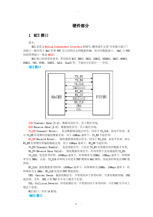
硬件部分1MII接口简介:MII是英文Medium Independent Interface的缩写,翻译成中文是“介质独立接口”,该接口一般应用于MAC层和PHY层之间的以太网数据传输,也可叫数据接口。
(MAC与PHY 间的管理接口一般是MDIO)MII接口的类型有很多,常用的有MII、RMII、SMII、SSMII、SSSMII、GMII、RGMII、SGMII、TBI、RTBI、XGMII、XAUI、XLAUI等。
下面对它们进行一一介绍。
MII接口TXD(Transmit Data)[3:0]:数据发送信号,共4根信号线;RXD(Receive Data)[3:0]:数据接收信号,共4根信号线;TX_ER(Transmit Error):发送数据错误提示信号,同步于TX_CLK,高电平有效,表示TX_ER有效期内传输的数据无效。
对于10Mbps速率下,TX_ER不起作用;RX_ER(Receive Error):接收数据错误提示信号,同步于RX_CLK,高电平有效,表示RX_ER有效期内传输的数据无效。
对于10Mbps速率下,RX_ER不起作用;TX_EN(Transmit Enable):发送使能信号,只有在TX_EN有效期内传的数据才有效;RX_DV(Reveive Data Valid):接收数据有效信号,作用类型于发送通道的TX_EN;TX_CLK:发送参考时钟,100Mbps速率下,时钟频率为25MHz,10Mbps速率下,时钟频率为2.5MHz。
注意,TX_CLK时钟的方向是从PHY侧指向MAC侧的,因此此时钟是由PHY提供的。
RX_CLK:接收数据参考时钟,100Mbps速率下,时钟频率为25MHz,10Mbps速率下,时钟频率为2.5MHz。
RX_CLK也是由PHY侧提供的。
CRS:Carrier Sense,载波侦测信号,不需要同步于参考时钟,只要有数据传输,CRS 就有效,另外,CRS只有PHY在半双工模式下有效;COL:Collision Detectd,冲突检测信号,不需要同步于参考时钟,只有PHY在半双工模式下有效。
- 1、下载文档前请自行甄别文档内容的完整性,平台不提供额外的编辑、内容补充、找答案等附加服务。
- 2、"仅部分预览"的文档,不可在线预览部分如存在完整性等问题,可反馈申请退款(可完整预览的文档不适用该条件!)。
- 3、如文档侵犯您的权益,请联系客服反馈,我们会尽快为您处理(人工客服工作时间:9:00-18:30)。
Copyright 2006 British Journal of Surgery Society Ltd Published by John Wiley & Sons Ltd
episodes independent of pH. The technique identifies the refluxate by changes in impedance produced by the presence of a bolus in the oesophagus, and this event can be classified as acid or non-acid by concomitant changes in intraluminal pH. Liquid boluses conduct better than the empty oesophagus, leading to a rapid decline in intraluminal impedance when the bolus enters the impedance measuring segment. Impedance returns to baseline once the bolus has exited the segment. Multiple impedance measuring segments mounted on the same catheter allow determination of the direction of bolus movement. Proximal to distal progression of impedance changes is indicative of swallowing, whereas a distal to proximal progression indicates reflux episodes. The pH component of MII–pH monitoring characterizes the chemical content of the refluxate. Impedance-detected
Original article
Combined multichannel intraluminal impedance–pH monitoring to select patients with persistent gastro-oesophageal reflux for laparoscopic Nissen fundoplication
British Journal of Surgery 2006; 93: 1483–1487
1484
I. Mainie, R. Tutuian, A. Agrawal, D. Adams and D. O. Castell
reflux episodes during which the pH drops to less than 4·0 are considered acid reflux episodes, whereas episodes during which the pH stays above 4·0 are traditionally considered to be non-acid5,6 . Symptoms that persist despite acid suppression therapy can be associated with either acid or non-acid gastro-oesophageal reflux, or not related to reflux episodes7 . There remains, however, a lack of data regarding outcome in patients in whom combined MII–pH monitoring has documented a positive symptom association with either acid or non-acid reflux while taking acid-suppressing agents. The aim of this study was to evaluate the clinical outcome of patients undergoing laparoscopic Nissen fundoplication for persistent symptoms on acid suppressive therapy, where MII-pH monitoring had shown a positive association between symptoms and reflux.
I. Mainie1 , R. Tutuian1 , A. Agrawal1 , D. Adams2 and D. O. Castell1
1 Division of Gastroenterology and Hepatology and 2 Department of Surgery, Medical University of South Carolina, Charleston, South Carolina, USA Correspondence to: Professor D. O. Castell, Medical University of South Carolina, 96 Jonathan Lucas Street, 210 Clinical Science Building, PO Box 250327, Charleston, South Carolina 29425, USA (e-mail: castell@)
Background: Combined multichannel intraluminal impedance-pH (MII-pH) monitoring detects gastro-
oesophageal reflux and identifies acid and non-acid reflux events. It can be used in patients with persistent symptoms on proton-pump inhibitor (PPI) therapy. The aim of this study was to assess laparoscopic Nissen fundoplication as a treatment for patients with persistent symptoms associated with reflux despite acid suppression documented by MII-pH monitoring. Method: A prospectively maintained database identified patients with persistent symptoms of gastrooesophageal reflux disease despite PPI therapy who had undergone MII-pH monitoring and this was cross-referenced with patients who had undergone fundoplication at this institution. Follow-up after fundoplication was by periodic telephone interview and review of clinical records. Results: Of 200 evaluated patients, 19 (14 female; mean age 40 (range 0.7–78) years) underwent laparoscopic Nissen fundoplication. Before surgery, 18 of 19 patients had a positive symptom index (at least half of symptoms associated with reflux) and one, a negative symptom index. After a mean follow-up of 14 (range 7–25) months, 16 of 17 (94 per cent) patients with a positive symptom index were asymptomatic or markedly improved (one patient was lost to follow-up). Persistent symptoms occurred in the patient with a negative symptom index, and one pቤተ መጻሕፍቲ ባይዱtient had recurrent symptoms after 9 months. Conclusion: Patients with a positive symptom index resistant to PPIs with non-acid or acid reflux demonstrated by MII-pH monitoring can be treated successfully by laparoscopic Nissen fundoplication.
Paper accepted 3 October 2006 Published online 19 October 2006 in Wiley InterScience (). DOI: 10.1002/bjs.5493
Introduction
Acid reflux is the primary mechanism responsible for the oesophageal manifestations of gastro-oesophageal reflux disease (GORD). Proton pump inhibitors (PPIs) are potent acid suppressors with healing rates for erosive oesophagitis of up to 93 per cent. Complete symptom control is, however, difficult to achieve, as shown in a large clinical trial in which 35–40 per cent of patients with GORD had persistent symptoms while taking PPIs1 . The surgical alternative to PPIs is fundoplication2,3 . Successful outcome after antireflux surgery can be predicted by an abnormal 24-h pH score, typical primary symptoms of GORD and a good response to acid suppression4 . Combined multichannel intraluminal impedance–pH (MII–pH) monitoring can detect reflux
