DDU18-4MC4中文资料
DDU18-8MC3中文资料

8-TAP, ECL-INTERFACEDFIXED DELAY LINE(SERIES DDU18)FEATURES PACKAGES• Eight equally spaced outputs• Fits in 400 mil 24-pin DIP socket• Input & outputs fully 100K-ECL interfaced & bufferedFUNCTIONAL DESCRIPTIONThe DDU18-series device is a 8-tap digitally buffered delay line. Thesignal input (IN) is reproduced at the outputs (T1-T8), shifted in time by anamount determined by the device dash number (See Table). For dashnumbers less than 16, the total delay of the line is measured from T1 toT8. The nominal tap-to-tap delay increment is given by one-seventh ofthe total delay, and the inherent delay from IN to T1 is nominally 2.0ns. For dash numbers greater than or equal to 16, the total delay of the line is measured from IN to T8. The nominal tap-to-tap delay incrementis given by one-eighth of this number.SERIES SPECIFICATIONS• Minimum input pulse width: 40% of total delay• Output rise time:2ns typical• Supply voltage:-5VDC ± 5%• Power dissipation: 500mw typical (no load)• Operating temperature: 0° to 85° C• Temp. coefficient of total delay: 100 PPM/°CVCC GNDIN T1T2T3T4Functional diagram for dash numbers < 16T5T6T7T8VCC GNDIN T1T2T3T4Functional diagram for dash numbers >= 16T5T6T7T8©1997 Data Delay Devicesdatadelaydevices, inc.®32419181313456789101112GNDT1T2T3GNDGNDT4T5T6T7T8INGNDVEEGNDGNDN/CT1T2T3GNDGNDT4T5T6T7T8INN/CN/CN/CN/CGNDVEEN/CN/CN/CN/CT10DDU18-xx DIPDDU18-xxM Military DIPDDU18-xxC3SMDDDU18-xxMC3Mil SMDPIN DESCRIPTIONSIN Signal InputT1-T8Tap OutputsVEE-5 VoltsGND GroundDASH NUMBER SPECIFICATIONSPartNumberTotalDelay (ns)Delay PerTap (ns)DDU18-4 3.5 ± 1.0 *0.5 ± 0.3DDU18-87.0 ± 1.0 * 1.0 ± 0.4DDU18-1210.5 ± 1.0 * 1.5 ± 0.4DDU18-1616 ± 1.0 2.0 ± 0.5DDU18-2020 ± 1.0 2.5 ± 1.0DDU18-2424 ± 1.2 3.0 ± 1.5DDU18-3232 ± 1.6 4.0 ± 2.0DDU18-4040 ± 2.0 5.0 ± 2.0DDU18-4848 ± 2.4 6.0 ± 2.0DDU18-5656 ± 2.87.0 ± 2.0DDU18-6464 ± 3.28.0 ± 2.0DDU18-7272 ± 3.69.0 ± 2.0DDU18-8080 ± 4.010.0 ± 2.5DDU18-100100 ± 5.012.5 ± 2.5DDU18-120120 ± 6.015.0 ± 3.0DDU18-160160 ± 8.020.0 ± 4.0DDU18-200200 ± 10.025.0 ± 5.0* Total delay is referenced to first tap outputInput to first tap = 2.0ns ± 1nsNOTE:Any dash number between 4 and 200not shown is also available.APPLICATION NOTESHIGH FREQUENCY RESPONSEThe DDU18 tolerances are guaranteed for input pulse widths and periods greater than those specified in the test conditions. Although the device will function properly for pulse widths as small as 40% of the total delay and periods as small as 80% of the total delay (for a symmetric input), the delays may deviate from their values at low frequency. However, for a given input condition, the deviation will be repeatable from pulse to pulse. Contact technical support at Data Delay Devices if your application requires device testing at a specific input condition.POWER SUPPLY BYPASSINGThe DDU18 relies on a stable power supply to produce repeatable delays within the stated tolerances. A 0.1uf capacitor from VEE to GND, located as close as possible to the VEE pin, is recommended. A wide VEE trace and a clean ground plane should be used.DEVICE SPECIFICATIONSTABLE 1: ABSOLUTE MAXIMUM RATINGSPARAMETER SYMBOL MIN MAX UNITS NOTES DC Supply Voltage V EE-7.00.3VInput Pin Voltage V IN V EE - 0.30.3VStorage Temperature T STRG-55150CLead Temperature T LEAD300C10 secTABLE 2: DC ELECTRICAL CHARACTERISTICS(0C to 85C)PARAMETER SYMBOL MIN TYP MAX UNITS NOTESHigh Level Output Voltage V OH-1.025-0.880V V IH = MAX,50Ω to -2V Low Level Output Voltage V OL-1.810-1.620V V IL = MIN, 50Ω to -2V High Level Input Voltage V IH-1.165-0.880VLow Level Input Voltage V IL-1.810-1.475VHigh Level Input Current I IH340µA V IH = MAXLow Level Input Current I IL0.5µA V IL = MINPACKAGE DIMENSIONSDDU18-xx (Commercial DIP)DDU18-xxM (Military DIP).015DDU18-xxC4 (Commercial SMD)DDU18-xxMC4 (Military SMD)DELAY LINE AUTOMATED TESTINGTEST CONDITIONSINPUT:OUTPUT:Ambient Temperature:25o C ± 3o C Load:50Ω to -2V Supply Voltage (Vcc):-5.0V ± 0.1V C load :5pf ± 10%Input Pulse:Standard 10KH ECLThreshold:(V OH + V OL ) / 2levels(Rising & Falling)Source Impedance:50Ω Max.Rise/Fall Time: 2.0 ns Max. (measuredbetween 20% and 80%)Pulse Width:PW IN = 1.5 x Total Delay Period:PER IN = 10 x Total DelayNOTE:The above conditions are for test only and do not in any way restrict the operation of the device.Test SetupTiming Diagram For TestingT RISET FALLPER INPW INT RISET FALL20%20%50%50%80%80%50%50%V IHV ILV OHV OLINPUT SIGNALOUTPUT SIGNAL。
轧机用四列圆柱滚子轴承

中华人民共和国机械行业标准滚动轴承JB/T 5389.1-1995轧机用四列圆柱滚子轴承代替JB/T 5389-91Four-row cylindrical roller bearings for Rolling Mill1 范围本标准规定了轧机用四列圆柱滚子轴承(以下简称轴承)的结构、代号、外形尺寸及技术条件。
本标准适用于轴承的制造、检验和设计选型与验收。
2 引用标准下列标准所包含的条文,通过在本标准中引用而构成为本标准的条文。
在标准出版时,所示版本均为有效。
所有标准都会被修订,使用本标准的各方应探讨使用下列标准最新版本的可能性。
GB/T 272-93 滚动轴承代号方法GB 307.2-84 滚动轴承公差的测量方法(GB/T 307.2-1995 滚动轴承测量和检验的原则及方法)GB 307.3-84 滚动轴承一般技术要求(GB/T 307.3-1996 滚动轴承通用技术规则)GB 3203-82 渗碳轴承钢技术条件GB 7811-87 滚动轴承参数符号ZB J11 020-89 滚动轴承及其商品零件检测规则ZB J36 001-86 滚动轴承零件渗碳热处理质量标准ZB J36 002-86 滚动轴承零件深层渗碳热处理质量标准JB 1255-91 高碳铬轴承钢滚动轴承零件热处理技术条件JB/T 2974-93 滚动轴承代号方法的补充规定JB/T 3016-91 滚动轴承包装钉板箱技术条件JB/T 3017-91 滚动轴承包装纸箱技术条件JB/T 3034-93 滚动轴承轴承油封防锈包装JB/T 3573-93 滚动轴承径向游隙的测量及评定方法JB/T 3574-91 滚动轴承产品标志3 符号和缩略语除下列符号外,本标准所引用的符号符合GB 7811的规定。
R : 内圈公称倒角r 1 : 外圈公称倒角r min : 内圈最小单向倒角尺寸r 1 min : 外圈最小单向倒角尺寸d1mpmax-d2mpmin : 同一轴承两内圈间,最大平均内径与最小平均内径之差d i : 内圈滚道公称直径 Δd i : 内圈滚道直径偏差Vd ip : 单一径向平面内,内圈滚道直径变动量 E : 内圈滚道公称宽度 L i : 内圈滚道直线度d imp -d imp ′: 内圈滚道两端平均直径之差Sd i : 内圈滚道素线对基准端面倾斜度的变动量 F w: : 滚子组内径4 结构型式FC 型-四列圆柱辊子轴承(见图1)FCD 型-双内圈四列圆柱辊子轴承(见图2)FCDP 型-外面带平挡圈的双内圈四列圆柱辊子轴承(见图3)5 代号5.1 代号的构成轴承代号由类型代号、尺寸代号和后置代号构成,其排列顺序如下:类型代号 尺寸代号 后置代号5.2 类型代号类型代号由大写拉丁字母组成,表示轴承的结构特征,见表1。
达涅利中文标准
标准代号:
5.900.016 共 11 页 第 3页
达涅利
Байду номын сангаас
铜和低合金铜(材料)
版次: 取代:
00
EN 1982:铜和铜合金。锭铁和铸件。 EN 12167:铜和铜合金。用于一般性用途的型面、矩形件 EN 12420:铜和铜合金。锻件 UNI 5649-1+FA1-90:铜-锻造铜制品-质量、需求与测试 UNI 5649-2+FA1-90:铜-锻造铜制品-质量、需求与测试 6- 责任 本款不适用 7–标准 7.1–特性 此处所指特性系指那些与测试样品和样件一致的特性 7.1.1- 铸件机械特性 此类产品目前尚未被列为达涅利机械标准。如果有特殊需求或要求,请参照以下标准: EN 1976、EN1982;可使用指定用于半成产品的同类材料。 7.1.2 – 铸件化学成份(%) 本款不适用 7.1.3- 铸件电学特性 本款不适用
硬度厚度mmcu模具表7172名称最小最大温度c抗张强度rmmpa02弹性强度rp02mpa延展度a5布氏测量值维氏测量值2026534519527525108095100195275含p压延模具en12167cudhph080en12167cw024ah080原为din1787sfcu原为uni56491cudhp所有所有2001451952026534326028025108095100260275255275200230245210230300180220180220压延模具din405002cuag01pf25encuag010ph080encw016ah080原为din17666cuag01p原为uni56492cuag01p所有所有400150151301452026534326028025108095100260275255275200230245210230300180220180220含ag辊压模具面板din405002cuag01pf25encuag010ph080encw016ah080原为din17666cuag01p原为uni56492cuag01p所有所有40015015130145718模具化学成份依照en1976en1976cudhp
海外规格仕样书第4版(中文)
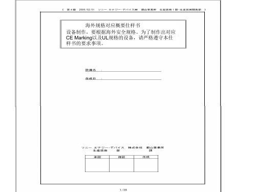
4.在机铭板上标示出以下内容 ・制造者名 ・制造年月 ・形式以及model编号 ・定格电源电压(电压、位相、周波数、最大负荷电流、etc) 在电源上不可以用「AC200V」表示,而要用「~200V」表示 ・气压(定格压力) ・原产地表示(MADE IN JAPAN等) 注)FA标准机铭板: 4—710—156—01(大—11) 带孔、by三立产业 EN60204 UL1740
8.盖子、马达框架、trans core、电装品筐体、以及接续管等的金属部, 如果和地线或金属接触,会导致和物品本身的导通。
EN60204、UL1740
7/28
要求事项
1.电源切断装置要使用得到认可的漏电断路器、自动断路器、线路保护器 EN60204、UL1740 2.主断路器的定格要遵循以下事项。 EN60204、UL1740 a)电流容量:最大负荷电流的115%以上,或者使用的导线的要求容许电流以下 (14配线以及电路——参照17) b)切断容量:在机器上使用的马达中,最大马达的 rotor rock电流+其他装置的 最大负荷电流以上 3.电力引入线(一次电源)要直接和断路器连接 EN60204、UL1740 4.电源切断装置遵循一下事项。 EN60204、UL1740 (a)安装把手,方便从外部操作 (b)把手的中心高度在0.6~1.9以内 (c)要有OFF锁定机能.(可以上锁的构造) (d)门关上时要有ON/OFF的明确指示 (e)ON/OFF可以用「O」也可以用「I」来表示 (f)接地导线以外所有的相要同时切断 (g)主断路器上如果没有OFF锁定机能,要在负荷侧设定带钥匙的主开关。
贵社 check
本社 check
备注
① 外 观 以 及 构 造 的 规 定
4/28
EN12184中文版本

NEN-EN12184:2009欧洲标准2009年9月ICS 11.180 10 取代EN12184:2006 电动轮椅、小型摩托车及其充电器-要求和试验方法本欧洲标准由欧洲标准化委员会于2009年8月27日批准。
CEN成员必须遵守CEN/CENELEC内部规则,其规定在国家标准没有任何变动的情况下制定出此欧洲标准。
最新的列表和有关这些国家标准的参考书目可向CEN管理中心或者任何CEN 成员申请获得。
这项欧洲标准有三种官方版本(英语版,法语版,德语版)。
由CEN成员翻译的并通知到CEN 管理中心的其他任何语言版本具有与官方版本同样的地位。
CEN成员是奥地利,比利时、保加利亚、塞浦路斯、捷克共和国,丹麦,爱沙尼亚,芬兰,法国,德国,希腊,匈牙利,冰岛,爱尔兰,意大利,拉脱维亚、立陶宛,卢森堡、马尔他、荷兰、挪威、波兰、葡萄牙、罗马尼亚,斯洛伐克,斯洛文尼亚,西班牙,瑞典,瑞士和英国的国家标准的主体。
管理中心:马尼克斯大街17号,B-1000 布鲁塞尔CEN国家成员保留任何形式、任何方式的开发权。
参考号:EN 12184:2009:E目录页数前言---------------------------------------------------------------------------------------------------------5介绍---------------------------------------------------------------------------------------------------------61.范围----------------------------------------------------------------------------------------------------72.引用标准----------------------------------------------------------------------------------------------73.术语及定义-----------------------------------------------------------------------------------------94.试验装置--------------------------------------------------------------------------------------------95.种类级别--------------------------------------------------------------------------------------------106.总体要求-------------------------------------------------------------------------------------------107.设计要求-------------------------------------------------------------------------------------------117.1脚支架,下肢支架和臂支架-----------------------------------------------------------------117.2充气轮胎---------------------------------------------------------------------------------------------117.3安装前骨盆支架-----------------------------------------------------------------------------------117.4在机动车中用作座椅的轮椅-------------------------------------------------------------------117.5刹车系统---------------------------------------------------------------------------------------------127.6飞轮装置---------------------------------------------------------------------------------------------127.7组件质量---------------------------------------------------------------------------------------------127.8电池外壳和电池盒--------------------------------------------------------------------------------127.9由乘员或者助手实行的操作-------------------------------------------------------------------137.10乘员操作的控制器-------------------------------------------------------------------------------137.11辅助控制组件,推手和手柄-------------------------------------------------------------------147.12充电连接器------------------------------------------------------------------------------------------148.性能要求-----------------------------------------------------------------------------------------------148.1总则-------------------------------------------------------------------------------------------------------148.2脚支架,下肢支撑组件和臂支架---------------------------------------------------------------148.21要求-----------------------------------------------------------------------------------------------------148.22测试-----------------------------------------------------------------------------------------------------158.3静态,冲击和疲劳强度-----------------------------------------------------------------------------15 8.3.1要求-----------------------------------------------------------------------------------------------------15 8.3.2测试-----------------------------------------------------------------------------------------------------15 8.4刹车系统-------------------------------------------------------------------------------------------------16 8.4.1总体要求-----------------------------------------------------------------------------------------------16 8.4.2测试------------------------------------------------------------------------------------------------------17 8.5操作力------------------------------------------------------------------------------------------------------18 8.5.1要求--------------------------------------------------------------------------------------------------------18 8.5.2测试----------------------------------------------------------------------------------------------------------19 8.6辅助控制组件,推手和手柄---------------------------------------------------------------------------19 8.6.1要求----------------------------------------------------------------------------------------------------------19 8.6.2测试----------------------------------------------------------------------------------------------------------20 8.7充电连接器---------------------------------------------------------------------------------------------------20 8.7.1要求-----------------------------------------------------------------------------------------------------------208.8驱动特性性能------------------------------------------------------------------------------------------------20 8.8.1总体-----------------------------------------------------------------------------------------------------------20 8..8.2攀爬最高安全斜坡的能力-----------------------------------------------------------------------------20 8.8.3地面不平坦性----------------------------------------------------------------------------------------------21 8.8.4最大下坡速度----------------------------------------------------------------------------------------------21 8.8.5动态稳定性-------------------------------------------------------------------------------------------------22 8.8.6越障-----------------------------------------------------------------------------------------------------------22 8.8.7静态稳定性-------------------------------------------------------------------------------------------------23 8.8.8最大速度-----------------------------------------------------------------------------------------------------23 8.8.9距离范围-----------------------------------------------------------------------------------------------------23 8.9表面温度--------------------------------------------------------------------------------------------------------23 8.10耐燃性----------------------------------------------------------------------------------------------------------24 8.10.1软垫复合部件----------------------------------------------------------------------------------------------24 8.10.2发泡材料----------------------------------------------------------------------------------------------------24 8.10.3其他部件----------------------------------------------------------------------------------------------------24 8.11气候试验---------------------------------------------------------------------------------------------24 8.12倾斜系统座椅调整--------------------------------------------------------------------------------24 8.12.1要求------------------------------------------------------------------------------------------------248.12.2测试方法------------------------------------------------------------------------------------------249.电气要求------------------------------------------------------------------------------------------------25 9.1总体要求---------------------------------------------------------------------------------------------25 9.2控制器开关要求------------------------------------------------------------------------------------25 9.3电源指示灯要求------------------------------------------------------------------------------------25 9.4电路保护要求---------------------------------------------------------------------------------------25 9.5电池充电器要求------------------------------------------------------------------------------------25 9.6充电指示器------------------------------------------------------------------------------------------26 10制造商提供的信息要求----------------------------------------------------------------------------26 10.1总则--------------------------------------------------------------------------------------------------26 10.2售前信息--------------------------------------------------------------------------------------------26 10.3用户信息--------------------------------------------------------------------------------------------27 10.4服务信息--------------------------------------------------------------------------------------------2810.5标签--------------------------------------------------------------------------------------------------2811.测试报告-----------------------------------------------------------------------------------------------2812 表格-----------------------------------------------------------------------------------------------------30 13图表------------------------------------------------------------------------------------------------------32 附录A(信息性的)质量超过100KG的测试假人的建议------------------------------------------36 A.1总则-----------------------------------------------------------------------------------------------------36 A.2结构-----------------------------------------------------------------------------------------------------36 A.3加速器安装--------------------------------------------------------------------------------------------36 A.4设计目的-----------------------------------------------------------------------------------------------37 附录B(信息性的)电动轮椅尺寸和操作空间的建议-----------------------------------------------45 B.1具体尺寸-----------------------------------------------------------------------------------------------45 B.1.1准备使用时的尺寸--------------------------------------------------------------------------------45B.1.3离地间隙--------------------------------------------------------------------------------------------45 B.2操作空间--------------------------------------------------------------------------------------------------45 B.2.1转向直径-----------------------------------------------------------------------------------------------45 B2.2换向宽度------------------------------------------------------------------------------------------------45 B.3速度设置-------------------------------------------------------------------------------------------------45 附录C(信息性的)推荐设计特点----------------------------------------------------------------------47C.1引言-------------------------------------------------------------------------------------------------------47 C.2总体建议-------------------------------------------------------------------------------------------------47 C.2.1防倾斜装置--------------------------------------------------------------------------------------------47 C.2.2组件质量-----------------------------------------------------------------------------------------------47 C.2.3配件和工具--------------------------------------------------------------------------------------------47 C.2.4轮胎-----------------------------------------------------------------------------------------------------47 C.2.5轮胎充气方法-----------------------------------------------------------------------------------------47 C.2.6表面温度--------------------------------------------------------------------------------------------- -47 C.2.7乘员坐入或者离开轮椅------------------------------------------------------------------------ ----48 C.2.8耐尿失禁污染-----------------------------------------------------------------------------------------48 C.2.9最大安全斜坡指示-----------------------------------------------------------------------------------48 C.2.10镜子---------------------------------------------------------------------------------------------------48 C.2.11头部支撑----------------------------------------------------------------------------------------------48 C.2.12意外释放刹车制动器和飞轮装置---------------------------------------------------------------48 C.3性能特征建议-------------------------------------------------------------------------------------------49 C.3.1电气故障的指示--------------------------------------------------------------------------------------49 C.3.2电池和电池盒-----------------------------------------------------------------------------------------49 C.3.3照明-----------------------------------------------------------------------------------------------------49 C.3.4控制机能反馈-----------------------------------------------------------------------------------------49 C.3.5飞轮报警-----------------------------------------------------------------------------------------------49 C.3.6最大速度-----------------------------------------------------------------------------------------------49 附录D(信息性的)推荐的座椅设计---------------------------------------------------------------------50 附录E(信息性的)操作力-----------------------------------------------------------------------------------51 E.1建议--------------------------------------------------------------------------------------------------------51 E.1.1推手力--------------------------------------------------------------------------------------------------51 E.1.2轮圈力--------------------------------------------------------------------------------------------------51 E.2轮圈电助力轮椅的操作测试-------------------------------------------------------------------------51 附录F(信息性的)相对于原先版本EN12184的技术改变--------------------------------------52 F.1第一版本(1999)与第二版本(2006)的技术改变------------------------------------------52 F.2相对于第二版本(2006)的技术改变-------------------------------------------------------------53 附录ZA(信息性的)此欧洲标准与1993年6月14日颁布的关于医疗设备的理事会指令93/42/EEC中的基本要求的之间的关系。
湛金斯4式3.979英寸4筒燃油发动机商品说明书

APPLICATION: Crawlers: MF 300 (LF21577);Wheel Loaders: MF 22C (LF22663); 33 (LF21578, LF21580);QTY ITEM # DESCRIPTION LETTERED ITEMSINCLUDED IN KIT1 974125 In-Frame Kit (Late 3 Ring Upgrade Pistons) (1) I1 975125 Out-of-Frame Kit (Late 3 Ring Upgrade Pistons) (1) O4 171118 Sleeve & Piston Assembly (4 Ring Piston) (1)4 171379 Sleeve & Piston Assembly (Late 3 Ring Upgrade Piston) (1) O I4 171198 Piston Assembly (4 Ring Piston) (1) (2)4 171228 Piston Assembly (Late 3 Ring Upgrade Piston) (1) (3)4 171132 Cylinder Liner (Finished / Fire Dam / 4.1025" OD)4 171217 Cylinder Liner (Semi-Finished / Fire Dam / 4.1045" OD) (4)4 171468 005 Liner Shim4 171477 Piston Ring Set, Early 4 Ring (3-3/32 1-3/16)4 171192 Piston Ring Set, Late 4 Ring (3-3/32 1-1/4) "Fits 171198"4 171265 Piston Ring Set, 3 Ring Upgrade (2-2.5MM 1-5MM)4 271151 STD Rod Bearing O I4 271152 .010 Rod Bearing4 271153 .020 Rod Bearing4 271154 .030 Rod Bearing "Additional Sizes (5)"1 271161 STD Main Set, wo/Thrust Washers O I1 271162 .010 Main Set, wo/Thrust Washers1 271163 .020 Main Set, wo/Thrust Washers1 271164 .030 Main Set, wo/Thrust Washers "Additional Sizes (6)"1 271119 STD Thrust Washer Set (Offset Lug) O I1 271125 .007 Thrust Washer Set (Offset Lug)1 271126 .010 Thrust Washer Set (Offset Lug)1 371115 Head Gasket Set O I1 371116 Head Gasket1 371117 Valve Cover Gasket8 371143 Valve Seal4 371239 Nozzle Dust Seal "Not In Gasket Sets Or Kits"1 1 1 1 371292 371149 371235 371167 Lower Gasket Set wo/Seals Timing Cover Gasket Fuel Line Seal Kit (23 Seals & Washers) "Not In Gkt Sets" Pan Gasket Set (Also Includes 6 Oil Flange Gaskets) O OI1 371146 Front Crank Seal (Viton Lip Type) (7) O1 371161 Rear Crank Seal Kit, Thru 248UA123423 (Rope Type) (8) O1 371186 Rear Seal & Housing Kit, Thru 248UA123423 (Rope Type) (8)1 371145 Rear Crank Seal, After 248UA123423 (Viton Lip Type) (9) O1 771159 Rear Block Bridge Piece4 271176 Pin Bushing (1.375" Pin)1 271127 Cam Bearing (Finished ID)8 771151 Connecting Rod Bolt 8 771148 Connecting Rod Nut1 771321 Head Stud/Bolt & Nut Kit (4 Studs / 18 Bolts)(1)Late 3 Ring Pistons Replace 4 Ring, Replace In Sets, DO NOT MIX (2)Untopped Piston Assembly - 171475(3)Untopped Piston Assembly - 171476 (4).020 Oversize Semi-Finished Liner - 171478(5)Rod Bearings: .040 - 271155 / .050 - 271156 / .060 - 271157 (6)Main Bearings: .040 - 271165 / .050 - 271166 / .060 - 271167APPLICATION: Crawlers: MF 300 (LF21577);Wheel Loaders: MF 22C (LF22663); 33 (LF21578, LF21580);QTY ITEM # DESCRIPTION LETTERED ITEMSINCLUDED IN KIT1 979516 Camshaft Kit C1 979143 Valve Train Kit V1 979139 Valve Train Kit, w/Guides V1 571122 Camshaft "Cam Bolt Lock Plate - 571162" C1 271249 Camshaft Thrust Washer (1.750 X 2.873 X .217)8 571123 Tappet C4 4 471123 471128 STD Exhaust Valve (45º / Bi-Metal) (10) STD Intake Valve (45º / Alloy / Chromed Stem) (11) V V V V4 471132 Exhaust Guide: Service Repair or 1985 & Up V4 471131 Intake Guide: Service Repair or 1985 & Up V8 471134 Outer Valve Spring (8 Coils / 2.500" Free Length) V V8 471133 Inner Valve Spring (9 Coils / 2.000" Free Length) V V8 471219 Spring Seat, Integral Guides "With Service Guides - 471229"8 471222 Spring Retainer16 471146 Keeper (Half) V V4 471111 Exhaust Seat (1.248 x 1.681 x .374 Stepped Top)4 471113 Intake Seat (1.594 x 2.020 x .281)4 471224 LH Rocker Arm (Adj Screw & Lock Nut Not Included) (12)4 471225 RH Rocker Arm (Adj Screw & Lock Nut Not Included) (12)1 471227 Rocker Arm Shaft (13) "Includes 471176 Plugs"1 571165 Cam Gear (Steel / 56 Teeth)1 571113 Crank Gear (28 Teeth) 1 571163 Idler Gear (Steel / 63T)2 571144 Idler Gear Bushing1 571145 Idler Gear Hub8 571117 Push Rod1 671112 Oil Pump1 671134 Oil Pump Idler Gear1 571124 Idler Gear Bushing1 671148 Relief Valve Assembly (Engines w/LH Oil Filter Only)1 771129 Crank Kit, Thru 248UA123423 (Spline Nose / Rope Seal)1 771132 Crank Kit, After 248UA123423 (Spline Nose / Lip Seal)4 771154 Connecting Rod (1.375" Pin)1 771264 Cylinder Head Assembly (Includes Valves & Springs)1 771286 Expansion Plug Kit (Includes 19 Plugs For Head & Block)1 871138 Thermostat (2.125" / Bypass)1 871229 Water Pump wo/Pulley: Except LF226631 871228 Block Heater (1.250")1 871225 Fuel Pump, Early (2 Bolt/Horizontal Diaphram)1 871152 Fuel Pump, Late (4 Bolt)(10)Oversizes: .003 - 471271 / .015 - 471272 / .030 - 471273 (11)Oversizes: .003 - 471274 / .015 - 471275 / .030 - 471276。
B18系列产品说明书

*(XXX)CO
4
MC/AC
4
1/2" [13] & 3/4" [19]
Attaches to 1/8" [3] through 1/4" [6] flange.
4
1" [25]
4
MC/AC
4
1/2" [13] & 3/4" [19]
other purpose.
NOTE: All load ratings are for static conditions and do not account for dynamic loading such as wind, water or seismic loads, unless otherwise noted.
Pentair, CADDY, ERICO CADWELD, ERICO CRITEC, ERICO, ERIFLEX, and LENTON are owned by Pentair or its global affiliates. All other trademarks are the property of their respective owners. Pentair reserves the right to change specifications without prior notice.
CADDY B18 series with threaded rod going through both
the B18 and the box, this single support is appropriate.
MC-4系列说明书 (1)

• 使检测仪进入校准操作,按住 C,检测仪先完成OFF倒计时,继续按住C,显示屏暂时关闭,
然后出现CAL倒计时。CAL倒计时完成后放开C。
• 开启背景照明灯,按 C。 • 确认已锁定的报警,按 C。
5
GasAlertMicroClip 气体检测仪操作指南
校准
步骤
1. 在清洁空气环境下,按住C直至屏幕出 现OFF倒计时,检测仪暂时关闭后时继 续按住C。
H2S: 0至100 ppm (1 ppm 增量) CO: 0至500 ppm (1 ppm 增量) O2: 0至30.0% vol. (0.1% vol.增量) 可燃气体(LEL): 0至100% (1%增量) 传感器类型: H2S, CO, O2:单一插拔式电化学电池 可燃气体:插拔式催化珠 氧气检测原理:毛细管控制浓度传感器
2. 检测仪重新启动,屏幕显示CAL倒计 时,按住C直至倒计时结束并进入校准 状态。
3.
闪烁,此时检测仪开始将
所有传感器归零,并对氧气传感器进
行校准。如自动归零失败,则不能进
行跨度调整。自动归零完成后,屏幕
显示APPLY GAS(施加标气)。
显示
步骤
4. 接通标气气瓶且以250-500ml/min流
正常关机:
• 四次“ 嘟” 音和四次闪光 • 震动报警器暂时性启动
GasAlertMicroClip 报警
屏幕显示
注意 报警方式可设置成锁定模式或非锁定模式。进入GasAlertMicroClip菜单的警报锁定选项可确认设定。地方法规有可能要求检测仪须使 用锁定报警模式。 如果检测仪设置为静音模式,在报警条件出现时只有震动报警启动(听觉报警和视觉报警均被关闭);如检测仪设置为IR静音模式, 则视觉报警和震动报警启动(听觉报警关闭)。 背景灯在任何报警条件下均启动。
MG18-420交流电牵引采煤机说明书

H113202 左离合组件------------------------------------------------------------- 46 H1141 左行走部------------------------------------------------------------ 48 H114101 输入轴组件------------------------------------------------------------ 50 H114101 驱动轮轴组件---------------------------------------------------------- 52 H114103 行走轮组件------------------------------------------------------------- 54 H1142 右行走部------------------------------------------------------------------ 56 H1102 液压及集中注油系统---------------------------------------------------- 58 H110201 集中注油块------------------------------------------------------------ 62 H110203 阀组------------------------------------------------------------ 64 H1103 冷却喷雾系统------------------------------------------------------------- 67 H110301 总分水块---------------------------------------------------------------- 69 H110302 右分水块- -------------------------------------------------------------- 71 H110303 回水块---------------------------------------------------------------- 73 H110304 分水块------------------------------------------------------------ 75 H110305 总回水块------------------------------------------------------------ 77 H110306 左分水块--------------------------------------------------------------- 79 H110307 减压阀组件------------------------------------------------------------- 81 H1101 电控部 ------------------------------------------------------------------ 83 H110101 高压控制箱 ------------------------------------------------------------ 85 H110192 按钮组件------------------------------------------------------------ 91 H110193 隔离开关组件------------------------------------------------------- 93
低压电气的使用类别
什么是低压开关设备和控制设备的使用类别。
发布日期:2014-06-04 浏览次数:4核心提示:什么是低压开关设备和控制设备的使用类别。
我们在选择低压电器的额定工作电流时,除了要考虑额定电压U、额定频率、额定工作制什么是低压开关设备和控制设备的使用类别。
我们在选择低压电器的额定工作电流时,除了要考虑额定电压U、额定频率、额定工作制等参数外,还必须要考虑负载的使用类别,同一个低压电器在不同的负载类别下的额定工作电流是不同的,下表给出了不同负载类别的含义。
电流种类类别典型用途有关产品标准交流 AC-1AC-2AC-3AC-4AC-5aAC-5bAC-6aAC-6bAC-7aAC-7bAC-8aAC-8b 无感或微感负载、电阻炉绕线式电动机的起动、分断鼠笼型异步电动机的起动,运转中分断鼠笼型异步电动机的起动、反接制动与反向运转、点动控制放电灯的通断白炽灯的通断变压器通断电容器组的通断家用及类似用途的微感负载家用电动机负载具有过载继电器手动复位的密封制冷压缩机中的电动机控制具有过载继电器自动复位的密封制冷压缩机中的电动机 GB 14048.4AC-11AC-12AC-13AC-14AC-15 控制交流电磁铁负载控制电阻性负载和发光二极管隔离的固态负载控制变压器隔离的固态负载控制小容量交流电磁铁负载(不大于72VA)控制交流电磁铁负载(大于72VA) GB 14048.5AC-20AC-21AC-22AC-23 无载条件下“闭合”和“断开”电路通断电阻负载,包括通断适中的负载通断电阻电感混合负载,包括通断适中的负载通断电动机负载或其它高电感负载 GB 14048.3交流和直流 AB 无额定短时耐受电流要求的电路保护,具有额定短时耐受电流要求的电路保护 GB 14048.2直流DC-1DC-3DC-5DC-6 无感或微感负载、电阻炉并励电动机的起动、反接制动与反向运转1)、点动2)、电动机的动态分断串励电动机的起动、反接制动与反向运转1)、点动2)、电动机的动态分断白炽灯的通断 GB 14048.4DC-12DC-13DC-14 控制电阻性负载和发光二极管隔离的因态负载控制直流电磁铁负载控制电路中有经济电阻的直流电磁铁负载 GB 14048.5DC-20DC-21DC-22DC-23 无载条件下“闭合”和“断开”电路通断电阻负载,包括通适中的过载通断电阻电感混合负载,包括通断适中的负载(例如并励电机)通断高电感负载(例如串励电动机) GB 14048.3接触器的使用类别及典型负载1. 使用类别见下表使用类别代号典型用途举例AC-1 无感或微感负载、电阻炉AC-2 绕线式感应电动机的起动、分断AC-3 笼型感应电动机的起动、运转中分断AC-4 笼型感应电动机的起动、反接制动或反向运转、点动AC-5a 放电灯的通断AC-5b 白炽灯的通断AC-6a 变压器的通断AC-6b 电容器组的通断AC-7a 家用电器和类似用途的低感负载AC-7b 家用的电动机负载AC-8a 具有手动复位过载脱扣器的密封制冷压缩机中的电动机AC-8b 具有自动复位过载脱扣器的密封制冷压缩机中的电动机2. 典型负载不同的用电设备其负载性质和通断过程的电流变化相差很大,因此对接触器的要求也有所不同,常用的负载有以下数种:2.1 电热元件负载对电热元件负载中用的线绕电阻元件,其接通电流可达额定电流的1.4倍,例如用于室内供暖,电烘箱及电热空调等设备。
RC4 中文操作手册

手册引导内容提要1介绍1.1手册结构1.2补充文件1.3操作手册使用人群1.4手册中使用的信号和警示1.5使用的方式和缩写1.6版本附件2设备描述2.1目的2.2潜在的危险3总述3.1电源3.2外加24VDC3.3使用的电缆型号3.4安全须知3.4.1Congrav RC-4使用安全须知3.4.2安装安全须知3.4.3接线安全须知3.4.4使用和操作安全须知4硬件描述4.1Congrav RC-4:类型4.2Congrav RC-4A:显示和按键4.2.1集成按键及其功能4.2.2显示和功能组成4.3参数更改4.3.1数字输入4.3.2固定参数设置的选择4.3.3如果….,更改参数不被接受4.4Congrav RC-4B:4.5Congrav RC-4的插卡槽4.5.1现场的可能连线4.6Congrav RC-4的基本功能4.6.1插入卡RC4-MSIO4.6.1.1XS1.1:与主计算机的连接4.6.1.2XS1.2:与ISC现场总线的连接4.6.1.3XS1.3:与调试解调器和工控电脑的连接4.7Congrav RC-4的选项卡4.7.1CDIO插入卡4.7.2DIOP插入卡4.7.2.1输入输出模式-数字式RC-4的终端功能4.7.3ANOP插入卡4.7.3.1输入输出模式-模拟式RC-4的终端功能4.7.4Profibus模式5调试5.1安装5.2调试,Congrav RC-4的开机5.3Congrav RC-4:软件升级5.4ISC-CM:软件升级6菜单页F100安装结构6.1F110:安装模式6.2模拟结构6.3F120:主计算机操作6.4F130:显示内容改变6.5连锁停机6.6时间和日期6.7F150:配方处理6.7.1设定值斜线,设定值阈值6.7.2调试操作7F200:打印机结构,内存值重设7.1打印功能7.2F210:如何清除记忆内容8F300:设定值输入和选择8.1安装设定值8.2加料器设定值8.2.1`设定值的模拟控制8.2.2设定值斜线,设定值阈值(菜单页F150)8.3选项8.4F310:滞后时间8.5报警停机9F400:安装的实际值,总产量重设9.1F430:总产量重设10单台加料器操作10.1加料器页的抬头10.2Kxx0:加料器控制10.3操作功能10.3.1开机5410.3.2停机5410.3.3报警重设10.3.4补料5510.3.5删除5510.3.6开始试样10.3.7开始去皮10.3.8右侧行实际值的显示10.4Kxx1:产品参数10.4.1自动去皮10.4.2检查最大输出10.4.3堆积密度10.4.4体积最大输出10.4.5十进制转换10.4.5.1十进制转换的设置10.4.6模式5910.4.6.1失重式加料(GF)10.4.6.2体积式控制(VR)10.4.6.3体积式设置(VS)10.4.6.4排料(DI)10.4.6.5检查最大输出(CM)10.4.6.6重量式排料(GD)10.4.6.7体积式加料(VF)10.4.6.8测量(M)10.4.6.9运行过程中GF和VF模式转换10.5Kxx2:控制参数10.5.1PID控制的设置10.5.1.1控制成套配合10.5.1.2重量式计算最大输出10.5.1.2.1CM值的存储11F500:报警报告和开机条件11.1报警报告11.2缺省的开机条件11.3系列驱动控制操作的错误代码11.3.1系列变频器11.3.2振动放大器控制器ISC-VC 11.4Kxx5:报警结构12硬件结构12.1 Kxx8:ISC-CM(-A)的硬件结构12.1.1 速度输入12.1.2 传感器(重量读取)的结构12.1.3 驱动控制器12.1.4 ISC-CM-A模拟输入输出的结构12.1.4.1 ISC-CM-A上单台控制的选项12.1.4.2 Kxx8:模拟输入12.1.4.3 Kxx8:模拟输出12.2 ANOP模拟输入输出的结构12.2.1 安装控制和安装的实际值12.2.1.1 菜单页F190的参数12.2.2 ANOP的组分功能12.2.2.1 模拟输入:模拟单台控制12.2.2.2 模拟输出:总操纵量或实际值12.2.2.2.1 模拟输出信号范围的定义12.3 CDIO的数字输入输出12.4 DIOP的数字输入输出12.4.1 DIOP:功能描述12.5 ISC现场总线机构12.5.1 如果构建总线通讯12.5.2 总线通讯的关闭12.6 调试解调器的机构12.7 主计算机操作机构12.7.1 MISO卡上的主计算机接口12.7.2 Profibus DP操作结构12.7.3 以太网接口的结构13校正程序13.1加料器参数13.2加料器参数功能解释13.2.1CP02-加料范围13.2.2CP04-欠载13.2.3CP03-最大输出量13.2.4CP05-过载13.2.5CP06-粗去皮13.2.6CP07-平均重量取数13.2.7CP08-总产量累计分值13.2.8CP09-最小速度13.2.9CP010-最大速度13.2.10CP11-控制偏差13.2.11CP12-报警停机滞后时间13.2.12CP13-联锁类型13.2.13CP14-实际值指示13.2.14CP15-杠杆臂值13.2.15CP16-料斗内容13.2.16CP17-最小补料料位13.2.17CP18-最大补料料位13.2.18CP19-Window/K1/滤波IDL/F, AED 13.2.19CP20-数字速度13.2.19.1标准速度监控13.2.19.2FlexWall-Plus加料器的运动监控13.2.19.3数字式速度取数13.2.19.4推荐输入13.2.20CP21-最大补料时间13.2.21CP22-补料优化13.2.22CP23-稳定时间13.2.23CP24-测样时间13.2.24CP25-防振(A V)切断时间13.2.25CP26-PID控制器接近时间13.2.26CP27-控制器自动化13.2.26.1控制器自动化13.2.26.2开机自动化13.2.26.2.1重复的开机自动化13.2.26.2.2总体开机自动化13.2.27CP28-滤波限制13.2.28CP29-实际值的接纳13.2.29CP30-总操纵量的接纳13.2.30CP31-体积控制(VR)实际值的接纳13.2.31CP32-开机滞后时间13.2.32CP33-称重桥(LWB)的长度13.2.33CP34-重量测试值(WTV)13.2.34CP35-摄取(AP)13.2.35CP36-自动去皮范围13.2.36CP37-无负载时间自动去皮13.2.37CP38-有比例的皮带速度13.2.38CP39-皮带长度13.2.39CP40-dead time way13.3附加参数13.3.1AP01-05 校正13.3.2AP11-可用的称重范围13.3.3AP12-drop out13.3.4AP13-速度模式13.3.5AP14-滑动影响13.3.6AP15-滑动值13.3.7AP16-速度接纳性13.3.8AP17-无负载时间13.3.9AP18-AT时间13.3.10AP19-驱动控制2最小13.3.11AP20-驱动控制2最大14硬件测试功能14.1F140:输入输出测试-外围(安装)14.2Kxx3:输入输出状态显示-外围14.3Kxx4:测试功能和模拟14.3.1模拟模式14.3.2输入输出测试(加料器)15名词解释附件11915.1技术数据15.2电磁兼容性15.3零配件清单15.4可能显示的模式清单15.5菜单页清单插图表图4-1:Congrav RC-4后部视图图4-2:Congrav RC-4后部视图(带ProfiBus模式)1 总介绍1.1手册的结构现有的操作手册包括:RC-4的:●技术操作和●RC-4 HGC软件(其版本请参见封页)按照下列顺序,每章独立描述一个完整的主题:●设备的描述●使用特性●硬件执行●硬件功能定义●操作●软件描述●参数描述和●结构例举1.2附加文件●ISC系统的描述●ISC-CM,ISC-FC和ISC-VC的技术手册●相应主计算机程序手册1.3操作手册所适用的人群操作手册适用于以下两组人群:●经过授权和培训过的专业技术人员来进行安装和其它电气工作。
WDZ-418阻抗保护技术说明书

第十二章WDZ-418线路阻抗保护测控装置1. 产品用途及特点WDZ-418线路阻抗保护测控装置(以下简称装置)主要为6KV和10KV小电流接地系统中的线路多相短路提供保护,同时对该线路进行测控。
完备的保护功能:●相间阻抗保护●过电流保护●PT断线告警●负序过流一段保护●负序过流二段保护●故障录波测控功能:●10路遥信开入采集、装置内部遥信、事故遥信●断路器遥控跳、合●遥测量:三相电压,三相电流,P,Q,功率因数,频率●2路脉冲量输入实现外部电度表自动抄表●内嵌高精度智能电度表,可节省外部电度表(选配)●1路4~20mA直流模拟量输出,替代变送器作为DCS测量接口(选配)通讯功能:●智能通讯卡:常规配置高速RS485现场总线,通讯速率可达115.2Kbps,并支持双网。
也可选配工业以太网●RS485现场总线支持光纤通讯(选配)本装置具有如下特点:●采用先进的32位嵌入式微处理器,多CPU结构●汉字液晶显示、操作简便直观●用串行EEPROM存放保护定值、运行及故障信息●可预先设定5套定值适应各种运行工况●SOE和自检报告失电自动保存●软、硬件冗余设计,抗干扰性能强●完善的软、硬件自检,二级看门狗●全密封嵌入式机箱设计,体积小,重量轻,可直接安装在开关柜上●安全可靠的高速现场总线技术,支持双网和光纤接口●完善、灵活的保护功能,全面、准确、可靠的测控功能●DCS测量接口(4~20mA模拟量输出)2. 主要保护功能及原理本保护采用一段式相间阻抗保护,具有圆形动作特性,圆的中心位于坐标原点,以确保对母线出线处的短路故障,并且短路回路中电阻占主要数值时的灵敏度。
为避免电压回路发生故障时,阻抗保护误动作,本保护增加一段式过流保护起到电流闭锁作用,并且在阻抗保护故障或者退出时,起到过流保护作用。
保护原理框图见图12.1。
Z ab <Z zd Z ca <Z zdI a >I glI c >I glKI1(阻抗保护退出)I a >I glI c >I glKI1(阻抗保护退出)I a <I glI c <I glZ bc <Z zd Z ab <Z zd Z ca <Z zd Z bc <Z zd I 2>I 21dzI 2>I 22dz图12.1 WDZ-418保护原理框图2.1.相间阻抗保护其动作判据为: I max =max (I a ,I c )Z min =min(Zab,Zbc,Zca)Imax >IglZmin <Zzdt>tzd开入1未闭合式中,Imax :A、C相电流(Ia,Ic)最大值(A)Zab:A、B相间的测量阻抗(Ω)Zbc:B、C相间的测量阻抗(Ω)Zca:C、A相间的测量阻抗(Ω)Zmin :测量阻抗(Zab,Zbc,Zca)最小值(Ω)Zzd:阻抗保护定值(Ω)tzd:整定的阻抗保护动作时间(s)Igl:过流保护动作定值(A)开入1定义为阻抗保护推出,当开入1闭合时,阻抗保护退出。
美国机器与工具公司4英寸垃圾泵维修部件手册说明书

Please read and save this Repair Parts Manual. Read this manual and the General Operating Instructions carefully before attempting to assemble, install, operate or maintain the product described. Protect yourself and others by observing all safety information. The Safety Instructions are contained in the General Operating Instructions. Failure to comply with the safety instructions accompanying this product could result in personal injury and/or property damage! Retain instructions for future reference. AMT reserves the right to discontinue any model or change specifications at any time without incurring any obligation.©2010 American Machine & Tool Co., Inc. of PA, A Subsidiary of The Gorman-Rupp Company, All Rights Reserved.Periodic m aintenance and inspection is required on all pum ps to insure proper operation. Unit m ust be clear of debris and sedim ent. Inspect for leaks andloose bolts. Failure to do so voids warranty.4-INCH TRASH PUMPRefer to pump manual 1808-633-00 for General Operating and Safety Instructions.DescriptionThis trash pump is a heavy duty, centrifugal, engine-driven, self-priming (to 20 ft. lift after initially filling casing with liquid), portable unit. Pump is equipped with precision lapped mechanical seal to reduce the likelihood of leakage, and a clog-resistant impeller capable of handling solids up to 2" diameter. Units are used to handle water containing stones, sticks, mud and other solids (up to 25% by volume). O-ring sealed flange connections facilitate easy removal of suction and discharge lines. Handles liquids from 40º to 180º F (4ºto 82º C). For use with nonflammable fluids compatible with pump component materials.All models come standard with manual recoil starter, E-start models 3993-96, 3993-D6 and 3994-96 feature in addition a 12V electric starter switch and cables. 5" W x 7¾" L x 5" H battery holder included. (Battery not included; obtain 12V, 32 amp hour battery from local lawn and garden shop).Pump and engine are mounted on rugged transport dolly with fully pneumatic 16" ball bearing wheels. Proper weight distribution ensures easy portability, yet pump is stable when operating. Four position discharge manifold provides a choice in placing hose.SpecificationsSuction inlet...........4" MNPT Discharge outlet........4" MNPT Engine4210-96....1 CY B&S Vanguard 3993-96*...2 CY B&S Vanguard 3994-96*........Honda GX390 3993-D6*...Yanmar Diesel L100 *E-Start ModelsBasic construction.Aluminum with cast iron volute, impeller, wear-plates and discharge manifold;silicon carbide seal. Battery.....12 Volt, type No. 9A1, 32 amp hour (not supplied) Battery tray*..5" W x 7¾" L x 5" H (*E-Start Models)UnpackingRefer to Repair Parts Illustration and Repair Parts List to aid in identifying parts. Unpack and separate all pump components from container, making sure all parts are accounted for. Packages should contain:1.Pump and engine completelyassembled on wheel kit.2.Battery tray (Ref. No. 37) andbattery tray hardware (E-startmodels only).3.4" NPT Nipple Pack and Strainer.ASSEMBLY (Refer to Figure 2)1.Remove pump from packaging.2.Stand pump carefully on pump end.Reposition handle (Ref. No. 32) (asshown in Figure 2) facing outwardsby removing and replacing existinghandle fasteners.3.Electric Start Models Only: Attachbattery tray (Ref. No. 37) to leftengine rail using fasteners used withhandle. Install a 12 volt type no. 9A1garden tractor battery 32 amp hourrating, approx. size 7¾" L x 5" W x6" H (not included) onto battery tray.Using hardware included with pump,insert hook bolts through battery trayholes, thread facing up. Attachbattery box holddown bar acrossbattery and thread wing nuts ontohook bolts. Refer to engine manualfor proper wiring instructions.MaintenanceMECHANICAL SEAL REPLACEMENTRefer to Figures 1 and 2NOTE: Always replace the seal seat(Ref. No. 8), seal head (Ref. No. 9) andshaft sleeve (Ref. No. 10) to ensureproper mating of mechanical sealcomponents!Figure 11.Unthread cap screws (Ref. No. 30)and remove casing (Ref. No. 18)and casing seal (Ref. No. 7) fromadapter (Ref. No. 6).2.Unthread screws (Ref. No. 14) andremove volute (Ref. No. 13) fromadapter.3.Unscrew impeller (Ref. No. 12)from the engine shaft. Remove theimpeller shim (Ref. No. 11), shaftsleeve and seal head from engineshaft. Use a rubber mallet or softblock of wood to loosen impeller.Turn it counterclockwise.Disconnectspark plug wireand battery toprevent accidental starting.3993-251-00 03/20114.Unthread cap screws (Ref. No. 4)and remove the adapter from theengine mounting face.5.Push seal seat from the adapterrecess with a screwdriver.6.Clean the adapter recess beforeinserting a new seal seat.7.Carefully wipe the polishedsurface of the new seal seat witha clean cloth.8.Wet the rubber portion of the sealseat with a light coating of soapywater.9.Press the new seal seat squarelyinto the cavity in the adapter. Ifthe seal seat does not presssquarely into the cavity, it can beadjusted in place by pushing on itwith a piece of pipe. Always use apiece of cardboard between thepipe and the seal seat to avoidscratching the seal seat. (This is alapped surface and must behandled very carefully).10.After the seal seat is in place,ensure that it is clean and has notbeen marred.ing a clean cloth, wipe the shaftand make certain that it isperfectly clean.12.Secure the adapter on the enginemounting face.NOTE: Tighten cap screws EVENLY to avoid cocking rabbet on engine mounting face.13.Apply a light coating of soapywater to the inside rubber portionof seal head and slide onto theshaft sleeve. Slip the shaft sleevewith seal head onto the engineshaft.IMPORTANT: Before installing new shaft sleeve, apply a bead of non-hardening, pliable sealant (such as Permatex® Form-A-Gasket® No. 2) to motor shaft shoulder.Do not touch orwipe the face of the polished part of the seal head.14.Replace any impeller shimsremoved in disassembly.15.Screw the impeller back in placetightening until it is seated againstshims and shaft sleeve.NOTE: Check to ensure that the shaft flange (Ref. No. 2) is in place against engine shaft shoulder.16.Remount volute with fasteners.17.Refer to section titled ShimAdjustment at this time if shaftsleeve or any other parts listedtherein have been replaced.18.Inspect position of flapper valveassembly (Ref. No. 16) to ensureproper movement and sealing.19.Replace O-ring seal on voluterabbet.NOTE: Always inspect O-ring seals.Replace when cracked or worn. WetO-ring with soapy water for ease ofassembly.20.Remount casing.21.Remount any other parts andreconnect spark plug wire andbattery (if so equipped). Pumpshould now run with renewedoriginal performance.SHIM ADJUSTMENT1.When installing a replacementimpeller, engine, shaft sleeve,adapter, or volute, it may benecessary to vary the number ofimpeller shims (Ref. No. 11) that willbe required. This is easily done byadding one shim more than wasremoved and reassembling thepump as described in MechanicalSeal Replacement section.2.Ensure that volute (Ref. No. 13) andadapter (Ref. No. 6) are fitted firmly(check fastener Ref. No. 4 and 14).Remove spark plug wire from engineand turn engine over by pulling therecoil starter. If engine does not turnfreely, disassemble pump andremove one shim.NOTE: When adding or removing shims,it is best to proceed with a 0.010"increment each time. If engine does turnfreely, add shims until it does strike, thenremove a 0.010" shim. This should allowproper clearance.3.Proper running clearance is 0.010".4.Follow the above procedure untilproper clearance is obtained. Thiswill ensure maximum performance.IMPELLER AND WEARPLATEREPLACEMENTImpeller (Ref. No. 13) and volute/wearplate (Ref. No. 14) are subject towear only by abrasive sand or sedimentladen liquids. If badly worn, all theseparts can be replaced easily and thepump thus restored to full efficiency.NOTE: When the clearance between theimpeller and the volute/wearplateexceeds 1/16" at the face of the impelleror 1/8" on the outside diameter of theimpeller, it may be necessary to takecorrective action. The increasedclearance can cause lengthenedpriming times and reduced pumpingcapacity. If both the priming andcapacity of your unit are satisfactory foryour application, it is recommended thatno corrective maintenance beperformed regardless of whatclearances on your unit may havedeveloped, since the increasedclearances in themselves are notgenerally harmful to your pump.Normally, new pump clearances can berestored by simply shimming behind theimpeller. (Add shim washers, Ref. No.11). If the impeller is badly worn it isrecommended that the impeller bereplaced. This is usually all that isrequired since only on unusuallyabrasive services does the cast ironwearplate show deterioration.Occasionally a stone or hard objectmight get caught in the impeller andcause damage to the volute/cutwater. Inthese cases, follow the instructionsbelow for replacement and refer toFigure 2.1.Disassemble pump for access asdescribed in MECHANICAL SEALREPLACEMENT, steps 1 and 2.2.Replace parts as necessary.NOTE: When replacing volute, attachflapper valve assembly (Ref. No. 16) tonew volute with fasteners (Ref. No. 17).NOTE: Before installing new parts,clean all mating surfaces thoroughly.For information pertaining to the engineand engine parts, consult the EngineManual or contact the nearestauthorized service representative or themanufacturer.CLEANINGThese units are designed so that formost cleanout or clogging problems itshould not be necessary to removehoses or piping. The suction area andimpeller chambers can be reached byremoving (2) threaded handles (Ref. No.25) and removing suction cleanoutcover plate (Ref. No. 27) and gasket(Ref. No. 28).NOTE: When replacing cleanout coverplate, carefully wipe clean all surfaceson which the gasket has contact. Also,make sure the gasket is in position. Thescreen in the spark arrester should bechecked.Specifications Information and Repair Parts Manual3993-96, 3993-D6, 3994-96 and 4120-964。
沃德四螺栓连接器系统 安装规格说明书

ForPositive & Negative Static PressuresAndSubmittal DataEngineering Specifications111 Riverview Drive • Monessen, PA 15062 • (724) 684-5500 • 1-800-466-9374 FAX (724) 684-8697 • * Revised to be in compliance with SMACNA HVAC Duct Construction Standards, 2nd ed., 1995.CONSULTANTS TO THE SHEET METAL INDUSTRY★W A R D I N D U S T R I E S ★D U C T C O NS T RU CT I O N S T A NDAR DS•••••••••••••••••••••••••••••II I I I I I I I I I I I I I I I I I I I II I I I II II I I II I I I I II I I III II II I I I I I I I I I I II III I I I I I I I I I I I I I R e vi s i on *7t h.AN ENERGY SAVING DUCT REINFORCEMENT CONNECTIONTHE THREE WARD INDUSTRIES SYSTEMS ...provide an innovative means of joining two sections of sheet metal ductwork andprovide a stronger, tighter leakproof duct connection which ...• Lower the cost of the sheet metal installation and • provide a significant savings in operating costs.WARD INDUSTRIES COMPONENTSRecommended for 26 ga.through and including 14 ga.ductworkJ SYSTEMRollformed from 20 ga.galvanized steel.11 Ga. Galvanized CornerE SYSTEMRollformed from 26 ga.galvanized steel.No Corners Neededpatent#5450879H SYSTEMRollformed from 22 ga.galvanized steel.11 Ga. Galvanized CornerLarge sealant pocket on all three flange systemsSEALANT Flame Spread - 5Smoke Density - 0Fuel Contribution - 0Life Expectancy - 20 year minimum WARD INDUSTRIES METAL CLEAT • Available in both 6” pieces and 10’ lengths • Suitable for driving in tight installations• Also available in PVC WARD INDUSTRIES GASKETAvailable in Butyl and Closed Cell NeopreneBUTYL GASKET Flame Spread - 20Fuel Contribution - 0Smoke Density - 0Thickness - 3/16”Life Expectancy - 20 yr. min.Flash Point - 300°F Compression set - noneNEOPRENE GASKET Flame Spread - 10Fuel Contribution - 0Smoke Density - 0Thickness - 5/16”Unlimited Shelf LifeRoll formed from 20 ga. galvanized steelJ CORNER11 ga. galvanized steelH CORNER11 ga. galvanized steelhas used the Rodlock being attached to the duct wall alone as the reinforcement for the panel tie rod. Where the Rodlock is used as a flange reinforcement, “JT”or “HT”, the conduit type tie rod is installedNegative PressureDo not use internal duct wall supports (tie rods) on negative pressureduct systems without first consulting with Ward Industries Inc.Notch the “hammer edge”of the female Pittsburgh Lock 1/4” on a 45 degree angle as shown In the shop, install theangle on the duct withoutthe corner piece.In the field insert a cornerpiece into the angle at themale end of the PittsburghLockNOTE: Install duct and fire damper sleeve per normal installation procedures with bolts at the corners until all ductwork is installed and testing is completed. After successful testing, the bolts at the corners of the fire damper sleeves are to be removed so as to insure that duct will break away once cleats reach melting temperture of 200 degrees F.Compliance to the 1998 California Mechanical Code Addendum and City of Los Angeles Research Reports are available upon request.NOTE:METAL NOSING MUST BE USED WHEREVER LINER IS PRECEDED BY UNLINED METAL; OTHERWISE WHEN VELOCITY EXCEEDS 4000 FPM (20.3 MPS) USE METAL NOSING ON EVERY LEADING EDGE.AS DESCRIBED ON PAGE 2.24, FIGURE 2-19 OF THE SMACNA HVAC DUCT CONSTRUCTION STANDARDS, 2ND ED., 1995AIR FLOW DETAIL AINSTALLATION INSTRUCTIONSH FLANGE & J FLANGE1.CUTTING THE ANGLEThe angle should be cut 1 5/16” shorter than theduct dimensions, cutting the angle with the spinepointing up. Using a chop saw with a 3 h.p. motorand a metal cutting blade helps to insure a cleanedge with no burrs.2.FRAME ASSEMBLY ANDSEATING Using a mallet, insert the cor-ners into the shorter angles; install the largerangles to complete the frame. The raised portionof the corner should be facing inward with the“Ward” name visible from the outside.Starting at a corner, using a mallet, hammer thecompleted frame onto the raw edge of the ductsection. Moving in one direction, make sure theduct is seated into the mastic.NOTE: The duct section should not be notched.3.FASTENING THE FRAMEThe frame can be fastened to the ductwork witheither Hex Tex screws (10 x 3/4) or spot welds.NOTE: On installations of 3” s.p. or above or onsystems where leakage is to be less than 1%,spot welding is recommended.Tek screwing of the angle or spot welding muststart within 3/4” of each end of the angle at theduct section corners.(See Chart on next page.)Important: since sheet metal ductwork installations are sometimes used by the other trades as scaffolding, actual job con-ditions should really dictate the amount of spot welding and tek screwing.5.INSTALLING THE CLEAT Snap a 4”piece of either metal or PVC cleat over the mating frames,using the following recommendations:1/2” to 2” sp — 1 piece on 24” centers 2” to 3” sp — 1 piece on 18” centers 4” to 6” sp — 1 piece on 12” centers Over 10” sp — continuous cleatNOTE: On installations where the operating pressures are 4”or higher and the leakage requirements are less than 3%special care must be given to the treatment of the corners.Special butyl patches (2” x 3”) are available.1/2” W.G.Static pos or neg Duct Dimen.SHOP STANDARDSALUMINUM RECTANGULAR DUCT REINFORCEMENTWard J Flange - Roll Formed from .063 Aluminum Minimum Gauge Duct - Reinforcement Spacing54”-Down 55”-60”61”-72”73”-84”85”-96”97”-108”109”-120”5’0.0320.040.050.050.0634’0.0320.040.040.040.052 1/2’0.0320.0320.040.040.050.0710.0712’0.0320.0320.040.040.050.0710.0713” W.G.Static pos or neg Duct Dimen.SHOP STANDARDSALUMINUM RECTANGULAR DUCT REINFORCEMENTWard J Flange - Roll Formed from .063 Aluminum Minimum Gauge Duct - Reinforcement Spacing12”-Down 13”-26”27”-30”31”-36”37”-42”43”-48”49”-54”55”-60”5’0.0320.040.050.0630.0634’0.0320.040.040.050.050.0632 1/2’0.0320.0320.0320.0320.040.040.040.052’0.0320.0320.0320.0320.0320.040.040.044” W.G.Static pos or neg Duct Dimen.SHOP STANDARDSALUMINUM RECTANGULAR DUCT REINFORCEMENTWard J Flange - Roll Formed from .063 Aluminum Minimum Gauge Duct - Reinforcement Spacing12”-Down 13”-26”27”-30”31”-36”37”-42”43”-48”49”-54”55”-60”5’0.0320.040.050.0634’0.0320.040.040.050.0632 1/2’0.0320.0320.0320.0320.040.040.052’0.0320.0320.0320.0320.0320.040.040.052” W.G.Static pos or neg Duct Dimen.SHOP STANDARDSALUMINUM RECTANGULAR DUCT REINFORCEMENTWard J Flange - Roll Formed from .063 Aluminum Minimum Gauge Duct - Reinforcement Spacing26”-Down 27”-30”31”-36”37”-42”43”-48”49”-54”55”-60” 61”-72”5’0.0320.040.050.0630.0630.0714’0.0320.0320.040.040.050.0630.0712 1/2’0.0320.0320.0320.040.040.04 0.040.052’0.0320.0320.0320.040.040.040.040.046” W.G.Static pos or neg Duct Dimen.SHOP STANDARDSALUMINUM RECTANGULAR DUCT REINFORCEMENTWard J Flange - Roll Formed from .063 Aluminum Minimum Gauge Duct - Reinforcement Spacing12”-Down 13”-24”25”-28”29”-30”31”-36”37”-42”43”-48”5’0.040.050.0630.0714’0.0320.050.050.050.0712 1/2’0.0320.0320.040.040.040.052’0.0320.0320.040.040.040.050.0631” W.G.Static pos or neg Duct Dimen.SHOP STANDARDSALUMINUM RECTANGULAR DUCT REINFORCEMENTWard J Flange - Roll Formed from .063 Aluminum Minimum Gauge Duct - Reinforcement Spacing30”-Down 31”-42”43”-60”61”-72”73”-84”85”-96”5’0.0320.040.050.0714’0.0320.0320.040.052 1/2’0.0320.0320.040.040.050.0632’0.0320.0320.040.040.050.0510” W.G.Static pos or neg Duct Dimen.SHOP STANDARDSALUMINUM RECTANGULAR DUCT REINFORCEMENTWard J Flange - Roll Formed from .063 Aluminum Minimum Gauge Duct - Reinforcement Spacing8”-Down 9”-12”13”-18”19”-26”27”-30”31”-36”5’0.040.050.0630.0714’0.0320.040.0630.0632 1/2’0.0320.0320.040.050.050.0632’0.0320.0320.0320.050.050.05ALUMINUM RECTANGULAR DUCT REINFORCEMENTSHOP STANDARDS RECTANGULAR INDUSTRIAL DUCT REINFORCEMENT CLASS 1 SYSTEM CLASSIFICATIONFlangeJJJJJJ JT JT JT JT JT JT JT Static Pressure17”17”17”17”17”15”15”9”6”4”3”2”1.5”Duct Size 12-18”19-24”25-30”31-36”37-42”43-48”49-60”61-72”73-84”85-96”97-108”109-120”121-144”2’0”Duct Section16 GA14 GA16 GA14 GA4’0”Duct SectionFlangeJJJJJJJTJTJTJTJTJTJTStatic Pressure22”22”22”22”22”15”15”9”6”4”3”2”1.5”FlangeJJJJJJJTJTJTJTStatic Pressure8”8”8”8”8”8”7”4”3”2”1.5”1”.5”FlangeJJJJJJJTJTJTJTJTStatic Pressure11”11”11”11”11”8”8”4”3”2”1.5”1”.5”COMMENTARYThe Ward J Flange was specifically designed to recieve 14 ga.sheetmetal material.We have listed below some possible uses of the J Flange with 16 ga.and 14 ga.sheetmetal material.These are some typical uses, however, Ward Industries will furnish the necessaryengineering calculations for other applications.GALVANIZED STEEL TRAPEZEHANGERS FOR DUCTWORK– NOTES –COPYRIGHT©1998WARD INDUSTRIES。
UG18DCT中文资料
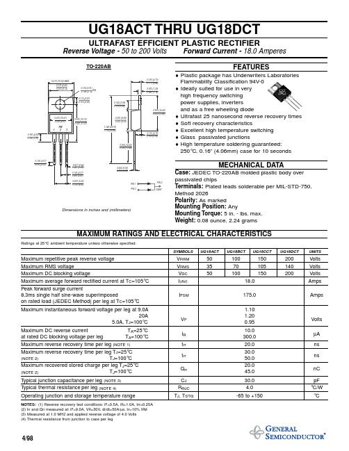
UG18ACT THRU UG18DCTULTRAFAST EFFICIENT PLASTIC RECTIFIERReverse Voltage -50 to 200 Volts Forward Current -18.0 AmperesFEATURES♦ Plastic package has Underwriters Laboratories Flammability Classification 94V-0♦ Ideally suited for use in very high frequency switching power supplies, inverters and as a free wheeling diode♦ Ultrafast 25 nanosecond reverse recovery times ♦ Soft recovery characteristics♦ Excellent high temperature switching ♦ Glass passivated junctions♦ High temperature soldering guaranteed:250°C, 0.16”(4.06mm) case for 10 secondsMECHANICAL DATACase:JEDEC TO-220AB molded plastic body over passivated chipsTerminals:Plated leads solderable per MIL-STD-750,Method 2026Polarity:As marked Mounting Position:AnyMounting Torque:5 in.- lbs.max.Weight:0.08 ounce, 2.24 gramsMAXIMUM RATINGS AND ELECTRICAL CHARACTERISTICSRatings at 25°C ambient temperature unless otherwise specified.SYMBOLS UG18ACT UG18BCT UG18CCT UG18DCT UNITSMaximum repetitive peak reverse voltage V RRM 50100150200Volts Maximum RMS voltageV RMS 3570105140Volts Maximum DC blocking voltageV DC 50100150200Volts Maximum average forward rectified current at T C =105°C I (AV)18.0Amps Peak forward surge current8.3ms single half sine-wave superimposedI FSM175.0Ampson rated load (JEDEC Method) per leg at T C =105°C Maximum instantaneous forward voltage per leg at 9.0A1.1020A1.205.0A, T J =100°C V F 0.95Volts Maximum DC reverse current T A =25°C 10.0at rated DC blocking voltage per leg T A =100°C I R 300.0µA Maximum reverse recovery time per leg (NOTE 1)t rr 20.0ns Maximum reverse recovery time per leg T J =25°C30.0(NOTE 2)T J =100°C t rr 50.0ns Maximum recovered stored charge per leg T J =25°C20.0(NOTE 2)T J =100°C Q rr 45.0 nC Typical junction capacitance per leg (NOTE 3)C J 30.0pF Typical thermal resistance per leg (NOTE 4)R ΘJC 4.0°C/W Operating junction and storage temperature rangeT J , T STG-65 to +150°CNOTES:(1) Reverse recovery test conditions:I F =0.5A, I R =1.0A, Irr=0.25A (2) t rr and Q rr measured at:I F =9.0A, V R =30V , di/dt=50A/µs, I rr=10% I RM (3) Measured at 1.0 MH Z and applied reverse voltage of 4.0 Volts (4) Thermal resistance from junction to case per leg4/98Dimensions in inches and (millimeters)RATINGS AND CHARACTERISTIC CURVES UG18ACT THRU UG18DCT。
道依茨大柴国四产品介绍

主要差异:由于国四喷射压力,性能要求方面的改变,要求对发动机本体 进行加强。
Ø采用1011010-26E机油泵,较55D安装尺寸变宽,供油能力加强。 Ø缸体采用1002010-26E,较55D相比,机油泵安装孔变动。 Ø缸盖采用1003020-C650。 Ø增加封装DOC+POC的消音器(颗粒过滤器集成消音器总成) Ø后处理控制部分只增加一个排气压差传感器 Ø电控系统,燃油系统,后处理部分的变化,见下表。
Oxi-Cat 2NO+O2→2NO2
Exhaust Urea injection
Air
EuroⅢ
2 POC
1.SCR
EuroⅤ
1. 0 2. 0
EuroⅣ
3. 0 4. 0 5. 0 6. 0 7. 0 8. 0 9. 0 10. 0
NOx Emissions [g/kWh]
Hydro-Cat (NH2) 2 CO+H2O →2NH 3+CO 2
CA4DC2-12E4系列: 排量3L 额定转速3200r/min 120PS
N2 类 轻 型 卡 车 ( 3T )
GB17691-2005 CA4DC2-10E4系列: 排量3L 额定转速3200r/min 100PS CEGR+DOC+POC
N2类轻型卡车(1.5T~2T)
CA4DC 2VE4产品技术特点
2、EGR+DOC+POC
EGR废气再循环机内降低NOx排放原理
PM Emissions [g/kWh]
0.2 0.18 Path to meet E4 EGR + PM aftertreatment Low PM combustion +SCR
MC4000液体渗透检验RCCM中文版法国民用核电标准
MC4000液体渗透检验RCCM中文版法国民用核电标准MC4100 总则MC4110 适用范畴本章阐述了本规则中规定的液体渗透检验的一样要求。
MC4120 一样要求MC4121 检验人员资格液体渗透检验,应由具有符合MC8000规定的合格证书的人员实施。
MC4122 液体渗透检验文件应按一系列通过适当确认的文件(规程、操作卡、细则卡)规定的条件进行所有的液体渗透检验;这些文件应满足RCC—M相关章节给出的要求,并应至少包括以下内容:——被检安的类型和所使用的材料的类型;——涉及的RCC—M相关章节和其它适用的文件;——检验设备;清洗和液体渗透检验用的设备以及试剂;——检验条件:被检验区和表面状况;——检验规程:渗透方法、检验参数(零件温度,停留时刻等);——验收准则。
MC4200 检验方法AFNOR标准NF A09-120规定的检验程序是适用的,但应作如下修正:——其4.5节,由以下内容代替:“用敏化试验法(遵循NF A09-521),在标准NF A09-520附录A中规定的Ni—Cr标准裂纹试样上,进行液体渗透试剂适用范畴分类。
抗过冲刷试验也应按照NF A09-521标准进行。
”“试剂的适用范畴至少应达到以下性能水平:——其5.1节,补充如下:“必须遵守RCC—M第V卷的F6423节的‘一样规则’包含的要求(用于奥氏体钢或镍基合金检验用的试剂的卤素和(或)硫含量的限制)。
”——其5.2节仅适用于使用再循环试剂的情形。
——其5.3节,补充如下:“最终或中间时期的焊缝表面(根部焊道或填充焊道)能够保持焊后状态。
在堆焊情形下,焊道之间的沟痕能够保留。
”“在液体渗透检验前进行喷砂或喷丸处理,只适用于原铸造状态的零件。
”“经磨削或表面机加工的表面粗糙度(Ra)最大值为6.3μm,经喷丸处理的原铸造状态的零件的粗糙度(Ra)最大值为12.5μm。
应按MC7200评定粗糙度。
”——其6.1.1节,由下列内容代替:“除非另有规定,否则在整个渗透检验过程中,被检零件和使用的渗透液的温度应保持在10℃到50℃之间。
- 1、下载文档前请自行甄别文档内容的完整性,平台不提供额外的编辑、内容补充、找答案等附加服务。
- 2、"仅部分预览"的文档,不可在线预览部分如存在完整性等问题,可反馈申请退款(可完整预览的文档不适用该条件!)。
- 3、如文档侵犯您的权益,请联系客服反馈,我们会尽快为您处理(人工客服工作时间:9:00-18:30)。
.050 ±.010
DDU18-xxC4 (Commercial SMD) DDU18-xxMC4 (Military SMD)
Doc #97041
5/5/04
DATA DELAY DEVICES, INC.
3 Mt. Prospect Ave. Clifton, NJ 07013
3
元器件交易网
Doc #97041
5/5/04
DATA DELAY DEVICES, INC.
Tel: 973-773-2299 Fax: 973-773-9672
2
元器件交易网
DDU18
PACKAGE DIMENSIONS
24
19 18
POWER SUPPLY BYPASSING
The DDU18 relies on a stable power supply to produce repeatable delays within the stated tolerances. A 0.1uf capacitor from VEE to GND, located as close as possible to the VEE pin, is recommended. A wide VEE trace and a clean ground plane should be used.
GND T1 T2 T3 GND GND T4 T5 T6 1 3 4 5 6 7 8 9 10 11 12 13 19 18 24
data 3 delay devices, inc.
PACKAGES
IN
GND VEE
GND N/C T1 T2 T3 GND GND T4 T5 T6 T7 T8
1 2 3 4 5 6 7 8 9 10 11 12
元器件交易网
DDU18
8-TAP, ECL-INTERFACED FIXED DELAY LINE (SERIES DDU18)
FEATURES
• • • Eight equally spaced outputs Fits in 400 mil 24-pin DIP socket Input & outputs fully 100K-ECL interfaced & buffered
VCC IN T1 T2 T3 T4 T5 T6 T7 T8 GND
Functional diagram for dash numbers >= 16
2004 Data Delay Devices
NOTE: Any dash number between 4 and 200 not shown is also available.
FUNCTIONAL DESCRIPTION
PIN DESCRIPTIONS
The DDU18-series device is a 8-tap digitally buffered delay line. The IN Signal Input signal input (IN) is reproduced at the outputs (T1-T8), shifted in time by an T1-T8 Tap Outputs amount determined by the device dash number (See Table). For dash VEE -5 Volts numbers less than 16, the total delay of the line is measured from T1 to GND Ground T8. The nominal tap-to-tap delay increment is given by one-seventh of the total delay, and the inherent delay from IN to T1 is nominally 2.0ns. For dash numbers greater than or equal to 16, the total delay of the line is measured from IN to T8. The nominal tap-to-tap delay increment is given by one-eighth of this number.
24 23 22 21 20 19 18 17 16 15 14 13
IN N/C N/C N/C N/C GND VEE N/C N/C N/C N/C GND
DDU18-xx DDU18-xxM
DIP Military DIP
T7 T8
GND
DDU18-xxC4 DDU18-xxMC4
SMD Mil SMD
Doc #97041
5/5/04
DATA DELAY DEVICES, INC.
3 Mt. Prospect Ave. Clifton, NJ 07013
1
元器件交易网
DDU18
APPLICATION NOTES
HIGH FREQUENCY RESPONSE
The DDU18 tolerances are guaranteed for input pulse widths and periods greater than those specified in the test conditions. Although the device will function properly for pulse widths as small as 40% of the total delay and periods as small as 80% of the total delay (for a symmetric input), the delays may deviate from their values at low frequency. However, for a given input condition, the deviation will be repeatable from pulse to pulse. Contact technical support at Data Delay Devices if your application requires device testing at a specific input condition.
10 sec
TABLE 2: DC ELECTRICAL CHARACTERISTICS
(0C to 85C) PARAMETER High Level Output Voltage Low Level Output Voltage High Level Input Voltage Low Level Input Voltage High Level Input Current Low Level Input Current SYMBOL VOH VOL VIH VIL IIH IIL MIN -1.025 -1.810 -1.165 -1.810 0.5 TYP MAX -0.880 -1.620 -0.880 -1.475 340 UNITS V V V V µA µA NOTES VIH = MAX,50Ω to -2V VIL = MIN, 50Ω to -2V VIH = MAX VIL = MIN
VCC IN
T1
T2
T3
T4
T5
T6
T7
T8 GND
Functional diagram for dash numbers < 16
1/8 1/8 1/8 1/8 1/8 1/8 1/8 1/8
* Total delay is referenced to first tap output Input to first tap = 2.0ns ± 1ns
2.0ns 1/7 1/7 1/7 1/7 1/7 1/7 1/7
DASH NUMBER SPECIFICATIONS
Part Number DDU18-4 DDU18-8 DDU18-12 DDU18-16 DDU18-20 DDU18-24 DDU18-32 DDU18-40 DDU18-48 DDU18-56 DDU18-64 DDU18-72 DDU18-80 DDU18-100 DDU18-120 DDU18-160 DDU18-200 Total Delay (ns) 3.5 ± 1.0 * 7.0 ± 1.0 * 10.5 ± 1.0 * 16 ± 1.0 20 ± 1.0 24 ± 1.2 32 ± 1.6 40 ± 2.0 48 ± 2.4 56 ± 2.8 64 ± 3.2 72 ± 3.6 80 ± 4.0 100 ± 5.0 120 ± 6.0 160 ± 8.0 200 ± 10.0 Delay Per Tap (ns) 0.5 ± 0.3 1.0 ± 0.4 1.5 ± 0.4 2.0 ± 0.5 2.5 ± 1.0 3.0 ± 1.5 4.0 ± 2.0 5.0 ± 2.0 6.0 ± 2.0 7.0 ± 2.0 8.0 ± 2.0 9.0 ± 2.0 10.0 ± 2.5 12.5 ± 2.5 15.0 ± 3.0 20.0 ± 4.0 25.0 ± 5.0
SERIES SPECIFICATIONS
• • • • • • Minimum input pulse width: 40% of total delay Output rise time: 2ns typical Supply voltage: -5VDC ± 5% Power dissipation: 500mw typical (no load) Operating temperature: 0° to 85° C Temp. coefficient of total delay: 100 PPM/°C
