CDHV2512AA2005G2500GE1中文资料
东芝便携维修手册_凤系列 2505
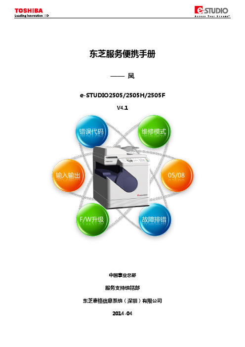
东芝服务便携手册——凤e-STUDIO2505/2505H/2505FV4.1中国事业总部服务支持统括部东芝泰格信息系统(深圳)有限公司2014-04目录一、基本清单 (2)(一)基本规格清单 (2)(二)耗材清单 (2)(三)常用电路板及零件清单 (3)(四)选购件清单 (4)(五)PM零件清单 (4)二、错误代码及故障排错参考 (5)(一)卡纸类错误代码 (5)(二)维修请求错误代码 (7)(三)E-MAIL相关错误代码 (10)(四)文件共享相关错误代码 (10)(五)其他错误 (10)三、维修模式列表 (11)四、辅助维修模式(3C) (12)五、SRAM清除模式(6C) (12)六、列表打印模式(9S) (13)七、PM支持模式(6S) (14)(一)操作流程 (14)(二)菜单列表 (14)(三)基本操作过程 (15)八、输入测试模式(03) (16)九、输出测试模式(03) (17)十、打印测试模式(04) (17)十一、05/08代码 (18)(一)常用05调整代码 (18)(二)05模式打印测试图 (21)(三)常用08设置代码 (21)(四)图像尺寸相关调整代码表 (30)(五)图像质量调整代码表(复印相关) (30)(六)图像质量调整代码表(打印相关) (31)(七)图像质量调整代码表(扫描相关)(仅2505H/F) (31)(八)ADF相关调整 (31)十二、传真错误代码及排错参考(仅2505F) (32)(一)传真卡电路相关错误代码(仅2505F) (32)(二)传真发送相关错误代码(仅2505F) (32)(三)传真接收相关错误代码(仅2505F) (34)十三、传真相关的自诊断模式(仅2505F) (36)(一)03测试模式(仅2505F) (36)(二)08设置模式(仅2505F) (36)(三)13传真功能模式(仅2505F) (36)(四)1*传真清除模式(仅2505F) (37)十四、F/W升级 (38)(一)使用USB进行F/W (38)(二)使用PC升级工具进行F/W升级 (39)十五、电路板更换 (40)(一)主板更换步骤 (40)(二)主板的EEPROM更换步骤 (40)附录 (41)(一)电器元件布局图 (41)(二)电器元件符号及功能表 (43)(三)纸路布局图 (44)(四)驱动电器布局图 (44)(五)ADF布局图 (45)(六)交流线束图 (45)(七)直流线束图(2505) (46)(八)直流线束图(2505H/F) (47)一、基本清单(一)基本规格清单注意:随机包装的墨粉容量为2K。
CKE2500使用说明书中文重要的说明
重要的说明非常感谢您购买神钢公司的履带式起重机。
CK系全液压履带式起重机是集我们多年的经验和先进技术而开发出来的。
本手册包含了CKE2500的一些重要说明。
为了保证该车的安全使用和提高作业效率,请在操作本车前仔细地阅读该手册。
■安全知识吊车操作过程中发生的许多事故,大多是由于忽视预防措施和安全规定造成的。
必须认真地采取足够的措以施避免此类事故的发生。
不正确的操作、润滑或维修是十分危险的,并有可能造成人身伤亡。
因而,在开始工作之前,必须仔细阅读并理解、掌握本书中的预防措施或说明。
必须认真仔细地进行操作、检查和维修,并且始终把安全放在首要位置。
有关安全的内容以“!”标记表示,本书涉及的安全知识仅是一些常规性的内容。
本书和吊车上出现的涉及安全的提示,以“危险”、“警告”和“注意”等字样来标明。
这些字样的含义如下:“危险”:表明紧急的危险情况,如果不能避免,将会导致死亡或重伤事故。
“警告”:表明潜在的的危险情况,如果不能避免,将会导致死亡或重伤事故。
“注意”:表明潜在的的危险情况,如果不能避免,将会导致轻伤或中等程度的伤害。
同时也用来提醒注意可能发生的机械或零部件的损坏。
“说明”:补充的解释说明。
要预测到操作过程中的每一种危险情况是极其困难的,然而,按照神钢公司的建议进行该车的操作,是能够保证安全的。
为了保证不会发生机械损坏事故或人身伤亡事故,在操作过程中要加倍小心。
要不断地阅读该手册,直至完全理解掌握该书的内容为止。
■起重机的序列编号需要订购配件和进行维修保养服务时,请注明起重机的序列号和起重机的运转小时数,序列号在起重机铭牌上,运转小时数在操作室的仪表盘上。
■填写该车的序列号■质量保证该车的质量保证范围有明确的规定,在质量保证期内,任何应由神钢公司认可的缺陷和损坏,神钢公司将进行无偿的修复。
如果没有按照本说明书的规定使用该车,任何的损坏都不在质量保证的范围内。
■维修用配件为保证该车性能,确保在维修保养时使用纯正的神钢公司配件。
MM5ZxxxST1G Serie Zener Voltage Regulators 500 mW
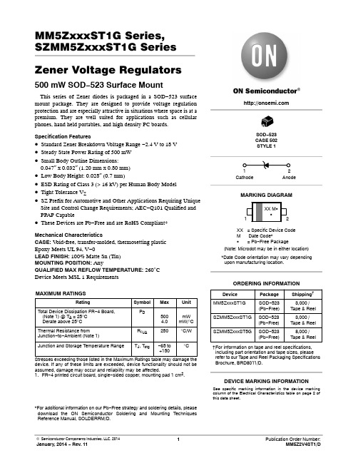
MM5ZxxxST1G Series, SZMM5ZxxxST1G Series Zener Voltage Regulators 500 mW SOD−523 Surface MountThis series of Zener diodes is packaged in a SOD−523 surface mount package. They are designed to provide voltage regulation protection and are especially attractive in situations where space is at a premium. They are well suited for applications such as cellular phones, hand held portables, and high density PC boards. Specification Features•Standard Zener Breakdown V oltage Range −2.4 V to 18 V •Steady State Power Rating of 500 mW•Small Body Outline Dimensions:0.047″ x 0.032″ (1.20 mm x 0.80 mm)•Low Body Height: 0.028″ (0.7 mm)•ESD Rating of Class 3 (> 16 kV) per Human Body Model •Tight Tolerance V Z•SZ Prefix for Automotive and Other Applications Requiring Unique Site and Control Change Requirements; AEC−Q101 Qualified and PPAP Capable•These Devices are Pb−Free and are RoHS Compliant*Mechanical CharacteristicsCASE:V oid-free, transfer-molded, thermosetting plasticEpoxy Meets UL 94, V−0LEAD FINISH: 100% Matte Sn (Tin)MOUNTING POSITION:AnyQUALIFIED MAX REFLOW TEMPERATURE: 260°CDevice Meets MSL 1 RequirementsMAXIMUM RATINGSRating Symbol Max UnitTotal Device Dissipation FR−4 Board, (Note 1) @ T A = 25°CDerate above 25°C P D5004.0mWmW/°CThermal Resistance from Junction−to−Ambient (Note 1)R q JA250°C/WJunction and Storage Temperature Range T J, T stg−65 to+150°CStresses exceeding those listed in the Maximum Ratings table may damage the device. If any of these limits are exceeded, device functionality should not be assumed, damage may occur and reliability may be affected.1.FR−4 printed circuit board, single−sided copper, mounting pad 1 cm2.*For additional information on our Pb−Free strategy and soldering details, please download the ON Semiconductor Soldering and Mounting Techniques Reference Manual, SOLDERRM/D.Device Package Shipping†ORDERING INFORMATIONCathode AnodeSee specific marking information in the device marking column of the Electrical Characteristics table on page 2 of this data sheet.DEVICE MARKING INFORMATIONSOD−523CASE 502STYLE 1MARKING DIAGRAMXX= Specific Device CodeM Date Code*G= Pb−Free Package(Note: Microdot may be in either location)*Date Code orientation may vary dependingupon manufacturing location.MM5ZxxxST1G SOD−523(Pb−Free)3,000 /Tape & Reel†For information on tape and reel specifications, including part orientation and tape sizes, please refer to our T ape and Reel Packaging Specifications Brochure, BRD8011/D.SOD−523(Pb−Free)SZMM5ZxxxST1G3,000 /Tape & ReelSOD−523(Pb−Free)SZMM5ZxxxST5G8,000 /Tape & ReelELECTRICAL CHARACTERISTICS (T A = 25°C unless otherwise noted,V F = 0.9 V Max. @ I F = 10 mA for all types) Symbol Parameter V Z Reverse Zener Voltage @ I ZTI ZT Reverse CurrentZZT Maximum Zener Impedance @ I ZTI ZK Reverse CurrentZ ZK Maximum Zener Impedance @ I ZKI R Reverse Leakage Current @ V RV R Reverse VoltageI F Forward CurrentV F Forward Voltage @ I FQ V Z Maximum Temperature Coefficient of V Z C Max. Capacitance @V R = 0 and f = 1 MHzV Figure 1. Zener Voltage RegulatorELECTRICAL CHARACTERISTICS (V F = 0.9 Max @ I F = 10 mA for all types)Device*DeviceMarkingTestCurrentIzt mAZener VoltageVZZ ZK I Z= 1.0mA WMaxZ ZTI Z = IZT@ 10%Mod WMaxMaxIR @ VRd VZ/dt (mV/k)@ I ZT1 = 5 mA C pF Max @V R = 0f = 1 MHzMin Max m A V Min MaxMM5Z2V4ST1G T2 5.0 2.43 2.631000100120 1.0−3.50450MM5Z2V7ST1G T3 5.0 2.67 2.911000100100 1.0−3.50450MM5Z3V3ST1G T5 5.0 3.32 3.53100095 5.0 1.0−3.50450MM5Z3V6ST1G T6 5.0 3.60 3.85100090 5.0 1.0−3.50450MM5Z3V9ST1G T7 5.0 3.89 4.16100090 3.0 1.0−3.5−2.5450MM5Z4V3ST1G T8 5.0 4.17 4.43100090 3.0 1.0−3.50450MM5Z4V7ST1G/T5G T9 5.0 4.55 4.7580080 3.0 2.0−3.50.2260MM5Z5V1ST1G TA 5.0 4.98 5.250060 2.0 2.0−2.7 1.2225MM5Z5V6ST1G TC 5.0 5.49 5.7320040 1.0 2.0−2.0 2.5200MM5Z6V2ST1G TE 5.0 6.06 6.3310010 3.0 4.00.4 3.7185MM5Z6V8ST1G TF 5.0 6.65 6.9316015 2.0 4.0 1.2 4.5155MM5Z7V5ST1G TG 5.07.287.616015 1.0 5.0 2.5 5.3140MM5Z8V2ST1G TH 5.08.028.36160150.7 5.0 3.2 6.2135MM5Z9V1ST1G TK 5.08.859.23160150.5 6.0 3.87.0130MM5Z12VST1G TN 5.011.7412.2480250.18.0 6.010130MM5Z16VST1G TU 5.015.8516.5180400.0511.210.414105MM5Z18VST1G TW 5.017.5618.3580450.0512.612.416100 Product parametric performance is indicated in the Electrical Characteristics for the listed test conditions, unless otherwise noted. Product performance may not be indicated by the Electrical Characteristics if operated under different conditions.*Include SZ-prefix devices where applicable.TYPICAL CHARACTERISTICSTEMPERATURE (°C)25010040200P O W E R D I S S I P A T I O N (%)50751001251508060Figure 2. Steady State Power DeratingPACKAGE DIMENSIONSSOD −523CASE 502ISSUE ENOTES:1.DIMENSIONING AND TOLERANCING PER ASME Y14.5M, 1994.2.CONTROLLING DIMENSION: MILLIMETERS.3.MAXIMUM LEAD THICKNESS INCLUDES LEAD FINISH.MINIMUM LEAD THICKNESS IS THE MINIMUM THICKNESS OF BASE MATERIAL.4.DIMENSIONS D AND E DO NOT INCLUDE MOLD FLASH, PRO-TRUSIONS, OR GATE BURRS.DIM MIN NOM MAX MILLIMETERS D 1.10 1.20 1.30E 0.700.800.90A 0.500.600.70b 0.250.300.35c 0.070.140.20L 0.30 REF H 1.50 1.60 1.70*For additional information on our Pb −Free strategy and soldering details, please download the ON Semiconductor Soldering and Mounting Techniques Reference Manual, SOLDERRM/D.SOLDERING FOOTPRINT*E RECOMMENDEDSIDE VIEW2XBOTTOM VIEWL2L2X2XL20.150.200.25STYLE 1:PIN 1.CATHODE (POLARITY BAND)2.ANODEON Semiconductor and are registered trademarks of Semiconductor Components Industries, LLC (SCILLC). SCILLC reserves the right to make changes without further notice to any products herein. SCILLC makes no warranty, representation or guarantee regarding the suitability of its products for any particular purpose, nor does SCILLC assume any liability arising out of the application or use of any product or circuit, and specifically disclaims any and all liability, including without limitation special, consequential or incidental damages.“Typical” parameters which may be provided in SCILLC data sheets and/or specifications can and do vary in different applications and actual performance may vary over time. All operating parameters, including “Typicals” must be validated for each customer application by customer’s technical experts. SCILLC does not convey any license under its patent rights nor the rights of others. SCILLC products are not designed, intended, or authorized for use as components in systems intended for surgical implant into the body, or other applications intended to support or sustain life, or for any other application in which the failure of the SCILLC product could create a situation where personal injury or death may occur. Should Buyer purchase or use SCILLC products for any such unintended or unauthorized application, Buyer shall indemnify and hold SCILLC and its officers, employees, subsidiaries, affiliates,and distributors harmless against all claims, costs, damages, and expenses, and reasonable attorney fees arising out of, directly or indirectly, any claim of personal injury or death associated with such unintended or unauthorized use, even if such claim alleges that SCILLC was negligent regarding the design or manufacture of the part. SCILLC is an Equal Opportunity/Affirmative Action Employer. This literature is subject to all applicable copyright laws and is not for resale in any manner.PUBLICATION ORDERING INFORMATION。
2512中文资料

For more information, contact Pulse Consumer Division Applications Engineering via e-mail at: consumer@.
46
G003.U (2/07)
元器件交易网
14"- 90° color TV Set-top Box 14"÷21" - 90° 17"÷21" - 90° 110° Color TV 25"÷29" 110° Color TV 28"÷34" 110° Color TV 14"-15" CTV 90° 25"-29" CTV 110° LCD TV 26" LCD TV 26"-32"
Series (Part Number)
2182 2414 2444 2464 2074 2074.5 2084 2094 2344 2354
2502 2502.5 2512 2522 2532 2542 2552 2562 2102 2722 2732
2742
2432 2182.5 2252 2262 2262.5 2362 2361 2362.3 2362.5 2362.7 2452 2452.7 2472
Applications
This transformer is mainly intended to be used as a Resonant Switch-Mode Transformer for low-end 22” LCD TV sets with mains insulation. The most suitable circuit topology for this transformer is a half-bridge, quasi-resonant converter using Phillips ZVS controller TEA1610. The common range of operation for this switch-mode transformer is from 50-200 kHz.
NPort W2150A W2250A 系列无线串行设备服务器说明文档说明书
NPort W2150A/W2250A系列1和2埠RS-232/422/485IEEE802.11a/b/g無線串列設備伺服器特色與優點•可將任何串列裝置連接至IEEE802.11a/b/g網路•透過內建乙太網路或WLAN執行Web-based設定•強化的區域網路、串列和電力突波保護•利用HTTPS和SSH強化遠端設定•透過WEP、WPA和WPA2保護存取資料的安全性•快速漫遊,可在存取點之間快速自動切換•具備離線埠緩衝和串列資料記錄功能•雙電源輸入(1螺旋式電源接頭、1端子台)認證簡介NPort®W2150A和W2250A是將串列和乙太網路裝置(例如PLC、儀表和感測器)連接到無線LAN的理想選擇。
您的通訊軟體將能夠透過無線LAN隨處存取串列裝置。
此外,無線裝置伺服器需要較少纜線,相當適合不便佈線的應用。
在基礎架構模式或Ad-Hoc模式中,NPort®W2150A和NPort®W2250A可以連接辦公室和工廠的Wi-Fi網路,以便使用者在多個AP(存取點)之間移動或漫遊,並且對於經常在不同的地點之間移動的裝置提供絕佳的解決方案。
規格Ethernet Interface10/100BaseT(X)Ports(RJ45connector)1Magnetic Isolation Protection 1.5kV(built-in)Standards IEEE802.3for10BaseTIEEE802.3u for100BaseT(X)Ethernet Software FeaturesConfiguration Options Web Console(HTTP/HTTPS),Windows UtilityManagement DHCP Option82,HTTP,IPv4,SMTP,SNMPv1/v2c/v3,Syslog,Telnet,Web Console Windows Real COM Drivers Windows95/98/ME/NT/2000,Windows XP/2003/Vista/2008/7/8/8.1/10(x86/x64),Windows2008R2/2012/2012R2/2016/2019(x64),Windows Embedded CE5.0/6.0,Windows XP EmbeddedLinux Real TTY Drivers Kernel versions:2.4.x,2.6.x,3.x,4.x,and5.xFixed TTY Drivers SCO UNIX,SCO OpenServer,UnixWare7,QNX4.25,QNX6,Solaris10,FreeBSD,AIX5.x,HP-UX11i,Mac OS XAndroid API Android3.1.x and laterMIB Device Settings MIB,RFC1213,RFC1317Security HTTPS/SSL,User Authentication Management:local database,RADIUS,SecureProtocols:HTTPS(TLSv1.2),SSH,SNMPv3,Cryptography:HMAC,SHA-1,SHA-256,SHA-384,RSA-1024,AES-128,AES-256Time Management NTP Client,SNTP ClientWLAN InterfaceWLAN Standards802.11a/b/g/nReceiver Sensitivity for802.11a(measured at5.680 GHz)Typ.-91@6Mbps Typ.-74@54MbpsReceiver Sensitivity for802.11b(measured at2.437 GHz)Typ.-92dBm@1Mbps Typ.-84dBm@11MbpsReceiver Sensitivity for802.11g(measured at2.437 GHz)Typ.-91dBm@6Mbps Typ.-73dBm@54MbpsReceiver Sensitivity for802.11n(2.4GHz;measured at2.437GHz)Typ.-89dBm@6.5Mbps(20MHz) Typ.-71dBm@72.2Mbps(20MHz)Receiver Sensitivity for802.11n(5GHz;measured at 5.680GHz)Typ.-89dBm@6.5Mbps(20MHz) Typ.-71dBm@72.2Mbps(20MHz) Typ.-85dBm@13.5Mbps(40MHz) Typ.-67dBm@150Mbps(40MHz)Modulation Type DSSSOFDMTransmission Distance Up to100meters(in open areas) Transmission Rate802.11a/g:54Mbps802.11b:11Mbps802.11n:6.5to150Mbps Transmitter Power for802.11b16±1.5dBm@1Mbps16±1.5dBm@11Mbps Transmitter Power for802.11g16±1.5dBm@6Mbps14±1.5dBm@54Mbps Transmitter Power for802.11a15±1.5dBm@6Mbps14±1.5dBm@54Mbps Transmitter Power for802.11n(2.4GHz)16dBm@1.5Mbps(6.5MHz)12dBm@1.5Mbps(72.2MHz) Transmitter Power for802.11n(5GHz)15dBm@1.5Mbps(6.5MHz)12dBm@1.5Mbps(150MHz) Frequency Band for CN(20MHz operating channels) 2.412to2.472GHz(13channels)5.180to5.240GHz(4channels)5.260to5.320GHz(4channels)15.745to5.825GHz(5channels) Frequency Band for EU(20MHz operating channels) 2.412to2.472GHz(13channels)5.180to5.240GHz(4channels)5.260to5.320GHz(4channels)15.500to5.700GHz(11channels)1 Frequency Band for JP(20MHz operating channels) 2.412to2.484GHz(14channels)5.180to5.240GHz(4channels)5.260to5.320GHz(4channels)15.500to5.700GHz(11channels)1 Frequency Band for US(20MHz operating channels) 2.412to2.462GHz(11channels)5.180to5.240GHz(4channels)5.260to5.320GHz(4channels)25.500to5.700GHz(11channels)25.745to5.825GHz(5channels)Wireless Security WEP encryption(64-bit and128-bit)WPA/WPA2-Enterprise(IEEE802.1X/RADIUS,TKIP,AES)WPA/WPA2-PersonalWLAN Modes Ad-hoc Mode,Infrastructure modeSerial InterfaceConnector DB9maleNo.of Ports NPort W2150A/W2150A-T:1NPort W2250A/W2250A-T:2Serial Standards RS-232,RS-422,RS-485Operation Modes Real COM mode,TCP Server mode,TCP Client mode,UDP mode,RFC2217mode,PairConnection mode,Ethernet Modem mode,DisabledBaudrate50bps to921.6kbpsData Bits5,6,7,8Stop Bits1,1.5,2Parity None,Even,Odd,Space,MarkFlow Control None,RTS/CTS,XON/XOFFRS-485Data Direction Control ADDC®(automatic data direction control)Pull High/Low Resistor for RS-4851kilo-ohm,150kilo-ohmsTerminator for RS-485120ohmsSurge1kVPhysical CharacteristicsHousing MetalInstallation Desktop,DIN-rail mounting(with optional kit),Wall mountingDimensions(with ears,without antenna)77x111x26mm(3.03x4.37x1.02in)Dimensions(without ears or antenna)100x111x26mm(3.94x4.37x1.02in)Weight NPort W2150A/W2150A-T:547g(1.21lb)NPort W2250A/W2250A-T:557g(1.23lb)Antenna Length109.79mm(4.32in)Environmental LimitsOperating Temperature Standard Models:0to55°C(32to131°F)Wide Temp.Models:-40to75°C(-40to167°F)Storage Temperature(package included)-40to75°C(-40to167°F)Ambient Relative Humidity5to95%(non-condensing)Power ParametersInput Current NPort W2150A/W2150A-T:179mA@12VDCNPort W2250A/W2250A-T:200mA@12VDCInput Voltage12to48VDCStandards and CertificationsEMC EN55032/24EMI CISPR32,FCC Part15B Class AEMS IEC61000-4-2ESD:Contact:4kV;Air:8kVIEC61000-4-3RS:80MHz to1GHz:3V/mIEC61000-4-4EFT:Power:2kV;Signal:2kVIEC61000-4-5Surge:Power:2kV;Signal:1kVIEC61000-4-6CS:150kHz to80MHz:3V/m;Signal:3V/mIEC61000-4-8PFMFIEC61000-4-11Radio Frequency CE(ETSI EN301893,ETSI EN300328,ETSI EN301489-17,ETSI EN301489-1),ARIBRCR STD-33,ARIB STD-66ReliabilityAlert Tools RTC(real-time clock)Automatic Reboot Trigger Built-in WDTMTBFTime NPort W2150A/W2150A-T:383,187hrsNPort W2250A/W2250A-T:363,327hrsStandards Telcordia(Bellcore)Standard TR/SRWarrantyWarranty Period5yearsDetails See /tw/warrantyPackage ContentsDevice1x NPort W2150A/W2250A Series device serverPower Supply1x power adapter,suitable for your region(standard temp.models only)Antenna1x2.4/5GHz antennaDocumentation1x quick installation guide1x warranty card尺寸訂購資訊Model Name No.of serial portsWLAN Channels Input Current Operating Temp.Power Adapter inBox Notes NPort W2150A-CN 1China bands 179mA @12VDC 0to 55°C Yes (CN plug)—NPort W2150A-EU 1Europe bands 179mA @12VDC 0to 55°C Yes (EU/UK/AUplug)—NPort W2150A-EU/KC 1Europe bands 179mA @12VDC 0to 55°C Yes (EU plug)KC certificateNPort W2150A-JP 1Japan bands 179mA @12VDC 0to 55°C Yes (JP plug)—NPort W2150A-US 1US bands 179mA @12VDC 0to 55°C Yes (US plug)—NPort W2150A-T-CN 1China bands 179mA @12VDC -40to 75°C No —NPort W2150A-T-EU 1Europe bands 179mA @12VDC -40to 75°C No —NPort W2150A-T-JP 1Japan bands 179mA @12VDC -40to 75°C No —NPort W2150A-T-US 1US bands 179mA @12VDC -40to 75°C No —NPort W2250A-CN 2China bands 200mA @12VDC 0to 55°C Yes (CN plug)—NPort W2250A-EU 2Europe bands 200mA @12VDC 0to 55°C Yes (EU/UK/AUplug)—NPort W2250A-EU/KC 2Europe bands 200mA @12VDC 0to 55°C Yes (EU plug)KC certificateNPort W2250A-JP 2Japan bands 200mA @12VDC 0to 55°C Yes (JP plug)—NPort W2250A-US 2US bands 200mA @12VDC 0to 55°C Yes (US plug)—NPort W2250A-T-CN 2China bands 200mA @12VDC -40to 75°C No —NPort W2250A-T-EU 2Europe bands 200mA @12VDC -40to 75°C No —NPort W2250A-T-JP 2Japan bands 200mA @12VDC -40to 75°C No —NPort W2250A-T-US2US bands200mA @12VDC-40to 75°CNo—配件(選購)AntennasANT-WDB-ARM-02 2.4/5GHz,omni-directional rubber duck antenna,2dBi,RP-SMA(male)CablesCBL-F9M9-150DB9female to DB9male serial cable,1.5mCBL-F9M9-20DB9female to DB9male serial cable,20cmConnectorsADP-RJ458P-DB9F DB9female to RJ45connectorMini DB9F-to-TB DB9female to terminal block connectorDIN-Rail Mounting KitsDK35A DIN-rail mounting kit,35mmPower AdaptersPWR-12050-WPAU-S1Locking barrel plug,12VDC,0.5A,100-240VAC,Australia(AU)plug,0to40°C operating temperature PWR-12050-WPCN-S1Locking barrel plug,12VDC,0.5A,100to240VAC,China(CN)plug,0to40°C operating temperature PWR-12050-WPEU-S1Locking barrel plug,12VDC,0.5A,100-240VAC,Continental Europe(EU)plug,0to40°C operatingtemperaturePWR-12050-WPUK-S1Locking barrel plug,12VDC,0.5A,100-240VAC,United Kingdom(UK)plug,0to40°C operatingtemperaturePWR-12050-WPUSJP-S1Locking barrel plug,12VDC,0.5A,100-240VAC,United States/Japan(US/JP)plug,0to40°C operatingtemperaturePWR-12150-AU-SA-T Locking barrel plug,12VDC,1.5A,100-240VAC,Australia(AU)plug,-40to75°C operating temperatureApplicable Models:NPort W2150A-TNPort W2250A-TPWR-12150-CN-SA-T Wide-temperature(-40to75°C)locking barrel plug,12VDC,1.5A,100to240VAC,China(CN)plugApplicable Models:NPort W2150A-TNPort W2250A-TPWR-12150-EU-SA-T Locking barrel plug,12VDC,1.5A,100-240VAC,Continental Europe(EU)plug,-40to75°C operatingtemperatureApplicable Models:NPort W2150A-TNPort W2250A-TPWR-12150-UK-SA-T Locking barrel plug,12VDC,1.5A,100-240VAC,United Kingdom(UK)plug,-40to75°C operatingtemperatureApplicable Models:NPort W2150A-TNPort W2250A-TPWR-12150-USJP-SA-T Locking barrel plug,12VDC1.5A,100-240VAC,United States/Japan(US/JP)plug,-40to75°Coperating temperatureApplicable Models:NPort W2150A-TNPort W2250A-TPower CordsCBL-PJ21NOPEN-BK-30Locking barrel plug to bare-wire cable©Moxa Inc.版權所有.2021年1月25日更新。
CDHV2512BD2005H2500GE1中文资料
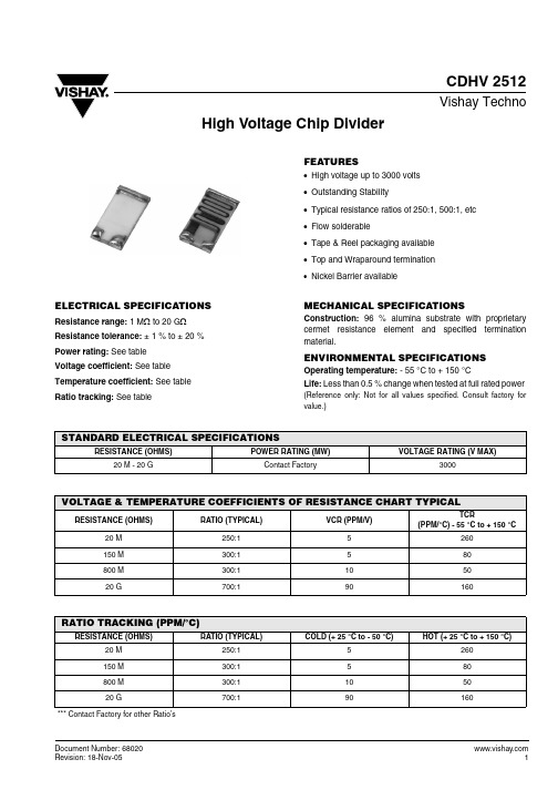
CDHV 2512Vishay TechnoDocument Number: High Voltage Chip DividerFEATURES•High voltage up to 3000 volts •Outstanding Stability•Typical resistance ratios of 250:1, 500:1, etc •Flow solderable•Tape & Reel packaging available •Top and Wraparound termination•Nickel Barrier availableELECTRICAL SPECIFICATIONSResistance range: 1 M Ω to 20 G ΩResistance tolerance: ± 1 % to ± 20 %Power rating: See table Voltage coefficient: See table Temperature coefficient: See table Ratio tracking: See tableMECHANICAL SPECIFICATIONSConstruction: 96 % alumina substrate with proprietary cermet resistance element and specified termination material.ENVIRONMENTAL SPECIFICATIONSOperating temperature: - 55 °C to + 150 °CLife: Less than 0.5 % change when tested at full rated power(Reference only: Not for all values specified. Consult factory for value.)STANDARD ELECTRICAL SPECIFICATIONSRESISTANCE (OHMS)POWER RATING (MW)VOLTAGE RATING (V MAX)20 M - 20 GContact Factory3000VOLTAGE & TEMPERATURE COEFFICIENTS OF RESISTANCE CHART TYPICALRESISTANCE (OHMS)RATIO (TYPICAL)VCR (PPM/V)TCR(PPM/°C) - 55 °C to + 150 °C20 M 250:15260150 M 300:1580800 M 300:1105020 G700:190160RATIO TRACKING (PPM/°C)RESISTANCE (OHMS)RATIO (TYPICAL)COLD (+ 25 °C to - 50 °C)HOT (+ 25 °C to + 150 °C)20 M 250:15260150 M 300:1580800 M 300:1105020 G700:190160*** Contact Factory for other Ratio’sORDERING INFORMATIONCDHV2512A A2005J2500G e1MODEL TERMINA TIONSTYLE TERMINA TIONMA TERIALVALUER1ABSOLUTETOLERANCERA TIOR1/R2RA TIOTOLERANCETERMINA TIONMA TERIALA = WraparoundB = T op only A = Palladium SilverB = Platinum GoldC = GoldD = Platinum SilverE = Palladium GoldF = Nickel BarrierResistance Value of R1:The first 3 digits aresignificant. The last digitspecifies the number ofzeros to follow.F = 1 %G = 2 %H = 3 %J = 5 %K = 10 %M = 20 %The first 3 digitsare significant.The last digitspecifies thenumber of zeros tofollow.F = 1 %G = 2 %H = 3 %J = 5 %S2 = Sn62e1 = Sn95/5 Document Number: 68020Legal Disclaimer NoticeVishayNoticeSpecifications of the products displayed herein are subject to change without notice. Vishay Intertechnology, Inc., or anyone on its behalf, assumes no responsibility or liability for any errors or inaccuracies.Information contained herein is intended to provide a product description only. No license, express or implied, by estoppel or otherwise, to any intellectual property rights is granted by this document. Except as provided in Vishay's terms and conditions of sale for such products, Vishay assumes no liability whatsoever, and disclaims any express or implied warranty, relating to sale and/or use of Vishay products including liability or warranties relating to fitness for a particular purpose, merchantability, or infringement of any patent, copyright, or other intellectual property right. The products shown herein are not designed for use in medical, life-saving, or life-sustaining applications. Customers using or selling these products for use in such applications do so at their own risk and agree to fully indemnify Vishay for any damages resulting from such improper use or sale.。
场效应管参数大全2【范本模板】
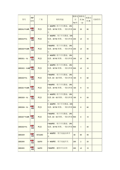
型号PDF资料厂商特性用途极限电压Vm(V)极限电流Im(A)耗散功率(W)代换型号2SK2518-01MR FUJI N—MOSFET,用于开关整流、UPS电源、DC-DC转换、一般功率放大200 20 502SK2519-01 FUJI N—MOSFET,用于开关整流、UPS电源、DC-DC转换、一般功率放大200 10 402SK2520-01MR FUJI N-MOSFET,用于开关整流、UPS电源、DC-DC转换、一般功率放大200 10 302SK2521—01 FUJI N—MOSFET,用于开关整流、UPS电源、DC-DC转换、一般功率放大200 18 502SK2522—01MR FUJI N—MOSFET,用于开关整流、UPS电源、DC-DC转换、一般功率放大300 18 402SK2523-01 FUJI N-MOSFET,用于开关整流、UPS电源、DC—DC转换、一般功率放大450 9 602SK2524-01MR FUJI N-MOSFET,用于开关整流、UPS电源、DC-DC转换、一般功率放大450 9 402SK2525—01 FUJI N—MOSFET,用于开关整流、UPS电源、DC—DC转换、一般功率放大450 9 802SK2526—01 FUJI N—MOSFET,用于开关整流、UPS电源、DC-DC转换、一般功率放大900 5 602SK2527-01MR FUJI N-MOSFET,用于开关整流、UPS电源、DC—DC转换、一般功率放大900 5 402SK2528-01 FUJI N-MOSFET,用于开关整流、UPS电源、DC-DC转换、一般功率放大900 4 802SK2529 HITACHI N—MOSFET,用于高速功率开关60 50 352SK2530 SANYO N—MOSFET,用于高速开关250 2 20 2SK2532 SANYO N-MOSFET,通用开关应用250 10 402SK2533 SANYO N—MOSFET,用于高速开关250 2 20 2SK2534 SANYO N—MOSFET,通用开关应用250 16 502SK2538 PANASONIC N-MOSFET,用于高速开关、高频功率放大250 2 302SK2539 PANASONIC N-MOSFET,用于高频功率放大、模拟开关15 0。
1002 212 025说明书

Safety Information . . . . . . . . . . . . . . . . . . . . . . . . . . . . . . . . . . 2 Warranty . . . . . . . . . . . . . . . . . . . . . . . . . . . . . . . . . . . . . . . . . . 3 Pre-Installation . . . . . . . . . . . . . . . . . . . . . . . . . . . . . . . . . . . . . 3 Installation . . . . . . . . . . . . . . . . . . . . . . . . . . . . . . . . . . . . . . . . 6Before you begin, carefully read and understand the instructions in this manual. Please follow the instructions in the order presented inthis manual and observe all warnings and cautions.This mount has been tested to support a television with a minimum of 20 in. (51 cm) and a maximum 56 in. (142 cm)diagonal screen and a weight up to 80 lbs. (36 kgs).The manufacturer warrants that it will replace or repair this item, free of charge, at the manufacturer’s sole discretion, should it prove defective in materials or workmanship.This warranty does not apply to:□Normal wear and tear□Friction damage□Coating defects□Defects caused by loosened screws, nuts, or bolts□Improperly mounting the bracket to the wall□Improperly installing the bracket to the display□Failure to properly follow installation instructions□Modifi cation or repairs not made or authorized by the manufacturer□Loading beyond permitted load□Intentional misuseContact the Customer Service Team at 1-877-527-0313 or visit .PLANNING INSTALLATIONCompare all parts in the package with the Hardware Included and Package Contents lists in this manual. If any part is missing or damaged, do not install this wall mount system and call customer service at 1-877-527-0313 or visit .This wall mount bracket is compatible with VESA 100/200/300/400 mm mounting holes.PLANNING WALL PLACEMENTWhen selecting a wall to mount your display, keep the following in mind:□Select a place with easy access to power outlets, cable input sources, and connections for speakers and accessories.□Avoid direct sunlight, heat, and vibrations and do not place in direct fl ow of traffi c.□Select a weight-bearing wall. The wall must be able to safely support four times the combined load of the equipment and all attached hardware and components.PLANNING MOUNTING HEIGHTThe optimal viewing height is to center the display at eye level when seated. Many people consider this to be too low for a wall mount, and commonly use the following rule for placement:□Position the bottom of the display no higher than eye level when seated, and the top of the display no higher than eye level when standing. Anything within these limits should normally provide a comfortable viewing experience.ENSURING WALL STABILITYCarefully inspect the wall area you have selected. Examine the wall surface before you begin drilling.□For concrete walls, check for damaged or loose concrete and do not drill in those areas. □For brick wall, never drill into the mortar between blocks.□For wood studs, locate the wall studs and drill in the center of the stud.TOOLS REQUIRED (NOT INCLUDED IN THE PACKAGING)Power drill5-32 in. (4 mm) wood drill bit or 3/8 in. (10 mm) masonry drillbitsPhillipsscrewdriverStud finderMeasuringtapePencil HammerHARDWARE INCLUDEDAA BB CC DD EEJJFF GG HH IIPACKAGE CONTENTS7 Attaching the mounting arm to the□Align the mounting arm holes with the pre-drilled holes in the wall.□Use the level (C) to ensure that the mounting arm (A) is level on the wall.□Attach the mounting arm (A) to the wall using lag bolts(BB). Tighten the bolts (BB) securely using a Phillipsscrewdriver and a socket tool (not included).8Attaching the mounting plate to theTV (VESA 100 and 200)This procedure describes how to attach the mounting plate to VESA 100 and 200 TVs. For VESA 300 and 400, proceed to step 9. □If necessary, align spacers (EE) or (FF) over the mounting holes on the back of your TV. □Position the wall plate (A) over the TV and attach using the appropriately sized bolts (CC or DD) and washers(GG or HH).EE/FFAGG/HHDD AGG/HH100x100 / 200x200100x100 / 200x200CC9Attaching the mounting plate to the TV (VESA 300 and 400)□Attach the left and right arm extenders (B1 and B2) to the wall plate (A) using M6 x 8 bolts (II). □Align spacers (EE or FF) over the mounting holes on the back of your TV. □Position the wall plate (A) with extenders (B) over spacers (EE or FF) and attach them to the TV using the appropriate sized bolts (CC or DD) and washers (GG or HH).CC II JJB1B2B1B2GG/HHDD EE/FFGG/HH12 Adjusting the angle of the TV□Adjust the angle of the TV by loosening the handle (1) on the wall plate assembly (A). Refer to the fi gure for the various angle adjustments. Securely tighten the handle (1) when you are fi nished.Questions, problems, missing parts? Before returning to the store, call Commercial Electric Customer Service8 a.m. - 7 p.m., EST, Monday-Friday, 9 a.m. - 6 p.m., EST, Saturday1-877-527-0313Retain this manual for future use.。
TH2512 使用说明书

使用说明书O P E R A T I O N M A N U A LM O D E LA A U UT T O O D D C C L L O O W W O O H H M M M M E E T T E E R R常常州州市市同同惠惠电电子子有有限限公公司司 C h a n g z h o u T o n g h u i E l e c t r o n i c C o . , L t d . 地地址址::江江苏苏省省常常州州市市新新北北区区天天山山路路33号号电电话话::((00551199))55113322222222,,55111133334422 传传真真::((00551199))55110099997722 邮邮箱箱::S S a a l l e e s s @@t t o o n n g g h h u u i i ..c c o o m m ..c c n n 网网址址::h h t t t t p p :://// w w w w w w ..t t o o n n g g h h u u i i ..c c o o m m ..c c n n目录1.测试中应注意的问题 (3)2.简介 (4)3.技术性能参数(SPECFICATIONS) (5)4.面板按键功能说明 (6)5.面板文字说明 (7)6.一般使用说明: (7)7.分选使用说明 (8)8.接口信号说明(Handler) (10)9.面板显示信息指示说明 (11)10.系统方块图 (11)11.校验 (12)12.远程控制功能 (16)13.成套 (19)14.保修 (19)TH2512/A使用说明书1.测试中应注意的问题1.开机预热:仪器开机,测试前必须预热10分钟以上,以等待仪器内部线路电参数稳定后再进行测试。
2.零点及清零:当使用20mΩ和200mΩ两量程时,应首先清零再进行测试,而在其它量程一般不必清零。
测试时,使用者可先选定量程,再把测试夹互夹,使S+端与S-端直接接触,D+端与D-端直接接触,并保持良好接触,若仪器显示不为零时,请按前面板清零键,则清零ON指示灯亮,仪器清零。
ZX2512系列说明书
4.1.2 测试速度 ...................................................................................................................... 13 4.1.3 偏差功能 ..................................................................................................................... 14 4.1.4 比较器功能 ON/OFF(比较) .................................................................................... 14 4.1.5 比较功能极限模式 ...................................................................................................... 15 4.1.6 容差模式标称值设置................................................................................................... 15 4.1.7 上限和下限(档 1) .................................................................................................... 16 4.1.8 文件管理 ...................................................................................................................... 16 4.1.9 其它工具 ...................................................................................................................... 16 4.2 <档计数显示>页面 .............................................................................................................. 16 4.2.1 标称 ............................................................................................................................. 17 4.2.2 档序号 ......................................................................................................................... 17 4.2.3 极限列表上下限 .......................................................................................................... 17 4.2.4 计数 ............................................................................................................................. 17 4.2.5 超差(OUT) .............................................................................................................. 17 4.2.6 文件管理(文件) ....................................................................................................... 17 4.2.7 辅助计数工具 .............................................................................................................. 17 4.3 <极限列表设置>页面 .......................................................................................................... 18 4.3.1 容差模式标称值(标称) ........................................................................................... 19 4.3.2 比较功能极限方式(方式) ........................................................................................ 19 4.3.3 比较功能 ON/OFF (比较) ............................................................................................. 19 4.3.4 各档上下极限值(下限和上限)................................................................................. 19 4.3.5 文件管理(文件) ....................................................................................................... 19 4.3.6 辅助工具(工具) ...................................................................................................... 19 4.4 文件管理(文件) .............................................................................................................. 20 4.4.1 直流电阻测试设定文件(扩展名.LCR) .................................................................... 20 4.4.2 如何浏览文件 .............................................................................................................. 21 4.4.3 如何操作文件 ............................................................................................................... 21 第 5 章 [设置]主键操作说明....................................................................................................... 23 5.1 <测量设置>页面.................................................................................................................. 23 5.1.1 测试量程 ...................................................................................................................... 23 5.1.2 测试速度 ...................................................................................................................... 23 5.1.3 触发方式 ..................................................................................................................... 24 5.1.4 平均次数 ...................................................................................................................... 24 5.1.5 延迟时间 ..................................................................................................................... 24
B2512系列长江连接器参数表说明书
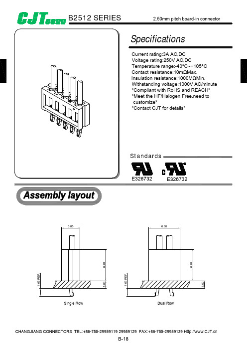
Part NO.
Wire Range
Insulation O.D.
B2512-TB
AWG#22-#28
1.70mm(max)
B2512-TP
AWG#22-#28
1.70mm(max)
B2512-GB
AWG#22-#28
1.70mm(max)
B2512-GP
AWG#22-#28
1.70mm(max)
Optional Gold plating available but MOQ requested
B-18
B2512 SERIES
2.50mm pitch board-in connector
B2512-T
Reference Informations: *Used in CJT B2512H-XP series Housing
2.50mm pitch Crimp Terminal
0.20
2.75±0.25
PART NO.
2x2P 2x3P 2x4P 2x5P 2x6P 2x7P 2x8P 2x9P 2x10P 2x11P 2x12P 2x13P 2x14P 2x15P 2x16P 2x17P 2x18P 2x19P 2x20P
Dimensions
A
B
2.50
5.08
5.00
9.10
7.50
11.60
B2512 SERIES
2.50mm pitch board-in connector
Specifications
Current rating:3A AC,DC Voltage rating:250V AC,DC Temperature range:-40°C~+105°C Contact resistance:10mΩMax. Insulation resistance:1000MΩMin. Withstanding voltage:1000V AC/minute *Compliant with RoHS and REACH* *Meet the HF/Halogen Free,need to customize* *Contact CJT for details*
海哥尔德电子产品简介说明书

APRIL 2013Quick-Refere nce GuideLAPTOP, DESKTO P AND VIDEO STORAGE DRIVESSeagate Partner Program MembersVisit the Sales Tools section to access the latestproduct roadmap, end-of-life schedule and product information. DistributorsEMEA SPP Support00-800-6890-8282US Sales Support1-800-SEAGATE or 1-405-324-4700Visit for more information or call 1-800-SEAGATE (1-800-732-4283) © 2013 Seagate Technology LLC. All rights reserved. Printed in USA. Seagate, Seagate Technology and the Wave logo are registered trademarks of Seagate Technology LLC in the United States and/or other countries. Barracuda, G-Force Protection, Momentus, Pipeline HD, SmartAlign and SV35 Series are either trademarks or registered trademarks of Seagate Technology LLC or one of its affiliated companies in the United States and/or other countries. The FIPS logo is a certification mark of NIST, which does not imply product endorsement by NIST, the U.S., or Canadian governments. All other trademarks or registered trademarks are the property of their respective owners. When referring to drive capacity, one gigabyte, or GB, equals one billion bytes and one terabyte, or TB, equals one trillion bytes. Your computer’s operating system may use a different standard of measurement and report a lower capacity. In addition, some of the listed capacity is used for formatting and other functions, and thus will not be available for data storage. Actual data rates may vary depending on operating environment and other factors. The export or re-export of hardware or software containing encryption may be regulated by the US Department of Commerce, Bureau of Industry and Security (for more information go to ). Seagate reserves the right to change, without notice, product offerings or specifications. QR502.15-1304GB, April 2013APRIL 2013Quick-Reference GuideLAPTOP, DESKTOP AND VIDEO STORAGE DRIVESNew Seagate Model Number KeyDesktop, laptop and video storageST 500 DX 001BRANdCAPACiTySegMeNTATTRiBuTeS2 letters ST= Seagate MX= Maxtor2 to 4 digits 80 = 80GB 500 = 500GB 1500 = 1,500GB Capacities>9,999GB: 10 = 10TB 15 = 15TB2 lettersDX = Desktop Premium DM = Mainstream DL = Entry LevelLX = Laptop Premium LM = Laptop Mainstream LT = Laptop Thin VX = Surveillance VM = DVR VT = DVR Thin3 digits, non-intelligent Varies for:Z-height Form Factor RPM Cache Interface SED, FIPS Drop Sensor Interface SpeedView a brief training presentation on how our model numbering format has changed at /seagate/ModelNumber 1 One gigabyte, or GB, equals one billion bytes; and one terabyte, or TB, equals one trillion bytes when referring to drive capacity.2See FIPS 140-2 Level 2 Certificate at /groups/STM/cmvp/documents/140-1/1401vend.htm.37mm z-height expanded to 9.5mm enables compatibility with standard laptop chassis.4Advanced Format 4K sector drive with SmartAlign ™ technology resolves misalignment conditions.5Seagate makes this drive in both 4K and 512-byte sectors. SmartAlign technology is included on 4K sector drives. Both drives are functionally and physically equivalent.6Formerly Barracuda ®drive。
thip2500中文手册
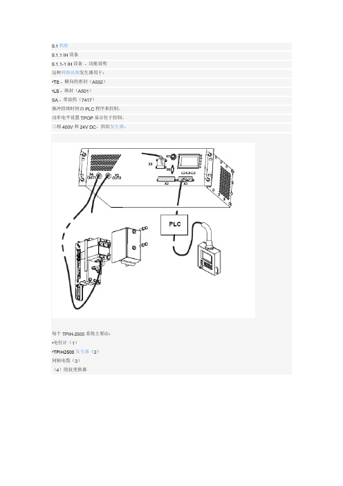
9.1机柜9.1.1 IH设备9.1.1-1 IH设备- 功能说明这种两路高频发生器用于:•TS - 横向的密封(A502)•LS - 纵封(A501)SA - 带涂药(7417)脉冲持续时间由PLC程序来控制。
功率电平设置TPOP显示位于控制。
三相400V和24V DC,供给发生器。
每个TPIH-2500系统主要由:•电位计(1)•TPIH2500发生器(2)同轴电缆(3)(4)阻抗变换器1电位2 TPIH2500发生器3同轴电缆4阻抗变压器TPIH2500发生器主要由:•输出1 X4(5)•输出2 X5(6)•串行连接5233(7)•24V连接X3(8)•400V连接X1(9)•多功能按钮(10)•LED状态指示灯(11)•液晶显示器(12)5输出16输出27串行连接8 24V连接9 400V连接10多功能按钮11 LED液晶显示器(LCD)12LED的描述有触电的危险!当400VAC绿色指示灯熄灭仍然可以有一个或两个连接器X1阶段上。
彩色标签含义绿色24 VDC,当有24v时24 V时。
它关闭时,没有24。
绿色400 VAC当所有3相存在。
为OFF时,至少错过了一个3相。
红色错误是ON时,一个或多个错误发生。
在这种情况下,上液晶显示,操作员可以读取错误发生。
为OFF时,有没有错误条件。
绿色输出1而发电机是通过发送功率输出1为ON为OFF时,输出1为无效。
绿色输出2这是ON而发电机是通过发送功率输出2OFF输出时是无效的。
危险!9.1.1-2 IH设备-LCD显示器用户菜单TPIH2500为用户提供了一个简单的方法访问许多通过在显示屏上显示的菜单中的信息和设置。
一个普通的页面通常是由三部分组成:排在顶部显示网页标题,•以下六个行可以显示命令或信息,•在底部显示的行执行的操作按钮。
每个按钮上的符号或文字说明行动将如果相同的按钮被按下。
在左边的页面有可能的命令的列表。
当前选定的显示命令反向模式(黑底白字)。
注塑机用超级单元(大金) 说明书
1.2
注塑机用超级单元与SUT系列超级单元的其他产品相比,其模拟输入规格有所不同,故必须使用我公司独创的可变速电机驱动IPM(*1)液压系统才能作为注塑机的液压动力源,根据注塑机发出的模拟指令电压,利用泵的转数控制排量(Q)和压力(P)。
*9.我公司推荐的滤波器使用时的代表值。
2.2.2
下记数据是代表性能,并非保证值。
项目
规格
流量特性
直线性
F.S.2%
磁滞
F.S.2%
最大流量响应(*1)
0.10s
重复再现性
F.S.2%
噪声等级(*3)
74.8[dB](流量为80L/min时)
压力特性
直线性
F.S.2%
磁滞
F.S.2%
最大压力响应(*2)
模拟输入
(2ch)
指令分解能 1.0%
压力指令Pi
0~+10V
流量指令Qi
0~+10V
模拟输出
(2ch)
压力监控Po
0~+10V
流量监控Qo
-10~+10V
数字输入信号
(*4)
(8ch)
光耦合绝缘DC+24V(最大27V) 5mA/ch
正的共用接点・负的共用接点
DI1
运转停止信号
DIN2~8
(未使用)
因此、有必要充分考虑装载本产品的注塑机的负荷条件、运转周期等。
即使在电源电压容许变动幅度的公差内,若变动为-侧的话,输出特性也有可能下降。
如果担心电源电压变动至380V以下的话,请参考下记代表特性选定要使用的PQ范围。
USB2512中文资料

Low power operation Full Power Management with individual or ganged
power control of each downstream port On-chip Power On Reset (POR) Internal 1.8V Voltage Regulator Fully integrated USB termination and Pull-up/Pull-
Select the presence of a permanently hardwired USB peripheral device on a port by port basis
Configure the delay time for filtering the over-current sense inputs
80 ARKAY DRIVE, HAUPPAUGE, NY 11788 (631) 435-6000, FAX (631) 273-3123
Copyright © 2007 SMSC or its subsidiaries. All rights reserved.
Circuit diagrams and other information relating to SMSC products are included as a means of illustrating typical applications. Consequently, complete information sufficient for construction purposes is not necessarily given. Although the information has been checked and is believed to be accurate, no responsibility is assumed for inaccuracies. SMSC reserves the right to make changes to specifications and product descriptions at any time without notice. Contact your local SMSC sales office to obtain the latest specifications before placing your product order. The provision of this information does not convey to the purchaser of the described semiconductor devices any licenses under any patent rights or other intellectual property rights of SMSC or others. All sales are expressly conditional on your agreement to the terms and conditions of the most recently dated version of SMSC's standard Terms of Sale Agreement dated before the date of your order (the "Terms of Sale Agreement"). The product may contain design defects or errors known as anomalies which may cause the product's functions to deviate from published specifications. Anomaly sheets are available upon request. SMSC products are not designed, intended, authorized or warranted for use in any life support or other application where product failure could cause or contribute to personal injury or severe property damage. Any and all such uses without prior written approval of an Officer of SMSC and further testing and/or modification will be fully at the risk of the customer. Copies of this document or other SMSC literature, as well as the Terms of Sale Agreement, may be obtained by visiting SMSC’s website at . SMSC is a registered trademark of Standard Microsystems Corporation (“SMSC”). Product names and company names are the trademarks of their respective holders.
海尔磁盘系列说明书
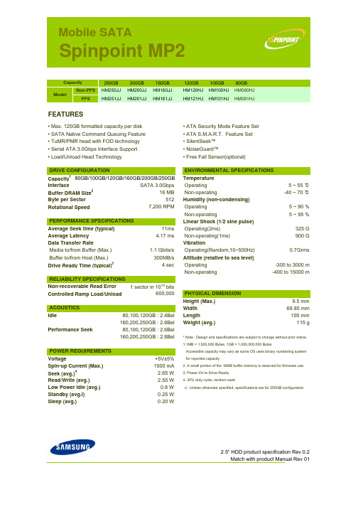
Mobile SATASpinpoint MP2250GB200GB 160GB120GB 100GB 80GB Non-FFS HM250JJ HM200JJ HM160JJ HM120HJ HM100HJ HM080HJ FFSHM251JJHM201JJHM161JJHM121HJHM101HJHM081HJFEATURES• Max. 125GB formatted capacity per disk • ATA Security Mode Feature Set • SATA Native Command Queuing Feature • ATA S.M.A.R.T. Feature Set • TuMR/PMR head with FOD technology • SilentSeek™ • Serial ATA 3.0Gbps Interface Support • NoiseGuard™• Load/Unload Head Technology• Free Fall Sensor(optional)Capacity 180GB/100GB/120GB/160GB/200GB/250GBTemperature InterfaceSATA 3.0Gbps Operating 5 ~ 55 ℃Buffer DRAM Size216 MB Non-operating -40 ~ 70 ℃Byte per Sector512Humidity (non-condensing)Rotational Speed7,200 RPM Operating 5 ~ 90 % Non-operating 5 ~ 95 %Linear Shock (1/2 sine pulse)Average Seek time (typical)11msOperating(2ms)325 G Average Latency 4.17 ms Non-operating(1ms)900 G Data Transfer RateVibrationMedia to/from Buffer (Max.) 1.1 Gbits/s Operating(Random,10~500Hz)0.7Grms Buffer to/from Host (Max.)300MB/sAltitude (relative to sea level)Drive Ready Time (typical)34 secOperating -300 to 3000 m Non-operating -400 to 15000 mNon-recoverable Read Error 1 sector in 1014bitsControlled Ramp Load/Unload 600,000Height (Max.)9.5 mm Width 69.85 mm Idle80,100,120GB : 2.4Bel Length100 mm 160,200,250GB : 2.6Bel Weight (avg.)115 gPerformance Seek80,100,120GB : 2.6Bel 160,200,250GB : 2.8Bel* Note : Design and specifications are subject to change without prior notice.1.1MB = 1,000,000 Bytes, 1GB = 1,000,000,000 BytesAccessible capacity may vary as some OS uses binary numbering systemVoltage+5V±5% for reported capacitySpin-up Current (Max.)1000 mA 2. A small portion of the 16MB buffer memory is reserved for firmware use.Seek (avg.)42.65 W3. Power-On to Drive Ready Read/Write (avg.)2.55 W 4. 30% duty cycle, random seekLow Power Idle (avg.)0.8 W ※. Unless otherwise specified, specifications are for 250GB configurationStandby (avg.l)0.25 W Sleep (avg.)0.20 W2.5" HDD product specification Rev 0.2Match with product Manual Rev 01ENVIRONMENTAL SPECIFICATIONS PERFORMANCE SPECIFICATIONSRELIABILITY SPECIFICATIONS PHYSICAL DIMENSION POWER REQUIREMENTS ACOUSTICSCapacity DRIVE CONFIGURATIONModel。
- 1、下载文档前请自行甄别文档内容的完整性,平台不提供额外的编辑、内容补充、找答案等附加服务。
- 2、"仅部分预览"的文档,不可在线预览部分如存在完整性等问题,可反馈申请退款(可完整预览的文档不适用该条件!)。
- 3、如文档侵犯您的权益,请联系客服反馈,我们会尽快为您处理(人工客服工作时间:9:00-18:30)。
CDHV 2512
Vishay Techno
Document Number:
High Voltage Chip Divider
FEATURES
•High voltage up to 3000 volts •Outstanding Stability
•Typical resistance ratios of 250:1, 500:1, etc •Flow solderable
•Tape & Reel packaging available •Top and Wraparound termination
•
Nickel Barrier available
ELECTRICAL SPECIFICATIONS
Resistance range: 1 M Ω to 20 G ΩResistance tolerance: ± 1 % to ± 20 %Power rating: See table Voltage coefficient: See table Temperature coefficient: See table Ratio tracking: See table
MECHANICAL SPECIFICATIONS
Construction: 96 % alumina substrate with proprietary cermet resistance element and specified termination material.
ENVIRONMENTAL SPECIFICATIONS
Operating temperature: - 55 °C to + 150 °C
Life: Less than 0.5 % change when tested at full rated power
(Reference only: Not for all values specified. Consult factory for value.)
STANDARD ELECTRICAL SPECIFICATIONS
RESISTANCE (OHMS)
POWER RATING (MW)
VOLTAGE RATING (V MAX)
20 M - 20 G
Contact Factory
3000
VOLTAGE & TEMPERATURE COEFFICIENTS OF RESISTANCE CHART TYPICAL
RESISTANCE (OHMS)
RATIO (TYPICAL)
VCR (PPM/V)
TCR
(PPM/°C) - 55 °C to + 150 °C
20 M 250:15260150 M 300:1580800 M 300:1105020 G
700:1
90
160
RATIO TRACKING (PPM/°C)
RESISTANCE (OHMS)
RATIO (TYPICAL)
COLD (+ 25 °C to - 50 °C)
HOT (+ 25 °C to + 150 °C)
20 M 250:15260150 M 300:1580800 M 300:1105020 G
700:1
90
160
*** Contact Factory for other Ratio’s
ORDERING INFORMATION
CDHV2512A A2005J2500G e1
MODEL TERMINA TION
STYLE TERMINA TION
MA TERIAL
VALUE
R1
ABSOLUTE
TOLERANCE
RA TIO
R1/R2
RA TIO
TOLERANCE
TERMINA TION
MA TERIAL
A = Wraparound
B = T op only A = Palladium Silver
B = Platinum Gold
C = Gold
D = Platinum Silver
E = Palladium Gold
F = Nickel Barrier
Resistance Value of R1:
The first 3 digits are
significant. The last digit
specifies the number of
zeros to follow.
F = 1 %
G = 2 %
H = 3 %
J = 5 %
K = 10 %
M = 20 %
The first 3 digits
are significant.
The last digit
specifies the
number of zeros to
follow.
F = 1 %
G = 2 %
H = 3 %
J = 5 %
S2 = Sn62
e1 = Sn95/5
Document Number: 68020
Legal Disclaimer Notice
Vishay
Notice
Specifications of the products displayed herein are subject to change without notice. Vishay Intertechnology, Inc., or anyone on its behalf, assumes no responsibility or liability for any errors or inaccuracies.
Information contained herein is intended to provide a product description only. No license, express or implied, by estoppel or otherwise, to any intellectual property rights is granted by this document. Except as provided in Vishay's terms and conditions of sale for such products, Vishay assumes no liability whatsoever, and disclaims any express or implied warranty, relating to sale and/or use of Vishay products including liability or warranties relating to fitness for a particular purpose, merchantability, or infringement of any patent, copyright, or other intellectual property right. The products shown herein are not designed for use in medical, life-saving, or life-sustaining applications. Customers using or selling these products for use in such applications do so at their own risk and agree to fully indemnify Vishay for any damages resulting from such improper use or sale.。
