183426ds_k4s64xx32n_rev111
维沙易 Siliconix S11-2419-Rev. C 自动车双渣道 40V 175°C MOS

Automotive Dual N-Channel 40 V (D-S) 175 °C MOSFETFEATURES•Halogen-free According to IEC 61249-2-21Definition•TrenchFET ® Power MOSFET •AEC-Q101 Qualified d•100 % R g and UIS Tested•Compliant to RoHS Directive 2002/95/ECNotesa.Package limited.b.Pulse test; pulse width ≤ 300 μs, duty cycle ≤ 2 %.c.When mounted on 1" square PCB (FR4 material).d.Parametric verification ongoing.e.See solder profile (/doc?73257). The PowerPAK SO-8L. The end of the lead terminal is exposed copper (not plated) as a result of the singulation process in manufacturing. A solder fillet at the exposed copper tip cannot be guaranteed and is not required to ensure adequate bottom side solder interconnection..f.Rework conditions: manual soldering with a soldering iron is not recommended for leadless components.PRODUCT SUMMARYV DS (V)40R DS(on) (Ω) at V GS = 10 V 0.020R DS(on) (Ω) at V GS = 4.5 V 0.028I D (A) per leg 8ConfigurationDualORDERING INFORMATIONPackagePowerPAK SO-8L Lead (Pb)-free and Halogen-freeSQJ970EP-T1-GE3ABSOLUTE MAXIMUM RATINGS (T C = 25 °C, unless otherwise noted)PA AMETE SYMBOL LIMIT UNIT Drain-Source Voltage V DS40VGate-Source Voltage V GS ± 20Continuous Drain Current aT C = 25 °C I D 8A T C = 125 °C8Continuous Source Current (Diode Conduction)a I S 8Pulsed Drain Current bI DM 32Single Pulse Avalanche Current L = 0.1 mH I AS 28Single Pulse Avalanche Energy E AS 39mJ Maximum Power Dissipation bT C = 25 °C P D 48W T C = 125 °C 16Operating Junction and Storage Temperature Range T J , T stg- 55 to + 175°C Soldering Recommendations (Peak Temperature)e, f260THERMAL RESISTANCE RATINGSPA AMETE SYMBOL LIMIT UNIT Junction-to-Ambient PCB Mount cR thJA 85°C/WJunction-to-Case (Drain)R thJC3.1Notesa.Pulse test; pulse width ≤ 300 μs, duty cycle ≤ 2 %.b.Guaranteed by design, not subject to production testing.c.Independent of operating temperature.Stresses beyond those listed under “Absolute Maximum Ratings” may cause permanent damage to the device. These are stress ratings only, and functional operation of the device at these or any other conditions beyond those indicated in the operational sections of the specifications is not implied. Exposure to absolute maximum rating conditions for extended periods may affect device reliability.SPECIFICATIONS (T C = 25 °C, unless otherwise noted)PA AMETE R SYMBOLTEST CONDITIONS MIN.TYP.MAX.UNITStaticDrain-Source Breakdown Voltage V DS V GS = 0, I D = 250 μA 40--V Gate-Source Threshold Voltage V GS(th)V DS = V GS , I D = 250 μA 1.5 2.0 2.5Gate-Source LeakageI GSS V DS = 0 V, V GS = ± 20 V--± 100nAZero Gate Voltage Drain Current I DSS V GS = 0 V V DS = 40 V --1μA V GS = 0 V V DS = 40 V, T J = 125 °C --50V GS = 0 V V DS = 40 V, T J = 175 °C--150On-State Drain Current aI D(on)V GS = 10 V V DS ≥ 5 V 30--A Drain-Source On-State Resistance aR DS(on)V GS = 10 VI D = 10.2 A -0.0160.020ΩV GS = 4.5 V I D = 8.7 A-0.0220.028V GS = 10 V I D = 10.2 A, T J = 125 °C -0.0250.031V GS = 10 VI D = 10.2 A, T J = 175 °C-0.0290.036Forward Transconductance b g fsV DS = 15 V, I D = 10.2 A-28-S Dynamic bInput Capacitance C issV GS = 0 V V DS = 20 V, f = 1 MHz -17302165pFOutput CapacitanceC oss -260325Reverse Transfer Capacitance C rss -130165Total Gate Charge c Q gV GS = 10 V V DS = 20 V, I D = 10.2 A -3455nC Gate-Source Charge c Q gs - 5.2-Gate-Drain Charge c Q gd - 6.5-Gate Resistance R g f = 1 MHz0.71 3.927.12ΩTurn-On Delay Time c t d(on)V DD = 20 V, R L = 20 ΩI D ≅ 1 A, V GEN = 10 V, R g = 1 Ω-1015ns Rise Time ct r-812Turn-Off Delay Time c t d(off) -5075Fall Time c t f -1015Source-Drain Diode Ratings and Characteristics bPulsed Current a I SM --32A Forward VoltageV SDI F = 2.9 A, V GS = 0-0.81.1VTYPICAL CHARACTERISTICS(T ATransfer Characteristics Capacitance Transfer Characteristics TransconductanceGate ChargeTYPICAL CHARACTERISTICS(T A = 25 °C, unless otherwise noted)On-Resistance vs. Drain Current Source Drain Diode Forward Voltage On-Resistance vs. Junction Temperature Drain-Source Breakdown vs. Junction Temperature On-Resistance vs. Gate-to-Source VoltageThreshold VoltageTHERMAL RATINGS(T A = 25 °C, unless otherwise noted)Safe Operating AreaTHERMAL RATINGS(T A = 25 °C, unless otherwise noted)Normalized Thermal Transient Impedance, Junction-to-CaseNote•The characteristics shown in the two graphs- Normalized Transient Thermal Impedance Junction-to-Ambient (25 °C)- Normalized Transient Thermal Impedance Junction-to-Case (25 °C)are given for general guidelines only to enable the user to get a “ball park” indication of part capabilities. The data are extracted from single pulse transient thermal impedance characteristics which are developed from empirical measurements. The latter is valid for the part mounted on printed circuit board - FR4, size 1" x 1" x 0.062", double sided with 2 oz. copper, 100 % on both sides. The part capabilities can widely vary depending on actual application parameters and operating conditions.Vishay Silico nix maintains wo rldwide manufacturing capability. Pro ducts may be manufactured at o ne o f several qualified lo catio ns. Reliability data fo r Silico n Technology and Package Reliability represent a composite of all qualified locations. For related documents such as package/tape drawings, part marking, and reliability data, see /ppg?65282.Legal Disclaimer Notice VishayDisclaimerALL PRODU CT, PRODU CT SPECIFICATIONS AND DATA ARE SU BJECT TO CHANGE WITHOU T NOTICE TO IMPROVE RELIABILITY, FUNCTION OR DESIGN OR OTHERWISE.Vishay Intertechnology, Inc., its affiliates, agents, and employees, and all persons acting on its or their behalf (collectively,“Vishay”), disclaim any and all liability for any errors, inaccuracies or incompleteness contained in any datasheet or in any other disclosure relating to any product.Vishay makes no warranty, representation or guarantee regarding the suitability of the products for any particular purpose or the continuing production of any product. To the maximum extent permitted by applicable law, Vishay disclaims (i) any and all liability arising out of the application or use of any product, (ii) any and all liability, including without limitation special, consequential or incidental damages, and (iii) any and all implied warranties, including warranties of fitness for particular purpose, non-infringement and merchantability.Statements regarding the suitability of products for certain types of applications are based on Vishay’s knowledge of typical requirements that are often placed on Vishay products in generic applications. Such statements are not binding statements about the suitability of products for a particular application. It is the customer’s responsibility to validate that a particular product with the properties described in the product specification is suitable for use in a particular application. Parameters provided in datasheets and/or specifications may vary in different applications and performance may vary over time. All operating parameters, including typical parameters, must be validated for each customer application by the customer’s technical experts. Product specifications do not expand or otherwise modify Vishay’s terms and conditions of purchase, including but not limited to the warranty expressed therein.Except as expressly indicated in writing, Vishay products are not designed for use in medical, life-saving, or life-sustaining applications or for any other application in which the failure of the Vishay product could result in personal injury or death. Customers using or selling Vishay products not expressly indicated for use in such applications do so at their own risk. Please contact authorized Vishay personnel to obtain written terms and conditions regarding products designed for such applications. No license, express or implied, by estoppel or otherwise, to any intellectual property rights is granted by this document or by any conduct of Vishay. Product names and markings noted herein may be trademarks of their respective owners.Material Category PolicyVishay Intertechnology, Inc. hereby certifies that all its products that are identified as RoHS-Compliant fulfill the definitions and restrictions defined under Directive 2011/65/EU of The European Parliament and of the Council of June 8, 2011 on the restriction of the use of certain hazardous substances in electrical and electronic equipment (EEE) - recast, unless otherwise specified as non-compliant.Please note that some Vishay documentation may still make reference to RoHS Directive 2002/95/EC. We confirm that all the products identified as being compliant to Directive 2002/95/EC conform to Directive 2011/65/EU.Vishay Intertechnology, Inc. hereby certifies that all its products that are identified as Halogen-Free follow Halogen-Free requirements as per JEDEC JS709A standards. Please note that some Vishay documentation may still make reference to the IEC 61249-2-21 definition. We confirm that all the products identified as being compliant to IEC 61249-2-21 conform to JEDEC JS709A standards.。
德国制造的4位数字数字显示压力传感器说明书

1:4-digit alphanumeric display 2:LEDs3:Programming buttonMade inGermanyProduct characteristics Combined pressure sensor ConnectorProcess connection:G 1A /Aseptoflex Vario Display units:bar,psi,MPa,%of the span Function programmable2-wire connection technology:analogue output3-wire connection technology:2outputsOUT1=switching outputOUT2=switching output or analogue output 4-digit alphanumeric displayMeasuring range:-1.00...10.00bar /-14.5...145.0psi /-0.100...1.000MPa Application Type of pressure:relative pressureHygienic systems,viscous media and liquids with suspended particlesLiquids and gasesApplication5MPa 725psi 50bar Pressure rating 15MPa 2175psi 150bar Bursting pressure min.5MPa725psi50barMAWP (for applications according to CRN)-25...125(145max.1h)Medium temperature [°C]Electrical data 2wires DC /3wires DC PNP/NPNElectrical design 20...32DC (2L)/18...32DC (3L)Operating voltage [V] 3.6...21(2L)/<45(3L)Current consumption [mA]>100(500V DC)Insulation resistance[MΩ]III Protection classyesReverse polarity protection Outputs 2-wire connection technology:analogue output3-wire connection technology:2outputsOUT1=switching outputOUT2=switching output or analogue outputOutput1x normally open /normally closed programmable +1x normally open /normallyclosed programmable or 1x analogue (4...20/20...4mA,scalable)Output function ---(2L)/250(3L)Current rating [mA]---(2L)/<2(3L)Voltage drop[V]pulsed Short-circuit protection yesOverload protection ---(2L)/125(3L)Switching frequency [Hz]I:4...20mA (Ineg:20...4mA)Analogue output 300(2L)/max.(Ub -10V)x 50(3L)Max.load[Ω]Measuring /setting range -0.100...1.000MPa -14.5...145.0psi -1.00...10.00bar Measuring range Setting range -0.098...1.000MPa -14.2...145.0psi -0.98...10.00bar Set point,SP -0.100...0.998MPa -14.5...144.7psi -1.00...9.98bar Reset point,rP-0.100...0.750MPa -14.5...108.7psi -1.00...7.50bar Analogue start point,ASP 0.150...1.000MPa21.8...145.0psi1.50...10.00barAnalogue end point,AEP 0.001MPa0.1psi0.01barin steps of SP1=2.50bar;rP1=2.30bar SP2=7.50bar;rP2=7.30bar ASP =0.00bar;AEP =10.00barFactory settingAccuracy /deviations Accuracy /deviations(in %of the span)Turn down 1:1<±0.2Switch point accuracy <±0.2Characteristics deviation *)<±0.15Linearity <±0.15Hysteresis <±0.1Repeatability **)<±0.1Long-term stability ***)Temperature coefficients (TEMPCO)in the temperature range 0...70°C (in %of the span per 10K)<±0.05Greatest TEMPCO of the zero point <±0.15Greatest TEMPCO of the span Reaction times 1(2L)/0.5(3L)Power-on delay time [s]---(2L)/3(3L)Min.response time switching output[ms]0.00...30.00Damping for the switching output (dAP)[s]0.01...99.99Damping for the analogue output (dAA)[s]45(2L)/7(3L)Step response time analogue output[ms]yesIntegrated watchdog Interfaces IO-Link Device COM2(38.4kBaud)Transfer type 1.0IO-Link revision 157d /00009D hIO-Link Device ID no profile Profiles yes SIO modeA Required master port type 1Process data analogue 2Process data binary 2.3Min.process cycle time [ms]Environment -25...80Ambient temperature [°C]-40...100Storage temperature [°C]IP 67/IP 68/IP 69KProtection Tests /approvals EMCDIN EN 61000-6-2DIN EN 61000-6-3Shock resistance 50g (11ms)DIN EN 60068-2-27:Vibration resistance 20g (10...2000Hz)DIN EN 60068-2-6:160MTTF[Years]Mechanical data G 1A /Aseptoflex VarioProcess connection ceramics (99.9%Al2O3);PTFE;stainless steel 316L /1.4435;surfacecharacteristics:Ra <0.4/Rz 4Materials (wetted parts)stainless steel 316L /1.4404;FPM;PTFE;PBT;PEI;PFAHousing materials 100million Switching cycles min.0.313Weight[kg]Displays /operating elements DisplayLED green Display unit LED yellowSwitching status 4-digit alphanumeric display Function display 4-digit alphanumeric displayMeasured values Electrical connection M12connector;Gold-plated contactsConnection Wiring1connection for2-wire operation2connection for3-wire operation3connection for IO-Link parameter setting(P=communication via IO-Link)RemarksRemarks(2L)=value for2-wire operation(3L)=value for3-wire operation*)linearity,incl.hysteresis and repeatability;(limit value setting to DIN16086)**)with temperature fluctuations<10K***)in%of the span per year1Pack quantity[piece]ifm electronic gmbh•Friedrichstraße1•45128Essen—We reserve the right to make technical alterations without prior notice.—GB—PI2794—16.04.2013。
飞思卡尔半导体用户指南说明书

Freescale Semiconductor User’s Guide1OverviewThe Freescale Freedom development platform is a set of software and hardware tools for evaluation and development. It’s ideal for the rapid prototyping ofmicrocontroller-based applications. The Freescale Freedom KL26Z hardware (FRDM-KL26Z) is a capable and cost-effective design featuring a Kinetis L seriesmicrocontroller, the industry’s first microcontroller built on the ARM® Cortex™-M0+ core.FRDM-KL26Z can be used to evaluate the KL16 and KL26 Kinetis L series devices. It features a KL26Z128VLH4, a device boasting a maximum operating frequency of 48MHz, 128KB of flash, a full-speed USB controller, and numerous analog and digital peripherals. The FRDM-KL26Z hardware is form-factor compatible with the Arduino™ R3 pin layout, providing a broad range of expansion board options. The on-board interfaces include an RGB LED, a 6-axis digital sensor (combining a 3D accelerometer and 3Dmagnetometer), ambient light sensor, and a capacitive touch slider.The FRDM-KL26Z features the Freescale open standard embedded serial and debug adapter known as OpenSDA.Doc Number:FRDMKL26ZUGRev. 0, 10/2013Contents1.Overview . . . . . . . . . . . . . . . . . . . . . . . . . . . . . . . . . . . 12.Reference documents . . . . . . . . . . . . . . . . . . . . . . . . . 23.Getting started . . . . . . . . . . . . . . . . . . . . . . . . . . . . . . . 24.FRDM-KL26Z hardware overview . . . . . . . . . . . . . . 25.FRDM-KL26Z hardware description . . . . . . . . . . . . . 5FRDM-KL26Z User’s GuidebyFreescale Semiconductor, Inc.Reference documentsThis circuit offers several options for serial communications, flash programming and run-control debugging.2Reference documentsThe table below provides a list of reference documents for the FRDM-KL26Z hardware. All of these documents are available online at /FRDM-KL26Z.Table1. FRDM-KL26Z reference documentsFilename DescriptionFRDM-KL26Z Quick Start Package Quick Start Guide and supporting files for getting started with the FRDM-KL26Z FRDM-KL26Z User’s Guide This document—overview and detailed information for the FRDM-KL26ZhardwareFRDM-KL26Z Pinouts Spreadsheet of pin connections for all MCU pins. Includes pinout for the I/Oheaders, Arduino R3 compatibility chart, and OpenSDA MCU pinout.FRDM-KL26Z Schematics PDF schematics for the FRDM-KL26Z hardwareFRDM-KL26Z Design Package Zip file containing all design source files for the FRDM-KL26Z hardware OpenSDA User’s Guide Overview and instructions for use of the OpenSDA embedded debug circuit3Getting startedSee the FRDM-KL26Z Quick Start Package for step-by-step instructions to get started with the FRDM-KL26Z. See the Jump Start Your Design section on /FRDM-KL26Z for the Quick Start Package and software lab guides.4FRDM-KL26Z hardware overviewThe features of the FRDM-KL26Z include:•MKL26Z128VLH4 in a 64 LQFP package•Capacitive touch slider•FXOS8700CQ accelerometer and magnetometer•Tri-color (RGB) LED•Ambient light sensor•User push button•Flexible power supply options – USB, coin cell battery, external source•Battery-ready, power-measurement access points•Easy access to MCU I/O via Arduino™ R3 compatible I/O connectors•Programmable OpenSDA debug interface with multiple applications available including:—Mass storage device flash programming interface—P&E Debug interface provides run-control debugging and compatibility with IDE toolsFRDM-KL26Z hardware overview—CMSIS-DAP interface: new ARM standard for embedded debug interface—Data logging applicationFigure1 shows a block diagram of the FRDM-KL26Z design. The primary components and their placement on the hardware assembly are pointed out in Figure2.Figure1. FRDM-KL26Z block diagramFRDM-KL26Z hardware overview! (Figure2. FRDM-KL26Z feature call-outsFRDM-KL26Z hardware description5FRDM ‐KL26Z hardware description5.1Power supplyThere are multiple power supply options on the FRDM-KL26Z. It can be powered from either of the USB connectors, the VIN pin on the I/O header, an on-board coin cell battery, or an off-board 1.71-3.6V supply from the 3.3V pin on the I/O header. The USB and VIN supplies are regulated on-board using a 3.3V linear regulator to produce the main power supply. The other two sources are not regulated on-board. Table 2 provides the operational details and requirements for the power supplies.Table 2.Power supply requirementsNote that the OpenSDA circuit is only operational when a USB cable is connected and supplying power to J10. However, protection circuitry is in place to allow multiple sources to be powered at once.Figure 3 shows the schematic drawing for the power supply inputs and the on-board voltage regulator.Figure 3. Power supply schematicIn addition, regulated power can be supplied to J3 pin 10 from an external source through P5-9V_VIN by populating the board with an optional voltage regulator, e.g. a 7805 style regulator in a TO-220 package, thus providing a high current supply to external devices. To prevent voltage sag under a high load, C23,Supply Source Valid RangeOpenSDA Operational?Regulated on-board?OpenSDA USB (J7)5V Yes Yes KL26Z USB (J5)5V No Yes V in 4.3-9V No Yes 3.3V pin 1.71-3.6V No No Coin cell battery1.71-3.6VNoNoFRDM-KL26Z hardware descriptionC24, C25 & C28 should be populated with appropriately sized capacitors to match the regulator chosen. See Figure4.Figure4. Optional voltage regulator schematicTable3. FRDM-KL26Z power suppliesPowerDescriptionSupply NameP5-9V_VIN Power supplied from the V in pin of the I/O headers (J3 pin 16)P5V_SDA Power supplied from the OpenSDA USB connector (J10). A Schottky diode provides back drive protection.P5V_KL26Z Power supplied from the KL26Z USB connector (J6). A Schottky diode provides back drive protection P3V3_VREG Regulated 3.3V supply. Sources power to the P3V3 supply rail with an optional back drive protection Schottky diode.12P3V3_BATT Coin cell battery supply voltage. Sources power to the P3V3 supply rail with the option of adding a back drive protection Schottky diode.3P3V3Main supply rail for the FRDM-KL26Z assembly. May be sourced from P3V3_VREG, P3V3_BATT, or directly from the I/O headers (J3 pin 8).P3V3_KL26Z KL26Z MCU supply. Header J5 provides a convenient means for energy consumption measurements.4 P3V3_SDA OpenSDA circuit supply. Header J15 provides a convenient means for energy consumptionmeasurements.4P5V_USB Nominal 5V supplied to the I/O headers (J3 pin 10). Sourced from either the P5V_KL26Z or P5V_SDA supply through a back drive protection Schottky diode.FRDM-KL26Z hardware description5.2Serial and debug adapter (OpenSDA)OpenSDA is an open standard serial and debug adapter. It bridges serial and debug communications between a USB host and an embedded target processor as shown in Figure 5. The hardware circuit is based on a Freescale Kinetis K20 family microcontroller (MCU) with 128 KB of embedded flash and anintegrated USB controller. OpenSDA features a mass storage device (MSD) bootloader, which provides a quick and easy mechanism for loading different OpenSDA applications such as flash programmers, run-control debug interfaces, serial-to-USB converters, and more. See the OpenSDA User’s Guide for more details.Figure 5. OpenSDA high-level block diagramOpenSDA is managed by a Kinetis K20 MCU built on the ARM® Cortex™-M4 core. The OpenSDA circuit includes a status LED (D8) and a pushbutton (SW2). The pushbutton asserts a reset signal to the KL26Z target MCU. It can also be used to place the OpenSDA circuit into Bootloader mode. OpenSDA MCU RESET can be isolated from SW2 by cutting the trace between pins on J13. SPI and GPIO signals1By default the linear regulator, U1, is a 3.3V output regulator. However, this is a common footprint that would allow the user to modify the assembly to utilize an alternative device such as a 1.8V or 2.5V regulator. The KL26Z microcontroller has an operating range of 1.71V to 3.6V.2D2 is bypassed by J14. By default, the pins of J14 are shorted together, to reduce the voltage drop across D2. To use D2, cut the trace between the pins of J14.3If a coin cell battery is to be used, add a small amount of solder to the coin cell ground pad before adding the battery holder. Also, it is recommended to populate D1 as a protection diode when using a coin cell battery.4J5 and J15 are not populated by default. The two pins of these headers are in parallel with 0 Ω resistors. In addition, J5 is also in parallel with a 10 Ω resistor. To measure the energy consumption of the KL26Z, either a voltmeter or an ammeter may be used. To use a voltmeter, R3 (0 Ω) must be removed before connecting the voltmeter probes to the pins of J5. Both R3 and R2 (10 Ω) must be removed to measure current with an ammeter. For the OpenSDA MCU, energy consumption can be measured by removing R4 (0 Ω) and connecting ammeter probes to the pins of J15.FRDM-KL26Z hardware descriptionprovide an interface to the SWD debug port of the KL26Z. Additionally, signal connections are available to implement a UART serial channel. The OpenSDA circuit receives power when the USB connector J10 is plugged into a USB host.5.2.1Debug interfaceSignals with SPI and GPIO capability are used to connect directly to the SWD of the KL26Z. These signals are also brought out to a standard 10-pin (0.05”) Cortex Debug connector (J7). It is possible to isolate the KL26Z MCU from the OpenSDA circuit and use J7 to connect to an off-board MCU. To accomplish this, cut the trace on the bottom side of the PCB that connects J8 pin 1 to J8 pin 2. This will disconnect the SWD_CLK pin to the KL26Z so that it will not interfere with the communications to an off-board MCU connected to J7.Figure6. SWD debug connectorNote that J7 is not populated by default. A Samtec FTSH-105-02-F-D or compatible connector can be added to the J7 through-hole connector. A mating cable, such as a Samtec FFSD IDC cable, can then be used to connect from the OpenSDA of the FRDM-KL26Z to an off-board SWD connector.5.2.2Virtual serial portA serial port connection is available between the OpenSDA MCU and pins PTA1 and PTA2 of the KL26Z. Several of the default OpenSDA Applications provided by Freescale, including the MSD Flash Programmer and the P&E Debug Application, provide a USB communications device class (CDC) interface that bridges serial communications between the USB host and this serial interface on the KL26Z.5.3KL26Z microcontrollerThe target microcontroller of the FRDM-KL26Z is the KL26Z128VLH4, a Kinetis L series device in a 64 LQFP package. The KL26Z MCU features include:FRDM-KL26Z hardware description•32-bit ARM Cortex-M0+ core—Up to 48 MHz operation—Single-cycle fast I/O access port•Memories—128 KB flash—16 KB SRAM•System integration—Power management and mode controllers—Low-leakage wakeup unit—Bit manipulation engine for read-modify-write peripheral operations—Direct memory access (DMA) controller—Computer operating properly (COP) Watchdog timer•Clocks—Clock generation module with FLL and PLL for system and CPU clock generation—4 MHz and 32 kHz internal reference clock—System oscillator supporting external crystal or resonator—Low-power 1kHz RC oscillator for RTC and COP watchdog•Analog peripherals—16-bit SAR ADC w/ DMA support—12-bit DAC w/ DMA support—High speed comparator•Communication peripherals—Two 16-bit Serial Peripheral Interfaces (SPI)—USB dual-role controller with built-in FS/LS transceiver—USB voltage regulator—Two I2C modules—One low-power UART and two standard UART modules—One I2S module•Timers—One 6-channel Timer/PWM module—T wo 2-channel Timer/PWM modules—2-channel Periodic Interrupt Timer (PIT)—Real time clock (RTC)—Low-power Timer (LPTMR)—System tick timer•Human-Machine Interfaces (HMI)—General purpose input/output controllerFRDM-KL26Z hardware description—Capacitive touch sense input interface hardware module5.3.1Clock sourceThe Kinetis KL26 microcontrollers feature an on-chip oscillator compatible with three ranges of input crystal or resonator frequencies: 32-40 kHz (low freq. mode), 3-8 MHz (high frequency mode, low range) and 8-32 MHz (high frequency mode, high range). The KL26Z128 on the FRDM-KL26Z is clocked from an 8 MHz crystal.5.3.2USB interfaceThe Kinetis KL26 microcontrollers feature a dual-role USB controller with on-chip full-speed andlow-speed transceivers. The USB interface on the FRDM-KL26Z is configured as a full-speed USB device. J6 is the USB connector for this interface.Figure7. USB connector schematicIn order to enable USB host functionality on the FRDM-KL26Z, it is necessary to populate J9 and R8 as shown in Figure7. However, there is no electrical protection provided. Use the USB host functionality at your own risk.FRDM-KL26Z hardware description 5.3.3Serial portThe primary serial port interface signals are PTA1 and PTA2. These signals are connected to both the OpenSDA and to the J1 I/O connector. Note that the OpenSDA connection can be isolated from J1 by removing R13 & R14, if required.5.3.4ResetThe PTA20/RESET signal on the KL26Z128 is connected externally to a pushbutton, SW2, and also to the OpenSDA circuit. However, J13 has been provided to isolate the OpenSDA MCU from SW2. Isolating the RESET line allows a more accurate measurement of the target device’s power consumption in low-power modes. The reset button can be used to force an external reset event in the target MCU. The reset button can also be used to force the OpenSDA circuit into bootloader mode. See Section5.2, “Serial and debug adapter (OpenSDA), for more details.5.3.5DebugThe sole debug interface on all Kinetis L Series devices is a serial wire debug (SWD) port. The primary controller of this interface on the FRDM-KL26Z is the onboard OpenSDA circuit (see Section5.2, “Serial and debug adapter (OpenSDA)). However, an unpopulated 10-pin (0.05”) Cortex Debug connector, J7, provides access to the SWD signals. The Samtec FTSH-105-02-F-D or compatible connector can be added to the J7 through-hole debug connector to allow for an external debug cable to be connected.5.4Capacitive touch sliderTwo Touch Sense Input (TSI) signals, TSI0_CH9 and TSI0_CH10, are connected to capacitive electrodes configured as a touch slider. Freescale’s Touch Sense Software (TSS) provides a software library for implementing the capacitive touch slider.5.56-axis accelerometer and magnetometerA Freescale FXOS8700CQ low-power, six-axis accelerometer and magnetometer is interfaced through an I2C bus and two GPIO signals as shown in Table4. By default, the I2C address is 0x1D (SA0 pulled high).Table4. Accelerometer signal connectionsFX0S8700CQ KL26Z128SCL PTE24SDA PTE25INT1PTD0INT2PTD1FRDM-KL26Z hardware descriptionFigure 8. FXOS8700CQ schematic diagram5.6RGB LEDThree PWM-capable signals are connected to a red, green, blue LED, D7. The signal connections are shown in Table 5.Table 5. RGB LED signal connectionsFigure 9. RGB LED schematic diagramRGB LEDKL26Z128Red cathodePTE29Green cathodePTE31Blue cathodePTD511PTD5 is also connected to the I/O header on J2 pin 10 (also known as D13).FRDM-KL26Z hardware description5.7Ambient light sensorAn ambient light sensor is connected to ADC0_SE3 (PTE22). This sensor may be isolated from PTE22 by removing R36.5.8Input/Output connectorsThe KL26Z128VLK4 microcontroller is packaged in a 64-pin LQFP. Some pins are utilized in on-board circuitry, but many are directly connected to one of four I/O headers.The pins on the KL26Z microcontroller are named for their general purpose input/output port pin function. For example, the 1st pin on Port A is referred to as PTA1. The I/O connector pin names are given the same name as the KL26Z pin connected to it, where applicable.FRDM-KL26Z hardware descriptionNote that all pinout data is available in spreadsheet format in FRDM-KL26Z Pinouts. See Section2, “Reference documents” for details.5.9Analog reference voltageThe onboard ADC of the KL26Z128VLH4 MCU uses the Reference V oltage High (VREFH) and Reference V oltage Low (VREFL) pins to set high and low voltage references for the analog modules. On the FRDM-KL26Z, by default VREFH is attached to P3V3_KL26Z (3.3V Supply). VREFL is connected to GND. Figure10 illustrates this circuitry.Figure10. FRDM-KL26Z VREFH circuit schematicIf desired, VREFH can use a VDDA independent reference by adding R11 and a Zener diode (D6). R10 (0 Ω resistor) must be removed when implementing this option. Alternatively, VREFH can be attached to an external source through AREF by removing R10 and populating R9 with a 0 Ω resistor.5.10Arduino compatibilityThe I/O headers on the FRDM-KL26Z are arranged to allow compatibility with peripheral boards (known as shields) that connect to Arduino™ and Arduino-compatible microcontroller boards. The outer rows of pins (the even numbered pins) on the headers share the same mechanical spacing and placement as the I/O headers on the Arduino Revision 3 (R3) standard.FRDM-KL26Z hardware descriptionRefer to the FRDM-KL26Z Pinouts spreadsheet for a compatibility chart showing how all the functions of the KL26Z signals on the I/O connectors map to the pin functions available on the Arduino Uno R3.Document Number:FRDMKL26ZUG Rev. 010/2013Information in this document is provided solely to enable system and software implementers to use Freescale products. There are no express or implied copyright licenses granted hereunder to design or fabricate any integrated circuits based on the information in this document.Freescale reserves the right to make changes without further notice to any products herein. Freescale makes no warranty, representation, or guarantee regarding the suitability of its products for any particular purpose, nor does Freescale assume any liability arising out of the application or use of any product or circuit, and specifically disclaims any and all liability, including without limitation consequential or incidental damages. “Typical” parameters that may be provided in Freescale data sheets and/or specifications can and do vary in different applications, and actual performance may vary over time. All operating parameters, including “typicals,” must be validated for each customer application by customer’s technical experts. Freescale does not convey any license under its patent rights nor the rights of others. Freescale sells products pursuant to standard terms and conditions of sale, which can be found at the following address: /SalesTermsandConditions.How to Reach Us:Home Page:Web Support:/supportFreescale, the Freescale logo, and Kinetis are trademarks of FreescaleSemiconductor, Inc., Reg. U.S. Pat. & Tm. Off. ARM is the registered trademark ofARM Limited. ARM Cortex-M0+ is the trademark of ARM Limited. All other product orservice names are the property of their respective owners.© 2013 Freescale Semiconductor, Inc.。
DS-2XS6A46G1 P-IZS C36S80 4 MP ANPR 自动 Number Plat

DS-2XS6A46G1/P-IZS/C36S804 MP ANPR Bullet Solar Power 4G Network Camera KitIt can be used in the areas that are not suitable for laying wired network and electric supply lines, or used for the scenes that feature tough environment and have high demanding for device stability. It can be used for monitoring the farms, electric power cables, water and river system, oil pipelines and key forest areas.It also can be used in the temporary monitoring scenes, such as the large-scale competitions, the sudden public activity, the temporary traffic control and the city construction.Empowered by deep learning algorithms, Hikvision AcuSense technology brings human and vehicle targets classification alarms to front- and back-end devices. The system focuses on human and vehicle targets, vastly improving alarm efficiency and effectiveness.⏹ 80 W photovoltaic panel, 360 Wh chargeable lithium battery⏹ Clear imaging against strong back light due to 120 dB trueWDR technology⏹ Focus on human and vehicle targets classification based ondeep learning⏹Support battery management, battery display, batteryhigh-low temperature protection, charge-dischargeprotection, low-battery sleep protection and remotewakeup ⏹ LTE-TDD/LTE-FDD/WCDMA/GSM 4G wireless networktransmission, support Micro SIM card⏹Water and dust resistant (IP66) *The Wi-Fi module of this product only supports AP mode on Channel 11, and does not support other modes and channels.FunctionRoad Traffic and Vehicle DetectionWith embedded deep learning based license plate capture and recognition algorithms, the camera alone can achieve plate capture and recognition. The algorithm enjoys the high recognition accuracy of common plates and complex-structured plates, which is a great step forward comparing to traditional algorithms. Blocklist and allowlist are available for plate categorization and separate alarm triggering.SpecificationCameraImage Sensor 1/1.8" Progressive Scan CMOSMax. Resolution 2560 × 1440Min. Illumination Color: 0.0005 Lux @ (F1.2, AGC ON), B/W: 0 Lux with light Shutter Time 1 s to 1/100,000 sLensLens Type Auto, Semi-auto, ManualFocal Length & FOV 2.8 to 12 mm, horizontal FOV 107.4° to 39.8°, vertical FOV 56° to 22.4°, diagonal FOV 130.1° to 45.7°8 to 32 mm, horizontal FOV 40.3° to 14.5°, vertical FOV 22.1° to 8.2°, diagonal FOV 46.9° to 16.5°Iris Type Auto-irisLens Mount All In One LensAperture 2.8 to 12 mm: F1.2, 8 to 32 mm: F1.6 DORIDORI 2.8 to 12 mm:Wide: D: 60.0 m, O: 23.8 m, R: 12.0 m, I: 6.0 m Tele: D: 149.0 m, O: 59.1 m, R: 29.8 m, I: 14.9 m 8 to 32 mm:Wide: D: 150.3 m, O: 59.7 m, R: 30.1 m, I: 15.0 m Tele: D: 400 m, O: 158.7 m, R: 80 m, I: 40 mIlluminatorSupplement Light Type IRSupplement Light Range 2.8 to 12 mm: Up to 30 m 8 to 32 mm: Up to 50 mSmart Supplement Light Yes VideoMain Stream Performance mode:50 Hz: 25 fps (2560 × 1440, 1920 × 1080, 1280 × 720) 60 Hz: 30 fps (2560 × 1440, 1920 × 1080, 1280 × 720) Proactive mode:50 Hz: 12.5 fps (2560 × 1440, 1920 × 1080, 1280 × 720) 60 Hz: 15 fps (2560 × 1440, 1920 × 1080, 1280 × 720)Sub-Stream Performance mode:50 Hz: 25 fps (640 × 480, 640 × 360) 60 Hz: 30 fps (640 × 480, 640 × 360) Proactive mode:50 Hz: 12.5 fps (640 × 480, 640 × 360) 60 Hz: 15 fps (640 × 480, 640 × 360)Third Stream 50 Hz: 1 fps (1280 × 720, 640 × 480) 60 Hz: 1 fps (1280 × 720, 640 × 480)Video Compression Main stream: H.264/H.265Sub-stream: H.264/H.265/MJPEGThird Stream: H.265/H.264*Performance mode: main stream supports H.264+, H.265+Video Bit Rate 32 Kbps to 8 MbpsH.264 Type Baseline Profile, Main Profile, High ProfileH.265 Type Main ProfileBit Rate Control CBR/VBRScalable Video Coding (SVC) H.264 and H.265 encodingRegion of Interest (ROI) 4 fixed regions for main streamAudioAudio Compression G.711/G.722.1/G.726/MP2L2/PCM/MP3/AAC-LCAudio Bit Rate 64 Kbps (G.711ulaw/G.711alaw)/16 Kbps (G.722.1)/16 Kbps (G.726)/32 to 192 Kbps (MP2L2)/8 to 320 Kbps (MP3)/16 to 64 Kbps (AAC-LC)Audio Sampling Rate 8 kHz/16 kHz/32 kHz/44.1 kHz/48 kHzEnvironment Noise Filtering YesNetworkSimultaneous Live View Up to 6 channelsAPI Open Network Video Interface (Profile S, Profile G, Profile T), ISAPI, SDK, ISUP, OTAPProtocols TCP/IP, ICMP, HTTP, HTTPS, FTP, DHCP, DNS, DDNS, RTP, RTSP, RTCP, NTP, UPnP, SMTP, SNMP, IGMP, 802.1X, QoS, IPv6, UDP, Bonjour, SSL/TLS, WebSocket, WebSocketsUser/Host Up to 32 users3 user levels: administrator, operator, and userSecurity Password protection, complicated password, HTTPS encryption, 802.1X authentication (EAP-TLS, EAP-LEAP, EAP-MD5), watermark, IP address filter, basic and digest authentication for HTTP/HTTPS, WSSE and digest authentication for Open Network Video Interface, RTP/RTSP over HTTPS, control timeout settings, TLS 1.2, TLS 1.3Network Storage NAS (NFS, SMB/CIFS), auto network replenishment (ANR)Together with high-end Hikvision memory card, memory card encryption and health detection are supported.Client Hik-Connect (proactive mode also supports), Hik-central ProfessionalWeb Browser Plug-in required live view: IE 10+Plug-in free live view: Chrome 57.0+, Firefox 52.0+ Local service: Chrome 57.0+, Firefox 52.0+Mobile CommunicationSIM Card Type MicroSIMFrequency LTE-TDD: Band38/40/41LTE-FDD: Band1/3/5/7/8/20/28 WCDMA: Band1/5/8GSM: 850/900/1800 MHzStandard LTE-TDD/LTE-FDD/WCDMA/GSM ImageWide Dynamic Range (WDR) 120 dBDay/Night Switch Day, Night, Auto, Schedule, Video Trigger Image Enhancement BLC, HLC, 3D DNR, DefogImage Parameters Switch YesImage Settings Saturation, brightness, contrast, sharpness, gain, white balance, adjustable by client software or web browserSNR ≥ 52 dBPrivacy Mask 4 programmable polygon privacy masks InterfaceAudio 1 input (line in), max. input amplitude: 3.3 Vpp, input impedance: 4.7 KΩ, interface type: non-equilibrium,1 output (line out), max. output amplitude: 3.3 Vpp, output impedance: 100 Ω, interface type: non-equilibriumAlarm 1 input, 1 output (max. 12 VDC, 1 A)On-Board Storage Built-in memory card slot, support microSD card, up to 256 GB, Built-in 8 GB eMMC storageReset Key YesEthernet Interface 1 RJ45 10 M/100 M self-adaptive Ethernet portWiegand 1 Wiegand (CardID 26bit, SHA-1 26bit, Hik 34bit, NEWG 72 bit) EventBasic Event Motion detection, video tampering alarm, exception (network disconnected, IP address conflict, illegal login, HDD error)Smart Event Line crossing detection, intrusion detection, region entrance detection, region exiting detection, unattended baggage detection, object removal detection, scene change detection, face detectionLinkage Upload to FTP/NAS/memory card, notify surveillance center, send email, trigger recording, trigger capture, trigger alarm output, audible warningDeep Learning FunctionRoad Traffic and Vehicle Detection Blocklist and allowlist: up to 10,000 records Support license plate recognition License plate recognition rate ≥95%GeneralPower 12 VDC ± 20%, 4-pin M8 waterproof connector1. Standby power consumption: 45 mW2. The average power consumption of 24 hours:3.5 W (4G transmission is excluded).3. The max. power consumption: 7 WMaterial Front cover: metal, body: metal, bracket: metalDimension 816.2 mm × 735.9 mm × 760 mm (32.1" × 28.9" × 29.9") (Max. size of the camera after it is completely assembled)Package Dimension 862 mm × 352 mm × 762 mm (33.9" × 13.9" × 30.0")Weight Approx. 31.885 kg (70.3 lb.)With Package Weight Approx. 25.650 kg (56.5 lb.)Storage Conditions -20 °C to 60 °C (-4 °F to 140 °F). Humidity 95% or less (non-condensing) Startup and OperatingConditions-20 °C to 60 °C (-4 °F to 140 °F). Humidity 95% or less (non-condensing)Language 33 languages: English, Russian, Estonian, Bulgarian, Hungarian, Greek, German, Italian, Czech, Slovak, French, Polish, Dutch, Portuguese, Spanish, Romanian, Danish, Swedish, Norwegian, Finnish, Croatian, Slovenian, Serbian, Turkish, Korean, Traditional Chinese, Thai, Vietnamese, Japanese, Latvian, Lithuanian, Portuguese (Brazil), UkrainianGeneral Function Anti-banding, heartbeat, mirror, flash log, password reset via email, pixel counter BatteryBattery Type LithiumCapacity 360 Wh (90 Wh for each battery)Max. Output Voltage 12.6 V Battery Voltage 10.8 VOperating Temperature Charging: -20 °C to 45 °C (-4 °F to 113 °F) Discharging: -20 °C to 60 °C (-4 °F to 140 °F)Cycle Lifetime Performance mode: 5 days, Proactive mode: 8 days, Standby mode: 80 days *in cloudy/rainy days (25 °C)Battery Life More than 500 cyclesBattery Weight Approx. 2.74 kg (6.0 lb.) (0.685 kg (1.5 lb.) for each battery) ApprovalEMC CE-EMC/UKCA (EN 55032:2015+A11:2020+A1:2020, EN 50130-4:2011+A1:2014); RCM (AS/NZS CISPR 32: 2015);IC (ICES-003: Issue 7)RF CE-RED/UKCA (EN 301908-1, EN 301908-2, EN 301908-13, EN 301511, EN 301489-1, EN 301489-52, EN 62133);ICASA: same as CE-RED;IC ID (RSS-132 Issue 3, RSS-133 Issue 6, RSS-139 Issue 3, RSS-130 Issue 2, RSS-102 Issue 5);MIC (Article 49-6-4 and 49-6-5 the relevant articles and MIC Notice No. 1299 of the Ordinance Regulating Radio Equipment)Safety CB (IEC 62368-1:2014+A11)CE-LVD/UKCA (EN 62368-1:2014/A11:2017) LOA (IEC/EN 60950-1)Environment CE-RoHS (2011/65/EU);WEEE (2012/19/EU);Reach (Regulation (EC) No 1907/2006)Protection Camera: IP66 (IEC 60529-2013)Wind resistance 12 level, up to 40 m/s wind speed resistance⏹Typical ApplicationHikvision products are classified into three levels according to their anti-corrosion performance. Refer to the following description to choose for your using environment.This model has NO SPECIFIC PROTECTION.Level DescriptionTop-level protection Hikvision products at this level are equipped for use in areas where professional anti-corrosion protection is a must. Typical application scenarios include coastlines, docks,chemical plants, and more.Moderate protection Hikvision products at this level are equipped for use in areas with moderate anti-corrosion demands. Typical application scenarios include coastal areas about 2kilometers (1.24 miles) away from coastlines, as well as areas affected by acid rain. No specific protection Hikvision products at this level are equipped for use in areas where no specific anti-corrosion protection is needed.⏹Available ModelDS-2XS6A46G1/P-IZS/C36S80 (2.8-12mm)DS-2XS6A46G1/P-IZS/C36S80 (8-32mm)Dimension。
6sigma黑带培训教材英文精编版

Distribution of Individual ValuesDistribution of Sample Averages
Process Capability Indices
Two measures of process capabilityProcess PotentialCp Process PerformanceCpu Cpl Cpk
Process Capability
Process Capability is the inherent reproducibility of a process’s output. It measures how well the process is currently behaving with respect to the output specifications. It refers to the uniformity of the process.Capability is often thought of in terms of the proportion of output that will be within product specification tolerances. The frequency of defectives produced may be measured ina) percentage (%)b) parts per million (ppm)c) parts per billion (ppb)
Process Potential
a) Process is highly capable (Cp>2)b) Process is capable (Cp=1 to 2)c) Process is not capable (Cp<1)
KS0066中文资料

S38 65 S37 66 S36 67 S35 68 S34 69 S33 70 S32 71 S31 72 S30 73 S29 74 S28 75 S27 76 S26 77 S25 78 S24 79 S23 80
KS0066U
40 DB1 39 DB0 38 E 37 R/W 36 RS 35 D 34 M 33 VDD 32 CLK2 31 CLK1 30 V5 29 V4 28 V3 27 V2 26 V1 25 OSC2
16COM / 40SEG DRIVER & CONTROLLER FOR DOT MATRIX LCD
64 S39 63 S40 62 C16 61 C15 60 C14 59 C13 58 C12 57 C11 56 C10 55 C9 54 C8 53 C7 52 C6 51 C5 50 C4 49 C3 48 C2 47 C1 46 DB7 45 DB6 44 DB5 43 DB4 42 DB3 41 DB2
5
5பைடு நூலகம்
Character Generator
ROM (CGROM) 10080 bits
Character Generator
RAM (CGRAM) 512 bits
Cursor & Blink Controller
R/W
RS
E
DB0− DB3 DB4− DB7
Data
Register
8
(DR)
Input /Output Buffer
14 S9 -1864 -160 34 M 230 -1754 54 C8 1864 210 74 S29 -240 1754
15 S8 -1864 -285 35 D
针织知识

864
24
48
18
采用唐山昆鹏最新8段式电磁选针器和世界先进技术电脑控制的变色头,专利"船型"选色机构"一头一控",封闭性好,易于清洁, LCD触屏,输入花型,可使用任何绘图软件,三功位电子选针加电脑调线技术,可编织花型不受限制的提花.彩条织物和彩条加提花的混合织物.
启
峰
SDGJ-372双面电脑提花大圆机
965
21
72
20
采用日本WAC-3800选针系统,8段式选针器,配开舌器和氨纶输送其,扭力式卷布机,可做服装和床饰等多种提花面料.
SP-72-4H双面机
864
24
72
25
2+4针道.双面罗纹两用机,中央升降调节针深度.
SS-90-4HC单面开幅机
864
36
102
力
可
茂
L-SM4T单面机
864
24
102
4针道单面机,配有特殊三角,能编织特殊织物.
L-SGQ毛皮机
762
19
14
22
长毛绒织造机,织物毛面较长,布面好,操作简单.
L-SCJC单面电脑打提花机
864
24
72
18
采用国产最新8段式电磁选针器,12V电压驱动,功耗低,不发热,选针准确,适合高速,花型设计系统可使用任何绘图软件,图案转换易学,操作简单易懂,编织花型不受限制,可编织氨纶提花织物.
意
大
利
比
洛
德
利
JVCE/3TA单面开幅机
864
28
102
34
4针道单面开幅高速针织机,高效陶瓷刀剖幅,黑陶瓷质三孔导纱器,可加氨纶编织三线添纱织物,低车身.低纱圈调试方便,机身裸露金属表面镀镍.
AES 1235 品牌 BNS 产品名称 磁性安全传感器 型号 101170049说明书

DATASHEETDataOrdering dataNote (Delivery capacity)Phased-out product Product type description AES 1235101170049Article number (ordernumber)EAN (European Article4030661297118 Number)27-37-18-19eCl@ss number, version12.027-37-18-19eCl@ss number, version11.027-37-18-19eCl@ss number, version9.0EC001449ETIM number, version7.0EC001449ETIM number, version6.0Available until31.12.2023Approvals - StandardsCertificates BGcULusGeneral dataStandards BG-GS-ET-14BG-GS-ET-20EN IEC 62061EN ISO 13849-1EN IEC 60947-5-1EN IEC 60947-5-3EN IEC 60947-5-5EN IEC 60204-1EN IEC 60947-1Climatic stress EN 60068-2-3BG-GS-ET-14Enclosure material Glass-fibre reinforced thermoplastic, ventilated Gross weight240 gGeneral data - FeaturesStop-Category0Wire breakageYesdetectionCross-circuit detection YesFeedback circuit YesYesAutomatic resetfunctionReset afterYesdisconnection of supplyvoltageEarth connectionYesdetectionYesIntegral systemdiagnostics, statusNumber of LEDs12Number of normallyclosed (NC)1Number of normallyopen (NO)Number of undelayed2semi-conductor outputswith signaling functionNumber of safety2contactsNumber of signalling2outputsSafety classificationStandards EN ISO 13849-1EN IEC 61508Safety classification - Relay outputsdPerformance Level, uptoCategory3PFH value 1.00 x 10⁻⁷ /hNotice for max. 50,000 switching cycles/year and max. 80% contact load2Safety Integrity Level(SIL), suitable forapplications inMission time20 Year(s)Mechanical data20,000,000 OperationsMechanical life,minimumMounting Snaps onto standard DIN rail to EN 60715Mechanical data - Connection techniqueTerminal designations IEC/EN 60947-1Termination rigid or flexibleScrew terminals M20 x 1.5Cable section, minimum0.25 mm²2.5 mm²Cable section,maximumTightening torque of0.6 NmClipsMechanical data - DimensionsWidth22.5 mmHeight100 mmDepth121 mmAmbient conditionsDegree of protection ofIP40the enclosureDegree of protection ofIP54the mounting spaceDegree of protection ofIP20clips or terminalsAmbient temperature+0 ... +55 °CStorage and transport-25 °Ctemperature, minimumStorage and transport+70 °Ctemperature, maximumResistance to vibrations10...55 Hz, Amplitude 0.35 mm, ± 15 % Restistance to shock30 g / 11 msAmbient conditions - Insulation valuesRated impulse4 kVwithstand voltage UimpOvervoltage category IIIDegree of pollution2Electrical dataFrequency range50 Hz60 HzOperating voltage24 VAC -15 % / +10 %24 VDC -10 % / +20 %Ripple voltage10 %Thermal test current 6 ARated operating voltage24 VACRated operating voltage24 VDC20.4 VACRated AC voltage forcontrols, 50 Hz,minimum26.4 VACRated control voltage atAC 50 Hz, maximum20.4 VACRated AC voltage forcontrols, 60 Hz,minimum26.4 VACRated control voltage atAC 60 Hz, maximum20.4 VDCRated AC voltage forcontrols at DC minimumRated control voltage at28.8 VDCDC, maximum5 WElectrical powerconsumption0.1 ΩContact resistance,maximumin new stateNote (Contactresistance)Drop-out delay in case80 msof power failure,typically20 msDrop-out delay in caseof emergency, typically100 msPull-in delay atautomatic start,maximum, typically20 msPull-in delay at RESET,typicallyMaterial of the contacts,Ag-Ni 10 and 0.2 µm gold-plated electricalElectrical data - Safe relay outputsVoltage, Utilisation230 VACcategory AC-156 ACurrent, Utilisationcategory AC-15Voltage, Utilisation24 VDCcategory DC-136 ACurrent, Utilisationcategory DC-13Switching capacity,10 VDCminimum10 mASwitching capacity,minimum250 VACSwitching capacity,maximum8 ASwitching capacity,maximumElectrical data - Digital inputs10 … 30 VDCInput signal, HIGHSignal "1"0 … 2 VDCInput signal, LOW Signal"0"40 ΩConduction resistance,maximumElectrical data - Digital OutputVoltage, Utilisation24 VDCcategory DC-120.1 ACurrent, Utilisationcategory DC-12Electrical data - Relay outputs (auxiliary contacts) Switching capacity,24 VDCmaximumSwitching capacity,2 AmaximumElectrical data - Electromagnetic compatibility (EMC)EMC rating EMC-DirectiveIntegral system diagnosis (ISD)Note (ISD -Faults)The following faults are registered by the safety monitoring modules and indicated by ISD.Faults Failure of the safety relay to pull-in or drop-outFailure of door contacts to open or closeCross-wire or short-circuit monitoring of the switch connectionsInterruption of the switch connectionsFault on the input circuits or the relay control circuits of the safety monitoring moduleOther dataNote (applications)Safety sensorGuard systemNoteNote (General)Inductive loads (e.g. contactors, relays, etc.) are to be suppressed by means of asuitable circuit.Wiring exampleNote (Wiring diagram)The wiring diagram is shown with guard doors closed and in de-energised condition.To secure a guard door up to PL d and Category 3Monitoring 1 guard door(s), each with a magnetic safety sensor of the BNS rangeThe ISD tables (Intergral System Diagnostics) for analysis of the fault indications andtheir causes are shown in the appendix.Expansion of enable delay time: The enable delay time can be increased from 0.1 s to1 s by changing the position of a jumper link connection under the cover of the unit.The feedback circuit monitors the position of the contactors K3 and K4.Start push button: A start push button (NO) can optionally be connected into thefeedback circuit. With the guard door closed, the enabling paths are then not closeduntil the start push button has been operated.If only one external relay or contactor is used to switch the load, the system can beclassified in Control Category 3 to ISO 13849-1, if exclusion of the fault “Failure of theexternal contactor” can be substantiated and is documented, e.g. by using a reliabledown-rated contactor. A second contactor leads to an increase in the level of securityby redundant switching to switch the load off.If neither start button nor feedback circuit are connected, a jumper connection must bemounted between X1 and A1.Modification for 2 NC contacts: The safety monitoring module can be modified tomonitor two NC contacts by bridging the terminals A1 and X2. In this configuration, theshort-circuit detection becomes inoperative.Ordering codeProduct type description:AES 123(1)(1)56without start-up test6with start-up testDocumentsOperating instructions and Declaration of conformityAES 1235 / AES 1236(245.3 kB, 10.05.2019, Revision D)BG-test certificateAES and BNS - BG-GS-ET-14 - AES 1135 / AES 1136 / AES 1145 / AES 1146 / AES 1155 / AES 1156 / AES 1165 / AES 1166 / AES 1175 / AES 1176 / AES 1235 / AES 1236 / AES 1265 / AES 1266 / AES 1185(1.4 MB, 10.05.2019, Revision F)BG-test certificateAES - BG-GS-ET-20 - AES 1135 / AES 1136 / AES 1145 / AES 1146 / AES 1155 / AES 1156 / AES 1165 / AES 1166 / AES 1175 / AES 1176 / AES 1235 / AES 1236 / AES 1265 / AES 1266(738.9 kB, 10.05.2019, Revision D)UL CertificateAES / FWS / BNS / BN(415.3 kB, 01.08.2019)Wiring example (electr. wiring)AES 123x(19.6 kB, 10.05.2019)Wiring example (electr. wiring)AES 123x(19.7 kB, 10.05.2019)InfoAES 1135 / AES 1136 / AES 1165 / AES 1166 / AES 1185 / AES 1235 / AES 1236(34.3 kB, 30.06.2021)SISTEMA-VDMA library(659.5 kB, 23.03.2023)PicturesProduct picture (catalogue individual photo)ID: kaes1f09| 711.0 kB | .jpg | 265.642 x 529.167 mm - 753 x 1500 px - 72 dpi| 84.7 kB | .png | 74.083 x 147.461 mm - 210 x 418 px - 72 dpiWiring exampleID: maes1l11| 34.0 kB | .cdr || 143.8 kB | .jpg | 352.778 x 408.517 mm - 1000 x 1158 px - 72 dpiWiring exampleID: kaes1l41| 34.1 kB | .cdr || 139.5 kB | .jpg | 352.425 x 396.875 mm - 999 x 1125 px - 72 dpiK.A. Schmersal GmbH & Co. KG, Möddinghofe 30, 42279 WuppertalThe details and data referred to have been carefully checked. Images may diverge from original. Further technical data can be found in the manual. Technical amendments and errors possible.Generated on: 27/07/2023, 01:44。
波特电信号公司IPA-4000火灾报警控制面板8830102 - REV J说明书

DescriptionThe IPA-4000 is an expandable analog/addressable releasing fire alarm system with a total system capacity of 4,064 addresses. Additional capacity on the system is achieved using multi-point SLC modules The control panel utilizes the exclusive Potter protocol that includes a complete line of sensors and modules. The system is expandable with a total of thirty-one additional addressable Signaling Line Circuits (SLC) each with a maximum of 127 devices. Each SLC may be comprised of any combination of smoke sensor, heat detectors or modules and allows for a total of 50 ohms of impedance and may use any wire compliant with the National Electrical Code (NEC).The IPA-4000 has a 10 Amp power supply with six Notification Appliance Circuits (NACs) and four Input/Output (I/O) circuits. The NACs are rated at 3 Amps each and the I/Os are rated at 1 Amp each. Each output is regulated and power limited. In addition, each output is uniquely programmable and may be configured for steady signal, strobe synchronization, constant power, door holder power, or releasing. The strobe synchronization includes Potter/AMSECO, Gentex, System Sensor and Cooper/Wheelock and with the exclusive Quadrasync each output may have a unique brand and all strobes will flash together. The I/Os are designed for inputs such as manual release stations and abort switches that will not require polling and react nearly instantaneously.The IPA-4000 is listed for releasing of fire suppression systems. The software allows cross zones, counting zones, and timers for suppression. The system is capable of multiple release outputs across multiple hazards. In addition, the PSN-1000 may be used to extend releasing capability.The NACs may be expanded using the PSN-1000 series intelligent power supplies. Each PSN-1000 adds another 10 Amps of power, 2 additional input circuits and the IPA-4000 will support up to 31 power supplies. The system will synchronize the strobes system wide. In addition, the PSN-1000E has space to allow the installation of up to six PAD100-SLCE SLC loop expansion cards. The cards mount on a stacker bracket that allows access to all SLC circuit connections.Technical SpecificationsFeatures• 4,064 addresses available on this analog addressable system• Additional system capacity achieved via multi-point SLC modules • 1500 software zones• NFPA 72 Compliant Smoke Sensitivity Test Built-In• System Operates as Class A or Class B for SLC, P-Link and NACs • 10 Amp Power Supply, Expandable to 315 amps• 6 NACS, Regulated, Rated at 3 Amps each, expandable to 192• 4 Input/Output (I/O) Circuits for system flexibility rated at 1 Amp each, ideal for manual release and abort• Strobe Synchronization and System Wide Sync for Potter/AMSECO®, Gentex®, Cooper Wheelock® and System Sensor® strobes • Dedicated Alarm, Supervisory and Trouble Relays • 4,000 Event History Buffer• Cabinet will house up to 18 AH batteries• Optional two line DACT with UD-2000 that can report General, Zone or Point Information• Built in IP communicator• Ethernet Port for Programming and Network Connectivity • E-Mail System Status, Reports and Event Information • Product includes 5 year warranty •UUKL Listed for Smoke ControlNYC Fire Dept. Certificate of Approval6266SLC Loop AccessoriesThe control panel may be connected with up to 4,064 addressable devices or modules in any combination. The SLC is not restricted by any special wire requirements and may be wired with any wire that complies with the NEC.SLC Loop DevicesModulesSLC FeaturesSensor FeaturesUser InterfaceEthernet/I.P . ConnectionP-LinkThe Potter protocol is a digital protocol with a proven design for reliability and noise immunity. The system does not require special cable or conductors for connection of the Signaling Line Circuit as long as the cable is compliant with NFPA 70 and NFPA 72. The system allows for Class A or Class B installations as well as “T-Taps.”Each loop is capable of 127 points, with a max wiring distance of 10,000 ft.The sensors through the fire alarm control panel provide a real time status as to the condition of the system. The smoke detector sensitivity, heat detector temperature level and drift compensation are all programmable options. The system also allows for a day/night mode where the panel automatically adjusts the sensitivity depending on the time of day. To assist in the reduction of false alarms, thesmoke detectors also have a maintenance warning that sends a trouble signal when a detector is dirty to the point that it can no longer maintain the programmed sensitivity.The IPA-4000 is shipped standard with an Ethernet connection. This connection is the programming port and may be connected to a building Wide Area Network (WAN) or Local Area Network (LAN). Once connected to the Internet, the panel may be selectively programmed to e-mail alarm conditions, trouble conditions,supervisory conditions, test, Event History and detector status. An e-mail may be sent to the panel and the panel will e-mail the event history, detector status, configuration file or server status to anauthorized E-mail account. In addition, reminders may be set to send an e-mail for service, testing or other conditions.In addition, the Ethernet connection is UL listed as an IPcommunicator. The IP communicator is listed to report to the UL listed Sur-Gard III IP receiver. The IP communicator replaces the traditional less reliable alarm communicator transmitter that utilized telephone lines. The IP communicator is an active method of connection and communication to the monitoring station.The IPA-4000 has a proprietary communication protocol that communicates through a RS-485 connection to field devices. Up to 64 devices may be connected to a single P-Link connection. The P-Link includes the communication terminals and regulated 24 VDC connection for the field devices. The field devices may be any of the following:PAD100-SLCE -Analog/Addressable loop expansion module (maximum of 31 per IPA-4000)The fire alarm control panel has a 4 x 40 LCD display to provide information to the system status. The keypad has navigation keys to allow manipulation of the Menu on board the panel. The panel is shipped standard with the following LEDs:• AC Power - Green • Alarm - Red • Earth Fault - Amber • Supervisory - Amber • Silenced - Amber • Trouble - Amber • Pre-Release - Amber •Release - RedThe common buttons include a Silence, Reset, Acknowledge, and Drill. All of the buttons are accessible once the locked door is opened.RA-6075R – 2 x 16 LCD annunciator with a key pad in a locked metal enclosure.RA-6500R(F) – 4 x 40 LCD annunciator with a key pad in a locked metal enclosure. Flush mount version available.LED-16(F) – 16 LED annunciator with common indicators in a locked metal enclosure. Flush mount version available. PSN-1000(E) – 10 amp, remote intelligent power supply with 6 NACs, 2 Inputs and a P-Link repeater. This panel is listed in conjunction with the IPA-4000 as releasing circuits.CA-6500 – Class A convertor that converts the SLC, NACs and P-Link connectionUD-2000 – UL listed, Dual line telephone alarm communicator DRV-50 – LED driver expander, used to connect up to 50 LEDs in a graphic displayFCB-1000 – Fire communication bridge, provides remote mounting of the Ethernet connectionFIB-1000 – Fiber interface module, used to extend P-Link to multi-mode fiber (2 required)RLY-5 – Relay module, provides 5 form C relay contacts rated at 3.0 amps 24VDC/125ACSPG-1000 – Serial parallel gateway, allows for the connection to a serial or parallel printer The FIB-1000, FCB-1000 and the SPG-1000 may be installed in the stacker bracket or ordered with the optional rack mount enclosure.MC-1000 Multi-Connect allows up to sixty-three IPA series panels to share a single reporting technology.IDC-6 – Initiating device circuit provides 6 programmable inputs AE-2 – Two card expansion cabinet AE-8 – Eight card expansion cabinet AE-14 – Fourteen card expansion cabinetBOTTOM DimensionsModel Description Stock No. IPA-4000Fire Alarm Releasing Control Panel3992717 Replacement Board IPA-40003992740Brand DescriptionSkinner73218BN4UNLVN0C112CZ73212BN4TNLVN0C322C2 Victaulic753-E SeriesMini Max MX123 & MX200 w/ 8876677 & 889323 Viking11591, 11601, 11602, 13843, & 13844 TLX PA0036Ordering Information Compatible Releasing DevicesNote:For releasing applications please order the Potter EOLD (3005012) for circuits connected to a releasing solenoid or actuator.。
CC110x CC111x OOK ASK Register Settings说明书

CC110x/CC111x OOK/ASK Register SettingsBy Sverre HellanKeywordsOOKASKPER (Packet Error Rate)CC1100CC1100ECC1101CC1110CC1111CC4301 IntroductionThis design note provides guidelines forfinding optimum register settings forOOK/ASK operation. The starting point forthe optimization is the preferred settingsgiven by the SmartRF®Studio SW. Theuser needs to measure the sensitivity(PER) over the full input dynamic range todetermine the optimum settings.This design note uses CC1101 as anexample on how to find optimum registersettings, but it is also applicable forCC1100, CC1100E, CC1110, CC1111,and CC430.Table of ContentsKEYWORDS (1)1INTRODUCTION (1)2ABBREVIATIONS (2)3OOK/ASK REGISTER SETTINGS (3)3.1AGC S ETTINGS (3)3.2IF F REQUENCY (4)3.3P ROCEDURE FOR F INDING OOK/ASK S ETTINGS USING S MART RF®S TUDIO (5)4GENERAL INFORMATION (8)4.1D OCUMENT H ISTORY (8)2 AbbreviationsAGC Automatic Gain ControlASK Amplitude Shift KeyingEM Evaluation Module2-FSK Frequency Shift KeyingGFSK Gaussian shaped Frequency Shift KeyingIF Intermediate FrequencyMSK Minimum Shift KeyingOOK On-Off KeyingPER Packet Error RateSW Software3 OOK/ASK Register Settings3.1 AGC SettingsThe register settings provided by SmartRF®Studio have been optimized for 2-FSK/GFSK/MSK modulation and when using one of the preferred settings and only changing the modulation format to OOK/ASK, the AGC settings might result in unstable or non-optimum reception (i.e. degraded sensitivity). This is pictured in Figure 1.Figure 1. Example of Unstable, Non-Optimum, and Optimum ReceptionThe optimum AGC settings change with RX filter bandwidth and data rate, but for OOK/ASK the following has been found to give good results:AGCCTRL2 = 0x03 to 0x07AGCCTRL1 = 0x00AGCCTRL0 = 0x91 or 0x92In the example shown in Figure 2, the best sensitivity is achieved with AGCCTRL2 = 0x04, AGCCTRL1 = 0x00, and AGCCTRL0 = 0x92. Please note that optimum register settings change with data rate so it is important to measure sensitivity for different combinations of AGCCTRL2 and AGCCTRL0. Furthermore, as shown in Figure 1, some combinations of AGC settings results in unstable reception. That is, for some input power levels above the sensitivity limit there will be degraded packet error rate (PER). It is therefore important to check the PER for the entire dynamic range and not only at the sensitivity limit. One option is to check the PER for every 2 dB increase in input power level.AGCCTRL2.MAGN_TARGET[2:0] is used to set an on-chip target value for the peak signal amplitude. MAGN_TARGET is used by the AGC loop to set the correct gain.AGCCTRL0.FILTER_LENGTH[1:0] is used to configure the ASK decision boundary. If the ASK decision boundary is set to 8 dB, the “low” bit must be at least 16 dB below the “high” bit.Figure 2. PER versus Input Power Level for Different AGC Register Settings (3.8 kBaud,100 kHz RX Filter Bandwidth) 3.2IF FrequencyRegister FSCTRL1 sets the IF frequency and the optimum value is different for different RX filter bandwidths. It is therefore recommended to find the FSCTRL1 setting using one of thepreferred RX filter bandwidth settings in SmartRF ®Studio (see Figure 3). If the wanted RX filter bandwidth is not given by one of the preferred settings, choose the FSCTRL1 setting for the first RX filter bandwidth that is wider than the wanted RX filter bandwidth.As an example, for a wanted 150 kHz RX filter bandwidth use the FSCTRL1 setting given for 232 kHz RX filter bandwidth.RX filter bandwidthsused by preferred settings:58 kHz, 100 kHz, 232 kHz, 325 kHz, 540 kHz, 812 kHzFigure 3. Available RX Filter Bandwidths Given by the Preferred Settings in SmartRF ®StudioNote that the FREND1, FIFOTHR, TEST2, and TEST1 register settings change for different RX filter bandwidths.FREND1:RX filter bandwidth > 101 kHz, FREND1 = 0xB6RX filter bandwidth ≤ 101 kHz, FREND1 = 0x56TEST2:RX filter bandwidth > 325 kHz, TEST2 = 0x88RX filter bandwidth ≤ 325 kHz, TEST2 = 0x81TEST1:RX filter bandwidth > 325 kHz, TEST1 = 0x31RX filter bandwidth ≤ 325 kHz, TEST1 = 0x35FIFOTHR:RX filter bandwidth > 325 kHz, FIFOTHR = 0x07RX filter bandwidth ≤ 325 kHz, FIFOTHR = 0x473.3 Procedure for Finding OOK/ASK Settings using SmartRF® StudioAs an example, assume 4.8 kBaud data rate and 203 kHz RX filter bandwidth.1) Use SmartRF®Studio to find the optimum IF frequency. Select the preferred setting that has an RX filter bandwidth equal to the wanted bandwidth. If the wanted RX filter bandwidth is not given by one of the preferred settings, chose the first RX filter bandwidth that is wider than the wanted bandwidth. For a 203 kHz wanted RX filter bandwidth, select the 232 kHz RX filter bandwidth for optimum IF frequency.2) Change the data rate and the RX filter bandwidth to the wanted values. Change the modulation format to ASK/OOK. Press “Reset CC1101 and write settings” (if SmartRF® Studio is being used to control a CC1101EM) and then “Copy settings to Register View”3) In Register View, change the AGCCTRL2, AGCCTRL1, and AGCCTRL0 settings as explained in Section 3.1. Make sure the FSCTRL1, FIFOTHR, FREND1, TEST2, and TEST1 registers are set as explained in Section 3.2. It is possible to print the register settings to a file using “Export CC1101 Registers” under “File”.Press the “Write” butt on for the register to be updated if SmartRF® Studio is being used to control a CC1101EM.4) If SmartRF ®Studio is being used to perform the test, go back to Normal View. Check the Manual Init box for the changes done in Register View to take effect.4 General Information4.1Document HistoryIMPORTANT NOTICETexas Instruments Incorporated and its subsidiaries(TI)reserve the right to make corrections,modifications,enhancements,improvements, and other changes to its products and services at any time and to discontinue any product or service without notice.Customers should obtain the latest relevant information before placing orders and should verify that such information is current and complete.All products are sold subject to TI’s terms and conditions of sale supplied at the time of order acknowledgment.TI warrants performance of its hardware products to the specifications applicable at the time of sale in accordance with TI’s standard warranty.Testing and other quality control techniques are used to the extent TI deems necessary to support this warranty.Except where mandated by government requirements,testing of all parameters of each product is not necessarily performed.TI assumes no liability for applications assistance or customer product design.Customers are responsible for their products and applications using TI components.To minimize the risks associated with customer products and applications,customers should provide adequate design and operating safeguards.TI does not warrant or represent that any license,either express or implied,is granted under any TI patent right,copyright,mask work right, or other TI intellectual property right relating to any combination,machine,or process in which TI products or services are rmation published by TI regarding third-party products or services does not constitute a license from TI to use such products or services or a warranty or endorsement e of such information may require a license from a third party under the patents or other intellectual property of the third party,or a license from TI under the patents or other intellectual property of TI.Reproduction of TI information in TI data books or data sheets is permissible only if reproduction is without alteration and is accompanied by all associated warranties,conditions,limitations,and notices.Reproduction of this information with alteration is an unfair and deceptive business practice.TI is not responsible or liable for such altered rmation of third parties may be subject to additional restrictions.Resale of TI products or services with statements different from or beyond the parameters stated by TI for that product or service voids all express and any implied warranties for the associated TI product or service and is an unfair and deceptive business practice.TI is not responsible or liable for any such statements.TI products are not authorized for use in safety-critical applications(such as life support)where a failure of the TI product would reasonably be expected to cause severe personal injury or death,unless officers of the parties have executed an agreement specifically governing such use.Buyers represent that they have all necessary expertise in the safety and regulatory ramifications of their applications,and acknowledge and agree that they are solely responsible for all legal,regulatory and safety-related requirements concerning their products and any use of TI products in such safety-critical applications,notwithstanding any applications-related information or support that may be provided by TI.Further,Buyers must fully indemnify TI and its representatives against any damages arising out of the use of TI products in such safety-critical applications.TI products are neither designed nor intended for use in military/aerospace applications or environments unless the TI products are specifically designated by TI as military-grade or"enhanced plastic."Only products designated by TI as military-grade meet military specifications.Buyers acknowledge and agree that any such use of TI products which TI has not designated as military-grade is solely at the Buyer's risk,and that they are solely responsible for compliance with all legal and regulatory requirements in connection with such use. TI products are neither designed nor intended for use in automotive applications or environments unless the specific TI products are designated by TI as compliant with ISO/TS16949requirements.Buyers acknowledge and agree that,if they use any non-designated products in automotive applications,TI will not be responsible for any failure to meet such requirements.Following are URLs where you can obtain information on other Texas Instruments products and application solutions:Products ApplicationsAudio /audio Automotive and Transportation /automotiveAmplifiers Communications and Telecom /communicationsData Converters Computers and Peripherals /computersDLP®Products Consumer Electronics /consumer-appsDSP Energy and Lighting /energyClocks and Timers /clocks Industrial /industrialInterface Medical /medicalLogic Security /securityPower Mgmt Space,Avionics and Defense /space-avionics-defense Microcontrollers Video and Imaging /videoRFID OMAP Mobile Processors /omapWireless Connectivity /wirelessconnectivityTI E2E Community Home Page Mailing Address:Texas Instruments,Post Office Box655303,Dallas,Texas75265Copyright©2012,Texas Instruments Incorporated。
是德科技 In

是德科技InfiniiVision 3000T X 系列示波器技术资料简洁的触控操作、揭示偶发异常、轻松解决问题In finiiVision 3000A X 系列示波器将重新定义示波器。
它能查看最详细的信号细节,比任何其他示波器提供更多更出色的功能,更有效地保护您的投资。
它同时也是惠普、安捷伦以及是德科技的示波器系列中最成功的一款。
如今,3000T X 系列将延续传统,再创新高。
3000T X 系列在 3000A 系列的创新性能的基础上,新增了电容式触摸屏、触摸式用户界面以及独一无二的区域触摸触发技术。
所有这些增强特性结合业界领先的毫不妥协的波形捕获率 100 万个波形/秒,可确保您能够查看完整的信号细节,并能发现任何潜在的问题。
新的分析功能将会帮助您快速解决最棘手的问题。
3000T X 系列重新定义了通用示波器的使用体验,为您提供所需要的全部性能和功能,以使您能够更迅速地进行测量分析。
图 1: In finiiVision 3000 X 系列示波器采用了 MegaZoom IV智能存储器技术简洁的触控操作: –8.5 英寸电容式触摸屏 –触摸式界面揭示偶发异常:–业界最快且毫不妥协的波形捕获率 –独一无二的 In finiiScan 区域触摸触发轻松解决问题: –广泛的串行解码–集 6 种独立仪器的功能于一身 –时域/频域关联简洁的触控操作: 触摸式界面和电容式触摸屏使得 仪器操作变得简单从产品开发的一开始,我们就考虑到采用触摸式界面,使得示波器的各个方面都能通过触摸操作进行设置。
专门设计的图形用户界面,大尺寸触摸菜单以及高灵敏的大尺寸电容式触摸屏,这一切使得仪器操作变得得心应手,就像是您在使用最喜欢的平板设备一样。
电容式触摸屏技术可以提高工作效率触屏用户界面可以让您使用内置字母数字小键盘快速输入注释,将波形或光标放置到准确的位置,在屏幕上拖放各种测量/分析窗口以便查看更多的测量信息。
3000T X 系列提供了三种访问主要菜单和特性的方法: 触摸式界面适用于偏好平板电脑或智能手机触屏的用户;前面板按钮和旋钮适用于偏好传统操作方式的用户;内置下拉菜单适用于偏好 Windows 操作风格的用户。
韩国CONVEX驱动器型号统计

CONVEX型号统计:CSDH‐10TP1CSMD2‐B240CECSDH‐08TS1CSDH‐V4FP0CSMD2‐LB41801CSDH‐01TA0CSDH‐04FP0CSDH‐15HP1CSMD2‐LB8601CSDH‐V2TA1CSDH‐V2HP0CSMD2‐LB4403CSDH‐V4AP1SETBRO‐S7‐35‐ACSDH‐10HP0CSDH‐V3HS0CSMD2‐B840CECSDH‐04HP0SETBRO‐BS4‐B42LCSDH‐V3TP0CSDH‐V4HP0CSMD2‐B4403UCSMD2‐LU8401CSDH‐V3FS1CSMD2‐U840CECSMD2‐LB4401CSDH‐04HS1CSMD2‐U4603UCSMD2‐LU860CECSDH‐08FA1CSMD2‐LB840CECSMD2‐LB81801CSDH‐01TS1SETBRO‐US2‐U56SCSMD2‐LB460CECSDH‐08HP0CSMD2‐LB41803UCSDH‐A5FP0CSDH‐15FA0SETBRO‐SII‐60M‐BCSDH‐01TA1CSMD2‐LU81803CSMD2‐B260CE上海持承自动化设备有限公司手机:136****6557CSMD2‐LU21801 CSDH‐10HS0CSDH‐10FP0CSMD2‐U81803 CSDH‐A5TA0CSDH‐V1FS1CSDH‐V4FA1CSDH‐V3AS1 SETBRO‐SII‐20L‐A CSDH‐A5TP1CSDH‐08TP1CSMD2‐B4603CSDH‐V4HS1CSMD2‐LB2603 CSMD2‐U81803U CSDH‐15FS1CSMD2‐LB4603U CSMD2‐B4180CE SETBRO‐US2‐U60M CSDH‐A5FS1 SETBRO‐BS4‐B56M CSDH‐15TS1CSMD2‐LU440CE SETBRO‐SII‐56L‐B CSDH‐15AA1 SETBRO‐BS2‐B56M TS4632N□□□□‐E510 CSDH‐04HA1CSMD2‐LU4180CE CSMD2‐LB8403CSDH‐04FS0CSMD2‐B41803 CSMD2‐B440CE CSDH‐V2FP1 SETBRO‐SII‐35L‐A CSDH‐04TS1 STEBRO‐BS2CSMD2‐U2180CE CSDH‐V2FA0CSMD2‐LB8603CSDH‐15TS0CSMD2‐LU4403 CSDH‐V1HS0CSDH‐02FA0S‐M42‐BCSMD2‐LU2403UCSDL‐08CSDH‐02FP1SETBRO‐US2‐U42SCSDH‐15TA0SETBRO‐BS2‐B28LS7‐D35‐ACSMD2‐B4603UCSMD2‐LB2401CSDH‐15TA1CSDH‐V2AP0SETBRO‐UE3‐US45SCSMD2‐B8180CECSMD2‐B860CECSDH‐V1TS0SETBRO‐SII‐60L‐BCSDH‐V4AP0SETBRO‐S56LSETBRO‐US2‐U56MCSDH‐10AA1CSDH‐10TS1CSDH‐V2HA1SETBRO‐UE3‐US42MCSDH‐08HA1CSMD2‐LU81803UCSMD2‐U21801CSMD2‐LU840CECSDH‐V4TP1CSMD2‐LU8403CSMD2‐LB860CECSMD2‐U2401CSDH‐02HS1CSMD2‐LU8403USETBRO‐US2‐U28SSETBRO‐S60MCSDH‐15AP1CSMD2‐U4603CSDH‐V2AA1SETBRO‐US2‐U42SCSDH‐08HP1CSMD2‐LU2403CSDH‐V4AS0CSDH‐04FA1上海持承自动化设备有限公司手机:136****6557TS4614N□□□□‐E200 CSDH‐10AS0CSDH‐15AP0CSDH‐02TA0CSDH‐10TA1 SETBRO‐UE3‐U60M CSMD2‐LU260CE CSDH‐02TS1CSMD2‐B4401CSDH‐V1HA0CSMD2‐U8403CSMD2‐LU2603U CSMD2‐U2403U CSDH‐01AS0CSDH‐01FA1CSDH‐V4FP1S7‐D60‐BCSDH‐V2FS0CSMD2‐U41803U CSDH‐04TP1CSDH‐V3FP1CSDH‐V1AP0 STEBRO‐US2 SETBRO‐BS2‐B28S CSDH‐08FA0 SETBRO‐SII‐60S‐B CSMD2‐LB2403U CSMD2‐B4403CSDH‐10AA0CSMD2‐U260CE CSDH‐01TP1CSMD2‐U41803 CSDH‐15AA0CSDH‐01AP1CSDH‐02AP0CSMD2‐LU21803 CSDH‐A5HA1CSMD2‐LU8180CE SETBRO‐S7‐28‐A CSDH‐10FP1TSM1004N□□‐07E235 CSDH‐15FA1CSDH‐08FP0TS4607N□□□□‐E200CSDH‐15TP0SETBRO‐BS2‐B56SCSMD2‐LU4403UCSDH‐V4TS1SETBRO‐US2‐U42MCSDH‐01FP0SETBRO‐US2‐U60LSETBRO‐UE3‐U60SCSDH‐08AA1CSDH‐V1AS1CSDH‐04AA1CSDH‐15HS1CSDH‐V3HA1CSDH‐01AA0CSDH‐04HA0CSMD2‐U21803CSDH‐08HA0SETBRO‐S56SCSDH‐V4TA1CSDH‐15AS0CSDH‐V4AS1SETBRO‐US2‐U56MSETBRO‐US2‐U42LCSDH‐V1TP1CSMD2‐LU2601CSDH‐04TA1CSDH‐V2AS0CSMD2‐B8603USETBRO‐US2‐U60SCSDH‐08AS0SETBRO‐BS4‐B28SCSDH‐V2FA1S‐M35‐ASETBRO‐SII‐56M‐BCSMD2‐B8603CSMD2‐LB21803CSDH‐10HS1SETBRO‐S‐D86L‐B60XLCSDH‐A5AA1CSDH‐A5TP0SETBRO‐S60SSETBRO‐S‐D86L‐B86MSETBRO‐S56MCSDH‐01TP0上海持承自动化设备有限公司手机:136****6557CSMD2‐U240CE CSMD2‐LU41803U CSDH‐V2FS1 CSMD2‐B8403 CSMD2‐U440CE CSDH‐A5AA0 CSMD2‐U8401 CSMD2‐LB21803U STBBRO‐US4 CSDH‐V3AA0 SETBRO‐UE3‐U42L SETBRO‐S42S CSDH‐10AP0 CSDH‐10FA1S7‐42‐BCSMD2‐B2180CE CSDH‐08TS0 SETBRO‐UE3‐U28S CSDH‐V1FP0 CSMD2‐U8403U CSDH‐04HS0 CSDH‐A5FS0 SETBRO‐BS2‐B42XL CSDH‐04FP1 CSDH‐V3HA0 CSDH‐08TA1 CSDH‐01FS0 CSDH‐A5HA0 CSMD2‐U2603 CSDH‐04FS1 CSDH‐V1AA1 SETBRO‐BS4‐B56S CSMD2‐LB4603 CSDH‐A5HP1 CSMD2‐LB8403U CSDH‐15AS1 CSMD2‐LB2603U CSDH‐V1AS0 SETBRO‐US2‐U56S SETBRO‐US2‐U28M SETBRO‐BS2‐B28M SETBRO‐BS2‐B42SS‐M60‐BCSDH‐02AA1CSMD2‐B8601CSDH‐10FS1CSDH‐15TP1CSDH‐04TP0CSMD2‐B81803CSDH‐V3AP0CSMD2‐LU2180CECSDH‐V2FP0CSDH‐01HP1CSDH‐08FS1CSDH‐V4FS0CSMD2‐B81801CSMD2‐B2403CSDH‐V3FA0CSDL‐04TS4633N□□□□‐E510CSDH‐08AP1CSMD2‐LB4180CECSMD2‐LB4601CSDH‐15HS0SETBRO‐SII‐28M‐ACSDH‐02FA1SETBRO‐BS2‐B56LTS4603N□□□□‐E200CSDH‐A5FA0SETBRO‐S7‐56‐BSETBRO‐US2‐U42XLCSMD2‐U4403USETBRO‐S42LCSDH‐V2TS1CSDH‐V3AP1CSMD2‐LU8603USETBRO‐BS2‐B42MCSMD2‐U460CECSDH‐10HA0CSMD2‐U8601CSMD2‐LU21803UCSMD2‐LB81803SETBRO‐BS2‐B42LCSDH‐V4FA0CSDH‐02HA1SETBRO‐US2‐U56XL上海持承自动化设备有限公司手机:136****6557STEBRO‐BS4CSDH‐08FS0 SETBRO‐SII‐42M‐B SETBRO‐S42MCSMD2‐B4601CSDH‐02TP0CSDH‐01HA1CSDH‐V4TP0 STEBRO‐UE3CSMD2‐B21803 CSDH‐V2HS1CSDH‐V3FS0CSDH‐V3TP1 SETBRO‐BS4‐B28M SETBRO‐US2‐U42L CSDH‐02HS0CSDH‐V2TA0 SETBRO‐UE3‐U42S CSDH‐01HS0 SETBRO‐UE3‐U28L CSMD2‐LB41803 CSDH‐V3TA1 SETBRO‐US2‐U28L SETBRO‐SII‐42S‐B CSMD2‐LB8180CE SETBRO‐BS4‐B56L CSDH‐V4HS0CSDH‐04TA0 SETBRO‐UE3‐U28M CSDH‐V3AS0CSDH‐A5AP1CSDH‐10HP1 SETBRO‐BS4‐B56XL SETBRO‐SII‐42L‐B SETBRO‐S60LTSM1006N□□‐07E235 CSDH‐V1TP0CSDH‐V2AS1CSDH‐15FP1CSDH‐V1TA1CSDH‐10TP0CSDH‐V4FS1CSDH‐V3FP0CSDH‐15HA1SETBRO‐UE3‐U56XLSETBRO‐SII‐56S‐BCSMD2‐LB240CECSDH‐02FS1CSDH‐A5FP1CSMD2‐B2603CSDH‐08FP1CSDH‐15FS0CSDH‐V4AA0CSMD2‐LU4603UCSDH‐V1FA0CSDH‐01FP1CSDH‐02FS0CSMD2‐LB260CES‐M56‐BCSDH‐V4TA0CSDH‐V2TS0CSDH‐04AS0CSDH‐A5HS1CSDH‐08TP0CSDH‐08HS0S7‐D28‐ACSDH‐10AS1CSDH‐V3HS1CSMD2‐B2401CSDH‐02HP1CSMD2‐U8603CSDH‐V1HP0CSMD2‐U4180CESETBRO‐BS4‐B60MCSDH‐10AP1CSDH‐10TS0SETBRO‐UE3‐U56MCSDH‐02AA0CSDH‐V4TS0CSDH‐A5AP0CSDH‐02HA0CSDH‐15HA0CSMD2‐LU8603CSDH‐V3TA0CSDH‐01HP0CSDH‐V4HA0CSMD2‐U8603UCSMD2‐U2603U上海持承自动化设备有限公司手机:136****6557CSMD2‐U4601 CSDH‐A5TS1 CSDH‐08AP0 CSDH‐01AP0 CSDH‐10HA1 CSMD2‐LB8401S‐M28‐ACSDH‐V2HA0 CSDH‐15HP0 CSMD2‐B8403U CSDH‐V1FS0 SETBRO‐S7‐20‐A CSMD2‐B81803U CSMD2‐U2601 SETBRO‐US2‐U56L CSMD2‐B460CE CSDH‐V2AA0 CSMD2‐U8180CE CSDH‐02TS0 CSDH‐04HP1 CSDH‐V4HA1 STEBRO‐S‐D86L CSDH‐02AS1 CSDL‐02CSDH‐V3HP1 CSDH‐01HA0 SETBRO‐US2‐U28M CSDH‐08AA0 CSMD2‐LU41801 CSMD2‐B41803U CSMD2‐B8401 SETBRO‐US2‐U56L CSMD2‐LU41803 CSDH‐02HP0 CSDH‐10FA0 CSMD2‐U4403 CSDH‐04FA0 CSMD2‐LU2401 CSDH‐V4AA1 CSDH‐V2TP0 CSDH‐V1FP1 CSDH‐V1TS1 CSDH‐04AP1S7‐D56‐BSETBRO‐UE3‐U56LCSDH‐V3FA1CSDH‐V1FA1CSMD2‐LU81801CSMD2‐LB8603UCSDH‐04TS0SETBRO‐BS4‐B60LCSDH‐V2HP1CSDH‐08AS1SETBRO‐BS4‐B60SCSDH‐A5TA1SETBRO‐S7‐42‐BCSDH‐04AP0CSMD2‐LU4603CSMD2‐LU240CECSMD2‐U860CECSDH‐02AS0CSMD2‐LU4401S7‐D20‐ACSMD2‐LU2603CSMD2‐B21801CSMD2‐LU8601CSDH‐01AA1CSDH‐15FP0CSDH‐A5HP0CSMD2‐B2403US‐M20‐ACSDH‐V3TS0CSDH‐V1HP1SETBRO‐BS4‐B28LCSMD2‐LU4601SETBRO‐US2‐U56XLSETBRO‐US2‐U42MSETBRO‐BS4‐B42SCSDH‐04AS1CSMD2‐LB21801CSDH‐A5HS0TS4609N□□□□‐E200CSDH‐V1HA1CSDL‐15SETBRO‐US2‐U28SCSDH‐V2HS0CSMD2‐LU460CECSDH‐A5FA1上海持承自动化设备有限公司手机:136****6557CSMD2‐B2603U SETBRO‐US2‐U42XL SETBRO‐S‐D86L‐B86L CSDH‐V4HP1CSDH‐02TP1CSDH‐04AA0CSDH‐A5AS1CSMD2‐U21803U CSDH‐V1AP1CSDH‐02TA1CSMD2‐B21803U CSDH‐V1AA0CSMD2‐LB2180CE CSDH‐V3HP0CSDH‐10FS0 SETBRO‐UE3‐U42XL CSMD2‐U4401CSDH‐01FA0CSDH‐08TA0CSDH‐V3TS1CSMD2‐U2403TS4631N□□□□‐E510 CSDH‐01FS1CSDH‐V1TA0CSDH‐01HS1CSDH‐10TA0TS4602N□□□□‐E200 CSDH‐08HS1CSMD2‐LB4403U SETBRO‐US2‐U28L CSDH‐02FP0CSMD2‐U41801 CSMD2‐U81801 CSMD2‐LB2601 CSMD2‐B41801 CSDH‐01AS1CSMD2‐LB81803U CSDH‐V2AP1CSDH‐A5TS0CSDH‐V1HS1CSMD2‐LB2403CSDH‐01TS0CSDH‐A5AS0CSMD2‐B2601SETBRO‐S‐D86L‐B86SCSDH‐02AP1CSDH‐V3AA1CSDH‐V2TP1CSMD2‐LB440CESETBRO‐S7‐60‐B上海持承自动化设备有限公司手机:136****6557。
3位串并转换led驱动芯片
管脚描述 电源地
串行数据输入 加载信号输入 输出使能输入 串行时钟输入
驱动输出 电源地 驱动输出 驱动输出 串行时钟输出 输出使能输出 加载信号输出 串行数据输出 电源输入
北京中庆微数字设备开发有限公司
4
地址:北京海淀区上地东路 1 号盈创动力园区 E402A
TEL:010-58851581/1582/1590/1591/1592 FAX:010-58851593
2
逻辑框图
ZQL9712S
图 1 功能模块
北京中庆微数字设备开发有限公司
1
地址:北京海淀区上地东路 1 号盈创动力园区 E402A
TEL:010-58851581/1582/1590/1591/1592 FAX:010-58851593
性能参数
图 2 信号时序
ZQL9712S
最大工作范围
参数 供电电压 输入电压 输出电流 输出电压 时钟频率
+0.1
+0.1
+0.1
单位
ns ns ns ns ns ns uA
时序参数
参数 时钟高电平宽度 时钟低电平宽度 信号建立时间 信号保持时间
符号 CLKH CLKL SETUP HOLD
测试条件
最小 25 25 10 10
典型
最大
单位 ns ns ns ns
参数
符号
VDD
T=25。C
T=-40~85。C T=-55~125。C 单位
− VBE
BO
式中,VOH 为驱动输出端输出高电平电压值,VBE 为三极管饱和导通管时发射结电压,IBO 为三
极管饱和导通基极电流。
在 ZQL9712S 多 LED 应用电路中,三极管集电极电阻 RR2、RG2、RB2 阻值计算方法如下:
ThermoFisher DS-33 Matrix Standard Kit (Dye Set G5
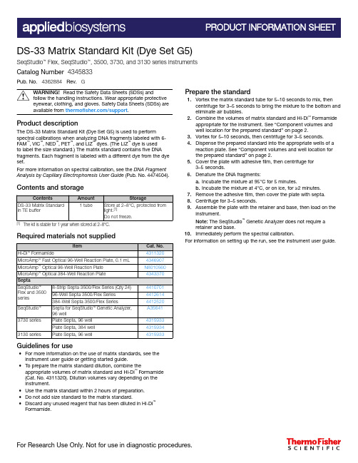
DS-33 Matrix Standard Kit (Dye Set G5) SeqStudio™ Flex, SeqStudio™, 3500, 3730, and 3130 series instruments Catalog Number 4345833Pub. No. 4362884 Rev.GWARNING! Read the Safety Data Sheets (SDSs) andfollow the handling instructions. Wear appropriate protectiveeyewear, clothing, and gloves. Safety Data Sheets (SDSs) areavailable from /support.Product descriptionThe DS-33 Matrix Standard Kit (Dye Set G5) is used to perform spectral calibrations when analyzing DNA fragments labeled with 6‐FAM™, VIC™, NED™, PET™, and LIZ™ dyes. (The LIZ™ dye is usedto label the size standard.) The matrix standard contains five DNA fragments. Each fragment is labeled with a different dye from the dye set.For more information on spectral calibration, see the DNA Fragment Analysis by Capillary Electrophoresis User Guide (Pub. No. 4474504). Contents and storage[1] The kit is stable for 1 year when stored at 2–8°C.Required materials not suppliedGuidelines for use•For more information on the use of matrix standards, see the instrument user guide or getting started guide.•To prepare the matrix standard dilution, combine the appropriate volumes of matrix standard and Hi‑Di™ Formamide (Cat. No. 4311320). Dilution volumes vary depending on theinstrument.•Use the matrix standard within 2 hours of preparation.•Do not add size standard to the matrix standard.•Discard any unused reagent that has been diluted in Hi‑Di™Formamide.Prepare the standard1.Vortex the matrix standard tube for 5–10 seconds to mix, thencentrifuge for 3–5 seconds to bring the mixture to the bottom and eliminate air bubbles.bine the volumes of matrix standard and Hi‑Di™ Formamideappropriate for the instrument. See “Component volumes andwell location for the prepared standard” on page 2.3.Vortex for 5–10 seconds, then centrifuge for 3–5 seconds.4.Dispense the prepared standard into the appropriate wells of areaction plate. See “Component volumes and well location forthe prepared standard” on page 2.5.Cover the plate with adhesive film, then centrifuge for3–5 seconds.6.Denature the DNA fragments:a.Incubate the mixture at 95°C for 5 minutes.b.Incubate the mixture at 4°C, or on ice, for ≥2 minutes.7.Remove the adhesive film, then cover the plate with septa.8.Centrifuge for 3–5 seconds.9.Assemble the plate with the retainer and base, then load on theinstrument.Note: The SeqStudio™ Genetic Analyzer does not require aretainer and base.10.Immediately perform the spectral calibration.For information on setting up the run, see the instrument user guide.For Research Use Only. Not for use in diagnostic procedures.Component volumes and well location for the prepared standardTable 1 SeqStudio ™ Flex Series Genetic AnalyzerTable 2 SeqStudio ™ Genetic AnalyzerTable 3 3500/3500xL Genetic AnalyzerTable 4 3730/3730xl DNA Analyzer[1]For 3730/3730xl Data Collection Software only when running the RCT configuration: Select dye set G5-RCT to perform fragment analysis in applications with a high dynamic range (large peaks with a signal intensity that is much higher than the signal intensity of small peaks).Table 5 3130/3130xl Genetic AnalyzerLimited product warrantyLife Technologies Corporation and/or its affiliate(s) warrant their products as set forth in the Life Technologies' General Terms and Conditions of Sale at /us/en/home/global/terms-and-conditions.html . If you have any questions, please contact Life Technologies at /support .2DS-33 Matrix Standard Kit (Dye Set G5) Product Information SheetThermo Fisher Scientific Baltics UAB | V.A. Graiciuno 8, LT-02241 | Vilnius, LithuaniaFor descriptions of symbols on product labels or product documents, go to /symbols-definition.The information in this guide is subject to change without notice.DISCLAIMER: TO THE EXTENT ALLOWED BY LAW, THERMO FISHER SCIENTIFIC INC. AND/OR ITS AFFILIATE(S) WILL NOT BE LIABLE FOR SPECIAL, INCIDENTAL, INDIRECT, PUNITIVE, MULTIPLE, OR CONSEQUENTIAL DAMAGES IN CONNECTION WITH OR ARISING FROM THIS DOCUMENT, INCLUDING YOUR USE OF IT.Revision history: Pub. No. 4362884Important Licensing Information: This product may be covered by one or more Limited Use Label Licenses. By use of this product, you accept the terms and conditions of all applicable Limited Use Label Licenses.©2022 Thermo Fisher Scientific Inc. All rights reserved. All trademarks are the property of Thermo Fisher Scientific and its subsidiaries unless otherwise specified./support | /askaquestion31 January 2022。
毕业论文-基于DSP技术为机车轴承设计故障诊断监控系统-英文翻译

原文:Design of Fault Diagnosis Monitor System for the LocomotiveBearings Based on DSP TechnologyAbstractThe rolling bearing is one of the key parts of the locomotive running components, because it condition is directly related to the performance and safety of locomotive. In this paper, the monitor system for the locomotive bearings based on DSP TMS320LF2407A is designed. This system diagnoses the rolling bearing fault using vibration analysis method. It is based on comprehensive resonance demodulation and fast Fourier transform technique, and it adopts "related methods" to handle the result of the FFT. It effectively improves the response characteristics, sensitivity, differentiate and measurement accuracy of the bearing failure monitor system, and it can fulfill the monitor and prediction of the transient fault in the course of the locomotive running.Key words: resonance demodulation technology; digital signal processor; related methodsI. IntroductionThe higher safety is required to the trains because its speed is raised constantly. Bearing fault is one of the major factors causing eventful traffic accidents and affecting rail safety. Currently the railway system usually uses the bearing temperature detector to monitor the locomotive bearing condition. Theoretical analysis and a lot of practice show that the bearing temperature detector can prevent accidents from occurring to some extent, but most of the bearing fault is not sensitive to temperature. When the temperature of the bearing is beyond the range and the system gives an alarm, the worse damage of the bearing has occurred, and even theincident had happened. Therefore, to find the fault more early and accurately, the more advanced monitoring means must be adopted. Most of the bearing fault is very sensitive to vibration signal. The fault can cause vibration of the bearing increased. Compared with monitoring the temperature of bearing, the analysis and processing results to the vibration signal has more advantage than the temperature means.II. System composing and work processBased on the need, the monitor of the bearing fault monitoring system to the locomotive bearing sets two detections: itineration detections and fixed detections. The itineration detection is used in the normal conditions, and the fixed detection is used for the continuous monitoring of the fault bearing. The system adopts special composite sensor to collect the vibration of the bearing and the temperature signal at the same time. After the data processing, the corresponding fault levels and rise in temperature are got. The data acquisition unit is designed in this system. Alarm information will be transmitted to all carriages through interfaces so that the staff can handled in time, and the same time, the fault data and the related information of the train such as the current location and speed will be transmitted to the dispatch center through GPS, which is convenient to adopt corresponding measures. The system block diagram is in Fig. 1.III. The key technology of the design for the monitoring systemA.The spectrum analysis means for diagnosing bearing faultUnder normal circumstances, all parts of the rolling bearing (inner circle, outer circle, roller, holding frame) will retain the stable relative movement state. If the surface of some element (except for holding frame) has crack, and this crack is in the surface of the rolling adjacent component, the instantaneous vibration impulse must be produced.Assumed that the number of the roller in the bearing is Z ; the diameter of the roller is d ; the average diameter of the bearing inner circle and the bearing outer circle (the diameter of the roller revolution path) is D ; the frequency of the bearing rotation is f 0. Assumed that the inner circle is fixed and the outer circle is circumvolved, the vibration frequency brought by the surface defects of different bearing components can be derived.These frequencies can be called the fault characteristics frequency of the inner circle, outer circle and the roller.()circle)(inner 2101f D d Z f +=()circle)(outer 2101f D d Z f -=()(roller)]1[021f D d d D f -=B. Resonance demodulation technologyWe can collect vibration signal using the resonance of the bearing components, and detect the envelope of the fault signal using envelop detector, which can fulfill the analysis to the fault character. This is called “resonance demodulationtechnology”. The component surfaces such as the inner circle, the outer circle and the roller of the rolling bearing are easily damaged in local place in the course of operation (such as pitting and peeling off, cracking, scratching etc.). If the surface of some bearing components have local damage and the rollingobject presses the fault dot in the course of carried operation, it must bring impact. But the impact lasts a short time, and the frequency range of the energy divergence is wide, so the energy within the scope of vibration frequency is small. Due to the wide bandwidth of the impulse, it is certainly that it includes high frequency intrinsic vibration inspiring by intrinsic frequency of the inner circle, outer circle, roller, holding frame on rolling bearings. The resonance demodulate signal is separated by band-pass filter of center frequency equal to its intrinsic frequency. Then the envelope demodulation is carried through to there attenuation oscillatory wave using software or circuit, the frequency component of the high frequency attenuation vibration is wiped off. We only obtain low-frequency envelope signal with the information of the fault character. The spectrum analysis of the envelope signal is carried through by digital signal processor, we can obtain very high frequency resolution ratio and can easily find the frequency of the corresponding fault impact, thereby we can fulfill to diagnose to the bearing fault.With resonance demodulation technology, the electric resonator which resonant frequency is much higher than normal vibration frequency and limited high-harmonic frequency is designed. Therefore, it can effectively restrain the low-frequency signal including normal vibration signal. The resonance response magnifies the signal amplitude of the impulse signal and the time of its oscillation islonger, thus the fault signal is broadened in the time domain signal. After the envelope detection and low-pass filter, the low-frequency resonance demodulation signal with high signal-to-noise ratio is exported. In the signal processing system shown in figure 2, the bearing component brings resonance under the impact, form the continuous attenuation oscillation. To research each attenuation oscillation, we can see that its frequency is the natural frequency of bearing components, the amplitude of attenuation oscillation is relate to intensity of fault impact. The amplitude of envelopesignal of the attenuation oscillation reflects the size of the fault, and the repeat frequency of the envelope depends on the fault location. System has the performance of anti-jamming of the low frequency vibration, high signal-to-noise ratio.C. Envelope detectionA bearing with fault in the course of rolling will bring regular vibration. Different fault has different character frequency. The character frequency system detecting is the frequency of the signal envelope (the frequency which is accrued by the collision of the fault on bearing element), not the vibration frequency of the bearing. When we analyze the fault signal, the resonant frequency (carrier wave) must be removed by envelope demodulation. Because the envelope signal has fully included all information of the fault, removing carrier wave will not have any adverse impact on the analysis.IV. Hardware and software designThe hardware block diagram of the monitor for the bearing fault is shown in Fig.3.The circuit includes two parts: the vibration signal pretreatments and the bearing state analysis. The signal preprocessing part fulfills the amplification, conversion, resonance demodulation of the signal; the bearing state analysis part fulfills spectrum analysis of the signal, "correlation method" processing, fault grading processing, thebearings status report and communicating with peripheral equipment and so on.There are mainly three kinds of FFT algorithm to realize in DSP: (1) only including addition and subtraction operations without operations of the plural rotation factor; (2) including the operation of the plural rotation factor; (3) the operation of bits location inversion. After data is processed by this way, the workload of vibration component calculation in DSP is reduced evidently. The real-time capacity of system response can be advanced.Modularization design is adopted in the design of the software, which includes collections of the vibration signal and the temperature increment signal, A/D conversions, data pretreatments, FFT transforms, calculations of the power spectrum, judgments of the fault grading, saves of the data, displays of the data and transmissions of the data. The task dispatch is carried through by the way of event triggers and time triggers. To remove the interference, the “correlation means” processing to the results of FFT transform is carried out, which assure the fault signal picked up effectively.V. ConclusionFFT methods of vibration signal is adopted in system design,at same time differential temperature measurement methods is added into system to judge synthetically. The high capability DSP completes signal processing. This system can commendably satisfy the requirement for real-time processing. It monitors the signal of vibrations and temperatures with combining locomotive monitor and ground analysis. The earlier diagnosis and alarm for locomotive bearings fault can be given in order to assure locomotive running safely.REFERENCES[1] Wang Dezhi,The diagnosis and maintain of rolling bearing[M],Beijing: China Railway Publishing House, 1994,[2] Shi Huafeng,Yin Guohua,etc,Fault diagnosis of locomotive bearing[J],Electric Drive For Locomotive, 2004,(2): 40~43,[3] Mei Hongbin,The libration monitoring and diagnosis of rolling bearing[M],Beijing:China Machine Press,1996,[4] Mei Hongbin,The fault diagnosis for rolling bearings using envelope analysis,Bearing,1993 ,(8):30~34,[5] Feng Gengbin,The libration diagnosis technology of the locomotive fault[M],Beijing: China Railway Publishing House,1994.[6] Jiang Simi. The hardware exploiture of TMS320LF240x DSP. Beijing: China Machine Press, 2003.[7] Qing Yuan Science and Technology. The application design of TMS320LF240XDS. Beijing: China Machine Press, 2003.译文:基于DSP技术为机车轴承设计故障诊断监控系统摘要滚动轴承是机车运行组件的关键部件之一,因为它直接关系到机车的性能和安全。
Kyle Distribution Type KFVE和KFVME(27kV)总线梁套件KRK710

Cooper Power SystemsContentsPrinted in USA1June 1996 • New IssueSafety Information .......................................................2Safety Instructions.....................................................2Hazard Statement Definitions....................................2Product Information .....................................................3Introduction................................................................3Description.. (3)Installation ....................................................................4Disassembly Procedures...........................................4Capscrew Replacement.............................................6Reassembly Procedures............................................6Testing (9)Figure 1.Type KFVE and KFVME (27kV) bus bar kit KRK710-1.961047KMType KFVE and KFVME Bus Bar Kit Installation InstructionsKFE10010-E35341210897611Disassembly ProceduresThe entire installation process should be conducted in a clean environment such as a repair shop.1.After the recloser has been de-energized, remove the recloser from service.2.With the recloser in the Open position, untank the recloser by loosening the six head bolts and washers on the head casting.Carefully lift the head assembly out of the tank using the lifting lugs (refer to Figure 3).3.Invert the head assembly (refer to Figure 4) and if aservice stand is not available, the head assembly will have to be gently set directly on the six bushing ter-minals.Note:The bushing terminals should be set on a rubber mator a piece of plywood on a level surface.Type KFVE and KFVME Bus Bar Kit Installation Instructions4INSTALLATIONControl cableA PhaseC PhaseB PhaseSleethood coverHead boltHead boltHead boltHead boltHead boltLifting lugsBushing terminalsBushing terminalsService standKFE10010-E5Nuts, lockwashers, and flatwashersHex head capscrews,lockwashers, and flatwashersBushing leadsBottom of interrupter assemblyFuse leadRound head capscrew (nuts, lockwashers and flatwashers on backside)Contactor plateFuseHex head capscrews, lockwashers,and flatwashersBushing lead support boardB.Remove and discard the bushing lead support board, the three black bushing leads, and the two fuses (refer to Figure 9).There are four button head capscrews included with this kit to replace the four hex head capscrews currently used on the interrupter mounting plate.1.One at a time replace the four hex head capscrews holding the interrupter support plate with the four but-ton head capscrews (refer to Figure 10).A.Reuse the lockwashers with the button head cap-screws.Discard the hex head capscrews and the flatwashers.B.The threads of each screw hole must be free of oil before applying Loctite to the threads of the button head capscrews.If oil is present, flush the holes with alcohol to remove all traces of oil.C.T orque (using the hex wrench included in this kit)each button head capscrew to 15 Nm (140 in.lbs.).1.In the top of the bridge plate, use the two 1-1/2 inch capscrews supplied with the kit and the two previous-ly saved lockwashers to reattach the bridge plate (refer to Figure 11).Type KFVE and KFVME Bus Bar Kit Installation Instructions6Capscrews and flatwashersFuses Bushing leadsSave the lock-washersBushing lead support boardInterrupter support plateButton head capscrewHex head capscrewsBridge plate1-1/2 in.capscrews and lockwashersKFE10010-E7Capscrews, lockwashers,and flatwashersBus barsBottom of the interrupterBushing studs, nuts, flat-washers, and lockwashersFuse and insulatorTie wireCarriage boltSlotted screw and lockwasherPredrilled holesContactor plateFuse assembly hardwareFuse leadFuse assemblyBridge plate7.Carefully place the head assembly into the tank.A.The head assembly must be adjusted to seat overthe cover gasket properly.B.The sleethood should be located 90°from the tankpole mounting bracket (refer to Figure 15).8.Tighten the six head bolts and washers on the head assembly of the tank in an alternating pattern accord-ing to the sequence shown in Figure 16.Torque each head bolt to 33-54 Nm (25-40 ft.lbs.).Type KFVE and KFVME Bus Bar Kit Installation Instructions8Pole mount-ing bracketSleethoodOne of six head bolts andwashers—torque to 33-54 Nm(25-40 ft.lbs.)Figure 16.Head bolt torque sequence.Sleethoodcover5Control cableA Phase4B Phase1C Phase36KFE10010-E。
三维感应和图像技术的模型2606B 4通道系统 SourceMeter 数据传输测试设备说明书

• Watch small orders for key customers, including startups
• 20V @ 1A and 6V @ 3A power envelopes, 20 Watts. No extended range pulsing.
• 100 nA range with 2 pA resolution
• 0.015% basic measure accuracy with 6½digit resolution
• Typically lower power applications (facial recognition)
Introducing
The Model 2606B 4-Channel System SourceMeter
4 Channels in a 1U form factor Test more devices.
Web Banners driving to product page • Center Stage • Product Carousel
Hi Resolution Photos
Tek targeted emails driving customers to product page
▪ Note: manuals and software are all on website
13
Schedule
KEY DATES & MARKETING RESOURCES
Date April 21st April 25th May 8th July 16th
Activity VIP Open Order Queue Stocking orders begin shipping Public Announcement; Sales Enablement Ready; Marketing Campaign Launch
MSL-2041CC-Vxxx_Series 062708

MSL-2041CC-VUOL MSL-2041CC-VSOL MSL-2041CC-VSO MSL-2041CC-VUYLv1.006/27/2008FeaturesPackage : White P-LCC-2 package with epoxy resinFeature of the device : High brightness in beam direction at SMT technology Wavelength : 625 nm (Red), 615 nm (Red-orange), 605 nm (Orange), 590 nm (Amber) Viewing angle : Lambertian Emitter ( 120o)Technology : AlInGaPGrouping parameter : Luminous IntensityAssembly methods : Suitable for all SMT assembly methods Soldering methods : Reflow solderingTaping : 8-mm tape with 2000 pieces / reel, φ180mm Lead free product : RoHS compliantApplicationsAutomotive : Dashboards, Stop lamps, Turn signals Backlighting : Key pads, Advertising Lighting : Signal, symbol and marker lightsDisplays : Indoor and outdoor signboards, message boards Status indicators : Industrial electronicsTechnical Data Unity Opto Technology Co., Ltd.ALLEDs洸子其科技是一家从事发光二极管产品研发、生产及销售公司,致力于为国内国际市场提供高品质,低成本的各类发光管。
E.S401 E.S404 数显扳手说明书

7Dear Customers,Thank you for purchasing our digital torque screwdriver . This manual will help you to use the many features of your new digital torque screwdriver . Before operating the torque screwdriver , please read this manual completely, and keep it nearby for future reference MAIN FEATURES• Digital torque value readout • +/- 2 % or +/-3 % accuracy •CW and CCW operation• Peak hold and track mode selectable• Buzzer and LED indicator for the 9 pre-settable target torques • Engineering units (cN-m, in-lb, kg-cm) selectable • 250 data memory for recall and joint torque auditing • Auto Sleep after about 5 minutes idle• Both AAA and rechargeable batteries are compatible • Communication functions NAMES AND FUNCTIONS OF PART S A 1. Autolock bit holder 7. Buttons 2. Communication Port 8. Torque Value 3. LCD Display 9. Units4. LED Indicator 10. Peak / Track mode5. Anti-slip handle 11. Memory number6. Battery Cover12. Clear Button1112 E.S401E.S404Accuracy *1CW ±2% CCW ±3%Data memory size 250PC Connectivity *2Yes / USB Pre-setting No.9 sets Bright LED 2 LEDs / 1 Red+1 Green Operation Mode Peak Hold / Track Unit Selection cN-m, in-lb, kg-cm Head Type Autolock bit holderButton 5Battery*3AAA x 1Operating Tempe-rature -10°C ➜ 60°C Storage Temperature-20°C ➜ 70°C Humidity Up to 90% non-condensingDrop Test 1 m Vibration Test *410 G Environmental test *5Pass Electromagnetic compatibility test *6PassSPECIFICATIONSNote:*1: The accuracy of the readout is guaranteed from 20% to 100% of maximum range + /- 1 increment. The torque accuracy is a typical value. Calibration point is on the rubber grip. For keeping the accuracy, calibrate the screwdriver for a constant period time (1 year).*2: Use a special designed USB cable (accessory) to upload record data to PC. *3: Use one AAA batteries (Test condition: Toshiba carbon-zinc R6UG battery)*4: Horizontal and vertical test *5: Environmental test: a. Dry heat e. Impact (shock) b. Cold f. Vibration c. Damp heat g. Drop d. Change of temperature *6: Electromagnetic compatibility test: a. Electrostatic discharge immunity (ESD) b. Radiated susceptibility c. Radiated emissionDigital torque screwdriverBELGIQUE Stanley Black&Decker Belgium BVBA (FACOM)LUXEMBOURG Egide Walschaertstraat 16 2800 Mechelen Belgium T +32 (0)15 47 39 30************************DANMARK FACOM NordicFINLAND Flöjelbergsgatan 1c ISLAND SE-431 35 Mölndal, Sweden NORGE Box 94, SE-431 22 Mölndal, Sweden SVERIGE Tel. +45 7020 1510 Tel. +46 (0)31 68 60 60 Tel. +47 22 90 99 10 Tel. +358 (0)10 400 4333***********************DEUTSCHLAND STANLEY BLACK & DECKER Deutschland GmbH Black & Decker Str. 40 65510 Idstein Tel.: +49 (0) 6126 21 2922 / Fax +49 (0) 6126 21 21114************************** ESPAÑA FACOM HERRAMIENTAS, S.R.L.U. C/Luis 1°, n° 60 - Nave 95 - 2ª Pta Polígono Industrial de Vallecas - 28031 MADRID Tel: +34 91 778 21 13 / Fax: +34 91 778 27 53*************************** PORTUGAL FACOM S.A.S 6/8 rue Gustave Eiffel - BP 99 91423 MORANGIS CEDEX - France Tel: 01 64 54 45 45 / Fax: 01 69 09 60 93ITALIA SWK UTENSILERIE S.R.L. Sede Operativa : Via Volta 3 21020 MONVALLE (VA) - ITALIATel: 0332 790326 / Fax: 0332 790307LATIN FACOM S.L.A.AMERICA 9786 Premier Parkway Miramar, Florida 33025 USA Tel: +1 954 624 1110 / Fax: +1 954 624 1152NETHERLANDS Stanley Black&Decker Netherlands (FACOM) POSTBUS 83 6120 AB BORN NEDERLAND Tél************/Fax****************************************ASIA The Stanleyworks( Shanghai) Co., Ltd 8/F ,Lujiazui Fund Tower No.101, Zhulin Road PuDong District Shanghai, 20122,China Tel: 8621-6162 1858 / Fax: 8621-5080 5101SUISSE Stanley Works Europe Gmbh Ringstrasse 14 CH - 8600 DÜBENDORF Tel: 00 41 44 755 60 70 / Fax: 00 41 44 755 70 67ÖSTERREICH STANLEY BLACK & DECKER Austria GmbH Oberlaaerstrasse 248A-1230 Wien Tel.: +43 (0) 1 66116-0 Fax.: +43 (0) 1 66116-613************************ www.facom.atUNITED KINGDOM Stanley Black & Decker UK Limited EIRE 3 Europa Court Sheffi eld Business Park Sheffi eld, S9 1XE Tél. +44 1142 917266 Fax +44 1142 917131 ČESKÁ REP . Stanley Black & Decker SLOVAKIA Czech Republic s.r.o.Türkova 5b 149 00 Praha 4 - Chodov Tel.: +420 261 009 780 Fax. +420 261 009 784POLSKA Stanley Black & Decker Polska Sp. z o.o ul. Postepu 21D, 02-676 Warszawa Tel: +48 22 46 42 700Fax: +48 22 46 42 701FRANCE ET FACOM S.A.SINTERNATIONALE 6/8 rue Gustave Eiffel - BP 99 91423 MORANGIS CEDEX - France Tel: 01 64 54 45 45 Fax: 01 69 09 60 93 En France, pour tous renseignements techniques sur l’outillage à main, téléphonez au : 01 64 54 45 14NU-en ES401-E.S404_0615x .k g .c m m i n i. m a x .S P E C I F I C A T I O N SI S O 6789 M o d e l 2 C l a s s D S c r e w d r i v e r p r e c i s i o n : ± 2± 3A C C E S S O R I E Se r i e s N o E S (m m ) E P (N °) E D (N °) E X (N °) E TR+E .S 404 - K I T P l u g s K I T E .S 404 - U S BU S B c a b l eS P A R E :CONNECTING COMMUNICATION CABLE• Connect the accessory cable between the USB COM port of PC and screwdriver.UPLOADING RECORD DATA• Make sure the connection between PC and screwdriver is normal.• Change the screwdriver operation mode to “SendMode Recorded Value Review ” section) • Use PC to start the uploader program.• In uploader program, first select the correct COM port No. • Next, select the fi le path to save the uploaded data.• Finally, press “upload” button to transmit the torque records to PC.• The uploaded data is then shown on the column and saved in the *.csv fi le. MAINTENANCE AND STORAGE ATTENTION:One-year periodic recalibration is necessary to maintain accuracy. accuracy.2. Do not shake violently or drop screwdriver.3. Do not use this screwdriver as a hammer.4. Do not leave this screwdriver in any place exposed to excessive heat, humidity, or direct sunlight.5. Do not use this apparatus in water.(not waterproof)6. If the screwdriver gets wet, wipe it with a dry towel as soon as possible. The salt in seawater can be especially damaging.7. Do not use organic solvents, such as alcohol or paint thinner when cleaning the screwdriver.8. Keep this screwdriver away from magnets.9. Do not expose this screwdriver to dust or sand as this could cause serious damage.10. Do not apply excessive force to the LCD panel.11. Apply torque slowly and graspe the center of the handle. Do not apply load to the end of handle.12. When checking the accuracy or calibration, please use the bit head packed inside the blow mold case.BATTERY MAINTENANCE1. When the screwdriver isnot used for an extended period of time, remove the battery.2. Keep a spare battery on hand when going on a long trip or to cold areas.3. Sweat, oil and water can prevent a battery’s terminal from makingelectrical contact. To avoid this, wipe both terminals before loading a battery.4. Dispose of batteries in a designated disposal area. Do not throw batteries into a fi re.BEFORE USING THE SCREWDRIVERBATTERY INSTALLATION B • Remove the battery cover.• Insert one AAA batterie matching the -/+ polarities of the battery to the battery compartment.• Put on the battery cap and fasten it tightly according to the following fi gures.SCREWDRIVERscrewdriver.• screwdriver before using it. ATTENTION:If an external force is applied to the torque screwdriver during power-on/reset or wake up period, an initial torque offset will exist in the memory.ACTIVATION DURING SLEEP MODE• The screwdriver again.CAUTIONS:During communication period (Send appears), the sleep function is disabled. RESETTING THE SCREWDRIVER• If the screwdriver does not function normally, loosen the cap battery and tighten it to re-start.SET UP1 . Power On/Clear2 . Unit Selection/SettingAdjust torque value 4 . Pre-Setting No.STEP 1: PRE-SETTING NO.PEAK HOLD MODE RECORDED VALUE REVIEWCOMMUNICATIONPEAK HOLD MODE OPERATION...))...))Reach 90% of Target TorqueReach Target TorqueKEY LOCKLock on/off selection。
- 1、下载文档前请自行甄别文档内容的完整性,平台不提供额外的编辑、内容补充、找答案等附加服务。
- 2、"仅部分预览"的文档,不可在线预览部分如存在完整性等问题,可反馈申请退款(可完整预览的文档不适用该条件!)。
- 3、如文档侵犯您的权益,请联系客服反馈,我们会尽快为您处理(人工客服工作时间:9:00-18:30)。
64Mb N-die SDRAM Specification54 TSOP-IIwith Lead-Free and Halogen-Free(RoHS compliant)INFORMATION IN THIS DOCUMENT IS PROVIDED IN RELATION TO SAMSUNG PRODUCTS, AND IS SUBJECT TO CHANGE WITHOUT NOTICE.NOTHING IN THIS DOCUMENT SHALL BE CONSTRUED AS GRANTING ANY LICENSE, EXPRESS OR IMPLIED, BY ESTOPPEL OR OTHERWISE,TO ANY INTELLECTUAL PROPERTY RIGHTS IN SAMSUNG PRODUCTS OR TECHNOLOGY. ALL INFORMATION IN THIS DOCUMENT IS PROVIDEDON AS "AS IS" BASIS WITHOUT GUARANTEE OR WARRANTY OF ANY KIND.1. For updates or additional information about Samsung products, contact your nearest Samsung office.2. Samsung products are not intended for use in life support, critical care, medical, safety equipment, or similar applications where Product failure couldresult in loss of life or personal or physical harm, or any military or defense application, or any governmental procurement to which special terms or provisions may apply.* Samsung Electronics reserves the right to change products or specification without notice.Table of Contents1.0 FEATURES (4)2.0 GENERAL DESCRIPTION (4)3.0 Ordering Information (4)4.0 Package Physical Dimension (5)5.0 FUNCTIONAL BLOCK DIAGRAM (6)6.0 PIN CONFIGURATION (7)7.0 Input/Output Function Description (7)8.0 ABSOLUTE MAXIMUM RATINGS (8)9.0 DC OPERATING CONDITIONS (8)10.0 CAPACITANCE (8)11.0 DC CHARACTERISTICS (9)12.0 AC OPERATING TEST CONDITIONS (11)13.0 OPERATING AC PARAMETER (11)14.0 AC CHARACTERISTICS (12)15.0 DQ BUFFER OUTPUT DRIVE CHARACTERISTICS (12)16.0 IBIS SPECIFICATION (13)17.0 SIMPLIFIED TRUTH TABLE (15)Revision HistoryRevision Month Year History1.0December2007 - Release SPEC revision 1.01.1December2007 - Revised ICC6 SPEC of lowpower1.11March2008 - Added Package pin out lead widthPart ainization Max Freq.InterfacePackageK4S640832N-LC/L758Mb x 8133MHz(CL=3)LVTTL54pin TSOP(II)Lead-Free & Halogen-FreeK4S641632N-LC/L504Mb x 16200MHz(CL=3) K4S641632N-LC/L60166MHz(CL=3) K4S641632N-LC/L75133MHz(CL=3)The K4S640832N / K4S641632N is 67,108,864 bits synchronous high data rate Dynamic RAM organized as 4 x 2,097,152 words by 8bits, / 4 x 1,048,576 words by 16 bits, fabricated with SAMSUNG ′s high performance CMOS technology. Synchronous design allows precise cycle control with the use of system clock I/O transactions are possible on every clock cycle. Range of operating frequencies,programmable burst length and programmable latencies allow the same device to be useful for a variety of high bandwidth, high perfor-mance memory system applications.• JEDEC standard 3.3V power supply• LVTTL compatible with multiplexed address • Four banks operation• MRS cycle with address key programs -. CAS latency (2 & 3)-. Burst length (1, 2, 4, 8 & Full page) -. Burst type (Sequential & Interleave)• All inputs are sampled at the positive going edge of the system clock • Burst read single-bit write operation• DQM (x8) & L(U)DQM (x16) for masking • Auto & self refresh• 64ms refresh period (4K cycle)• Lead-Free and Halogen-Free Package • RoHS compliant2M x 8Bit x 4Banks / 1M x 16Bit x 4Banks SDRAM Row & Column address configurationOrganizationRow Address Column Address8Mx8A0~A11A0-A84Mx16A0~A11A0-A71.0 FEATURES2.0 GENERAL DESCRIPTION3.0 Ordering Information4.0 Package Physical Dimension54Pin TSOP(II) Package DimensionLWE LDQMDQiSamsung Electronics reserves the right to change products or specification without notice.* 5.0 FUNCTIONAL BLOCK DIAGRAM1 2 3 4 5 6 7 8 9 10 11 12 13 14 15 16 17 18 19 20 21 22 23 24 25 26 2754535251504948474645444342414039383736353433323130292854Pin TSOP (II)(400mil x 875mil)(0.8 mm Pin pitch)Pin Name Description CLK System clock Active on the positive going edge to sample all inputs.CS Chip select Disables or enables device operation by masking or enabling all inputs except CLK, CKE and DQMCKE Clock enable Masks system clock to freeze operation from the next clock cycle. CKE should be enabled at least one cycle prior to new command. Disable input buffers for power down in standby.A0 ~ A11Address Row/column addresses are multiplexed on the same pins. Row address : RA0 ~ RA11,Column address : (x8 : CA0 ~ CA8 , x16 : CA0 ~ CA7)BA0 ~ BA1Bank select address Selects bank to be activated during row address latch time. Selects bank for read/write during column address latch time.RAS Row address strobe Latches row addresses on the positive going edge of the CLK with RAS low. Enables row access & precharge.CAS Column address strobe Latches column addresses on the positive going edge of the CLK with CAS low. Enables column access.WE Write enable Enables write operation and row precharge. Latches data in starting from CAS, WE active.DQM Data input/output mask Makes data output Hi-Z, t SHZ after the clock and masks the output. Blocks data input when DQM active.DQ0 ~ N Data input/output Data inputs/outputs are multiplexed on the same pins. (x8 : DQ0 ~ 7), (x16 : DQ0 ~ 15)V DD/V SS Power supply/ground Power and ground for the input buffers and the core logic.V DDQ/V SSQ Data output power/ground Isolated power supply and ground for the output buffers to provide improved noise immunity.N.C/RFU No connection/reserved for future useThis pin is recommended to be left No Connection on the device.x16x8x16x8V DDDQ0V DDQDQ1DQ2V SSQDQ3DQ4V DDQDQ5DQ6V SSQDQ7V DDLDQMWECASRASCSBA0BA1A10/APA0A1A2A3V DDV SSDQ15V SSQDQ14DQ13V DDQDQ12DQ11V SSQDQ10DQ9V DDQDQ8V SSN.C/RFUUDQMCLKCKEN.CA11A9A8A7A6A5A4V SSV DDDQ0V DDQN.CDQ1V SSQN.CDQ2V DDQN.CDQ3V SSQN.CV DDN.CWECASRASCSBA0BA1A10/APA0A1A2A3V DDV SSDQ7V SSQN.CDQ6V DDQN.CDQ5V SSQN.CDQ4V DDQN.CV SSN.C/RFUDQMCLKCKEN.CA11A9A8A7A6A5A4V SS6.0 PIN CONFIGURATION7.0 Input/Output Function DescriptionParameter Symbol Value Unit Voltage on any pin relative to V SS V IN , V OUT -1.0 ~ 4.6V Voltage on V DD supply relative to V SS V DD , V DDQ-1.0 ~ 4.6V Storage temperature T STG -55 ~ +150°C Power dissipation P D 1W Short circuit currentI OS50mAPermanent device damage may occur if "ASOLUTE MAXIMUM RATINGS" are exceeded.Functional operation should be restricted to recommended operating condition.Exposure to higher than recommended voltage for extended periods of time could affect device reliability.Note :Recommended operating conditions (Voltage referenced to V SS = 0V, T A = 0 to 70°C) Parameter Symbol Min Typ Max Unit NoteSupply voltage V DD , V DDQ3.0 3.3 3.6V Input logic high voltage V IH 2.0 3.0V DD +0.3V 1Input logic low voltage V IL -0.300.8V 2Output logic high voltage V OH 2.4--V I OH = -2mA Output logic low voltage V OL --0.4V I OL = 2mAInput leakage currentI LI-10-10uA31. V IH (max) = 5.6V AC.The overshoot voltage duration is ≤ 3ns.2. V IL (min) = -2.0V AC. The undershoot voltage duration is ≤ 3ns.3. Any input 0V ≤ V IN ≤ V DDQ .Input leakage currents include Hi-Z output leakage for all bi-directional buffers with Tri-State outputs.Notes : (V DD = 3.3V, T A = 23°C, f = 1MHz)PinSymbol Min Max Unit NoteClockC CLK 2.5 4.0pF RAS, CAS, WE, CS, CKE, DQM C IN 2.5 5.0pF AddressC ADD 2.5 5.0pF (x8 : DQ0 ~ DQ7), (x16 : DQ0 ~DQ15)C OUT4.06.5pF8.0 ABSOLUTE MAXIMUM RATINGS9.0 DC OPERATING CONDITIONS10.0 CAPACITANCE1. Measured with outputs open.2. Refresh period is 64ms.3. K4S640832N-LC4. K4S640832N-LL5. Unless otherwise noted, input swing IeveI is CMOS(V IH /V IL =V DDQ /V SSQ)Notes :(Recommended operating condition unless otherwise noted, T A = 0 to 70°C for x8)ParameterSymbolTest ConditionVersion UnitNote75Operating current (One bank active)I CC1 Burst length = 1 t RC ≥ t RC (min) I O = 0 mA65mA 1Precharge standby current in power-down modeI CC2P CKE ≤ V IL (max), t CC = 10ns 2mAI CC2PS CKE & CLK ≤ V IL (max), t CC = ∞2Precharge standby current in non power-down mode I CC2NCKE ≥ V IH (min), CS ≥ V IH (min), t CC = 10nsInput signals are changed one time during 20ns15mAI CC2NSCKE ≥ V IH (min), CLK ≤ V IL (max), t CC = ∞Input signals are stable 10Active standby current in power-down mode I CC3P CKE ≤ V IL (max), t CC = 10ns 4mA I CC3PS CKE & CLK ≤ V IL (max), t CC = ∞4Active standby current in non power-down mode (One bank active)I CC3NCKE ≥ V IH (min), CS ≥ V IH (min), t CC = 10nsInput signals are changed one time during 20ns30mAI CC3NSCKE ≥ V IH (min), CLK ≤ V IL (max), t CC = ∞Input signals are stable 25Operating current (Burst mode)I CC4 I O = 0 mA Page burst4Banks Activated t CCD = 2CLKs 110mA 1Refresh current I CC5t RC ≥ t RC (min)110mA 2Self refresh currentI CC6CKE ≤ 0.2VC 1mA 3L400uA411.0 DC CHARACTERISTICS (x8)1. Measured with outputs open.2. Refresh period is 64ms.3. K4S641632N-LC4. K4S641632N-LL5. Unless otherwise noted, input swing IeveI is CMOS(V IH /V IL =V DDQ /V SSQ)Notes :DC CHARACTERISTICS (x16)(Recommended operating condition unless otherwise noted, T A = 0 to 70°C for x16 only)ParameterSymbolTest ConditionVersionUnit Note506075Operating current (One bank active)I CC1 Burst length = 1 t RC ≥ t RC (min) I O = 0 mA908065mA 1Precharge standby current in power-down modeI CC2P CKE ≤ V IL (max), t CC = 10ns 2mAI CC2PS CKE & CLK ≤ V IL (max), t CC = ∞2Precharge standby current in non power-down mode I CC2N CKE ≥ V IH (min), CS ≥ V IH (min), t CC = 10nsInput signals are changed one time during 20ns 15mAI CC2NS CKE ≥ V IH (min), CLK ≤ V IL (max), t CC = ∞Input signals are stable 10Active standby current in power-down mode I CC3P CKE ≤ V IL (max), t CC = 10ns 4mAI CC3PS CKE & CLK ≤ V IL (max), t CC = ∞4Active standby current in non power-down mode (One bank active)I CC3N CKE ≥ V IH (min), CS ≥ V IH (min), t CC = 10nsInput signals are changed one time during 20ns 30mAI CC3NSCKE ≥ V IH (min), CLK ≤ V IL (max), t CC = ∞Input signals are stable 25Operating current (Burst mode)I CC4 I O = 0 mA Page burst4Banks Activated t CCD = 2CLKs 130120110mA 1Refresh current I CC5t RC ≥ t RC (min)130120110mA 2Self refresh currentI CC6CKE ≤ 0.2VC 1mA 3L400uA4(V DD = 3.3V ± 0.3V, T A = 0 to 70°C)Parameter Value Unit AC input levels (Vih/Vil)2.4/0.4V Input timing measurement reference level 1.4V Input rise and fall timetr/tf = 1/1ns Output timing measurement reference level 1.4VOutput load conditionSee Fig. 23.3V 1200Ω870ΩOutput30pFV OH (DC) = 2.4V, I OH = -2mA V OL (DC) = 0.4V, I OL = 2mAVtt = 1.4V50ΩOutput30pFZ0 = 50Ω(Fig. 2) AC output load circuit(Fig. 1) DC output load circuit Notes : 1. The minimum number of clock cycles is determined by dividing the minimum time required with clock cycle timeand then rounding off to the next higher integer.2. Minimum delay is required to complete write.3. All parts allow every cycle column address change.4. In case of row precharge interrupt, auto precharge and read burst stop.5. In 100MHz and below 100MHz operating conditions, tRDL=1CLK and tDAL=1CLK + 20ns is also supported. SAMSUNG recommends tRDL=2CLK and tDAL=2CLK + tRP .6. t RC =t RFC, t RDL = t WR .(AC operating conditions unless otherwise noted)ParameterSymbol VersionUnit Note 506075Row active to row active delay t RRD (min)101215ns 1RAS to CAS delay t RCD (min)151820ns 1Row precharge time t RP (min)151820ns 1Row active time t RAS (min)404245ns 1t RAS (max)100usRow cycle timet RC (min)556065ns 1, 6Last data in to row precharge t RDL (min)2CLK 2,5,6Last data in to Active delayt DAL (min) 2 CLK + tRP-5Last data in to new col. address delay t CDL (min)1CLK 2Last data in to burst stopt BDL (min)1CLK 2Col. address to col. address delay t CCD (min)1CLK 3Number of valid output dataCAS latency = 32ea4CAS latency = 2112.0 AC OPERATING TEST CONDITIONS13.0 OPERATING AC PARAMETER1. Parameters depend on programmed CAS latency.2. If clock rising time is longer than 1ns, (tr/2-0.5)ns should be added to the parameter.3. Assumed input rise and fall time (tr & tf) = 1ns.If tr & tf is longer than 1ns, transient time compensation should be considered, i.e., [(tr + tf)/2-1]ns should be added to the parameter.4. t SS applies for address setup time , clock enable setup time , commend setup time and data setup time t SH applies for address holde time, clock enable hold time, commend hold time and data hold timeNotes :ParameterSymbol Condition Min TypMax Unit Notes Output rise time trh Measure in linear region : 1.2V ~ 1.8V 1.37 4.37Volts/ns 3 Output fall time tfh Measure in linear region : 1.2V ~ 1.8V 1.30 3.8Volts/ns 3 Output rise time trh Measure in linear region : 1.2V ~ 1.8V 2.8 3.9 5.6Volts/ns 1,2 Output fall timetfhMeasure in linear region : 1.2V ~ 1.8V2.02.9 5.0Volts/ns1,21. Rise time specification based on 0pF + 50 Ω to V SS , use these values to design to.2. Fall time specification based on 0pF + 50 Ω to V DD , use these values to design to.3. Measured into 50pF only, use these values to characterize to.4. All measurements done with respect to V SS .Notes : (AC operating conditions unless otherwise noted)ParameterSymbol50 (x16 only) 60 (x16 only)75UnitNoteMin Max Min Max Min Max CLK cycle time CAS latency=3t CC 51000610007.51000ns 1CAS latency=2-1010CLK to valid output delay CAS latency=3t SAC - 4.5-5- 5.4ns 1,2CAS latency=2---6-6Output data hold timeCAS latency=3t OH 2- 2.5-3-ns 2CAS latency=2--3-3-CLK high pulse width t CH 2- 2.5- 2.5-ns 3CLK low pulse width t CL 2- 2.5- 2.5-ns 3Input setup time t SS 1.5- 1.5- 1.5-ns 3, 4Input hold time t SH 1-1-0.8-ns 3, 4CLK to output in Low-Z t SLZ1-1-1-ns 2CLK to output in Hi-ZCAS latency=3t SHZ- 4.5-5- 5.4nsCAS latency=2---6-614.0 AC CHARACTERISTICS15.0 DQ BUFFER OUTPUT DRIVE CHARACTERISTICSI OH Characteristics (Pull-up)Voltage 200MHz/133MHzMin200MHz/133MHzMax(V)I (mA)I (mA)3.45- -1.683.30- -19.113.00-0.35 -51.872.70-3.75-90.442.50-6.65-107.311.95-13.75-137.91.80-17.75-158.341.65-20.55-173.61.50-23.55-188.791.40-26.2-199.011.00-36.25-241.150.20-46.5-351.68I OL Characteristics (Pull-down)Voltage 200MHz/133MHzMin200MHz/133MHzMax(V)I (mA)I (mA) 3.4543.92155.82 3.30--3.0043.36153.72 1.9541.20148.40 1.8040.56146.02 1.6539.60141.75 1.5038.40136.08 1.4037.28131.39 1.0030.08105.84 0.8526.6493.66 0.6521.5275.25 0.4014.1649.14-100-200-300-400-500-600030.51 1.52 2.5 3.5VoltagemA25020015010050030.51 1.52 2.5 3.5VoltagemA200MHz/133MHz Pull-up200MHz/133MHz Pull-downI OH Min (200MHz / 133MHz)I OH Max (200MHz / 133MHz)I OL Min (200MHz / 133MHz)I OL Max (200MHz / 133MHz)16.0 IBIS SPECIFICATIONV DD Clamp @ CLK, CKE, CS, DQM & DQV DD (V)I (mA)0.00.00.20.00.40.00.60.00.70.00.80.00.90.01.0 0.231.2 1.341.4 3.021.6 5.061.8 7.352.0 9.832.212.482.415.302.618.31V SS Clamp @ CLK, CKE, CS, DQM & DQ V SS (V)I (mA)-2.6-57.23-2.4-45.77-2.2-38.26-2.0-31.22-1.8-24.58-1.6-18.37-1.4-12.56-1.2 -7.57-1.0 -3.37-0.9 -1.75-0.8 -0.58-0.7 -0.05-0.6 0.0-0.4 0.0-0.2 0.00.0 0.020151050312VoltagemAI (mA)VoltagemAI (mA)Minimum V DD clamp current(Referenced to V DD)Minimum V SS clamp current-10-20-30-40-30-2-1-50-60(V=Valid, X=Don ′t care, H=Logic high, L=Logic low)CommandCKEn-1CKEnCSRASCASWEDQMBA 0,1A 10/APA 11,A 9 ~ A 0NoteRegisterMode register set H X L L L L X OP code1,2RefreshAuto refreshH H L L L H X X 3SelfrefreshEntry L 3ExitL H L H H H X X3H X X X 3Bank active & row addr.H X L L H H X V Row address Read &column address Auto precharge disable H X L H L H X V L Column address 4Auto precharge enable H 4,5Write &column address Auto precharge disable H X L H L L X VL Column address4Auto precharge enableH 4,5Burst stop HX L H H L X X 6Precharge Bank selection H X L L H L X V L XAll banksX H Clock suspend or active power downEntry H L H X X X X XL V V V Exit L H X X X X X Precharge power down modeEntryH L H X X X XXL H H H ExitL HH X X X X L V V V DQMH X V X 7No operation commandHXH X X X XXLHHH1. OP Code : Operand codeA 0 ~ A 11 & BA 0 ~ BA 1 : Program keys. (@ MRS)2. MRS can be issued only at all banks precharge state.A new command can be issued after 2 CLK cycles of MRS.3. Auto refresh functions are as same as CBR refresh of DRAM.The automatical precharge without row precharge command is meant by "Auto". Auto/self refresh can be issued only at all banks precharge state.4. BA 0 ~ BA 1 : Bank select addresses.If both BA 0 and BA 1 are "Low" at read, write, row active and precharge, bank A is selected.If both BA 0 is "Low" and BA 1 is "High" at read, write, row active and precharge, bank B is selected. If both BA 0 is "High" and BA 1 is "Low" at read, write, row active and precharge, bank C is selected. If both BA 0 and BA 1 are "High" at read, write, row active and precharge, bank D is selected. If A 10/AP is "High" at row precharge, BA 0 and BA 1 is ignored and all banks are selected.5. During burst read or write with auto precharge, new read/write command can not be issued. Another bank read/write command can be issued after the end of burst.New row active of the associated bank can be issued at t RP after the end of burst.6. Burst stop command is valid at every burst length.7. DQM sampled at positive going edge of a CLK and masks the data-in at the very CLK (Write DQM latency is 0), but makes Hi-Z state the data-out of 2 CLK cycles after. (Read DQM latency is 2)Notes :17.0 SIMPLIFIED TRUTH TABLE。