APM9968COC-TRL中文资料
APM32F103x4x6x8xB 基于 Arm Cortex-M3 内核的 32 位微控制器 用户

用户手册APM32F103x4x6x8xB基于Arm® Cortex®-M3 内核的32位微控制器版本:V 1.1目录简介及文档描述规则 (7)简介 (7)文档描述规则 (7)系统架构 (10)术语全称、缩写描述 (10)系统架构框图 (10)存储器映射 (11)启动配置 (12)FLASH存储器 (14)术语全称、缩写描述 (14)主要特征 (14)FLASH存储器结构 (14)FLASH存储器功能说明 (15)选项字节寄存器功能描述 (17)FMC寄存器地址映射 (18)FMC寄存器功能描述 (19)复位与时钟管理(RCM) (23)术语全称、缩写描述 (23)复位功能描述 (23)时钟管理功能描述 (25)寄存器地址映射 (31)寄存器功能描述 (31)电源管理单元(PMU) (45)术语全称、缩写描述 (45)简介 (45)结构框图 (45)功能描述 (46)寄存器地址映射 (49)寄存器功能描述 (49)备份寄存器(BAKPR) (52)简介 (52)功能描述 (52)寄存器地址映射 (53)寄存器功能描述 (53)嵌套向量中断控制器(NVIC) (56)术语全称、缩写描述 (56)简介 (56)主要特征 (56)中断和异常向量表 (56)外部中断与事件控制器(EINT) (59)简介 (59)功能描述 (59)寄存器地址映射 (61)寄存器功能描述 (61)直接存储器存取(DMA) (63)术语全称、缩写描述 (63)简介 (63)主要特征 (63)功能描述 (64)寄存器地址映射 (69)寄存器功能描述 (69)调试MCU(DBGMCU) (73)术语全称、缩写描述 (73)简介 (73)主要特征 (73)功能描述 (74)寄存器地址映射 (75)寄存器功能描述 (75)通用输入/输出引脚(GPIO) (78)术语全称、缩写描述 (78)主要特征 (78)结构框图 (79)功能描述 (79)寄存器功能描述 (83)复用功能输入/输出引脚(AFIO) (86)简介 (86)功能描述 (86)寄存器地址映射 (89)寄存器功能描述 (90)定时器概述 (95)术语全称、缩写描述 (95)定时器类别及主要差异 (95)高级定时器(TMR1) (98)简介 (98)主要特征 (98)结构框图 (99)功能描述 (99)寄存器地址映射 (115)寄存器功能描述 (116)通用定时器(TMR2/3/4) (134)简介 (134)主要特征 (134)结构框图 (135)功能描述 (135)寄存器地址映射 (147)寄存器功能描述 (148)看门狗定时器(WDT) (164)简介 (164)独立看门狗定时器(IWDT) (164)窗口看门狗定时器(WWDT) (165)IWDT寄存器地址映射 (167)IWDT寄存器功能描述 (167)WWDT寄存器地址映射 (169)WWDT寄存器功能描述 (169)实时时钟(RTC) (171)术语全称、缩写描述 (171)主要特征 (171)结构框图 (171)功能描述 (171)寄存器地址映射 (172)寄存器功能描述 (173)通用同步异步收发器(USART) (177)术语全称、缩写描述 (177)简介 (177)主要特征 (177)功能描述 (178)寄存器地址映射 (190)寄存器功能描述 (191)内部集成电路接口(I2C) (198)术语全称、缩写描述 (198)简介 (198)主要特征 (198)结构框图 (199)功能描述 (200)寄存器地址映射 (206)寄存器功能描述 (206)内部集成电路接口(I2C3/4) (215)简介 (215)功能描述 (215)寄存器地址映射 (225)寄存器功能描述 (227)串行外设接口(SPI) (246)术语全称、缩写描述 (246)简介 (246)主要特征 (246)功能描述 (247)寄存器地址映射 (257)寄存器功能描述 (257)四线串行外围接口(QSPI) (263)简介 (263)主要特征 (263)功能描述 (263)寄存器地址映射 (270)寄存器功能描述 (271)控制器局域网(CAN) (281)术语全称、缩写描述 (281)简介 (281)主要特性 (281)功能描述 (281)寄存器地址映射 (289)寄存器功能描述 (290)全速USBD接口设备(USBD) (305)简介 (305)功能描述 (305)寄存器地址映射 (305)寄存器功能描述 (306)模数转换器(ADC) (315)术语全称、缩写描述 (315)简介 (316)主要特征 (316)功能描述 (317)寄存器地址映射 (326)寄存器功能描述 (326)循环冗余校验计算单元(CRC) (335)简介 (335)功能描述 (335)寄存器地址映射 (335)寄存器功能描述 (335)浮点运算单元(FPU) (337)简介 (337)功能描述 (337)寄存器地址映射 (340)寄存器功能描述 (340)芯片电子签名 (343)主存储区容量寄存器 (343)96位唯一芯片ID (343)版本历史 (345)简介及文档描述规则简介本用户手册向应用程序开发人员提供关于如何使用MCU(微控制器)系统架构、存储器和外设所涉及的全部信息。
APM4435KC-TRL中文资料
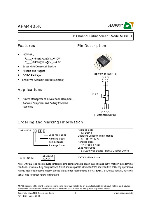
ANPEC reserves the right to make changes to improve reliability or manufacturability without notice, and advise customers to obtain the latest version of relevant information to verify before placing orders.APM4435KFeaturesApplications• Power Management in Notebook Computer,Portable Equipment and Battery Powered SystemsPin DescriptionOrdering and Marking InformationP-Channel MOSFETAPM4435Handling Code Temp. Range Package CodePackage Code K : SOP-8Operating Junction Temp. Range C : -55 to 150C Handling CodeTR : Tape & Reel Lead Free CodeL : Lead Free Device Blank : Original Device APM4435 K :XXXXX - Date CodeLead Free Code APM4435XXXXX• -30V/-8A ,RDS(ON)=16m Ω(typ.) @ VGS =-10VRDS(ON)=24m Ω(typ.) @ V GS =-4.5V• Super High Dense Cell Design • Reliable and Rugged • SOP-8 Package•Lead Free Available (RoHS Compliant)Top View of SOP − 8G(4)(1, 2, 3)(5, 6, 7, 8)Note: ANPEC lead-free products contain molding compounds/die attach materials and 100% matte in plate termina-tion finish; which are fully compliant with RoHS and compatible with both SnPb and lead-free soldiering operations.ANPEC lead-free products meet or exceed the lead-free requirements of IPC/JEDEC J STD-020C for MSL classifica-tion at lead-free peak reflow temperature.APM4435KAbsolute Maximum Ratings (TA= 25°C unless otherwise noted)Electrical Characteristics (TA = 25°C unless otherwise noted)*Surface Mounted on 1in2 pad area, t ≤ 10sec.APM4435KElectrical Characteristics (Cont.) (T= 25°C unless otherwise noted)Aa : Pulse test ; pulse width≤300µs, duty cycle≤2%.b : Guaranteed by design, not subject to production testing.APM4435K1E-41E-30.010.1110301E-30.010.112Typical Characteristics-I D - D r a i n C u r r e n t (A )Drain CurrentT j - Junction Temperature (°C)Safe Operation Area-V DS - Drain - Source Voltage (V)Thermal Transient ImpedanceSquare Wave Pulse Duration (sec)Power DissipationP t o t - P o w e r (W )T j - Junction Temperature (°C)-I D - D r a i n C u r r e n t (A )204060801001201401600.00.51.01.52.02.5204060801001201401602468100.010.11101000.010.1110100N o r m a l i z e d T r a n s i en t T h e r m a l R e s i s t a n c e012345-50-250255075100125150 -V GS - Gate - Source Voltage (V)T j - Junction Temperature (°C)APM4435K-V DS - Drain - Source Voltage (V)Drain-Source On ResistanceN o r m a l i z e dO n R e s i s t a n c e T j - Junction Temperature (°C)C - C a p a c i t a n c e (p F )-V SD - Source - Drain Voltage (V)-I S - S o u r c e C u r r e n t (A )CapacitanceGate ChargeQ G - Gate Charge (nC)-V G S - G a t e -s o u r c e V o l t a g e (V )Typical Characteristics (Cont.)-50-252550751001251500.000.250.500.751.001.251.501.752.000.1110305101520253005001000150020002500300035004000450050005101520253035404550APM4435KPackaging InformationSOP-8 pin ( Reference JEDEC Registration MS-012)APM4435KT LT P25T e m p e r a t u r eTimeReflow Condition (IR/Convection or VPR Reflow)Classification Reflow ProfilesPhysical SpecificationsAPM4435KCarrier Tape & Reel DimensionsReliability Test ProgramClassification Reflow Profiles(Cont.)APM4435KCover Tape DimensionsCarrier Tape & Reel Dimensions(Cont.)(mm)Customer ServiceAnpec Electronics Corp.Head Office :No.6, Dusing 1st Road, SBIP,Hsin-Chu, Taiwan, R.O.C.Tel : 886-3-5642000Fax : 886-3-5642050Taipei Branch :7F, No. 137, Lane 235, Pac Chiao Rd.,Hsin Tien City, Taipei Hsien, Taiwan, R. O. C.Tel : 886-2-89191368Fax : 886-2-89191369。
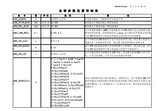
APM中文参数表for ArduCopter固件
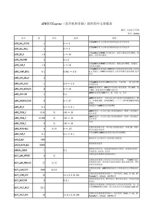
APM使用Copter(直升机和多轴)固件的中文参数表翻译:风迅电子-冷枫校对:Jothen 命令值单位选项说明ACRO_BAL_PITCH10 -- 3设置ACRO比率飞行模式时俯仰角返回水平的比率ACRO_BAL_ROLL10 -- 3设置ACRO比率飞行模式时横滚角返回水平的比率ACRO_RP_P 4.5 1 -- 10设置ACRO或者SPORT飞行模式时,俯仰与横滚动作的P值,值越高,动作相应越快ACRO_TRAINER20,1,2ACRO_YAW_P 4.5 1 -- 10设置ACRO或者SPORT飞行模式时,偏航动作的P值,值越高,动作相应越快AHRS_COMP_BETA0.10.001 -- 0.5设置AHRS航姿系统融合GPS数据计算地面速度的常数,试用值0.1,值越大,对GPS的依赖越少,会更多依赖空速传感器,值少反之AHRS_GPS_DELAY2AHRS_GPS_GAIN10.0 -- 1.0设置AHRS航姿系统对GPS的依存值,不能为0,一般飞机用默认或者1.0AHRS_GPS_MINSATS60 -- 10AHRS航姿系统中,GPS起作用的最小搜星数量,默认6颗,低于6颗,航姿系统中的GPS不起作用AHRS_GPS-USE10,1AHRS航姿系统的GPS开关,0:关闭,1;开启AHRS_ORIENTATION00 -- 37AHRS航姿系统中,飞快安装方向与标准方向的偏转矫正,0-无,1-偏航45度,2-偏航90度,…………37-横滚90度+偏航270度AHRS_RP_P0.10.1 -- 0.4加速度计对AHRS姿态控制的P值AHRS_TRIM_X0.01度-10 -- 10AHRS系统中,对飞控主板与机架的X轴向(横滚)角度偏差进行补偿AHRS_TRIM_Y-0.005度-10 -- 10AHRS系统中,对飞控主板与机架的Y轴向(俯仰)角度偏差进行补偿AHRS_TRIM_X0度-10 -- 10不用AHRS_WIND-MAX0米/秒0 -- 127设置风速的最大值,即空速与地速的速差,如果为0,则始终以空速作为参考AHRS_YAW_P0.10.1 -- 0.4罗盘或GPS对AHRS航姿系统中航向控制的P值ANGLE_MAX4500限制所有飞行模式中飞机的最大倾斜角ANGLE_RATE_MAX18000限制倾斜角速率ARMING_CHECK10,1解锁前自检开关,包括遥控接收信号检查、加速度计检查、罗盘检查。
TR8中文资料
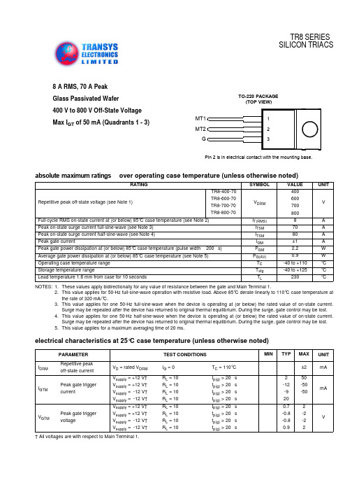
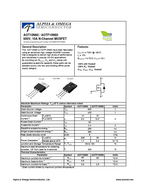
8 A RMS, 70 A Peak Glass Passivated Wafer 400 V to 800 V Off-State Voltage Max I GT of 50 mA (Quadrants 1 - 3)absolute maximum ratingsover operating case temperature (unless otherwise noted)NOTES:1.These values apply bidirectionally for any value of resistance between the gate and Main T erminal 1.2.This value applies for 50-Hz full-sine-wave operation with resistive load. Above 85°C derate linearly to 110°C case temperature atthe rate of 320 mA/°C.3.This value applies for one 50-Hz full-sine-wave when the device is operating at (or below) the rated value of on-state current.Surge may be repeated after the device has returned to original thermal equilibrium. During the surge, gate control may be lost.4.This value applies for one 50-Hz half-sine-wave when the device is operating at (or below) the rated value of on-state current.Surge may be repeated after the device has returned to original thermal equilibrium. During the surge, gate control may be lost.5.This value applies for a maximum averaging time of 20 ms.RATINGSYMBOL VALUE UNITRepetitive peak off-state voltage (see Note 1)TR8-400-70TR8-600-70TR8-700-70TR8-800-70V DRM400600700800VFull-cycle RMS on-state current at (or below) 85°C case temperature (see Note 2)I T(RMS)8A Peak on-state surge current full-sine-wave (see Note 3)I TSM 70A Peak on-state surge current half-sine-wave (see Note 4)I TSM 80A Peak gate currentI GM ±1A Peak gate power dissipation at (or below) 85°C case temperature (pulse width 200 s)P GM 2.2W Average gate power dissipation at (or below) 85°C case temperature (see Note 5)P G(AV)0.9W Operating case temperature range T C -40 to +110°C Storage temperature rangeT stg -40 to +125°C Lead temperature 1.6 mm from case for 10 secondsT L230°Celectrical characteristics at 25°C case temperature (unless otherwise noted)PARAMETERTEST CONDITIONS MINTYPMAX UNIT I DRMRepetitive peak off-state current V D = rated V DRM I G = 0T C = 110°C ±2mAI GTMPeak gate trigger currentV supply = +12 V†V supply = +12 V†V supply = -12 V†V supply = -12 V†R L = 10 R L = 10 R L = 10 R L = 10 t p(g) > 20 s t p(g) > 20 s t p(g) > 20 s t p(g) > 20 s 2-12-92050-50-50mA V GTMPeak gate trigger voltageV supply = +12 V†V supply = +12 V†V supply = -12 V†V supply = -12 V†R L = 10 R L = 10 R L = 10 R L = 10 t p(g) > 20 s t p(g) > 20 s t p(g) > 20 s t p(g) > 20 s0.7-0.8-0.80.92-2-22V† All voltages are with respect to Main Terminal 1.† All voltages are with respect to Main T erminal 1.NOTES:6.This parameter must be measured using pulse techniques, t p = 1 ms, duty cycle 2 %. Voltage-sensing contacts separate fromthe current carrying contacts are located within 3.2 mm from the device body.7.The triacs are triggered by a 15-V (open-circuit amplitude) pulse supplied by a generator with the following characteristics:R G = 100 , t p(g) = 20 s, t r = 15 ns, f = 1 kHz.V TM Peak on-state voltage I TM = ±12 A I G = 50 mA (see Note 6)±1.6±2.1V I H Holding current V supply = +12 V†V supply = -12 V†I G = 0I G = 0Init’ I TM = 100 mA Init’ I TM = -100 mA5-930-30mA I L Latching current V supply = +12 V†V supply = -12 V†(see Note 7)50-50mA dv/dt Critical rate of rise of off-state voltage V DRM = Rated V DRM I G = 0T C = 110°C ±100V/µs dv/dt (c)Critical rise of commu-tation voltageV DRM = Rated V DRMI TRM = ±12 AT C = 85°C±5V/µsthermal characteristicsPARAMETERMIN TYP MAX UNIT R JC Junction to case thermal resistance 1.8°C/W R JAJunction to free air thermal resistance62.5°C/Welectrical characteristics at 25°C case temperature (unless otherwise noted) (continued)PARAMETERTEST CONDITIONS MINTYP MAX UNITMECHANICAL DATATO-2203-pin plastic flange-mount packag eThis single-in-line package consists of a circuit mounted on a lead frame and encapsulated within a plastic compound. The compound will withstand soldering temperature with no deformation, and circuit performance characteristics will remain stable when operated in high humidity conditions. Leads require no additional cleaning or processing when used in soldered assembly.。
APM32F103RCT7 基于 Arm Cortex-M3 内核的 32 位微控制器 数据手册说明
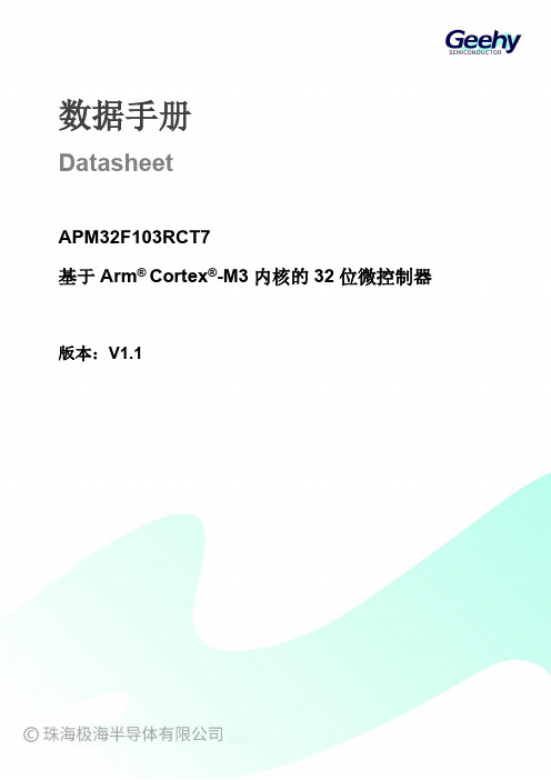
数据手册DatasheetAPM32F103RCT7基于Arm® Cortex®-M3内核的32位微控制器版本:V1.1产品特性⏹内核32位Arm®wCortex®-M3内核最高96MHz工作频率⏹片上存储器Flash:256KBSRAM:64KB⏹时钟HSECLK:支持4~16MHz外部晶体/陶瓷振荡器LSECLK:支持32.768KHzw晶体/陶瓷振荡器HSICLK:出厂校准的8MHzwRC振荡器LSICLK:支持40KHzwRC振荡器PLL:锁相环,支持2~16倍频⏹电源与电源管理V DD范围:2.0~3.6VV DDA范围:2.0~3.6V备份域电源V BAT范围:1.8V~3.6V支持上电/掉电复位(POR/PDR)支持可编程电源电压检测器⏹低功耗模式支持睡眠、停机、待机三种模式⏹DMA两个DMA,DMA1有7个通道,DMA2有5个通道⏹调试接口JTAGSWD⏹I/O有51个I/O所有I/O都可以映射到外部中断向量最多有29个容忍5V输入的I/O⏹通信外设2个I2C接口(1Mbit/s),全部支持SMBus/PMBus3个USART,2个UART,支持ISO7816、LIN和IrDA等功能3个SPI(18Mbps)接口,其中两个支持I2S接口复用2个CAN,支持USBD和CAN可同时独立工作1个USBD⏹模拟外设3个12位的ADC,最多支持16个外部通道2个12位的DAC⏹定时器2个可以提供7通道PWM输出的16位高级定时器TMR1/8,支持死区生成和刹车输入等功能4个16位通用定时器TMR2/3/4/5,每个定时器有4个独立通道可以用来输入捕获、输出比较、PWM与脉冲计数等功能2个16位基本定时器TMR6/72个看门狗定时器:一个独立看门狗IWDT和一个窗口看门狗WWDT1个24位自减型系统定时器SyswTickwTimer⏹RTC支持日历、闹钟功能⏹84Bytes备份寄存器⏹CRC计算单元⏹96位唯一设备ID目录产品特性 (1)产品信息 (4)引脚信息 (5)引脚分布 (5)引脚功能描述 (5)功能描述 (11)系统架构 (11)内核 (13)中断控制器 (13)片上存储器 (13)时钟 (13)电源与电源管理 (15)低功耗模式 (15)DMA (16)GPIO (16)通信外设 (16)模拟外设 (18)定时器 (18)RTC (19)CRC (20)电气特性 (21)电气特性测试条件 (21)通用工作条件下的测试 (23)绝对最大额定值 (24)片上存储器 (25)时钟 (25)电源与电源管理 (27)功耗 (28)低功耗模式唤醒时间 (35)引脚特性 (35)通信外设 (37)模拟外设 (40)封装信息 (43)LQFP64封装图 (43)包装信息 (45)带状包装 (45)托盘包装 (46)订货信息 (48)常用功能模块命名 (49)版本历史 (50)APM32F103RCT7产品功能和外设配置请参阅下表。
APM32F072x8xB 32位微控制器数据手册说明书

数据手册DatasheetAPM32F072x8xB基于Arm® Cortex®-M0+内核的32位微控制器版本:V1.5产品特性⏹内核32位Arm®w Cortex®-M0+内核最高48MHz工作频率⏹片上存储器Flash:64~128KBSRAM:16KB⏹时钟4~32MHz晶体振荡器带校准的32.768KHzw晶体/陶瓷振荡器内部8MHzwRC振荡器内部48MHz自动校正RC振荡器内部40KHzwRC振荡器PLL支持2~16倍频⏹复位、电源管理上电/掉电复位(POR/PDR)可编程电压调节器数字供电电压:V DD=2.0~3.6V模拟供电电压:V DDA=V DD~3.6V部分I/O供电电压:V DDIO2=1.65~3.6V支持外部电池V BAT为RTC供电:V BAT=1.65~3.6V⏹低功耗模式睡眠、停机、待机模式⏹串行线调试(SWD)⏹I/O最多87个I/Os所有I/O可映射到外部中断向量最多68个容忍5V输入的I/O,19个I/O由V DDIO2供电⏹通信接口2个I2C接口(1Mbit/s),全部支持SMBus/PMBus和唤醒。
4个USART接口,全部支持主同步SPI和调制解调控制,其中2个支持ISO7816、LIN、IrDA接口、自动波特率检测和唤醒。
2个SPI接口(18Mbit/s),全部支持I2S接口复用1个CAN接口1个全速USBD2.0接口,无需外挂晶振,支持BCD和LPMHDMIwCEC⏹模拟外设1个12位ADC,最多支持16个外部通道,转换范围0~3.6V,独立模拟电源输入:2.4~3.6V1个双通道、12位DAC2个可编程模拟比较器最多24个电容传感通道,可用于接近、触键、线性或旋转传感器⏹定时器1个可提供最多7通道PWM输出的16位的高级控制定时器,支持死区生成和刹车输入功能1个32位和5个16位通用定时器,每个定时器最多有4个独立通道用于输入捕获/输出比较。
APM全部参数表
ARSPD_RATIO ARSPD_SKIP_CAL
1.9936 0
ARSPD_TUBE_ORDE R
2
ARSPD_USE
0
AUTO_FBW_STEER
0
0:禁用 1:启用
AUTOTUNE_LEVEL BATT_AMP_OFFSET BATT_AMP_PERVOL T BATT_CAPACITY BATT_CURR_PIN BATT_MONITOR BATT_VOLT_MULT
603362704.doc
第 4 页 共 35 页
ARSPD_PIN
0
空速计连接到的模拟 IO 口. 设置这个参数为 0-9 来对应 APM2 的模拟 引脚. 使用 APM1 时设置为 64,对应于板子末端的空速计接口. 使用 PX4 时设为 11,对应于模拟空速计接口. 使用 Pixhawk 时设为 15, 对应于模拟空速计接口. 使用 EagleTree 或 MEAS I2C 空速计的 PX4 或者 Pixhawk,设置为 65. 空速计校准后的比率 这个参数允许你在皮托管里的连接顺序有影响时选择. 如果设置为 0 则顶部连接的传感器是动态压强. 如果设置为 1 则底部连接的传感 器是动态压强. 若设为 2(默认)则空速管驱动器将会接受任意一种 顺序.你可能想要指定顺序的原因在于它能够使你的空速计检测飞行 器是不是受到了过大的静压强,而这可能被解读成正空速. 1:使用 0:不使用 使用空速数据进行飞行控制 开启此项将使得在自动模式中可以使用 FBWA 的方式进行操控. 这可 以用来执行带有航点逻辑的人工增稳飞行,或可用于载荷[译注:即 飞的时候知道航点,一个个航点飞过去]. 启用后飞行员拥有和 FBWA 模式中一样的操控, 但普通的自动模式导航被完全禁用. 寻常情况 不推荐这个选项. 自动调参的激烈程度. 在较低等级的 AUTOTUNE_LEVEL 上自动调参较 为柔和, 增益较小. 对于大多数用户而言推荐 5 级. 在 0 电流情况下传感器的电压读数偏移值 当电流传感器读数为 1V 时转换得到的电流值. 对于使用 3DR 电源模 块的 APM2 或者 Pixhwak 这个值必须为 17. 对于使用 3DR 四合一电调 的 Pixhawk 这个值必须为 17. 满电电池的容量,以 mAh 计 -1:禁 用 1:A1 12:A12 2:A2 3:Pixhawk 101:PX4 设置这个参数为 0 至 13 将指定电池电流传感器的管脚对应于 A0 至 A13. 对于 APM2.5 的电源模块,这个值必须为 12. 在 PX4 上这个值 必须为 101. 对于使用电源模块的 Pixhawk 这个值必须为 3. 控制电池电流或电压监控 用来将电压传感器管脚检测到的电压值(BATT_VOLT_PIN)转换成实际 电压值(管脚电压*VOLT_MULT). 对于 APM2 或者 Pixhawk 的 3DR 电源
Moxa UC-8100A-ME-T 系列 Arm Cortex-A8 1GHz IIoT 閘道器

UC-8100A-ME-T系列Arm Cortex-A81GHz IIoT閘道器,內建LTE Cat.操作溫度為-40至70°C特色與優點•Armv7Cortex-A81000Mhz處理器•Moxa工業Linux,提供10年長期支援•兩個自動感應10/100Mbps乙太網路連接埠•用於儲存裝置擴充的SD卡插槽•配備可程控LED以及可程控按鈕,讓您輕鬆地完成安裝與維護•適用無線模組的Mini-PCIe插槽•LTE規格電腦,獲得Verizon/AT&T認證以及工業級CE/FCC/UL認證•-40到70°C寬溫度範圍,已啟用LTE認證簡介UC-8100A-ME-T運算平台專為內嵌式資料擷取應用所設計。
電腦配備雙RS-232/422/485串列埠和雙10/100Mbps乙太網路連接埠,以及Mini PCIe插槽以支援行動通訊模組。
這些多元功能讓使用者能有效地調整UC-8100A-ME-T以適應各種複雜通訊解決方案。
UC-8100A-ME-T採用的是專為能源監視系統進行最佳化的Cortex-A8處理器,但是該處理器目前已被廣泛地用於各種工業解決方案。
這款輕薄的嵌入式電腦是可靠且安全的閘道,具備彈性的介面選項,可協助您在現場進行資料擷取並進行處理,同時也是適用於許多其他大規模部署的實用通訊平台。
備有已啟用LTE的寬溫度型號供您選擇。
所有裝置全都在試驗室中經過完整測試,保證已啟用LTE的運算平台適用於寬溫應用。
外觀規格ComputerCPU Armv7Cortex-A81GHzPre-installed OS Moxa Industrial Linux(Debian9,Kernel4.4)See /MILDRAM1GB DDR3Storage Pre-installed8GB eMMCStorage Slot SD slots x1Computer InterfaceTPM TPM v2.0USB2.0USB2.0hosts x1,type-A connectorsConsole Port RS-232(TxD,RxD,GND),4-pin header output(115200,n,8,1) Expansion Slots UC-8112A-ME-T-LX:mPCIe slot x1Number of SIMs1SIM Format MiniButtons Reset buttonSerial Ports RS-232/422/485ports x2,software-selectable(terminal block) Cellular Antenna Connector SMA x2GPS Antenna Connector SMA x1Ethernet InterfaceEthernet Ports Auto-sensing10/100Mbps ports(RJ45connector)x2 Magnetic Isolation Protection 1.5kV(built-in)Serial InterfaceBaudrate300bps to921.6kbpsData Bits5,6,7,8Parity None,Even,Odd,Space,MarkStop Bits1,1.5,2Serial SignalsRS-232TxD,RxD,RTS,CTS,GNDRS-422Tx+,Tx-,Rx+,Rx-,GNDRS-485-2w Data+,Data-,GNDRS-485-4w Tx+,Tx-,Rx+,Rx-,GNDCellular InterfaceBand Options US model:LTE Bands:Band2(1900MHz)/Band4(1700MHz)/Band5(850MHz)/Band13(700MHz)/Band17(700MHz)UMTS Bands:Band2(1900MHz)/Band5(850MHz)Carrier Approval:Verizon,AT&TEU model:LTE Bands:Band1(2100MHz)/Band3(1800MHz)/Band5(850MHz)/Band7(2600MHz)/Band8(900MHz)/LTE Band20(800MHz)UMTS Bands:Band1(2100MHz)/Band2(1900MHz)/Band5(850MHz)/Band8(900MHz)AP model:LTE Bands:Band1(2100MHz)/Band3(1800MHz)/Band5(850MHz)/Band7(2600MHz)/Band8(900MHz)/Band28(700MHz)UMTS Bands:Band1(2100MHz)/Band2(1900MHz)/Band5(850MHz)/Band8(900MHz)GPS InterfaceReceiver Types72-channel u-blox M8engineGPS/GLONASS/GalileoAccuracy Position:2.5m CEPSBAS:2.0m CEPAcquisition Aided starts:3secCold starts:26secSensitivity Cold starts:-148dBmTracking:-164dBmTime Pulse0.25Hz to10MHzLED IndicatorsSystem Power x1Programmable x1SD slots x1USB x1,Diagnostic x3Wireless Signal Strength Cellular/Wi-Fi x3Power ParametersInput Current UC-8112A-ME-T-LX:500mA@12VDCAll other models:700mA@12VDCInput Voltage12to36VDCPower Consumption UC-8112A-ME-T-LX:6WAll other models:8WReliabilityAlert Tools External RTC(real-time clock)Automatic Reboot Trigger External WDT(watchdog timer)Physical CharacteristicsDimensions141x125.6x33mm(5.55x4.94x1.3in)Housing MetalInstallation DIN-rail mountingWall mounting(with optional kit)Weight550g(1.22lb)Environmental LimitsAmbient Relative Humidity5to95%(non-condensing)Operating Temperature UC-8112A-ME-T-LX:-40to85°C(-40to185°F)UC-8112A-ME-T-LX-AP:-40to70°C(-40to158°F)UC-8112A-ME-T-LX-US:-40to70°C(-40to158°F)UC-8112A-ME-T-LX-EU:-40to70°C(-40to158°F)Storage Temperature(package included)-40to85°C(-40to185°F)Shock IEC60068-2-27Vibration2Grms@IEC60068-2-64,random wave,5-500Hz,1hr per axis(without USB devicesattached)Standards and CertificationsEMC EN55032/35EMI CISPR32,FCC Part15B Class AEMS IEC61000-4-2ESD:Contact:4kV;Air:8kVIEC61000-4-3RS:80MHz to5GHz:3V/mIEC61000-4-4EFT:Power:1kV;Signal:0.5kVIEC61000-4-6CS:3VIEC61000-4-5Surge:Power:0.5kV;Signal:1kVIEC61000-4-8PFMFSafety UL62368-1,EN62368-1Hazardous Locations Class I Division2ATEXIECExCarrier Approvals AT&TVerizonGreen Product RoHS,CRoHS,WEEEMTBFTime UC-8112A-ME-T-LX:868,326hrsUC-8112A-ME-T-LX-US:677,570hrsUC-8112A-ME-T-LX-EU:677,570hrsUC-8112A-ME-T-LX-AP:677,570hrsStandards Telcordia(Bellcore)Standard TR/SRWarrantyWarranty Period5yearsDetails See /tw/warrantyPackage ContentsDevice1x UC-8100A-ME-T Series computerCable1x console cableDocumentation1x quick installation guide1x warranty cardInstallation Kit1x DIN-rail kit(preinstalled)1x power jack尺寸訂購資訊Model Name CPU RAM Storage LTE Operating Temp. UC-8112A-ME-T-LX1GHz1GB8GB–-40to85°CUC-8112A-ME-T-LX-US1GHz1GB8GB US Region-40to70°CUC-8112A-ME-T-LX-EU1GHz1GB8GB EU Region-40to70°CUC-8112A-ME-T-LX-AP1GHz1GB8GB APAC Region-40to70°C配件(選購)Power AdaptersPWR-12150-AU-SA-T Locking barrel plug,12VDC,1.5A,100to240VAC,Australia(AU)plug,-40to75°C operatingtemperaturePWR-12150-UK-SA-T Locking barrel plug,12VDC,1.5A,100to240VAC,United Kingdom(UK)plug,-40to75°C operatingtemperaturePWR-12150-CN-SA-T Locking barrel plug,12VDC,1.5A,100to240VAC,China(CN)plug,-40to75°C operating temperature PWR-12150-EU-SA-T Locking barrel plug,12VDC,1.5A,100to240VAC,Continental Europe(EU)plug,-40to75°C operatingtemperaturePWR-12150-USJP-SA-T Locking barrel plug,12VDC1.5A,100to240VAC,United States/Japan(US/JP)plug,-40to75°Coperating temperatureCablesCBL-F9DPF1x4-BK-100Console cable with4-pin connector,1mAntennasANT-LTE-OSM-03-3m BK700-2700MHz,multi-band antenna,specifically designed for2G,3G,and4G applications,3m cable ANT-LTE-OSM-06-3m BK MIMO Multiband antenna with screw-fastened mounting option for700-2700/2400-2500/5150-5850MHzfrequenciesANT-LTE-ASM-05BK704-960/1710-2620MHz,LTE stick antenna,5dBiANT-LTE-ASM-04BK704-960/1710-2620MHz,LTE omni-directional stick antenna,4.5dBiANT-LTEUS-ASM-01GSM/GPRS/EDGE/UMTS/HSPA/LTE,omni-directional rubber duck antenna,1dBiDIN-Rail Mounting KitsUC-8100A-ME DIN-Rail Kit DIN-rail mounting kit for UC-8100A-ME-T SeriesWall-Mounting KitsUC-8100A-ME Wall Mount Kit Wall-mounting kit for UC-8100A-ME-T Series©Moxa Inc.版權所有.2021年12月17日更新。
APM9926AKC-TRL中文资料

ANPEC reserves the right to make changes to improve reliability or manufacturability without notice, and advise customers to obtain the latest version of relevant information to verify before placing orders.APM9926AKFeaturesApplicationsPin DescriptionOrdering and Marking InformationN-Channel MOSFETAPM9926AHandling Code Temp. Range Package CodePackage Code K : SOP-8Operating Junction Temp. Range C : -55 to 150°C Handling CodeTU : Tube TR : Tape & Reel Lead Free CodeL : Lead Free Device Blank : Original Device APM9926A K :APM9926A XXXXXXXXXX - Date CodeLead Free Code • 20V/6A,R DS(ON) =28m Ω(typ.) @ V GS =4.5V R DS(ON) =34m Ω(typ.) @ V GS =2.5V• Super High Dense Cell Design • Reliable and Rugged• Lead Free Available (RoHS Compliant)• Power Management in Notebook Computer,Portable Equipment and Battery Powered SystemsG1S1S2G2D1D1D2D2Top View of SOP − 8(5)(6)(3)(8)(7)(2)(1)Note: ANPEC lead-free products contain molding compounds/die attach materials and 100% matte in plate termina-tion finish; which are fully compliant with RoHS and compatible with both SnPb and lead-free soldiering operations.ANPEC lead-free products meet or exceed the lead-free requirements of IPC/JEDEC J STD-020C for MSL classifica-tion at lead-free peak reflow temperature.APM9926AKAbsolute Maximum Ratings (T A = 25°C unless otherwise noted)*Surface Mounted on 1in2 pad area, t ≤ 10sec.Electrical Characteristics (T A = 25°C unless otherwise noted)APM9926AKElectrical Characteristics (Cont.) (T A = 25°C unless otherwise noted)a : Pulse test ; pulse width≤300µs, duty cycle≤2%.b : Guaranteed by design, not subject to production testing.APM9926AK1E-41E-30.010.1110301E-30.010.112Typical CharacteristicsI D - D r a i n C u r r e n t (A )Drain CurrentT j - Junction Temperature (°C)Safe Operation AreaV DS - Drain - Source Voltage (V)Thermal Transient ImpedanceSquare Wave Pulse Duration (sec)Power DissipationP t o t - P o w e r (W )T j - Junction T emperature (°C)I D - D r a i n C u r r e n t (A )204060801001201401600.00.51.01.52.02.520406080100120140160012345670.010.11101000.010.111050N o r m a l i z e d T r a n s i en t T h e r m a l R e s i s t a n c eAPM9926AKR D S (O N ) - O n - R e s i s t a n c e (m Ω)Drain-Source On ResistanceI D - Drain Current (A)T j - Junction T emperature (°C)Gate Threshold Voltage V DS - Drain-Source Voltage (V)I D - D r a i n C u r r e n t (A )Output CharacteristicsV GS - Gate - Source Voltage (V)I D - D r a i n C u r r e n t (A )N o rm a l i z e d T h r e s h o l d V o l t a g eTypical Characteristics (Cont.)1234502468101214161820481216200.00.10.20.30.40.50.60.70.80481216200.20.40.60.81.01.21.41.6APM9926AKV DS - Drain - Source Voltage (V)Drain-Source On ResistanceN o r m a l i z e d O n R e s i s t a n c eT j - Junction T emperature (°C)C - C a p a c i t a n c e (p F )I S - S o u r c e C u r r e n t (A )CapacitanceQ G - Gate Charge (nC)V G S - G a t e - s o u r c e V o l t a g e (V )Typical Characteristics (Cont.)11020048121620100200300400500600700800-50-252550751001251500.00.40.81.21.62.02.448121620012345678910APM9926AKPackaging InformationSOP-8 pin ( Reference JEDEC Registration MS-012)APM9926AKT LT P25T e m p e r a t u r eTim eReflow Condition (IR/Convection or VPR Reflow)Classification Reflow ProfilesPhysical SpecificationsAPM9926AKClassification Reflow Profiles(Cont.)Reliability Test ProgramCarrier Tape & Reel DimensionsAPM9926AKCustomer ServiceAnpec Electronics Corp.Head Office :5F, No. 2 Li-Hsin Road, SBIP,Hsin-Chu, T aiwan, R.O.C.T el : 886-3-5642000Fax : 886-3-5642050Taipei Branch :7F, No. 137, Lane 235, Pac Chiao Rd.,Hsin Tien City, Taipei Hsien, T aiwan, R. O. C.T el : 886-2-89191368Fax : 886-2-89191369Cover Tape DimensionsCarrier Tape & Reel Dimensions(Cont.)(mm)。
拉雷尔电子有限公司88-PRO循环powered进程表说明书

LAURELELECTRONICS, INC.88-PRO Loop Powered Process Meter With 0.50" high LCD digits and detachable screw terminalsFeatures• Powered by 4-20 mA, 10-50 mA or 1-5 mA loop, with no need for other power • Maximum 2.5 V voltage drop• Easy zero & span adjustment from rear of meter • 3-1/2 digit resolution (±1999)• Jumper-selectable dummy right-hand zeros for reading to ±19990 or ±199900 • Normal or inverted scaling• High-legibility 12.7 mm (0.50") digits• 1/8 DIN panel cutout, only 93 mm (3.66") required behind panel • Environmental protection to IP54 (NEMA-12) when panel mounted • High-quality plug-in screw terminals •Low costDescriptionLoop powered. The 88-PRO Process Meter may be connected directly to a 4-20 mA, 10-50 mA or 1-5 mA current loop, with no need for additional power to the meter. This is because the meter is powered directly by the current loop, developing a maximum voltage drop of 2.5 V.Readout in engineering units. By accepting 4-20 mA, 10-50 mA or 1-5 mA signals, the 88-PRO is compatible with a large number of industrial transducers and transmitters to display process variables such as temperature, pressure, flow, weight, pH,humidity etc. Zero and span are adjustable for direct readout in engineering units. There is an INVERT facility, so that anincreasing input signal gives a reducing display, for example, 4-20 mA = 100.0 to 0.0. The 88-PRO also provides two jumper-selectable dummy right-hand zero to extend the maximum reading from the default of ±1999 to ±19990 or ±199900. This feature allows the display of large numbers, such as the weight of a truck in pounds. It also useful when the cost of a 4 ½ or 5 ½ digit meter may be too highEasy to install and set up. The 88-PRO fits in a standard 1/8 DIN panel cutout and only requires 93 mm (3.66") behind the panel. This is less than for most process meters. There are only two signal connections: signal in and signal out. These are made via a detachable screw terminal connector. All range-selection jumpers as well as the meter's zero and span adjustments are from the rear of the meter, avoiding the need to open the case.Attractive and easy to read. The facia of the 88-PRO isattractively styled. The simple bezel will compliment your panel design. The lens protects all legends and markings, so repeated wipe-downs won't damage the lettering or display clarity. High contrast LCDs make these meters suitable for use in bright environments. The digits measure a full 12.7 mm (0.50").An application example. The 88-PRO loop-powered process meter is in series with 12-30 Vdc power to a two-wire 4-20 mA pressure transmitter, which measures the pressure at the bottom of a straight-sided tank. The meter's broad scaling capabilities allow it to be adjusted to display the volume of the tank. When necessary, one or two dummy right hand zeros may be added to display values up to 199900.MechanicalPanel cutout: 45 mm high x 92 mm wide (1/8 DIN)SpecificationsSignalRangeEffective resistance Maximum voltage drop 4-20 mA125 Ω2.5 V10-50 mA50 Ω2.5 V1-5 mA500 Ω2.5 VDisplayDisplay rangeDisplay heightDisplay typeDecimal point selection Display update rate Open circuit response Decimal point selection ±1999, ±19990, ±199900 (jumper-selectable) 12.7 mm (0.50")High-contrast LCDPush-on jumpers3 / secDisplay blanksPush-on jumpers behind front panelElectricalAccuracy Resolution, max. Calibration method CMRRLinear rangesA-D conversion Integration period Power ± 0.1% of reading ± 1 count1 part in 2000Zero & span potentiometers65 dB, 0-450 Hz3-21 mA, 8-52 mA, 0.8-6 mADual slope integration100 msDerived from current loop with 2.5 V max dropMechanicalBezel dimensions Panel cutoutDepth behind panel Width behind panel Case material WeightElectrical connections 48 x 96 mm (1.89" x 3.78"), H x W 45 x 92 mm (1.77" x 3.62"), H x W 93 mm (3.66") including connector 98 mm (3.86") max. Polycarbonate, UL rating 94V-0100 g (3.5 oz)Detachable screw terminal connectorEnvironmentalOperating temperature Humidity -10°C to 50°C (14°F to 122°F)-20° RH at 50°C (122°F), non-condensingOrdering GuideCreate a model a model number in this format: 88-PRO, BOX1DPM Type88-PRO 88-PRO Loop Powered Process Meter.Add-on Options IPC Clear front panel cover sealed to NEMA 4X / IP65BOX1NEMA-4X wall-mount enclosure with 1/8 DIN cutoutBOX2BOX1 plus IPC。
AOT9608中文资料
Continuous DrainParameter T =25°C Gate-Source Voltage Drain-Source Voltage Absolute Maximum Ratings T =25°C unless otherwise notedAOT10N60 / AOTF10N60DSDSSymbolMin Typ Max Units600V 700V BV DSS /∆T J 0.65V/ oC 110I GSS ±100nA V GS(th)345V R DS(ON)0.60.75Ωg FS 15S V SD 0.731V I S 10A I SM36A C iss 110013201600pF C oss 105130160pF C rss 7.59.311pF R g33.86ΩQ g 31.140nC Q gs 6.410nC Q gd 14.420nC t D(on)2835ns t r 6680ns t D(off)7695ns t f 6480ns t rr 290350ns Q rr3.94.7µC4.4THIS PRODUCT HAS BEEN DESIGNED AND QUALIFIED FOR THE CONSUMER MARKET. APPLICATIONS OR USES AS CRITICAL COMPONENTS IN LIFE SUPPORT DEVICES OR SYSTEMS ARE NOT AUTHORIZED. AOS DOES NOT ASSUME ANY LIABILITY ARISING OUT OF SUCH APPLICATIONS OR USES OF ITS PRODUCTS. AOS RESERVES THE RIGHT TO IMPROVE PRODUCT DESIGN,FUNCTIONS AND RELIABILITY WITHOUT NOTICE.V DS =480V, T J =125°C Breakdown Voltage Temperature CoefficientI D =250µA, V GS =0V Gate Threshold VoltageV DS =V GS , I D =250µA V DS =600V, V GS =0V V DS =0V, V GS =±30V Zero Gate Voltage Drain Current Gate-Body leakage current Body Diode Reverse Recovery TimeI D =250µA, V GS =0V, T J =25°C V GS =10V, I D =5A Reverse Transfer Capacitance I F =10A,dI/dt=100A/µs,V DS =100VV GS =0V, V DS =25V, f=1MHz SWITCHING PARAMETERS I DSS µA Maximum Body-Diode Pulsed CurrentElectrical Characteristics (T J =25°C unless otherwise noted)STATIC PARAMETERS Parameter Conditions Static Drain-Source On-Resistance Forward TransconductanceDiode Forward Voltage I S =1A, V GS =0V V DS =40V, I D =5ATurn-On Rise Time Turn-Off DelayTime V GS =10V, V DS =300V, I D =10A, R G =25ΩGate resistanceV GS =0V, V DS =0V, f=1MHzTurn-Off Fall TimeTotal Gate Charge V GS =10V, V DS =480V, I D =10AGate Source Charge Gate Drain Charge BV DSS Drain-Source Breakdown Voltage I D =250µA, V GS =0V, T J =150°C Body Diode Reverse Recovery Charge I F =10A,dI/dt=100A/µs,V DS =100VMaximum Body-Diode Continuous Current Input Capacitance Output Capacitance Turn-On DelayTime DYNAMIC PARAMETERS A: The value of R θJA is measured with the device in a still air environment with T A =25°C.B. The power dissipation P D is based on T J(MAX)=150°C, using junction-to-case thermal resistance, and is more useful in setting the upper dissipation limit for cases where additional heatsinking is used.C: Repetitive rating, pulse width limited by junction temperature T J(MAX)=150°C.D. The R θJA is the sum of the thermal impedence from junction to case R θJC and case to ambient.E. The static characteristics in Figures 1 to 6 are obtained using <300 µs pulses, duty cycle 0.5% max.F. These curves are based on the junction-to-case thermal impedence which is measured with the device mounted to a large heatsink, assuming a maximum junction temperature of T J(MAX)=150°C.G. L=60mH, I AS =4.4A, V DD =50V, R G =25Ω, Starting T J =25°CRev 0. July 2008VdsC ha rgeG ate Charge Test Circuit & W av eformResistiv e Switching Test Circuit & W av eformsVddVdsI dVgsB V I Unclamped Inductive Switching (UIS) Test Circuit & W av eformsARDSS2E = 1/2 LI VddARAR。
APM3095PUC-TR中文资料

ANPEC reserves the right to make changes to improve reliability or manufacturability without notice, and advise customers to obtain the latest version of relevant information to verify before placing orders.APM3095PUAPM3095PHandling Code Temp. Range Package CodePackage Code U : TO-252Operating Junction Temp. RangeC : -55 to 150 CHandling CodeTU : Tube TR : Tape & Reel Lead Free CodeL : Lead Free Device Blank : Original Device APM3095P U :APM3095P XXXXXXXXXX - Date CodeLead Free Code Pin DescriptionOrdering and Marking InformationFeaturesApplications• -30V/-8A,R DS(ON)=95m Ω (typ.) @ V GS =-10V R DS(ON)=140m Ω (typ.) @ V GS =-4.5V• Super High Dense Cell Design • Reliable and Rugged• Lead Free Available (RoHS Compliant)• Power Management in Desktop Computer orDC/DC ConvertersTop View of TO-252P-Channel MOSFETGDSGNote: ANPEC lead-free products contain molding compounds and 100% matte tin plate termination finish;which are fully compliant with RoHS and compatible with both SnPb and lead-free soldiering operations.ANPEC lead-free products meet or exceed the lead-free requirements of IPC/JEDEC J STD-020C for MSL classification at lead-free peak reflow temperature.°APM3095PUAbsolute Maximum RatingsAPM3095PUElectrical Characteristics (T= 25°C unless otherwise noted)Aa : Pulse test ; pulse width≤300µs, duty cycle≤2%.b : Guaranteed by design, not subject to production testing.APM3095PU1E-41E-30.010.11101000.010.112Typical CharacteristicsPower Dissipation P t o t - P o w e r (W )T j - Junction Temperature (°C)-I D - D r a i n C u r r e n t (A )Drain CurrentT j - Junction T emperature (°C)Safe Operation Area-V DS - Drain - Source Voltage (V)-I D - D r a i n C u r r e n t (A )N o r m a l i z e d T r a n s i en t T h e r m a l R e s i s t a n c e Thermal Transient ImpedanceSquare Wave Pulse Duration (sec)204060801001201401601800102030405060204060801001201401601802468100.11101000.010.1110100-V DS - Drain - Source Voltage (V)-I D - Drain Current (A)Transfer Characteristics -V GS - Gate - Source Voltage (V)-I D - D r a i n C u r r e n t (A )T j - Junction T emperature (°C)Gate Threshold VoltageN o r m a l i z e d T h r e s h o l d V l o t a g e0.00.20.40.60.81.01.21.41.602468101214161820APM3095PUDrain-Source On ResistanceN o r m a l i z e d O n R e s i s t a n c eT j - Junction Temperature (°C)Source-Drain Diode Forward-I S - S o u r c e C u r r e n t (A )-V DS - Drain - Source Voltage (V)C - C a p a c i t a n c e (p F )CapacitanceGate ChargeQ G - Gate Charge (nC)-V G S - G a t e -s o u r c e V o l t a g e (V )Typical Characteristics (Cont.)-50-2502550751001251500.00.40.81.21.62.02.40.1110200510********1002003004005006007008000246810246810APM3095PUPackage InformationTO-252 (Reference JEDEC Registration TO-252)APM3095PUPhysical SpecificationsT LT P25T e m p e r a t u r eTimeReflow Condition (IR/Convection or VPR Reflow)Classification Reflow ProfilesAPM3095PUCarrier Tape & Reel DimensionsReliability Test ProgramClassification Reflow Profiles(Cont.)APM3095PUCustomer ServiceCover Tape DimensionsCarrier Tape & Reel Dimensions (Cont.)Anpec Electronics Corp.Head Office :No.6, Dusing 1st Road, SBIP,Hsin-Chu, T aiwan, R.O.C.T el : 886-3-5642000Fax : 886-3-5642050Taipei Branch :7F, No. 137, Lane 235, Pac Chiao Rd.,Hsin Tien City, Taipei Hsien, Taiwan, R. O. C.T el : 886-2-89191368Fax : 886-2-89191369。
拉雷尔电子公司产品说明书

LAUREL ELECTRONICS, INC.Laureate™ Duty Cycle Meter For display of ON or OFF period in percentFeatures•Measures ON or OFF period as a percentage of total period•Resolution of 1%, 0.1% or 0.01%.•Trigger on positive or negative pulse edges.•Frequency from 0.005 Hz to 10 kHz•6-digit red or green LED display•Universal AC power Input, 85-264 Vac•Isolated 5, 10 or 24 Vdc excitation output•NEMA 4X, 1/8 DIN case•Optional serial I/O: Ethernet, USB, RS232, RS485, Ethernet-to-RS485 converter•Optional relay outputs: dual or quad relays, contact or solid state•Optional isolated analog output: 4-20 mA, 0-20 mA, 0-10V, -10 to +10V•Optional low voltage power: 10-48 Vdc or 12-32 VacDescriptionDuty cycle is a measure of ON or OFF period as a percentage oftotal period. Duty cycle is determined by averaging an integralnumber of periods over a gate time which is selectable from 10ms to 199.99 s. The same signal is applied to Channels A and B.The meter divides the average pulse width by the period betweenpulses and expresses this ratio in percent. A resolution of 1%,0.1% or 0.01% is selectable. By selecting leading or falling pulseedges, the ON or OFF duty cycle can be displayed.The Laureate duty cycle meter uses the FR dual-channel signalconditioner board and Extended counter main board. For timeintervals longer than 199.99 s, duty cycle can be measured byusing the A and B channels to totalize AC line cycles and havingthe counter display the ratio of the two totals scaled in percent.Duty cycle measurement is used to monitor modulated propor-tional control systems and pulse-modulated systems, such asradars, lasers or packet radio.The Laureate dual-channel signal conditioner accepts inputsfrom proximity switches with a PNP or NPN output, TTL or CMOSlogic, magnetic pickups, contact closures, and AC signals from12 mV to 250 Vac. Jumper selections provide optimum operationfor different sensor types and noise conditions. A built-in isolated5, 10, or 24 Vdc excitation supply can power proximity switchesand other sensors.Designed for system use. Optional plug-in boards includeEthernet and other serial communication boards, dual or quadrelay boards, and an isolated analog output board. Laureatesmay be powered from 85-264 Vac or optionally from 12-32 Vacor 10-48 Vdc. The display is available with red or green LEDs.The 1/8 DIN case meets NEMA 4X (IP65) specifications from thefront when panel mounted. Any setup functions and front panelkeys can be locked out for simplified usage and security. A built-in isolated 5, 10, or 24 Vdc excitation supply can power trans-ducers and eliminate the need for an external power supply.All power and signal connections are via UL / VDE / CSA ratedscrew clamp plugs.SpecificationsDuty Cycle ModeItem DisplayedDisplay UnitsFrequency RangeAccuracyMaximum Timing IntervalON or OFF duty cycle of periodic pulse waveshape1%, 0.1%, 0.01%0.005 Hz to 10 kHz0.01%, 0.005 Hz to 500 Hz, 0.1% at 5 kHz, 1% at 10 kHz199.99 sDisplayReadoutRangeIndicators6 LED digits, 7-segment, 14.2 mm (.56"), red or green-999999 to +999999Four LED lampsInputsTypesSignal Ground Minimum Signal Maximum Signal Maximum Frequency Contact Debounce AC, pulses from NPN, PNP transistors, contact closures, magnetic pickups. Common ground for channels A & B.Nine ranges from (-12 to +12 mV) to (+1.25 to +2.1V)250 Vac1 MHz, 30 kHz, 250 Hz (selectable)0, 3, 50 ms (selectable)Update RateConversion Interval Gate TimeTime Before Zero Output Gate time + 30 ms + 0-2 signal periods Selectable 10 ms to 199.99 s Selectable 10 ms to 199.99 sPowerVoltage, standard Voltage, optional Power frequency Power consumption (typical, base meter) Power isolation 85-264 Vac or 90-300 Vdc (DC operation not ETL certified)12-32 Vac or 10-48 VdcDC or 47-63 Hz1.2W @ 120 Vac, 1.5W @ 240 Vac, 1.3W @ 10 Vdc, 1.4W @ 20 Vdc, 1.55W @ 30 Vdc, 1.8W @ 40 Vdc,2.15W @ 48 Vdc250V rms working, 2.3 kV rms per 1 min testAnalog Output (optional)Output Levels Current compliance Voltage compliance Scaling Resolution Isolation 4-20 mA, 0-20 mA, 0-10V, -10 to +10V (jumper selectable) 2 mA at 10V ( > 5 kΩ load)12V at 20 mA ( < 600Ω load)Zero and full scale adjustable from -99999 to +9999916 bits (0.0015% of full scale)250V rms working, 2.3 kV rms per 1 min testRelay Outputs (optional)Relay Types Current Ratings Output common Isolation 2 Form C contact relays or 4 Form A contact relays (NO)2 or 4 Form A, AC/DC solid state relays (NO)8A at 250 Vac or 24 Vdc for contact relays120 mA at 140 Vac or 180 Vdc for solid state relays Isolated commons for dual relays or each pair of quad relays 250V rms working, 2.3 kV rms per 1 min testSerial Data I/O (optional)Board Selections ProtocolsData Rates Digital Addresses Isolation Ethernet, Ethernet-to-RS485 server, USB, USB-to-RS485 server, RS485 (dual RJ11), RS485 Modbus (dual RJ45), RS232Modbus RTU, Modbus ASCII, Laurel ASCII protocol300 to 19200 baud247 (Modbus), 31 (Laurel ASCII),250V rms working, 2.3 kV rms per 1 min testEnvironmentalOperating Temp. Storage Temp. Relative Humidity Protection 0°C to 55°C-40°C to 85°C95% at 40°C, non-condensingNEMA-4X (IP-65) when panel mountedSignal ConnectionsMechanicalApplication ExamplesDuty Cycle ModeDuty cycle indicates the ON or OFF time in percent from 0% to 100% of period for repetitive pulse train. In the illustration, duty cycle is 100 x t/P. The same signal is applied to the A and B channels. Duty Cycle and Elapsed Time of a LaserDuty cycle can be used to indicate the ON time of a pulsed laser in relation to total time. Laureate counters can also measure elapsed time, the number of pulses, average width in µs, the number of pulses, and total energy applied.Ordering GuideCreate a model a model number in this format: L70000FR, IPCMain Board L7 Extended Main Board, Green LEDsL8 Extended Main Board, Red LEDsNote 1: Use of the Extended Main Board also makes this counter suitable for A-B timeinterval, stopwatch, frequency, rate, period, square root of rate, up or down total,arithmetic functions, simultaneous rate and total, duty cycle, batching, and customcurve linearization.Note 2: If the meter is to be used for power factor, please so indicate in a note at thetime order.Power0 Isolated 85-264 Vac1 Isolated 12-32 Vac or 10-48 VdcRelay Output (isolated) 0 None1 Two 8A Contact Relays2 Two 120 mA Solid State Relays3 Four 8A Contact Relays4 Four 120 mA Solid State RelaysAnalog Output (isolated) 0 None1 Single isolated 4-20 mA, 0-20 mA, 0-10 V, -10 to +10V2 Dual isolated 4-20 mA, 0-20 mA, 0-10VDigital Interface (isolated) 0 None1 RS-2322 RS485 (dual RJ11 connectors)4 RS485 Modbus (dual RJ45 connectors)5 USB6 USB-to-RS485 converter7 Ethernet8 Ethernet-to-RS485 converterInput Type FR Dual-Channel Pulse Input Signal ConditionerAdd-on Options BL Blank lens without button padsCBL01 RJ11-to-DB9 cableCBL02 USB-to-DB9 adapterCBL05 USB Cable, A to BIPC Clear front panel cover sealed to NEMA 4X / IP65BOX1NEMA-4X wall-mount enclosureBOX2 BOX1 plus IPC。
996舵机正常电流

996舵机正常电流1.引言[1.1 概述]本文将探讨996工作制对舵机正常电流的影响。
首先,我们将介绍996工作制和舵机的工作原理。
随后,我们将深入研究996工作制对舵机正常电流产生的影响,并得出相应的结论。
通过本文的阐述,我们希望能够更好地了解996工作制对舵机正常电流的影响,并对这个问题进行有效的解答。
在如今高度竞争的社会环境中,996工作制作为一种常见的工作模式,逐渐引起了广泛关注。
996工作制指的是一种每周工作6天,每天工作时间持续9小时的工作安排。
这种工作制度的出现主要是为了提高企业的生产效率和竞争力。
然而,与此同时,这种工作制度也引发了一系列的争议和讨论。
舵机作为一种常见的机电设备,广泛应用于各种领域,如机器人、航空航天等。
舵机是一种能够产生控制角度的设备,能够实现精确控制。
在舵机的工作过程中,电流是一个重要的指标,它影响着舵机的性能和寿命。
本文将重点分析996工作制对舵机正常电流的影响。
通过对舵机工作原理和996工作制的介绍,我们可以更好地理解这种工作制度对舵机正常电流产生的潜在影响。
同时,我们还将通过详细的实验和数据分析,探究996工作制在实际应用中对舵机正常电流所带来的变化。
最后,我们将得出结论,并对本文的主要观点进行总结。
通过本文的撰写与讨论,我们希望能够对996工作制对舵机正常电流的影响有一个全面而深入的了解,以便在实际工程应用中做出科学合理的决策。
文章结构部分是用来介绍整篇文章的组织结构和内容安排的。
在本篇文章中,可以按照以下方式编写1.2文章结构部分的内容:文章结构本文将分为引言、正文和结论三个部分来探讨996工作制对舵机正常电流的影响。
1. 引言1.1 概述本部分将简要介绍996工作制和舵机的定义,为后续内容做铺垫。
1.2 文章结构本部分将对整篇文章的结构进行介绍,包括引言、正文和结论三个部分。
1.3 目的本部分将说明本文的研究目的和意义,为读者提供清晰的阅读导向。
2. 正文2.1 996工作制介绍本部分将详细介绍996工作制的定义、特点以及近年来引发的争议,为后续分析提供背景信息。
APM32F030x6 x8 数据手册说明书

数据手册DatasheetAPM32F030x6/x8基于Arm® Cortex®-M0+ 内核的32位微控制器版本:V1.1产品特性⏹系统与架构32位Arm® Cortex®-M0+内核最高48MHz工作频率⏹存储器闪存:32~64KBSRAM:4~8KB⏹时钟、复位与电源管理外部供电电压:V DD=2.0~3.6V模拟供电电压:V DDA=V DD~3.6V上电/掉电复位(POR/PDR)4~32MHz晶体振荡器带校准的32KHz RTC振荡器内部40 KHz RC振荡器⏹低功耗模式睡眠、停机、待机⏹高达55个快速I/O引脚支持所有可映射的外部中断向量几乎所有I/O引脚可兼容5V输入⏹5通道DMA控制器⏹12位ADC最多支持16个外部通道转换范围:0~3.6V独立模拟电源:2.4~3.6V⏹实时时钟RTC支持日历功能在停机待机模式下可用于警报和周期唤醒⏹10个定时器1个可提供7通道PWM输出的16位的高级控制定时器多达5个通用16位定时器1个16位基本定时器独立看门狗和系统窗口看门狗定时器系统滴答定时器⏹通信接口最多2个I2C接口最多2个USART接口最多2个SPI接口⏹CRC计算单元⏹串行线调试(SWD)⏹96位唯一UID目录产品特性 (1)简介 (5)功能描述 (6)系统框图 (7)内核 (8)存储器 (8)地址映射 (9)电源管理 (10)3.5.1供电方案 (10)3.5.2电压调压器 (10)3.5.3供电监控器 (10)时钟树 (12)时钟和启动 (13)实时时钟(RTC) (13)启动模式 (13)CRC计算单元 (13)中断控制器 (14)3.11.1嵌套向量中断控制器(NVIC) (14)3.11.2外部中断/事件控制器(EINT) (14)DMA (14)定时器 (14)系统滴答定时器 (16)通信接口 (16)3.15.1I2C总线 (16)3.15.2通用同步/异步收发器(USART) (17)3.15.3串行外设接口(SPI) (17)通用输入输出接口(GPIO) (18)ADC(模拟/数字转换器) (18)3.17.1温度传感器 (18)3.17.2内部参考电压(V REFINT) (19)3.17.3串行线调试端口(SW-DP) (19)引脚特性 (20)引脚功能描述 (22)电气特性 (29)测试条件 (29)5.1.1最大值和最小值 (29)5.1.2典型值 (29)5.1.3典型曲线 (29)5.1.4负载电容 (29)绝对最大额定值 (30)5.2.1最大额定电压特性 (30)5.2.2最大静电特性 (31)5.2.3静态栓锁 (31)5.2.4最大温度特性 (31)通用工作条件下的测试 (31)5.3.1内嵌复位和电源控制模块特性测试 (32)5.3.2内置参考电压特性测试 (32)5.3.3功耗 (33)5.3.4外部时钟源特性 (35)5.3.5内部时钟源特性 (36)5.3.6低功耗模式唤醒时间 (37)5.3.7PLL特性 (37)5.3.8存储器特性 (37)5.3.9I/O端口特性 (38)5.3.10NRST引脚特性 (40)5.3.11通信接口 (40)5.3.1212位ADC特性 (43)封装信息 (44)LQFP64封装信息 (44)LQFP48封装信息 (47)LQFP32封装信息 (50)QFN32封装信息 (52)订货信息 (55)包装信息 (57)带装包装 (57)常用功能模块命名 (60)修订历史 (61)简介APM32F030x6/x8系列芯片是基于Arm® Cortex®-M0+内核的32位高性能微控制器,工作频率可达48MHz。
MG996R舵机控制
MG996R舵机控制方法红:+5v,棕:GND,黄:信号基于单片机的舵机控制方法具有简单、精度高、成本低、体积小的特点,并可根据不同的舵机数量加以灵活应用。
在机器人机电控制系统中,舵机控制效果是性能的重要影响因素。
舵机可以在微机电系统和航模中作为基本的输出执行机构,其简单的控制和输出使得单片机系统非常容易与之接口。
舵机是一种位置伺服的驱动器,适用于那些需要角度不断变化并可以保持的控制系统。
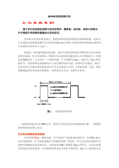
其工作原理是:控制信号由接收机的通道进入信号调制芯片,获得直流偏置电压。
它内部有一个基准电路,产生周期为20ms,宽度为1.5ms的基准信号,将获得的直流偏置电压与电位器的电压比较,获得电压差输出。
最后,电压差的正负输出到电机驱动芯片决定电机的正反转。
当电机转速一定时,通过级联减速齿轮带动电位器旋转,使得电压差为0,电机停止转动。
图1舵机的控制要求舵机的控制信号是PWM信号,利用占空比的变化改变舵机的位置。
一般舵机的控制要求如图1所示。
单片机实现舵机转角控制可以使用FPGA、模拟电路、单片机来产生舵机的控制信号,但FPGA成本高且电路复杂。
对于脉宽调制信号的脉宽变换,常用的一种方法是采用调制信号获取有源滤波后的直流电压,但是需要50Hz(周期是20ms)的信号,这对运放器件的选择有较高要求,从电路体积和功耗考虑也不易采用。
5mV以上的控制电压的变化就会引起舵机的抖动,对于机载的测控系统而言,电源和其他器件的信号噪声都远大于5mV,所以滤波电路的精度难以达到舵机的控制精度要求。
也可以用单片机作为舵机的控制单元,使PWM信号的脉冲宽度实现微秒级的变化,从而提高舵机的转角精度。
单片机完成控制算法,再将计算结果转化为PWM信号输出到舵机,由于单片机系统是一个数字系统,其控制信号的变化完全依靠硬件计数,所以受外界干扰较小,整个系统工作可靠。
单片机系统实现对舵机输出转角的控制,必须首先完成两个任务:首先是产生基本的PWM周期信号,本设计是产生20ms的周期信号;其次是脉宽的调整,即单片机模拟PWM信号的输出,并且调整占空比。
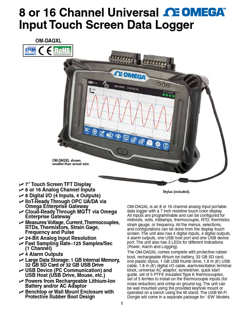
Omega OM-DAQXL 8 16通道多功能数据记录仪说明书
8 or 16 Channel UniversalInput Touch Screen Data LoggerU 7" Touch Screen TFT Display U 8 or 16 Analog Channel Inputs U 8 Digital I/O (4 Inputs, 4 Outputs)U I IoT-Ready Through OPC UA/DA via Omega Enterprise Gateway U C loud-Ready Through MQTT via Omega Enterprise Gateway U M easures Voltage, Current, Thermocouples, RTDs, Thermistors, Strain Gage, Frequency and Pulse U 24-Bit Analog Input Resolution U F ast Sampling Rate–125 Samples/Sec (1 Channel)U 4 Alarm Outputs U L arge Data Storage: 1 GB Internal Memory, 32 GB SD Card or 32 GB USB Drive U U SB Device (PC Communication) and USB Host (USB Drive, Mouse, etc.)U P owers from Rechargeable Lithium-Ion Battery and/or AC Adaptor U B enchtop or Wall Mount Enclosure with Protective Rubber Boot DesignOM-DAQXL shownsmaller than actual size.Stylus (included).OM-DAQXL is an 8 or 16 channel analog input portable data logger with a 7 inch resistive touch color display. All inputs are programmable and can be configured for millivolts, volts, milliamps, thermocouple, RTD, thermistor, strain gauge, or frequency. All the menus, selections, and configurations can be done from the display touch screen. The unit also has 4 digital inputs, 4 digital outputs, 4 alarm outputs, one USB host port and one USB device port. The unit also has 3 LEDs for different indications (Power, Alarm and Logging).The OM-DAQXL comes complete with protective rubber boot, rechargeable lithium ion battery, 32 GB SD card, one plastic stylus, 1 GB USB thumb drive, 1.8 m (6') USB cable, 1.8 m (6') digital I/O cable, alarm/excitation terminal block, universal AC adaptor, screwdriver, quick start guide, set of 5 PTFE insulated Type K thermocouples, set of 5 ferrites to install on the thermocouple inputs (for noise reduction) and crimp-on ground lug. The unit can be wall mounted using the provided keyhole mount or operated on a bench using the tilt stand. The USB Wi-Fi Dongle will come in a separate package for '-EW' Models.Data display areaLine graph display.Digital display.Home ScreenThe home screen is the main screen of the datalogger’s user interface. It is divided into 3 distinctsections as shown below.Digital Display ViewStatus/Information Display: This status bar providesinformation such as Battery Charge percentage,System Clock (displays current Time & Date), Lock/Unlock data logger, status of the 4 Alarm Outputs, andLogging Mode indication.The OM-DAQXL comes complete with hard carrying case,protective rubber boot, rechargeable lithium ion battery, 32 GBSD card, one plastic stylus, 1 GB USB thumb drive, 1.8 m (6')USB cable, 1.8 m (6') digital I/O cable, alarm/excitation terminalblock, universal AC adaptor, screwdriver, quick start guide, setof 5 PTFE insulated Type K thermocouples, set of 5 ferrites toinstall on the thermocouple inputs (for noise reduction) andcrimp-on ground lug. Not all items shown. See User Guide forinstructions on installing ferrites on the thermocouple inputs. Data Display Area: This is the area where differentinputs (up to 4 Channels) are displayed vs. time.The data is displayed in 4 different ways: Waveform,Waveform & Table, Table only, and Digital. In the Digitalview, each channel name and number are displayedalong with the value.Navigation Toolbar: This toolbar provides accessto all the functions and menus of the data logger.Y ou can extend or retract the toolbar by pressing theTool button. The following flow chart shows all thefunctionalities of the buttons of the toolbar.OM-DAQXL shown smaller than actual size.Standalone OperationThe OM-DAQXL’s touch screen user interface (UI)makes configuring the data logger for operationstraight forward and simple. Recorded data files caneasily be reviewed and analyzed on the OM-DAQXL.For data analysis on a computer, simply transfer thedata file from the SD card or USB thumb drive to thePC and open the selected data file into Excel® or otherdata analysis software.Toolbar FlowchartBack view, OM-DAQXLALARM, EXTERNAL TRIGGER & 24VLeft side view, OM-DAQXLRight side view, OM-DAQXLTop view, OM-DAQXLBottom view, OM-DAQXLFront view, OM-DAQXLETHERNET PORTUSB HOST PORTSHELL GROUND USB DEVICE PORTEthernet Port only available for -EW modelsSpecificationsScreen: 7 inch, TFT, resistive touch comes with plastic stylus Rubber Boot: Black4 Channels: 25 s/sec8 Channels: 10 s/sec16 Channels: 5 s/secLogging Rate: 125 s/sec (Max) to 1 s/hour (Min)Maximum Logging Rate per Number of Channels (Analog and Digital):1 Channel: 125 s/sec2 Channels: 50 s/sec4 Channels: 25 s/sec8 Channels: 10 s/sec16 Channels: 5 s/secExcitation to Power External Transmitter: 24 Vdc @ 50 mA output–set in data session settingFilter Options: Per channel selectable moving average filter: None, 2, 5, 10, 20 or 50 samplesNumber of Samples for Moving Average Filter per Channel: Up to 50 samplesMath (Virtual) Channels: 8 or 16Digital Inputs: 4 Schmitt trigger based inputsRange: 0 to 24 Vdc single-endedLogic High Threshold: 2.5V Alarms per Channel: T woAlarm Types: High, low, windows in, windows out, open sensor Alarm Latching: Settable in alarm menuOn Alarm Event: Map to 4 alarm outputs, take screen shot, sound buzzerLogging Conditions: On command or based on trigger conditionsStart and Stop Trigger Conditions: Timer, date and time, weekday and time, alarm output, external triggerMemory:Internal: 1 GBSD Card: 32 GBUSB Drive: 32 GBUSB Ports: One host and one deviceEthernet*: 10/100 Base-T, TCP/IPUSB Wi-Fi Dongle*: 802.11 b/g/n, USB 2.0 interface, up to 150 Mbps, WEP and WPA/WPA2 encryption schemes*Only available on -EW models.Battery: Rechargeablelithium-ion;**********Battery Life: 4 to 8 hours based on display settingDC Adaptor: 12 Vdc @ 5AOperating Environment: 0 to 50°C (32 to 122°F), 0 to 95% RH non-condensingGeneral Dimensions: 28.6 L x 15.24 H x 6.35 cm D(9 x 6 x 2.5")Note: Measurement accuracy is at room temperature after 30 minutes* Insert country code.Comes complete with hard carrying case, protective rubber boot, 32 GB SD card, 1 GB USB thumb drive, 1.8 m (6') USB cable, 1.8 m (6') digital I/O cable, alarm/excitation terminal block, universal AC adaptor, screwdriver, quick start guide, set of 5 PTFE insulated Type K thermocouples and crimp-on ground lug. USB Wi-Fi dongle will come in a separate package for -EW models.Ordering Example: OM-DAQXL-1-NA,8-channel touch screen data logger with USB host/device.OM-DAQXL with protective rubber boot removed(included). Shown smallerthan actual size.-EW models are compatible with USB Wi-Fi dongles that support Windows Embedded Compact 7.0.。
PCS-996_故障录波装置_说明书_国内中文_国内标准版_R1.01_ZL_GZLB5118.1306

严重的设备损坏。 警告! 意味着如果安全预防措施被忽视,则可能导致人员死亡,严重的人身伤害,
或严重的设备损坏。 警示! 意味着如果安全预防措施被忽视,则可能导致轻微的人身伤害或设备损坏。
本条特别适用于对装置的损坏及可能对被保护设备的损坏。 警告! 为增强或修改现有功能,装置的软硬件均可能升级,请确认此版本使用手册和您购买的产品相 兼容。 警告! 电气设备在运行时,这些装置的某些部件可能带有高压。不正确的操作可能导致严重的人身伤 害或设备损坏。 只有具备资质的合格专业工作人员才允许对装置或在装置临近工作。工作人员需熟知本手册中 所提到的注意事项和工作流程,以及安全规定。 特别注意,一些通用的工作于高压带电设备的工作规则必须遵守。如果不遵守可能导致严重的 人身伤亡或设备损坏。 危险! 在一次系统带电运行时,绝对不允许将与装置连接的电流互感器二次开路。该回路开路可能会 产生极端危险的高压。 警告! 曝露端子 在装置带电时不要触碰曝露的端子等,因为可能会产生危险的高电压。 残余电压 在装置电源关闭后,直流回路中仍然可能存在危险的电压。这些电压需在数秒钟后才会消失。
PCS-996R 故障录波装置 说明书
PCS-996 故障录波装置
前言 使用产品前,请仔细阅读本章节!
本章叙述了使用产品前的安全预防建议。在安装和使用时,本章内容必须全部阅读且充分理解。 忽略说明书中相关警示说明,因不当操作造成的任何损害,本公司不承担相应责任。 在对本装置做任何操作前,相关专业人员必须仔细阅读本说明书,熟悉操作相关内容。 操作指导及警告 本手册中将会用到以下指示标记和标准定义: 危险! 意味着如果安全预防措施被忽视,则会导致人员死亡,严重的人身伤害,或
南京南瑞继保电气有限公司
i
PCS-996 故障录波装置
Inmarsat EXPLORER 323 BGAN终端产品介绍说明书

Instant communicationSimply place the terminal on the roof - it is easily mounted with optional magnetic mounts - and connect your phone to the EXPLORER app or log onto the wireless network with your PC to turn the vehicle into a mobile communication hub.No moving partsThe beam switching antenna is ultra com-pact and lightweight (just 3.9 kg / 8.5 lbs), ideal for vehicles or trains on-the-move. It is designed for robust and durable use with no moving parts.Compact voice and broadband solution EXPLORER 323 is an ultra compact BGAN terminal for voice and data communication on-the-move, a perfect match for our Cobham PRISM PTT + solution.The one-piece system consists of a combined tranceiver and switched beam antenna with integrated wifi.Whether you’re engaged in humanitarian operations, cargo or rail transportation,telemedicine or emergency services, you need easy deployable communication equipment you can always rely on - regardless of time or place.No roamingBGAN offers mobile broadband connectivity wherever you go at fixed pricing with no roaming fees. With the EXPLORER 323 you know your cost of communication regardless of the number of borders you cross.First of its kindAs a vehicular terminal, EXPLORER 323 is the first terminal to obtain both Inmarsat Class 12 Type Approval and BGAN M2M Certification, enabling it to operate with traditional BGAN and BGAN M2M SIM cards.EXPLORER 323Ultra-compact comms-on-the-move BGAN terminal/satcomGeneralUser Interface: Status LED Web interfaceFactory default resetLanguages: UK, FR, DE, ES, RU, JP , CN, PT Approvals: CE, GMPCS, FCC, IC, RCM Inmarsat Class 12 andInmarsat M2M Type ApprovalInterfaces1 x WLAN interface Standard: 802.11 b/g1 x LAN interface Data rate:10/100 Mbps Combined DC power and Ethernet connectorCombined connector providing DC power input, ignition and Ethernet connectivityHybrid cable, wires: Power 2, Ignition 1, Ethernet 4 + 1 (shield)BGAN SIM-Card slotEnvironmental conditionsTemperature Operational: -25 to +55°C / -13 to 131°F Survival: -40 to +80°C / -40 to 176°F Storage:-40 to +85°C / -40 to 185°F Relative humidity: 95% non-condensingat +40°C / +104°FWater and dust (IP-rating)Terminal:IP66SpecificationsDimensions and Weight Height: 9.7 cm / 3.82 inches (incl. mounts)Width: Ø321 cm / Ø12.7 inches Weight: 3.9 kg / 8.5 lbsGlobal Services Voice: 4 kbps AMBE+2Standard IP (Rx/Tx): Up to 384 / 225 kbps (>20° elevation)Up to 270 / 158 kbps (>5° elevation)Streaming IP: 32, 64 kbps (>20° elevation) 32 kbps (>5° elevation)SMS:160 charactersOn-The-Move Communication IP Data and Voice: Services supported at vehiclespeeds up to 200 km/h (125 mph)Inmarsat frequencies: 1518.0 - 1525.0 MHz (Rx) (EMEA) 1525.0 - 1559.0 MHz (Rx) 1626.5 - 1660.5 MHz (Tx)1668.0 - 1675.0 MHz (Tx) (EMEA)PowerDC input range (nom.): 12 - 24VDC Power (max) @10.5-32V.:35WOther featuresEXPLORER Connect AppFor making telephone calls from your smartphone. Available for Android and iPhone.Set-up and Router FunctionalityWebserver , Built-in NAT Router , Admin control (pass-word protected), DHCP , Network Management, Remote Management, SIP Server , Point-to-Point Protocol over Ethernet (PPPoE)PackageEXPLORER 323 terminal (combined tranceiver and switched beam antenna). 6m combined DC power and Ethernet cable (open ended), installation guideProduct number403723A-00500EXPLORER 323 SystemAccessories403723A-009 Magnetic mount solution 403706A-050 EXPLORER Connection Box 403723A-06015m cable for 24V DC and Ethernet71-1691Subject to change without notice1455 N. Dutton, Suite A. Santa Rosa, CA 95401(707) 545-8199。
- 1、下载文档前请自行甄别文档内容的完整性,平台不提供额外的编辑、内容补充、找答案等附加服务。
- 2、"仅部分预览"的文档,不可在线预览部分如存在完整性等问题,可反馈申请退款(可完整预览的文档不适用该条件!)。
- 3、如文档侵犯您的权益,请联系客服反馈,我们会尽快为您处理(人工客服工作时间:9:00-18:30)。
ANPEC reserves the right to make changes to improve reliability or manufacturability without notice, and advise customers to obtain the latest version of relevant information to verify before placing orders.APM9968CO
Features
Applications
Pin Description
Ordering and Marking Information
N-Channel MOSFET
APM9968C
Handling Code Tem p. Range Package Code
Package Code O : TSSOP-8
Operating Junction Tem p. Range C : -55 to 150°C Handling Code
TU : Tube TR : Tape & Reel Lead Free Code
L : Lead Free Device Blank : Original Device APM9968C O :
APM9968C XXXXX
XXXXX - Date Code
Lead Free Code T op View of TSSOP − 8
• 20V/6A , R DS(ON)=16m Ω(typ.) @ V GS =4.5V
R DS(ON)=20m Ω(typ.) @ V GS =2.5V
• Super High Dense Cell Design for Extremely
Low R DS(ON)
• Reliable and Rugged • TSSOP-8 Packages
• Lead Free Available (RoHS Compliant)
• Power Management in Notebook Computer,
Portable Equipment and Battery Powered Systems
• Zener Diode Protected Gate Provide Human
Body Mode Electrostatic Discharge Protection to 2500 V
(1)(8)(4)(2)
(3)
(6)(7)
G1
Note: ANPEC lead-free products contain molding compounds/die attach materials and 100% matte in plate termina-tion finish; which are fully compliant with RoHS and compatible with both SnPb and lead-free soldiering operations.ANPEC lead-free products meet or exceed the lead-free requirements of IPC/JEDEC J STD-020C for MSL classifica-tion at lead-free peak reflow temperature.
APM9968CO
Absolute Maximum Ratings (T A = 25°C unless otherwise noted)
*Surface Mounted on 1in2 pad area, t ≤ 10sec.
Electrical Characteristics (T A = 25°C unless otherwise noted)
APM9968CO
Electrical Characteristics (Cont.) (T A = 25°C unless otherwise noted)
a : Pulse test ; pulse width≤300µs, duty cycle≤2%.
b : Guaranteed by design, not subject to production testing.
APM9968CO
1E-4
1E-30.010.111030
1E-3
0.01
0.1
1
2
Typical Characteristics
I D - D r a i n C u r r e n t (A )
Drain Current
T j - Junction Temperature (°C)
Safe Operation Area
V DS - Drain - Source Voltage (V)Thermal Transient Impedance
Square Wave Pulse Duration (sec)
Power Dissipation
P t o t - P o w e r (W )
T j - Junction T emperature (°C)
I D - D r a i n C u r r e n t
(A )
20
40
60
80100120140160
0.0
0.3
0.6
0.9
1.2
1.5
20
40
60
80
100120140160
2
4
6
8
0.010.1
1
10100
0.010.1
1
10
100
N o r m a l i z e d T r a n s i e
n t T h e r m a l R e s i s t a n c e
I D - Drain Current (A)
T j - Junction T emperature (°C)
Gate Threshold Voltage
V GS - Gate - Source Voltage (V)
I D - D r a i n C u r r e n t (A )
04
8
12
16
20
APM9968CO
V DS - Drain - Source Voltage (V)
Drain-Source On Resistance
T j - Junction T emperature (°C)C - C a p a c i t a n c e (p F )
Source-Drain Diode Forward
I S - S o u r c e C u r r e n t (A )
Capacitance
Q G - Gate Charge (nC)
V G S - G a t e - s o u r c e V o l t a g e (V )
Typical Characteristics (Cont.)
-50-25
25
50
75
100125150
0.1
1
10
200
500
1000
1500
2000
2500
04812162024
1
2
3
4
5
APM9968CO Packaging Information TSSOP-8
APM9968CO
T L
T P
25
T e m p e r a t u r e
Tim e
Reflow Condition (IR/Convection or VPR Reflow)
Classification Reflow Profiles
Physical Specifications
APM9968CO
Classification Reflow Profiles(Cont.)
Reliability Test Program
Carrier Tape & Reel Dimensions
APM9968CO
Carrier Tape & Reel Dimensions(Cont.)
Cover Tape Dimensions
Customer Service
Anpec Electronics Corp.
Head Office :
5F, No. 2 Li-Hsin Road, SBIP,
Hsin-Chu, T aiwan, R.O.C.
T el : 886-3-5642000
Fax : 886-3-5642050
Taipei Branch :
7F, No. 137, Lane 235, Pac Chiao Rd.,
Hsin Tien City, Taipei Hsien, T aiwan, R. O. C.
T el : 886-2-89191368
Fax : 886-2-89191369。
