TC55V1001F-85L中文资料
超级密码——精选推荐

0000超级密码台达变频器的超级密码-B系列的:57522台达变频器的超级密码-H系列的:33582欧瑞变频器(也就是之前的惠丰变频器)超级密码是: 1888,1500-G 1500-P 1000-G 200-G的都是通用的烁普变频高级菜单P301输入321 MD320(汇川)万能密码是18181A000输入11,刷新程序P301输入321A000输入9,进菜单发布英威腾万能密码供大家分享50112型号CHV CHE CHF 在参数P7-00内不管设多少密码,它的万能密码是:50112部分变频器万能密码(好东西啊!分享一下)1、台达变频器的超级密码-B系列的:57522台达变频器的超级密码-H系列的:33582台达S1系列变频的万能密码:575222、欧瑞变频器(也就是之前的惠丰变频器)超级密码是:18881500-G 1500-P 1000-G 200-G的都是通用的。
3、烁普变频高级菜单P301输入321A000输入11,刷新程序P301输入321A000输入9,进菜单E001,输入机器G,PE002额定电压E003额定电流E004电压校正E005不动E006电流校正4、普传PI2000刷新设定方法(1)将C01设定为222进入P14(2)将P14设定3对CPU刷新,这时显示PI2000将C01设为222进入P14参数设定,P14设为2,P01为设定机型为G、F,P02设定变频器电压380V,P03设定变频器额定电流,P04设定电压显示,P05设定电流显示。
5、英威腾万能密码50112型号CHV、CHE 、CHF在参数P7-00内不管设多少密码,它的万能密码是:5 01126、没密码进不去,三菱740的把面板拔下来再插上就行。
7、爱默生TD3000的密码8888爱默生TD3300的密码20028、西林变频器的万能密码:6860 (以前是,现在大家试试看)。
9、ABB ACS600变频器完全参数密码NAMC主控板参数设置:1、在16.03参数中输入密码:23032、102.01参数设置为:false可以进入设定所有主控板参数。
78 ZIEHL industrie-elektronik UFR1001E 电压频率监测器商品说明

Voltage Monitoring Type UFRThe grid- and plant protection de-vice UFR1001E monitors voltage and frequency in plants for own generation of electricity. It com-plies with the requirements of VDE-AR-N 4105:2018-11, VDE-AR-N 4110:2018-11, G98, G99, ÖVE/ÖNORM E 8001-4-712:2009 and other standards for generators connected to the public grid.The UFR1001E is a dual-channel device and thus one-fault-proof.Voltage and Frequency Relay UFR1001EGrid- and Plant Protection VDE-AR-N 4105 and 4110, ÖVE-standard, G98 + G99, DIN V VDE 0126-1-1, VFR2013/2014, NRS 0972-1:2017 Ed 2, Synergrid C10/C11UFR1001E••••••••NEW: VDE-AR-N 4105:2018-11, VDE-AR-N 4110:2018-11Part number:S222296The function of the output-relays and of the connected switches can be monitored with feed-back contacts. When a connected switch does not switch off, the UFR does not switch on again. When a switch does not switch on it makes 2 restarts and thus improves availability of monitored plant.The limits are pre-set according to VDE-AR-N 4105-2018-11, VDE-AR-N 4105:2018-11 and other standards. They can be changed if required and be protected with a code and/or a seal.With a 2-step test both channels can be tested indivi-dually and the triggering time of connected switches is measured.The standby input allows a remote shutoff e.g. with a RCR.Under and overvoltage monitoring 15…520 VMeasuring phase-neutral or phase-phaseMonitoring of under- and overfre-quency 45…65 HzMonitoring of quality of voltage (10-minutes-average)Monitoring of vector shift 2…65°Monitoring of rate of change of frequency (ROCOF, df/dt) 0,100...5,000 Hz/sOne-fault-proof with monitoring of connected switches (defeatable), 2 automatic restarts at errorPassive anti-islanding pro-tection acc. to ch. 6.5.3 and app. D2Switching delay adjustable 0.05 … 300 sSwitching back delay adju-stable 0 … 6.000 s Preset values acc. toVDE-AR-N 4105:2018-11 (Pr2), VDE-AR-N 4105-2011-08 (Pr1)VDE-AR-N 4110:2018-11 (PR11-14) and BDEW (Pr 3-6)G98 (G83/2) and G99 (G59/3) for Great Britain ÖVE standard for AustriaVSE/EEA-CH 2014 for SwitzerlandAlarm counter for 100 alarms (trip value, cause and rel. time stamp)Record of added times of alarmsInput for standby with counter and recording of time Test button and simulation with measuring of switching-timesSealing. All values can be read-out when sealed Easy installation and programming with pre-set programsHousing for DIN-rail-mount, 105 mm wide, mounting height 66 mm•••••••••••-----Certificate of conformity Grid and Plant protection acc. to VDE-AR-N 4105 2011-08 and 2018-11 "Plants for generati-on of own energy in low voltage grid"Cerfiticate of conformity Grid and Plant protection acc. to BDEW requirement "Plants for generation of own energy in medium voltage grid"Certificates:CertificateÖVE/ÖNORM E 8001-4-712:2009-12, Anhang ACertificate of compliance DIN V VDE 0126-1-1Certificate de conformitéDIN V VDE 0126-1-1, VFR2013/VFR 2014Certificate of complianceNRS 097-2-1:2010 ed 2.0 South Africa approved Synergrid C10/C11approved Energex RED STD00233accepted by TepcoCertificate of compliance EN 50438:2013Certificate of compliance G59/3:2013, G83/2:2012, G99/1-1+2+3:2018 and G98/1-1+2:2018RD1699:2011 / RD413:2014Technical Data UFR1001EVoltage Monitoring Type UFR2AC/DC 24-270 V, 0/45...65 Hz, <5VA DC: 20,4...297 V, AC: 20,4...297 V 2 change-over contacts see operating manualAC 15...530 V (< 5 V display: 0)AC 15...520 VAC 10...310 V (< 5 V display: 0)AC 15...300 V true RMSadjustable 1,0...180 Vwith neutral: ±0,6% of measured value without neutral: ±0,8% of measured value >100V: -1 digit (resolution 1 V) <100V: -1 digit (resolution 0,1 V)3-phase with / without neutraladjustable 0,05 (± 15ms)...300,0 sadjustable 0 (approx. 200 ms)...6.000 s 40...70 Hz45,00...65,00 Hz 0,05...10,00 Hz ± 0,04 Hz ± 1 digitadjustable 0,05 (± 15ms)...300,0 s adjustable 0 (>200 ms)...6.000 s 0...90,0°2,0...65,0°< 50 msadjustable 3...240 s adjustable 2...20 s0,100...5,000 Hz/s, 4...50 cycles DC 4,5...27 Vmax. 20 mA / output DC 15...35 Vadjustable 0,5...99,0 sEN 602554000 V III 2300 V 100 %-20 °C...+55 °C -25 °C...+70 °C3K5 (except condesation and formation of ice)EN 61 000-6-2EN 61 000-6-3V690 x 105 x 69 mm, mounting height 66 mm IP30IP20DIN-rail 35 mm according to EN 60 715 or screws M4ca. 250 gPower supply Rated supply voltage UsMeasurement phase-phase Setting range phase-phaseMeasuring voltage phase-neutral Setting range phase-neutral Measurement method HysteresisMeasurement accuracy Accuracy of display Measurement functions Switching-delay (dAL)Switching-back-delay (doF)Measurement range Setting range HysteresisMeasurement accuracy Switching delay (dAL)Switching-back-delay (doF)Measurement range Setting rangeSwitching-delay (dAL)Switching-back-delay (doF)Delay at Us on Setting range Voltage I1Current Q1...Q5Voltage Y0...Y1/2Switching time connected swit-chesRated impulse voltage Overvoltage category Pollution degreeRated Insulation voltage Ui Operating timeOperating temperature Storage temperatureClimatic conditions (IEC/EN 60721-3-3)EMC - immunity EMC - emissionDesignDimensions (h x w x d) Protection housing Protection terminals Attachment WeightHousingRelay output Test ConditionsVoltageFrequencyVector-ShiftDigital outputs insulated Input Feed-back-contactsROCOF (df/dt)。
EUCHIPS EUCP50XY-1WxxxxC-0MWWZ LED 恒流调光驱动器 产品说明书

SHANGHAI EUCHIPS INDUSTRIAL CO.,LTDEUCP50XY-1WxxxxC-0MWWZProduct FeaturesLED 恒流调光驱动器概述EUCP50XY-1WxxxxC-0MWWZ 系列是恒流模式输出的LED 驱动器,抗浪涌等级高,防护等级为IP67,适用于户外。
用户可根据调光方式和市场需求选择相应的型号,并可通过NFC 编程器修改输出电流。
电源电压: 100-277VAC 或 141-391VDC 10kV 浪涌等级- 60℃低温启动(可选择) 100,000小时的寿命@ Tc=75C 5 年保修 @ Tc<=80C Airset TM NFC 编程电流输出精度+/-2% (可编程模型) 0-10V/PWM/DALI 可调光 (取决于型号) 调灭后待机功耗0.5W(取决于型号)电源控制器与风扇的辅助电源为12V 300mA (取决于型号) 输入过压保护(可选择)UL Class P , Class 2,ENEC/CB/CCC,SELV 认证 安全依据EN 61347-1, 61347-2-3,61347-2-13, 62384 应用 :LED 灯带、景观灯、工矿灯、路灯、泛光灯上海欧切斯实业有限公司型号清单 技术参数上海欧切斯实业有限公司注: 除非特别注明,所有的测试结果均在220VAC ,25℃室温下测得。
* 可选择标记项目,获取详细功能请联系销售人员调光安规/电磁兼容调调光光曲曲线线a. 带调灭功能默认值)b. 无调灭功能(联系销售获取此功能调光接线图(End of Life: Maximum Failure Rate=10%)使用寿命 vs. 外壳温度功率因数vs.负载THD vs.负载EUCP50NN(FR)-1WxxxxC-0MWWUUnspecified tolerance :±1AC INPUT(UL SJTW 3×18AWG)DC OUTPUT(UL SJTW 2×18AWG)BLACK(ACL)WHITE(ACN)GREEN(GND)RED(V+)BLUE(V-)效率 vs.负载 (1050mA)尺寸 (mm)EUCP50AR(AN)-1WxxxxC-0MWWUUnspecified tolerance :±1AC INPUT(UL SJTW 3×18AWG)DC OUTPUT(UL SJTW 2×18AWG)DIMMING WIRE(UL SJTW 2×18AWG)BLACK(ACL)WHITE(ACN)GREEN(GND)PURPLE(Vdim+)GRAY(Vdim-)RED(V+)BLUE(V-)EUCP50ER-1WxxxxC-0MWWUUnspecified tolerance :±1AC INPUT(UL SJTW 3×18AWG)DC OUTPUT(UL SJTW 2×18AWG)DIMMING WIRE(UL SJTW 3×18AWG)BLACK(ACL)WHITE(ACN)GREEN(GND)BLACK&WHITE(Vaux/+12V)PURPLE(Vdim+)GRAY(Vdim-)RED(V+)BLUE(V-)EUCP50DR-1WxxxxC-0MWWUUnspecified tolerance :±1AC INPUT(UL SJTW 3×18AWG)DC OUTPUT(UL SJTW 2×18AWG)DIMMING WIRE(UL 2464 4×22AWG)BLACK(ACL)WHITE(ACN)GREEN(GND)RED(V+)BLUE(V-)PINK(DALI 2)BLACK&WHITE(Vaux+)GRAY(Vaux-)BLUE&WHITE(DALI 1)EUCP50NN(FR)-1WxxxxC-0MWWSUnspecified tolerance :±1AC INPUT(VDE H05RN-F 3×1.0mm2)DC OUTPUT(VDE H05RN-F 2×1.0mm2)BROWN(ACL)BLUE(ACN)YELLOW&GREEN (GND)BROWN(V+)BLUE(V-)EUCP50AR(AN)-1WxxxxC-0MWWSUnspecified tolerance :±1AC INPUT(VDE H05RN-F 3×1.0mm2)DC OUTPUT(VDE H05RN-F 2×1.0mm2)DIMMING WIRE(H05RN-F 2×0.75mm2)BROWN(ACL)BLUE(ACN)YELLOW&GREEN (GND)PURPLE(Vdim+)GRAY(Vdim-)BROWN(V+)BLUE(V-)EUCP50ER-1WxxxxC-0MWWSUnspecified tolerance :±1AC INPUT(VDE H05RN-F 3×1.0mm2)DC OUTPUT(VDE H05RN-F 2×1.0mm2)DIMMING WIRE(H05RN-F 3×0.75mm2)BROWN(ACL)BLUE(ACN)YELLOW&GREEN (GND)BLACK&WHITE(Vaux/+12V)PURPLE(Vdim+)GRAY(Vdim-)BROWN(V+)BLUE(V-)EUCP50DR-1WxxxxC-0MWWSUnspecified tolerance :±1AC INPUT(VDE H05RN-F 3×1.0mm2)DC OUTPUT(VDE H05RN-F 2×1.0mm2)DIMMING WIRE(H05RN-F 4×0.5mm2)BROWN(ACL)BLUE(ACN)YELLOW&GREEN (GND)BROWN(V+)BLUE(V-)PINK(DALI 2)BLACK&WHITE(Vaux+)GRAY(Vaux-)BLUE&WHITE(DALI 1)。
TC55系列运动控制器说明书--工业品大狗
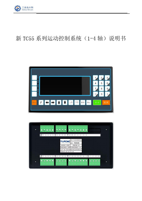
新TC55系列运动控制系统(1-4轴)说明书1.安全须知使用本控制系统前,请您仔细阅读本手册后再进行相关的操作。
仔细阅读本操作说明书,以及用户安全须知,采取必要的安全防护措施。
如果用户有其他需求,请与本公司联系。
工作环境及防护:1.控制系统的工作温度为0-40℃,当超出此环境温度时系统可能会出现工作不正常甚至死机等现象。
温度过低时,液晶显示器将出现不正常的情况。
2.相对湿度应控制在0-85%。
3.在高温、高湿、腐蚀性气体的环境下工作时,必须采取特殊的防护措施。
4.防止灰尘、粉尘、金属等杂物进入控制系统。
5.应防护好控制系统的液晶屏幕(易碎品):使其远离尖锐物体;防止空中的物体撞到屏幕上;当屏幕有灰尘需要清洁时,应用柔软的纸巾或棉布轻轻擦除。
系统的操作:系统操作时需按压相应的操作按键,在按压按键时,需要食指或中指的指肚按压,切忌用指甲按压按键,否则将造成按键面膜的损坏,而影响您的使用。
初次进行操作的操作者,应在了解相应功能的正确使用方法后,方可进行相应的操作,对于不熟悉的功能或参数,严禁随意操作或更改系统参数。
由于使用产品不当,而造成危及人身、财产安全的责任,本公司概不负责。
系统的检修:当系统出现不正常的情况,需检修相应的连接或插座连接处时,应先切断系统电源。
再进行必要的检修。
未进行严格操作的技术人员或未得到本公司授权的单位或者个人,不能打开控制系统进行维修操作,否则后果自负。
系统保修说明:保修期:本产品自出厂之日起十二个月内。
保修范围:在保修期内,任何按使用要求操作的情况下所发生的故障。
保修期内:保修范围以外的故障为收费服务。
保修期外:所有的故障均为收费服务。
以下情况不在保修范围内:任何违反使用要求的人为故障或意外故障,尤其电压接反接错。
带电插拔系统连接插座而造成的损坏。
自然灾害等原因导致的损坏。
未经许可,擅自拆卸、改装、修理等行为造成的损坏。
其他事项:本说明书如有与系统功能不符、不详尽处,以系统软件功能为准。
常用集成芯片
常用芯片作用2007-07-30 16:40mc2831(mc2833)低功耗FM发射机mc3362低功耗FM接收机CXA1691BM收音机FM/AM接收芯片双音频编码器件是HM9187,解码芯片是MT8870(注意:HM9187输出的双音频信号幅值太大了,串联一个160K的电阻,送到M 幅度,幅度过高会导致窄带FM的调制/解调出问题.)ICL8038 单片集成压控波形发生器(应用广泛),在0.01~300kHz的范围里可以同时产生正弦波、矩形波和三角波。
使用时只作为压控振荡器、调频信号发生器或单片函数发生器。
其输出电平特性为:方波0.2V suppl y(2mA);三角波幅度为0.33V suppl y,输出阻22V supply,输出阻抗典型值为1kΩ。
MC145151 -2 锁相环芯片,是MC145151-1的性能改进产品,功耗降低而ESD和锁定性能则大有改进。
MC145151-2分别用N计数器和R计数器编程。
本器件集成了参考振荡器、可选参考频率分频器、数字相位鉴相器和14位可编程的除N计数器。
该芯工艺而具有低功耗,电压范围为3~9V;具有片上或离片参考振荡器的操作条件;有两路鉴相信号输出,其中PD out是鉴相器A的是鉴相误差信号,LD用来输出相位锁定信号;除N的范围为3~16383;8个用户可选的除R值分别为8、128、256、512、1应RA2~RA0从000到111的8个状态。
1.音频pcm编码DA转换芯片cirrus logic的cs4344,cs4334 。
4334是老封装,据说已经停产,4344封装比较小,非常好用2.音频放大芯片4558,LM833,5532,此二芯片都是双运放。
3.244和245,由于244是单向a=b的所以只是单向驱动。
而245是用于数据总线等双向驱动选择。
同时245的封装走线非常适4.373和374,地址锁存器,5.max232和max202,max3232 TTL电平转换6.网络接口变压器。
BS62LV1600FI55中文资料

BS62LV1600FI55中⽂资料Very Low Power CMOS SRAM 2M X 8 bitBS62LV1600Pb-Free and Green package materials are compliant to RoHSn FEATURESWide V CC operation voltage : 2.4V ~ 5.5V Very low power consumption : V CC = 3.0V Operation current : 46mA (Max.) a t 55ns 2mA (Max.) at 1MHz Standby current : 1.5uA (Typ.) at 25 O C V CC = 5.0V Operation current : 115mA (Max.) a t 55ns 10mA (Max.) a t 1MHz Standby current : 6.0uA (Typ.) at 25O C ? High speed access time : -55 55ns (Max.) at V CC :3.0~5.5V -70 70ns (Max.) at V CC : 2.7~5.5V ? Automatic power down when chip is deselected ? Easy expansion with CE1, CE2 and OE options ? Three state outputs and TTL compatible ? Fully static operation ? Data retention supply voltage as low as 1.5V n DESCRIPTIONThe BS62LV1600 is a high performance, very low power CMOS Static Random Access Memory organized as 2048K by 8 bits and operates form a wide range of 2.4V to 5.5V supply voltage.Advanced CMOS technology and circuit techniques provide both high speed and low power features with typical CMOS standby current of 1.5uA at 3.0V/25O C and maximum access time of 55ns at 3.0V/85O C.Easy memory expansion is provided by an active LOW chip enable (CE1), an active HIGH chip enable (CE2), and active LOW output enable (OE) and three-state output drivers.The BS62LV1600 has an automatic power down feature, reducing the power consumption significantly when chip is deselected. The BS62LV1600 is available in JEDEC standard 44-pin TSOP II and 48-ball BGA package.n POWER CONSUMPTIONPOWER DISSIPATIONSTANDBY(I CCSB1, Max)Operating(I CC , Max)V CC =5.0V V CC =3.0V PRODUCT FAMILYOPERATING TEMPERATUREV CC =5.0V V CC =3.0V1MHz10MHzf Max. 1MHz10MHzf Max.PKG TYPEBS62LV1600EC TSOP II-44 BS62LV1600FC Commercial +0O C to +70O C 50uA 8.0uA 9mA 48mA 113mA 1.5mA 19mA 45mABGA-48-0912 BS62LV1600EITSOP II-44 BS62LV1600FIIndustrial -40O C to +85O C100uA 16uA 10mA 50mA 115mA 2mA 20mA 46mABGA-48-0912n PIN CONFIGURATIONSn BLOCK DIAGRAMBrilliance Semiconductor, Inc. reserves the right to change products and specifications without notice.G H F E D C B A 1 2 3 4 5 6 A9 A11 A10 A19A12 A14 A13 A15 WE NC NC NC DQ7 A17 A16 A7 VSS VCC DQ2 DQ1 DQ6 DQ5 NC A5 OE A3 A0 A6 A4 A1A2CE2 NC NC NCCE1 DQ4 NC 48-ball BGA top view NC NC DQ0 VSS VCC DQ3 NC A18 A20 A8n TRUTH TABLEn ABSOLUTE MAXIMUM RATINGS (1)SYMBOL PARAMETER RATING UNITSV TERM Terminal Voltage withRespect to GND-0.5(2) to 7.0 VT BIAS Temperature UnderBias-40 to +125 O CT STG Storage Temperature -60 to +150 O CP T Power Dissipation 1.0 WI OUT DC Output Current 20 mA1. Stresses greater than those listed under ABSOLUTE MAXIMUM RATINGS may cause permanent damage to the device. This is a stress rating only and functional operation of the device at these or any other conditions above those indicated in the operational sections of this specification is not implied. Exposure to absolute maximum rating conditions for extended periods may affect reliability.2. –2.0V in case of AC pulse width less than 30 ns. n OPERATING RANGERANGAMBIENTTEMPERATUREV CC Commercial 0O C to + 70O C 2.4V ~ 5.5VIndustrial -40O C to + 85O C 2.4V ~ 5.5Vn CAPACITANCE (1) (T A = 25O C, f = 1.0MHz) SYMBOL PAMAMETER CONDITIONS MAX. UNITS C INInputCapacitanceV IN = 0V 10 pFC IOInput/OutputCapacitanceV I/O = 0V 12 pF1. This parameter is guaranteed and not 100% tested.n DC ELECTRICAL CHARACTERISTICS (T A =-40O C to +85OC)1. Typical characteristics are at T A =25O C and not 100% tested.2. Undershoot: -1.0V in case of pulse width less than 20 ns.3. Overshoot: V CC +1.0V in case of pulse width less than 20 ns.4. F MAX =1/t RC.5. I CC(MAX.) is 45mA/113mA at V CC =3.0V/5.0V and T A =70O C.6. I CCSB1(MAX.) is 8.0uA/50uA at V CC =3.0V/5.0V and T A =70O C.n DATA RETENTION CHARACTERISTICS (T A = -40O C to +85OC)1. V CC =1.5V, T A =25O C and not 100% tested.2. t RC = Read Cycle Time.3. I CCRD(Max.) is4.0uA at T A =70O C.n LOW V CC DATA RETENTION WAVEFORM (1) (CE1 Controlled)Data Retention Mode V CCt CDRV CC t RV IHV IHCE1≧V CC - 0.2V V DR ≧1.5V CE1V CCn LOW V CC DATA RETENTION WAVEFORM (2) (CE2 Controlled)n AC TEST CONDITIONS (Test Load and Input/Output Reference)Input Pulse Levels Vcc / 0V Input Rise and Fall Times 1V/ns Input and Output Timing Reference Level 0.5Vcc t CLZ , t OLZ , t CHZ , t OHZ , t WHZ C L = 5pF+1TTL Output LoadOthersC L = 30pF+1TTL1. Including jig and scope capacitance.n KEY TO SWITCHING WAVEFORMSn AC ELECTRICAL CHARACTERISTICS (T A = -40O C to +85OC)READ CYCLECE2 Data Retention Mode V CC t CDR V CC t R V ILV IL V CCV DR ≧1.5V CE2≦0.2V 1 TTL ALL INPUT PULSES→← 90%V CC GND Rise Time : 1V/ns Fall Time : 1V/ns90%→← 10%10%n SWITCHING WAVEFORMS (READ CYCLE)READ CYCLE 1 (1,2,4)READ CYCLE 2 (1,3,4)READ CYCLE 3 (1, 4)NOTES:1. WE is high in read Cycle.2. Device is continuously selected when CE1 = V IL and CE2= V IH .3. Address valid prior to or coincident with CE1 transition low and/or CE2 transition high.4. OE = V IL .5. Transition is measured ± 500mV from steady state with C L = 5pF. The parameter is guaranteed but not 100% tested. t RC t OHt AA D OUT ADDRESS t OHD OUTCE2 CE1D OUTCE2 CE1 OE ADDRESSn AC ELECTRICAL CHARACTERISTICS (T A = -40OC to +85OC)WRITE CYCLEn SWITCHING WAVEFORMS (WRITE CYCLE)WRITE CYCLE 1 (1)t WCt WR1(3)t CW(11)t CW(11)t WP(2)t AWt OHZ(4,10)t AS t WR2(3)t DHt DWD IND OUTWECE2CE1OEADDRESS(5)(5)WRITE CYCLE 2 (1,6)NOTES:1. WE must be high during address transitions.2. The internal write time of the memory is defined by the overlap of CE1 and CE2 active and WE low. All signals must be active to initiate a write and any one signal can terminate a write by going inactive. The data input setup and hold timing should be referenced to the second transition edge of the signal that terminates the write.3. t WR is measured from the earlier of CE1 or WE going high or CE2 going low at the end of write cycle.4. During this period, DQ pins are in the output state so that the input signals of opposite phase to the outputs must not be applied.5. If the CE1 low transition or the CE2 high transition occurs simultaneously with the WE low transitions or after the WE transition, output remain in a high impedance state.6. OE is continuously low (OE = V IL ).7. D OUT is the same phase of write data of this write cycle. 8. D OUT is the read data of next address.9. If CE1 is low and CE2 is high during this period, DQ pins are in the output state. Then the data input signals of opposite phase to the outputs must not be applied to them. 10. T ransition is measured ± 500mV from steady state with C L = 5pF. The parameter is guaranteed but not 100% tested. 11. t CW is measured from the later of CE1 going low or CE2 going high to the end of write.D IND OUTWE CE2 CE1ADDRESSn ORDERING INFORMATIONBSI (Brilliance Semiconductor Inc.) assumes no responsibility for the application or use of any product or circuit described herein. BSI does not authorize its products for use as critical components in any application in which the failure of the BSI product may be expected to result in significant injury or death, including life-support systems and critical medical instruments.n PACKAGE DIMENSIONSTSOP II-44n PACKAGE DIMENSIONS (continued)3: SYMBOL "N" IS THE NUMBER OF SOLDER BALLS.1: CONTROLLING DIMENSIONS ARE IN MILLIMETERS. 2: PIN#1 DOT MARKING BY LASER OR PAD PRINT.N EDNOTES:4812.09.0E1D1e3.755.250.75 48 mini-BGA (9mm x 12mm)n Revision HistoryRevision No. History Draft Date Remark2.2 Add Icc1 characteristic parameter Jan. 13, 2006Improve Iccsb1 spec.I-grade from 220uA to 100uA at 5.0V20uA to 16uA at 3.0VC-grade from 110uA to 50uA at 5.0V10uA to 8.0uA at 3.0V2.3 Change I-grade operation temperature range May. 25, 2006 - from –25O C to –40O C。
MIL-DTL-5541F--中英文版

超级中文标准网超级中文标准网MIL-DTL-5541F11 July 2006 2006年7月11日SUPERSEDING 替代MIL-C-5541E30 November 1990 1990年11月30日DETAIL SPECIFICATION规范说明CHEMICAL CONVERSION COATINGSON ALUMINUM AND ALUMINUM ALLOYS铝和铝合金表面化学防护涂层This specification is approved for use by all Departments and Agencies of the Department of Defense.该规范适用于美国国防部所有部门和机构1. SCOPE1.范围1.1Scope. This specification covers chemical conversion coatings formed by the reaction of chemical conversion materials with the surfaces of aluminum and aluminum alloys1.1范围. 该规范适用于铝制品和铝合金表面由于化学材料反应而形成的防护涂层。
1.2Classification. The chemical conversion coatings are of the following types and classes.1.2分类.化学转换涂层分为以下类型和级别.1.2.1T ypes. The chemical conversion coatings are of the following types (see 3.1):1.2.1型号.化学转换涂层分为以下类型(见3.1):Type I – Compositions containing hexavalent chromium.型号I-成分包含六价铬。
HN58C1001FPI-15中文资料
HN58C1001 Series
AC Characteristics (Ta = 0 to +70°C, VCC = 5.0 V ± 10%)
Test Conditions • Input pulse levels: 0.4 V to 2.4 V 0 V to VCC (RES pin) • Input rise and fall time: ≤ 20 ns • Output load: 1TTL Gate +100 pF • Reference levels for measuring timing: 0.8 V, 2.0 V Read Cycle
HN58C1001-15 Parameter Address to output delay CE to output delay OE to output delay Address to output hold OE (CE) high to output float* RES low to output float RES to output delay
VIH VIH × VIL VIL ×
Notes: 1. Refer to the recommended DC operating conditions. 2. × : Don’t care
Absolute Maximum Ratings
Parameter Supply voltage relative to VSS Input voltage relative to VSS Operating temperature range*
RES A3 WE A2 A1 A13 A0 I/O0 A8 I/O1 A9 I/O2 A11 VSS OE I/O3 A10 I/O4 I/O5 CE I/O6 I/O7 I/O7 I/O6 CE A10 I/O5 OE I/O4 I/O3
巴鲁夫 工业 RFID系统 产品手册说明书

Industrial RFID systems MANAGING ALL YOUR DATABalluff offers you a wide selection of data carriers and read/write heads for LF, HF and UHF applications. With the BIS V multi-frequency processor unit, all systems can be combined with each other. This adds flexibility and saves costs through lower inventory levels.Industrial RFID systems – managing all your dataAutomatic identification and tracking in productionTHE PERFORMANCE RANGEYour Balluff solutionsn HF RFID system (13.56 MHz) BIS M n LF RFID system (70/455 kHz) BIS C n LF RFID system (125 kHz) BIS L n UHF RFID system (860/960 MHz) BIS UGo online to individually configure your own system www.balluff.de/go/rfid-configuratorIO-LINK ALL-IN-ONE BIS V PROCESSOR UNIT1 Network block2 Read/write heads with IO-Link3 Data carriers4 Read/write heads with integrated processor unit5 Universal processor unit6 Read/write heads2266433315UHF by country-specific frequencies1 South Korea LF: 125 kHz HF: 13.56 MHzUHF: 917...920.8 MHz 2 JapanLF: 125 kHz HF: 13.56 MHzUHF: 916.7...920.8 MHz 3 ChinaLF: 125 kHz HF: 13.56 MHzUHF: 840.5...844.5 MHz 4 AustraliaLF: 125 kHz HF: 13.56 MHz UHF: 920...926 MHz5 South Africa LF: 125 kHz HF: 13.56 MHzUHF: 865.6...867.6 MHz 6 EuropeLF: 125 kHz HF: 13.56 MHzUHF: 865.6...867.6 MHz 7 USA/Canada/Mexico LF: 125 kHz HF: 13.56 MHz UHF: 902...928 MHz 8 BrazilLF: 125 kHz HF: 13.56 MHzUHF: 902...907.5 MHzWHAT ARE THECONSEQUENCES OF THE DIFFERENT FREQUENCIES?Briefly stated, different frequencies mean different working ranges, since the frequency determines the range. The frequency also affects the coupling behavior (see: How the system components communicate).LF is best suited for close range and for difficult conditions such as metallic surroundings. LF is therefore often used in tool identification.HF is ideal for parts tracking at close range up to 400 mm. With HF you can process and store larger quantities of data at high transmission speeds.UHF typically communicates at a range of 6 m distance. UHF allows simultaneous reading of multiple data carriers (multi-tagging).System frequenciesWorking range of the Balluff BIS RFID systemsSYSTEM STRUCTURERFID requires three main components. These form an RFID system:–■Data carrier (data storage)–■Read/write head (data transmission)–■Processor unit (data processing and communication)The system components in detail–■Data carrier (Tag/Data Carrier)Stores all kinds of data which is read or written by computers or automation equipment. The data carrier antenna sends and receives the signals. Read/write versions are available in various memory capacities and with various storage mechanisms.– Passive data carriers: without power supply – Active data carriers: with power supply–■Read/write headProvides power to the data carrier, reads its data and writes new data to it. It sends this data to the processor unit where the data is further processed. –■AntennaTransmits the power.– HF-/LF systems: Antenna is integrated in the read/write head– UHF systems: Usually passive antennas without read/write head electronics (integrated into the processor unit).–■Processor unitUsed for signal processing and preparation. It typically includes an integrated interface for connecting to the controller/PC system.UHF system: The read/write function can be integrated into the processor unit, so that only a passive antenna and the data carrier are required.How the system components communicateThe data carrier and read/write head connect via the frequency-dependent coupling.With UHF the coupling is via electromagnetic waves, and for LF and HF the coupling is inductive.Components of a HF/LF systemData carrier Read/write head Processor unitUsed at close range, the data carrier must be placed exactly within the read range of the read/write head.Components of a UHF systemData carrier Antenna withProcessor unitread/write head electronicsData carrier Passive antennaProcessor unit withread/write head electronicsIn UHF systems close placement of the data carrier in front of the antenna is not necessary because of the large working range. Still, there are a few rules (see: What to know about UHF systems).Various industry standards are in place both for theLF/HF range and for UHF for communication between the system components. These specify how the information is transmitted. There are also proprietary manufacturer-specific solutions available (see: What you need to know about LF/HF systems/UHF systems).SYSTEM CHARACTERISTICSWhy data storage is importantSelection of the data storage determines where data can be processed and with which components. You can use either of two storage concepts: the central database and decentralized data retention.Central data storage–■All data records are stored in a central database –■Data carrier is simply an identifier –■Mainly for reading informationCan be LF, HF or UHF systems, but mainly used with UHF systemsDecentralized data retention–■All data records are stored on data carriers –■The data carrier stores the identifier and all data records (no central database)–■For both reading and writing informationMainly used with HF/LF systemsWHAT YOU NEED TO KNOW ABOUT LF/HF SYSTEMSIn brief, the read/write distance in LF/HF systems is affected by the antenna shape and the traverse speed.When installing the data carriers the installation conditions and close proximity of metal play a role.Antenna shapeData carriers and read/write heads are constructedwith a rod or round antenna. To achieve the best results the antenna shape must be identical to that of the read/write head. This means: Use rod antenna with rod antenna or round antenna with round antenna.The antenna shape determines different field distributions and read distances. It also determines the active communication field.Ideal working rangeRound antenna–■The lobe of the antenna field is distributed evenly and symmetrically–■No polarization or directionality, even offset.This means the data carrier and read/write head Rod antenna–■The lobe of the antenna field is distributed unevenly and has additional sidelobes–■The is polarization and directionality, which allows greater read distances than with a round antenna–■Identical orientation of the data carrier and read/write head is important in order to achieve greater read distancesInstalling data carriersAccount for distance to metalTo reach the specified read/write distance, a data carrier in a metallic environment must be mounted at a certain distance from metal and within a certain metal-free clear zone. The exact specifications can be found in the data sheets. The following distinctions are made:–■Flush in metalThe sensing surface can be mounted flush on the surface of steel so that it is even with adjacent areas. The range here is less than for differently constructed/installed data carriers of the same size.–■On metalThe sensing surface must not be in contact or surrounded by steel.–■Metal-free (clear zone)The entire area of the data carrier must be kept clear of any type of metal.12365874Data carriers with various memory types are available Traditional memory chips are EEPROM and FRAM.Both types use inductive coupling for power supply and data transmission. They differ in the maximum number of write cycles.–■EEPROM (Electrical erasable programmableread only memory): 100,000 to 1,000,000 write cycles –■FRAM (Ferro-electrical random access memory): 1010 write cyclesHow traverse speed, read/write distance and data transmission time relate to each otherFor reliable data transfer between read/write head andDynamic read/write modeThe data carrier passes by the read/write head without stopping. This should be as close as possible to achieve a long read/write path.How to calculate the traverse speed for dynamic applications Traverse speed (v)Offset (s)=At least 315 mm of offset is required to read the data within a dwell time of 45 ms. Assuming the maximum offset is 340 mm, the read distance must be configured to be very short. The greater the offset of the read/write head, the greater the distance between data carrier and read/write head can be.Important industry standards–■ISO 15693International series of standards for non-contacting chip cards, identification systems and access controls. Operates at a frequency of 13.56 MHz and is the prevailing standard in automation.ISO 15693 defines the protocols for communication between data carrier and read/write head. The datacarriers and read/write heads from different suppliers are generally compatible if they adhere to the same standard. –■ISO 14443International series of standards for non-contact chipcards. These are used in identification systems and access controlling, but also for payment applications such as credit cards, public transportation tickets, etc. Operates at a frequency of 13.56 MHz.In contrast to the ISO 15693 standard, ISO 14443specifies that the data carrier and read/write head carry a manufacturer-specific identifier. Only if the identifiers agree can they communicate with each other.Balluff uses the most commonly accepted contactless chip technology NXP Mifare. This complies with ISO-Standards ISO 7816 and ISO 14443A.High performance solutions from BalluffIn addition to the industry standards there are proprietary systems that are not described by any standard. For example, high-performance solutions from Balluff that are faster and process more data than these industry standards allow. Here the following components are used:–■High-memory data carriers: Data carriers with a memory capacity > 8 kilobytes.–■High-speed data carriers: Combined with the associated read/write heads you can achieve up to eight times greater read speeds than applications that fall under DIN ISO 15693.WHAT YOU NEED TO KNOW ABOUT UHF SYSTEMSPower transmission between data carrier and read/write head is essential for optimal function of a UHF RFID system. Whether and how the antennas need to be aligned with each other depends on the type of polarization of the antennas.Relationship between antenna polarization and data carrier orientationThe polarization of a UHF antenna is determined by the direction of the electrical field of the wave.–■Linear polarized antennasThe electrical field runs either vertical or horizontal to be identically aligned in order to transmit power.–■Data carrier antennaIn UHF systems the coupling is electromagnetic. To transmit data the data carrier‘s antenna converts electromagnetic waves and high-frequency alternating current into each other. Here the polarization direction of the sending antenna and the orientation of the data carrier must be selected correctly. (See illustration for how to achieve optimal power transmission).Construction of a UHF data carrierUHF data carriers with a dipole antenna are often selected (see illustration above). Many other antenna shapes are available as well. These offer particular properties and determine the form factor of the data carrier.Other form factors for UHF data carriersTypical UHF industry standards–■ISO/IEC 18000-6:2013International series of standards that provide the general description of the air interface and signal transmission. The latest standard ISO 18000-63 was published in 2015.–■EPC Class1 Gen2Was published by the standardization organization EPC global, which develops voluntary standards. EPC Class 1 Gen2 Version 2.0.1 is fully compatible with ISO 18000-63.This compatibility mans you can use the same hardware infrastructure and the same data carriers both in an ISO standard environment and an EPC environment.Both standards are suitable for worldwide use. You must however take note of the various national RF regulations.UHF antenna field requires specific test scenariosIn brief: Since the surroundings affect the antenna field, you must perform the closest possible simulation of the ambient conditions.The UHF antenna beams its signal in a wide opening angle. Undesired reflections and absorption in a UHF RFID system Typical ideal antenna fieldin overlapping of wavetrains. Overall it can result in local fields with higher and lower field strengths, or even field collapses (read holes).If a data carrier finds itself in such a read hole, it can no longer communicate with the read/write head.Headquarters Balluff GmbHSchurwaldstrasse 973765 Neuhausen a. d. F.GermanyPhone +49 7158 173-0Fax +49 7158 5010******************D o c . n o . 949747E N · I 20 · S u b j e c t t o c h a n g e s .CONTACT OUR WORLDWIDE SUBSIDIARIES。
TC55H系列运动控制器
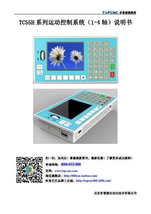
TC55H 系列运动控制系统(1-4轴)说明书北京多普康自动化技术有限公司扫一扫,加关注!掌握最新资讯,最新优惠!了解更多成功案例!咨询热线:4006-033-880官网:淘宝旗舰店:/阿里巴巴品牌工业城:/一、操作篇1.概述TC55H是北京多普康全新开发的新产品,可控制4个进给轴,1个模拟主轴,16路输入,8路输出,USB接口,支持U盘文件操作和程序运行,支持G代码编程。
1.1主要功能自动:自动加工运行,单段程序执行手动:手动高低速运行,手脉控制,当前选中轴程序回零,全部回程序零点,机械回零程序:编辑,读入,删除,另存,新建参数:控制参数,速度参数,输入参数,输出参数,厂值恢复USB:导入程序或开机图片密码:登陆用户,退出用户,修改密码外部手动:控制电机正反转,启动、暂停、报警、急停等程序指令:G指令和M指令隔离I/0口:带有与系统隔离的输入输出口模拟主轴输出:可接1路0~10V模拟主轴脉冲输出:4轴脉冲差分输出程序编辑:自动解释编辑指令1.2系统组成控制系统主要有以下部分组成● 3.5寸彩色液晶屏,分辨率320*240●触点按键阵列●4轴差分脉冲输出●输入/输出(16路光电隔离24V输入,8路光电隔离24V输出,单通道额定500mA)●1路模拟量主轴输出●1个面板型手轮,增量×1,×10,×100●1个USB接口,可插入U盘●最大程序行5000行,程序内存容量128M,可存100个加工程序1.3技术指标最小数据单位:0.001mm编程范围:±99999.999mm控制轴数:1~4轴(X,Y,Z,C)联动轴数:X,Y,Z,C轴可做直线插补,X,Y可做圆弧插补主轴数:1轴(S)各轴最大进给速度:9000mm/min(当脉冲当量为0.001mm时)插补:直线/圆弧电子齿轮:分子:1~99999,分母:1~999991.4尺寸z外形尺寸:长×宽×厚172×94×48mmz嵌入口尺寸:长×宽162×84mm,前面板厚4mm2.按键定义3.显示及操作方式3.1主界面系统上电后,跳过开机画面进入主界面,主界面显示坐标轴的位置,坐标的运行速度F及倍率,主轴的运行速度S及倍率,输入、输出口的状态。
Cpower-苏州度飞电气产品选型样本

变频器周边产品索引手册Exist ,only for quality!存在,只为品质!Suzhou Du Fei Electrical Co.,Ltd.度飞电气Braking UnitRipple ResistorWire-wound ResistorAluminum ResistorFilterReactorBraking Resistors boxPower Resistors unit制动单元波纹电阻器铝壳电阻器滤波器电抗器电阻箱电阻柜Inverter accessories为了您的高品质要求,我们精益求精!选择我们的理由:-你-质量-服务-性价比Reason for choosing us:-YOU -Quality -Ser vice-Cost performance +86(0512) 8219 1829/6766 6706 T:M:135****1508(深圳)186****3780/189****2858(苏州)¦▐ 01/02公司简介Company Profile是中国领先的变频器周边配件提供商,专注于研发、制造高品质的产品。
为行业用户、代理商和企业用户提供全面的变频器周边配件解决方案。
()筹备于2008年,公司总部位于江苏省苏州市,在深圳、北京、成都、上海等地设立或即将设立办事处,将进一步为当地客户提供及时周到的服务!任重而道远,望崦嵫而勿迫.公司期待实现良好的社会价值,成为行业的领航者!苏州度飞电气有限公司度飞电气Su Zhou Du Fei Electrical Co.,Ltd .企业核心价值观:使命:目标:精神:企业文化:提倡:务实、认真、敬业、创新为客户、为员工、为股东、为社会;为客户:度飛电气将提供信息技术、工具和服务;为社会:服务社会文明进步;为投资人:回报股东长远利益;为员工:创造发展空间,提升员工价值,提高工作生活质量。
做“Made in China”的典范,我们不追求数量的第一,只追求质量的前列!诚信、服务、奉献、分享、执行、合作、创新、专精尊重、快乐、激情、分享工作即是生活,享受工作,享受生活!▐ ►►►►►►►For your high quality requirements, We pursue and keep improving. +86(0512) 8219 1829/6766 6706 T:M:135****1508(深圳)186****3780/189****2858(苏州)¦▐▍铝壳电阻广泛应用于电源、变频器、伺服系统等高要求的电气回路中,并能使用于恶劣的工控环境¬¬主要用途 Main application¬¬▐03/04产品图片Product Image +86(0512) 8219 1829/6766 6706 T:M:135****1508(深圳)186****3780/189****2858(苏州)¦规格 Type specification电气性能 Electrical parametersPIC-APIC-B +86(0512) 8219 1829/6766 6706 T:M:135****1508(深圳)186****3780/189****2858(苏州)¦▍波纹绕线电阻广泛用于变频器制动,起重机械以及负载电阻之用。
TC125资料

General Description
The TC125/126 step-up (Boost) switching regulators furnish output currents to a maximum of 80mA (VIN = 2V, VOUT = 3V) with typical efficiencies above 80%. These devices employ pulse frequency modulation (PFM) for minimum supply current at low loads. They are ideal for battery-operated applications powered from one or more cells. Maximum supply current is less than 70µA at full output load, and less than 5µA in standby (VOUT = 3V). Both devices require only an external inductor, diode, and capacitor to implement a complete DC/DC regulator. The TC126 has separate output voltage sensing and chip power inputs for greater application flexibility. The TC125 combines the output voltage sensing and chip power inputs onto a single package pin, but adds a power-saving shutdown mode that suspends regulator operation and reduces supply current to less than 0.5µA when the shutdown control input (SHDN) is low. The TC125/TC126 are available in a small 5-Pin SOT-23A package, occupy minimum board space and use small external components. The TC125 accepts input voltages from 2V to 10V. The TC126 accepts input voltages from 2.2V to 10V. Both the TC125 and TC126 have a start-up voltage of 0.9V at light load.
MF_RC500_datasheet(中文)
2 3
4Leabharlann 55.2.3.1 页寄存器 ....................................................................................... 16 5.2.3.2 TxControl 寄存器 ........................................................................ 16 5.2.3.3 CwConductance 寄存器 ................................................................ 16 5.2.3.4 PreSet13 寄存器 .......................................................................... 17 5.2.3.5 PreSet14 寄存器 .......................................................................... 17 5.2.3.6 ModWidth 寄存器 .......................................................................... 17 5.2.3.7 PreSet16 寄存器 .......................................................................... 17 5.2.3.8 PreSet17 寄存器 .......................................................................
赛米控丹佛斯电子 SEMiX854GB176HDs 数据表

SEMiX ®4sTrench IGBT ModulesSEMiX854GB176HDsFeatures•Homogeneous Si•Trench = Trenchgate technology •V CE(sat) with positive temperature coefficient•UL recognised file no. E63532Typical Applications*•AC inverter drives •UPS•Electronic weldersAbsolute Maximum Ratings SymbolConditions Values UnitIGBT V CES T j =25°C 1700V I C T j =150°CT c =25°C 779A T c =80°C549A I Cnom 600A I CRMI CRM = 2xI Cnom 1200A V GES -20...20V t psc V CC =1000V V GE ≤ 20V V CES ≤ 1700VT j =125°C10µs T j-55...150°C Inverse diode I F T j =150°CT c =25°C 740A T c =80°C 496A I Fnom600A I FRM I FRM = 2xI Fnom1200A I FSM t p =10ms, sin 180°, T j =25°C3800A T j -40 (150)°C Module I t(RMS)T terminal =80°C600A T stg -40...125°C V isolAC sinus 50Hz, t =1min4000VCharacteristics SymbolConditions min.typ.max.UnitIGBT V CE(sat)I C =600A V GE =15V chiplevelT j =25°C 2 2.45V T j =125°C 2.5 2.9V V CE0T j =25°C 1 1.2V T j =125°C0.9 1.1V r CE V GE =15VT j =25°C 1.7 2.1m ΩT j =125°C2.63.0m ΩV GE(th)V GE =V CE , I C =24mA 5.25.86.4V I CES V GE =0V V CE =1700V T j =25°C 4mA T j =125°C mA C ies V CE =25V V GE =0Vf =1MHz 52.8nF C oes f =1MHz 2.20nF C res f =1MHz1.75nF Q G V GE =- 8 V...+ 15 V 5600nC R Gint T j =25°C 1.25Ωt d(on)V CC =1200V I C =600A V GE =±15V R G on =2ΩR G off =2ΩT j =125°C 340ns t r T j =125°C 80ns E on T j =125°C 300mJ t d(off)T j =125°C 890ns t f T j =125°C 155ns E off T j =125°C250mJ R th(j-c)per IGBT 0.045K/WCharacteristics SymbolConditionsmin.typ.max.UnitInverse diodeV F = V EC I F =600AV GE =0V chipT j =25°C 1.7 1.90V T j =125°C 1.7 1.9V V F0T j =25°C 0.9 1.1 1.3V T j =125°C0.70.9 1.1V r FT j =25°C 1.0 1.0 1.0m ΩT j =125°C1.31.3 1.3m ΩI RRM I F =600A di/dt off =8000A/µs V GE =-15VV CC =1200VT j =125°C 730A Q rr T j=125°C220µC E rr T j =125°C 170mJR th(j-c)per diode0.081K/WModule L CE 22nH R CC'+EE'res., terminal-chip T C =25°C 0.7m ΩT C =125°C1m ΩR th(c-s)per module 0.03K/W M s to heat sink (M5)35Nm M tto terminals (M6)2.55Nm Nmw400gTemperatur Sensor R 100T c =100°C (R 25=5 k Ω)493 ± 5%ΩB 100/125R (T)=R 100exp[B 100/125(1/T-1/T 100)]; T[K];3550 ±2%K SEMiX ® 4sTrench IGBT ModulesSEMiX854GB176HDsFeatures•Homogeneous Si•Trench = Trenchgate technology •V CE(sat) with positive temperature coefficient•UL recognised file no. E63532Typical Applications*•AC inverter drives •UPS•Electronic weldersFig. 1: Typ. output characteristic, inclusive R CC'+ EE'Fig. 2: Rated current vs. temperature I C = f (T C )Fig. 3: Typ. turn-on /-off energy = f (I C )Fig. 4: Typ. turn-on /-off energy = f (R G )Fig. 5: Typ. transfer characteristic Fig. 6: Typ. gate charge characteristicFig. 7: Typ. switching times vs. I C Fig. 8: Typ. switching times vs. gate resistor R GFig. 9: Typ. transient thermal impedance Fig. 10: Typ. CAL diode forward charact., incl. R CC'+EE'Fig. 11: Typ. CAL diode peak reverse recovery current Fig. 12: Typ. CAL diode recovery chargeThis is an electrostatic discharge sensitive device (ESDS), international standard IEC 60747-1, Chapter IX* The specifications of our components may not be considered as an assurance of component characteristics. Components have to be tested for the respective application. Adjustments may be necessary. The use of SEMIKRON products in life support appliances and systems is subject to prior specification and written approval by SEMIKRON. We therefore strongly recommend prior consultation of our staff.spring configuration。
欧姆龙RFID
RFID㋏㒳
V680㋏߫
ᷛㅒgᬒ఼᪡ݠ (FRAMൟ)
ᬒ఼g㒓 V680-HA63B V680-HS52 V680-HS63 V680-HS65
IDᷛㅒ V680-D2KF52M V680-D2KF67 V680-D2KF67M V680-D8KF68 V680-D32KF68
Undertegnede Omron erklærer herved, at følgende den RFID System, V680-HS52 Serie, V680-HS63 Serie, V680-HS65 Serie, 680-HA63B Serie overholder de væsentlige krav og øvrige relevante krav i direktiv 1999/5/EF.
RFID 系统
2
操作手册
前言
前言 ⑥请务必遵守各项使用事项和使用禁止事项,避免发生不正确使用以及由此对客户本身及第三者造成的损
害。
4.设计·规格的变更
本产品目录中记载的各项产品、附属品的设计·规格,由于各种原因,可能会根据需要进行变更,购买时请 与销售网点的人员确认实际的设计·规格。
5.服务范围
本公司产品价格中不包含技术人员派遣等服务费用。 如客户需要提供相关技术服务,可与销售网点的人员联系。
2.责任免除
①在任何情况下,对包括因本公司产品引起的特别损失、间接损失在内的一切损失本公司均不承责任。 ②使用可编程设备时,非因本公司人员进行的编程引起的全部后果,本公司不承担任何责任。
3.适合用途、条件
①本产品并不是出于维护安全目而设计的用于直接或间接探测人类的存在的产品。相关用途请使用本公司传 感器样本中记载的安全传感器。
海利普变频器说明书C100

围。
HLP-C100 系列使用说明书
系列
危险
● 变频器运转中严禁将电机机组投入或切离,否则会造成变频器 过电流跳脱,甚至烧毁变频器主回路。
72
10.1 故障列表
72
10.2 操作异常及处理
73
第11章 日常维护
75
11.1 注意事项
75
11.2 变频器存储和运输
75
第12章 通讯协议
76
12.1 格式说明
76
12.2 线圈寄存器编址
76
12.3 读线圈状态
78
12.4 读保持寄存器
79
12.5 写单个线圈状态
79
12.6 写单个保持寄存器值 12.7 写多个线圈状态 12.8 写多个保持寄存器 12.9 读写数组参数 12.10 通信错误代码
系列
1 1 2 2 3 4 4 5 5 8 8 8 8 9 9 9 9 11 13 14 14 14 15 16 18 19 20 21 21 21 21
系列
5.4 正反转、点动
21
5.5 多段速
22
5.6 故障复位
23
第6章 功能参数表
24
第7章 参数详细说明
34
7.1 第00组参数:操作/显示
34
7.2 第01组参数:负载/电动机
36
7.3 第02组参数:制动功能
40
7.4 第03组参数:设定值/加减速
41
7.5 第04组参数:极限/警告设置
TC55说明书(新)
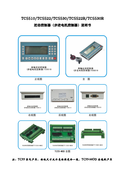
TC5510/TC5522/TC5530/TC5522R/TC5530R运动控制器(步进电机控制器)说明书正视图 全 图右视图 后视图 右视图TC55-MOD全图注:TC55系列产品,面板尺寸及外壳面膜完全一致,TC55-MOD为选配产品一、概述篇TC55面板型运动控制器(数控系统)采用高性能32位CPU,驱动装置采用细分步进电机或交流伺服电机,配备液晶显示器,全封闭触摸式操作键盘。
该系统具有可靠性高,精度高,噪音小,操作方便等特点。
本控制器可控制1-3个电机运动,可实现点位、直线插补、圆弧插补的操作。
具有循环、跳转及简易PLC等功能。
简单、清晰的参数带给您方便和快捷的操作。
输入/输出的设置功能可方便您的使用和维修,适用于各类的1-3轴运动装置。
产品特点开机画面可自行修改 控制器或上位计算机双模式编程独立24V电源反接保护 IO光耦隔离 输出短接保护 手动正反转可同步外部开关控制 简易PLC逻辑 参数密码可设定适用产品类型●数控钻床系统、数控车床系统、数控铣床系统、数控磨床系统●裁剪机控制系统、切割机控制系统、焊接控制系统、点胶机控制系统、送料控制系统●位移台、一维控制平台、二维控制平台、三维控制平台●螺纹机控制系统、锁螺丝机控制系统●喷涂生产线控制系统、装配生产线控制系统、记米器控制系统技术特点●自动执行:可实现实际运行、空运行、单段执行、终止程序、 启动和暂停功能●手动操作:可实现手动高、低速、点动操作、回程序零、回机械零等操作。
●程序管理:可实现对程序进行编辑、读入、删除、保存功能。
●参数设置:可设置与加工、操作有关的各个控制参数,使加工效果达到最佳状态。
系统参数●高性能、高速度32位●高档黑白双色液晶显示器(分辨率:192×64)●专用运动控制芯片(信号输出为:5V TTL)●通用可自定义输入/输出(16路光电隔离24V输入,8路继电器输出)●用户加工程序存储器(可存储20个程序)●最小数据单位 0.001mm●最大数据尺寸 ±99999.999mm●最高脉冲输出频率 150KHz●系统主要功能 自动、手动、程序编辑、系统参数、自检、设置等安装形式●面板型安装结构。
信号转换器TV500L-100-5

信号转换器TV500L-100-5Isolating Signal Converter TV 500L信号隔离器TV 500LUnipolar or bipolar in- and outputs单极或双极-输出Features特征M Switch-selectable inputs可选输入0/4...20mA and 0/2 (10V)or -20 ... 20mA and -10 (10V)M Switch-selectable outputs可选输出0/4...20mA and 0/2 (10V)or -20 ... 20; and -10 (10V)M Increasing or decreasing output characteristic增加或减少输出特点M Supply voltage 电源电压230V AC or 24V DCM Full 3-port isolation端口隔离M Power-on LED功率指示M 22.5mm case for DIN rail mounting导轨安装M UL-CSA-standard on requestUL-CSA标准要求General概括Isolating signal converter TV500L can be used to isolate and convert unipolar or bipolar field signals into indus-try standard unipolar 0/4 ... 20 mA and 0/2 ... 10 V DC or bipolar signals for process control systems.信号分离转换器TV500L可用于分离和转换单极或双极场信号,将该信号转换成0-20mA或0-10v的信号,用于控制系统。
Short information短信息Current output电流输出Multi-range多范围Current output is provided by a link between terminal 8 and 9max. burden 500 Ω. 8和9为电流输出端,最大负担为500Ω。
