SMDA05C-4中文资料
SMT贴片

B:来料检测 => PCB的A面插件(引脚打弯)=>翻板 => PCB的B面点贴片胶 =>贴片 =>固化 =>翻板 =>波 峰焊 =>清洗 =>检测 =>返修
先插后贴,适用于分离元件多于SMD元件的情况
C:来料检测 => PCB的A面丝印焊膏 =>贴片 =>烘干 =>回流焊接 =>插件,引脚打弯 =>翻板 => PCB的B面 点贴片胶 =>贴片 =>固化 =>翻板 =>波峰焊 =>清洗 =>检测 =>返修A面混装,B面贴装。
薄膜印刷线路
薄膜印刷线路
薄膜印刷线路SMT贴片(2张)此类薄膜线路一般是用银浆在PET上印刷线路。在此类薄膜线路上粘贴黏贴电子 元器件有两种工艺工法,一种谓之传统工艺工法即3胶法(红胶、银胶、包封胶)或2胶法(银胶、包封胶),另一 种谓之新工艺即1胶法---顾名思义,就是用一种胶即可完成粘贴黏贴电子元器件,而不再用3种胶或2种胶。此新 工艺关键是使用一种新型导电胶,完全具有锡膏的导电性能和工艺性能;使用时完全兼容现行的SMT刷锡膏作业 法,毋需添加任何设备。
单面混装工艺
来料检测 => PCB的A面丝印焊膏(点贴片胶)=>贴片 =>烘干(固化)=>回流焊接 =>清洗 =>插件 =>波峰 焊 =>清洗 =>检测 =>返修
双面混装工艺
A:来料检测 =>PCB的B面点贴片胶 =>贴片 =>固化 =>翻板 => PCB的A面插件=>波峰焊 =>清洗 =>检测 =>返修
华汕电子 1020晶体管芯片说明书

PNP S I L I C O N T R A N S I S T O R
1020 晶体管芯片说明书
█ 芯片简介
█ 管芯示意图
芯片尺寸:4 英寸(100mm)
芯片代码:A075AJ-00
芯片厚度:240±20µm
管芯尺寸:750×750µm 2
焊位尺寸:B 极 165×170µm2;E 极 150×165µm2
集电极— 发射极饱和电压 基极— 发射极饱和电压 特征频率 共基极输出电容
最小值 典型值 最大值 单位
测试条件
-50
V IC=-100µA ,IE=0
-50
V IC=-10mA,IB=0
-5
V IE=-100µA ,IC=0
-1
µA VCB=-50V,IE=0
-1
µA VEB=-5V,IC=0
70
240
█ 电参数(Ta=25℃)CEO BVEBO ICBO IEBO hFE
VCE(sat) VBE(sat) fT Cob
符号说明 集电极— 基极击穿电压 集电极— 发射极击穿电压 发射极— 基极击穿电压 集电极— 基极截止电流 发射极— 基极截止电流 直流电流增益
电极金属:铝
背面金属:金
典型封装:2SA1020
█ 极限值(Ta=25℃)(TO-92L)
Tstg——贮存温度………………………………… -55~150℃ Tj——结温…………………………………………… 150℃ PC——集电极功率耗散( Ta=25℃)…………………900mW VCBO——集电极—基极电压……………………………-50V VCEO——集电极—发射极电压…………… ……………- 50 V VEBO —— 发射极— 基极电压…………………… ………-5 V IC——集电极电流………………………………………-2A IB——基极电流…………………………………………-0.5A
C12935资料

For a complete identification, please use the following items : 10 1 Series BS style Contact type Termination type Number of contacts Variant
retaining strap
Dimensions in mm For availability please consult us.
Nber of contacts Single row Nber of contacts Two rows
02 03 04 05 06 07 08 09 10 11 12 13 14 15 16 17 18 19 20 21 22 23 24 25 04 06 08 10 12 14 16 18 20 22 24 26 28 30 32 34 36 38 40 42 44 46 48 50 7,6 9,6 11,6 13,6 15,6 17,6 19,6 21,6 23,6 25,6 27,6 29,6 31,6 33,6 35,6 37,6 39,6 41,6 43,6 45,6 47,6 49,6 51,6 53,6
APPROVALS
s s s s Complies with MIL. C 55302 and BS 9525-F0033 ISO 9002 n° 353 658 OTAN F8378 GAM T1
3
元器件交易网
Micro-connector CMM 100/200 series
4.75
2
3.2
5.5
0.5
L
1 6 0.8 A
SMDA资料

DESCRIPTION (300 and 500 watt)This 8 pin 4 line Unidirectional or Bidirectional array is designed for use in applications where protection is required at the board level from voltage transients caused by electrostatic discharge (ESD) as defined by IEC 1000-4-2, electrical fast transients (EFT) per IEC 1000-4-4 and effects of secondary lighting.These arrays are used to protect any combination of 4 lines. The SMDA/B product provides board level protection from static electricity and other induced voltage surges that can damage sensitive circuitry.These TRANSIENT VOLTAGE SUPPRESSOR (TVS) Diode Arrays protect 3.0/3.3Volt components such as DRAM’s, SRAM’s, CMOS, HCMOS, HSIC, and low voltage interfaces up to 24Volts.FEATURESMECHANICAL• Protects 3.0/3.3 up through 24V Components •Molded SO-8 Surface Mount• Protects 4 lines Unidirectional or Bidirectional •Weight: 0.066 grams (approximate)• Provides electrically isolated protection •Body Marked with Logo, and device number •SO-8 Packaging•Pin #1 defined by DOT on top of packageMAXIMUM RATINGS PACKAGING• Operating Temperatures: -550C to +1500C •Tape & Reel EIA Standard 481-1-A • Storage Temperature: -550C to +1500C•13 inch reel 2,500 pieces (OPTIONAL)• SMDA Peak Pulse Power: 300 Watts (8/20 µsec, Figure 1)•Carrier tubes 95 pcs per (STANDARD)• SMDB Peak Pulse Power: 500 Watts (8/20 µsec, Figure 1)•Pulse Repetition Rate: <.01%0Part numbers with a “C” suffix are bidirectional devicesSMDA/B03THRU SMDA/B24CTVSarray ™ Seriesomp onents 21201 Itasca Street Chatsworth! "# $ % ! "#NOTE: Transient Voltage Suppression (TVS) product is normally selected based on its stand off Voltage V WM . Product selected voltage should be equal to or greater than the continuous peak operating voltage of the circuit to be protected.WAVE FORMSFIGURE 2Peak Pulse Power Vs Pulse Time Pulse Wave FormSM DA/B 03 t hru SM DA/B 24C。
SMDA15CM中文资料

SMDA05CMthruSMDA24CMST ANDARD CAP ACIT ANCE TVS ARRA YOnly One Name Means ProTek’Tion™APPLICA TIONS✔ RS-232, RS-422 & RS-423 Data Lines✔ Microprocessor Based Equipment ✔ Control & Monitoring Equipment ✔ Modems✔ Portable Electronics ✔ Medical ElectronicsIEC COMP A TIBILITY (EN61000-4)✔ 61000-4-2 (ESD): Air - 15kV , Contact - 8kV ✔ 61000-4-4 (EFT): 40A - 5/50ns✔ 61000-4-5 (Surge): 12A, 8/20µs - Level 1(Line-Gnd) & Level 2(Line-Line)FEA TURES✔ 500 Watts Peak Pulse Power per Line (tp=8/20µs)✔ Bidirectional Configurations ✔ Monolithic Design✔ Available in Voltage Types Ranging From: 5V to 24V ✔ Protects 4 - 7 Lines✔ ESD Protection > 40 kilovolts✔ RoHS Compliant in Lead-Free VersionsMECHANICAL CHARACTERISTICS✔ Molded JEDEC SO-8 Package✔ Weight 70 milligrams (Approximate)✔ Available in Tin-Lead or Lead-Free Pure-Tin Plating(Annealed)✔ Solder Reflow Temperature:Tin-Lead - Sn/Pb, 85/15: 240-245°C Pure-Tin - Sn, 100: 260-270°C✔ Flammability rating UL 94V-0✔ 12mm T ape and Reel Per EIA Standard 481✔ Marking: Logo, Marking Code, Date Code & Pin One Defined By Dot on Top of Package05070PIN CONFIGURATIONSO-8SMDA05CMthruSMDA24CMDEVICE CHARACTERISTICSMAXIMUM RA TINGS @ 25°C Unless Otherwise SpecifiedOperating T emperature SYMBOL VALUE -55°C to 150°C°C°C -55°C to 150°C UNITS T J T STGPARAMETERStorage T emperaturePeak Pulse Power (t p = 8/20µs) - See Figure 1P PP 500Watts ELECTRICAL CHARACTERISTICS PER LINE @ 25°C Unless Otherwise SpecifiedPART NUMBERDEVICE MARKING CODEMINIMUM BREAKDOWN VOLTAGE@ 1mA V (BR)VOLTS MAXIMUM CLAMPING VOLTAGE (See Fig. 2)@ I P = 1AV C VOLTS MAXIMUM CLAMPING VOLTAGE (See Fig. 2)@8/20µs V C @ I PP MAXIMUM CAPACITANCE PER LINE@0V , 1 MHzC pFSMDA05CM SMDA08CM SMDA12CM SMDA15CM SMDA24CMREB REC RED REF REH6.08.513.416.726.79.813.419.024.043.019.0V @ 30A 23.7V @ 24A 29.2V @ 20A 31.1V @ 18A 45.0V @ 13A35030015010063MAXIMUM LEAKAGE CURRENT@V WMI D µA 10010111RATED STAND-OFF VOLTAGEV WM VOLTS5.08.012.015.024.0SMDA05CMthruSMDA24CMGRAPHST L - Lead T emperature - °C20406080100% O f R a t e d P o w e rFIGU RE 30 5 10 15 20 25 30t - Time - µs20406080100120I P P - P e a k P u l s e C u r r e n t -% o f I P PFIGU RE 20.1 1 10 100 1,000 10,000t d - Pulse Duration - µs101001,00010,000P P P - P e a k P u l s e P o w e r - W a t t sFIGU RE 1PEAK PULSE POWER VS PULSE TIMESMDA05CMthruSMDA24CMCOPYRIGHT © ProTek Devices 2005SPECIFICATIONS: ProTek reserves the right to change the electrical and or mechanical characteristics described herein without notice (except JEDEC).DESIGN CHANGES: ProTek reserves the right to discontinue product lines without notice, and that the final judgement concerning selection and specifications is the buyer’s and that in furnishing engineering and technical assistance, ProTek assumes no responsibility with respect to the selection or specifications of such products.P ACKAGE OUTLINE & DIMENSIONSProTek Devices2929 South Fair Lane, Tempe, AZ 85282Tel: 602-431-8101 Fax: 602-431-2288E-Mail: sales@ Web Site: 。
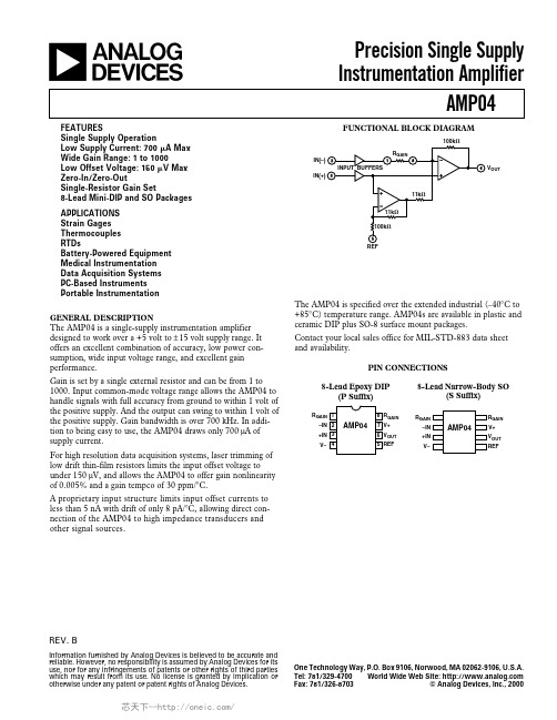
AMP04FSZ,AMP04FPZ,AMP04EPZ,AMP04FSZ-RL,AMP04FSZ-R7,AMP04FS-REEL7,AMP04ESZ-R7, 规格书,Datasheet 资料
One Technology Way, P.O. Box 9106, Norwood, MA 02062-9106, U.S.A.
Tel: 781/329-4700 World Wide Web Site:
Fax: 781/326-8703
© Analog Devices, Inc., 2000
For high resolution data acquisition systems, laser trimming of low drift thin-film resistors limits the input offset voltage to under 150 µV, and allows the AMP04 to offer gain nonlinearity of 0.005% and a gain tempco of 30 ppm/°C.
1000 1 0.005 0.015 0.025 30
0.75 %
1.0 %
0.75
%
1000 V/V
%
%
%
50
ppm/°C
OUTPUT Output Voltage Swing High
Output Voltage Swing Low Output Current Limit
VOH
RL = 2 kΩ
Contact your local sales office for MIL-STD-883 data sheet and availability.
PIN CONNECTIONS
8-Lead Epoxy DIP (P Suffix)
8-Lead Narrow-Body SO (S Suffix)
25
Altium_designer常用库中文解说
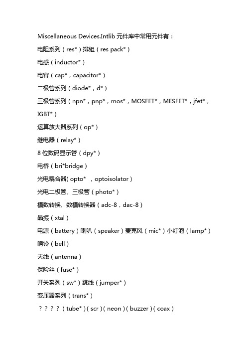
Miscellaneous Devices.Intlib元件库中常用元件有:电阻系列(res*)排组(res pack*)电感(inductor*)电容(cap*,capacitor*)二极管系列(diode*,d*)三极管系列(npn*,pnp*,mos*,MOSFET*,MESFET*,jfet*,IGBT*)运算放大器系列(op*)继电器(relay*)8位数码显示管(dpy*)电桥(bri*bridge)光电耦合器( opto* ,optoisolator )光电二极管、三极管(photo*)模数转换、数模转换器(adc-8,dac-8)晶振(xtal)电源(battery)喇叭(speaker)麦克风(mic*)小灯泡(lamp*)响铃(bell)天线(antenna)保险丝(fuse*)开关系列(sw*)跳线(jumper*)变压器系列(trans*)????(tube*)(scr)(neon)(buzzer)(coax)晶振(crystal oscillator)的元件库名称是Miscellaneous Devices.Intlib, 在search栏中输入*soc 即可。
########### DXP2004下Miscellaneous connectors.Intlib元件库中常用元件有:(con*,connector*)(header*)(MHDR*)定时器NE555P 在库TI analog timer circit.Intlib中电阻AXIAL无极性电容RAD电解电容RB-电位器VR二极管DIODE三极管TO电源稳压块78和79系列TO-126H和TO-126V场效应管和三极管一样整流桥D-44 D-37 D-46单排多针插座CON SIP双列直插元件DIP晶振XTAL1电阻:RES1,RES2,RES3,RES4;封装属性为axial系列无极性电容:cap;封装属性为RAD-0.1到rad-0.4电解电容:electroi;封装属性为rb.2/.4到rb.5/1.0电位器:pot1,pot2;封装属性为vr-1到vr-5二极管:封装属性为diode-0.4(小功率)diode-0.7(大功率)三极管:常见的封装属性为to-18(普通三极管)to-22(大功率三极管)to-3(大功率达林顿管)电源稳压块有78和79系列;78系列如7805,7812,7820等79系列有7905,7912,7920等常见的封装属性有to126h和to126v整流桥:BRIDGE1,BRIDGE2: 封装属性为D系列(D-44,D-37,D-46) 电阻: AXIAL0.3-AXIAL0.7 其中0.4-0.7指电阻的长度,一般用AXIAL0.4瓷片电容:RAD0.1-RAD0.3. 其中0.1-0.3指电容大小,一般用RAD0.1电解电容:RB.1/.2-RB.4/.8 其中.1/.2-.4/.8指电容大小.一般<100uF 用RB.1/.2,100uF-470uF用RB.2/.4,>470uF用RB.3/.6二极管: DIODE0.4-DIODE0.7 其中0.4-0.7指二极管长短,一般用DIODE0.4发光二极管:RB.1/.2集成块: DIP8-DIP40, 其中8-40指有多少脚,8脚的就是DIP8贴片电阻0603表示的是封装尺寸与具体阻值没有关系但封装尺寸与功率有关通常来说0201 1/20W0402 1/16W0603 1/10W0805 1/8W1206 1/4W电容电阻外形尺寸与封装的对应关系是:0402=1.0x0.50603=1.6x0.80805=2.0x1.21206=3.2x1.61210=3.2x2.51812=4.5x3.22225=5.6x6.5关于零件封装我们在前面说过,除了DEVICE.LIB库中的元件外,其它库的元件都已经有了固定的元件封装,这是因为这个库中的元件都有多种形式:以晶体管为例说明一下:晶体管是我们常用的的元件之一,在DEVICE.LIB库中,简简单单的只有NPN与PNP之分,但实际上,如果它是NPN的2N3055那它有可能是铁壳子的TO—3,如果它是NPN的2N3054,则有可能是铁壳的TO-66或TO-5,而学用的CS9013,有TO-92A,TO-92B,还有TO-5,TO-46,TO-52等等,千变万化.还有一个就是电阻,在DEVICE库中,它也是简单地把它们称为RES1和RES2,不管它是100Ω还是470KΩ都一样,对电路板而言,它与欧姆数根本不相关,完全是按该电阻的功率数来决定的我们选用的1/4W和甚至1/2W的电阻,都可以用AXIAL0.3元件封装,而功率数大一点的话,可用AXIAL0.4,AXIAL0.5等等.现将常用的元件封装整理如下:电阻类及无极性双端元件AXIAL0.3-AXIAL1.0无极性电容RAD0.1-RAD0.4有极性电容RB.2/.4-RB.5/1.0二极管DIODE0.4及DIODE0.7石英晶体振荡器XTAL1晶体管、FET、UJT TO-xxx(TO-3,TO-5)可变电阻(POT1、POT2) VR1-VR5当然,我们也可以打开C:\Client98\PCB98\library\advpcb.lib库来查找所用零件的对应封装.这些常用的元件封装,大家最好能把它背下来,这些元件封装,大家可以把它拆分成两部分来记如电阻AXIAL0.3可拆成AXIAL和0.3,AXIAL翻译成中文就是轴状的,0.3则是该电阻在印刷电路板上的焊盘间的距离也就是300mil(因为在电机领域里,是以英制单位为主的.同样的,对于无极性的电容,RAD0.1-RAD0.4也是一样;对有极性的电容如电解电容,其封装为RB.2/.4,RB.3/.6等,其中“.2”为焊盘间距,“.4”为电容圆筒的外径. 对于晶体管,那就直接看它的外形及功率,大功率的晶体管,就用TO—3,中功率的晶体管,如果是扁平的,就用TO-220,如果是金属壳的,就用TO-66,小功率的晶体管,就用TO-5,TO-46,TO-92A等都可以,反正它的管脚也长,弯一下也可以.对于常用的集成IC电路,有DIPxx,就是双列直插的元件封装,DIP8就是双排,每排有4个引脚,两排间距离是300mil,焊盘间的距离是100mil.SIPxx就是单排的封装.等等.值得我们注意的是晶体管与可变电阻,它们的包装才是最令人头痛的,同样的包装,其管脚可不一定一样.例如,对于TO-92B之类的包装,通常是1脚为E(发射极),而2脚有可能是B极(基极),也可能是C(集电极);同样的,3脚有可能是C,也有可能是B,具体是那个,只有拿到了元件才能确定.因此,电路软件不敢硬性定义焊盘名称(管脚名称),同样的,场效应管,MOS管也可以用跟晶体管一样的封装,它可以通用于三个引脚的元件.Q1-B,在PCB里,加载这种网络表的时候,就会找不到节点(对不上). 在可变电阻上也同样会出现类似的问题;在原理图中,可变电阻的管脚分别为1、W、及2,所产生的网络表,就是1、2和W,在PCB电路板中,焊盘就是1,2,3.当电路中有这两种元件时,就要修改PCB与SCH之间的差异最快的方法是在产生网络表后,直接在网络表中,将晶体管管脚改为1,2,3;将可变电阻的改成与电路板元件外形一样的1,2,3即可.PCB元件封装库命名规则1、集成电路(直插)用DIP-引脚数量+尾缀来表示双列直插封装尾缀有N和W两种,用来表示器件的体宽N为体窄的封装,体宽300mil,引脚间距2.54mmW为体宽的封装, 体宽600mil,引脚间距2.54mm如:DIP-16N表示的是体宽300mil,引脚间距2.54mm的16引脚窄体双列直插封装2 、集成电路(贴片)用SO-引脚数量+尾缀表示小外形贴片封装尾缀有N、M和W三种,用来表示器件的体宽N为体窄的封装,体宽150mil,引脚间距1.27mmM为介于N和W之间的封装,体宽208mil,引脚间距1.27m mW为体宽的封装, 体宽300mil,引脚间距1.27mm如:SO-16N表示的是体宽150mil,引脚间距1.27mm的16引脚的小外形贴片封装若SO前面跟M则表示为微形封装,体宽118mil,引脚间距0. 65mm3、电阻3.1 SMD贴片电阻命名方法为:封装+R如:1812R表示封装大小为1812的电阻封装3.2 碳膜电阻命名方法为:R-封装如:R-AXIAL0.6表示焊盘间距为0.6英寸的电阻封装3.3 水泥电阻命名方法为:R-型号如:R-SQP5W表示功率为5W的水泥电阻封装4、电容4.1 无极性电容和钽电容命名方法为:封装+C如:6032C表示封装为6032的电容封装4.2 SMT独石电容命名方法为:RAD+引脚间距如:RAD0.2表示的是引脚间距为200mil的SMT独石电容封装4.3 电解电容命名方法为:RB+引脚间距/外径如:RB.2/.4表示引脚间距为200mil, 外径为400mil的电解电容封装5、二极管整流器件命名方法按照元件实际封装,其中BAT54和1N4148封装为1 N41486 、晶体管命名方法按照元件实际封装,其中SOT-23Q封装的加了Q以区别集成电路的SOT-23封装,另外几个场效应管为了调用元件不致出错用元件名作为封装名7、晶振HC-49S,HC-49U为表贴封装,AT26,AT38为圆柱封装,数字表规格尺寸如:AT26表示外径为2mm,长度为8mm的圆柱封装8、电感、变压器件电感封封装采用TDK公司封装9、光电器件9.1 贴片发光二极管命名方法为封装+D来表示如:0805D表示封装为0805的发光二极管9.2 直插发光二极管表示为LED-外径如LED-5表示外径为5mm的直插发光二极管9.3 数码管使用器件自有名称命名10、接插10.1 SIP+针脚数目+针脚间距来表示单排插针,引脚间距为两种:2mm,2.54mm如:SIP7-2.54表示针脚间距为2.54mm的7针脚单排插针10.2 DIP+针脚数目+针脚间距来表示双排插针,引脚间距为两种:2mm,2.54mm如:DIP10-2.54表示针脚间距为2.54mm的10针脚双排插针10.3 其他接插件均按E3命名Altium Designer 快捷键1. PCB设计快捷键(单次按键)单次按键是指按下该键并放开。
SMD-NTC整体规格书

H
±3%
J
±5%
K
±10%
⑧
T
包装 Packing 编带 Tape & Reel
F
T
F
⑦
⑧
⑨
③
内部代号 Internal Code
X
⑥
B 常数 B Constant (25-50℃)
Example Nominal Value
3380
3380K
4250
4250K
⑨
无有害物质产品 Hazardous Substance
NTC1608X332 □3950◎TF 3.3
NTC1608X472 □3950◎TF 4.7
NTC1608X502 □3950◎TF 5.0
NTC1608X682 □3950◎TF 6.8
NTC1608X103 □3450◎TF
10
NTC1608X103 □3950◎TF
10
NTC1608X153 □3950◎TF
Power
热时间常数 耗散因子 额定功率
sec
mW/℃
mW
t
C
P
<5sec
1.0
100
规格特性
SPECIFICATIONS
NTC1608 TYPE
Part Number 型号
Resistance B constant
at 25℃ (25-50℃)
电阻
B 常数
Units 单位
kΩ
Symbol 符号
R25
用途
● 移动电话,汽车电话,无绳电话等通讯设备
● 打印机,传真机,文字处理机等办公设备 ● 录像机,DVD, CD 等消费类电子设备
SMD零件计数器产品说明书(中英文介绍)

SMD零件计数器(YC-812 YC-812型)目录:1、产品介绍———————————————2、产品注意事项————————————3、产品的安装与说明———————————4、功能键的说明—————————————5、建议故障的排除————————————6、测漏功能———————————————第一章产品介绍The first chapter product introduction全自动SMD零件计数器,两种型号:普通零件计数器和测漏型零件计数器。
Completely automatic SMD components counter, two kind of models: Ordinary components counter and leak hunting components counter.一、产品原理Product principle1、普通零件计数器:采用光电传感原理,利用零件载带引导孔与零件的对应关系,通过专用处理芯片及大规模集成电路处理,实现零误差,精确测定SMD 零件计数量,可实现方便快捷的计数,是SMT物料管理的高效辅助设备。
Ordinary components counter: Uses the electro-optical sensing principle, carries using the components leads the pilot hole and the components corresponding relationships, through the special-purpose processing chip and large scale integrated circuit processing, realizes the zero error, the accurate determination SMD components counting quantity, may realize the convenience quick counting, is the SMT material management highly effective supporting facility.2、测漏型零件计数器:配备高速光纤,根据空料和实料光线强度对比原理,准确检知空料。
SFC05-4_04中文资料

2004 Semtech Corp.
4
元器件交易网
PROTECTION PRODUCTS Applications Information
Device Connection Options
The SFC05-4 has solder bumps located in a 3 x 2 matrix layout on the active side of the device. The bumps are designated by the numbers 1 - 3 along the horizontal axis and letters A - B along the vertical axis. The lines to be protected are connected at bumps A1, B1, A3, and B3. Bumps A2 and B2 are connected to ground. All path lengths should be kept as short as possible to minimize the effects of parasitic inductance in the board traces.
Flip Chip TVS
Flip chip TVS devices are wafer level chip scale packages. They eliminate external plastic packages and leads and thus result in a significant board space savings. Manufacturing costs are minimized since they do not require an intermediate level interconnect or interposer layer for reliable operation. Their compatibility with current pick and place equipment further reduces manufacturing costs. Certain precautions and design considerations have to be observed, however, for maximum solder joint reliability. These include solder pad definition, board finish, and assembly parameters.
日本白光HAKKO主机型号大全
锡线 HEXSOL FS300-01 FS400-01 FS400-02 FS401-01 FS401-02
锡线 HEXSOL FS402-01 FS402-02 FS402-03 FS402-04
化学助焊膏 PASTE(FS-120) FS120-01 FS120-02
助焊剂 001 001-01 001-02 001-03 001-04
助焊剂 CHEMICAL 1
助焊剂 SUSSOL-F 89-031 89-100 89-400 89
锡线 HEXSOL FS500-01 FS501-01 FS501-02 FS501-03 FS600-01 FS600-02 FS600-03 FS600-04
化学膏 FS-100 FS-100
焊咀清洁器 FT-700 FT700-01
电热剥线钳 FT-801 FT801-01
切割机电动装备 152B 152B
电阻切割成形机 153 153-1
电阻切割成形机 154 154-1
电阻切割机 155 155-1 155-2
精钢电子工具剪钳 106-01~08 106-01 106-02 106-03 106-04 106-05 106-06 106-07 106-08
自动出锡焊铁 958 958-01 958-02
自动出锡焊铁 959 959-01 959-02
电烙铁 FX-600 FX600-01 FX600-02
电烙铁 FX-601 FX601-01 FX601-03
定温烙铁 DASH N452 N453 N454 N452E N453E N454E
半导体器件芯片常用型号参数12页word文档
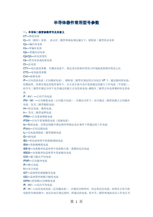
半导体器件常用型号参数一、半导体二极管参数符号及其意义CT---势垒电容Cj---结(极间)电容,表示在二极管两端加规定偏压下,锗检波二极管的总电容Cjv---偏压结电容Co---零偏压电容Cjo---零偏压结电容Cjo/Cjn---结电容变化Cs---管壳电容或封装电容Ct---总电容CTV---电压温度系数。
在测试电流下,稳定电压的相对变化与环境温度的绝对变化之比CTC---电容温度系数Cvn---标称电容IF---正向直流电流(正向测试电流)。
锗检波二极管在规定的正向电压VF下,通过极间的电流;硅整流管、硅堆在规定的使用条件下,在正弦半波中允许连续通过的最大工作电流(平均值),硅开关二极管在额定功率下允许通过的最大正向直流电流;测稳压二极管正向电参数时给定的电流IF(AV)---正向平均电流IFM(IM)---正向峰值电流(正向最大电流)。
在额定功率下,允许通过二极管的最大正向脉冲电流。
发光二极管极限电流。
IH---恒定电流、维持电流。
Ii--- 发光二极管起辉电流IFRM---正向重复峰值电流IFSM---正向不重复峰值电流(浪涌电流)Io---整流电流。
在特定线路中规定频率和规定电压条件下所通过的工作电流IF(ov)---正向过载电流IL---光电流或稳流二极管极限电流ID---暗电流IB2---单结晶体管中的基极调制电流IEM---发射极峰值电流IEB10---双基极单结晶体管中发射极与第一基极间反向电流IEB20---双基极单结晶体管中发射极向电流ICM---最大输出平均电流IFMP---正向脉冲电流IP---峰点电流IV---谷点电流IGT---晶闸管控制极触发电流IGD---晶闸管控制极不触发电流IGFM---控制极正向峰值电流IR(AV)---反向平均电流IR(In)---反向直流电流(反向漏电流)。
在测反向特性时,给定的反向电流;硅堆在正弦半波电阻性负载电路中,加反向电压规定值时,所通过的电流;硅开关二极管两端加反向工作电压VR时所通过的电流;稳压二极管在反向电压下,产生的漏电流;整流管在正弦半波最高反向工作电压下的漏电流。
SMDA05C-5中文资料

Symbol VRWM VBR IR VC IPP Cj
Conditions
Minimum
It = 1mA
VRWM = 24V, T=25°C
IPP = 1A, tp = 8/20µs
tp = 8/20µs
Between I/O Pins and Gnd
VR = 0V, f = 1MHz
26.7
Typical
Current
(A)
Peak Current at 30 ns
(A)
Peak Current at 60 ns
(A)
Test Voltage (Contact Discharge)
(kV)
Test Voltage
(Air Discharge)
(kV)
SMCSMD表面安装器件规格参数参考手册【精品推荐doc】
SMC/SMD表面安装器件规格参数参考手册(前言)编者的话近年来,SMT(Surface Mount Technology)以其组装密度高、可靠性高、高频特性好、成本低、便于自动化作业和大批量生产等优点得到了广泛的应用。
表面安装器件SMC (Surface Mount Components)、SMD(Surface Mount Devices)也得到了飞速的发展,随着BGA、CSP、FC等新型高密度封装和异型器件片式化,表面安装元器件品种繁多、功能各异。
然而,片式元件的发展却一直未能标准化,不同的国家均有较大的差异;不同的厂家亦有自己的“厂标”。
以至于至今没有一部完整的资料可供参考,这给产品的设计、选型、采购和生产均带来居多的不便。
这也正是笔者写这篇《SMC/SMD表面安装器件规格参数参考手册》的重要原因。
目前,表面安装元器件的发展主要由ICE(国际电工委员会)、JEDEC(联合电子器件工程委员会)、EIAJ(日本电子工业协会)、JIS(日本工业标准)、EIA(美国电子工业协会)等引导,而这些标准之间本身存在差异。
为达到参考性和实用性,笔者并未一味的去搜集ICE、JEDEC、EIA……等标准,而是综合了许多市场的因素。
本文中给出了常用元器件的大量的数据:外形尺寸、规格参数、标称系数等。
由于各种标准的差异,文中会有个别冲突与偏差,但相信能给设计、选型、采购和生产带来足够的参考。
例如:在电路设计时,经常会遇到计算出来的电阻值,并不在标称系数之例,有时需要根据标称系数来修正电路的计算,或选择标称的阻值进行搭配组合。
例如,片状钽电容耐压为4~50V;选择0.1~4.7µF的小电容有额定电压为50V的;若10µF以上一般仅16V为多;若47µF则25V的也较难买到。
所以在设计上,在电容量>47µF 时,不要选择过高的额定电压,一则市场难买到(订货周期长);二则额定电压过高的电容器即使能买到,价位也会很高。
R24X05资料
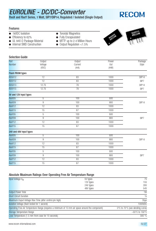
●1kVDC Isolation ●Efficiency to 62%●UL 94V-O Package Material ●Internal SMD Construction●Toroidal Magnetics ●Fully Encapsulated●MTTF up to 2.4 Million Hours ●Output Regulation <1.5%FeaturesAbsolute Maximum Ratings Over Operating Free Air Temperature RangeInput Voltage V IN5V types 7V 12V types 15V 24V types 28V 48V types54V Output Power Total 1W Short Circuit Duration1s Maximum Ouput Voltage Rise Time (after control pin high)35µs Isolation Voltage (flash tested for 1 second)1000VDCOperating Free Air Temperature Range (requires a minimum of 10 mm air space around the component) 0°C to 70°C (see derating curve)Storage Temperature Range–55°C to 150°CLead Temperature (1.5 mm from case for 10 seconds)300 °CTypical Isolation Capacitance (pF)Part Number Output Voltage (V)0509121315R05X/Yxx2832333139R12X/Yxx486368–69R24X/Yxx84106132–152R48X/Yxx547592–109Electrical Specifications (measured at T A = 25°C,at nominal input voltage and rated output current unless otherwise specified)Input Voltage Range V IN(continuous operation)5V types5V±5%12V types12V±5%24V types24V±5%48V types48V±5% Load Voltage Regulation (10% load to 100% full load)0.9% typ./ 1.5% max. Line Voltage Regulation (depending on the Type)0.25% / 1.0% of V IN Output Voltage Accuracy (control pin open circuit)±5% Input Reflected Ripple (20MHz band limited)40mVp-p max. Output Ripple (20MHz band limited)60mVp-p max. Insulation Resistance (at 500VDC)100MΩmin. Efficiency (at full load)5V output types45% min./ 50% typ.9V,12V and 15V output types55% min./ 62% typ. Temperature Drift (V OUT)0.03% per °C max. Temperature Rise above Ambient (at full load)8°C max. Switching Frequency at Full Load (depending on the type)80kHz typ. Package Weight SIP and DIP 5/12/24V types 2.3 gSIP and DIP 48V types 2.9 g MTTF 1) (depending on the type)–25°C165kHrs min./ 2406kHrs max.+25°C135kHrs min./ 1307kHrs max.+70°C69kHrs min./ 144kHrs max.1).Calculated using MIL-HDBK-217F with nominal input voltage at full load.Please contact us,if you need exact parameters for the converter you have selected.Typical Characteristics,Tolerance Envelope and Temperature Derating GraphPackage Style and Pinning (mm)。
ADM3054中文资料
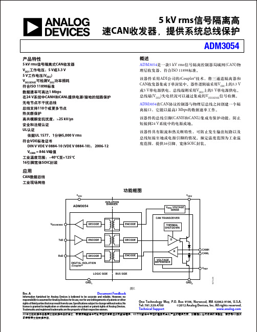
应用
CAN数据总线 工业现场网络
功能框图
VDD1 ISOLATION BARRIER VDD2 VOLTAGE SENSE CAN TRANSCEIVER VDD2SENSE DECODE ENCODE THERMAL SHUTDOWN VDD2
ADM3054
TxD
ENCODE
DECODE
D
R RxD DECODE DIGITAL ISOLATION iCoupler® LOGIC SIDE BUS SIDE ENCODE VOLTAGE REFERENCE
IDD1 IDD2
2.5
3.0 10 75 55
mA mA mA mA RL = 60 Ω,见图28 RL = 60 Ω,见图28 RL = 60 Ω,见图28
VIH VIL IIH, IIL VCANL, VCANH VCANH VCANL VOD VOD ISCCANH ISCCANH ISCCANL
Document Feedback One Technology Way, P.O. Box 9106, Norwood, MA 02062-9106, U.S.A. Tel: 781.329.4700 ©2012 Analog Devices, Inc. All rights reserved. Technical Support
修订历史
2012年12月—修订版0至修订版A 更改“特性”部分 ............................................................................. 1 “法规信息(待定)”部分更改为“法规信息”部分 ...................... 5 更改表3的标题 .............................................................................. 5 “VDE 0884绝缘特性(待定)”部分更改为“VDE 0884 绝缘特性“部分 .............................................................................. 6 2011年10月—修订版0:初始版
贴片发光二极管SMDLED产品型号说明

TOP LED
TOP LED是指顶面发光、平面发光的LED。即,LED的 表面不是半圆的,而是平面的。
1.传统的直插式小功率LED、流明式的大功率LED,都 是透镜式封装的。LED发光的正面是类似半圆形的结 构。
2.为了简化封装工艺,目前很多贴片式的LED,都是 直接用胶水把LED封装成平面式的结构。这一类型, 统称为TOP LED。
2200- B0 12000nm
380-420nm G0
Blue(蓝) Green(绿)
BI Bicolor(双 色)
TR Tricolor(三 ห้องสมุดไป่ตู้)
Y0 Yellow(黄)
YG Yellow Green(黄 绿)
615635nm
450475nm
510530nm
580595nm
565575nm
功率型系列
SMD LED Part No. Description 产品型号说明
ZT
X X XX
XX
X
X
X XXX
ZT
X X XX
XX
XX
X XXX
TOP LED 公司名称代码
显示指数 色温代码 晶片数量 功率型系列 发光颜色
外型尺寸: 3528/3014/2835等
中之光电
东莞市中之光电科技有限公司
专业生产贴片发光二极管
75-7000-9000K 95-9000-13000K
显示指数
60-65显色性 65-70显色性 70-75显色性 75-80显色性 80-85显色性 85-90显色性 90-95显色性 95-100显色性 00-无显色性要求
感谢下 载
东莞市中之光电科技有限公司成立于2008年,位于东莞市松山湖国家高新科 技产业园区,厂房面积7万平方米,占地约80亩,是集研发、生产和销售贴片 LED灯珠一体的国家高新技术企业,贴片LED灯珠年产量达3600KK。
赛米控丹佛斯电子 SEMiX205BT07F3SC4 数据表

© by SEMIKRONRev. 2.0–09.06.20221®5T-Type Bridge RectifierSEMiX205BT07F3SC4 Features*•Solderless assembling solution with PressFIT signal pins and screw power terminals•IGBT 3 High Speed Trench Technology•Silicon Carbide (SiC) Free-wheeling Schottky diodes : Diode 1 (D1...D4)•Silicon anti-parallel diodes , Diode 2 (D5 (8)•V CE(sat) with positive temperature coefficient•Low inductance case•Reliable mechanical design with injection moulded terminals and reliable internal connections •UL recognized file no. E63532•NTC temperature sensor insideTypical Applications•High Frequency Resonant Converter •Interleaved Active Rectifier •UPSRemarks•Case temperature limited to T C =125°C max.•Product reliability results are valid for T jop =150°C•For storage and case temperature with TIM see document “TP(HALA P8) SEMiX 5p”Absolute Maximum Ratings SymbolConditions Values UnitIGBT 1V CES T j =25°C 650V I C T j =175°CT c =25°C 223A T c =80°C167A I Cnom 200A I CRM400A V GES -20 (20)V t psc V CC =400V V GE ≤ 15V V CES ≤ 650VT j =150°C5µs T j-40 (175)°CAbsolute Maximum Ratings SymbolConditions Values UnitDiode 1V RRM T j =25°C 1200V I F T j =175°CT c =25°C 161A T c =80°C123A I FRM 280A I FSM 8.3ms sin 180°T j =25°C 729A T j =150°C-A T j-40 (175)°CAbsolute Maximum Ratings SymbolConditions Values UnitDiode 2V RRM T j =25°C 650V I F T j =175°CT c =25°C 250A T c =80°C183A I FRM 400A I FSM 10ms sin 180°T j =25°C 1476A T j =150°C1224A T j-40 (175)°CAbsolute Maximum Ratings SymbolConditions Values UnitModule I t(RMS)300A T stg module without TIM -40...125°C V isolAC sinus 50Hz, t =1min4000V2Rev. 2.0–09.06.2022© by SEMIKRON®5T-Type Bridge RectifierSEMiX205BT07F3SC4 Features*•Solderless assembling solution with PressFIT signal pins and screw power terminals•IGBT 3 High Speed Trench Technology•Silicon Carbide (SiC) Free-wheeling Schottky diodes : Diode 1 (D1...D4)•Silicon anti-parallel diodes , Diode 2 (D5 (8)•V CE(sat) with positive temperature coefficient•Low inductance case•Reliable mechanical design with injection moulded terminals and reliable internal connections •UL recognized file no. E63532•NTC temperature sensor insideTypical Applications•High Frequency Resonant Converter •Interleaved Active Rectifier •UPSRemarks•Case temperature limited to T C =125°C max.•Product reliability results are valid for T jop =150°C•For storage and case temperature with TIM see document “TP(HALA P8) SEMiX 5p”IGBT 1V CE(sat)I C =200A V GE =15V chiplevel T j =25°C 1.85 2.22V T j =150°C 2.25 2.55V V CE0chiplevel T j =25°C 1.10 1.20V T j =150°C 1.00 1.10V r CEV GE =15V chiplevelT j =25°C 3.8 5.1m ΩT j =150°C6.37.3m ΩV GE(th)V GE = V CE , I C =3.2mA4.25.1 5.6V I CES V GE =0V,V CE =650V, T j =25°C 0.2mA C ies V CE =25V V GE =0Vf =1MHz 12.2nF C oes f =1MHz 0.76nF C res f =1MHz0.36nF Q G V GE =- 7 V...+ 15 V 1500nC R Gint T j =25°C 1.0Ωt d(on)V CC =300V I C =200A R G on =15ΩR G off =15Ωdi/dt on =1000A/µs di/dt off =2100A/µs V GE =+15/-7V dv/dt =2000V/µs T j =150°C 125ns t r T j =150°C 155ns E on T j =150°C 11mJ t d(off)T j =150°C 1100ns t f T j =150°C 77ns E off T j =150°C 7.9mJR th(j-c)per IGBT0.24K/W R th(c-s)per IGBT (λgrease=0.81 W/(m*K))0.03K/W R th(c-s)per IGBT, pre-applied phase change material0.018K/WCharacteristics SymbolConditionsmin.typ.max.UnitDiode 1V F I F =120A V GE =0V chiplevel T j =25°C 1.45 1.75V T j =150°C 1.85 2.20V V F0chiplevel T j =25°C 0.95 1.05V T j =150°C 0.820.92V r F chiplevelT j =25°C 4.2 5.8m ΩT j =150°C8.611m ΩI R V R = V RRM , T j =25°C5mA C j V R =800V, f =0.1MHz, T j =25°C 507nF Q c V R =800V, , T j =25°C 0.66µCR th(j-c)per diode0.31K/W R th(c-s)per diode (λgrease=0.81 W/(m*K))0.061K/W R th(c-s)per diode, pre-applied phase change material0.04K/W© by SEMIKRONRev. 2.0–09.06.20223®5T-Type Bridge RectifierSEMiX205BT07F3SC4 Features*•Solderless assembling solution with PressFIT signal pins and screw power terminals•IGBT 3 High Speed Trench Technology•Silicon Carbide (SiC) Free-wheeling Schottky diodes : Diode 1 (D1...D4)•Silicon anti-parallel diodes , Diode 2 (D5 (8)•V CE(sat) with positive temperature coefficient•Low inductance case•Reliable mechanical design with injection moulded terminals and reliable internal connections •UL recognized file no. E63532•NTC temperature sensor insideTypical Applications•High Frequency Resonant Converter •Interleaved Active Rectifier •UPSRemarks•Case temperature limited to T C =125°C max.•Product reliability results are valid for T jop =150°C•For storage and case temperature with TIM see document “TP(HALA P8) SEMiX 5p”Diode 2V F = V EC I F =200A V GE =0V chiplevel T j =25°C 1.40 1.76V T j =150°C 1.38 1.77V V F0chiplevel T j =25°C 1.04 1.24V T j =150°C 0.850.99V r Fchiplevel T j =25°C 1.78 2.6m ΩT j =150°C 2.7 3.9m ΩI RRM I F =200A V GE =-7V V R =300V T j =150°C -A Q rr T j =150°C -µC E rr T j =150°C-mJR th(j-c)per diode0.32K/W R th(c-s)per diode (λgrease=0.81 W/(m*K))0.012K/W R th(c-s)per diode, pre-applied phase change material0.008K/WCharacteristics SymbolConditions min.typ.max.UnitModule L+measured between + to M30nH L-measured between M to -36nH R CC'+EE'measured between terminal 4and 1T C =25°C 1.2m ΩT C =125°C 1.65m ΩR th(c-s)1calculated without thermal coupling 0.0019K/W R th(c-s)2including thermal coupling,T s underneath module (λgrease =0.81 W/(m*K))0.003K/W R th(c-s)2including thermal coupling,T s underneath module, pre-applied phase change material 0.002K/W M s to heat sink (M5)36Nm M t to terminals (M6)36Nm w398gCharacteristics SymbolConditionsmin.typ.max.UnitTemperature SensorR 100T c =100°C (R 25=5 k Ω)493 ± 5%ΩB 100/125R (T)=R 100exp[B 100/125(1/T-1/T 100)]; T[K];3550 ±2%K4Rev. 2.0–09.06.2022© by SEMIKRON© by SEMIKRON Rev. 2.0–09.06.202256Rev. 2.0–09.06.2022© by SEMIKRONThis is an electrostatic discharge sensitive device (ESDS) due to international standard IEC 61340.*IMPORTANT INFORMATION AND WARNINGSThe specifications of SEMIKRON products may not be considered as guarantee or assurance of product characteristics ("Beschaffenheitsgarantie"). The specifications of SEMIKRON products describe only the usual characteristics of products to be expected in typical applications, which may still vary depending on the specific application. Therefore, products must be tested for the respective application in advance. Application adjustments may be necessary. The user of SEMIKRON products is responsible for the safety of their applications embedding SEMIKRON products and must take adequate safety measures to prevent the applications from causing a physical injury, fire or other problem if any of SEMIKRON products become faulty. The user is responsible to make sure that the application design is compliant with all applicable laws, regulations, norms and standards. Except as otherwise explicitly approved by SEMIKRON in a written document signed by authorized representatives of SEMIKRON, SEMIKRON products may not be used in any applications where a failure of the product or any consequences of the use thereof can reasonably be expected to result in personal injury. No representation or warranty is given and no liability is assumed with respect to the accuracy, completeness and/or use of any information herein, including without limitation, warranties of non-infringement of intellectual property rights of any third party. SEMIKRON does not assume any liability arising out of the applications or use of any product; neither does it convey any license under its patent rights, copyrights, trade secrets or other intellectual property rights, nor the rights of others. SEMIKRON makes no representation or warranty of non-infringement or alleged non-infringement of intellectual property rights of any third party which may arise from applications. Due to technical requirements our products may contain dangerous substances. For information on the types in question please contact the nearest SEMIKRON sales office. This document supersedes and replaces all information previously supplied and may be superseded by updates. SEMIKRON reserves the right to make changes.7。
- 1、下载文档前请自行甄别文档内容的完整性,平台不提供额外的编辑、内容补充、找答案等附加服务。
- 2、"仅部分预览"的文档,不可在线预览部分如存在完整性等问题,可反馈申请退款(可完整预览的文档不适用该条件!)。
- 3、如文档侵犯您的权益,请联系客服反馈,我们会尽快为您处理(人工客服工作时间:9:00-18:30)。
8700 E. Thomas Road Scottsdale, AZ 85251Tel: (480) 941-6300Fax: (480) 947-1503
DESCRIPTION (300 watt)
This TRANSIENT VOLTAGE SUPPRESSOR (TVS) array is packaged in an SO-8 configuration giving protection to 4 Bidirectional data or interface lines. It is designed for use in applications where protection is required at the board level from voltage transients caused by electrostatic discharge (ESD) as defined in IEC 1000-4-2, electrical fast transients (EFT) per IEC 1000-4-4 and effects of secondary lighting.
These TVS arrays have a peak power rating of 300 watts for an 8/20 µsec pulse. This array is suitable for protection of sensitive circuitry consisting of TTL, CMOS DRAM’s, SRAM’s, HCMOS, HSIC microprocessors, and I/O transceivers. The SMDAXXC-4 product provides board level protection from static electricity and other induced voltage surges that can damage sensitive circuitry.
FEATURES
MECHANICAL
• Protects up to 4 Bidirectional lines
•Molded SO-8 Surface Mount
• Surge protection Per IEC 1000-4-2, 1000-4-4•Weight: 0.066 grams (approximate)
•
SO-8 Packaging
•Marking: Logo, device number, date code •
Pin #1 defined by DOT on top of package
MAXIMUM RATINGS
PACKAGING
• Operating Temperatures: -550C to +1500
C •Tape & Reel EIA Standard 481-1-A • Storage Temperature: -550C to +1500C
•13 inch reel 2,500 (OPTIONAL)
• Peak Pulse Power: 300 Watts (8/20 µsec, Figure 1)•
Carrier tubes 95 pcs per (STANDARD)
•
Pulse Repetition Rate: <.01%
ELECTRICAL CHARACTERISTICS PER LINE @ 250C Unless otherwise specified
STAND OFF VOLTAG
E V WM VOLTS BREAKDOWN VOLTAGE
V BR @1 mA
VOLTS CLAMPING VOLTAGE
V C
@ 1 Amp (FIGURE 2)VOLTS
CLAMPING VOLTAGE
V C
@ 5 Amp (FIGURE 2)VOLTS
LEAKAGE CURRENT
I D @ V WM
µA CAPACITANCE (f=1 MHz)
@0V C
pF TEMPERATURE COEFFICIENT
OF V BR áVBR mV/°C
PART NUMBER DEVICE MARKING
MAX
MIN MAX MAX MAX TYP MAX SMDA03C-4REA 3.347.09.0200300-5SMDA05C-4REB 5.0 6.09.8114002003SMDA12C-4REC 12.013.319.024118510SMDA15C-4RED 15.016.724.030114013SMDA24C-4
REE
24.0
26.7
43.0
55
1
90
30
NOTE: TVS product is normally selected based on its stand off Voltage V WM . Product selected voltage should be equal to or greater than the continuous peak operating voltage of the circuit to be protected.
Application: The SMDAXXC-4 product is designed for transient voltage suppression protection of ESD sensitive components at the board level. It is an ideal product to be used for protection of I/O Transceivers.
SMDA03C-4 thru SMDA24C-4
WAVE FORMS
Peak Pulse Power Vs Pulse Time Pulse Wave Form
p
INCHES MILLIMETERS
MIN
MIN MAX
MAX
0.188 4.77 5.00
0.197
0.150 3.81 4.01
0.158
0.053 1.35 1.75
0.069
0.021
0.0110.280.53
0.0160.41 1.27
0.050。
