ISP上位机使用及BOOT更新说明
WY8S8003系列ISP用户手册说明书
WY8S8003系列ISP用户手册Ver1.0.1上海维安半导体有限公司Wayon Semiconductor Co.,Ltd.目录1.概述 (1)1.1.软件简介 (1)1.2.MCU与下载盒连接示意图 (1)1.3.ISP升级流程 (2)1.3.1.一键下载 (2)1.3.2.普通下载 (7)2.通信协议 (11)2.1.命令列表 (11)2.2.串口协议格式 (11)2.2.1.下载命令请求协议定义 (11)2.2.2.下载命令回复协议定义 (12)2.3.指令说明 (12)2.3.1.CMD_SYNC (12)2.3.2.CMD_UPDATE_APROM (13)2.3.3.CMD_UPDATE_APROM_END (13)3.软件基本说明 (15)3.1.软件安装 (15)3.2.软件界面说明 (15)4.修订历史 (16)1. 概述ISP 是在系统编程的缩写,这个功能可以让用户在软件控制下,不需要将MCU 从产品上取下来进行应用程序升级。
针对8051 MCU 产品,我们通过串口提供ISP 升级方法,用户需要在LDROM 区域下载BOOT 程序。
将MCU 调试下载器或其他串口工具和MCU 相连接,并利用WayOn ISP Programer Tool 软件完成升级。
1.1.软件简介WayOn ISP Programer Tool 是维安半导体有限公司针对8051系列MCU 开发的ISP 下载工具,配合8051 MCU 调试器支持一键下载功能。
工具支持UART 通讯方式,默认采用38400的波特率,下载文件支持BIN/HEX 格式,BOOT 程序支持的串口管脚RXD 为引脚P04,TXD0为引脚P05,RST 引脚为P20。
维安8051 MCU 支持默认从APROM 启动,配合维安调试器的串口和GPIO 管脚连接目标MCU 串口和P20(P20配置为RST ),完成ISP 升级。
同时支持默认选择从LDROM 启动,利用普通串口连接目标MCU 串口,在上电启动周期(客户可配)之内完成升级启动完成ISP 升级。
BootUpdate说明书
IPC升级修复工具说明书
使用步骤
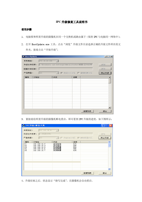
1.电脑要和所需升级的摄像机在同一个交换机或路由器下(保持IPC与电脑同一网络中);2.打开BootUpdate.exe工具,点击“浏览”升级文件目录选择正确的升级文件所在的文件夹,接着点击“开始升级”;
3.紧接着给所需升级的摄像机断电重启,即可看到IPC升级的进度,如下图所示:
4,升级结束之后,状态显示“烧写完成”,且摄像机会自动重启。
附:工具相关功能讲解:
产品描述:
1.选择本机联网的IP地址,一般只有一个,不用改动。
2.升级文件目录,默认是程序运行目录,点击“浏览...”按钮可更换目录
3.该软件可以同时对不同型号的ipc进行升级,只需要将要升级的文件放到同一个文件夹下即可
4.升级boot分区,默认选中,选中此选项后,会对boot分区进行升级
5.擦除配置分区,默认不选中,但当IPC使用过程中死机或重启类似异常时,升级时可勾上
6.开始升级,浏览并选择正确升级文件后可开始升级
7.点击开始升级后,断电重启摄像机会进行升级,框内会提示发送数据与烧写数据,烧写完成即表示升级完成。
8040路由器VRP1.7x的BootROM升级指导书
8040路由器VRP1.7x的Boot ROM升级指导书目录一、BootRom版本说明 (2)二、从7.x版本之前的BOOTROM版本(如4.36)升级到7.x版本 (2)三、从7.x版本升级到之后的版本(如7.00版本到7.02版本) (3)四、从7.x版本退回到以前的版本(如7.02版本到4.36版本) (4)五、内存升级说明 (4)六、DRAM技术介绍 (7)一、BootRom版本说明为方便路由器维护和用户的方便,VRP1.x版本下的模块化路由器(1760/1760B/2610/2611/2620/2621/2630E/2631E/3640E/3680E)支持统一的BootRom版本(7.x版本,目前最新版本为7.02),该版本之前的BootRom版本如4.x要区分路由器的型号。
除此之外,BootRom7.x还支持内存的自动识别,因此支持内存升级的功能更强大,另外,还支持系统启动时按“CTRl+B”及“CTRL+D”两种方式进入的菜单下的BootRom升级,而BootRom7.x之前的版本仅支持按“CTRL+D”方式进入的菜单下的BootRom升级。
但在扩展内存并将BootRom升级到7.x版本时,路由器VRP主机版本需要VRP1.74 Release 0101版本之后的版本,这样才能保证扩展后的内存的有效利用。
BootRom7.x可以支持低于VRP1.74 Release 0101版本之前的版本,只是不能保证扩展内存后的正常或有效的使用。
VRP1.74 Release 0101及之后的版本还支持ftp方式的BootRom程序升级。
升级原则:(1)直接烧片时,中低端路由器的老型号(包括X86平台、8240主板、68360主板)路由器的BootRom 采用的是AMD型号,采用8241和8245主板(17、2610/2611和新3680E路由器)和46路由器的BootRom采用的SGS型号,7.02的版本的软件在上述的路由器中是一样的,7.00之前的版本之前分不同的路由器有不同的BootRom程序。
STM32之USB固件升级IAPUSB程序升级上位机软件操作
STM32之USB固件升级IAPUSB程序升级上位机软件操作STM32之USB固件库IAP升级(以下全部为实际操作所得)最近做了STM32通过USB程序升级功能,也就是所谓的DFU,所使⽤的程序为ST公司提供的例⼦程序(位置为:安装⽬录/ARM/Examples/ST/STM32F10xUSBLib/Demos/Device_Firmware_Upgrade),此⽂件夹包含多两个⼯程,project⽂件夹存放的是⽤来升级的程序-IAP,binary⽂件夹存放的是⽤户程序—APP。
⼀、USB升级程序打开Project⾥⾯的⼯程(⽤什么软件打开就不⽤我讲了吧),如果你电脑上有Source Insight就更好了,⽅便查阅。
从MAIN⾥⾯我们可以知晓,程序先判断某个按键是否按下(这个可以根据你的实际电路设计来修改),如果按下则进⼊升级功能程序,否则就跳转到APP程序,也就是⽤户程序。
不多说了,直接上程序。
i f (DFU_Button_Read() == 0x00)//如果未按下1{ /* Test if user code is programmed starting from address 0x8003000 */if (((*(vu32*)ApplicationAddress) & 0x2FFE0000 ) == 0x20000000) 2{ /* Jump to user application */JumpAddress = *(vu32*) (ApplicationAddress + 4); 3Jump_To_Application = (pFunction) JumpAddress; 4/* Initialize user application's Stack Pointer */__MSR_MSP(*(vu32*) ApplicationAddress); 5Jump_To_Application(); 6}} /* Otherwise enters DFU mode to allow user to program his application */1、判断按键是否按下,如果未按下,则准备进⼊⽤户程序区,是准备哦,因为后⾯还有判断语句。
USB ISP 制做和使用过程记录
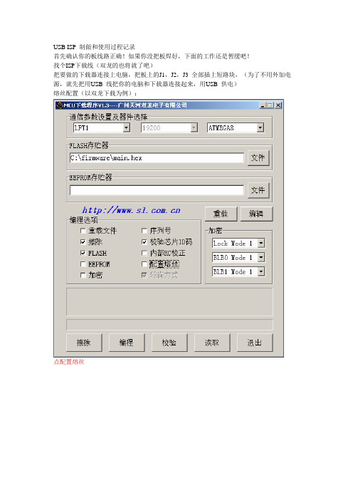
USB ISP 制做和使用过程记录首先确认你的板线路正确!如果你没把板焊好,下面的工作还是暂缓吧!找个ISP下载线(双龙的也将就了吧)把要做的下载器连接上电脑,把板上的J1,J2,J3 全部插上短路块,(为了不用外加电源,就先把用USB 线把你的电脑和下载器连接起来,用USB 供电)熔丝配置(以双龙下载为例):点配置熔丝点确定返回就行了回主窗口后直接点编程就可以了。
其实这时候你的USBISP 下载器已经完成了把你的USB 线拔下再插上,你的电脑会告诉你找到新硬件,并且有一个指示灯会亮(如果没有的话,那你就要检查你的板有没有问题或是以上步骤有没有出错了)接下来给你的新硬件安装驱动程序!驱动文件在”驱动”目录里面Select “Next>”Select “Next>”选择你下载的文件夹里的那个”驱动”文件夹就行了然后Next>“Finish”!好了驱动也装完了,接下来就可以用它来向你的其它目标板下载程序。
把你的双龙下载线的那个10PIN 线拔过来用,一端插下载器的10PIN 插座,一端插目标板就行了.打开那个下载来的上位机软件吧usbisp diy\PC_App_Isp\ progisp.ExE上面是默认的Mega16 的配置(内部8MHz 时钟),基本上这样就行了,要做什么其它配置,自已去看数据手册!(1 是选中编程该位,0 就不说了)重要说明:三个短路块的问题在制做下载器的时候这三个短路块J1,J2,J3 都要插上,但在连接目标板的时候一定注意如果你的目标板上已经有电源了,那一定要拔掉J1(建议在目标板上另加电源,拔掉J1)如果目标板上没有电源,那不拔J1 目标板可以从USB 取电。
J2 无关紧要,拔不拔都没关系,J3 是影响下载速度的。
拔掉的话就是以硬件SPI 高速下载,不拔就是软件模拟SPI 低速下载。
根据你的目标板时钟速度来定,一般用高速下载了,除非你的目标板上是用的Atiny或者AT90 之类的MCU 或者你的MCU 一定要工作在低速下。
8MP ISP 新相机移植 (AN13713)说明书
AN137138MP ISP New Camera PortingRev. 0 — 24 August 2022Application note8MP ISP New Camera Porting 1Building ISP module, drivers, and librariesTo run a camera sensor on the i.MX 8MP board, build the ISP module, drivers, andlibraries (including <cam>.ko, <cam>.so, and <cam>.drv) for your sensor. In addition,get the camera calibration files (.xml), dewarp calibration files (.json), and sensor-configuration files (.cfg) ready to set correct ISP parameters and stream mode.1.If you use NXP supported sensors (such as OS08A20), get the drivers and librariesfrom "yocto imx-isp" and "yocto vvcam" after you build the whole ISP module.2.Find detailed instructions for writing code or building new drivers and libraries in"iMX8MP_CAMERA_DISPLAY_GUIDE.pdf", available at the NXP website. Togenerate sensor-calibration files, calibrate the new camera sensor in a lab and thengenerate the ".xml" files using the camera calibration tool and the ".json" files usingthe dewarp calibration tool. Sensor-configuration files can be easily created by editingNote: If you use a flat len sensor and decide not to calibrate the new dewarpconfiguration files, bypass the ISP's dewarp feature. Use the dewarp configuration files ofother sensors with the same resolution and set the "dewarp bypass" parameter to "true".Figure 1. Bypass parameter2Building the ISP moduleTo build the ISP module, get the correct versions of toolchain, linux kernel, "yocto imx-isp" and "yocto vvcam" on your local machine.8MP ISP New Camera Porting2.1Creating the i.MX Yocto SDK and installing the toolchain1.2.3.4.image-full-armv8a-imx8mp-lpddr4-evk-toolchain-5.15-kirkstone.sh" file.5.The toolchain path is "/opt/my-tool-chain-path".2.2Building the NXP kernel1.Download the correct version of the NXP kernel from https:///external/imx/linux-imx.2.Note: The build path of the Linux kernel should be the path of the "build_v8" folder.3Building the "yocto imx-isp" (details are in "build-all-isp.sh")1.folder.8MP ISP New Camera Porting 2.4Building "yocto vvcam" (details are in "build-all-vvcam.sh")1.Download the correct version of "yocto vvcam" from https:///external/imx/isp-vvcam.In Yocto, "vvcam" is in the "build-wayland-8mp/tmp/work/imx8mpevk-poky-linux/kernel-module-isp-vvcam" folder.2.Build "vvcam" using the following command (you can also use the "build-all-5Copying useful files listed below to a build-out directoryKernel:•".dtb" files (build_v8/arch/arm64/boot/dts/freescale/imx8mp-evk-*.dtb)•Image (build_v8/arch/arm64/boot/Image)•"imx-media-dev.ko" (build_v8/drivers/stagging/media/imx/imx-media-dev.ko)Imx-isp:•Libraries (isp-imx-4.2.2.18.0/appshell/build/generated/[build mode]/lib/*.so*)8MP ISP New Camera Porting •Sensor-related files (e.g. "isp-imx-4.2.2.18.0/appshell/build/generated/[build mode]/bin/OS08a20.*" and "isp-imx-4.2.2.18.0/appshell/build/generated/[build mode]/bin/os08a20.*")•"isp_media_server" (isp-imx-4.2.2.18.0/appshell/build/generated/[build mode]/bin/isp_media_server)•Test files (isp-imx-4.2.2.18.0/appshell/build/generated/[build mode]/bin/test_*)•Sensor-configuration files (isp-imx-4.2.2.18.0/appshell/build/generated/[build mode]/bin/Sensor*_Entry.cfg)•"vvext" (isp-imx-4.2.2.18.0/appshell/build/generated/[build mode]/bin/vvext)•Dewarp configurations (isp-imx-4.2.2.18.0/dewarp/dewarp_config/*)•Scripts to run the ISP ("isp-imx-4.2.2.18.0/imx/start_isp.sh" and "isp-imx-4.2.2.18.0/imx/run.sh")Vvcam:•Sensor driver (isp-vvcam/vvcam/v4l2/sensor/os08a20/os08a20.ko)•"vvcam-dwe" (isp-vvcam/vvcam/v4l2/video/vvcam-dwe.ko)•"vvcam-isp" (isp-vvcam/vvcam/v4l2/video/vvcam-isp.ko)•"vvcam-video" (isp-vvcam/vvcam/v4l2/video/vvcam-video.ko)Note: When building the ISP SDK, keep the Linux and SDK versions the same as theYocto release.6Using SCP to remotely send the files in the build-out directory to EVKNote: "libtinyxml2.so" is required for the build. However, it may not be included inall SDK configurations. You can build this package separately if you have the Yoctoenvironment or download pre-built package from a package distribution repository (suchas ; choose "arm64" with the correct version).7Setting the environment when bootingAfter generating and copying the necessary files into a folder, the ISP folder can look likeFigure 2.8MP ISP New Camera PortingFigure 2. ISP folder8Running ISP and sensor (e.g. OS08A20) on 8MP EVK1.2.3.4.5.6.Reference: "build-all-isp.sh", "build-all-vvcam.sh"9Porting a new camera to the tuning tool1.Download the tuning server and client released by NXP.8MP ISP New Camera Porting2.To enable other sensor tuning, you do not have to rebuild "isp-imx" and "vvcam".After porting your sensor according to the porting guide and building it, you can getthe related sensor files in the "build_output_release" directory. Just push the sensor-3.10Revision history8MP ISP New Camera Porting 11Legal information11.1 DefinitionsDraft — A draft status on a document indicates that the content is still under internal review and subject to formal approval, which may resultin modifications or additions. NXP Semiconductors does not give any representations or warranties as to the accuracy or completeness of information included in a draft version of a document and shall have no liability for the consequences of use of such information.11.2 DisclaimersLimited warranty and liability — Information in this document is believed to be accurate and reliable. However, NXP Semiconductors does not give any representations or warranties, expressed or implied, as to the accuracy or completeness of such information and shall have no liability for the consequences of use of such information. NXP Semiconductors takes no responsibility for the content in this document if provided by an information source outside of NXP Semiconductors.In no event shall NXP Semiconductors be liable for any indirect, incidental, punitive, special or consequential damages (including - without limitation -lost profits, lost savings, business interruption, costs related to the removal or replacement of any products or rework charges) whether or not such damages are based on tort (including negligence), warranty, breach of contract or any other legal theory.Notwithstanding any damages that customer might incur for any reason whatsoever, NXP Semiconductors’ aggregate and cumulative liability towards customer for the products described herein shall be limited in accordance with the Terms and conditions of commercial sale of NXP Semiconductors.Right to make changes — NXP Semiconductors reserves the right to make changes to information published in this document, including without limitation specifications and product descriptions, at any time and without notice. This document supersedes and replaces all information supplied prior to the publication hereof.Suitability for use — NXP Semiconductors products are not designed, authorized or warranted to be suitable for use in life support, life-critical or safety-critical systems or equipment, nor in applications where failure or malfunction of an NXP Semiconductors product can reasonably be expected to result in personal injury, death or severe property or environmental damage. NXP Semiconductors and its suppliers accept no liability for inclusion and/or use of NXP Semiconductors products in such equipment or applications and therefore such inclusion and/or use is at the customer’s own risk.Applications — Applications that are described herein for any of these products are for illustrative purposes only. NXP Semiconductors makes no representation or warranty that such applications will be suitable for the specified use without further testing or modification.Customers are responsible for the design and operation of their applications and products using NXP Semiconductors products, and NXP Semiconductors accepts no liability for any assistance with applications or customer product design. It is customer’s sole responsibility to determine whether the NXP Semiconductors product is suitable and fit for the customer’s applications and products planned, as well as for the planned application and use of customer’s third party customer(s). Customers should provide appropriate design and operating safeguards to minimize the risks associated with their applications and products.NXP Semiconductors does not accept any liability related to any default, damage, costs or problem which is based on any weakness or defaultin the customer’s applications or products, or the application or use by customer’s third party customer(s). Customer is responsible for doing all necessary testing for the customer’s applications and products using NXP Semiconductors products in order to avoid a default of the applicationsand the products or of the application or use by customer’s third party customer(s). NXP does not accept any liability in this respect.Export control — This document as well as the item(s) described herein may be subject to export control regulations. Export might require a prior authorization from competent authorities.Evaluation products — This product is provided on an “as is” and “with all faults” basis for evaluation purposes only. NXP Semiconductors, its affiliates and their suppliers expressly disclaim all warranties, whether express, implied or statutory, including but not limited to the implied warranties of non-infringement, merchantability and fitness for a particular purpose. The entire risk as to the quality, or arising out of the use or performance, of this product remains with customer.In no event shall NXP Semiconductors, its affiliates or their suppliersbe liable to customer for any special, indirect, consequential, punitiveor incidental damages (including without limitation damages for loss of business, business interruption, loss of use, loss of data or information, and the like) arising out the use of or inability to use the product, whether or not based on tort (including negligence), strict liability, breach of contract, breach of warranty or any other theory, even if advised of the possibility of such damages.Notwithstanding any damages that customer might incur for any reason whatsoever (including without limitation, all damages referenced above and all direct or general damages), the entire liability of NXP Semiconductors,its affiliates and their suppliers and customer’s exclusive remedy for all of the foregoing shall be limited to actual damages incurred by customer based on reasonable reliance up to the greater of the amount actually paid by customer for the product or five dollars (US$5.00). The foregoing limitations, exclusions and disclaimers shall apply to the maximum extent permitted by applicable law, even if any remedy fails of its essential purpose.Translations — A non-English (translated) version of a document, including the legal information in that document, is for reference only. The English version shall prevail in case of any discrepancy between the translated and English versions.Security — Customer understands that all NXP products may be subject to unidentified vulnerabilities or may support established security standards or specifications with known limitations. Customer is responsible for the design and operation of its applications and products throughout their lifecyclesto reduce the effect of these vulnerabilities on customer’s applicationsand products. Customer’s responsibility also extends to other open and/or proprietary technologies supported by NXP products for use in customer’s applications. NXP accepts no liability for any vulnerability. Customer should regularly check security updates from NXP and follow up appropriately. Customer shall select products with security features that best meet rules, regulations, and standards of the intended application and make the ultimate design decisions regarding its products and is solely responsiblefor compliance with all legal, regulatory, and security related requirements concerning its products, regardless of any information or support that may be provided by NXP.NXP has a Product Security Incident Response Team (PSIRT) (reachableat *************) that manages the investigation, reporting, and solution release to security vulnerabilities of NXP products.11.3 TrademarksNotice: All referenced brands, product names, service names, and trademarks are the property of their respective owners.NXP — wordmark and logo are trademarks of NXP B.V.8MP ISP New Camera PortingContents1Building ISP module, drivers, and libraries (2)2Building the ISP module (2)2.1Creating the i.MX Yocto SDK and installingthe toolchain (3)2.2Building the NXP kernel (3)3Building the "yocto imx-isp" (details are in"build-all-isp.sh") (3)4Building "yocto vvcam" (details are in"build-all-vvcam.sh") (4)5Copying useful files listed below to abuild-out directory (4)6Using SCP to remotely send the files inthe build-out directory to EVK (5)7Setting the environment when booting (5)8Running ISP and sensor (e.g. OS08A20)on 8MP EVK (6)9Porting a new camera to the tuning tool (6)10Revision history (7)11Legal information (8)Please be aware that important notices concerning this document and the product(s)described herein, have been included in section 'Legal information'.。
详解STM32 ISP设置及使用说明
详解STM32 ISP设置及使用说明(原创)1. STM32的BOOT概述STM32三种启动模式对应的存储介质均是芯片内置的,它们是:用户闪存:BOOT1=x BOOT0=0芯片内置的Flash,即主存储器FlashSRAM:BOOT1=1 BOOT0=1芯片内置的SRAM 区,就是内存啦。
系统存储器:BOOT1=0 BOOT0=1芯片内部一块特定的区域,叫做系统存储器。
芯片出厂时在这个区域预置了一段Bootloader,就是通常说的ISP程序。
这个区域的内容在芯片出厂后没有人能够修改或擦除,即它是一个ROM 区。
在每个STM32的芯片上都有两个管脚BOOT0和BOOT1,这两个管脚在芯片复位时的电平状态决定了芯片复位后从哪个区域开始执行程序,见下表:BOOT1=x BOOT0=0 从用户闪存启动,这是正常的工作模式。
BOOT1=0 BOOT0=1 从系统存储器启动,这种模式启动的程序功能由厂家设置。
BOOT1=1 BOOT0=1 从内置SRAM 启动,这种模式可以用于调试。
要注意的是,一般不使用内置SRAM 启动(BOOT1=1 BOOT0=1),因为SRAM 掉电后数据就丢失。
多数情况下SRAM 只是在调试时使用,也可以做其他一些用途。
如做故障的局部诊断,写一段小程序加载到SRAM 中诊断板上的其他电路,或用此方法读写板上的Flash 或EEPROM 等。
还可以通过这种方法解除内部Flash 的读写保护,当然解除读写保护的同时Flash 的内容也被自动清除,以防止恶意的软件拷贝。
一般BOOT0 和BOOT1 跳线都跳到0(GND),即正常的从片内Flash运行,只是在ISP下载的情况下,需要设置BOOT0=1,BOOT1=0 ,下载完成后,把BOOT0 的跳线接回0,这样系统可以正常运行了。
对于一般的应用来说,直接把BOOT0 和BOOT1 引脚接地即可,不用设置跳线,使用IAR 调试程序时可以选择RAM 调试还是Flash 调试,与BOOT0 和BOOT1 的配置无关。
单片机ISP、IAP和ICP几种烧录方式的区别
单片机ISP、IAP和ICP几种烧录方式的区别单片机ISP、IAP和ICP几种烧录方式的区别玩单片机的都应该听说过这几个词。
一直搞不太清楚他们之间的区别。
今天查了资料后总结整理如下。
ISP:In System Programing,在系统编程IAP:In applicating Programing,在应用编程ICP:In Circuit Programing,在电路编程ISP是指可以在板级上进行编程,也就是不用拆芯片下来,写的是整个程序,一般是通过ISP接口线来写。
IAP虽然同样也是在板级上进行编程,但是是自已对自已进行编程,在应用中进行编程,也即可以只是更改某一部分而不影响系统的其它部分,另外接口程序是自已写的,这样可以进行远程升级而不影响应用。
打个比喻吧:1、ISP是把房子拆了再重造一间,那么在造好之前当然是不能住人的啦!2、IAP是在造好的房子里边进行一些装修,当然人可以继续住啦!ICP是在电路编程,是LPC芯片的编程方式,相当于ATMEL的ISP,而LPC的ISP就相当于ATMEL的IAP了。
ISP于IAP的区别ISP:in system programming, 在系统编程IAP: in applicatin programming 在应用编程但两者的操作方式,结果和应用场合有什么区别什么是ISP:用写入器将COD e烧入,不过,芯片可以在目标板上,不用取出来,在设计目标板的时候就将接口设计在上面,所以叫"在系统编程",即不用脱离系统;什么是IAP:在应用编程,有芯片本身(或通过外围的芯片)可以通过一系列操作将code写入,比如一款支持Iap的单片机,内分3个程序区,1作引导程序区,2作运行程序区,3作下载区,芯片通过串口接收到下载命令,进入引导区运行引导程序,在引导程序下将new code内容下载到下载区,下载完毕并校验通过后再将下载区内容复制到2区,运行复位程序,则Iap完成;应用场合:1,ISP 程序升级需要到现场解决,不过好一点的是不必拆机器了;2,IAP 如果有网管系统的话,用网管下载一切搞定,人不用跑来跑去, 这可能是他们的优点或应用吧在线编程目前有两种实现方法:在系统编程(ISP)和在应用编程(IAP)。
STCISP程序使用说明(针对新版本)

STCISP程序使用说明以下是烧录程序的主要界面。
烧录过程非常简单,操作也非常简单。
图中红色的五个大数字就表示了整个过程。
简简单单的六步就可以了。
启动本烧录程序后,第一步就是选择烧录器件。
本烧录软件支持STC全系列的51单片机芯片,因此,第一步必须选择相对应的型号。
由于本实验板选用的单片机芯片就是本烧录软件首次启动默认的型号,所以,本项一般都不需要选择。
另外,“AP Memory”是指该芯片的内存大小和起止地址,根据器件型号自动更改,不必理会。
选择了器件型号,第二步就应该选择将要被烧录的HEX机器码文件。
HEX文件由单片机开发环境输入、编辑代码,最后编绎产生。
至于如何产生HEX文件,很多资料也都有介绍。
选好了文件后,大家可以发现“文件校验和”中的数据发生了变化,大家可以通过留意这个数据是否变化来确定打开文件是否成功,或者文件刷新是否有更改。
当然,文件打开后,会显示在右边的数据区,大家也可以观查右边数据区是否有更改。
不过,当数据太多时,更改的地方又很少时,观查“文件校验和”会更快更准确。
选好了器件,选好了文件,第三步就可以设置串口和串口通信速度了。
串口是一个九针的插座。
为了让通信可靠,我们可以适当的选低一些的速度,这个串口线较长时非常重要。
但本站长经过多次烧录实验,确定在115200波特率下完全能够正常烧录,请你就选他选择并设置好串口后(一般不需更改),进入第四步,设置时钟倍频主要是为了提高工作速度,设置时钟增益是为了降低电磁幅射。
这些,对于高级工程人员和最终产品会很有用,请按图中标示状态选择。
烧录过程中,如果出现失败,可以考虑将串口通信速度降低再试,这是由于机器配置以及当地环境因素决定的,当供电电源偏低(用USB 供电的一般都会偏低)和环境干扰过大时,必需选低一点的波特率(即通信速率)。
烧录成功与失败,可以从信息区的提示看出。
第五步点击“Download/下载”,就可以进入烧录状态。
注意:点击“Re-Download/重复下载”也可以,这常用于大批量的编程,不必每次都去点“Download/下载”。
ISP2说明书

ISP2说明书简介 (2)一支持芯片 (2)二软件安装 (2)三驱动安装 (2)四联机要点 (6)1.准备动作 (6)2、打开软件(软件界面介绍) (6)3.通信设置 (8)4、连接 (8)5、选择芯片 (9)6、加载烧写文件 (9)7、脱机下载 (9)8、固件升级 (11)9、关于 (12)五耗材与配件说明 (13)六脱机烧写步骤 (13)准备动作 (13)动作1——上电 (13)动作2——连线 (15)动作3——烧写芯片 (17)动作4——关闭ISP2 (17)附录1:如何从MPLAB IDE得到可靠的HEX (17)附录2:LCD提示信息含义以及对策 (18)附录3:特殊芯片烧写注意 (19)简介ISP2,是一款高速专业PIC芯片烧写器。
目前支持脱机ICSP烧写,不仅适合研发以及小量产烧写,同时适合工厂大批量的烧写。
工厂方面可用其高速烧写性能进行批量烧写。
ISP2目前采取联机设置、脱机下载、脱机烧写的方式工作,不可联机烧写。
一支持芯片目前支持PIC10F,PIC12F,PIC16F,PIC18F,PIC18FJ系列8位的FLSAH MCU(截止到2008年9月),预计在2008年10月将增加对DSPIC30F系列的支持,并在后续的时间增加对PIC24FJ等系列的支持。
由于MICROCHIP公司不断更新其MCU,我们也将根据市场情况不断更新我们对MICROCHIP公司芯片的支持,请关注我司网站以获得最新芯片支持列表。
二软件安装ISP2软件是纯绿色版本,免安装,解压后即可使用软件,双击ICSP Writer.exe即可运行ISP2软件,如图2-1。
目前仅支持WINDOWS 2000/XP简体中文版。
图2-1 ISP2绿色版软件图标三驱动安装ISP2与电脑接口为USB,内部转成串口,需要安装驱动。
驱动安装有两种方式。
1、直接安装无须连接ISP2烧写器,如果已经连接,可先断开连接,请打开ISP2安装文件夹下的Drivers目录,找到CP210xVCPInstaller.exe;双击运行,弹出驱动安装窗口,如图3-1:图3-1驱动安装窗口一直接点击“Install”开始安装驱动。
史上最全新唐ISP烧录教程
选择支持目标芯片型号和连接方式的工具。
易用性
选择操作界面直观、易于上手的工具。
工具选型依据及注意事项
• 功能性:选择具有所需功能的工具,如支 持批量烧录、自动校验等。
工具选型依据及注意事项
01
注意事项
02
在使用任何烧录工具前,务必仔细阅读使 用说明和操作指南,确保正确操作。
03
在进行烧录前,务必备份好原始固件,以 防万一出现意外情况。
异常处理机制
建立异常处理机制,当升级过程中出 现异常情况时,能够及时回滚到旧版 本或提供其他解决方案。
CHAPTER 06
安全性考虑与防护措施
数据加密传输保障安全性
使用SSL/TLS协议
01
在数据传输过程中,采用SSL/TLS协议对通信数据进行加密,确
保数据在传输过程中的安全性。
密钥管理
02
采用强密码策略,并定期更换密钥,以防止密钥泄露或被猜测
原理
通过特定的通信接口(如UART、I2C、SPI等),将编程数据 (固件、程序等)传输到目标芯片中,实现对芯片内部存储 器(如Flash、EEPROM等)的擦除和编程操作。
ISP烧录优势与局限性
便捷性
无需将芯片从系统中拆卸,降低了操 作难度和成本。
实时性
可在系统运行状态下进行固件升级, 缩短了开发周期。
如果遇到程序崩溃或异常 行为,可以查看堆栈跟踪 和寄存器状态,以便分析 原因。
在处理中断服务程序( ISR)时,需要注意保存 和恢复现场,避免数据丢 失或程序跑飞。
如果遇到烧录失败或无法 通信等问题,可以检查硬 件连接、芯片型号和封装 是否正确,以及IDE和调 试器的配置是否正确。
CHAPTER 05
POINT I O和ArmorPOINT I O双端以太网 IP适配器固件升级说明书
Release NotesPOINT I/O and ArmorPOINT I/O Dual Port EtherNet/IP AdaptersFirmware Revision: 3.012Catalog Numbers 1734-AENTR, 1738-AENTR, Series AAbout This PublicationThese release notes for Firmware Revision 3.012 supplement the existingdocumentation supplied with your product. Read this document before using a POINT I/O ™ or ArmorPOINT ® I/O EtherNet/IP adapters.TopicPage About This Publication1Before You Begin2Enhancements3Anomalies4Additional Resources 10POINT I/O and ArmorPOINT I/O Dual Port EtherNet/IP Adapters 2 Before You BeginFirmware Backward CompatibilityThe 1734-AENTR and 1738-AENTR Add-on Profiles are compatible with RSLogix™ 5000 software version 17, or greater.If you use the 1734-AENTR or 1738-AENTR adapter with a 1756-ENBT or 1768-ENBT module, use the following firmware revisions for these bridge modules:•1756-ENBT firmware revision 4.006 or greater•1768-ENBT firmware revision 2.003 or greaterThe 1734-AENTR adapters will accept I/O connections with compatible electronic keying for the 1734-AENT. This allows the 1734-AENTR adapter to be used with the 1734-AENT Add-on Profile.The 1738-AENTR adapters will accept I/O connections with compatible electronic keying for the 1738-AENT. This allows the 1738-AENTR adapter to be used with the 1738-AENT Add-on Profile.Add-on Profiles can be downloaded from:https:///rockwellautomation/support/downloa ds.pageATTENTION: The 1734-AENTR and 1738-AENTR, Series A, POINT I/Oand ArmorPOINT I/O dual port EtherNet/IP adapters with 3.011 or 3.012firmware should not be ControlFlash updated with any earlier firmwarerevision.If firmware revision 3.011 or 3.012 is currently installed, downgrading theproduct to an earlier firmware revision will render the product inoperable.Note that downgrading from 3.012 to 3.011 will be possible andsuccessful, but downgrading from 3.012/3.011 to 3.010 or an earlierrevision will be an issue.Rockwell Automation Publication 1734-RN002O-EN-E - September 20143 POINT I/O and ArmorPOINT I/O Dual Port EtherNet/IP AdaptersRockwell Automation Publication 1734-RN002O-EN-E - September 2014EnhancementsEnhancements for Firmware Revision 3.010EnhancementDescription IP default gateway setting When the address switches are set to a value of 001…254, the switches are used as the last octet of the module's IP address. The private network address 192.168.1.xxx (as allowed by RFC1918) is used for the first three octets of the IP address.For example, if the address switches are set to 010, the module IP address is 192.168.1.10.When 192.168.1.xxx addresses are used, set the network mask and gateway address as follows:Network mask: 255.255.255.0Gateway address: 192.168.1.1When the address switches are set to 001, the module gateway address is set to 0.0.0.0. The module IP address cannot be the same as its gateway.Enhancements for Firmware Revision 3.001EnhancementDescription Support for bridgingAdditional support for bridging Safety connections to POINT Guard I/O™ modules.Improved module responsiveness Module responsiveness improved by:•Improving backplane and Ethernet messageprocessing.•Restructuring some backplane instructions to reduce system latency.•Streamlining Ethernet operations to avoid receive overrun conditions and speed up processing.Support for Assembly Object connectionSupport added for an Assembly Object connection. This connection allows you to exchange data for an entire POINT I/O and ArmorPOINT I/O chassis in one connection.Support for unicast I/O connections Full support added for unicast I/O connections.POINT I/O and ArmorPOINT I/O Dual Port EtherNet/IP Adapters 4Rockwell Automation Publication 1734-RN002O-EN-E - September 2014AnomaliesKnown Anomalies for Firmware Revision 3.012AnomalyDescription Firmware downgrade will render module unusable When the MAC ID starts with E4:xx:xx:xx:xx:xx and the firmware is downgraded from firmware revision 3.012 to a firmware revision earlier than 3.011, the adapter module will become unusable.I/O connection to one of the POINT I/O modules may not be established after dynamic power cycle I/O connection to one of the POINT I/O modules on the backplane may be lost after dynamic power cycles to one or more switches and devices in the network. The I/O connection is restored after power is cycled to the I/O module.This anomaly is rarely observed.Adapter is in the wrong state after dynamic power cycle The adapter goes into the wrong state after dynamic power cycles to one or more switches and devices in the network . The correct state is restored after power is cycled to the adapter.This anomaly is rarely observed.Status LED remains solid green when connection times out 1734-AENTR and 1738-AENTR Network Status LED remains solid green when POINT Guard I/O connection times out, but only when the backplane connections only include Safety modules.Long Host Names are ignored Host Names longer than 16 characters are not used. The module accepts names as long as 64 characters but ignores the Host Name if it is longer than 16 characters.Firmware downgrade will render module unusableWhen the MAC ID starts with E4:xx:xx:xx:xx:xx and the firmware is downgraded from firmware revision 3.011 to an earlier firmware revision, the adapter module will become unusable.Corrected Anomalies for Firmware Revision 3.012AnomalyDescription Safety I/O module connections remain in 203 error state during rapid intermittent network disconnections and reconnections Rapid, intermittent disconnection and reconnection of the adapter’s network connection, after an initial successful network connection, while connected to a safety I/O module, triggers a continuous, static “203 error” in the safety I/O module. The anomaly occurs with all firmware versions used in the adapter.5 POINT I/O and ArmorPOINT I/O Dual Port EtherNet/IP AdaptersRockwell Automation Publication 1734-RN002O-EN-E - September 2014Corrected Anomalies for Firmware Revision 3.011AnomalyDescription Ethernet connection timeout after the Ethernet cable for daisy chain port reinsertedWhen an Ethernet/IP device is connected to 1734-AENTR/1738-AENTR by daisy-chaining, unplugging and reinserting the Ethernet cable between these two modules causes the I/O connection between the controller and the Ethernet/IP device timeout.Outputs transition to Program Mode output value after recovering from a communication fault When a 1734-AENTR or 1738-AENTR is connected to any output module with the controller in run mode successfully controlling the outputs, if communications with the controller is lost the outputs will properly transition to their Fault Mode state.When communications between the output modules and the controller is re-established, the output modules may first transition to their Program Mode state before going to their Run Mode state.Corrected Anomalies for Firmware Revision 3.010AnomalyDescription Output data of POINT I/O adapter out of sequenceWhen output data is updated every 2 ms, on a constant basis, one occurrence of out of sequence in output data is observed in the space of a few hours.Changes in slot status header are not reflected in sequence count The assembly connection for POINT I/O and ArmorPOINT adapters includes a 64-bit slot status header. This header is used to indicate which modules are alive and participating in the connection.When any data changes, for either I/O data or the slot status header, the transport sequence count needs to be changed. The sequence count is correctly updated when modules join the connection, but it is not updated when they leave the connection.POINT I/O and ArmorPOINT I/O Dual Port EtherNet/IP Adapters 6Rockwell Automation Publication 1734-RN002O-EN-E - September 2014Corrected Anomalies for Firmware Revision 3.009AnomalyDescription ArmorPOINT adapter fails to reconnect to ArmorStart after losing ENET ArmorStart ® connects to the controller through the ArmorPOINT adapter over an Ethernet network. When the Ethernet link to the adapter is lost and then recovered, sometimes the adapter fails to reconnect to the ArmorStart. The ArmorPOINT adapter POINTBus Status LED blinks red.This issue stays until power is cycled to the ArmorPOINT adapter.Corrected Anomalies for Firmware Revision 3.008AnomalyDescription False state shown in software for disabled port After an Ethernet port of 1734-AENTR and 1738-AENTR is disabled by using RSLinx ® Classic, the “Enabled” check box remains selected for the disabled port when the “Advanced port configuration” tab of “Module Configuration” menu in RSLinx Classic.Electronic Key Segment validation error Electronic Key Segments with segment errors detected in an Ethernet/IP message causes the adapter to stop communicating.1734-AENTR and 1738-AENTR adapter network becomes non-responsive A vulnerability in the 1734-AENTR and 1738-AENTR adapter network causes the web server or Ethernet/IP service to become non-responsive.Adapter does not respond after power cycle One or more 1734-AENTR and 1738-AENTR adapters are non-responsive on a system with multiple Ethernet switches that have DHCP per port enabled after power is cycled to the entire system. No network activity is detected from the modules.Cycling power to the affected units resolves the issue and establishes the connection. This occurs on random 1734-AENTR and 1738-AENTR adapters at system power up.Adapter stops communicatingResetting a POINT I/O or ArmorPOINT I/O module, using the module profile dialog or a Reset MSG instruction, breaks all future non-I/O communication to that I/O module until the adapter is power cycled.7 POINT I/O and ArmorPOINT I/O Dual Port EtherNet/IP AdaptersRockwell Automation Publication 1734-RN002O-EN-E - September 2014Corrected Anomalies for Firmware Revision 3.006AnomalyDescription Adapter stops communicating Re-configuring a POINT I/O or ArmorPOINT I/O module, while an I/O connection to that module is established, breaks all future non-I/O communication to that I/O module until the adapter is reset.Corrected Anomalies for Firmware Revision 3.005AnomalyDescription Adapter stops communicating Anomalous behavior was observed from the adapter Ethernet controller, causing the adapter to stop communicating. This release corrects this anomalous behavior by using a different mode recommended by the component supplier.Corrected Anomalies for Firmware Revision 3.004AnomalyDescription False Module In Use condition When a 1734-AENTR was connected to the network through a 1734-AENTR in a daisy chain configuration, the 1734-AENTR reported a Module In Use condition at power up. The relative timing between a single port and dual port module during initialization caused the single port module to lose and then regain its link. This event was not handled properly during port initialization.Adapter not allowing connections after power loss Following a power cycle, a rapid link established/link lost event was not properly handled by the adapter and left it in a state where it was online but unable to make connections.Compatible keying error Dual port adapters are supposed to accept Forward_Open requests directed to single port modules when compatible keying is selected. An error in the code allowed the single-port adapters to accept any key as a valid key.The single port adapter behavior is corrected to only accept its own key. Dual port adapters will accept their own key or a compatible single port key.Changes to port configuration did not take effectWhen changes were made to Port Configuration using RSLinx, the module still responded to broadcast messages using the old settings.POINT I/O and ArmorPOINT I/O Dual Port EtherNet/IP Adapters 8Rockwell Automation Publication 1734-RN002O-EN-E - September 2014Unknown interface status The Network Settings web page for single port adapters was corrected to display interface status. In previous versions the state is always “unknown”.Incorrect module revision shown Module Information web pages, accessed through a chassis browse, incorrectly displayed the module revision.Duplicate IP addresses A DHCP-enabled module which is assigned a duplicate IP address did not properly decline the address.Invalid-sized T—>O data Corrected an anomaly whereby a Rack Optimized listener could request different sized T—>O data and the connection would be accepted without altering the multicast T—>O data that was already being produced. The listener's connection would eventually timeout after 10 seconds of receiving what it considered to be invalid-sized data.Multicast connection requests from off-subnet originators accepted Multicast connection requests coming from off-subnet originators were being accepted. These should be rejected because the module implementation limits multicast productions to the subnet (TTL = 1). This anomaly applies to owning and listen only connections from off-subnet originators. The code was corrected to reject these requests.Incorrect connection counts Corrected the logic that counted connections in use. When unicast support was added some invalid logic was introduced that caused Listen-Only Rack Optimized connections to count against the total. If the Listen-Only request completed prior to the adapter using all 20 of its connections, the request would be allowed. If the request came in after all 20 were used, it was denied.IP Address Switch setting of 1 does not work In version 3.003.4, using an IP Address Switch setting of 1 caused the Link to be configured improperly. All other switch settings work as expected.IP Address switches non functionalIP Address switches cannot be used to address modules that shipped from the factory with revision 3.003.4. Older modules that have had firmware updated to 3.003.4 are not affected. Updating the firmware to revision 3.004 will correct the problem.Corrected Anomalies for Firmware Revision 3.004AnomalyDescription9 POINT I/O and ArmorPOINT I/O Dual Port EtherNet/IP AdaptersRockwell Automation Publication 1734-RN002O-EN-E - September 2014Corrected Anomalies for Firmware Revision 3.001AnomalyDescription Invalid time reportingModule Uptime shown on the Diagnostic web page reports invalid time.Anomalous behavior of Rack Optimized connectionsExtended testing of Rack Optimized connections showed 2xRPI of jitter. The revised firmware now implements a “just in time” refresh of data that eliminates 1 RPI of m Format of ‘none’ not functionalA Comm Format of ‘none’ is not functional in revision 2.004 of the 1738-AENTR build.Invalid LED behavior Invalid LED behavior observed for the Network Status LED when the link is lost, and for the Module Status LED during a ControlFlash update.Modified behavior with switch settings at 888Setting the adapter address switches to 888 restores all configuration to factory defaults. Following the use of 888 the module must be power cycled with the switches set to something other than 888.Added Ethernet driver “disabling” when the switches are set to 888. The clearing of a module's host name and restoring Module Description, Module Location back to factory defaults has also been added.Instance or Attribute values greater than 255 not handled properly Instance or Attribute values greater than 255 are not handled properly when using the web page to perform Class, Instance, and Attribute servicing.Connections with invalid sizes accepted The produced/consumed size check was not performed early enough in the connection opening process, allowing connections with invalid sizes to be accepted.Connection counts incorrectly adjusted Under certain error conditions, connection counts were incorrectly incremented and decremented.Adapter loses Listen Only connections An anomalous error checking code caused all consumed heartbeats across Listen Only connections to log internal error conditions. The adapter loses connections if enough Listen Only connections were made to the adapter.Ethernet frames rejectedEthernet frames with non-zero “Type of Service” values were rejected. The code was corrected to accept these frames.POINT I/O and ArmorPOINT I/O Dual Port EtherNet/IP Adapters 10Rockwell Automation Publication 1734-RN002O-EN-E - September 2014Additional ResourcesY ou can view or download publications at /literature/. T o order paper copies of technical documentation, contact your local Rockwell Automation distributor or sales representative.Corrected Anomalies for Firmware Revision 2.004AnomalyDescription Misapplied multicast address assignment algorithm Each module is allowed to use a block of 32 multicast addresses, based on its IP address and subnet mask. The algorithm was misapplied resulting in multicast addresses that were off by one.Corrected Anomalies for Firmware Revision 2.003AnomalyDescription Modules in a Rack Optimized connection may appear “in use”Modules participating in a Rack Optimized connection may appear “in use” if the connection originator never receives the connection open response. The 1734-AENTR has been modified to monitor the slot status bits on connection startup and tear down the connection if a mismatch exists following a period of 10 seconds.Modules may appear “in use” if connection opens and closes are processed simultaneously. During the startup of a Rack Optimized I/O connection, if the originator allows the parent rack connection to timeout before the target ever completes the child open requests, backplane connections were not being properly released. Subsequently, those modules remained stuck “in use”. The corrected code properly cleans up the backplane connections in this scenario.Lack of behavior to support Reduced HeartbeatVersion 16 of RSLogix 5000 implements the Reduced Heartbeat feature. As a result of this feature the originator will try to establish Listen Only connections with reduced RPIs on the heartbeat side of the connection. The 1734-AENTR was implemented to reject connection requests if RPIs are different from an existing connection. This code was modified to only test the T—>O side of the connection and allow differences on the O—>T side.11 POINT I/O and ArmorPOINT I/O Dual Port EtherNet/IP Adapters Notes:Rockwell Automation Publication 1734-RN002O-EN-E - September 20141734-RN002O-EN-E - September 2014Supersedes Publication 1734-RN002N-EN-E - October 2013Copyright © 2014 Rockwell Automation, Inc. All rights reserved.Allen-Bradley, Rockwell Automation, POINT I/O, ArmorPOINT I/O, POINT Guard I/O, ArmorStat, RSLogix 5000, RSLinx, and T echConnect are trademarks of Rockwell Automation, Inc.T rademarks not belonging to Rockwell Automation are property of their respective companies.Rockwell Automation SupportRockwell Automation provides technical information on the Web to assist you in using its products. At /support/, you can find technical manuals, a knowledge base of FAQs, technical and application notes, sample code and links to software service packs, and a MySupport feature that you can customize to make the best use of these tools.For an additional level of technical phone support for installation, configuration, and troubleshooting, we offer TechConnect support programs. For more information, contact your local distributor or Rockwell Automation representative, or visit /support/.Installation AssistanceIf you experience a problem within the first 24 hours of installation, please review the information that's contained in this manual. You can also contact a special Customer Support number for initial help in getting your product up and running.New Product Satisfaction ReturnRockwell Automation tests all of its products to ensure that they are fully operational when shipped from the manufacturing facility. However, if your product is not functioning and needs to be returned, follow these procedures.Documentation FeedbackYour comments will help us serve your documentation needs better. If you have any suggestions on how to improve this document, complete this form, publication RA-DU002, available at/literature/.United States or Canada1.440.646.3434Outside United States orCanada Use the Worldwide Locator at /support/americas/phone_en.html , orcontact your local Rockwell Automation representative.United StatesContact your distributor. You must provide a Customer Support case number (call the phone number above to obtain one) to your distributor to complete the return process.Outside United States Please contact your local Rockwell Automation representative for the returnprocedure.Rockwell Otomasyon Ticaret A.Ş., Kar Plaza İş Merkezi E Blok Kat:6 34752 İçerenköy, İstanbul, T el: +90 (216) 5698400。
UM324xF IAP BootLoader 升级说明_广芯微电子说明书
AN1808应用笔记UM324xF IAP BootLoader升级说明版本:V1.0广芯微电子(广州)股份有限公司/AN1808条款协议条款协议本文档的所有部分,其著作产权归广芯微电子(广州)股份有限公司(以下简称广芯微电子)所有,未经广芯微电子授权许可,任何个人及组织不得复制、转载、仿制本文档的全部或部分组件。
本文档没有任何形式的担保、立场表达或其他暗示,若有任何因本文档或其中提及的产品所有资讯所引起的直接或间接损失,广芯微电子及所属员工恕不为其担保任何责任。
除此以外,本文档所提到的产品规格及资讯仅供参考,内容亦会随时更新,恕不另行通知。
1. 本文档中所记载的关于电路、软件和其他相关信息仅用于说明半导体产品的操作和应用实例。
用户如在设备设计中应用本文档中的电路、软件和相关信息,请自行负责。
对于用户或第三方因使用上述电路、软件或信息而遭受的任何损失,广芯微电子不承担任何责任。
2. 在准备本文档所记载的信息的过程中,广芯微电子已尽量做到合理注意,但是,广芯微电子并不保证这些信息都是准确无误的。
用户因本文档中所记载的信息的错误或遗漏而遭受的任何损失,广芯微电子不承担任何责任。
3. 对于因使用本文档中的广芯微电子产品或技术信息而造成的侵权行为或因此而侵犯第三方的专利、版权或其他知识产权的行为,广芯微电子不承担任何责任。
本文档所记载的内容不应视为对广芯微电子或其他人所有的专利、版权或其他知识产权作出任何明示、默示或其它方式的许可及授权。
4. 使用本文档中记载的广芯微电子产品时,应在广芯微电子指定的范围内,特别是在最大额定值、电源工作电压范围、热辐射特性、安装条件以及其他产品特性的范围内使用。
对于在上述指定范围之外使用广芯微电子产品而产生的故障或损失,广芯微电子不承担任何责任。
5. 虽然广芯微电子一直致力于提高广芯微电子产品的质量和可靠性,但是,半导体产品有其自身的具体特性,如一定的故障发生率以及在某些使用条件下会发生故障等。
STM32ISP升级另类方法
STM32ISP升级另类方法STM32芯片自带固化的ISP程序,在芯片上电的时候会检查BOOT0 BOOT1电平状态,如果BOOT0=1BOOT1=0则会进入自带的ISP程序,基本可以满足程序升级需要。
但是如何进入这个模式,是一个问题,网上有人使用串口的握手信号来控制,但是这样会超过3条线(RX TX GND)。
昨天测试了一个方法,上位机发出一个指令,STM32用户自己的程序解析后,利用自己的IO口,控制一个简单的延时电路来拉高BOOT0,然后芯片重新启动,则进入ISP。
刷新完成后,跳入用户程序运行,控制权交回用户程序。
程序中设置PB8为 ISP_DRV ,推挽输出;输出一定时间后,充满电容后,可以使用NVIC_SystemReset() 重新启动(3.12库)。
即可进入ISP模式。
另外,需要在程序中设置如下向量表地址,才可以在勾选ISP程序的 jump to user application after flash后,进入用户程序。
/* Set the Vector T able base location at 0x08000000 */NVIC_SetVectorTable(NVIC_VectTab_FLASH, 0x0);测试了若干次没有发现异常。
--------------------------------------------------STM32的BOOT概述STM32三种启动模式对应的存储介质均是芯片内置的,它们是:用户闪存:BOOT1=x BOOT0=0芯片内置的Flash。
SRAM:BOOT1=1 BOOT0=1芯片内置的RAM 区,就是内存啦。
系统存储器:BOOT1=0 BOOT0=1芯片内部一块特定的区域,芯片出厂时在这个区域预置了一段Bootloader,就是通常说的ISP程序。
这个区域的内容在芯片出厂后没有人能够修改或擦除,即它是一个ROM 区。
在每个STM32的芯片上都有两个管脚BOOT0和BOOT1,这两个管脚在芯片复位时的电平状态决定了芯片复位后从哪个区域开始执行程序,见下表:BOOT1=x BOOT0=0 从用户闪存启动,这是正常的工作模式。
BootRM软件升级
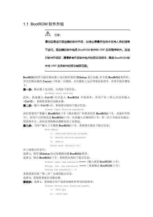
1.1 BootROM软件升级注意:请勿轻易进行路由器的软件升级,如有必要最好在技术支持人员的指导下进行。
路由器的软件包括BootROM软件和VRP主体程序软件。
在进行软件升级时,请请参考升级软件包中的版本说明书,确保BootROM软件与VRP主体软件的版本能够匹配。
BootROM软件只能在路由器上电自检时使用XModem进行加载。
在升级BootROM软件时,首先在路由器的Console口外接一台微机,并在微机上运行终端仿真程序。
具体升级步骤如下:第一步:路由器上电自检,出现如下的信息:Quidway start booting此时,快速键入<Ctrl+D>可以进入BootROM升级菜单,若用户在三秒之内没有输入<Ctrl+D>,系统将重新启动路由器。
第二步:键入<Ctrl+D>后,系统将出现如下提示信息:Please input Bootrom password:此时需要用户要输入BootROM口令(路由器出厂时缺省没有BootROM口令,直接回车即可)。
若用户已经修改过BootROM口令,应该输入正确的的口令,若三次口令验证未通过,则系统中止,此时必须将路由器断电再上电重起。
第三步:当用户输入了正确的BootROM口令,系统将出现如下提示信息:Boot Menu:1: Download Bootrom program2: Modify Bootrom password3: RebootEnter your choice(1-3):在上述提示信息中:选择1:使用XModem协议加载路由器BootROM软件。
选择2:修改BootROM口令,系统将出现如下提示信息:Please input new password:*****(输入新的BootROM口令)Retype the new password: *****(重新确认BootROM口令)Saving the password... #系统重新回到“第三步”出现的提示信息。
- 1、下载文档前请自行甄别文档内容的完整性,平台不提供额外的编辑、内容补充、找答案等附加服务。
- 2、"仅部分预览"的文档,不可在线预览部分如存在完整性等问题,可反馈申请退款(可完整预览的文档不适用该条件!)。
- 3、如文档侵犯您的权益,请联系客服反馈,我们会尽快为您处理(人工客服工作时间:9:00-18:30)。
ISP 上位机及BOOT 更新说明
前言
本篇用户手册为实现ISP 串口、工具及脱机下载。
在方案的生产开发过程中,很多用户需要有一个烧录器,既能实现在线下载也能实现脱机下载,特别是当芯片加密或SWD 下载口被复用后,需要在ISP 模式下修改MCU 内部的Flash ,以恢复SWD 下载功能。
华芯提供一个烧录器和ISP 上位机,不需要复杂的其他功能,接口方面也十分简易,只需要将烧录器的接口与芯片连接正确就能实现PC 端在线下载和MCU 端脱机下载。
通过本文档,您可以了解如何通过华芯的烧录器实现ISP 在线及脱机下载。
本文还提供一个范例供用户参考。
ISP 烧录器连接流程图
ISP 烧录器
SWM 系列芯片
硬件接口连接
ISP 烧录器串口下载
通过ISP 进行串口下载程序只需简单的三线串口(RX 、TX 、GND ),另外,因
ISP 烧录器不带有电源,因此需要在目标板上引出工作电源(也就是说,烧录器的电源由目标板提供,在设计目标板的时候需要考虑引出所需要的电源),一共是4根线:TX 、RX 、Vin (目标上芯片的工作电压)和GND 。
ISP烧录器工具下载
工具下载的硬件连接方式与串口下载类似,但要加上进入BOOT模式所需的GPIO。
也就是说一共需要连接5根线:TX、RX、ISP、Vin(目标芯片的工作电压)和GND。
具体描述参见下表:
①电源电压只需要满足芯片工作电压即可,具体芯片的工作电压可以参考所选MCU的数据手册。
如果想用ISP烧录器下载程序到MCU,建议设计MCU的时候参考下边的原理图来设计最小系统,在此基础上修改URX、UTX、ISP引脚即可。
说明:本文涉及的范例是基于SWM240这款MCU实现的,用户需根据自己选择的MCU 及产品的需求修改自己的DEMO。
ISP烧录器脱机升级
脱机程序升级模式主要是为了下面进行脱机程序下载做准备的,也就是说,您需要先把目标程序下载到烧录器中。
在这种模式下,您需要将烧录器连接PC上即可,不需要将ISP 烧录器连接到芯片。
对ISP烧录器进行程序下载要把烧录器上对应的引脚连接起来,使烧录器进入脱机程序升级模式。
具体连接方式参见下图。
Warning:如果脱机程序升级模式下ISP烧录器下载程序失败,那么下面的脱机程序下载也无法进行。
ISP烧录器脱机下载
ISP烧录器完成脱机升级后,即可进行脱机下载,这个过程不需要连接PC,只需要连接芯片即可。
具体的接线方式参见“ISP烧录器工具下载”。
对目标板上电就可以对芯片进行脱机下载。
ISP上位机操作
根据硬件接口连接好MCU与烧录器后,需要操作ISP上位机进行烧录程序。
本部分主要配合“ISP烧录器工具下载”和“ISP烧录器脱机下载”使用,通过本部分的介绍,希望能让您快速上手,实现程序的在线下载和脱机下载。
并且重点介绍如何将程序下载到华芯的其他MCU上,这样才使得这款ISP下载器具有通用性。
功能实现
首先打开ISP上位机软件,选择对应型号的MCU:
其次,打开目标Hex或者Bin文件,显示文件内容。
备注:ISP上位机支持实时程序修改,您可直接在文件内容中修改程序中的部分数据。
然后,选择相应的下载方式,打开串口,点击握手,运行状态提示”连接成功!”。
备注:不同的ISP模式需要选择对应的下载方式。
在线下载模式选择工具下载,脱机升级模式选择脱机模式。
其次,选择序列号。
说明:序列号是在实际生产中提供用户标记产品批次的一个标志,初始序列号是用户设定。
比如设定为0x10000000,ISP每成功下载一次程序,此序列号自动加一,变为
0x10000001,以此类推。
用户可根据这个序列号区分产品是哪个批次甚至该批次中的第几块烧录。
存放序列号的地址是固定的,偏移量为0x400。
最后,点击一键下载。
运行状态提示“下载完成”。
备注:您也可只进行全部擦除、扇区擦除操作或程序下载操作;脱机下载方式不支持单步操作。
说明:脱机下载的上位机操作步骤与工具下载类似。
状态提示
总结
本文介绍了如何通过ISP烧录器实现程序的在线或脱机下载,可供用户在实际项目中使用。
重要说明-请仔细阅读
华芯微特科技有限公司保留随时对SWM系列MCU或本文档进行变更、更正、增强、修改和改进的权利,恕不另行通知。
买方在选购前应获取关于SWM系列MCU的最新信息。
华芯微特不对任何知识产权进行任何明示或默示的授权或许可。
本文档中的信息取代本文档所有早期版本中提供的信息。
©SYNWIT —保留所有权利。
