GDB DeploymentWorkshop_20090506-07
使用OllyDbg从零开始Cracking 第九章-基本概念
第九章-基本概念本章我们将开始破解。
我们先从基本的概念开始一步步的来介绍破解所需要的步骤。
本次实验依然是我们熟悉的Cruehead`a的CrackMe,但是不要把自己局限于破解这个简单的CrackMe的不同方式-在此过程中,我们将介绍适用于更加复杂的软件的一些标准方法。
让我们用调试器开始破解之旅吧。
通过这个CrackMe我们可以掌握一些基本的概念。
入口点:程序刚刚被加载第一条指令的地址。
为了不和OEP(原始入口点)相混淆,我们稍后再来介绍OEP的概念。
当用OD加载应用程序后,调试器就会停在入口点处,分析代码并且等待用户的进一步提示。
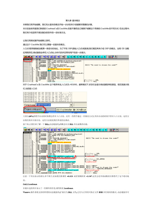
对于Cruehead`a的CrackMe这个程序来说,入口点为401000。
通常情况下,状态栏会显示调试器暂停的原因。
现在就提示我们,当前是入口点:大部分(99%)的程序启动的时候都会停在入口点处。
还有一些程序通过一些修改方式让其在启动的时候不停在入口点处。
这些方法我们将在后面讨论。
这些方法就是我们常说的反调试。
接下来,让我们来了解一下DLL(动态链接库)的概念以及DLL导出函数的功能。
注意一下突出显示的部分,举个例子,比如我们要调用401020或者要跳转到421367,这里会是外部函数的名称替代了这个绝对地址。
CALL LoadIconA在最右边的列中显示了一些额外的信息,调用的是LoadIconA。
Windows操作系统支持的所谓的动态链接库(扩展名为DLL文件),它们与正常的可执行文件EXE具有相同的格式。
动态链接库可导出函数供其他可执行文件(EXE和DLL)调用。
不是在多个可执行文件中有相同的静态副本,而是把功能放置在DLL中。
如果一个功能的代码量很大,那么这样就可以缩减可执行文件的大小,更重要的是可以节省内存。
Windows的基本功能:文件,内存,进程,线程,图形,声音,网络等都是在标准的动态链接库中实现的。
LoadIconA是在User32.dll中实现的一个加载位图的应用程序接口。
展讯 build环境使用手册

展讯 build环境使用手册一、介绍1.1 前言在展讯(Exynos)处理器的开发环境中,build环境是非常重要的一环。
为了保证开发工作的顺利进行,展讯提供了一套完整的build环境使用手册,以帮助开发人员快速搭建和使用展讯的开发环境。
1.2 目的本文旨在介绍展讯build环境的搭建和使用方法,以帮助开发人员快速上手展讯处理器的开发工作。
二、环境搭建2.1 硬件要求在搭建展讯build环境前,首先需要满足一定的硬件要求。
建议使用高性能的计算机,配置至少16GB内存和500GB磁盘空间,以保证编译过程的顺利进行。
2.2 软件要求展讯build环境需要使用特定版本的操作系统和编译工具。
目前推荐使用Ubuntu 18.04 LTS操作系统,并安装必要的开发工具和编译器,如gcc、make等。
2.3 下载代码在搭建build环境之前,需要从展讯官方全球信息湾上下载最新的代码库。
开发人员可以通过Git工具将展讯的开发代码库克隆到本地,并根据需要切换到特定的分支或标签。
2.4 编译工具链展讯build环境需要使用特定的ARM交叉编译工具链,用于编译展讯处理器的应用程序和驱动程序。
开发人员可以从展讯官方全球信息湾上下载最新的编译工具链,并按照官方文档进行安装和配置。
2.5 系统配置在搭建build环境后,还需要进行一些系统配置工作,如设置环境变量、安装必要的依赖库等。
展讯官方文档中提供了详细的配置方法,开发人员可以根据文档进行操作。
三、使用方法3.1 编译应用程序一旦搭建好build环境,开发人员就可以开始编译展讯处理器的应用程序了。
通过使用展讯提供的Makefile和编译工具链,开发人员可以很方便地将自己的应用程序编译成可执行文件,并在展讯处理器上运行。
3.2 编译内核除了应用程序外,展讯的build环境还可以用于编译展讯处理器的内核。
开发人员可以从展讯官方全球信息湾上下载最新的内核代码,并使用展讯提供的配置文件和编译工具链进行内核的编译和定制。
戴尔OpenManage部署工具包安装指南说明书

Dell OpenManage Deployment Toolkit Installation GuideNotes and CautionsNOTE: A NOTE indicates important information that helps you make better use of your computer.____________________Information in this publication is subject to change without notice.© 2012 Dell Inc. All rights reserved.Reproduction of these materials in any manner whatsoever without the written permission of Dell Inc. is strictly forbidden.Trademarks used in this text: Dell™ and OpenManage™, are trademarks of Dell Inc. Red Hat Enterprise Linux® and Enterprise Linux® are registered trademarks of Red Hat, Inc. in the United States and/or other countries. SUSE ™ is a trademark of Novell Inc. in the United States and other countries. Microsoft®, Windows®, Windows Vista® and Windows® 7 are either trademarks or registered trademarks of Microsoft Corporation in the United States and/or other countries. Linux®is a registered trademark of Linus Torvalds.Other trademarks and trade names may be used in this publication to refer to either the entities claiming the marks and names or their products. Dell Inc. disclaims any proprietary interest in trademarks and trade names other than its own.2012 – 02IntroductionThe Dell OpenManage Deployment Toolkit (DTK) includes a set of utilities, sample scripts, and sample configuration files that you need, to deploy and configure your Dell system. Y ou can use DTK to build script-based and RPM-based installation for deploying large number of systems on apre-operating system environment in a reliable way, without changing their current deployment processes.Documents You Will Need•Dell OpenManage Deployment T oolkit Command Line Interface Reference Guide•Dell OpenManage Deployment T oolkit User’s Guide•Operating system documentationFor a complete list of supported operating systems, BIOS firmware, and hardware, see the Dell Systems Software Support Matrix available at /manuals→Software→Systems Management→Dell OpenManage Releases. Click the appropriate product version to access the Support Matrix.PrerequisitesBefore using DTK to deploy Microsoft Windows Pre-installation Environment (PE) or embedded Linux environment (Red Hat Enterprise Linux or SUSE Linux Enterprise Server), ensure you have the following prerequisites:Table 1-1.Prerequisites for InstallationWindows PE Environment Embedded Linux EnvironmentThe DTK self-extracting zip file (DTKX.X-WINPE-XX.exe) available at .The DTK ISO image available at .A Windows workstation that has at least 512 MB of RAM.A workstation that has at least 512 MB of RAM.Quick Installation Guide3Deployment OverviewDTK offers a complete set of utilities, sample scripts, and RPM packages that can be used to automate the deployment of Dell systems.Before running the deployment, ensure that you create specific deployment media to facilitate the deployment method you choose. For more information, see the Dell OpenManage Deployment T oolkit User’s Guide available on /manuals→Software→Systems Management→Dell OpenManage Deployment Toolkit.Deployment PrerequisitesBefore beginning the deployment process for Windows PE, ensure that you have all of the following tools, software, and information ready to use or consult:•Windows Automated Installation Kit (AIK) 1.1 released with Microsoft Windows Vista SP1 and Windows Server 2008 to build Windows PE 2.0.•Windows AIK for Windows 7 to build Windows PE 3.0.•An unzip utility.•Working knowledge to build Windows PE 2.0 and Windows PE 3.0 (See the Microsoft documentation to customize Windows PE).•Working knowledge of Microsoft Remote Installation Services (RIS) and Automated Deployment Services (ADS) (including setting up of RIS and ADS environments) or any other third party deployment system or tool for Windows PE.•Working knowledge of Windows Deployment Services (WDS) or any other third party deployment system or tool for Windows PE.• A workstation with the following capabilities:–Writable media drive–Network access• A target system with a media drive, if performing a local deployment.• A target system with a media drive and network access, if performing a network deployment.•All DTK utilities, sample scripts, and sample configuration files.•Dell Systems Management Tools and Documentation DVD.4Quick Installation GuideQuick Installation Guide 5•Y our operating system software and documentation.•An optimally configured source system with network access. NOTE: You can also download the latest drivers from .For embedded Linux, ensure that you have all of the following tools, software, and information ready to use or consult:•Advanced knowledge of Linux and Linux scripting (bash), Linux networking, installing and working with RPM Package Managers (RPMs), and creating and modifying loop file systems.•Any third party deployment system or tool.• A workstation with the following capabilities:–A writable media drive –Network access •A target system with a media drive, if performing a local deployment.•A target system with a media drive and network access, if performing a network deployment.•All DTK utilities, sample scripts, sample configuration files, and RPM packages.•All operating system RPM packages that DTK RPMs require.NOTE: Tools such as Yellowdog Updater Modified (YUM), Yet Another Setup Tool (YAST), and Advanced Packaging Tool (APT) can be used to manage RPM dependency issues.•All other utilities and files necessary to perform the deployment, including all required Linux drivers, operating system drivers, and the Dell utility partition file.•Dell Systems Management Tools and Documentation DVD.•Y our operating system software and documentation.•An optimally configured source system with network access.NOTE: You can download the latest drivers from .6Quick Installation GuidePreparing for DeploymentIf you are using the Windows PE environment:1Copy or extract DTK utilities, sample scripts, sample configuration files, and drivers provided (in the zip file) to the Windows PE image.2Organize DTK utilities, script files, configuration files, the operating system installation files, and the requisite system files and drivers on a network share or local media.3Set up a Source System by using the Dell Systems Build and Update Utility (to install your operating system) and the Systems Service and Diagnostics Tools (to load drivers). The Source System acts as a masterserver that is used to replicate settings to the T argetServers .NOTE: You can also download the latest drivers from the Dell Support website at .4Generate a system BIOS, BMC, RAID, and/or RAC configuration profile from the Source System . Copy the generated configuration files to a read/write share on the workstation or server.NOTE: You can obtain the system BIOS, BMC, RAID, and/or RAC configuration files by booting from DTK Windows PE image and running the SYSCAP .BAT , RAIDCAP .BAT , and RACCAP .BAT scripts. 5Create an operating system answer file that contains unattended operating system software installation information.6Edit DTK sample script files that access the system configuration files to set up the system BIOS, BMC, RAID, and RAC and then, install an operating system on a Target Server .If you are using the embedded Linux environment:1Obtain the DTK Linux ISO image, which is a self-contained bootable ISO image.2Use and customize the sample scripts as per your requirements.3Set up a Source System by using the Systems Build and Update Utility on the Dell Systems Management T ools and Documentation DVD (to install your operating system) and the Systems Service and Diagnostics Tools (to load drivers).NOTE: You can also download the latest drivers from the Dell Support website at .4Generate a system BIOS, BMC, RAID, and/or RAC configuration profile from the optimally configured source system. Copy the generatedconfiguration files to a read/write share onto the workstation or server.NOTE: You can obtain the system BIOS, BMC, RAID, and/or RAC configurationfiles by booting from DTK Linux ISO image and running the syscap.sh,raidcap.sh, and raccap.sh scripts.5Create an operating system answer file that contains unattended operating system software installation information.6Install an operating system on a T arget Server.DeployingTo proceed with deployment, ensure that you have prepared all scripts, files, and utilities. Y ou can deploy the Win PE and embedded Linux using one of the following methods:•Deploy using removable boot media with a network connection (media-based)•Deploy using removable boot media without a network connection (media-based)•Network-based deployment (remote)For information on these methods, see the Dell OpenManage DeploymentT oolkit User’s Guide available on /manuals→Software→Systems Management→Dell OpenManage Deployment Toolkit.Upgrading Your DTK VersionWhen upgrading from a previous release of DTK, ensure that you create the environment for new DTK version separately from the previous version. This step is necessary because the environments and requirements for the new DTK versions are completely different.Quick Installation Guide78Quick Installation Guide。
IAR_使用最全方法

软件介绍AVR?IAREmbeddedWorkbench?IDE用户手册的这部分包括以下章节:✍✍✍产品介绍✍✍✍已安装文件1.1产品介绍嵌入式IAREmbeddedWorkbench?是一个非常有效的集成开发环境(IDE),它使用户充分有效有效提一个可扩展的模块化的环境尽管嵌入式IAREmbeddedWorkbenchIDE可以提供完成一个成功工程所需的所有工具,但我们也认识到集成其他工具的必要性。
因此,IAREmbeddedWorkbenchIDE容易适应于用户喜欢的编辑器和源代码控制系统。
IARXLINKLinker可以输出多种格式,使用户可在第三方的软件上进行调试。
实时操作系统(RTOS)支持也可加载到产品中。
编译器,汇编器和连接器也可在命令行环境中运行,用户可以在一个已建好的工程环境中把它们作为外部工具使用。
特性嵌入式IAREmbeddedWorkbench是一个灵活的集成开发环境,使用户可以针对多种不同的目标处理器开发应用程序。
并为快速开发和调试提供便捷的Windows截面。
++源窗口管理为使用户充分而方便地控制窗口的位置,每个窗口都可停靠,用户就可以有选择地给窗口做上标记。
可停靠的窗口系统还通过一种节省空间方式使多个窗口可同时打开。
另外,重新分配窗口大小也很方便。
2文本编辑器集成化的文本编辑器可以并行编辑多个文件,并具有时兴编辑器所期望的所有编辑特性,包括无限次的撤销/重做和自动完成。
另外它还包含针对软件开发的特殊功能,比如关键字的着色(C/C++,汇编和用户定义等)、段缩进、以及对源文件的导航功能。
还可识别C语言元素(例如括号的匹配问题)。
下表指出另外的一些特性:✍✍✍上下文智能帮助系统可以显示DLIB库的参考信息;✍✍✍使用文本风格和色条指出C、C++和汇编程序的语法;✍✍✍强大的搜索和置换功能,包括多文件搜索;驱动C-SPY 驱动的概述,请参见第8页,IARC-SPY调试器系统。
Klocwork培训手册K9.1

1. 软件安装 ................................................................................................................................... 1
2 启动和停止服务 ........................................................................................................................ 7
2.1 启动所有服务 ......................................................................................................................... 7 2.2 查看服务状态 ......................................................................................................................... 7 2.3 停止所有服务 ......................................................................................................................... 7 2.4 启动单个服务 ......................................................................................................................... 7 2.5 停止单个服务 ......................................................................................................................... 7 2.6 问题与解决 ............................................................................................................................. 8
BEA WebLogic Workshop 8.1 快速上手指南

BEA WebLogic Workshop 8.1 ® 快速上手指南開始使用BEA WebLogic Workshop 8.1™台灣比爾亞系統台北市敦化南路二段105號23F電話: (02) 27841623傳真: (02) 278416252003年7月BEA WebLogic Workshop™版權宣告比爾亞系統公司版權所有,出版於2003年7月1日(版本1.1)使用權利說明非經比爾亞系統公司(BEA Systems, Inc)同意,不得擅自使用電子媒介或設備,將本文全文或部分影印、重製、翻譯或刪除。
本文所有資訊若有所更動將不另行通知,且不列入比爾亞系統(BEA System)保證的一環。
更進一步,比爾亞系統不保證本文章所提供的內容及解釋名詞完整無誤,若有誤概不負責。
商標及服務標記BEA、WebLogic和Tuxedo是比爾亞系統公司(BEA Systems, Inc)註冊商標。
BEA WebLogicE-Business Platform、BEA E-Business Control Center、BEA Campaign Manager forWebLogic、BEA WebLogic Commerce Server、BEA WebLogic Personalization Server、BEAWebLogic Portal、BEA eLink、BEA WebLogic Integration、BEA WebLogic Server、BEAWebLogic Workshop以及BEA WebLogic Enterprise皆為比爾亞系統公司(BEA Systems, Inc)的商標。
尚未列出的商標仍屬於比爾亞系統公司所有。
BEA WebLogic Workshop 8.1 ™快速上手指南第 2 頁目錄表版權宣告 (2)如何使用這份指南 (4)額外的教育資源 (4)更多的資訊、資料表、產品手冊 (4)評估軟體 (4)新聞稿 (4)開發者資源 (4)BEA WEBLOGIC WORKSHOP 8.1產品概述 (5)視覺化開發環境 (5)執行期框架 (7)J AVA 控制項 (9)BEA W EB L OGIC W ORKSHOP 8.1之應用程式型別 (10)BEA WEBLOGIC WORKSHOP 8.1 快速上手範例 (12)安裝BEA W EB L OGIC W ORKSHOP (12)快速上手範例情境-A VITEK E LECTRONICS公司 (13)一步步體驗BEA W EB L OGIC W ORKSHOP (14)範例 #1. 導覽與設定範例資料 (15)視覺化開發環境 (16)自動部署 (17)範例 #2. 建立一個客制化的控制項 (18)內建的J AVA 控制項 (18)客製J AVA 控制項 (19)非同步作業控制項 (23)範例 #3. 新建企業級的網路服務 (26)支援非同步W EB S ERVICES (27)自動化部署與測試 (29)鬆散耦合 (32)範例 #4. 建置企業層級的網站應用程式 (38)J AVA P AGE F LOW 技術 (38)自動化的資料繫結 (43)自動化的部署與測試 (46)範例#5:用JAVA 控制項方式建立網頁應用程式 (50)範例 #6: 使用XMLBEANS來處理JAVA中的XML (55)BEA WEBLOGIC WORKSHOP 8.1背後的奧妙 (58)結語 (59)附錄:BEA WEBLOGIC WORKSHOP 8.1 規格需求 (60)進階:產品資訊和開發資源 (60)如何使用這份指南這份快速上手指南帶來一些當您準備探索和評估BEA WebLogic Workshop 8.1 ™可能是有用的重要題材。
XI教程 Part6 RWB

(decentral) J2SE Adapter Adapter Engine Engine
Adapter Engine
© SAP AG 2004, Runtime Workbench 7
The Runtime Workbench Performance Analysis Tool shows performance statistics for user-defined selection criteria. Allows to see the latency as well as the throughput. This is important for ongoing sizing of the XI.
Adapter Engine
© SAP AG 2004, Runtime Workbench 5
Message monitoring can be used to find and diagnose errors with specific XI messages. Capabilities are similar to transaction SXI_MONITOR. The message monitoring infrastructure is also used by the end-to-end monitor. Of course, message monitoring is only available for asynchronous messages, unless the XI Pipeline is configured to persist synchronous (Best Effort) messages.
System Landscape Directory
IBM CICS Deployment Assistant for z OS 5.1 用户指南说明书

®
IBM CICS Deployment Assistant for z/OS, Version 5.1
Recent enhancements Support for CICS® Transaction Server V5.1 Enriched discovery of over 30 entities Improved visualization with tagging and filtering Connections view with scoping Export model for external reporting CICS TS V5.1 upgrade cheat sheet Tagging and filtering of model elements New navigators JCL improvements IPv6 support Virtual IP addressing support Serviceability enhancements
Discovered CICS regions and other entities in the model can be used to visualize the CICS environment more effectively.
CICS DA can clone existing CICS regions by creating and submitting the necessary JCL, startup options, datasets, and resource definitions.
Filtering
芯片失效分析系统Avalon软件系统说明书
DATASHEET Overview Avalon software system is the next-generation CAD navigation standard for failure analysis, design debug and low-yield analysis. Avalon is a power packed product with tools, features, options and networking capability that provides a complete system for fast, efficient and accurate investigation of inspection, test and analysis jobs. Avalon optimizes the equipment and personnel resources of design and semiconductor failure analysis (FA) labs by providing an easy-to-use software interface and navigation capabilities for almost every type of test and analytical failure analysis equipment.Avalon enables closer collaboration of product and design groups with FA labs, dramatically improving time to yield and market. Avalon can import CAD design data from all key design tools and several user-proprietary formats while providing visual representations of circuits that can be annotated, exploded, searched and linked with ease.Benefits • Improves failure analysis productivity through a common software platform for various FA equipment • Significantly decreases time to market with reduced FA cycle time • Faster problem solving by cross-mapping between device nodes to view all three design domains (layout, netlist and schematic) simultaneously • Increases accuracy of FA root cause analysis using advanced debug tools • Single application that overlays images from various FA equipment on to design layout • Secure access to all FA information using KDB™ database • Design independent system that supports all major layout versus schematic (LVS)• Complete access to all debug tools critical to failure trace, circuit debug and killer defect source analysis • Simple deployment setup with support for Linux and Windows • Seamless integration with legacy Camelot™ and Merlin™ databases • Ease of conversion for layout, netlist and schematic data and establishes cross-mapping links between each data entityCAD Navigation andDebug Solutions forFailure AnalysisAvalonFigure 1: Avalon CAD-navigation system integrating layout, signal tracing and 3D viewSupporting all CAD Design DataSynopsys is committed to being the leading provider of software solutions that links all CAD design data. Avalon is a comprehensive package that reads all EDA tools and design data from verification systems and several user-proprietary formats. The KDB™database is designed to interface with all key design formats.Today, there are more EDA developers and more verification package choices; Synopsys is the only company thatsupports all of them.• LVS Conversions: Cadence (Assura, DIVA), Mentor Graphics (CheckMate, Calibre), Synopsys (Hercules, ICV)• Netlist Conversion: SPICE, EDIF, OpenAccess• Layout Conversion: GDSII, OASIS®The highest priorities for Avalon users are faster data accessibility, support diverse failure analysis equipment and availability of debug tools. Avalon provides the optimal solution for both small and continually-expanding FA labs and design debug teams. The Avalon database is design independent and offers a superior level of data consistency and security. The unique design of the internal database schema guarantees compatibility with decades-old databases. This is an indispensable feature for all failure analysis, QAand manufacturing organizations especially in the automotive industry.Figure 2: Avalon SchemView and NetView provide an easy way to navigate inside circuit schematicsProviding Critical Analysis FunctionsIn addition to its CAD navigation and database capabilities, Avalon’s analysis features have become indispensable to the FA lab. Different viewing options are critical in tracking potential failures and determining the source and origin of killer defects. Avalon includes special schematic capabilities and layout features that are invaluable to FA engineers as they debug chips manufactured using new processes.Avalon View Only Client consists of maskview, netview, schemview, i-schemview, K-EDIT, defect wafermap and 3D-SAA. The list below details some of the most commonly used applications.Defect Wafer Map integrates defect inspection data with the device CAD design using the defect coordinates to navigate an equipment stage and pinpoint the defect for closer inspection and characterization. Avalon sorts defects by size, location or class, as well as layout location and allows the user to define custom wafer maps. Additionally, users can classify defects, attach images and write updated information to the defect files.Figure 3: Defect Wafer Map pinpoints defects for closer inspectionSchemView provides tracking of potential failures through visualization of the chip logic. Cross-mapping of nets and instances to the device layout and netlist, SchemView helps determine the source and origin of chip failures. SchemView helps determine the source and origin of chip failures. The entire design is displayed in cell hierarchy format, allowing push-down to a transistor level.Figure 4: K-Edit allows collaboration between design, fab and labI-Schem (Interactive Schematic) creates a schematic from a netlist in a net-oriented format allowing forward and backward tracking to locate a fault. Features like Add Driver or Add Input Cone allow for quick analysis and verification of diagnostic resultsin scan chains.Figure 5: I-Schem creates a schematic from a netlistK-Bitmap allows equipment CAD navigation when analyzing memory chips by identifying the physical location of failingmemory cells. It eliminates tedious screen counting by converting the logical addresses, or row and column coordinates, to thephysical location.Figure 6: K-Bitmap identifies the physical location of bit addresses in memory devices3D Small-Area Analysis provides a three-dimensional cross- section capability to FA engineers, enabling faster localization of circuit failures to accelerate IC manufacturing yield improvement.Figure 7: 3D Small-Area Analysis enables faster localization of circuit failuresHot-Spot Analyzer allows user to draw regions on the layout that correspond to hot-spot regions (emission spots) to detect the crucial nets. It finds the nets in each hot-spot region and plots a pareto graph of nets crossing one or more hotspots which helps to easily locate the killer net.Figure 8: Hot-Spot Analyzer displays number of nets in a hot spotUser-Defined Online Search (UDOS) allows users to search a small area of a die for unique polygon features, repeated features or lack of features. Applications include, but are not limited to, FIB-able regions, repeaters, pattern fidelity and lithographic applications.Figure 9: User-Defined Online Search (UDOS) finds easy-to-access tracesPassive Voltage Contrast Checker (PVC) quickly and accurately validates the integrity of a circuit’s conductivity and provides detailed information for identifying suspect faults at via or metal tracesFigure 10: Passive Voltage Contrast (PVC) Checker identifies suspect vias or metal tracesElectronic Virtual Layer marks objects to represent net connectivity during a FIB deposit or cut using KEdit. The online trace will simulate the new connectivity to the virtual layer. PVC checker could be used on this virtual layer to simulate the crack or short.Check Adjacent Nets allows logical analysis of nets. This command line tool finds the adjacent nets which are within user-specified threshold distance to find shorts.Export Partial Layout enables the customer to share partial layout data with service labs without compromising the IP of the product.Image Mapper automates the image alignment process in Avalon Maskview and saves a lot of time and effort spent inmanual alignment.Advanced 3D Viewer displays real time 3D view of the selected layout area. It shows each process step in the 3D view for which it uses the process data along with design data. It zooms into smaller details and helps to minimize unintended consequences during FIB cuts due to underneath high density structure.Avalon SolutionAvalon brings all the advantages of enterprise-wide computing for FA of the chip. Avalon is an open architecture system that connects users over local and wide area networks for seamless integration and database sharing. Instrument integration throughout the fab and other locations throughout the enterprise enables viewing, modifying, characterizing and testing the same wafer location with different instruments, or the same location on wafers at different facilities using the same chip design.Figure 11: Avalon’s open architecture integrates with Synopsys’ Yield ExplorerIC DesignToolsFigure 12: Avalon server solutionComprehensive Library of FA Tool DriversAvalon provides navigation with almost every equipment used in the FA lab. With a continued commitment to support drivers for all types of test and analysis equipment, Synopsys will continue to develop driver interfaces for new tools as they are introduced to the market, as well as the next generation of existing tools.Equipment Supported by Avalon• Analytical Probe Stations• Atomic Force Microscopes• E-Beam Probers• IR Imaging• Mechanical Stage Controllers• Emission Microscopes• Microanalysis Systems• FIB Workstation• Laser Voltage Probe• LSM• EDA LVS• Microchemical Lasers• OBIC Instruments• Optical Review• SEM Tools• Photon Emission Microscopes• Laser Scan Microscopes©2018 Synopsys, Inc. All rights reserved. Synopsys is a trademark of Synopsys, Inc. in the United States and other countries. A list of Synopsys trademarks isavailable at /copyright.html . All other names mentioned herein are trademarks or registered trademarks of their respective owners.。
Windows Server 2012 R2 快速入门指南.pdf_1701126129.32377
Step 3
Deploy Windows Server 2012
Microsoft Deployment Toolkit Microsoft Deployment Toolkit (MDT) 2012 provides guidance and tools to help you quickly deploy Windows Server 2012. You can use MDT to create completely functional base servers that are ready for provisioning across an organization. You can also customize the MDT deployment process to install line-of-business applications for Windows Server 2003, Windows Server 2008, and Windows Server 2012.
--Remote Desktop Connection Broker --Remote Desktop Licensing --Remote Desktop Virtualization Host • Routing and Remote Access Server • Web Server (Internet Information Services including a subset of ) • Windows Server Update Services
NOTE: You can switch between the Server Core option and the Server with a GUI option as needed at any time later.
GDB使用说明

GDB使用说明GDB使用说明1、简介GDB(GNU调试器)是一个功能强大的开源调试工具,用于调试C、C++、Fortran等编程语言的程序。
本文档将提供详细的GDB使用说明,包括安装、启动、基本命令以及高级功能的介绍。
2、安装a) 在Linux上安装GDB:在终端中运行以下命令安装GDB:```sudo apt-get install gdb```b) 在Windows上安装GDB:从GDB官方网站最新的Windows 安装包,并按照安装向导进行安装。
3、启动GDBa) 在Linux上启动GDB:在终端中运行以下命令启动GDB:```gdb [可执行文件名]```b) 在Windows上启动GDB:在命令提示符中切换到GDB的安装目录,然后执行以下命令启动GDB:```gdb:exe [可执行文件名]```4、基本命令a) 运行程序- `run`:开始执行程序。
- `r`:运行程序的简写形式。
b) 设置断点- `break [行号]`:在指定行号设置断点。
- `b [行号]`:设置断点的简写形式。
- `break [函数名]`:在指定函数设置断点。
- `b [函数名]`:设置断点的简写形式。
c) 单步执行- `next`:执行下一行语句。
- `n`:`next`命令的简写形式。
- `step`:进入函数内部执行。
- `s`:`step`命令的简写形式。
d) 打印变量- `print [变量名]`:打印指定变量的值。
- `p [变量名]`:`print`命令的简写形式。
e) 查看栈信息- `bt`:查看完整的栈回溯信息。
- `backtrace`:`bt`命令的完整形式。
f) 调试多线程程序- `info threads`:查看线程信息。
- `thread [线程号]`:切换到指定线程。
5、高级功能a) 控制程序的执行- `continue`:从当前位置继续执行程序。
- `c`:`continue`命令的简写形式。
宝兰德软件 BES Application Server Cluster 安装手册说明书
BES Application Server Cluster安装手册V9.5北京宝兰德软件股份有限公司Beijing Baolande Software Corporation版权所有侵权必究All rights reserved前言本文档是BES Application Server Cluster的安装手册,详细介绍如何在多种平台上安装BES Application Server Cluster。
本手册适合的对象本手册主要适用于使用BES Application Server Cluster的系统管理员和基于其所管理的服务器进行Java应用开发的应用开发人员。
本手册假定您已经具备如下技能:1、操作系统的基础操作。
2、JDK的安装。
约定BES Application Server Cluster定义了一些变量来表示BES Application Server Cluster目录等信息,本文档中涉及到的有:表 BES Application Server Cluster变量说明产品文档集BES Application Server Cluster提供的文档集包括:1.快速开始手册:简单介绍BES Application Server Cluster的安装和基本使用。
2.安装手册:详细介绍如何在各个操作系统上安装BES Application ServerCluster,以及产品的注册过程。
3.用户手册:详细介绍BES Application Server Cluster的配置和管理。
技术支持BES Application Server Cluster提供全方位的技术支持,获得技术支持的方式有:网址:Support Email:*********************Support Tel:400 650 1976在取得技术支持时,请提供如下信息:1.姓名2.公司信息及联系方式3.操作系统及其版本4.BES Application Server Cluster版本5.问题或错误相关的详细日志信息目录第1章产品介绍 (1)1.1关于BES A PPLICATION S ERVER C LUSTER (1)1.2产品特性 (1)1.3支持的平台环境 (1)1.4产品体系结构 (3)1.4.1 松耦合集群体系架构 (3)1.4.2 应用服务器实例体系结构 (4)第2章产品安装 (5)2.1安装前准备 (5)2.1.1 获取安装包 (5)2.1.2 系统需求 (5)2.1.3 安装前检查 (6)2.2安装程序安装步骤 (6)2.2.1 安装程序介绍 (6)2.2.1.1 GUI方式 (6)2.2.1.2 静默方式 (13)2.2.1.3 命令行方式 (14)2.2.2 安装日志 (14)2.3解压版安装步骤 (15)2.3.1 解压产品安装包 (15)2.3.2 启动 (15)2.3.3 登录 (15)第3章产品注册 (16)第4章产品的启动和停止 (17)4.1启动并访问管理中心控制台 (17)4.2安装并启停节点 (17)4.3注册服务/删除服务 (18)4.4操作应用服务器实例 (18)4.5停止管理中心控制台 (18)第5章产品卸载 (19)5.1安装版产品卸载 (19)5.2解压版产品卸载 (19)第6章常见问题解答 (20)第1章产品介绍1.1 关于BES Application Server ClusterBES Application Server Cluster是节点、集群、实例管理平台,实现了节点和实例的跨平台管理。
deployment创建过程
deployment创建过程Deployment是指在软件开发完成后将软件部署到服务器或者其他设备上,让软件可以被用户使用。
对于一个软件项目来说,deployment创建过程是非常重要的一步。
本文将从准备工作、部署方式、自动化部署三个角度来介绍deployment的创建过程。
一、准备工作在进行deployment创建之前,我们需要进行一些准备工作。
首先,我们需要将代码上传到代码管理平台,如GitHub、GitLab、Bitbucket 等。
其次,我们需要为项目配置一个CI/CD工具,如Jenkins、TravisCI、GitLab CI等。
最后,我们需要为项目选取云服务提供商,如AWS、Azure、Google Cloud等。
二、部署方式在选择部署方式的时候,我们需要根据项目的具体情况进行选择,以下列出一些比较常见的部署方式:1. 传统部署:将打包好的代码上传到服务器,然后通过命令行启动服务。
2. 容器化部署:使用Docker等容器化技术将项目打包成一个镜像,并通过容器管理工具Kubernetes等进行部署和管理。
3. Serverless部署:使用Function as a Service(FaaS),将应用程序代码和相关的配置和资源文件打包成zip文件,上传到云服务中,如AWS Lambda、Azure Functions等。
三、自动化部署手动部署可能会出现人为错误,而自动化部署可以减少这些错误的出现。
下面简单介绍一下Jenkins的自动化部署流程:1. 添加构建任务:在Jenkins的主页创建一个新的构建任务,并选择好源码仓库、构建触发器和构建步骤。
2. 配置构建步骤:根据项目的具体情况,选择构建步骤,并配置好相关的参数。
构建步骤包括构建工程、单元测试、生成构建报告、上传构建物等操作。
3. 设置自动化部署:在构建成功后,自动将构建物部署到目标服务器上。
可以使用SCP、SSH、Ansible等工具来实现。
web应用部署teamcenter
1.1.1 web应用部署1.1.1.1 安装服务应用管理器(web application manager)1)首先需要安装Java 运行环境(JRE),运行JRE安装文件2)点击<安装>按钮:3)安装完成:4)把Java bin路径添加到path环境变量下:右键我的电脑->属性->高级->环境变量,选择系统变量中的path变量并双击,在现有变量值之前加上Java bin 的路径以及“;”(注意为半角):点击编辑系统变量窗口中的<确定>按钮;点击环境变量窗口的<确定>按钮;点击系统属性窗口的<确定>按钮;5)安装web应用管理器(Web Application Manager):从Teamcenter8的安装文件中找到Web_tier文件夹;6)双击INSTALL_TCWEB.EXE,在解压文件夹对话框中,为INSTALL_TCWEB.EXE指定解压路径:C:\Teamcenter8\Web_tier7)解压成功:8)结果:web应用管理器已经安装到路径C:\Teamcenter8\Web_tier下,在该目录下,能看到一个叫insweb.bat的文档,它用来启动web应用管理器;1.1.1.2 Web应用服务器1)双击insweb.bat,启动web应用管理器,打开Teamcenter Web应用程序管理器:2)单击<复制ICD>按钮,打开复制ICD文件对话框:3)单击<浏览>按钮,导航到TC8安装文件下的Web_tier路径下的icd:4)单击<确定>按钮,打开进度对话框:5)当ICD文件复制完成后,待进度对话框显示”单击“确定”继续”后,单击<确定>按钮:6)此时<添加>按钮激活,单击<添加>按钮,打开添加Web应用程序窗口:7)在名称栏输入Teamcenter Web Tier,在登台位置栏输入C:\Siemens(TC8安装路径)\web_tier\web_tier_staging;8)点击高级Web应用程序选项,打开高级Web应用程序选项对话框:注意到可部署的文件名为tc,这将在用户访问瘦客户端的URL中用到;9)单击高级Web应用程序选项对话框中的<确定>按钮;10)返回添加Web应用程序窗口,在安装映像磁盘位置部分,单击<添加>按钮,打开添加磁盘位置对话框:11)单击<浏览>按钮,导航到TC8安装文件下的Web_tier:12)单击<确定>按钮,这时可以发现添加Web应用程序窗口中解决方案类型中有且只有瘦客户端一个解决方案类型,这是因为刚才仅复制了瘦客户端的ICD文件;13)单击<解决方案>按钮,打开选择解决方案窗口,这时可以发现已经选择了如下两个解决方案:Teamcenter-Web Tier Infrastructure 和Teamcenter-Web Tier Core Applications;另外添加勾选Teamcenter-Server Adapter;14)单击<确定>按钮,返回添加Web应用程序窗口,单击<确定>按钮,打开修改所需的关联参数:设置所需修改的参数:TreeCache Peers值改为TC服务器名pdmappsvr[17800],TcLocale值从下拉框中选择zh_CN;15)单击<确定>按钮,打开进度对话框,待进度对话框显示”单击“确定”继续”后,单击<确定>按钮;16)退出web 应用管理器。
opengauss5.0企业版主备安装

opengauss5.0企业版主备安装作者:JQKA知乎:月亮岛岛主1、基础环境硬件配置:cpu:2c 2uMem:4GVM workstation 虚拟化8g 4c 2台数据库:openGauss-5.0.0-CentOS-64bit-all.tar.gz操作系统:CentOS-7-x86_64-DVD-1810.isoNode1:192.168.92.161Node2:192.168.92.1622、系统环境设置关闭防火墙systemctl stop firewalld.service #关闭防火墙systemctl disable firewalld.service安装前检查软件环境如果是最小化安装centos7.6,需要安装额外的软件yum install net-tools.x86_64 -y # 没有ifconfig命令需要安装该软件yum install -y epel-release # 安装当yum显示没有可用软件包的时候,代表在linux系统yum 源中已经没有对应的安装包了,这时,我们需要安装EPEL。
EPEL(Extra Packages for Enterprise Linux),企业版Linux额外包,RHEL分布非标准包的社区类库。
yum updateyum install -y bzip2 # 安装bzip2用于后面的解压openGauss安装包安装python3.6python -V结果是python2安装python3yum install -y python3验证python版本[root@node1 ~]# python -VPython 2.7.5[root@node1 ~]# python3 -VPython 3.6.8软件依赖要求yum list libaio-develyum list flexyum list bisonyum list ncurses-develyum list glibc-develyum list patchyum list redhat-lsb-coreyum list readline-devel所需软件建议版本libaio-devel建议版本:0.3.109-13flex要求版本:2.5.31 以上bison建议版本:2.7-4ncurses-devel建议版本:5.9-13.20130511 glibc-devel建议版本:2.17-111patch建议版本:2.7.1-10 redhat-lsb-core建议版本:4.1readline-devel建议版本:7.0-13libnsl(openEuler+x86环境中)建议版本:2.28-36关闭SELINUX,将值改成disabled[root@node1 ~]# vi /etc/selinux/config[root@node1 ~]# cat /etc/selinux/config# This file controls the state of SELinux on the system.# SELINUX= can take one of these three values:# enforcing - SELinux security policy is enforced.# permissive - SELinux prints warnings instead of enforcing.# disabled - No SELinux policy is loaded.SELINUX=disabled# SELINUXTYPE= can take one of three values:# targeted - Targeted processes are protected,# minimum - Modification of targeted policy. Only selected processes are protected. # mls - Multi Level Security protection.SELINUXTYPE=targeted设置时区和时间cp /usr/share/zoneinfo/Asia/Shanghai /etc/localtime如果出现情况,说明时区正常,可跳过设置字符集参数[root@node1 ~]# cat /etc/locale.confLANG="en_US.UTF-8"其他小配置(可选)修改mtu值[root@node1 ~]# ifconfig ens33 mtu 8192此命令只能临时修改,永久修改如下# vi /etc/sysconfig/network-scripts/ifcfg-ens33#增加如下内容MTU="8192"[root@node1 ~]# ifconfigens33: flags=4163<UP,BROADCAST,RUNNING,MULTICAST> mtu 8192inet 192.168.92.137 netmask 255.255.255.0 broadcast 192.168.92.255inet6 fe80::68e7:6a06:fcd1:6efa prefixlen 64 scopeid 0x20<link>ether 00:0c:29:ec:c3:36 txqueuelen 1000 (Ethernet)RX packets 1587 bytes 126990 (124.0 KiB)RX errors 0 dropped 0 overruns 0 frame 0TX packets 1032 bytes 173388 (169.3 KiB)TX errors 0 dropped 0 overruns 0 carrier 0 collisions 0# vi /etc/sysconfig/network-scripts/ifcfg-eth0#增加如下内容MTU="8192"允许root用户远程登陆:vim /etc/ssh/sshd_config将“PermitRootLogin yes”前面的#号去掉让配置生效修改Banner配置cat >>/etc/ssh/sshd_config<<EOFBanner noneEOF# 检查cat /etc/ssh/sshd_config | grep Banner# 重启生效systemctl restart sshd.service创建dbgrp组和用户ommgroupadd dbgrpuseradd -g dbgrp omm # 可后面安装时创建passwd omm #设置密码为Gauss_1234(注意大小写)chown -R omm:dbgrp /opengauss修改/etc/hostsvi /etc/hosts192.168.92.161 node1 192.168.92.162 node2手工建立互信# root配置互信ssh-keygen -t rsassh-copy-id node1ssh-copy-id node2#omm配置互信su - ommssh-keygen -t rsa ssh-copy-id node1 ssh-copy-id node2重启操作系统3、安装openGauss上传安装包文件至/opengauss 并解压mkdir -p /opengausscd /opengauss/tar -zxvf openGauss-5.0.0-CentOS-64bit-all.tar.gztar -zxvf openGauss-5.0.0-CentOS-64bit-om.tar.gz .xml配置安装openGauss前需要创建cluster_config.xml文件。
使用OfficeDeploymentTool离线安装Office365
使⽤OfficeDeploymentTool离线安装Office365众所周知Office 365的安装⽅法与传统的office不同。
传统的office软件有软件包或光盘,双击安装⽂件即可启动安装程序,⽽office 365因为更新速率快,没有对外发布的即点即⽤的软件包,普通⽤户只能通过在线安装程序,边下载边安装,以确保⽤户安装的office程序永远是最新的。
但是这样存在⼀个问题就是在线安装的效果受⽹络环境影响⼤,⽹络不稳定或者并发请求数量⼤的时候,安装速度⾮常慢。
其实,还有⼀个办法就是⽤office deployment tool(ODT)来离线安装office 365。
使⽤ODT,只需下载⼀份安装源⽂件,可为公司内所有⽤户离线安装office 365,安装office软件仅需10分钟左右,且不占⽤公司的带宽资源。
以下是如何使⽤ODT安装Office 365的步骤:你可以创建⼀个⽂件夹保存你下载的内容,下载完成后你应该可以看到以下4个⽂件2、修改XML⽂件⾥的地址为你存放的实际地址:例如你想安装64bit的office,请打开64的XML⽂件,将sourcepath改成你的地址,例如我将它放在C盘,users\susan\downlaods⽂件夹下,就改成sourcepath="C:\Users\susan\downloads\office2016_365"。
另外将不不要的信息都删除。
仅保留:<Configuration><Add OfficeClientEdition="64" sourcepath="C:\Users\susan\downloads\office2016_365" Channel="Monthly"><Product ID="O365ProPlusRetail"><Language ID="zh-cn" /> -----这⾥可修改语⾔</Product></Add><!-- <Updates Enabled="TRUE" Channel="Monthly" /> --><!-- <Display Level="None" AcceptEULA="TRUE" /> --><!-- <Property Name="AUTOACTIVATE" Value="1" /> --></Configuration>3、使⽤CMD运⾏命令 cd +你存放ODT的地址,⽰例:cd c:\users\susan\dowanloads\office2016_365setup.exe /configure +tab键⾃动弹出“configuration-office365-x64.xml4、然后就会看到如下画⾯,开始安装了。
JD Edwards EnterpriseOne Open World 2008 - JDE E1

Open World 2008 Hands-On LabJD Edwards EnterpriseOne Embedded BI PublisherTable of Contents1TUTORIAL OVERVIEW (3)2GENERATE XML (4)2.1Sign-on (4)2.2Generate XML Source Code (5)2.3Retrieve XML Source Code (6)2.4Create BI Publisher Template in MS Word (7)2.5Upload Template into JD Edwards EnterpriseOne (15)1 Tutorial Overview JD Edwards EnterpriseOne Tools release 8.97 delivered an embedded integration with Oracle BI Publisher. This embedded solution allows customer to associate a BI Publisher template with a JD Edwards EnterpriseOne UBE. With embedded BI Publisher, customers can leverage the power of existing UBEs to manipulate and extract data from JD Edwards EnterpriseOne. Furthermore, customers can leverage the functionality of BI Publisher to produce high resolution output and various delivery methods such as printing and email. This lab demonstrates some of these capabilities.This tutorial details the steps to:• Create new BI Publisher templates.• Associate BI Publisher templates with an UBE.• Executing the UBE with the associated template.2 Generate XML 2.1 Sign-on1. It is important to note that a Report Definition has already been created for this example.Instructions on how to create a Report Definition is documented in the JD EdwardsEnterpriseOne BI Publisher guide.2. Start Internet Explore and from Favorites select JDE EnterpriseOne3. Enter Username and Password• Username: JDE• Password: JDE2.2 Generate XML Source Code1. Enter GH9111 in Fastpath and Click Double Arrows2. On the left hand menu click Report Definitions3. Click the Checkbox for Grid Row Report Definition Name RD03B1654. Click Submit5. Click Submit6. Click OK2.3 Retrieve XML Source Code1. Click Form / Submitted RD Jobs2. Click any Grid Row Checkbox3. Click Row / View RD Source4. When Prompted click Save and Save the file to your desktop1.2.4 Create BI Publisher Template in MS Word1. Log off JD Edwards EnterpriseOne2. Open up MS Word3. The first thing you need to do is load the XML Source file you just saved to the desktop4. On the Template Builder Toolbar Select Data / Load XML Data5. Find the File you just downloaded on your desktop and click Load6. Click OK when prompted on Data Loaded Successfully window7. Now that the XML source has been loaded you can now begin to create your TemplateAdd Picture as Logo8. In MS Word Click Insert / Picture / From File9. Select Picture from My Pictures Directory and Click Insert10. Click on the Picture11. Click the Center Icon to center the picture12. Click to the right of the picture and click Enter a few times to move cursor down page a few lines13. Click File / Page Setup14. Click Landscape15. Click OK16. Click File / Save17. Use File Type Drop Down and Select .RTF18. Name the Document Doc319. Click SaveAdd Fields from XML Source20. On the Template Builder Toolbar in MS Word Select Insert / Table Wizard21. Ensure the Table Radio Button is Selected22. Click Next23. Use the drop-down for Data Set and select the last line24. Click Next25. Click AddressNumber ID226. Click Right Arrow27. Click NameAlpha ID428. Click Right Arrow29. Click CurrencyCodeFrom ID630. Click Right Arrow31. Click Next32. Click Next (We aren’t going to group any of the fields)33. Click Next (We aren’t going to sort any of the fields)34. Change the Label for Addressnumber ID2 to Customer #35. Change the Label for Namealpha ID4 to Customer Name36. Change the Label for Currencycodefrom ID6 to Curr37. Click Finish38. Click Save39. On the Template Builder Toolbar Click Preview / PDF40. This is what your PDF report should look like to this point41. Close the PDF windowAdd Chart to Template42. From the Template Builder toolbar click Insert / Chart43. Scroll to the bottom of the left Data pane44. Click and Drag Addressnumber from left pane to into the Labels Area45. Click and Drag DaysSalesOutstanding from left pane into the Values Area46. Click and Drag DaysCreditGranted from the left pane into the 2nd Values Area47. Click OK48. Make the graph bigger by dragging the corners of the graph picture toward the outside of thepage49. Click Save50. Click Preview / PDF51. This is what the last page of the PDF should look like now2.5 Upload Template into JD Edwards EnterpriseOne1. Enter Username and Password• Username: JDE• Password: JDE2. Enter GH9120 in Fastpath and Click Double Arrows3. Click XML Publisher Repository4. In Grid Row QBE Line enter R*5. Click Find6. Click Row Checkbox next to Row for R03B1657. Click Select8. Click OK9. When prompted, click Yes to Upload file again10. Click Browse11. Find the .RTF you created and saved to your desktop12. Highlight the .RTF and click Open13. Click Load14. Click OK15. Click CloseGenerate XML Output in EnterpriseOne 16. Enter GH9111 in Fastpath and Click Double Arrows17. On the left hand menu click Report Definitions18. Click the Checkbox for Grid Row Report Definition Name RD03B16519. Click Submit20. Click Submit21. Click OKPreview XML Template Output22. Click Form / Submitted RD Jobs23. Click any Grid Row Checkbox24. Click Row / View RD Output25. Click Row / View Output26. When Prompted, Click Open to Open PDF27. This is what the last page of your .PDF Output should look like52.53.。
CONTROLLER PERFORMANCE DESIGN ANDSSESSMENT

1 Introduction
Minimum variance (MV) criteria have been used in stochastic performance assessment since the subject of control loop benchmarking was introduced by Harris [7]. The later research by Desborough and Harris [3] and Stanfelj et al. [10] built on this work, showing how time-series analysis can be used to estimate the minimum achievable variance of the controlled variable from routine operating data, and defining the ''controller performance index'' as the ratio of this minimum variance to the actual variance. This early work was focused mostly on assessing SISO LTI control loops against the MV benchmark. The ''Generalized Minimum Variance'' criterion (derived by Clarke and Hastings-James [1,2] and re-derived by Grimble [4] using an unconditional cost function) addressed some of the problems related with the MV control (aggressive control action, poor robustness) by considering a combination of the weighted error and control signals. The GMV benchmarking results for the scalar case were presented by Grimble [5]. Grimble [6] has recently introduced a GMV controller for nonlinear processes. When the system is linear the results revert to those for the linear GMV controller, and this suggests that the algorithms used for benchmarking linear controllers might also be applicable to the nonlinear case. Since the benchmarking data-driven techniques have so far been limited to the assessment against optimal linear controllers, this would be a significant advance, achieved with
- 1、下载文档前请自行甄别文档内容的完整性,平台不提供额外的编辑、内容补充、找答案等附加服务。
- 2、"仅部分预览"的文档,不可在线预览部分如存在完整性等问题,可反馈申请退款(可完整预览的文档不适用该条件!)。
- 3、如文档侵犯您的权益,请联系客服反馈,我们会尽快为您处理(人工客服工作时间:9:00-18:30)。
WAS管理最佳实践建议
如何剖析内存溢出 – 如何判断出现内存溢出 WAS日志里面出现Out of Memory的错误信息 产生了heapdump文件 – 采用IBM HeapAnalyzer工具分析heapdump文件 工具运行的先决条件:Java 2 SDK/JRE 1.4.1 or higher 工具的作用:读取heapdump文件,以图形方式和树形 方式展现,通过Java堆泄漏探测引擎寻找可疑的内存泄 漏区域 运行命令: path>java –Xmx[heapsize] –jar ha<version>.jar
内存使用问题分析流程图
发现内存 问题
取得详细垃 圾回收日志
否
是否有详细垃 圾回收日志 调优最大堆 是 是 存在碎片问 题?GC太频 繁? 是 调优参数 Xk/Xp
调整缓存大 小
剩余内存空间 在下降?
否
否
完成一次GC 的时间太长?
否
完成
是
是
否
动态高速缓存 问题
否
AF次数在增 加?
仍然有碎片问 题? 是
– optthruput:默认,不使用并发标记 – optavgpause:缩短系统在做垃圾回收时被暂停的时间 – gencon:将并发标记和传统的垃圾回收机制综合使用
-Xgcthreads -Xdisableexplicitgc – 压力测试,观察、调整,再压力,再调整
WAS管理最佳实践建议
WAS管理最佳实践建议
如何剖析大对象申请
– JVM运行的环境变量 : ALLOCATION_THRESHOLD=nnn(bytes),一旦应用申请 对象的大小大于nnn (bytes)时, 当前运行线程的Java类方法 调用级联堆栈信息就会自动打印到native_stderr.log日志文 件中了 – 打开WAS管理控制台上的详细垃圾回收选项
J2EE开发最佳实践建议
避免产生OOM的开发最佳实践 – String+操作 – JDBC驱动BUG – 无进行分页的大数据库结果集 – ……
J2EE开发最佳实践建议
单元测试与持续集成 – JUnit / TestNG – CruiseControl
J2EE开发最佳实践建议
代码质量检查与剖析 – FindBugs – PMD
JVM内存使用的最佳实践 – Java内存使用问题 资源泄漏问题
– Create (创建) Use(使用) Destroy(销毁)
不断增长的数据结构
– 对象数组空间、Vector、HashMap
资源管理池泄漏
– CheckOut (检出/获取) Use(使用) Return(归还)
IBM HTTP Server Plugin
WAS 6.1.0.13
DB2
典型应用系统问题的剖析与建议
柜面终端系统 – 大对象 – 内存碎片 – CPU瞬间很高
J2EE开发最佳实践建议
如何优化多层架构的J2EE应用 – 多层架构Web应用架构出现的背景 – 面向多层架构应用程序的编码标准的最佳实践 – 分析并优化多层应用程序 – 使用Java、JVM和系统本身特点进行优化
– 采用Thread And Monitor Dump Analyzer工具分析 javacore文件 工具运行的先决条件: Java 2 SDK/JRE 5.0 or higher 工具的作用:可以得知某一时刻JVM里面线程的运行状态 及判断是否有死锁。 运行命令: path>java –Xmx[heapsize] –jar jca<version>.jar
– 用Pattern Modeling And Analysis Tool打开 native_stderr.log文件进行分析 工具运行的先决条件: Java 2 Runtime Environment 1.4.1 or higher 工具的作用:分析jvm里面对象申请以及垃圾回收的过程以 判断内存分配使用是否健康 运行命令: path>java –Xmx[heapsize] –jar ga<version>.jar
WAS管理最佳实践建议
如何有效地进行WAS的日常管理与监控 – 调整历史日志文件的个数以及文件的大小 – 定期查看SystemOut.log和SystemErr.log是否有异常信息 – 定期查看WAS所在的文件系统的空间大小是否够用 – 定期查看是否有产生javacore和heapdump文件产生
典型应用系统问题的剖析与建议
集中式个贷管理系统
WPS 集群
WPS App Server Cluster WPS Message Engine Cluster
WPS A机 Dmgr
WPS 6.1.0.2 A机 DB2 8.2 HA
Node Agent
WPS App Server1
WPS Messsage Engine Server1
WPS性能调优及最佳实践 – WPS性能参数说明 JVM相关 线程池相关 数据库连接池相关 消息引擎相关 客户视图与客户表相关 杂项
参考书籍
过度垃圾对象的创建
– 创建数量巨大的对象(或对象大小巨大),随即被丢弃成为垃圾对象
Cache缓存的过度使用
– 最佳实践:打开JVM 详细垃圾回收日志选项Verbose GC – 最佳实践:为OOM内存溢出异常生产Heapdump 快照 – 最佳实践:设置允许生成完整的操作系统Core Dump文件
WAS管理最佳实践建议
如何进行集群管理及应用部署 – 使用Deployment Manager的注意事项 节点同步更改 – 创建集群过程中的注意事项
– 集群环境中的应用部署
– 集群环境中的应用更新
WAS管理最佳实践建议
如何调整JVM参数使性能最优化 – 堆大小的参数 -Xms -Xmx – 垃圾回收的参数 -Xgcpolicy
WAS管理最佳实践建议
如何剖析CPU占用率高 – 在CPU占用率很高的时候执行以下命令生成javacore文件: Unix: kill -3 <jvm process id> Windows:在WAS的wsadmin命令方式下:
set jvm [$AdminControl completeObjectName type=JVM,process=servername,*] $AdminControl invoke $jvm dumpThreads
议程
J2EE开发最佳实践建议 – 如何优化多层架构的J2EE应用 – 避免产生OOM的开发最佳实践 – 单元测试与持续集成 – 代码质量检查与剖析 WAS管理最佳实践建议 – 如何有效地进行WAS的日常管理与监控 – 如何剖析内存溢出、大对象申请、CPU占用率高 – 如何进行集群管理及应用部署 – 如何调整JVM参数使性能最优化 – JVM内存使用的最佳实践 – 如何配置WAS的SSL进行安全通讯 – WPS性能调优及最佳实践
WPS B机
F5
Node Agent
WPS App Server2
WPS Messsage Engine Server2
WPS 6.1.0.2 B机
DB2 8.2
典型应用系统问题的剖析与建议
集中式个贷管理系统 – WPS流程实例挂起问题 – 流程服务器不响应问题 – WPS所有Java进程被关闭问题 – 查询人工任务列表慢问题
典型应用系ቤተ መጻሕፍቲ ባይዱ问题的剖析与建议
商业汇票系统 – 中文乱码问题 – OOM问题 – 查询参数丢失问题 – 大结果集查询问题
IBM HTTP Server Plugin IBM HTTP Server Plugin WAS 6.1.0.13
DB2 HA HA
WAS 6.1.0.13
DB2
典型应用系统问题的剖析与建议
否 是 分析 heapdump 使用工具找 出大对象 是 存在大对象分 配问题? 否 碎片问题不 能完全解决
WAS管理最佳实践建议
如何配置WAS的SSL进行安全通讯 – 配置浏览器到Web Server之间的SSL通道 – 配置Web Server到WAS之间的SSL通道
WAS管理最佳实践建议
网银系统 – 内存溢出问题
IHS
F5 内网访问
IHS WAS DB2
IHS F5
HA
WAS DB2
IHS F5 外网访问 IHS
WAS
WAS集群
IHS
典型应用系统问题的剖析与建议
反洗钱系统 – 内存溢出问题
IBM HTTP Server Plugin WAS 6.1.0.13
DB2 HA HA
广东发展银行
WebSphere Deployment Workshop
2009.5.6-5.7
时间安排
2009.05.06 - 2009.05.06 – 系统案例分析 – 开发最佳实践
2009.05.07 – 2009.05.07 – 管理最佳实践
议程
典型应用系统问题的剖析与建议
–集中式个贷管理系统 –商业汇票系统 –网银系统 –反洗钱系统 –柜面终端系统
