京东翰林华三讲师指导实验八帧中继
H3C ME8000综合媒体交换平台 快速入门-AP103

H3C ME8000综合媒体交换平台快速入门杭州华三通信技术有限公司资料版本:AP103-20090609声明Copyright © 2008-2009 杭州华三通信技术有限公司及其许可者版权所有,保留一切权利。
未经本公司书面许可,任何单位和个人不得擅自摘抄、复制本书内容的部分或全部,并不得以任何形式传播。
H3C、、Aolynk、、H3Care、、TOP G、、IRF、NetPilot、Neocean、NeoVTL、SecPro、SecPoint、SecEngine、SecPath、Comware、Secware、Storware、NQA、VVG、V2G、V n G、PSPT、XGbus、N-Bus、TiGem、InnoVision、HUASAN、华三均为杭州华三通信技术有限公司的商标。
对于本手册中出现的其它公司的商标、产品标识及商品名称,由各自权利人拥有。
由于产品版本升级或其他原因,本手册内容有可能变更。
H3C保留在没有任何通知或者提示的情况下对本手册的内容进行修改的权利。
本手册仅作为使用指导,H3C尽全力在本手册中提供准确的信息,但是H3C并不确保手册内容完全没有错误,本手册中的所有陈述、信息和建议也不构成任何明示或暗示的担保。
技术支持用户支持邮箱:customer_service@技术支持热线电话:800-810-0504(固话拨打)400-810-0504(手机、固话均可拨打)网址:相关资料及其获取方式相关手册手册名称用途《H3C ME8000综合媒体交换平台用户手册》对用户使用H3C ME8000综合媒体交换平台进行配置、操作指导。
资料获取方式您可以通过H3C网站()获取最新的产品资料:H3C网站与产品资料相关的主要栏目介绍如下:z[产品技术]:可以获取产品介绍和技术介绍的文档。
z[解决方案]:可以获取解决方案类资料。
z[服务支持/文档中心]:可以获取安装类、配置类或维护类等产品资料。
京东翰林华三讲师指导实验15 VLAN
实验15 VLAN实验任务一:配置Access链路端口本实验任务通过在交换机上配置Access链路端口而使PC处于不同VLAN,隔离PC 间的访问,从而使学员加深对Access链路端口的理解。
步骤一:建立物理连接并运行超级终端将PC(或终端)的串口通过标准Console电缆与交换机的Console口连接。
电缆的RJ-45头一端连接交换机的Console口;9针RS-232接口一端连接计算机的串行口。
检查设备的软件版本及配置信息,确保各设备软件版本符合要求,所有配置为初始状态。
如果配置不符合要求,请学员在用户视图下擦除设备中的配置文件,然后重启设备以使系统采用缺省的配置参数进行初始化。
步骤二:观察缺省VLAN可以在任意视图下通过display vlan命令查看交换机上的VLAN相关信息。
从以上输出可知,交换机上的缺省VLAN是1。
请执行合适的命令以查看缺省VLAN的信息,并在下面的空格中写出完整的命令display vlan 1步骤三:配置VLAN并添加端口分别在SWA和SWB上创建VLAN 2,并将PCA和PCC所连接的端口Ethernet1/0/1添加到VLAN 2中。
配置SWA:请执行合适的命令在SWA上创建VLAN 2并将端口Ethernet1/0/1添加到VLAN 2中,在下面的空格中写出完整的命令:[SWA]vlan 2[SWA-vlan2]port Ethernet 1/0/1配置SWB:请执行合适的命令创建VLAN 2并将端口Ethernet1/0/1添加到VLAN 2中,在下面的空格中写出完整的命令:[SWB]vlan 2[SWB-vlan2]port Ethernet 1/0/1在交换机上查看有关VLAN以及VLAN 2的信息:在SWA上查看配置的Vlan信息,请在下面空格中填写完整的命令:[SWA]display vlan在SWA上查看VLAN 2的信息,请在下面空格中填写完整的命令:[SWA]display vlan 2步骤四:查看物理端口链路类型请执行合适的命令查看交换机的物理端口Ethernet1/0/1的信息,在下面的空格中写出完整命令:[SWA]display interface Ethernet 1/0/1执行上述命令,从命令的输出信息中可以发现,端口Ethernet1/0/1的PVID是2,端口Ethernet1/0/1的链路类型是access,该端口Tagged VLAN ID是none,该端口Untagged VLAN ID是2步骤五:测试VLAN间的隔离我们在PC上配置IP地址,通过Ping命令来测试处于不同VLAN间的PC能否互通。
Shure SCM810八频道话筒混音器用户指南说明书
SCM810八頻道話筒混音器Shure SCM810 eight-channel microphone mixer user guide Version: 5.1 (2020-K)Table of ContentsSCM810 八頻道話筒混音器3重要安全事項! 3簡要說明3系統功能 4操作原則4前面板功能4後面板功能 5 DIP 開關 6在機架安裝混音器7 SCM810/E 連接 8輸出限制器設定 8等化器功能8透過自動混音器使用等化器/回饋控制器9基本混音器操作9連網多個混音器10全域/本機功能10連結纜線 11備件 11規格12服務聲明14認證14進階功能14 14邏輯連接規格 14建議的邏輯應用15內部修改20 201.2.3.4.5.6.7.8.9.10.11.12.13.14.15.16.17.18.19.20.21.SCM810八頻道話筒混音器重要安全事項!必須閱讀這些注意事項。
必須保留這些注意事項。
必須注意所有警告內容。
必須遵循所有注意事項。
不要在靠近水的地方使用本設備。
只能用幹布擦拭設備。
不要堵塞任何通風口。
留出足夠的距離,確保充分通風,並安裝在符合製造商要求的位置。
不要將本設備安裝在任何熱源(如明火、散熱器、調溫器、火爐或包括功率放大器在可的其它可能產生熱量的裝置附近。
不要將任何明火火源放置在產品上。
不要破壞帶極性或接地類型插頭的安全功能。
極性插頭帶有兩個插片,其中一個比另一個寬。
接地類型插頭帶有兩個插片和第三個接地插腳。
較寬的插片或第三個插腳是為安全目的設定的。
如果提供的插頭無法插入插座,請向電工諮詢如何更換合適的插座。
保護電源線防止被腳踩踏或被夾緊,尤其是在插頭、方便插座和機身電源線的引出處。
只能使用製造商指定的連接部件/附件。
只能使用製造商指定的或隨設備售出的手推車、支座、三角架、托架或支撐台。
如果使用手推車,在移動裝有設備的手推車時應注意安全,避免設備翻落。
在雷電天氣或長時間不使用時,應拔下設備的插頭。
一种可重构有源滤波器芯片设计

一种可重构有源滤波器芯片设计作者:余俊伟刁盛锡来源:《华东师范大学学报(自然科学版)》2022年第02期摘要:近年来,多模多带收发机的研究成为了研究热点,而软件定义无线电系统是一个很好的候选方案. 为了减小带外干扰对软件无线电系统收发机性能产生的负面影响,提出了一个可调带宽、可调增益的高带外抑制中频滤波器①. 该滤波器由双二次 Gm-C 滤波器、增益提高级、5阶椭圆滤波器组成. 滤波器增益的调节通过双二次 Gm-C 滤波器和增益提高级实现,带宽的调节通过开关电容阵列实现. 同时,为了提高带外抑制,增加了一级5 阶椭圆滤波器. 后仿真结果表明,滤波器带宽在1 MHz ~30 MHz 可调, 2倍带宽频率的带外抑制最小值达到了44.56 dB,增益控制范围为–20 dB ~20 dB,模拟部分的功耗和核心面积分别为 5.1 mW 和1.23 mm2. 提出的滤波器可适用于多种模式通信设备中的模拟前端.关键词:有源滤波器; 带宽可调; 增益可调; 高带外抑制; 低功耗中图分类号: TN713 文献标志码: A DOI: 10.3969/j.issn.1000-5641.2022.02.017Design of a reconfigurable active filter chipYU Junwei, DIAO Shengxi(School of Communication and Electronic Engineering, East China Normal University,Shanghai 200241, China)Abstract: Recently, research on multi-mode, multi-band transceivers has garnered significant interest; in this context, the Software-Define Radio (SDR) system is considered a good candidate. To reduce the negative influence of out-of-band interference on transceiver performance of the SDR system, a high out-of-band rejection IF (intermediate frequency) filter with tunable bandwidth and programable gain is proposed. The proposed filter consists of a biquadratic Gm-C filter, a gain- boosting stage, and a 5th-order elliptic filter. In the proposed filter, the variable gain is achieved using a biquadratic Gm-C filter and a gain-boosting stage, and the tunable bandwidth is achieved using capacitor arrays. In addition, a 5th-order elliptic filter is added to improve out-of-band rejection. The post-layout simulation shows that the bandwidth is tuned over a range of 1 MHz–30 MHz, and the minimum out-of-band rejection at twice the bandwidth reaches 44.56 dB. The gain control range is from –20 dB to 20 dB, and the power consumption and active area for the analog counterpart is 5.1 mW and 1.23 mm2 , respectively. The proposed filter is suitable for the analog front- end of multi-mode communication terminals.Keywords: active filter; bandwidth tunable; gain programable; high out-of-band rejection; low power consumption0 引言隨着通信技术的高速发展,根据不同的通信需求,各式各样的通信协议被制定出.然而,这些通信协议却互不兼容,对采用不同协议的设备的相互通信造成了极大的不便.软件无线电技术正是为了解决这个难题而提出的.它是基于通用的硬件平台依靠软件配置不同的通信模式.其优点是允许1 个设备适用不同的通信系统,如蓝牙、 GPS、Wi-Fi (Wireless Fidelity)和 WLAN (Wireless Local Area Network)等交换数据,提高了设备的灵活性.软件无线电对模拟前端的设计提出了挑战,因为其需要具有大的动态范围和低功耗[1]. 在接收机中,具有多模的中频低通滤波器是一个必不可少的模块.因为通信协议的信道带宽不同且环境中存在较多的干扰信号,所以关于多模低通滤波器的研究大多集中在带宽调节范围和带外抑制上.文献[ 1- 2]提出的滤波器结构均具有较高的带外抑制,但两者的功耗均较高;文献[ 3- 4]中提出的滤波器均具有较宽的带宽调节范围,前者具有带通、低通和高通这 3种输出模式,且功耗较低,后者具有低功率和高功率这2种模式,但两者的带外抑制均较小.而且文献[ 1- 4]中的滤波器均不具有增益调节功能,还需要搭配可变增益放大器才能对输出信号幅度进行控制.本文系统地阐述了模拟前端中频低通滤波器的设计方法:首先,从应用出发,分析了无线通信对滤波器的带宽、带外抑制以及增益动态范围的需求;根据带外抑制的要求,在比较了同样的带外抑制需求下各种滤波器所需的阶数后,选择椭圆滤波器;根据增益动态范围的需求,对比了可变增益放大器和双二次 Gm-C滤波器的优缺点,选择双二次 Gm-C 滤波器;为了进一步提高增益范围,增加了一级增益提高级;带宽的调节方式是通过电容阵列对电路中使用的电容值进行放大和缩小来实现. 然后,给出了双二次 Gm-C 滤波器、增益提高级和椭圆滤波器具体的电路实现. 仿真结果验证了本文提出的可变增益、可变带宽滤波器设计的可行性.1 滤波器的要求由于通信协议多种多样,不同的通信协议使用的信道带宽是有差别的,例如,蓝牙(IEEE802.15)的信道带宽为1 MHz;地面数字视频广播(Digital Video Broadcasting-Terrestrial, DVB-T)的信道带宽包括6 MHz、7 MHz 和8MHz; Wi-Fi (Wireless Fidelity,802.11)的信道带宽为20 MHz;长期演进技术(Long Term Evolution, LTE)的信号带宽包括1.4 MHz、3 MHz、5 MHz、10 MHz、15 MHz 和20 MHz.本文设计的滤波器的带宽调节范围为1 MHz ~30 MHz,覆盖了Wi-Fi、蓝牙、地面数字视频广播和长期演进技术等通信协议定义的信道带宽范围.随着 Wi-Fi 的普及以及数字蜂窝通信的演进,环境中的射频信号越来越复杂. 信号间的相互干扰会导致有用信号的信噪比降低,因此需要接收机具有很高的抑制带外干扰信号的能力. 在接收机中,中频域采用低通滤波器用于抑制带外干扰信號. 通常有用信号和干扰信号的频段较高,经过接收机的混频器下变频后,强干扰信号会距离有用信号较近,因此需要低通滤波器具有高带外抑制.滤波器的带外抑制要求可以从通信标准规定的干扰测试环境中得出,例如, LTE 通信标准中,对于 Band21频段和10 MHz 信道带宽,有用信号电平为–91 dBm,而在22.5 MHz 频率处的干扰信号为–56 dBm[5]. 为了使有用信号电平不低于干扰信号电平,低通滤波器在10 MHz 频率处的增益要大于在22.5 MHz 频率处的增益至少35 dB.在同一个通信标准下,接收机在距离发射机不同位置接收到的信号幅度是不同的.在通信标准中,同样规定了有用信号的最大值和最小值,分别称为最大输入电平和参考灵敏度,例如,在 LTE 标准下,对于 Band21频段和10 MHz 信道带宽,最大输入电平和参考灵敏度分别为–25 dBm 和–91 dBm.在接收机中,由于模数转换器的输入动态范围是固定的,因此需要接收机具有一定的增益动态范围来对接收到的信号幅度进行调节. 如图 1所示,在传统接收机中,往往将低通滤波器和可变增益放大器级联来抑制干扰信号和放大有用信号;如果模拟数字转换器的最大输入信号为0 dBm,前几级电路的最小增益为45 dB,则滤波器和增益可调放大器需要提供20 dB 的衰减. 所以,可变增益放大器的增益范围为–20 dB ~20 dB 较为合适.本文设计了一个增益可调的低通滤波器来替代传统的级联方案,从而减小接收机的面积.因此,根据上述的性能需求,最后确定的指标是带宽的调节范围为1 MHz ~30 MHz,其中在1 MHz ~10 MHz 范围内,步进为500 kHz;在 10 MHz ~20 MHz 范围内,步进1 MHz;在 20 MHz ~30 MHz 范围内,步进为2 MHz;在 2倍带宽频率处的带外抑制达到40 dB;增益范围为–20 dB ~20 dB,步长为1 dB.2 滤波器的架构为了使滤波器带宽在10 MHz 时,能够在20 MHz 频率处达到40 dB 的带外抑制,巴特沃斯滤波器(Butterworth filter)和切比雪夫Ⅰ型滤波器(Chebyshev Ⅰ filter)阶数分别至少为7 阶和6 阶,切比雪夫Ⅱ型滤波器(Chebyshev Ⅱ filter)和椭圆滤波器的阶数至少为5 阶[6]. 而椭圆滤波器使用的电感值总和小于切比雪夫Ⅱ型滤波器使用的电感值总和.而更小的感值,所需的面积也更小.同时,图 2表明椭圆滤波器的幅频曲线在截止频率(f)处更加陡峭,具有更窄的过渡带. 因此,本文选用椭圆滤波器来提高带外抑制.然而仅使用椭圆滤波器无法实现对增益的调节,因此需要增加增益调节电路.这个电路的需求有:①其增益可以调节,并且对整体滤波器的带宽影响小或无影响;②为了获得更高的带外抑制,其带宽需要与椭圆滤波器的截止频率接近,并且调节的范围要达到1 MHz ~30 MHz 的要求;③电路的功耗要小.虽然可变增益放大器可以实现可变增益,但是为了获得较大的带宽调节范围,往往需要消耗较大的功率[7]. 同时,在一个固定的带宽时,可变增益放大器的带宽通常比中频低通滤波器的带宽大得多,无法进一步提高带外抑制.基于上述考虑,本文中采用的增益调节电路为双二次 Gm-C 滤波器电路.它的增益调节可以通过调节电路中跨导运算放大器的跨导之比来实现. 并且,如果采用的跨导运算放大器没有内部节点,则不会有额外的寄生零极点影响整体的传输函数[8]. 因为跨导运算放大器工作时处于开环状态,其工作频率范围取决于单位增益带宽,所以能够达到很高的频率. Gm-C 滤波器还能够在低频下工作[9-10]. 因此, Gm-C 滤波器可以具有很宽的频率调节范围. 同时,双二次 Gm-C 滤波器还能够进一步提高整体滤波器的带外抑制.因为通信协议的信道带宽不同且环境中存在较多的干扰信号,所以关于多模低通滤波器的研究大多集中在带宽调节范围和带外抑制上.文献[ 1- 2]提出的滤波器结构均具有较高的带外抑制,但两者的功耗均较高;文献[ 3- 4]中提出的滤波器均具有较宽的带宽调节范围,前者具有带通、低通和高通这 3种输出模式,且功耗较低,后者具有低功率和高功率这2种模式,但两者的带外抑制均较小.而且文献[ 1- 4]中的滤波器均不具有增益调节功能,还需要搭配可变增益放大器才能对输出信号幅度进行控制.本文系统地阐述了模拟前端中频低通滤波器的设计方法:首先,从应用出发,分析了无线通信对滤波器的带宽、带外抑制以及增益动态范围的需求;根据带外抑制的要求,在比较了同样的带外抑制需求下各種滤波器所需的阶数后,选择椭圆滤波器;根据增益动态范围的需求,对比了可变增益放大器和双二次 Gm-C滤波器的优缺点,选择双二次 Gm-C 滤波器;为了进一步提高增益范围,增加了一级增益提高级;带宽的调节方式是通过电容阵列对电路中使用的电容值进行放大和缩小来实现. 然后,给出了双二次 Gm-C 滤波器、增益提高级和椭圆滤波器具体的电路实现. 仿真结果验证了本文提出的可变增益、可变带宽滤波器设计的可行性.1 滤波器的要求由于通信协议多种多样,不同的通信协议使用的信道带宽是有差别的,例如,蓝牙(IEEE802.15)的信道带宽为1 MHz;地面数字视频广播(Digital Video Broadcasting-Terrestrial, DVB-T)的信道带宽包括6 MHz、7 MHz 和8MHz; Wi-Fi (Wireless Fidelity,802.11)的信道带宽为20 MHz;长期演进技术(Long Term Evolution, LTE)的信号带宽包括1.4 MHz、3 MHz、5 MHz、10 MHz、15 MHz 和20 MHz.本文设计的滤波器的带宽调节范围为1 MHz ~30 MHz,覆盖了Wi-Fi、蓝牙、地面数字视频广播和长期演进技术等通信协议定义的信道带宽范围.随着 Wi-Fi 的普及以及数字蜂窝通信的演进,环境中的射频信号越来越复杂. 信号间的相互干扰会导致有用信号的信噪比降低,因此需要接收机具有很高的抑制带外干扰信号的能力. 在接收机中,中频域采用低通滤波器用于抑制带外干扰信号. 通常有用信号和干扰信号的频段较高,经过接收机的混频器下变频后,强干扰信号会距离有用信号较近,因此需要低通滤波器具有高带外抑制.滤波器的带外抑制要求可以从通信标准规定的干扰测试环境中得出,例如, LTE 通信标准中,对于 Band21频段和10 MHz 信道带宽,有用信号电平为–91 dBm,而在22.5 MHz 频率处的干扰信号为–56 dBm[5]. 为了使有用信号电平不低于干扰信号电平,低通滤波器在10 MHz 频率处的增益要大于在22.5 MHz 频率处的增益至少35 dB.在同一个通信标准下,接收机在距离发射机不同位置接收到的信号幅度是不同的.在通信标准中,同样规定了有用信号的最大值和最小值,分别称为最大输入电平和参考灵敏度,例如,在 LTE 标准下,对于 Band21频段和10 MHz 信道带宽,最大输入电平和参考灵敏度分别为–25 dBm 和–91 dBm.在接收机中,由于模数转换器的输入动态范围是固定的,因此需要接收机具有一定的增益动态范围来对接收到的信号幅度进行调节. 如图 1所示,在传统接收机中,往往将低通滤波器和可变增益放大器级联来抑制干扰信号和放大有用信号;如果模拟数字转换器的最大输入信号为0 dBm,前几级电路的最小增益为45 dB,则滤波器和增益可调放大器需要提供20 dB 的衰减. 所以,可变增益放大器的增益范围为–20 dB ~20 dB 较为合适.本文设计了一个增益可调的低通滤波器来替代传统的级联方案,从而减小接收机的面积.因此,根据上述的性能需求,最后确定的指标是带宽的调节范围为1 MHz ~30 MHz,其中在1 MHz ~10 MHz 范围内,步进为500 kHz;在 10 MHz ~20 MHz 范围内,步进1MHz;在 20 MHz ~30 MHz 范围内,步进为2 MHz;在 2倍带宽频率处的带外抑制达到40 dB;增益范围为–20 dB ~20 dB,步长为1 dB.2 滤波器的架构为了使滤波器带宽在10 MHz 时,能够在20 MHz 频率处达到40 dB 的带外抑制,巴特沃斯滤波器(Butterworth filter)和切比雪夫Ⅰ型滤波器(Chebyshev Ⅰ filter)阶数分别至少为7 阶和6 阶,切比雪夫Ⅱ型滤波器(Chebyshev Ⅱ filter)和椭圆滤波器的阶数至少为5 阶[6]. 而椭圆滤波器使用的电感值总和小于切比雪夫Ⅱ型滤波器使用的电感值总和.而更小的感值,所需的面积也更小.同时,图 2表明椭圆滤波器的幅频曲线在截止频率(f)处更加陡峭,具有更窄的过渡带. 因此,本文选用椭圆滤波器来提高带外抑制.然而仅使用椭圆滤波器无法实现对增益的调节,因此需要增加增益调节电路.这个电路的需求有:①其增益可以调节,并且对整体滤波器的带宽影响小或无影响;②为了获得更高的带外抑制,其带宽需要与椭圆滤波器的截止频率接近,并且调节的范围要达到1 MHz ~30 MHz 的要求;③电路的功耗要小.虽然可变增益放大器可以实现可变增益,但是为了获得较大的带宽调节范围,往往需要消耗较大的功率[7]. 同时,在一个固定的带宽时,可变增益放大器的带宽通常比中频低通滤波器的带宽大得多,无法进一步提高带外抑制.基于上述考虑,本文中采用的增益调节电路为双二次 Gm-C 滤波器电路.它的增益调节可以通过调节电路中跨导运算放大器的跨导之比来实现. 并且,如果采用的跨导运算放大器没有内部节点,则不会有额外的寄生零极点影响整体的传输函数[8]. 因为跨导运算放大器工作时处于开环状态,其工作频率范围取决于单位增益带宽,所以能够达到很高的频率. Gm-C 滤波器还能够在低频下工作[9-10]. 因此, Gm-C 滤波器可以具有很宽的频率调节范围. 同时,双二次 Gm-C 滤波器还能够进一步提高整体滤波器的带外抑制.因为通信协议的信道带宽不同且环境中存在较多的干扰信号,所以关于多模低通滤波器的研究大多集中在带宽调节范围和带外抑制上.文献[ 1- 2]提出的滤波器结构均具有较高的带外抑制,但两者的功耗均较高;文献[ 3- 4]中提出的滤波器均具有较宽的带宽调节范围,前者具有带通、低通和高通这 3种输出模式,且功耗较低,后者具有低功率和高功率这2种模式,但两者的带外抑制均较小.而且文献[ 1- 4]中的滤波器均不具有增益调节功能,还需要搭配可变增益放大器才能对输出信号幅度进行控制.本文系统地阐述了模拟前端中频低通滤波器的设计方法:首先,从应用出发,分析了无线通信对滤波器的带宽、带外抑制以及增益动态范围的需求;根据带外抑制的要求,在比较了同样的带外抑制需求下各种滤波器所需的阶数后,选择椭圆滤波器;根据增益动态范围的需求,对比了可变增益放大器和双二次 Gm-C滤波器的优缺点,选择双二次 Gm-C 滤波器;为了进一步提高增益范围,增加了一级增益提高级;带宽的调节方式是通过电容阵列对电路中使用的电容值进行放大和缩小来实现. 然后,给出了双二次 Gm-C 滤波器、增益提高级和椭圆滤波器具体的电路实现. 仿真结果验证了本文提出的可变增益、可变带宽滤波器设计的可行性.1 滤波器的要求由于通信协议多种多样,不同的通信协议使用的信道带宽是有差别的,例如,蓝牙(IEEE802.15)的信道带宽为1 MHz;地面数字视频广播(Digital Video Broadcasting-Terrestrial, DVB-T)的信道带宽包括6 MHz、7 MHz 和8MHz; Wi-Fi (Wireless Fidelity,802.11)的信道带宽为20 MHz;长期演进技术(Long Term Evolution, LTE)的信号带宽包括1.4 MHz、3 MHz、5 MHz、10 MHz、15 MHz 和20 MHz.本文设计的滤波器的带宽调节范围为1 MHz ~30 MHz,覆盖了Wi-Fi、蓝牙、地面数字视频广播和长期演进技术等通信协议定义的信道带宽范围.随着 Wi-Fi 的普及以及数字蜂窝通信的演进,环境中的射频信号越来越复杂. 信号间的相互干扰会导致有用信号的信噪比降低,因此需要接收机具有很高的抑制带外干扰信号的能力. 在接收机中,中频域采用低通滤波器用于抑制带外干扰信号. 通常有用信号和干扰信号的频段较高,经过接收机的混频器下变频后,强干扰信号会距离有用信号较近,因此需要低通滤波器具有高带外抑制.滤波器的带外抑制要求可以从通信标准规定的干扰测试环境中得出,例如, LTE 通信标准中,对于 Band21频段和10 MHz 信道带宽,有用信号电平为–91 dBm,而在22.5 MHz 频率处的干扰信号为–56 dBm[5]. 为了使有用信号电平不低于干扰信号电平,低通滤波器在10 MHz 频率处的增益要大于在22.5 MHz 频率处的增益至少35 dB.在同一个通信标准下,接收机在距离发射机不同位置接收到的信号幅度是不同的.在通信标准中,同样规定了有用信号的最大值和最小值,分别称为最大输入电平和参考灵敏度,例如,在 LTE 标准下,对于 Band21频段和10 MHz 信道带宽,最大输入电平和参考灵敏度分别为–25 dBm 和–91 dBm.在接收机中,由于模数转换器的输入动态范围是固定的,因此需要接收机具有一定的增益动态范围来对接收到的信号幅度进行调节. 如图 1所示,在传统接收机中,往往将低通滤波器和可变增益放大器级联来抑制干扰信号和放大有用信号;如果模拟数字转换器的最大输入信号为0 dBm,前几级电路的最小增益为45 dB,则滤波器和增益可调放大器需要提供20 dB 的衰减. 所以,可变增益放大器的增益范围为–20 dB ~20 dB 较为合适.本文设计了一个增益可调的低通滤波器来替代传统的级联方案,从而减小接收机的面积.因此,根据上述的性能需求,最后确定的指标是带宽的调节范围为1 MHz ~30 MHz,其中在1 MHz ~10 MHz 范围内,步进为500 kHz;在 10 MHz ~20 MHz 范围内,步进1 MHz;在 20 MHz ~30 MHz 范围内,步进为2 MHz;在 2倍带宽频率处的带外抑制达到40 dB;增益范围为–20 dB ~20 dB,步长为1 dB.2 滤波器的架构为了使滤波器带宽在10 MHz 时,能够在20 MHz 频率处达到40 dB 的带外抑制,巴特沃斯滤波器(Butterworth filter)和切比雪夫Ⅰ型滤波器(Chebyshev Ⅰ filter)阶数分别至少为7 阶和6 阶,切比雪夫Ⅱ型滤波器(Chebyshev Ⅱ filter)和椭圆滤波器的阶数至少为5 阶[6]. 而椭圆滤波器使用的电感值总和小于切比雪夫Ⅱ型滤波器使用的电感值总和.而更小的感值,所需的面积也更小.同时,图 2表明椭圆滤波器的幅频曲线在截止频率(f)处更加陡峭,具有更窄的过渡带. 因此,本文选用椭圆滤波器来提高带外抑制.然而仅使用椭圆滤波器无法实现对增益的调节,因此需要增加增益调节电路.这个电路的需求有:①其增益可以调节,并且对整体滤波器的带宽影响小或无影响;②为了获得更高的带外抑制,其带宽需要与椭圆滤波器的截止频率接近,并且调节的范围要达到1 MHz ~30 MHz 的要求;③电路的功耗要小.虽然可变增益放大器可以实现可变增益,但是为了获得较大的带宽调節范围,往往需要消耗较大的功率[7]. 同时,在一个固定的带宽时,可变增益放大器的带宽通常比中频低通滤波器的带宽大得多,无法进一步提高带外抑制.基于上述考虑,本文中采用的增益调节电路为双二次 Gm-C 滤波器电路.它的增益调节可以通过调节电路中跨导运算放大器的跨导之比来实现. 并且,如果采用的跨导运算放大器没有内部节点,则不会有额外的寄生零极点影响整体的传输函数[8]. 因为跨导运算放大器工作时处于开环状态,其工作频率范围取决于单位增益带宽,所以能够达到很高的频率. Gm-C 滤波器还能够在低频下工作[9-10]. 因此, Gm-C 滤波器可以具有很宽的频率调节范围. 同时,双二次 Gm-C 滤波器还能够进一步提高整体滤波器的带外抑制.。
华三讲师指导实验一网络设备基本操作
实验1 网络设备基本操作实验任务一:通过Console登录本实验的主要任务是练习通过Console电缆连接进行设备配置的方法。
试验前请保证路由器(交换机)的所有配置已经清空。
步骤一:连接配置电缆步骤二:启动PC,运行超级终端在PC桌面上运行【开始】->【程序】->【附件】->【通信】->【超级终端】。
填入一个任意名称,点击【确定】。
每秒位数为9600bps、8位数据位、1位停止位、无奇偶校验和无流量控制步骤三:进入Console配置界面用户视图的提示符为<系统名>实验任务二:使用系统操作及文件操作的基本命令步骤一:进入系统视图执行system-view命令进入系统视图。
系统视图的提示符为[系统名]。
执行quit命令可以从系统视图切换到用户视图。
步骤二:练习使用帮助特性和补全键s? sysname ? <Tab> <Tab>步骤三:更改系统名称[H3C]sysname YourName[YourName]步骤四:更改系统时间[YourName]display clock17:28:07 UTC Mon 09/08/2008[YourName]quit<YourName>clock datetime 10:20:30 10/01/2008<YourName>display clock10:20:32 UTC Wed 10/01/2008步骤五:显示系统运行配置<YourName>display current-configuration <Space> <Enter> <Ctrl+C>步骤六:显示保存的配置<YourName>display saved-configuration 此时尚未保存配置,因此不存在saved-configuration步骤七:保存配置默认配置文件名通常为startup.cfg,某些版本为config.cfg。
LAB8000说明书
伟福®伟福Lab8000系列单片机仿真实验系统使用说明书南京伟福实业有限公司® 伟福 Lab8000单片机仿真实验系统 目录 - i -目 录第一章 概述 (1)第二章 伟福实验系统组成和结构 (3)1. 实验系统的硬件组成.............................................. (3)2. 实验系统的仿真板简介......... ......... ......... .. (15)3. 实验系统的调试方法......... ......... ......... ................... ....... .. (16)第三章 MCS51系列单片机实验 (17)MCS96系列单片机实验 (18)8088/86系列CPU 实验 (19)ARM LPC2103 MCU 实验 (20)PIC5X 系列CPU 实验 .............. .... . (20)软件实验1. 存储器块清零(51/96/88/PIC) (21)2. 二进制到BCD 码转换(51/96/88/PIC) (22)3. 二进制到ASCII 码转换(51/96/88/PIC) (23)4. 内存块移动(51/96/88/PIC) (24)5. 程序跳转表(51/96/88/PIC) (25)6. 数据排序(51/96/88/PIC) (26)硬件实验® 伟福Lab8000单片机仿真实验系统 目录 - ii -1. IO 口输入输出(51/96/PIC/ARM) (27)2. 继电器控制(51/96/PIC/ARM) (29)3. 用74HC245读入数据(51/96/88/ARM ) (30)4. 用74HC273输出数据(51/96/88/ARM) (31)5. PWM 转换电压实验(51/96/PIC/ARM) (32)6. 音频控制(51/96/PIC/ARM) (33)7. 用8255输入、输出(51/96/88/ARM) (34)8. 串行数转换并行数(51/96/PIC/ARM) (35)9. 并行数转换串行数(51/96/PIC/ARM) (37)10. 计数器实验(51/PIC/ARM) (39)11. 外部中断实验(51/96/ARM) (40)12. 定时器实验(51/96/PIC/ARM) (42)13. D/A 数模转换实验(51/96/88/ARM) (44)14. A/D 模数转换实验(51/96/88/ARM) ..................... . (46)15. 外部中断实验(急救车与交通灯) (51/96/ARM) (48)16. 八段数码管显示(51/96/88/PIC/ARM) (50)17. 键盘扫描显示实验(51/96/88/ARM) (52)18. 电子时钟(51/96/88/PIC/ARM) (54)19. 单片机串行口通讯实验(51/96/ARM) (56)® 伟福Lab8000单片机仿真实验系统 目录 - iii -20. 1-Wire 总线实验(51/96/PIC/ARM) (58)21. 直流电机控制实验(51/96/88/ARM) (60)22. 步进电机控制实验(51/96/88/PIC/ARM) (62)23. 温度传感器实验(51/96/88/ARM) (65)24. 液晶显示屏控制实验(51/96/88/ARM) (67)25. 电子琴实验(51/96/88/ARM) (68)26. 空调温度控制实验(51/96/88/ARM) (70)27. 计算器实验(51/96/88/ARM) (73)28. 用HSO 方式输出PWM 波形(96) (75)29. 用HSI 方式测量脉冲宽度(96) (76)30. 用HSI 中断方式统计脉冲个数(96) (77)31. 计数器实验(96) (79)32. 用片内A/D 做模数转换实验(96) (80)32. PWM 转换电压实验(88) (81)34. 8253计数器实验(88) (82)35. 8259外部中断实验(88) (83)36. 8253定时器实验(88) (85)37. 8251A 串行口通讯实验(88) (87)® 伟福Lab8000单片机仿真实验系统 目录 - iv -38. 8237 DMA 实验(88) (89)39. 压力传感器实验(51/96/88/ARM )............................…...................................91 40. 红外通讯实验(51/96/88/ARM)...............................……................................92 41. 16x16点阵显示实验(51/96/88/ARM).......................................................... ..9642. I2C 总线实验(51/96/PIC/ARM).. ................................................................. ..9843. SPI 总线实验(51/96/PIC/ARM) ............................................................. ... . (100)第四章 ARM LPC2103仿真板说明........................................................................... (101)在KEIL 和ADS 开发环境中安装LAB8000的驱动.............................. . (103)在KEIL 开发环境中安装LAB8000的驱动..….................. ..... ...... ............... ..106调试时可能出现的错误信息及原因................. ........... .................................. (110)第五章 逻辑分析工具 (111)第六章 系统自检功能..............................................…….............................................. .114® 伟福Lab8000单片机仿真实验系统 目录 - v -本实验说明书包括8051、80C196、8088/86、ARM 、PIC57五种MCU 的实验说明(MCS51有6个软件实验、31个硬件实验,MCS96有6个软件实验、35个硬件实验,8088/86有6个软件实验、25个硬件实验,PIC57有6个软件实验、14个硬件实验,ARM 提供了32个硬件实验)。
74HC238 74HCT238 3-到-8线解码器 分复用器说明书

74HC238; 74HCT2383-to-8 line decoder/demultiplexerRev. 5 — 13 June 2018Product data sheet1General descriptionThe 74HC238; 74HCT238 decodes three binary weighted address inputs (A0, A1 andA2) to eight mutually exclusive outputs (Y0 to Y7). The device features three enableinputs (E1 and E2 and E3). Every output will be LOW unless E1 and E2 are LOW andE3 is HIGH. This multiple enable function allows easy parallel expansion to a 1-of-32(5 to 32 lines) decoder with just four '238 ICs and one inverter. The '238 can be usedas an eight output demultiplexer by using one of the active LOW enable inputs as thedata input and the remaining enable inputs as strobes. Inputs include clamp diodes. Thisenables the use of current limiting resistors to interface inputs to voltages in excess ofV CC.2Features and benefits•Demultiplexing capability•Multiple input enable for easy expansion•Ideal for memory chip select decoding•Active HIGH mutually exclusive outputs•Multiple package options•Complies with JEDEC standard no. 7A•Input levels:–For 74HC238: CMOS level–For 74HCT238: TTL level•ESD protection:–HBM JESD22-A114F exceeds 2000 V–MM JESD22-A115-A exceeds 200 V•Specified from -40 °C to +85 °C and from -40 °C to +125 °C3Ordering information3-to-8 line decoder/demultiplexer4Functional diagram001aag7523 TO 8 DECODERENABLE EXITING A01A12A23E14E25E36Y015Y114Y213Y312Y411Y510Y69Y77Figure 1. Logic symbol 001aag7533 TO 8 DECODERENABLE EXITINGA01A12A23E14E25E36Y015Y114Y213Y312Y411Y510Y69Y77Figure 2. Functional diagram3-to-8 line decoder/demultiplexer 5Pinning information5.1Pinning5.2Pin description3-to-8 line decoder/demultiplexer 6Functional descriptionTable 3. Function tableH = HIGH voltage level; L = LOW voltage level; X = don’t care.7Limiting valuesTable 4. Limiting valuesIn accordance with the Absolute Maximum Rating System (IEC 60134). Voltages are referenced to GND (ground = 0 V).[1]The input and output voltage ratings may be exceeded if the input and output current ratings are observed.[2]For SO16 package: above 70 °C the value of P tot derates linearly at 8 mW/K.For SSOP16 and TSSOP16 packages: above 60 °C the value of P tot derates linearly at 5.5 mW/K.For DHVQFN16 package: above 60 °C the value of P tot derates linearly at 4.5 mW/K.3-to-8 line decoder/demultiplexer 8Recommended operating conditionsTable 5. Recommended operating conditionsVoltages are referenced to GND (ground = 0 V).9Static characteristicsTable 6. Static characteristicsAt recommended operating conditions; voltages are referenced to GND (ground = 0 V).3-to-8 line decoder/demultiplexer3-to-8 line decoder/demultiplexer 10Dynamic characteristicsTable 7. Dynamic characteristicsGND = 0 V; test circuit see Figure 8.3-to-8 line decoder/demultiplexer[1]t pd is the same as t PHL and t PLH.[2]t t is the same as t THL and t TLH.[3]C PD is used to determine the dynamic power dissipation (P D in μW):P D = C PD x V CC2 x f i x N + ∑ (C L x V CC2 x f o) where:f i = input frequency in MHz;f o = output frequency in MHz;C L = output load capacitance in pF;V CC = supply voltage in V;N = number of inputs switching;∑ (C L x V CC2 x f o) = sum of outputs.10.1Waveforms and test circuit3-to-8 line decoder/demultiplexer3-to-8 line decoder/demultiplexer3-to-8 line decoder/demultiplexer 11Package outline3-to-8 line decoder/demultiplexer3-to-8 line decoder/demultiplexer3-to-8 line decoder/demultiplexer3-to-8 line decoder/demultiplexer 12Abbreviations13Revision history3-to-8 line decoder/demultiplexer 14Legal information14.1 Data sheet status[1]Please consult the most recently issued document before initiating or completing a design.[2]The term 'short data sheet' is explained in section "Definitions".[3]The product status of device(s) described in this document may have changed since this document was published and may differ in case of multipledevices. The latest product status information is available on the Internet at URL .14.2 DefinitionsDraft — The document is a draft version only. The content is still under internal review and subject to formal approval, which may result in modifications or additions. Nexperia does not give any representations or warranties as to the accuracy or completeness of information included herein and shall have no liability for the consequences of use of such information.Short data sheet — A short data sheet is an extract from a full data sheet with the same product type number(s) and title. A short data sheet is intended for quick reference only and should not be relied upon to contain detailed and full information. For detailed and full information see the relevant full data sheet, which is available on request via the local Nexperia sales office. In case of any inconsistency or conflict with the short data sheet, the full data sheet shall prevail.Product specification — The information and data provided in a Product data sheet shall define the specification of the product as agreed between Nexperia and its customer, unless Nexperia and customer have explicitly agreed otherwise in writing. In no event however, shall an agreement be valid in which the Nexperia product is deemed to offer functions and qualities beyond those described in the Product data sheet.14.3 DisclaimersLimited warranty and liability — Information in this document is believed to be accurate and reliable. However, Nexperia does not give any representations or warranties, expressed or implied, as to the accuracyor completeness of such information and shall have no liability for the consequences of use of such information. Nexperia takes no responsibility for the content in this document if provided by an information source outside of Nexperia. In no event shall Nexperia be liable for any indirect, incidental, punitive, special or consequential damages (including - without limitation -lost profits, lost savings, business interruption, costs related to the removal or replacement of any products or rework charges) whether or not such damages are based on tort (including negligence), warranty, breach of contract or any other legal theory. Notwithstanding any damages that customer might incur for any reason whatsoever, Nexperia's aggregate and cumulative liability towards customer for the products described herein shall be limited in accordance with the Terms and conditions of commercial sale of Nexperia.Right to make changes — Nexperia reserves the right to make changesto information published in this document, including without limitation specifications and product descriptions, at any time and without notice. This document supersedes and replaces all information supplied prior to the publication hereof.Suitability for use — Nexperia products are not designed, authorized or warranted to be suitable for use in life support, life-critical or safety-critical systems or equipment, nor in applications where failure or malfunctionof an Nexperia product can reasonably be expected to result in personal injury, death or severe property or environmental damage. Nexperia and its suppliers accept no liability for inclusion and/or use of Nexperia products in such equipment or applications and therefore such inclusion and/or use is at the customer’s own risk.Applications — Applications that are described herein for any of these products are for illustrative purposes only. Nexperia makes no representation or warranty that such applications will be suitable for the specified use without further testing or modification. Customers are responsible for the design and operation of their applications and products using Nexperia products, and Nexperia accepts no liability for any assistance with applications or customer product design. It is customer’s sole responsibility to determine whether the Nexperia product is suitable and fit for the customer’s applications and products planned, as well as for the planned application and use of customer’s third party customer(s). Customers should provide appropriate design and operating safeguards to minimize the risks associated with their applications and products. Nexperia does not accept any liability related to any default, damage, costs or problem which is based on any weakness or default in the customer’s applications or products, or the application or use by customer’s third party customer(s). Customer is responsible for doing all necessary testing for the customer’s applications and products using Nexperia products in order to avoid a default of the applications and the products or of the application or use by customer’s third party customer(s). Nexperia does not accept any liability in this respect.Limiting values — Stress above one or more limiting values (as defined in the Absolute Maximum Ratings System of IEC 60134) will cause permanent damage to the device. Limiting values are stress ratings only and (proper) operation of the device at these or any other conditions above thosegiven in the Recommended operating conditions section (if present) or the Characteristics sections of this document is not warranted. Constant or repeated exposure to limiting values will permanently and irreversibly affect the quality and reliability of the device.Terms and conditions of commercial sale — Nexperia products aresold subject to the general terms and conditions of commercial sale, as published at /profile/terms, unless otherwise agreed in a valid written individual agreement. In case an individual agreement is concluded only the terms and conditions of the respective agreement shall apply. Nexperia hereby expressly objects to applying the customer’s general terms and conditions with regard to the purchase of Nexperia products by customer.No offer to sell or license — Nothing in this document may be interpreted or construed as an offer to sell products that is open for acceptance orthe grant, conveyance or implication of any license under any copyrights, patents or other industrial or intellectual property rights.Export control — This document as well as the item(s) described herein may be subject to export control regulations. Export might require a prior authorization from competent authorities.3-to-8 line decoder/demultiplexerNon-automotive qualified products — Unless this data sheet expressly states that this specific Nexperia product is automotive qualified, the product is not suitable for automotive use. It is neither qualified nor tested in accordance with automotive testing or application requirements. Nexperia accepts no liability for inclusion and/or use of non-automotive qualified products in automotive equipment or applications. In the event that customer uses the product for design-in and use in automotive applications to automotive specifications and standards, customer (a) shall use the product without Nexperia's warranty of the product for such automotive applications, use and specifications, and (b) whenever customer uses the product for automotive applications beyond Nexperia's specifications such use shall be solely at customer’s own risk, and (c) customer fully indemnifies Nexperia for any liability, damages or failed product claims resulting from customer design and use of the product for automotive applications beyond Nexperia's standard warranty and Nexperia's product specifications.Translations — A non-English (translated) version of a document is for reference only. The English version shall prevail in case of any discrepancy between the translated and English versions.14.4 TrademarksNotice: All referenced brands, product names, service names and trademarks are the property of their respective owners.3-to-8 line decoder/demultiplexerContents1General description (1)2Features and benefits (1)3Ordering information (1)4Functional diagram (2)5Pinning information (3)5.1Pinning (3)5.2Pin description (3)6Functional description (4)7Limiting values (4)8Recommended operating conditions (5)9Static characteristics (5)10Dynamic characteristics (7)10.1Waveforms and test circuit (8)11Package outline (11)12Abbreviations (15)13Revision history (15)14Legal information (16)Please be aware that important notices concerning this document and the product(s)described herein, have been included in section 'Legal information'.Mouser ElectronicsAuthorized DistributorClick to View Pricing, Inventory, Delivery & Lifecycle Information:N experia:74HC238BQ,11574HC238D,65274HC238DB,11274HC238DB,11874HC238D,65374HC238N,65274HC238PW,11274HC238PW,11874HCT238BQ,11574HCT238D,65274HCT238DB,11274HCT238DB,118 74HCT238D,65374HCT238N,65274HCT238PW,11274HCT238PW,118。
ART S8用户手册:八通道高性能麦克风分离器说明书

ART S8 User ManualEight Channel High Performance Microphone SplitterUse the S8 to split eight balanced low impedance microphone signals into sixteen balanced low impedance microphone signals (eight pairs). Each channel of the S8 provides one direct output and one transformer isolated output from a single microphone. Applications include sending the direct outputs to the main or FOH (Front Of House) mixer, and the second isolated outputs being sent to a monitor or recording mixer. The direct outputs pass phantom power from the main mixer to the microphones for use with condenser microphones.The S8 includes a ground-lift switch on each isolated output to reduce noise due to ground loops between connected equipment. For versatility the S8 also features an attenuator pad switch on each input that can be used to connect preamplified signals to the two microphone-level S8 outputs on each channel. Typically, preamplified signals would originate from instrument preamplifiers, mixers, keyboards, etc.Rack mounting ears are reversible for flexibility in system cabling. The 19” 1U black all steel case and its all passive design allow the S8 to provide years of trouble free service.SPECIFICATIONS:NOTE: All measurements made from TRANSFORMER ISOLATED MICROPHONE OUTPUT with PAD SWITCH out (off) and 150 Ohm balanced source feeding MICROPHONE INPUT and 1K Ohm load connected to TRANSFORMER ISOLATED MICROPHONE OUTPUT to simulate a typical “real world” microphone and mic preamplifier.• FREQUENCY RESPONSE: 20 Hz to 20K Hz, ±0.25 dB @ -15 dBu, -3 dB at approximately 165K Hz• TOTAL HARMONIC DISTORTION: Less than 0.26% from 20 Hz to 20K Hz at –15 dBu inputLess than 0.1% from 45 Hz to 20K Hz at –15 dBu input0.002% Typical at 1K Hz, –15 dBu input• PHASE RESPONSE: Less than 10 degrees at 20K Hz (ref. 1K Hz)• INPUT IMPEDANCE: Greater than 1.1K Ohms at 1K Hz (Typical driving source impedance is 150 Ohms)• OUTPUT IMPEDANCE: Less than 255 Ohms at 1K Hz (Typical output load impedance is 1K Ohms)• COMMON MODE REJECTION RATIO: Greater than 105 dB @ 60 Hz, Greater than 80 dB @ 3K Hz• VOLTAGE INSERTION LOSS: Approximately 2 dB at 1K Hz• MAXIMUM INPUT LEVEL FOR 1% THD: -1.4 dBu at 20 Hz, +3.5 dBu at 30 Hz, +9.4 dBu at 50 Hz• DIMENSIONS: 1.75”H x 19”W x 3.75”D (44.5mm x 482.6mm x 95mm)• WEIGHT: 3.75 lbs. (1.7 kg)Ref: 0 dBu = 0.775 VRMSUSAGE:Connect low impedance dynamic or condenser microphone to any MICROPHONE INPUT on the S8.(Alternatively connect line level signal to any MICROPHONE INPUT and engage corresponding front panel INPUT PAD switch.)Connect corresponding DIRECT MICROPHONE OUTPUT to mic input on main mixer (switch phantom power on at mixer if desired).Connect corresponding TRANSFORMER ISOLATED MICROPHONE OUTPUT to mic input on secondary mixer or recording system.Set GROUND switches to LIFT or GND. Use whichever setting provides lowest noise performance.NOTE: The chassis ground connects to the Channel One input ground only, in order to reduce the possibility of channel crosstalk through chassis ground. To provide the noise-shielding benefit of the chassis enclosure when the S8 is not mounted in a grounded rack system, be sure to use the Channel One input when using fewer than eight channel input connections.IMPORTANT SAFETY INSTRUCTION – READ FIRSTThis symbol, wherever it appears, alerts you to important operating and maintenanceinstructions in the accompanying literature. Please read the manual.Read instructions:Retain these safety and operating instructions for future reference. Heed all warnings printed here and on the equipment. Follow the operating instructions printed in this user guide.Do not open:There are no user serviceable parts inside. Refer any service work to qualified technical personnel only.Moisture:To reduce the risk of fire or electrical shock do not expose the unit to rain, moisture or use in damp or wet conditions. Do not place container of liquid on it, which may spill into any openings.Environment:Protect from excessive dirt, dust, heat, and vibration when operating and storing. Avoid tobacco ash, drink spillage and smoke, especially that associated with smoke machines.Handling:To prevent damage to the controls and cosmetics avoid rough handling and excessive vibration. Protect the controls from damage during transit. Use adequate padding if you need to ship the unit. To avoid injury to yourself or damage to the equipment take care when lifting, moving or carrying the unit. Servicing:Refer servicing to qualified technical personnel only.WARRANTY INFORMATIONLimited WarrantyApplied Research and Technology will provide warranty and service for this unit in accordance with the following warrants:Applied Research and Technology, (A R T) warrants to the original purchaser that this product and the components thereof will be free from defects in workmanship and materials for a period of three years from the date of purchase. Applied Research and Technology will, without charge, repair or replace,at its option, defective product or component parts upon prepaid delivery to the factory service department or authorized service center, accompanied by proof of purchase date in the form of a valid sales receipt.Exclusions:This warranty does not apply in the event of misuse or abuse of the product or as a result of unauthorized alterations or repairs. This warranty is void if the serial number is altered, defaced, or removed.A R T reserves the right to make changes in design or make additions to or improvements upon this product without any obligation to install the same on products previously manufactured.A R T shall not be liable for any consequential damages, including without limitation damages resulting from loss of use. Some states do not allow limitations of incidental or consequential damages, so the above limitation or exclusion may not apply to you. This warranty gives you specific rights and you may have other rights, which vary, from state to state.For units purchased outside the United States, an authorized distributor of Applied Research and Technology will provide service.SERVICE:The following information is provided in the unlikely event that your unit requires service.1) Be sure that the unit is the cause of the problem. Check to make sure the unit has power, all cables are connected correctly, and the cables themselves are in working condition. You may want to consult with your dealer for assistance in troubleshooting or testing your particular configuration.2) If you believe the ART unit is at fault, go to . You may contact Customer Service for more assistance, or directly request a Return Authorization for service in the “resources” area of the website.3) If you are returning the unit for service, pack the unit in its original carton or a reasonable substitute. The original packaging may not be suitable as a shipping carton, so consider putting the packaged unit in another box for shipping. Print the RA number clearly on the outside of the shipping box.4) Include, with your unit, a note with the RA number and your contact information including a daytime phone number, preferably attached to the top of the unit.Copyright 2007 Applied Research & Technology S8。
颜色说明问题——IGX8帧中继交换机的管理
颜色说明问题——IGX8帧中继交换机的管理
李家宏
【期刊名称】《中国计算机用户》
【年(卷),期】2000(000)033
【摘要】很多金融机构都有帧中继网络,帧中继交换机能否正常工作,对帧中继网络的可靠运行有着举足轻重的影响。
Cisco IGX系列帧中继交换机在我国帧中继网络中有着广泛的应用,本文就IGX8帧中继交换机的日常管理谈一些粗浅的看法,以供参考。
IGX系列帧中继交换机有1.2G的总线带宽、1Gbps的有效带宽,无阻塞,可动态分配各板卡上的带宽,提供4:1冗余。
IGX系列帧中继交换机有8、16和32槽板,根据需要可灵活配置每个槽位的带宽。
它们采用冗余处理器、处理卡和电源,IGX16最多可安装6个电源模块。
IGX系列帧中继交换机具有
【总页数】1页(P)
【作者】李家宏
【作者单位】工商银行河南省信阳分行
【正文语种】中文
【中图分类】TN916.428
【相关文献】
1.烟台电信局程控交换机房管理信息系统设计说明 [J], 李云莉
2.用IGX交换机组建帧中继网络的几个问题 [J], 黄洪平;曾宏清
3.用IGX交换机组建帧中继网络的几个问题 [J], 黄洪平;曾宏清;
4.用IGX交换机组建帧中继网络的几个问题 [J], 黄洪平;曾宏清
5.防范于未然——IGX8帧中继交换机的日常管理 [J], 李家宏
因版权原因,仅展示原文概要,查看原文内容请购买。
汉邦 8 端口以太网交换机 用户手册说明书
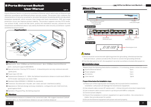
Please check the following items before installation, if it is missing, please contact the dealer .Accessory 1pcspcs 1) Please turn off the signal power and display device power before installation, installation with power will damage the transmission equipment;2) Use network cable connect IP camera and 1~8 down link ports of product respectively;3) Use a network cable connect switch's up link port with NVR or computer;4) Connect power adapter;5) Check if the installation is correct, equipment is in good condition, the connection is stable, then provide power for system;6) Ensure the Ethernet equipment with power and work properly.8 ports Ethernet Switch is a surveillance Ethernet switch which aims at Ethernet high definition surveillance and Ethernet project security system. The product fully combines the characteristics of security surveillance, provides fast packet forwarding ability and abundant backplane bandwidth, which ensures clear image andfluenttransmission. ESD and surge protection circuit can improve product stability. The product supports one key CCTV mode, can achieve VLAN, control the Net storm, protect the information security,prevent the viral transmission and Ethernet attack, fully satisfy the Ethernet video security surveillance systemand Ethernet project needs.security● Major ports: 1pcs 100Mbps up link Ethernet port, 8pcs 100Mbps downlink Ethernet ports , each port supports MDI/MDIX;● Special function: One key CCTV mode;1~8 downlink ports can only communicate with uplink ports;● Power input: DC12V;● Transmission Distance: 0~100m; the farthest transmission distance could reach 250m in CCTV model; Uplink port can reach 100m;● Standard: Meet IEEE802.3, IEEE802.3u standards;● Protection: Excellent anti-thunder, anti-static and anti-interference ability;● Appearance: Delicate design and easy installation, configure the anti-theft lock hole, guard against theft;●Operation: Plug and Play, No Setting required.The transmission distance is related to the connected cable. We suggest standard Cat5e/61) level will reduce; please use above No.20 wire to connect the grounding terminal.2) Turn the dial switch for left, the equipment can enter surveillance module after power on.Device must be connected with lightning protection grounding; otherwise protection indicated lightindicated lightnormally onKensington lockPlease follow below the installation stepsEthernet portEthernet portinput portSpecification change will not be noticedPlease follow the steps if the equipment has trouble. Make sure the equipment is installed according to the manufactures installation guide.Confirm RJ45 cable order meets EIA/TIA568A or 568B standard.Replace the equipment that can not work with a good one to check if the equipment is damaged.Please contact your vendor if trouble still exists.Instruments to be used: wire crimper, network tester. Wire sequence of RJ45 plug should conform with EIA/TIA568A or 568B.1) Please remove 2cm long the insulating layer, and bare 4 pairs UTP cable; 2) Separate the 4 pairs UTP cable and straighten them;3) Line up the 8 pieces of cables per EIA/TIA 568A or 568B;4) Cut off the cables to leave 1.5cm bare wire;5) Plug 8 cables into RJ45 plug, make sure each cable is in each pin;6) Use the wire crimper to crimp it;7) Repeat above 5 steps to make the another end;8) Using network tester to test the cable if it works.EIA/TIA 568AEIA/TIA 568BWhen choose RJ45 make sure if one end is EIA/TIA568A,the other end should also be EIA/TIA568A.When choose RJ45 make sure if one end is EIA/TIA568B,the other end should also be EIA/TIA568B.Notice。
Lab.gruppen C 10 8X 放大器商品介绍说明书

* Maximum continuous output power, all channels driven, VPL set at 100 V and Gain set at 32 dB▸▸Auditoriums▸▸Performing▸Arts▸Centers ▸▸Convention▸Centers ▸▸Stadiums▸and▸Arenas ▸▸Theme▸Parks ▸▸Hotels▸▸Houses▸of▸Worship▸▸Restaurants ▸▸Clubs▸▸Educational▸Establishments ▸▸Boardrooms ▸▸Museums ▸▸Offices▸▸Shopping▸Malls▸▸Transportation▸FacilitiesApplicationsAn▸Installation▸Amplifier▸without▸CompromiseLab.gruppen amplifiers have earned an enviable worldwide reputa-tion for sonic excellence and rock-solid durability in touring sound applications. These same qualities are now available for a broad range of installed sound applications in the C 10:8X amplifier. By offering an unmatched combination of channel density, operating efficiency and configuration flexibility, the C 10:8X presents convin-cing performance and cost-saving advantages. Applications include primary systems for theme parks, shopping malls, airports, hotels and restaurants as well as auxiliary systems for performance venues, houses of worship and numerous other installed sound applications.To achieve higher channel density without compromising per-formance, Lab.gruppen engineers developed a new output stage design. Based on a patented Class D circuit topology, these output stages produce sustained high power levels with very low distortion while maintaining efficiency levels of near 90%. A new universal switching power supply employs Power Factor Correction (PFC) to stabilize current draw, and it accepts any mains voltage from 65 – 265 V (+/- 10%) @ 50 Hz or 60 Hz through the appropriate IEC cord.The C 10:8X includes include unique features which enable each unit – or even each channel – to be configured for a specific application or load condition. Input gain is selectable in four-channel groups, and a 35 Hz high pass filter may be inserted. All channels are bridgeable in pairs, and Lab.gruppen’s exclusive Voltage Peak Limiter (VPL) feature allows each channel to be individually optimized for the reactive characteristics of the connected load.For comprehensive remote monitoring and control, the C 10:8X includes NomadLink ® network ports for connecting to an optional NLB 60E NomadLink ® Bridge & Controller Network and an Ethernet-linked PC. With NomadLink ®, key amplifier parameters are displayed via DeviceControl software, and remote control of channel mute and power on/off is under network control. Alternatively, the GPIO facilities allow access to key amplifier functions via third-party remote control systems.To ensure a long and trouble-free service life, the C 10:8X incorpo-rates extensive features to safeguard internal circuits and connected loads. Protection and warning circuits prevent damage or service in-terruptions due to excessive current, DC at output, over-temperature, non-musical VHF (very high frequencies), and open load conditions. In addition, soft-start and PSU current limiting protect the mains sup-ply from interruptions due to tripped circuit breakers or blown mains fuses.▸Eight▸channels▸in▸2U▸- Extremely high channel density reduces space requirements and installation time ▸High▸continuous▸output▸power▸of▸125▸W▸per▸channel▸at▸70▸V,▸4▸ohms,▸8▸ohms,▸and▸16▸ohms* ▸All▸channels▸individually▸selectable▸for▸lo-Z▸or▸hi-Z▸▸Loudspeakers (2 ohm – 16 ohm) and distributed systems can be connected to the same unit ▸Bridged▸operation▸–▸Channel pairs bridgeable for increased output or for driving 100 V systems ▸Patented▸output▸stage▸based▸on▸Class▸D▸topology ▸High▸efficiency▸for▸lower▸thermal▸stress▸General▸Purpose▸Input/Output▸(GPIO)▸–▸Compatible with third-party control systems ▸NomadLink®▸network▸ready▸Universal▸Power▸Factor▸Corrected▸PSU▸with▸IEC▸inlet▸ ▸Efficient▸cooling▸–▸Dual variable speed fans and parallel airflow over output devices provide uniform cooling ▸Comprehensive▸circuit▸protection▸and▸fault▸indication ▸Phoenix-style▸input▸connectors▸and▸barrier▸strip▸output▸connectorsC 10:8XItem no. TDS-C108X_V7GeneralNumber of channels8Peak total output all channels driven 1000 WPeak output voltage per channel 100 V / 70 Vrms Max. output current per channel 5.6 Arms Max.▸Output▸Power 16▸ohms 8▸ohms 4▸ohms 2▸ohms Hi-ZPer ch. (all ch.’s driven)125 W 125 W 125 W 60 W 125 W (70 Vrms / 100 V peak)Bridged per ch.250 W250 W125 Wn.r.250 W (140 Vrms / 200 V peak)Performance▸with▸Gain:▸32▸dB▸and▸VPL:▸100▸V THD 20 Hz - 20 kHz for 1 W<0.1%THD at 1 kHz and 1dB below clipping <0.05%Signal To Noise Ratio>112 dBA Channel separation (Crosstalk) at 1 kHz>70 dBFrequency response (1 W into 8 ohms) +0/-3 dB 6.8 Hz - 34 kHz Input impedance20 kOhm Input Common Mode Rejection, CMR 50 dB Output impedance @ 100 Hz48 mOhmVoltage▸Peak▸Limiter▸(VPL),▸max.▸peak▸output VPL, selectable per ch. 3)100, 63, 45, 32 V VPL, selectable when bridged 3) 1)200, 126, 90, 64 V Voltage Peak Limiter mode (per ch.)Hard / SoftGain▸and▸LevelAmplifier gain selectable (all channels) 1) – rear-panel switches 29, 32, 35, 38 dBDefault gain32 dBLevel adjustment (per ch.)Front-panel potentiometer, 21 position detented from -inf to 0 dB, hidden behind security panel/dust filter grilleConnectors▸and▸switches Input connectors (per ch.)3-pin Phoenix, electronically balanced Output connectors (per ch.)Barrier strip 2-pole screw terminals Output bridge mode A+B, C+D, E+F , G+H, inputs A, C, E, G are signal source High pass filterFixed at 35 Hz, switchable per channelNomadLink ® network On board, 2 x RJ45 connectors, IN and OUT Intelligent fans (on/off)Y es, depending on presence of output signal Power on/off and Remote enable on/off Individual switches on front-panelCoolingTwo fans, front-to-rear airflow, temperature controlled speed General Purpose Outputs (GPO)Contact Closure types, 2-pole Phoenix General Purpose Inputs (GPI)Contact Closure types, 2-pole PhoenixFront-panel▸indicators Common NomadLink ® Network; Power Average Limiter (PAL) 2); Power onPer channelSignal present / High-impedance; Voltage Peak Limiter (VPL); Current Peak Limiter (CPL); Very High Frequency (VHF); High temperature; Fault; MutePowerOperating voltage, 230 V / 115 V nominal 65-265 V Minimum power-up voltage, 230 V / 115 V 80 V Power Average Limiter (PAL) 2)YesSoft start / Inrush current draw Yes / max. 5 A Mains connector IEC InletDimensions▸(W/H/D)W: 483 mm (19”), H: 88 mm (2 U), D: 343 mm (13.5”)Weight 8.5 kg (18.75 lbs.)FinishBlack painted steel chassis with gray painted steel front ApprovalsCE, ANSI/UL 60065 (ETL), CSA C22.2 NO. 60065, FCCNote▸1): Automatic -6 dB gain compensation when bridging channels. Ch.’s A+B and/or C+D, E+F, G+H, can be bridged individually.▸Note▸2): PAL can reduce the maximum output power to keep the power supply operating safely, and/or to prevent excessive current draw tripping the mains breaker. Refer to Operation Manual.▸Note▸3): For sine waves, peak voltage output values translate to Vrms with the formula V/1.41 = Vrms. E.g. 100 V peak equals app. 70 Vrms. Hence, outputs can be set for high-impedance loads without requiring a transformer.▸All▸specifications▸are▸subject▸to▸change▸without▸notice.L a b .g r u p p e n a b ▸ S w e d e ni n t e r n a t i o n a L c o n t a c t ▸ i n f o @L a b g r u p p e n .c o m | u S & c a n a d a c o n t a c t ▸ i n f o @t c g -a m e r i c a S .c o mw w w .l a b g r u p p e n .c o mSpecifications C 10:8X。
TEC8-中断原理实验

TEC-8 北京邮电大学计算机学院试验中心系统构造试验室
13
地址
指令
机器码
00H
EI
01H
INC R0
02H
INC R0
03H
INC R0
04H
INC R0
05HINC Leabharlann 006HINC R0
07H
INC R0
08H
INC R0
1
三、试验设备 TEC-8试验系统 1台 TDS1001数字存储示波器 1台 UT60A数字万用表 1块 逻辑测试笔(在TEC-8试验台上) 1支 四、试验电路
TEC-8 北京邮电大学计算机学院试验中心系统构造试验室
2
TEC-8模型计算机中有一种简朴旳单级中断系统, 只支持单级中断、单个中断祈求,有中断屏蔽功 能,旨在阐明最基本旳工作原理。
TEC-8模型计算机中有2条指令用于允许和屏蔽中 断。EI指令称作开中断指令,此条指令执行后, TEC-8响应中断。DI指令称作关中断指令。此条 指令执行后,虽然发生中断祈求,TEC-8也不响应 中断祈求。
按下PULSE按钮产生高电平有效旳中断祈求脉冲 信号。
TEC-8 北京邮电大学计算机学院试验中心系统构造试验室
TEC-8 北京邮电大学计算机学院试验中心系统构造试验室
17
《 计算机构成原理 》第五版 白中英 主编 科学出版社
《TEC-8 计算机硬件综合试验系统试验 指导书》清华大学科教仪器厂
TEC-8 北京邮电大学计算机学院试验中心系统构造试验室
18
打开电源。
TEC-8 北京邮电大学计算机学院试验中心系统构造试验室
H3C帧中继配置
H3C帧中继配置实验:h3cmsr路由器模拟帧中继交换机注:本实验使用H3C模拟器,版本为wrvp5 2a我已经将其整合成为一个帧中继机架,对着拓扑图来做实验就可以了。
1.双击go。
在每个设备文件夹下启动虚拟设备2.登陆设备:telnet127.0.0.1端口号r1--------2001r2--------2002r3--------2021fr-sw-----20213.配置在此我先从fr-sw开始配置,先把帧中继环境搭建起来,随后再配置剩余的设备,话不多说,看操作。
实验参考命令:frswitching//msr路由器模拟帧中继交换机必须启用此命令frlmitypeq933a//默认就是这种类型,可以不必敲入此命令frinterfacedce//帧中继交换机上的接口都配置成dcefrinterfacedte//dte端默认是dte,可以不用敲入此命令frdlcidlci-numberFriarpipdlci编号//反向ARP。
在这个实验中,只配置了静态映射,所以不使用这个命令。
显示FRSWITCH表格所有DISPRMAP信息DISFRStatisticsDISFRPVC信息验证:disfrinterfaces0/2/1disfrmap-infoints0/2/1disfrlmi-infointdisfrstatisticsintdisfrpvc-infointdisfrdlci switchint[r1]interfaceserial0/2/1link-protocolfrfrmapip192。
168.123.2102frmapip192。
168.123.3103ipaddress192.168.123.1255.255.255.0[r2]interfaceserial0/2/1链接协议fRfrmapip192.168.123.1201IP地址192。
168.123.2255.255.255.0[r3]interfaceserial0/2/1link-protocolfrfrmapip192。
华三交换无线控标参数-16.6.6

交换机部分LS-7506E-X版本一:1、★要求采用CLOS正交多级交换架构,能够配置独立的交换网板与独立的主控板。
主控板、交换网板、业务板物理分离;2、★交换容量≥90Tbps,包转发率≥28000Mpps,业务插槽数量≥6,主控板槽位≥2,支持引擎、单板、电源热插拨,支持主控板卡、电源、接口模块等关键部件冗余配置。
提供官方产品彩页证明;3、★业务板卡与交换网板采用完全正交设计(90度),跨线卡业务流量通过正交连接器直接上交换网板,背板走线降低为零,极大规避信号衰减;提供官网截图及公开链接证明;4、支持以太网千兆电口,千兆光口,10GE端口、40G端口、100G端口;万兆光口单板密度≥48个,单槽位40G端口密度≥12个,100G接口单板密度≥2个;提供官网链接及选配信息截图证明;5、支持通过核心交换机任意万兆端口(非特定板卡或端口)即可实现将三台以上物理设备虚拟化为一台逻辑上的设备,虚拟化后可实现统一的转发表项、统一的管理界面以及跨物理设备的链路聚合,并且无需独立的硬件模块支持。
6、为适应未来云计算发展趋势,要求设备支持丰富的云计算数据中心特性,如FcoE、TRILL等功能。
7、支持OSPF/IS-IS/BGP GR,支持虚拟路由冗余协议(VRRP)、支持双引擎负载分担;提供软件热补丁技术,实现设备软件完全平滑升级。
8、支持纵向虚拟化,将配套的接入盒式设备虚拟成自身的远程接口板,形成单一的逻辑虚拟设备,在管理层面实现单一节点管理。
9、★支持扩展专用防火墙插卡、IPS插卡、NetStream、负载均衡功能插卡、应用控制插卡,以上扩展模块均为独立硬件,非通过扩展license方式实现,提供官网选配信息截图证明并提供独立的产品彩页。
10、厂商须通过TL9000电信业质量管理体系认证、CMMI4软件能力成熟度认证,提供证书复印件;11、厂商须通过ISO20000信息技术服务管理体系认证、ISO27001信息安全管理体系认证,提供证书复印件;12、★投标产品供应商必需通过知识产权管理体系认证,能够全面保护、并系统管理知识产权,支撑企业的技术创新能力,提供知识产权管理体系认证证书;13、配置要求:单台设备需配置双主控引擎、交换网板≥1块、交流电源≥3块;配置同时可用千兆电口≥24个、万兆SFP+光口≥4个、千兆光口≥20个;版本二:1、交换容量≥96Tbps,包转发率≥28800Mpps,提供官方产品彩页证明;2、★要求采用CLOS正交多级交换架构,能够配置独立的交换网板与独立的主控板。
rp-8中继器用法 -回复
rp-8中继器用法-回复RP8中继器用法中继器是一种网络设备,用于加强和扩展网络信号的传输范围。
RP8中继器作为常见的一种中继器,具有广泛的应用场景和用途。
本文将以RP8中继器用法为主题,逐步详细介绍RP8中继器的设置和应用。
第一步:了解RP8中继器的基本功能和原理RP8中继器是一种物理层设备,用于扩展以太网的连续传输距离。
它提供了额外的端口,允许用户将多个设备连接到网络中。
RP8中继器通过接收、整理和放大来自一个端口的信号,然后将信号转发到其他端口。
这种信号放大和转发的功能使得RP8中继器能够扩展网络的传输范围,提高网络的可靠性和稳定性。
第二步:确定RP8中继器的布置位置在设置RP8中继器之前,需要确定它的布置位置。
如果您希望将RP8中继器用于扩展无线网络信号,那么最好将其放置在离无线路由器或接入点远离的地方,以确保信号穿透能力的最大化。
如果您希望将RP8中继器用于有线网络扩展,那么可以将其放置在距离主路由器较远的位置,以便连接更多的有线设备。
第三步:连接RP8中继器到主网络设备将RP8中继器的一个端口连接到主网络设备(如无线路由器或交换机)的一个空闲端口。
通常,您可以使用一根网线将它们连接起来。
确保连接牢固,然后将RP8中继器插入电源插座以供电。
第四步:配置RP8中继器RP8中继器通常不需要额外的配置,几乎是即插即用的设备。
然而,为了最大程度地利用RP8中继器的功能和性能,您可能需要进行一些基本的设置。
具体的配置步骤可能因不同品牌和型号的中继器而有所不同,请参考RP8中继器的使用手册或厂商的官方技术支持。
第五步:测试RP8中继器的功能完成配置后,您可以开始测试RP8中继器是否正常工作。
首先,通过手机、平板电脑或电脑的Wi-Fi功能,搜索并连接到RP8中继器创建的无线网络。
如果您使用的是有线网络,可以将设备连接到RP8中继器提供的有线端口上。
在完成连接之后,测试网络连接的速度和稳定性。
您可以使用网络速度测试工具(如Speedtest)来测量网络的下载和上传速度。
八位十进制数字频率计

EDA课程设计陈说书之南宫帮珍创作题目:8位十进制数字频率计的设计姓名:学号:所属学院:专业年级:指导教师:完成时间:8位十进制数字频率计的设计一、设计介绍数字频率计是采纳数字电路制做成的能实现对周期性变动信号频率丈量的仪器.频率计主要用于丈量正弦波、矩形波、三角波和尖脉冲等周期信号的频率值.其扩展功能可以丈量信号的周期和脉冲宽度.通常说的, 数字频率计是指电子计数式频率计.频率计主要由四个部份构成:输入电路、时基(T)电路、计数显示电路以及控制电路.在电子技术领域, 频率是一个最基本的参数.数字频率计作为一种最基本的丈量仪器以其丈量精度高、速度快、把持简便、数字显示等特点被广泛应用.许多物理量, 例如温度、压力、流量、液位、PH值、振动、位移、速度等通过传感器转换成信号频率, 可用数字频率计来丈量.尤其是将数字频率计与微处置器相结合, 可实现丈量仪器的多功能化、程控化和智能化.随着现代科技的发展, 基于数字式频率计组成的各种丈量仪器、控制设备、实时监测系统已应用到国际民生的各个方面.二、设计目的(1)熟悉Quatus 11软件的基本使用方法.(2)熟悉EDA实验开发系统的使用方法.(3)学习时序电路的设计、仿真和硬件设计, 进一步熟悉VHDL设计技术.三、数字频率计的基来源根基理数字频率计的基来源根基理是用一个频率稳定度高的频率源作为基准时钟, 通常情况下计算每秒内待测信号的脉冲个数,此时我们称闸门时间为1秒.闸门时间也可以年夜于或小于一秒.闸门时间越长, 获得的频率值就越准确, 但闸门时间越长则每测一次频率的间隔就越长.闸门时间越短, 测的频率值刷新就越快,但测得的频率精度就受影响.数字频率计的主要功能是丈量周期信号的频率.频率是单元时间(1S)内信号发生周期变动的次数.如果我们能在给定的1S时间内对信号波形计数, 并将计数结果显示出来, 就能读取被测信号的频率.数字频率计首先必需获得相对稳定与准确的时间, 同时将被测信号转换成幅度与波形均能被数字电路识另外脉冲信号, 然后通过计数器计算这一段时间间隔内的脉冲个数, 将其换算后显示出来.这就是数字频率计的基来源根基理.频率计丈量频率需要设计整形电路使被测周期性信号整形成脉冲, 然后设计计数器对整形后的脉冲在单元时间内重复变动的次数进行计数, 计数器计出的数字经锁存器锁存后送往译码驱动显示电路用数码管将数字显示出来, 需要设计控制电路发生允许发生的门匣信号, 计数器的清零信号和锁存器的锁存信号使电路正常工作, 再设计一个量程自动转换使丈量范围更广.四系统总体框架图 3.1 系统总体框架图总体框图设计思路:由50MHz系统时钟分频获得0.5Hz的基准时钟.在基准时钟的1S 高电平期间计被测频率的脉冲个数, 1S 高电平结束时计数结束, 所记录的脉冲个数是被测信号的频率, 为了在数码管上显示计数结果需要锁存器将所计的数锁存, 因此, 在基准时钟下降沿来的时候锁存器实现锁存功能.为了下次计数必需将本次计数的结果清零, 所以在基准时钟低电平期间对计数器清零.被测频率从计数器的是中端输入实现频率的测试.将锁存器锁存的数据输入扫描器, 通过译码器将锁存的二进制数译成十进制然后显示到数码管上, 最终被读出来.五、设计内容实验条件:(1)开发条件:Quatus 11软件.(2)实验设备:GW48-ES EDA实验开发系统, 电脑.(3)拟用芯片: EPF10K20TC144-4芯片.源法式:--test controler(测频控制器)LIBRARY IEEE;USE IEEE.STD_LOGIC_1164.ALL;USE IEEE.STD_LOGIC_UNSIGNED.ALL;ENTITY TESTCTL ISPORT (CLKK : IN STD_LOGIC ;--test 1HZ control clkCNT_EN,RST_CNT,LOAD : OUT STD_LOGIC); --clear the enable , count,END TESTCTL;ARCHITECTURE BEHAV OF TESTCTL ISSIGNAL DIV2CLK : STD_LOGIC ;BEGINPROCESS (CLKK)BEGINIF CLKK'EVENT AND CLKK = '1' THENDIV2CLK <= NOT DIV2CLK;END IF;END PROCESS;PROCESS(CLKK,DIV2CLK)BEGINIF CLKK = '0' AND DIV2CLK = '0' THEN RST_CNT <= '1';ELSE RST_CNT <= '0';END IF;END PROCESS;LOAD <= NOT DIV2CLK;CNT_EN <= DIV2CLK;END BEHAV;-- COUNT10 (CNT10.VHD)(十进制计数器)LIBRARY IEEE;USE IEEE.STD_LOGIC_1164.ALL;USE IEEE.STD_LOGIC_UNSIGNED.ALL;ENTITY CNT10 ISPORT(CLK : IN STD_LOGIC;CLR : IN STD_LOGIC;ENB : IN STD_LOGIC;OUTY: OUT STD_LOGIC_VECTOR(3 DOWNTO 0);COUT: OUT STD_LOGIC);END CNT10;ARCHITECTURE BEHAV OF CNT10 ISBEGINPROCESS(CLK,CLR,ENB)VARIABLE CQI : STD_LOGIC_VECTOR (3 DOWNTO 0); BEGINIF CLR = '1' THEN CQI :="0000";ELSIF CLK'EVENT AND CLK = '1' THENIF ENB = '1' THENIF CQI < "1001" THEN CQI := CQI+1;ELSE CQI :="0000";END IF;END IF;END IF;OUTY <= CQI;COUT <= CQI(0) AND (NOT CQI(1)) AND (NOT CQI(2)) AND CQI(3);END PROCESS;END BEHAV;--REGISTER (REG4B.VHD)(4位锁存器)LIBRARY IEEE;USE IEEE.STD_LOGIC_1164.ALL;ENTITY REG4B ISPORT (LOAD : IN STD_LOGIC;DIN : IN STD_lOGIC_VECTOR(3 DOWNTO 0);DOUT : OUT STD_LOGIC_VECTOR (3 DOWNTO 0));END REG4B;ARCHITECTURE BEHAV OF REG4B ISBEGINPROCESS (LOAD ,DIN)BEGINIF LOAD'EVENT AND LOAD = '1' THEN DOUT <= DIN ; --SUO CUN END IF;END PROCESS;END BEHAV;———8位十进制频率计LIBRARY IEEE;USE IEEE.STD_LOGIC_1164.ALL;USE IEEE.STD_LOGIC_UNSIGNED.ALL;entity choose isport( clk:in std_logic;a,b,c,d,e,f,g,h:in STD_LOGIC_VECTOR(3 DOWNTO 0);x,y:out STD_LOGIC_VECTOR(7 DOWNTO 0));end;ARCHITECTURE ONE OF choose ISsignal ain:STD_LOGIC_VECTOR(2 DOWNTO 0);signal bin:STD_LOGIC_VECTOR(3 DOWNTO 0);beginprocess(clk)beginif(clk'event and clk='1') thenif(ain="111") then ain<="000";else ain<=ain+'1';end if;end if;end process;process(ain)begincase ain iswhen"000"=>bin<=a;y<="11111110"; when"001"=>bin<=b;y<="11111101"; when"010"=>bin<=c;y<="11111011"; when"011"=>bin<=d;y<="11110111"; when"100"=>bin<=e;y<="11101111"; when"101"=>bin<=f;y<="11011111"; when"110"=>bin<=g;y<="10111111"; when"111"=>bin<=h;y<="01111111"; when others=>null;end case;end process;process(bin)begincase bin iswhen"0000"=>x<="11111100"; when"0001"=>x<="01100000"; when"0010"=>x<="11011010"; when"0011"=>x<="11110010"; when"0100"=>x<="01100110";when"0101"=>x<="10110110"; when"0110"=>x<="10111110"; when"0111"=>x<="11100000"; when"1000"=>x<="11111110"; when"1001"=>x<="11110110";when others=>null;end case;end process;end;--QUENT1LIBRARY IEEE;USE IEEE.STD_LOGIC_1164.ALL;USE IEEE.STD_LOGIC_UNSIGNED.ALL;ENTITY QUENT1 ISPORT(CLKIN : IN STD_LOGIC;FIN : IN STD_LOGIC;scan : OUT STD_LOGIC_VECTOR(7 DOWNTO 0); seg : OUT STD_LOGIC_VECTOR(7 DOWNTO 0); COUTT: OUT STD_LOGIC );END ENTITY QUENT1;ARCHITECTURE ONE OF QUENT1 IS COMPONENT chooseport( clk:in std_logic;a,b,c,d,e,f,g,h:in STD_LOGIC_VECTOR(3 DOWNTO 0);x,y:out STD_LOGIC_VECTOR(7 DOWNTO 0));end COMPONENT;COMPONENT TESTCTLPORT (CLKK : IN STD_LOGIC;CNT_EN , RST_CNT,LOAD : OUT STD_LOGIC);END COMPONENT;COMPONENT CNT10PORT (CLK : IN STD_LOGIC;CLR : IN STD_LOGIC;ENB : IN STD_LOGIC;OUTY: OUT STD_LOGIC_VECTOR(3 DOWNTO 0);COUT: OUT STD_LOGIC);END COMPONENT;COMPONENT REG4BPORT (LOAD : IN STD_LOGIC;DIN : IN STD_LOGIC_VECTOR(3 DOWNTO 0);DOUT : OUT STD_LOGIC_VECTOR(3 DOWNTO 0));END COMPONENT;SIGNALA_ENA,B_RST,C_LOAD,COUT1,COUT2,COUT3,COUT4,COUT5,COUT6,CO UT7 : STD_LOGIC;SIGNALOUTY1,OUTY2,OUTY3,OUTY4,OUTY5,OUTY6,OUTY7,OUTY8,out1,out2 ,out3,out4,out5,out6,out7,out8 : STD_LOGIC_VECTOR(3 DOWNTO 0);BEGINU1 : TESTCTL PORT MAP (CLKK=> CLKIN,CNT_EN=>A_ENA,RST_CNT=>B_RST,LOAD=>C_LOAD);U2 : CNT10 PORT MAP(CLK=> FIN,CLR=>B_RST,ENB=>A_ENA,OUTY=>OUTY1,COUT=>COUT1);U3 : CNT10 PORT MAP(CLK=> COUT1,CLR=>B_RST,ENB=>A_ENA,OUTY=>OUTY2,COUT=>COUT2);U4 : CNT10 PORT MAP(CLK=> COUT2,CLR=>B_RST,ENB=>A_ENA,OUTY=>OUTY3,COUT=>COUT3);U5 : CNT10 PORT MAP(CLK=> COUT3,CLR=>B_RST,ENB=>A_ENA,OUTY=>OUTY4,COUT=>COUT4);U6 : CNT10 PORT MAP(CLK=> COUT4,CLR=>B_RST,ENB=>A_ENA,OUTY=>OUTY5,COUT=>COUT5);U7 : CNT10 PORT MAP(CLK=> COUT5,CLR=>B_RST,ENB=>A_ENA,OUTY=>OUTY6,COUT=>COUT6);U8 : CNT10 PORT MAP(CLK=> COUT6,CLR=>B_RST,ENB=>A_ENA,OUTY=>OUTY7,COUT=>COUT7);U9 : CNT10 PORT MAP(CLK=> COUT7,CLR=>B_RST,ENB=>A_ENA,OUTY=>OUTY8,COUT=>COUTT);U10 : REG4B PORT MAP(LOAD=> C_LOAD,DIN=> OUTY1,DOUT=>OUT1);U11 : REG4B PORT MAP(LOAD=> C_LOAD,DIN=> OUTY2,DOUT=>OUT2);U12 : REG4B PORT MAP(LOAD=> C_LOAD,DIN=>OUTY3,DOUT=>OUT3);U13 : REG4B PORT MAP(LOAD=> C_LOAD,DIN=> OUTY4,DOUT=>OUT4);U14 : REG4B PORT MAP(LOAD=> C_LOAD,DIN=> OUTY5,DOUT=>OUT5);U15 : REG4B PORT MAP(LOAD=> C_LOAD,DIN=> OUTY6,DOUT=>OUT6);U16 : REG4B PORT MAP(LOAD=> C_LOAD,DIN=> OUTY7,DOUT=>OUT7);U17 : REG4B PORT MAP(LOAD=> C_LOAD,DIN=> OUTY8,DOUT=>OUT8);u18 : choose port map(clk=>fin,a=>out1,b=>out2,c=>out3,d=>out4,e=>out5,f=>o ut6,g=>out7,h=>out8,x=>scan,y=>seg);END ARCHITECTURE ONE;六原理图七、总结(1)设计小结本次设计中, 我们胜利完本钱系统设计所要求的八位十进制频率计的测频功能.在设计开始前我们就系统整体框架和各个模块功能进行了详细的分析和设计准备工作, 设计过程中, 我们相互协调, 积极介入讨论, 最终克服了所有遇到的技术难点.(2)设计收获通过本次设计, 我们在对EDA这门技术上有了更深刻的认识, 也在实践过程中感受到了EDA设计给我们设计带来的方便.在这个过程中, 我们不单比力熟练地掌握了QuartusII软件的使用, 与此同时, 我们还对电子设计的思路有了更清晰的认识.通过对EDA设计我们更深入的了解了可编程逻辑器件的各个功能, 也从中学到了很多电子电路设计方面的知识, 为我们以后从事设计工作打下了一定的基础, 虽然设计的系统不算完美, 可是我确信自己努力认真了, 从中学到了知识、开阔了眼界, 这也是课程设计真正目的所在.(4)设计改进由于自身能力有限, 学到的知识未几, 本次八位十进制频率计的设计仅仅是完成了一些基本的功能, 如计数, 锁存, 译码和显示, 在实际的频率丈量中, 信号在进入计数器之前应该先经过放年夜整形电路, 将信号转化为标准的矩形波, 如果信号的频率太年夜, 还得要考虑是否要先对被测频率进行分频, 从而使得丈量结果更加精确稳定, 更具说服力, 频率计作为一种丈量仪器应该有自动换挡的功能, 从而才华方便使用.另一方面, 显示可以采纳液晶显示, 从而使显示的效果更加的美观.(5)致谢我们小组能够完成这次课程设计, 首先要感谢老师耐心细致的为我们分析题目, 提供解决方案, 如果没有老师的悉心指导, 我们的课程设计也不会进展的如此顺利, 并最终实现各个功能.另外还要感谢我的组员们, 和他们一起思考问题, 摸索quartus软件的使用方法, 仿真方法等.通过和他们一起思考, 讨论分析问题, 我。
- 1、下载文档前请自行甄别文档内容的完整性,平台不提供额外的编辑、内容补充、找答案等附加服务。
- 2、"仅部分预览"的文档,不可在线预览部分如存在完整性等问题,可反馈申请退款(可完整预览的文档不适用该条件!)。
- 3、如文档侵犯您的权益,请联系客服反馈,我们会尽快为您处理(人工客服工作时间:9:00-18:30)。
实验8 帧中继实验任务一:帧中继物理接口静态映射互通配置实验任务一中的PC以及路由器的IP地址规划如表8-1所示。
表8-1实验任务一IP地址规划设备接口IP地址/掩码本地DLCIRTA S1/0 10.1.1.1/24 30、40RTB S1/0 10.1.1.2/24 70RTC S1/0 10.1.1.3/24 80步骤一:运行超级终端并初始化路由器配置将PC(或终端)的串口通过标准Console电缆与路由器的Console口连接。
电缆的RJ-45头一端连接路由器的Console口;9针RS-232接口一端连接计算机的串行口。
检查设备的软件版本及配置信息,确保各设备软件版本符合要求,所有配置为初始状态。
如果配置不符合要求,请学员在用户视图下擦除设备中的配置文件,然后重启设备以使系统采用缺省的配置参数进行初始化步骤二:依据规划,配置相关的IP地址依据表8-1规划的IP地址,为路由器的接口配置IP地址。
步骤三:配置广域网接口封装在RTA上做如下配置:[RTA-Serial1/0] link-protocol fr ietf,该命令的含义是封装接口的链路层协议为帧中继,命令中IETF的含义是选择IETF标准(ietf)格式进行帧中继封装在RTB、RTC上完成同样的配置步骤四:配置RTA上帧中继相关参数在RTA的Serial 1/0接口上配置如下:[RTA-Serial1/0] fr interface-type dte该命令的含义是配置帧中继接口类型是DTE[RTA-Serial1/0] fr lmi type Q933a该命令的含义是配置帧中继接口的LMI协议类型为Q933a[RTA-Serial1/0] fr map ip 10.1.1.2 30[RTA-Serial1/0] fr map ip 10.1.1.3 40请在空格处补充完整的配置并说明该配置命令的含义配置帧中继的地址映射,其中IP地址是对端的IP地址,DLCI是本地虚电路号[RTA-Serial1/0] ip address 10.1.1.1 24步骤五:配置RTB、RTC上帧中继相关参数请在如下空格处补充完全RTB上帧中继相关的配置:[RTB-Serial1/0] fr interface-type dte[RTB-Serial1/0] fr lmi type Q933a[RTB-Serial1/0] fr map ip 10.1.1.1 70[RTB-Serial1/0] ip address 10.1.1.2 24请在如下空格处填写完整的RTC上帧中继相关的配置:[RTC-Serial1/0] fr interface-type dte[RTC-Serial1/0] fr lmi type Q933a[RTC-Serial1/0] fr map ip 10.1.1.1 80[RTC-Serial1/0] ip address 10.1.1.3 24步骤六:配置路由器模拟帧中继交换机配置路由器FR-Switch实现帧中继交换机功能:[fr switch]fr switching //启用帧中继交换机功能[fr switch]interface s6/0 //连接RTA[fr switch-Serial6/0]link-protocol fr[fr switch-Serial6/0]fr interface-type dce[fr switch-Serial6/0]fr dlci 30[fr switch-fr-dlci-Serial6/0-30]quit[fr switch-Serial6/0]fr dlci 40[fr switch-fr-dlci-Serial6/0-40]quit[fr switch]interface s5/0 //连接RTB[fr switch-Serial5/0]link-protocol fr[fr switch-Serial5/0]fr interface-type dce[fr switch-Serial5/0]fr dlci 70[fr switch-fr-dlci-Serial5/0-70]quit[fr switch]interface s5/1 //连接RTC[fr switch-Serial5/1]link-protocol fr[fr switch-Serial5/1]fr interface-type dce[fr switch-Serial5/1]fr dlci 80[fr switch-fr-dlci-Serial5/0-80]quit[fr switch]fr switch a-b interface Serial6/0 dlci 30 interface Serial5/0 dlci 70 [fr switch-fr-switching-a-b]quit[fr switch]fr switch a-c interface Serial6/0 dlci 40 interface Serial5/1 dlci 80 [fr switch-fr-switching-a-c]quit检测帧中继交换机配置是否成功:<fr switch>display fr switch-table allTotal PVC switch records:2PVC-Name Status Interface(Dlci) <-----> Interface(Dlci)a-b Active Serial6/0(30) Serial5/0(70)a-c Active Serial6/0(40) Serial5/1(80) 发现两个通道都已经active,通道配置成功。
步骤七:查看验证接口配置的正确性在RTA上执行命令display fr map-info,根据该其输出信息可以看到:DLCI = 30, IP 10.1.1.2, Serial1/0 status = activeDLCI = 40, IP 10.1.1.3, Serial1/0 status = active在RTB、RTC上执行同样的命令查看相关信息在RTA上执行命令display fr lmi-info,根据其输出信息可以看到:out status enquiry = 243, in status = 24330秒之后,在RTA上重复执行命令display fr lmi-info,根据其输出信息可以看到out status enquiry数值增加(增加/减少),in status数值增加(增加/减少)在RTB、RTC上完成同样如上的操作注意:步骤八中out status enquiry显示的数值只作为参考,具体数值以实验室的执行命令display fr lmi-info后的显示值为准。
步骤八:验证互通性在RTA上ping RTB、RTC的S1/0接口IP地址,其结果是可以互通实验任务二:帧中继子接口静态映射互通配置实验任务二中的PC以及路由器的IP地址规划如表8-2所示。
表8-2实验任务二IP地址规划设备接口IP地址/掩码本地DLCIS1/0.1 10.1.1.1/30 30RTAS1/0.2 10.1.2.1/30 40RTB S1/0 10.1.1.2/30 70RTC S1/0 10.1.2.2/30 80步骤一:运行超级终端并初始化路由器配置将PC(或终端)的串口通过标准Console电缆与交换机的Console口连接。
电缆的RJ-45头一端连接路由器的Console口;9针RS-232接口一端连接计算机的串行口。
检查设备的软件版本及配置信息,确保各设备软件版本符合要求,所有配置为初始状态。
如果配置不符合要求,请学员在用户视图下擦除设备中的配置文件,然后重启设备以使系统采用缺省的配置参数进行初始化步骤二:依据规划,配置相关的IP地址依据表8-2规划的IP地址,为路由器的接口配置IP地址。
步骤三:配置路由器上帧中继相关参数实现帧中继协议的封装标准为IEF格式,帧中继接口的终端类型为DTE,接口的LMI类型为Q933a,请在RTA接口S1/0上完成满足如上要求的配置:[RTA] interface serial 1/0[RTA-Serial1/0] link-protocol fr ietf.[RTA-Serial1/0] fr interface-type dte[RTA-Serial1/0] fr lmi type Q933a在RTB、RTC的接口S1/0上完成同样的配置步骤四:为RTA建立子接口,并配置子接口上的帧中继相关参数在RTA上建立子接口,请在如下空格处补充完整的命令[RTA]interface Serial 1/0.1 p2p该命令中P2P的含义是定义帧中继点到点类型子接口[RTA-Serial0/0.1]ip address 10.1.1.1 30[RTA-Serial0/0.1]fr dlci 30[RTA]interface Serial 1/0.2 p2p[RTA-Serial0/0.1]ip address 10.1.2.1 30[RTA-Serial0/0.1]fr dlci 40步骤五:配置RTB、RTC接口上的帧中继相关信息在RTB上配置帧中继子接口,请补充空格中完整的命令:interface Serial1/0.1 p2pfr dlci 70ip address 10.1.1.2 255.255.255.252请在如下的空格中完成RTC上帧中继子接口的配置:interface Serial 1/0.1 p2pfr dlci 80ip address 10.1.2.2 255.255.255.252步骤六:配置路由器模拟帧中继交换机本步骤中FR-Switch的配置与实验任务一相同,保留其配置不变即可。
步骤七:查看RTA子接口上的相关信息在RTA上执行命令display fr map-info,根据该其输出信息可以看到:DLCI 30, Point-to-Point DLCI, Serial1/0.1, status = activeDLCI 40, Point-to-Point DLCI, Serial1/0.2, status = active在RTB、RTC上执行同样的命令查看相关信息在RTA上执行命令display fr lmi-info,根据其输出信息可以看到:out status enquiry = 451, in status = 45130秒之后,在RTA上重复执行命令display fr lmi-info,根据其输出信息可以看到out status enquiry数值增加(增加/减少),in status数值增加(增加/减少)在RTB、RTC上完成同样如上的操作步骤八:验证互通性在RTA上ping RTB、RTC的S1/0.1接口IP地址,其结果是可以互通。
