T2550卡件介绍
255型双枪锁定版器件说明书
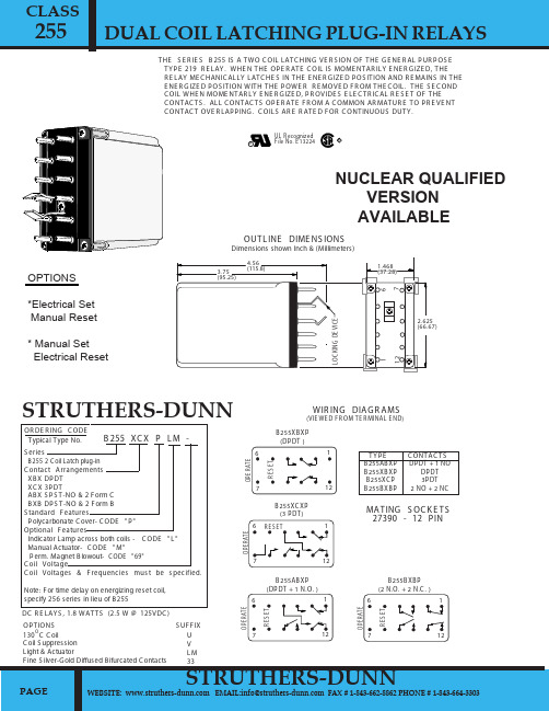
255RUL R ecognized File No. E 13224RTHE S E R IE S B 255 IS A TWO C OIL LATC HING VE R S ION OF THE G E NE R AL P UR P OS E TY P E 219 R E LAY. WHE N THE OP E R ATE C OIL IS MOME NTAR ILY E NE R G IZE D, THE R E LAY ME C HANIC ALLY LATC HE S IN THE E NE R G IZE D P OS ITION AND R E MAINS IN THE E NE R G IZE D P OS ITION WITH THE P OWE R R E MOVE D F R OM THE C OIL. THE S E C OND C OIL WHE N MOME NTAR LY E NE R G IZE D, P R OVIDE S E LE C TR IC AL R E S E T OF THE C ONTAC TS. ALL C ONTAC TS OP E R ATE F R OM A C OMMON AR MATUR E TO P R E VE NT C ONTAC T OVE R LAP P ING. C OILS AR E R ATE D F OR C ONTINUOUS DUTY.U V L M 33S UF F IXOP TIONS130 C C oilC oil S uppression Light & ActuatorF ine S ilver-G old Diffused B ifurcated C ontactsB 255 XC X P L M -S eriesB255 2 C oil Latch plug-in C ontact Arrangements XB X DP DT XC X 3P DTAB X S P S T-NO & 2 F orm C B XB DP S T-NO & 2 F orm B S tandard F eaturesP olycarbonate C over- C ODE "P "Optional F eaturesIndicator Lamp across both coils - C ODE "L " Manual Actuator- C ODE "M" P erm. Magnet B lowout - C ODE "69"C oil VoltageC oil Voltages & F requencies mus t be s pecified.Note: F or time delay on energizing reset coil,specify 256 series in lieu of B 255OR DE R ING C ODE Typical Type No.DC R E LAY S , 1.8 WATTS (2.5 W @ 125VDC )PAGEWEBSITE: EMAIL:info@ FAX # 1-843-662-8862 PHONE # 1-843-664-3303C ONTAC TS61712B 255XB XP (DP DT )61712B 255XC XP (3 P DT)61712B 255AB XP (DP DT + 1 N.O. )R E S E TO P E R A T EO P E R A T ER E S E TR E S E TO P E R A T E61712B 255B XB P (2 N.O. + 2 N.C. )R E S E TO P E R A T EB 255AB XP B 255XB XP B 255XC P B 255B XB PDP DT + 1 NODP DT 3P DT 2 NO + 2 NCWIR ING DIAG R AMS(VIE WE D F R OM TE R MINAL E ND)TY P E4.56(115.8)12167L O C K I N G D E V I C E2.625(66.67)1.468(37.28)3.75(95.25)OUTL INE DIME NS IONSDimensions shown Inch & (Millimeters)MATING S OC K E TS 27390 - 12 P INSTRUTHERS-DUNNSTRUTHERS-DUNN DUAL COIL LATCHING PLUG-IN RELAYSCLASSNUCLEAR QUALIFIED VERSION AVAILABLEOPTIONS*Electrical Set Manual Reset* Manual Set Electrical ResetWE B S ITE : www.s truthers E MAIL:info@ms truthers FAX # 1-843-662-8862 PHONE # 1-843-664-330385% of Nominal Voltage 80 % of Nominal Voltage 110% of nominal, voltageS ilver Alloy & G old Diffused (S tandard)25 mS Max. @ Nominal Voltage.20 mS Max. @ Nominal Voltage.1500 V rms1/4" over surface, 1/8" thru Air-10 C to +60 C10 Million Operations no load100,000 Operations @ R ated Load.500,000 Operations 1/2 R ated Load.C lear polycarbonate.215 g (7.58 oz.) AP P R OX.G E NE R AL S P E C IF IC ATIONSC OIL P ull-in, min. AC P ull-in min. DC Overvoltage, max.C ONTAC TSC ontact Material:TIMINGOperate Time: (operate coil) R elease Time: (R eset coil energized)DIE L E C TR IC S TR E NG THAll Mutually Insulated P oints: Insulation :TE MP E R ATUR E R ated Operation:L IF E E XP E C TANC Y Mechanical: E lectrical:MIS C E L L ANE OUS E nclosure: Weight:RUL R ecognized File No. E 13224R3.014.552.01450500084025615026.54.8 1.104.2015.5540181561224120240R esistance Ohms ± 10%C oil P ower (mA)Nominal Voltage R esistance Ohms ± 10%C oil P ower(mA)80041020045.013.2R E S E T C OIL (3VA)OP E R ATE C OIL (5VA)*AC C OIL , 50/60 HZC OIL S P E C IF IC ATIONS @ 25 C C urrent inrush on all AC coils is less than twice the listedmilliamperes ratings as shown in the AC coil data table.*C urrents shown in table measured at 60 Hz.61224115/125Nominal Voltage DC relays, 1.8 Watts (2.5 W @ 125VDC )DC C OIL DATAR E S E T C OIL 1.4W)38518996.020.015.563.525062002861418014.421.085.03008000R esistance Ohms ± 10%C oil P ower (mA)OP E R ATE C OIL (1.8W)R esistanceOhms± 10%C oil P ower(mA)10A 3A 1A 3A 0.1A0.5A 1.5A 150 mA 0.5A24 VDC 120 VAC 240 VAC 28 VDC 125 VDC125 VDC S M 125 VDC DM 250 VDC S M 250 VDC DMVOLTSMAK E 30A 30A 30A 30A 30A30A 30A 30A 30A10A 10A 10A 10A 10A10A 10A 10A 10A10A 10A 5A 10A 0.5A1.5A 4A 0.5A 1.5AR E S IS TIVE INDUC TIVEC AR R Y B R E AKC ONTAC T R ATING S** F or vers ions with s uffix "69" P ermanent Magnet B lowouts**R elays with C ode 69 feature ( C heck with factory for UL & C S A Listing).PAGESTRUTHERS-DUNN00255DUAL COIL LATCHING PLUG-IN RELAYSCLASS。
DCS和PLC的区别
DCS和PLC的设计原理区别较大,PLC是从摸仿原继电器控制原理发展起来的,70年代的PLC只有开关量逻辑控制。
它以存储执行逻辑运算、顺序控制、定时、计数和运算等操作的指令;并通过数字输入和输出操作,来控制各类机械或生产过程。
用户编制的控制程序表达了生产过程的工艺要求。
将其存入PLC的用户程序存储器,运行时按存储程序的内容逐条执行,以完成工艺流程要求的操作。
DCS是在运算放大器的基础上得以发展的。
把所有的函数、各过程变量之间的关系都设计成功能块。
70年代中期的DCS只有模拟量控制。
DCS和PLC控制器的主要差别是在开关量和模拟量的运算上,即使后来两者相互有些渗透,但是仍然有区别。
80年代以后,PLC除逻辑运算外,也增加了一些控制回路算法,但要完成一些复杂运算还是比较困难,PLC用梯形图编程,模拟量的运算在编程时不太直观,编程比较麻烦。
但在解算逻辑方面,表现出快速的优点。
而DCS使用功能块封装模拟运算和逻辑运算,无论是逻辑运算还是复杂模拟运算的表达形式都非常清晰,但相对PLC来说逻辑运算的表达效率较低。
DCS和PLC在历史沿革上的差异是明显的,对它们后续的发展产生了重大影响。
然而,对后续发展影响最大的,并不是起源技术上的差别,而是其起源概念的差别。
DCS的核心概念是危险分散,数据集中的计算机控制系统,因此DCS 的发展过程,就是在不断的运用计算机技术、通讯技术和控制技术的最新成果,来构建一个完整的集散控制体系,DCS给用户提供的是一个完整的面向工业控制的安全可靠高效灵活的解决方案。
而PLC的核心概念是可编程序控制器,目的是用来取代继电器,执行逻辑、计时、计数等顺序控制功能,建立柔性程序控制装置。
所以,PLC不断发展的主线是在不断地提高各项能力指标,给用户提供一个完善的功能灵活的控制装置。
DCS是一个体系,PLC是一个装置,这是两者在概念上的根本区别。
这个区别的影响是深刻,它渗透到了技术经济的每一个方面。
横河系统常用卡件
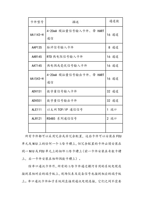
32通道
ADV551
数字量信号输出卡件
32通道
ALE111
以太网TCP/IP 通信信号
1 端口
ALR121
RS485系列通信信号
2端口
所有卡件都可以采用冗余或非冗余配置,这些卡件可以安装在FCU单元或NIU上的任何一个I/O卡槽上,但冗余配置的卡件必须安装在同一NIU或FCU单元上的相邻I/O卡槽上(前一卡件安装在奇数卡槽上,后一卡件安装在相邻偶数卡槽上)。
卡件型号描述通道数aai143h420ma模拟量信号输入卡件带hart通信16通道aap135脉冲信号输入卡件8通道aar145rtd热电阻信号输入卡件16通道aat145热电偶或毫伏信号输入卡件16通道aai543h420ma模拟量信号输出卡件带hart通信16通道adv151数字量信号输入卡件32通道adv551数字量信号输出卡件32通道ale111以太网tcpip通信信号1端口alr121rs485系列通信信号2端口所有卡件都可以采用冗余或非冗余配置这些卡件可以安装在fcu单元或niu上的任何一个io卡槽上但冗余配置的卡件必须安装在同一niu或fcu单元上的相邻io卡槽上前一卡件安装在奇数卡槽上后一卡件安装在相邻偶数卡槽上
卡件型号
描述
通道数
AAI143-H
4-20mA模拟量信号输入卡件、 带 HART 通信
16通道
AAቤተ መጻሕፍቲ ባይዱ135
脉冲信号输入卡件
8 通道
AAR145
RTD热电阻信号输入卡件
16 通道
AAT145
热电偶或毫伏信号输入卡件
16 通道
AAI543-H
4-20mA模拟量信号输出卡件、带 HART 通信
16通道
余热发电DCS硬件

余热发电技术资料余热发电硬件培训资料安徽海螺集团自动化所二○○七年六月目录第一章T2550控制器................................. 错误!未指定书签。
第一节T2550 基本单元.................................................................................... 错误!未指定书签。
第二节T2550 控制器终端单元........................................................................ 错误!未指定书签。
第三节T2550 控制器........................................................................................ 错误!未指定书签。
第二章T2550 卡件 ................................... 错误!未指定书签。
第一节 2 两通道模拟量输入卡件...................................................................... 错误!未指定书签。
第二节 2 两通道模拟量输出卡件...................................................................... 错误!未指定书签。
第三节 4 四通道模拟量输入卡件...................................................................... 错误!未指定书签。
第四节8 八通道开关量输入卡件...................................................................... 错误!未指定书签。
EPSON ETI2550SP 产品指南说明书
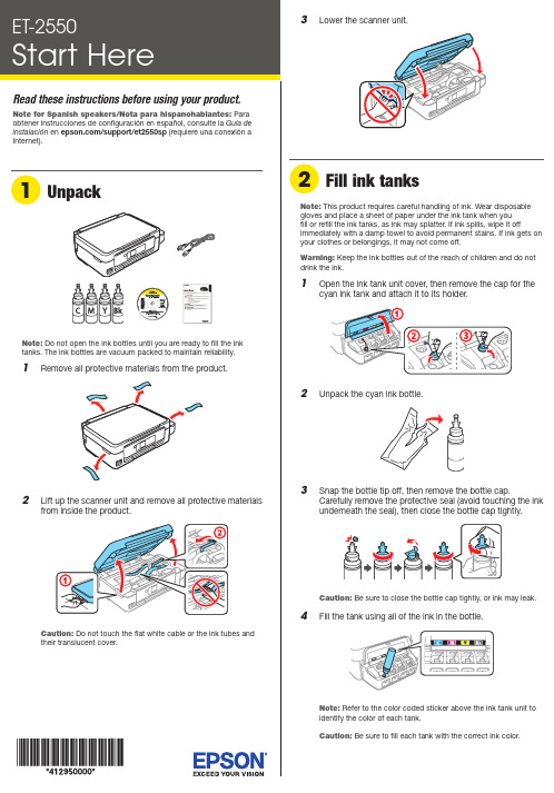
Do not open the ink bottles until you are ready to fill the ink12 W hen the message to see the setup manual is displayedon the LCD screen, press and hold the OK button for3 seconds.13 P ress the button to start charging the ink. Ink chargingtakes approximately 20 minutes. Ink charging is completewhenstops flashing.20 minutesNote: The ink bottles included with the printer are designed for printer setup and not for resale. After some ink is used for charging, the rest is available for printing.Caution: Do not turn off the product or load paper while theproduct is charging or you’ll waste ink.1 M ake sure the product is not charging. Then flip thefeeder guard forward, raise the paper support, and tilt itbackwards slightly.2 S lide the edge guide to the left.3 LMobile printing optionsTo print from a mobile device, your product must be set up forwireless printing or Wi-Fi Direct ®. See the online User’s Guide for instructions.iOS/Android ™Epson Connect™Connect wirelessly from your tablet, smartphone, or computer. Print documents and photos from across the room or around the world./iprint /connectAny problems?Network setup was unsuccessful.• M ake sure you select the right network name (SSID). The product can only connect to a network that supports 2.4 GHz.• I f you see a firewall alert message, click Unblock or Allow to let setup continue.• I f your network has security enabled, make sure you enter your network password (WEP key or WPA passphrase) correctly. Passwords must be entered in the correct case.There are lines or incorrect colors in my printouts.Run a nozzle check to see if any of the print head nozzles areclogged. Then clean the print head, if necessary. See the online User’s Guide for more information.Setup is unable to find my product after connecting it with a USB cable.Make sure the product is on and securely connected as shown:Any questions?Quick GuideBasic information and troubleshooting.User’s GuideWindows: Click the icon on your desktop or Apps screen to access the online User’s Guide .OS X: Click the icon in Applications/Epson Software/Guide to access the online User’s Guide.If you don’t have a User’s Guide icon, go to the Epson website, as described in the next column.4 S5 P6 Select the paper settings on the product’s control panel.Note: If your computer does not have a CD/DVD drive or you areusing a Mac, an Internet connection is required to obtain the product software.1 M ake sure the product is NOT CONNECTED to yourcomputer.Windows ®: If you see a Found New Hardware screen, click Cancel and disconnect the USB cable.2I nsert the product CD or download and run your product’ssoftware package:/support/et2550 (U.S.) orepson.ca/support/et2550 (Canada)3 F ollow the instructions on the screen to run the setupprogram.OS X: Make sure you install Software Updater to receive firmware and software updates for your product.4 W hen you see the Select Your Connection screen, selectone of the following:• Wireless connectionIn most cases, the software installer automatically attempts to set up your wireless connection. If setup is unsuccessful, you may need to enter your network name (SSID) and password.• Direct USB connectionM ake sure you have a USB cable (not included).5 W hen software installation is complete, restart yourcomputer.。
万向节十字轴工艺卡
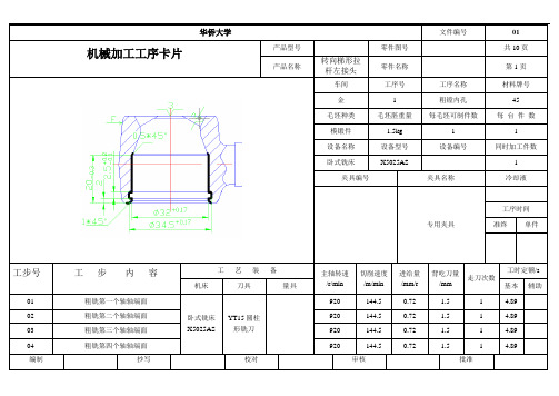
机械加工工序卡片产品型号零件图号共10页 产品名称转向梯形拉杆左接头零件名称第1页车间 工序号 工序名称 材料牌号 金 1 粗镗内孔 45 毛坯种类 毛坯胚重量 每毛坯可制件数每 台 件 数模锻件 1.5kg 1 1 设备名称 设备型号 设备编号 同时加工件数卧式铣床X5025AS1 夹具编号夹具名称冷却液专用夹具工序时间准终单件工步号工 步 内 容工 艺 装 备主轴转速 /r/min 切削速度 /m/min 进给量 /mm/r 背吃刀量/mm 走刀次数工时定额/s 机床刀具量具基本 辅助 01 粗铣第一个轴轴端面 卧式铣床X5025ASYT15圆柱形铣刀920 144.5 0.72 1.5 1 4.89 02 粗铣第二个轴轴端面 920 144.5 0.72 1.5 1 4.89 03 粗铣第三个轴轴端面 920 144.5 0.72 1.5 1 4.89 04 粗铣第四个轴轴端面920144.5 0.721.514.89编制抄写校对审核批准机械加工工序卡片产品型号零件图号共10页产品名称万向节十字轴零件名称第2页车间工序号工序名称材料牌号金05 粗车四轴外圆20CrMnTi毛坯种类毛坯胚重量每毛坯可制件数每台件数模锻件 1.5kg 1 1设备名称设备型号设备编号同时加工件数卧式车床C620-1 1夹具编号夹具名称冷却液专用夹具工序时间准终单件工步号工步内容工艺装备主轴转速/r/min 切削速度/m/min进给量/mm/r背吃刀量/mm走刀次数工时定额/s机床刀具量具基本辅助01 粗车第一个轴的外圆卧式车床C620-1YT5外圆车刀1800 147 0.3 1 1 4.8102 粗车第二个轴的外圆1800 147 0.3 1 1 4.8103 粗车第三个轴的外圆1800 147 0.3 1 1 4.8104 粗车第四个轴的外圆1800 147 0.3 1 1 4.81机械加工工序卡片产品型号零件图号共10页产品名称万向节十字轴零件名称第3页车间工序号工序名称材料牌号金06 半精车外圆20CrMnTi毛坯种类毛坯胚重量每毛坯可制件数每台件数模锻件 1.5kg 1 1设备名称设备型号设备编号同时加工件数卧式车床C620-1 1夹具编号夹具名称冷却液专用夹具工序时间准终单件工步号工步内容工艺装备主轴转速/r/min 切削速度/m/min进给量/mm/r背吃刀量/mm走刀次数工时定额/s机床刀具量具基本辅助01 半精车第一个轴的外圆卧式铣床X5025AS YT15圆柱形铣刀3200 257 0.25 0.69 1 2.6502 半精车第二个轴轴端面3200 257 0.25 0.69 1 2.6503 半精车第三个轴轴端面3200 257 0.25 0.69 1 2.6504 半精车第四个轴轴端面3200 257 0.25 0.69 1 2.65机械加工工序卡片产品型号零件图号共10页产品名称万向节十字轴零件名称第4页车间工序号工序名称材料牌号金07 半精铣端面20CrMnTi毛坯种类毛坯胚重量每毛坯可制件数每台件数模锻件 1.5kg 1 1设备名称设备型号设备编号同时加工件数卧式铣床X5025AS 1夹具编号夹具名称冷却液专用夹具工序时间准终单件工步号工步内容工艺装备主轴转速/r/min 切削速度/m/min进给量/mm/r背吃刀量/mm走刀次数工时定额/s机床刀具量具基本辅助01 半精铣第一个轴轴端面卧式铣床X5025AS YT15圆柱形铣刀1180 185 0.6 0.75 1 302 半精铣第二个轴轴端面1180 185 0.6 0.75 1 303 半精铣第三个轴轴端面1180 185 0.6 0.75 1 304 半精铣第四个轴轴端面1180 185 0.6 0.75 1 3机械加工工序卡片产品型号零件图号共10页产品名称万向节十字轴零件名称第5页车间工序号工序名称材料牌号金08 钻轴向孔20CrMnTi毛坯种类毛坯胚重量每毛坯可制件数每台件数模锻件 1.5kg 1 1设备名称设备型号设备编号同时加工件数摇臂钻床Z3040 1夹具编号夹具名称冷却液专用夹具工序时间准终单件工步号工步内容工艺装备主轴转速/r/min 切削速度/m/min进给量/mm/r背吃刀量/mm走刀次数工时定额/s机床刀具量具基本辅助01 钻第一个轴的轴向孔摇臂钻床Z3040 直柄长麻花钻Φ4mm,L=119mm,L1=78mm530 21.65 0.12 4 1 52.8802 钻第二个轴的轴向孔530 21.65 0.12 4 1 52.8803 钻第三个轴的轴向孔530 21.65 0.12 4 1 52.88机械加工工序卡片产品型号零件图号共10页产品名称万向节十字轴零件名称第6页车间工序号工序名称材料牌号金10 粗铣侧面20CrMnTi毛坯种类毛坯胚重量每毛坯可制件数每台件数模锻件 1.5kg 1 1设备名称设备型号设备编号同时加工件数卧式铣床X5025AS 1夹具编号夹具名称冷却液专用夹具工序时间准终单件工步号工步内容工艺装备主轴转速/r/min 切削速度/m/min进给量/mm/r背吃刀量/mm走刀次数工时定额/s机床刀具量具基本辅助01 粗铣侧面卧式铣床X5025AS 直柄立铣刀1500 75.4 0.24 0.4 1 3.83机械加工工序卡片产品型号零件图号共10页产品名称万向节十字轴零件名称第7页车间工序号工序名称材料牌号金03 钻孔20CrMnTi毛坯种类毛坯胚重量每毛坯可制件数每台件数模锻件 1.5kg 1 1设备名称设备型号设备编号同时加工件数摇臂钻床Z3040 1夹具编号夹具名称冷却液专用夹具工序时间准终单件工步号工步内容工艺装备主轴转速/r/min 切削速度/m/min进给量/mm/r背吃刀量/mm走刀次数工时定额/s机床刀具量具基本辅助01 钻直径为7mm深度为32mm的孔摇臂钻床Z3040Φ7mm麻花钻L=74mm,L1=34mm1072 20.2 0.15 7 1 11.94华侨大学文件编号08机械加工工序卡片产品型号零件图号共10页产品名称万向节十字轴零件名称第8页车间工序号工序名称材料牌号金12 攻丝20CrMnTi毛坯种类毛坯胚重量每毛坯可制件数每台件数模锻件 1.5kg 1 1设备名称设备型号设备编号同时加工件数摇臂钻床Z3040 1夹具编号夹具名称冷却液专用夹具工序时间准终单件工步号工步内容工艺装备主轴转速/r/min 切削速度/m/min进给量/mm/r背吃刀量/mm走刀次数工时定额/s机床刀具量具基本辅助01 攻M8内螺纹摇臂钻床M8丝锥795 19.98 1.26 0.5 1 0.59华侨大学文件编号09机械加工工序卡片产品型号零件图号共10页产品名称万向节十字轴零件名称第9页车间工序号工序名称材料牌号金16 精磨外圆20CrMnTi毛坯种类毛坯胚重量每毛坯可制件数每台件数模锻件 1.5kg 1 1设备名称设备型号设备编号同时加工件数外圆磨床MQ1320 1夹具编号夹具名称冷却液专用夹具工序时间准终单件工步号工步内容工艺装备主轴转速/r/min 切削速度/m/min进给量/mm/r背吃刀量/mm走刀次数工时定额/s机床刀具量具基本辅助01 精磨第一轴的外圆外圆磨床MQ1320砂轮d=400mmb=50mm400 31.42 0.0035 0.06 1 2.5702 精磨第二轴的外圆400 31.42 0.0035 0.06 1 2.5704 精磨第四轴的外圆400 31.42 0.0035 0.06 1 2.57编制抄写校对审核批准华侨大学文件编号10机械加工工序卡片产品型号零件图号共10页产品名称万向节十字轴零件名称第10页车间工序号工序名称材料牌号金17 精磨端面20CrMnTi毛坯种类毛坯胚重量每毛坯可制件数每台件数模锻件 1.5kg 1 1设备名称设备型号设备编号同时加工件数外圆磨床MQ1320 1夹具编号夹具名称冷却液专用夹具工序时间准终单件工步号工步内容工艺装备主轴转速/r/min 切削速度/m/min进给量/mm/r背吃刀量/mm走刀次数工时定额/s机床刀具量具基本辅助01 精磨第一轴的轴端面外圆磨床砂轮210 16.49 0.0045 0.1 1 6.3503 精磨第三轴的轴端面b=50mm 210 16.49 0.0045 0.1 1 6.3504 精磨第四轴的轴端面210 16.49 0.0045 0.1 1 6.35 编制抄写校对审核批准。
T2550_PAC介绍与选型

T 2550MODEL•Cost effective controllerProgrammable Automation Controller (PAC)Specification SheetP l a n t F l o o rVisualisationOperation ViewerStore & ForwardInformation Server Reporting ReportsOperation Server (System Platform)ValveEquipment ModulePhasesConfigurationAt the heart of the system is the LINtools configuration and engineering station. LINtools is a comprehensive set of configuration, test, documentation and commissioning tools for strategy elements distributed over the LIN control backbone. The LINtools suite includes graphical configuration of block structured continuous control, sequence control SFC’s, ladder and graphics for any LIN based product. VIEW and Online reconfiguration modes allow dynamic monitoring and editing of running databases and flow charts.LINtools follows the IEC 61131-3 standard for sequence configuration, while adopting a decoupling of continuous and sequential strategy appropriate to complex process control. LINtools is designed for simplicity and productivity. Online help, free-format text annotation and area editing are included to make LINtools easy to use and configuration easy to understand and reuse. LINtools runs on a standalone or networked PC.IEC 61131Languages appropriate for the I/O type and for the application °Function Block Diagram°Sequence Function Chart°Structured Text°Ladder Logic ControlOnline reconfigurationLarge and complex control systems are expected to serve many needs and work well for long periods without shutdown under ever varying workloads. Online reconfiguration provides a useful foundation for enhancement of a deployed control system and allows modification of the systems application software while it is running. It allows active strategy components to be modified, wrapped with additional functionality or replaced with a different implementation. The T2550 PAC has generic support for adding and hot swapping I/O. Online reconfiguration can use the same or new I/O interfaces and any internally available variables.You can tentatively add and delete function blocks and wires to create a new or improved control strategy for your application –while the process is running. You can then try and untry the strategy to ensure it is correct before final application. A secure file tracking system is provided for version control.Continuous controlContinuous strategies are configured graphically on screen using ‘block structured’ techniques implemented across the system. The control configurator supports a comprehensive library of functions together with powerful editing and compound definition facilities. Merging allows the re-use of similar sections of databases, avoiding duplication of effort. Free text can be placed on the screen or attached to function blocks for simple production of descriptive documentation.Context-sensitive help reduces the need of referring to manuals.SequenceSequences are configured graphically using Sequential Function Charts (SFCs) following the IEC 61131-3 standard. Steps initiate Actions which may be Structured Text statements (ST) or nested SFCs. Transitions determine when control passes from one step to the next. By accessing the continuous control strategy this configurator presents the available points through a menu system – eliminating the need to remember the names of points and reducing the likelihood of typing errors.The sequence configurator supports text annotation and context-sensitive help. A combination of mapping lists and generic Sequential Function Charts are available to easily duplicate identical SFC models on different units (tags).Action blockAction blocks in the continuous control strategy have their functionality defined in Ladder diagrams or Structured Text (ST) within a standard template. These are particularly useful for implementation of plant control modules.Auto I/O configurationThe instrument can automatically create its own LIN Database, including all necessary module and I/O Function Blocks, based on the I/O detected in the Base Unit. When the detection is complete, an operational database is created and runs automatically.Automatic database creation is available from within LINtools when connected to a network containing T2550 PACs. This function allows new I/O to be added to an existing configuration, on line.DocumentationLINtools provides an electronic documentation facility including the graphical representation of the control strategy and a listing of the block parameters and connections. This can be transferred across the network and output can be to a printer, Postscript or AutoCAD compatible format. Free-format user annotations can be added to complete your documentation requirements.Multi-setpoint programmerMany applications need to vary the process value over time. Temperature control is one such application in which it is very common to ‘ramp’ the process value (channel) from one level to another over a set time period using a setpoint program.The PAC provides support for multiple setpoint programs that can be run simultaneously. Each program is capable of profiling up to eight channels, with up to 32 segments per profiled channel. In addition to controlling the setpoint during each segment of the profile, the controllers can also be used to activate up to 16 digital events during a segment.The setpoint program feature enables an operator to select and run a pre-configured setpoint program. A preview facility allows the operator to view the selected program before running it. Once the program is running, the setpoint and achieved processvalues are plotted on the trend screen.Eurotherm Part No. HA029159 Issue 9 December 093PAC Specification SheetData archivingData archiving is used to copy selected parts of the history, i.e.,one or more history files (.uhh) to primary, secondary or tertiary FTP Servers..Historian store and forward‘Store and forward’ is a self healing 21 CFR Part 11 data archiving system which automatically stores data during a communication failure in the T2550 PAC and then forwards this data to theconfigured data historian server once communication is reinstated.The T2550 PAC provides dual redundant data acquisition using Secure.uhh files created at the local level, which results in a secure electronic recording system with total data integrity.Alarm managementAlarms are managed and collected within the T2550 PAC to provide features such as alarm status and priority,acknowledgement, date and time stamping at the source, as well s suppression and local message historian storage.Open communicationsThe PAC provides a special function block to define any simple serial communications protocol. This function block can be used to integrate many 3rd party devices which use ASCIIcommunications, such as bar code readers and particle counters.Direct control over transmit and receive also allows multi-node connections.HMI ReportsHMI Reports provides an intuitive reporting package to develop and print reports using the secure data from the T2550 PAC. The package includes a report studio for configuring report projects and a run-time execution module to generate and print reports in many different formats to printers and file servers, and via e-mail. HMIreports is also optionally available as a web portal.Setpoint program wizardFor ease of use, LINtools incorporates a wizard for creating a setpoint program. By following the on screen prompts and editing the parameters as required, a setpoint program can be simply and quickly created with all required blocks automatically created and added to the database.Setpoint program editorIn addition to the setpoint program wizard, programs can be created or edited off–line using the setpoint program editorsupplied with LINtools. As an ActiveX, this tool can be inserted in any of your visualization packages.Redundant recording and archivingPAC Programmable Automation Controllers have internal non-volatile flash memory for secure tamper resistant data storage,providing for redundant data logging. In addition all PACprocessors support Ethernet connectivity. As such, data stored within the internal flash memory can be configured to periodically archive to primary, secondary and tertiary FTP servers. Archiving files to FTP servers provides a secure, infinite archiving capacity.Data historianData historian is used to store PV’s, message and alarminformation in the internal flash memory in order to generate historical data in the form of a set of secure, tamper resistant history files.The following example provides estimated memory durationbased on an 8-way base logging 16 Parameters to a single group.FTP pushFor efficiency, historical data files are automatically deleted on a first in first out (FIFO) basis from the internal flash memory of the PAC (7Mb for history). In order to ensure longevity of data the PAC is able to push historical data files (.uhh) to primary,secondary or tertiary FTP servers at user defined intervals. Thus,depending on the archive strategy chosen, data is never lost. As an alternative, Eurotherm Review can be used to pull data directly from the T2550 PAC255BF base unitThe base unit is fitted with the T2550 PAC I/O controller modules plus additional I/O modules. These modules plug onto terminal units, which provide the wiring interface between the plant or machine and the I/O modules. Bases are available in 5 sizes to suit the number of modules required in a particular system.Communication between the I/O modules and the processor is effected by the use of a passive internal module I/O bus running the width of the base. Each module position is tracked separately for additional security during live replacement of I/O modules.The base consists of an aluminium extrusion, the internal I/O bus and mounting supports. It is designed to be DIN rail mounted or directly fixed to a bulkhead or mounting plate. Both base and modules can be installed horizontally or vertically.MechanicalI/O Module capacity0 46816Width (mm)36164214264467 Weight no modules (Kg)0.20.450.60.7 1.2all modules (Kg)0.5 1.3 1.7 2.1 3.7 Height:180mmDepth:102.9-132.9mm with retaining lever raised Mounting:DIN rail or Bulkhead, can be mountedhorizontally or verticallyDIN rail:Use symmetrical DIN rail to EN50022-35 x 7.5 or 35 x 15Casing:Without additional protection IP20 Ventilation space:25mm free space above and belowTermination unitsThe I/O modules are mounted on the base using terminalassemblies. Terminal assemblies provide the interface betweenthe input and output signals and the I/O modules. Terminalassemblies and I/O modules are keyed to inhibit insertion ofthe incorrect module to prevent damage to both equipmentand plant.Individual termination units provide for easy modulereplacement leaving the field wiring connected. Modules areinserted and removed from the termination unit using a unique,tool-less, locking lever system.Test disconnect unitsTerminal assemblies have an optional fuse or link (isolator or disconnect). This provides a series of connections between thecustomer terminals and the I/O module, permitting pluggablefuse or link units to be placed in series with the signal. Fuse andlink units are not interchangeable.T2550 PAC - General SpecificationsSupply voltage range:19.2 to 28.8V dcVA requirements: < 80W maximum for fully loaded rackFuse rating: 4A time lag (Not customer replaceable)IOC warm start time:12 hours without external batteriesIOC power consumption: 1.5W maximumSurge current:8A maximumModule pwr consumption:See individual module specification EnvironmentalOperating temperature:0 to 55°CStorage temperature:-25 to 85°CRelative humidity: 5 to 95% (non-condensing)RFIEMC emissions:BS EN61326-1:2006EMC immunity:BS EN61326-1:2006SafetyBS EN61010-1:2001Installation cat II, Pollution degree 2Safety earth and screen connections are madeto clearly marked earth terminals at thebottom of the baseVibrationEN60068-2 test FCVibration:IEC1131-2 section 2.1.30.075mm peak amplitude 10-57Hz;1g, 57-150HzShock:20g static shockDiagnostic LED’sDiagnostic LED’s indicate module diagnostic status.All modules: A green LED at the top indicates the moduleis powered and operating correctlyPAC analogue modules: Have red LEDs for each channel to indicatechannel failurePAC digital modules: Have Yellow LEDs for each channel to indicatethe channel state.Processor module:Primary processor and communications diagnostics are available from the LEDs on the front of the processor module. More advanced diagnostics are available remotely using LINtools monitor online over Ethernet to review the diagnostic blocks.PAC Controller module: A green LED at the top indicates themodule is powered and operating correctly Internal diagnostics: A red LED indicates failure of the internalself diagnostic routinesBattery (if installed): A green LED indicates battery health Serial communications: A yellow LED indicates communications activityORDER CODEPassivebackpaneTerminal Unitfor the T2550PAC8 Module (as shown)1616 Module6 ModuleAny type of I/O module canbe placed at any slot positionTerminal Units click into place to suitthe T2550 PAC I/O module required214mm264mm467mmModule Side View102.9mm180mm4 Module164mmTerminal Unit forT2550 PAC I/O moduleSPECIFICATIONS Mechanical DetailsCPU redundancyProcessor redundancy is available for continuous, logic and sequence control.A pair of processors operate in primary / secondary configuration with a high speed data link between them providing exact tracking of the control,logic and sequence databases. Transfer from the primary to secondary processor is bumpless.The non-active processor can be replaced while the system is running and on synchronisation it loads its strategy from the active primary processor.Redundant:< 0.6s bumpless transfer for processor and I/O Changeover time: dependant on application size Synchronisation time: dependant on application sizeProcessor SwitchoverDuring a processor switch over all outputs remain at the last value. The new primary processor begins executing is application from precisely the same point as the original processor.Each processor has its own Ethernet IP address and each redundant pair uses two neighbouring node addresses on the ELIN network. This enables the system to communicate with the primary while still continuously testing communications to both processors. On processor switch over the ELIN node address is dynamically swapped to allow SCADA applications to display and log uninterrupted data. Changeover amongst LIN nodes is transparent.The following conditions can cause the processor to switch over:Hardware failure:Failure of primary controller internal health checks.Hardware removal: Removing the primary processor will cause the secondary to take immediate control.Removing the secondary will have no effect on control but will cause a system alarm on redundant configured systems.Internal communications:Primary and secondary controllers continually monitor the communications to the I/O on the local base. Should the primary controller not be able to communicate with the I/O and the secondary can still communicate with the I/O changeover will occur.If the secondary processor observes a fault in the primary communications or can see more I/O modules the secondary processor will request a changeover.External communications:Each processor in a redundant pair continuously monitors external controller communications. Should the primary controller not be able to communicate with other declared nodes on the LIN network and the secondary can still communicate with the declared nodes a change over will occur.If the secondary processor observes that it can see more declared nodes,the secondary processor will request a changeover.Manual request:A user can request a changeover if a secondary processor is running, synchronised and healthy.Removable flash memory card:The storage of the cold start application Power supply connectionThe duplex terminal unit supports dual power supply connection. In the event of a single power supply failure both processors are still supplied allowing redundant operation to continue uninterrupted.A super capacitor maintains memory for up to 12 hours in the event of complete power failure to facilitate hot start of the processors. An external battery can be fitted to extend this back up time on the redundant system.Super cap (Processor):Maintains memory/real time clock and enables hot start for up to 12 hours in absence of battery backup inputSimplex (O base):Battery support for data in SRAM and the Real-Time Clock for a minimum of 72 hourcontinuous (5 year intermittent use)Redundant:Additional terminals for an external battery connection to support SRAM and the Real-Time ClockInternal battery type:Lithium Manganese Dioxide PA250983External rechargeable battery:Use S9537 Battery charger:Use S9538Watchdog RelaysEach processor is fitted with a single watchdog relay.Watchdog relay:SPST, 1 per CPU, connectable in parallel or seriesContact rating (resistive):24V ac/dc at 0.5A Isolation:30V ac rms or 60V dcLive plug-inProcessors and I/O modules can be replaced while powered without any disturbance to the field wiring or other inputs and outputs – reducing downtime and minimising disturbance to other signal conditioning strategies.T2550 PAC – ORDER CODEControl specificationsContinuous Database resourcesMaximum database size . . . . . . . . . . . . . . . . . . .default max values 210k bytes Database resourcesNumber of database blocks . . . . . . . . . . . . . . . . . . . . . . . . . . . . . . . . . . . . . .630Number of database templates . . . . . . . . . . . . . . . . . . . . . . . . . . . . . . . . . . . .50Number of template libraries . . . . . . . . . . . . . . . . . . . . . . . . . . . . . . . . . . . . . .32Number of external databases . . . . . . . . . . . . . . . . . . . . . . . . . . . . . . . . . . . . .32Number blocks in local Dbase cached elsewhere . . . . . . . . . . . . . . . . . .1260Number blocks in remote Dbases cached locally . . . . . . . . . . . . . . . . . . . .315Number of server tasks . . . . . . . . . . . . . . . . . . . . . . . . . . . . . . . . . . . . . . . . . . . . .6Number of field-to-field connections . . . . . . . . . . . . . . . . . . . . . . . . . . . . .1260Sequence Control ResourcesSequence memory Programme data . . . . . . . . . . . . . . . . . . . . . . . . .105k bytes SFC ResourcesNumber of root SFCs loadable . . . . . . . . . . . . . . . . . . . . . . . . . . . . . . . . . . . . .31Number of steps loadable . . . . . . . . . . . . . . . . . . . . . . . . . . . . . . . . . . . . . . . .420Number of ‘wires’ permitted going into and out of step . . . . . . . . . . . . .1407Number of transitions . . . . . . . . . . . . . . . . . . . . . . . . . . . . . . . . . . . . . . . . . . . .630Number of ‘wires’ permitted going into transitions . . . . . . . . . . . . . . . . . .840Number of action associations . . . . . . . . . . . . . . . . . . . . . . . . . . . . . . . . . .1680Number of actions . . . . . . . . . . . . . . . . . . . . . . . . . . . . . . . . . . . . . . . . . . . . . .840User TasksMultiple tasks are available to the user to tune the update rate of I/O response and the control function.User Tasks . . . . . . . . . . . . . . . . . . . . . . . . . . . . . . . . . . . . . . . . . . . . . . . . . . . . . . . .4User task update ratesTask I – Synchronous to Fast I/O . . . . . . . . . . . . . . . . . . . . . . .10ms or N*10ms Only version 2 10ms I/O types can be assigned to this task (see table below) .Task 2– Auxiliary task to task1 . . . . . . . . . . . . . . . . . . . . . . . . .10ms or N*10ms Runs at task 1 rate or integer multiple of task 1 rateTask 3– Synchronous to Standard I/O . . . . . . . . . . . . . . . .110ms or N*110ms All analogue and digital I/O types can be assigned to this taskTask 4– Auxiliary task to task3 . . . . . . . . . . . . . . . . . . . . . . .110ms or N*110ms Runs at task 3 rate or integer multiple of task 3 rate Supported I/O Module TypesThe T2550 PAC shares I/O modules with the 2500 I/O.Notes†The T2550 PAC supports only Version 1 modules in simplex operation.*Version 2 Ana Out modules can run at the 10ms task on 4 or 6-way bases. Continuous strategy function blocks categoriesF = Foundation, S = Standard, C = Control, A = AdvancedCommunicationsEthernet communicationsEthernet The PAC supports Ethernet LIN (ELIN) protocol that provides secure peer-to-peer communications between bases and to other Ethernet devices over 10/100baseT Ethernet from each processor. Simultaneously itcan support Modbus-TCP Master or Slave to other Modbus-TCP devices.ELIN portConnectors:Shielded RJ45 connector per processor Network medium:Ethernet Cat5Network type:LIN over EthernetSpeed:10/100baseTNetwork topology:Star connection to a switchLine length (maximum):100 metres, extendible by repeater Allocation of IP address:Fixed, DHCP, Link-Local, BootPBroadcast storm protection:Integrated in the processorLIN address:8-way switch-bank – Duplex (bits SW2-8)10-way switch-bank – SimplexMax numbers of slaves:16 Modbus TCP slavesSerial communicationsThird party devices such as PLCs supporting Modbus can be readily integrated into the ELIN based architecture by direct connection to T2550 PAC control units. The Modbus communications allows a T2550 PAC to be used as a gateway providing access to database elements in any ELIN node.RS422/485 serial communicationsConnector:2x RJ45 connectorComms medium:RS422 (5-wire) or RS485 (3-wire), jumper select Line impedance:120Ω-240Ω twisted pairLine length: 1220m maximum at 9600 bits/secUnits per line:16 maximum (electrical loading) expandableby use of buffersMax number of slaves:64 serial slave devicesNote:Use of a comms buffer/isolator is recommendedModbus/J-BUSProtocol:Modbus/J-BUS RTU configurable master or slave Data rate:Selectable 600-38.4k bits/secData format:8 bit, selectable parity 1/2 stop bitsModbus data tables:64, configurable as registers or bits Maximum table length: 200 registers or 999 bitsRedundancy:Modbus communications are supported bythe PAC in simplex and redundant mode3 GWF may be run simultaneously1x Modbus TCP master1x TCP slave1x Modbus RTU slave or masterMax (GWF) file size: 20k bytesProfibusPhysical medium:2-wire, RS485Connectors:Single 9-way D-typeData rate:Determined by Profibus master, 12MB max. Isolation:50V dc; 30V acOpen communicationProtocol:Device drivenData rate:1200 to 38.4k bits/secData format:7 or 8 data bits, none/even/odd parity,1 or2 stop bitsORDER CODEI/O ModuleFuseDisconnectorsHealth StatusExternal Battery ConnectorSerial Communications Port24V dcand Power (Terminal Unit)I/O Status2500MF-A Two channel analogue inputThis analogue input module is used to monitor analogue signals from a wide range of plant sensors. The mA and TC inputs each require the appropriate terminal unit.The second channel of the AI2 has a special high impedance range for use with zirconia probe inputs.No of channels: 2Input types: TC, RTD, Volts, mA, mV, Potentiometer, Pyrometer, Zirconia probemV range: -150mV to +150mV at input impedance >100MΩmA range: -22mA to +22mA with 5Ω burden in the terminal unitVolts range: -10.2V to +10.2V at input impedance 303kΩ RTD support: Support for 2, 3 and 4 wire resistance thermometer devicesOhms range: 0 to 600Ω 3- or 4-wire lead compensation Hi Ohms range: 0 to 5kΩ 3- or 4-wire lead compensation Pot range: 5% to 95% ‘rotation’ of 100Ω to 5kΩ pot Resolution: Better than 0.001% of range Linearity:Better than 0.003% of range Input filtering: OFF to 999.9 secondsInput accuracy: Electrical input factory calibrated to better than 0.1% of readingSystem isolation: Reinforced, 264V ac maximumChannel isolation: Reinforced, 264V ac maximum between thermocouple channelsFunctional:264V ac maximum between RTD, volts and mA Series mode rejection:60dB (50-60Hz, 1mA rms)Common mode rejection:120dB (50-5kHz, 50V rms)Power consumption: 2W maximumTC Input specification Linearisation types: J, K, L, R, B, N, T, S, C, PL2, PT100, Linear, SqRoot, plus customCJC system:Measured by RTD fitted on terminal unit Initial CJC accuracy: ±0.5°C typical (±1°C maximum)CJC rejection:Better than 30:1 over -10°C to +70°CNote:User calibration options can improve performance, limited only by noise and non-linearity.2500MF-C Three channel analogue inputProvides three isolated current input channels specifically designed to meet the requirements of modern two wire transmitters. Each channel has its own isolated 24V supply for transmitter excitation.Each channel’s 24V dc supply is protected against short circuit and utilises a sophisticated trip and try system in which the module senses over current and cuts the power. After a period the circuit checks for continued circuit malfunction.The module can be optionally fitted with disconnects to allow isolation of an individual input to allow work on the loop to continue safely.No of channels: 3Input range:-28mA to +28mAResolution: Better than 1uA (16 bits with 1.6 sec filter time)Linearity:Better than 10uAInitial accuracy: Factory calibrated to better than ±0.1% of reading Input filtering:OFF to 999.9 secondsBurden resistance: 60Ω nominal, 50mA max currentChannel PSU: 22-25V dc, current limited 30mA nominal, self-resettingSystem isolation: Reinforced, 264V ac maximum Channel isolation: Functional, 50V ac maximum Power consumption:4W maximumNotes:er calibration options can improve performance, limited only by noise and non-linearity.2.Total burden can be increased to 250Ω or HART by cutting a link track on the terminal unit.AI2 – ORDER CODEAI3 – ORDER CODE2500MF-D Four channel analogue inputThis analogue input module is used to monitor analogue signals from a wide range of plant sensors. The mA and TC inputs each require the appropriate Terminal Unit.No of channels: 4Input types: TC, mV, mA, PyrometermV range: -150 - +150mV at input impedance >100MΩ mA range: -22 - +22mA with 5Ω burden in the terminal unit Resolution: Better than 0.001% of range Input filtering:OFF to 999.9 secondsInitial input accuracy: Electrical Input Factory Calibrated to better than 0.1% of readingSystem Isolation: Reinforced, 264V ac maximumChannel isolation: Functional, 264V ac maximum separating Ch1and Ch2 from Ch3 and Ch4Series mode rejection:60dB (50-60Hz, 1mA rms)Common mode rejection:120dB (50-5kHz, 50V rms)Power consumption: 2W maximumTC Input specification Linearisation types: J, K, L, R, B, N, T, S, C, PL2, linear, SqRoot, plus customCJC system:Measured by RTD fitted on terminal unit Initial CJC accuracy: ±0.5°C typical (±1°C maximum)CJC rejection:Better than 30:1 over -10°C to +70°CNotes:er calibration options can improve performance, limited only by noiseand non-linearity.2.Wiring care and sensor choice should be used to prevent ground loops when using non-isolated TC’s.2500MF-E Two channel analogue outputThis analogue output module provides two isolated analogue output channels. Each output can be independently configured for current or voltage mode.The module can be optionally fitted with disconnects to allow isolation of an individual output to allow work on the individual loop to continue safely.No of channels: 2Current output: -0.1 to 20.5mA; 10V dc max. compliance with total burden less than 500ΩVoltage output:0 to 10V dc; 20mA max. compliance with total load greater than 500ohms-0.5 to 10.5 V dc; 8mA max. compliance with total load greater than 1500ΩResolution:Better than 1 part in 10,000 (15 bit typical)System isolation: Reinforced, 264V acChannel isolation: Functional, 264V ac maximum Power consumption:2.2W maximumAI4 – ORDER CODEAO2 – ORDER CODE。
Panduit CT-2525CH、CT-2550CH和CT-2570CH紧固头说明书
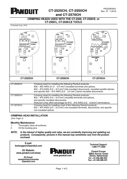
CT-2525CH, CT-2550CH and CT-2570CHPA25383A01 Rev. 07 1-2019CRIMPING HEADS USED WITH THE CT-2500, CT-2500/E; orCT-2500/L, CT-2500/LE TOOLS© Panduit Corp. 2019CT-2525CH CT-2550CH CT-2570CHCT-2525CH Crimping head for installing the following Panduit products:#26 – #22 AWG (0,14 – 0,5 mm2)insulated terminals and splices,#22 – #10 AWG (0,5 – 6,0 mm2) fully insulated disconnects, insulated parallel splices;and specific #22 – #14 AWG (0,5 – 2,5 mm2) barrel insulated disconnects.CT-2550CH Crimping head for installing the following Panduit products:#22 – #10 AWG (0,5 – 6,0 mm2) insulated terminals and splices;and specific insulated disconnects.Reduced crimp effort advantage for #12 – #10 AWG (4,0 – 6,0mm2) terminations.CT-2570CH Crimping head for installing most of the following Panduit products:#22 – #10 AWG (0,5 – 6,0 mm2) non-insulated terminals, disconnects; and specificnon-insulated splices.CRIMPING HEAD INSTALLATION(See Page 2)Monthly Maintenance1. Thoroughly clean all surfaces.2. Oil the locating pins.NOTE: In the interest of higher quality and value, we are constantly improving and updating our products. Consequently, pictures in this manual may sometimes vary from the productenclosed.E-mail:EU Website:/emeaEU Email:emeatoolservicecenter@Technical Support:1-800-777-3300Panduit EuropeEMEA Service CenterAlmelo, NetherlandsTel: +31-546-580-452Fax: +31-546-580-441© Panduit Corp. 2019INSTALLATION INSTRUCTIONS CT-2525CH, CT-2550CHand CT-2570CHCRIMPING HEAD INSTALLATION1. Rotate crimping head adapter fully --clockwise (see Figure 1).2. Press retract slide to lower pistoncompletely.3. Pull out the pins for mounting adifferent crimping head on theadapter.4. Before installing a different crimpinghead, slide the crimp dies to the fullopen position. Lock the head withthe locating pins (see Figure 2),paying attention that the pins arelocked securely before starting.5. The crimping cycle is terminatedwhen the dies are completely closedand the maximum crimping force isreached, which is indicated by theauto retraction of the piston.Refer to the CT-2500, CT-2500/E(PA25346A01); or CT-2500/L,CT-2500/LE (PA28113A01) OperationManual for complete tool and crimpinghead instructions.ATTENTION: The crimping process can be interrupted at any time by releasing the trigger.After having terminated the crimping process and prior to changing the heads, remove battery to avoid unintended starts.DIE CLOSURE GO / NO GO GAGE MEMBERS – CT-2525CHCRIMP POCKET ENGLISH GO / NO GO GAGE MEMBERS METRIC GO / NO GO GAGE MEMBERS AWG / mm2“G” Dia. (GO) “NG” Dia. (NO GO) “G” Dia. (GO) “NG” Dia. (NO GO) Pocket “A” .0835” .091” 2,12 mm 2,31 mm22 – 14 / 0,5 – 2,5 .0765” .084” 1,94 mm 2,13 mm12 – 10 / 4,0 – 6,0 .1005” .108” 2,55 mm 2,74 mmDIE CLOSURE GO / NO GO GAGE MEMBERS – CT-2550CHCRIMP POCKET ENGLISH GO / NO GO GAGE MEMBERS METRIC GO / NO GO GAGE MEMBERS AWG / mm2“G” Dia. (GO) “NG” Dia. (NO GO) “G” Dia. (GO) “NG” Dia. (NO GO) 22 – 14 / 0,5 – 2,5 .1015” .108” 2,57 mm 2,74 mm12 – 10 / 4,0 – 6,0 .1475” .154” 3,74 mm 3,91 mmDIE CLOSURE GO / NO GO GAGE MEMBERS – CT-2570CHCRIMP POCKET ENGLISH GO / NO GO GAGE MEMBERS METRIC GO / NO GO GAGE MEMBERS AWG / mm2“G” Dia. (GO) “NG” Dia. (NO GO) “G” Dia. (GO) “NG” Dia. (NO GO) 22 – 18 / 0,5 – 1,5 .0515” .060” 1,31 mm 1,53 mm16 – 14 / 1,5 – 2,5 .0735” .082” 1,87 mm 2,09 mm12 – 10 / 4,0 – 6,0 .0995” .108” 2,53 mm 2,75 mm。
WTY-871技术及使用说明书 V1.01
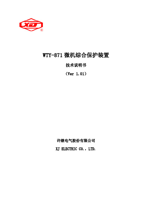
量值 线路
按 “右”键选
择‘设置’菜单
? ?
设置 调试 版本
选择装置类型
NO 简称 1 ZZLX 装置类型
量值 厂用变
按“确定”键 进入‘设置’菜单
按“确定”键 固化并保存 (若不保存,按“取 消”键放弃固化)
请选择子菜单 参数 通信 时钟 1 密码 电度 按确定进入 ,按取消返回
技术指标 .......................................................................................................................................................................... 3 2.1 基本电气参数 ......................................................................................................................................................... 3 2.1.1 额定交流数据 ................................................................................................................................................ 3 2.1.2 额定电源数据 ................................................................................................................................................ 3 2.1.3 功率消耗 ........................................................................................................................................................ 3 2.1.4 过载能力 ........................................................................................................................................................ 3 2.2 主要技术指标 ......................................................................................................................................................... 3 2.2.1 保护定值整定范围及误差 ............................................................................................................................ 3 2.2.2 测量精度 ........................................................................................................................................................ 4 2.2.3 记录容量 ........................................................................................................................................................ 4 2.2.4 触点容量 ........................................................................................................................................................ 4 2.2.5 绝缘性能 ........................................................................................................................................................ 4 2.2.6 机械性能 ........................................................................................................................................................ 4 2.2.7 抗电气干扰性能 ............................................................................................................................................ 5 2.3 环境条件 ................................................................................................................................................................. 5 2.4 通信接口 ................................................................................................................................................................. 5
CJT长江连接器A2550系列

Current rating:3A AC,DC Voltage rating:300V AC,DCTemperature range:-40°C~+105°CContact resistance:5m Ω Max.Insulation resistance:1000M Ω Min.Withstanding voltage:1100V AC/minute*Compliant with RoHS and REACH**Meet the HF/Halogen Free,need to customize**Contact CJT for details*StandardsE326732Contact LayoutUnit:mmUse With CJT A2550 series Housing :Reference Informations:*Used in CJT A2550 series HousingUnit:mmReference Informations:*Used in CJT A2550 series HousingUnit:mmUse With CJT A2550 series Housing :Single Row Dual Row A2550H-2, A2550HA-2Use With CJT A2550 series Housing :Single Row A2550H, A2550HA, A2550HB, A2550H-AA2550H-B, A2550H-C, A2550H-C1, A2550H-DDual Row A2550H-2, A2550HA-2A2550H-E, A2550H-F, A2550H-JA2550H, A2550HA, A2550HB, A2550H-AA2550H-B, A2550H-C, A2550H-C1, A2550H-DA2550H-E, A2550H-F, A2550H-JReference Informations:*Used in CJT A2550 series HousingUse With CJT A2550 series Housing :Single RowA2550H-G, A2550H-H, A2550H-IUse With CJT A2550 series Housing :Use With CJT A2550 series Housing :Unit:mmReference Informations:*Used in CJT A2550HK series HousingUnit:mmSingle Row A2550HK-2Dual RowA2550HKReference Informations:*Used in CJT A2550 series HousingUse With CJT A2550 series Housing :Single Row A2550H, A2550H-D A2550H-2Dual RowReference Informations:Unit:mmReference Informations:*Used in FFC WireUnit:mmP.C.B LAYOUTReference Informations:Unit:mmP.C.B LAYOUTReference Informations:*Used in FFC WireUnit:mmP.C.B LAYOUTReference Informations:Unit:mmP.C.B LAYOUTUnit:mmReference Informations:*Used in CJT A2550HM A2550HMAA2550H-M1 A2550H-M3 series HousingReference Informations:Unit:mmUnit:mmReference Informations:*Used in FFC WireReference Informations:*Used in FFC WireUnit:mmP.C.B LAYOUTReference Informations:*Used in FFC WireUnit:mmP.C.B LAYOUTReference Informations:Unit:mmReference Informations:Ordering Information & Dimensions:Reference Informations:*Material:PBT30%GF,UL94V-0*Suitable CJT A2550 series Terminal (A2550-T(-H), A2550-T(-H)-CR, A2550-T-A, A2550-T-C,)*Mates with CJT A2549 series Single Row Wafer (A2549WVB, A2549WRB)Ordering Information & Dimensions:Reference Informations:*Material:PBT30%GF,UL94V-0*Suitable CJT A2550 series Terminal (A2550-T(-H), A2550-T(-H)-CR, A2550-T-A, A2550-T-C,)*Mates with CJT A2549 series Single Row Wafer (A2549WVB, A2549WRB)Ordering Information & Dimensions:Reference Informations:*Material:PBT30%GF,UL94V-0Ordering Information & Dimensions:Reference Informations:*Material:PBT30%GF,UL94V-0Ordering Information & Dimensions:Ordering Information & Dimensions:Reference Informations:*Material:PBT30%GF,UL94V-0*Suitable CJT A2550 series Terminal (A2550-T(-H), A2550-T(-H)-CR,Reference Informations:*Material:PBT30%GF,UL94V-0Reference Informations:*Material:PBT30%GF,UL94V-0Ordering Information & Dimensions:Unit: mmReference Informations:*Material:PBT30%GF,UL94V-0*Suitable CJT A2550 series Terminal (A2550-T-B)*Mates with CJT A2541 series Wafer *Color:BlackOrdering Information & Dimensions:Reference Informations:*Material:PBT30%GF,UL94V-0*Suitable CJT A2550 series Terminal (A2550-T-B)*Mates with CJT A2541 series Wafer *Color:BlackUnit: mmOrdering Information & Dimensions:Ordering Information & Dimensions:*Material:PBT30%GF,UL94V-0*Suitable CJT A2550 series Terminal (A2550-T-B)*Mates with CJT A2549 series Wafer or A2547WVE, A2547WRE series Wafer *Color:BlackUnit: mmOrdering Information & Dimensions:Reference Informations:*Material:Nylon 66,UL94V-0*Terminal Material:Phosphor Bronze/Tin over Nickel *Used in FFC Wire *Color:BlueOrdering Information:A2550HD-XP - **1.Part No.2.Finish:(blank):Phosphor Bronze/Tin over Nickel GP:Phosphor Bronze/Gold over Nickel1 2*Material:PBT30%GF,UL94V-0*Suitable CJT A2550 series Terminal (A2550-T-K)*Color:Blue2P~7P8P~36PReference Informations:*Material:PBT30%GF,UL94V-0*Suitable CJT A2550 series Terminal (A2550-T-K)*Color:BlueReference Informations:*Material:PBT30%GF , UL94V-0*Suitable CJT A2547-E series Terminal*Mates with CJT A2547HM A2550HM series Housing or A2547 series single row Wafer *Color:BlackReference Informations:*Material:PBT30%GF , UL94V-0*Suitable CJT A2547-E series Terminal*Mates with CJT A2547 series single row Wafer *Color:Black2P3P Reference Informations:*Material:PBT30%GF , UL94V-0*Suitable CJT A2550-E , A2550M-D series Terminal *Color:Black。
测速与超速保护卡FW345使用手册
测速与超速保护卡FW3451基本说明FW345智能型汽轮机测速与超速保护卡,是汽轮机控制系统的专用模块。
通过与TB345端子板连接,构成DEH系统的测速与超速保护I/O单元。
FW345接收现场的汽轮机测速装置发来的电信号得到汽轮机的精确转速,同时接收开关跳闸和紧急停车两个DI干触点信号和上位机指令,进而发出快速可靠的汽轮机超速报警信号。
该信号通过继电器输出驱动超速保护电磁阀和危急遮断电磁阀,实现汽轮机超速限制、保护功能。
本卡件具备带电插拔功能,可在系统带电的情况下直接插拔卡件,不会影响系统的正常运行。
FW345需要在主控制卡为FW247的系统中使用。
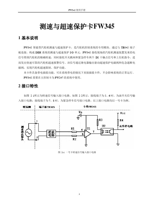
2接口特性如图 2-1所示为转速信号输入接口电路。
如图 2-2所示,接线端子为5、6时,为油开关信号输入接口电路;接线端子为7、8时,为紧急停车信号接口电路。
以上接口电路均以一号卡为例。
图2-1 一号卡转速信号输入接口电路1图 2-2 一号卡油开关(紧急停车)信号输入接口电路如图 2-3所示,端子为25、26时为超速103%保护“三选二”报警输出接口电路,端子为27、28时为超速110%保护“三选二”报警输出接口电路。
图2-3 3选2 报警输出接口电路3使用说明卡件结构简图,如图 3-1所示:2图3-1 FW345结构简图3.1LED指示灯说明表 3-1 指示灯说明名称含义状态FAIL 卡件故障指示灯正常情况下灭。
当卡件故障或者复位时,FAIL 灯亮。
端子板24V未接,FAIL灯也会点亮RUN 卡件程序运行指示灯正常情况下RUN闪烁WORK 卡件工作指示灯正常情况下常亮COM 卡件通讯指示灯正常情况下闪烁POWER 卡件内部24V指示灯正常情况下常亮SLIP 开关跳闸指示灯跳闸点亮,反之灭TRIP 紧急停车指示灯系统紧急停车点亮,反之灭103A 103%报警输出第一路报警时点亮,反之灭103B 103%报警输出第二路报警时点亮,反之灭110A 110%报警输出第一路报警时点亮,反之灭110B 110%报警输出第二路报警时点亮,反之灭33.2跳线3.2.1跳线说明表 3-2 FW345跳线设置J501 程序下载接口,下载时连接下载线。
富士通PRIMERGY CX2550 M4多节点服务器说明书

Data SheetFUJITSU PRIMERGY CX2550 M4 多節點伺服器PRIMERGY CX400 M4 適用之雲端 / 高效能運算(HPC) 優化伺服器節點FUJITSU PRIMERGY伺服器能執行任何工作負載與因應瞬息萬變的業務需求。
隨著業務拓展,對於應用的需求也隨之升高。
每項需求均需佔用資源,因此必須尋找能夠優化運算的方式,為使用者提供更佳服務。
PRIMERGY系統具備完整的產品組合,包含適用於遠端分公司的PRIMERGY直立式伺服器、萬用機架式伺服器,以及密度最佳化的橫向擴展伺服器,有助於提升運算能力,配合業務需求。
經得起商業考驗的創新系列產品,以其高效率降低營運的成本與複雜程度,使日常運作更加靈活,並可無縫整合,助您專注在核心業務上。
FUJITSU PRIMERGY CX多節點系統是雲端、超融合式與高效能運算解決方案的理想平台,提供資料中心與分公司大量的運算效能,以執行虛擬化環境、複雜運算、伺服器整併及高可用性情境。
PRIMERGY CX2550 M4FUJITSU PRIMERGY CX2550 M4 伺服器為小巧的伺服器節點,僅用2U(PRIMERGY CX400 M4)便可達最多四座獨立伺服器的最高運算密度。
此款雙插槽伺服器節點採用最新的Intel® Xeon® Processor Scalable Family及16 DIMM插槽(最高可達2,048 GB的DDR4記憶體)。
採用雙儲存磁碟配置的CX2550 M4適用於主流企業的工作負載、雲端與高效能運算情境。
此款伺服器節點也進一步提供多種類的模組方案,以滿足未來的個別需求;除內建的基本LAN功能外,此款節點也額外提供2個PCIe Gen3 x16插槽,及選配的CPU 直接高速互連(Intel® Omni-Path Architecture),具備低通信延遲、低功耗、高處理能力的優點。
A2系统介绍精选PPT

FOXBORO A2 –T2500
T2500模件-AI2
14
FOXBORO A2 –T2500
T2500模件-AI3
15
FOXBORO A2 –T2500
T2500模件-AI4
16
FOXBORO A2 –T2500
T2500模件-AO2
17
FOXBORO A2 –T2500
T2500模件-DI4
FOXBORO A2 系统介绍
1
目的: 1、了解FOXBORO A2系列产品 2、了解FOXBORO A2系统性能 3、能够做出一个系统FOXBORO A2配置
2
FOXBORO A2结构
OP
RT
DS
Historian
ALIN
T640
Modbus/TCP
T2500
100M ETHERNET Network
Redundant
25
FOXBORO A2 –T2550
26
FOXBORO A2 –T2550
64M FLASH MEMORY
27
FOXBORO A2 –T2550
28
FOXBORO A2 –T2550
完全开放协议: A、ELIN B、Modbus/TCP C、Modbus E、Profibus—DP F、Devicenet
ELIN
Modbus/TCP
ELIN
T2550
T940
ELIN
T800
3
FOXBORO A2网络结构
OP
RT
DS
Historian
ALIN
T640
Modbus/TCP
T2500
100M ETHERNET Network
2550注意事项
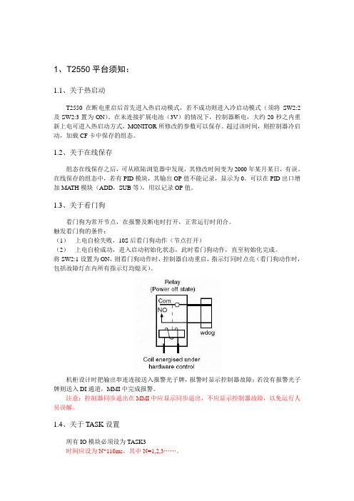
1、T2550平台须知:1.1、关于热启动T2550在断电重启后首先进入热启动模式,若不成功则进入冷启动模式(须将SW2:2及SW2:3置为ON)。
在未连接扩展电池(3V)的情况下,控制器断电,大约20秒之内重新上电可进入热启动方式,MONITOR所修改的参数可以保存。
超过该时间,则控制器冷启动,加载CF卡中保存的组态。
1.2、关于在线保存组态在线保存之后,可从欧陆浏览器中发现,其修改时间变为2000年某月某日,有误。
在线保存的组态中,若有PID模块,其输出OP值不能记录,显示为0。
可以在PID出口增加MA TH模块(ADD,SUB等),用以记录OP值。
1.3、关于看门狗看门狗为常开节点,在报警及断电时打开,正常运行时闭合。
触发看门狗的条件:(1)上电自检失败,10S后看门狗动作(节点打开)(2)上电自检成功,进入启动初始化状态,此时看门狗动作,直至初始化完成。
将SW2:1设置为ON,则看门狗动作时,控制器自动重启,指示灯同时点亮(看门狗动作时,包括故障灯在内所有指示灯均熄灭)。
机柜设计时把输出串连连接送入报警光子牌,报警时显示控制器故障;若没有报警光子牌则送入DI通道,MMI中完成报警。
注意:控制器同步退出在MMI中应显示同步退出,不应显示控制器故障,以免运行人员误解。
1.4、关于TASK设置所有IO模块必须设为TASK3时间应设为N*110ms,其中N=1,2,3……。
1.5、关于T2550容量控制器容量限制如上图左,SFC容量限制如上图右。
♦DBSIZE限制为85,实际应为83左右。
连线数限制为510,实际使用中可以略超出一些。
组态过大有可能出现NOACTION、连线失效等情况。
连线失效一般出现在远传至本地的模块上(该连线的扫描等级最低)。
♦SFC中,STEP限制为212,MAXSFCsz限制为59,这两项容易超限,导致顺控无法正常运行。
♦应用中FEA TT数量超限是导致控制器不能正常运行的重要原因。
华硕 PRIMERGY TX2550 M7 台式机或4U 机柜服务器说明书

PRIMERGY TX2550 M7Tower or 4U Rack server<-- order code E-part (bold) -- <-- order code L-part (bold)<-- "name" of this part<--description of this part, in same cases as well description of content <--requires a free PCIe slot --> means total amount of PCIe slots reduced <--indicates how often this part can be configured in the related Server<-- "PYB" order code (bold) for BTO(Built to Order) part <-- "PY-" order code (bold) for Loose delivery part <-- Limitation for this partFujitsu is providing the content of this document with very high accuracy. In case you identify a mistake, we would kindly encourage you to inform us. We kindly ask for understanding, that errors still may occur and that Fujitsu may change this document without noticeText fields with grey color offer extra information for related topics (e.g prerequesites, technical back ground, configuration rules, limitations, …PCI Riser left (CPU2) PCI Riser right (CPU1)The front views shown below represent all possible drive options; they do not represent the base units.For information on base units and HD drive cage for each drive option, please see chapter “base” and "HD_cage"16x HDDs/SSDs + 8xHDDs/SSDs/NVMes24x HDDs/SSDs 24x HDDs/SSDs + 8xHDDs/SSDs/NVMes12x HDDs/SSDs4x HDDs/SSDs8x HDDs/SSDs8x HDDs/SSDs16x HDDs/SSDsXCC MCCXCC MCC MCC XCC MCC MCC MCC MCC XCC MCC XCC MCC MCC MCC MCC MCC MCCPRIMERGY TX2550 M7System configurator andorder information guidePreferred slots for controller assignementGeneral drive numbering schemeRear side view (incl. riser card option; refer to sheet "Description" for details)TX2550 M7 front views of expandable base units and corresponding HD drive cage options:1x 9.5mm bay is available for a slim optical drive in the upper drive area.1x HBA- or RAID-Controller. Refer to section "RAID" for options. onboard SATA(Max. qty. for Disk is eight.)3x 1.6x5.25" bays are available for an optical and/or backup drives in the upper drive area.FHD drive cage is a metal box providing bays for 3.5" HDDs or 2.5" HDDs/SSDs/PCIe-SSDs. Choose out of thefollowing HD cage upgrade kits, depending on pre-selected TX2550 M7 base unit and the targeted configuration. Each upgrade kit contains all relevant parts such as metal cage, backplane, cables and mounting material.Upgrade kits for the upper drive area require the completion of the mid drive area.Up to 3x 1.6x5.25" bays are available in the upper drive area for an ODD and/or backup drive configurations; in the 12x3.5" configuration, a 9.5mm bay is available for a slim ODD. Refer to sections "ODD" and "backup" for details.Upgrade kits are available either ex-factory (E-codes) or as loose delivery party (L-codes).RAID configurations are recommendations; refer to section "RAID" for available options.Please refer to “Upgrade kit for the upper drive area with PYT2557TBN/ PYT2557R2N/ PYT2557TCN/ PYT2557RAN3x 1.6x5.25" bays are available for an optical and/or backup drives in the upper drive area.3x 1.6x5.25" bays are available for an optical and/or backup drives in the upper drive area.1x HBA- or RAID-Controller. Refer to section "RAID" for options. onboard SATA(Max. qty. for Disk is eight.)The mix configuration informationPRIMERGY TX2550 M7System configurator and order information guidewill be EOL in CQ2'24S26361-F3267-E2S26361-F3267-L2DVD-RW supermulti SATA all formats, DUAL/DL, DVD-RAM only W2K, W3K and LinuxDVD-RW supermulti ultra slim all formats, DUAL/DL, DVD-RAM only W2K, W3K andWith most configurations the TX2550 M7 offers 3 x 1.6” bay in the accessible drives area located at the top of the Tower Server (or at the right side of the Rack) for various ODD and or backup drives. Depending on the HDD drive configuration there may be some or all of these 1.6” bays already occupied-please find the number of available bays and the size listed as point 3)at each of the drive bundles. All bundles with limitations are highlighted with 2 exclamation marks in the front (e.g. "!! 1x 9.5mm ...")PCI riser card configurationStandard Model only(PYT2557TAN/PYT2557TBN/PYT2557TCN/PYT2557R3N/PYT2557R2N/PYT2557RAN)6x PCIe slots are on board, with optional PCIe riser card up to 10x PCIe slots are available.You can choose between 6 different PCI riser card (Options a – f), depending on the selected PCIe card or GPGPU. Please refer to the tables below for more details and for the installation rules.Required 'Configuration Thermal Design 30°C(CTD30)[PYBETA1]'Possible configurations with each PCIe riser card option*Support brackets are required for the cooling of passively cooled FH GPUs.PRIMERGY TX2550 M7System configurator andorder information guidePRIMERGY TX2550 M7System configurator andorder information guidePRIMERGY TX2550 M7System configurator andorder information guide。
欧陆系统运行常见问题分析及解决办法

余热发电DCS系统几个典型问题分析与解决办法【问题现象一】:全厂停电(包括DCS)后再次上电时,余热发电相关电机、水泵类设备部分或全部自动启动。
案例:某子公司由于总降故障导致全厂停电,由于处理故障时间较长,UPS蓄电池电量耗光,导致控制器DPU断电。
故障排除后,工作人员再次送电,这时,现场高低压设备均正常,DCS控制器也上电正常,控制器得电后开始自动下装程序,随后现场人员突然发现锅炉除灰设备、部分水泵电机先后自动开启,但是中控操作员实际并未对相关设备进行操作,经仔细检查,发现开机指令实际是程序自动发出的。
原因分析:正在运行的控制器突然断电时,当前正在运行程序中的实时数据会丢失,再次上电后程序的实时数据会回到该程序最后一次在线保存时的瞬时数据,若该程序最后一次在线保存时部分设备在正常运行,那么断电后再次上电的一瞬间,这些设备的驱动指令输出都是常“1”状态,如果此时现场设备也处于备妥正常状态,那么这些设备就会自动启动。
解决办法:有两种方法可以处理:第一种、有计划的处理,可根据公司的检修计划来安排处理,在电厂所有电机、水泵类设备都停机,同时将所有DO电动阀(特别是废气挡板)都切换到手动状态,然后将所有控制器的程序进行一次在线保存操作,即可解决此问题。
第二种、紧急情况下处理,紧急情况在此是指非计划性全厂停电,如果出现全厂停电的情况,首先要看给DCS机柜供电的UPS是否带电,若带电,则按照第一种方法处理;若UPS同时断电,应在DCS控制器上电前将所有高、低压设备(低压柜或者现场控制柜)及DO挡板切换到现场(非远方)位置,待上电后对所有控制器进行一次在线保存操作即可解决问题。
附:程序在线保存方法首先,进入需要在线保存程序的文件夹(比如D:/***),打开程序,如AQC锅炉程序,T2550_16.DBF(1)程序在线分两种版本若为新版本,则在程序主界面工具栏点击图标, 如上图红色方框所示位置,弹出如下图所示窗口:点击上图中的按钮‘Open’,会出现如下图所示窗口:在上图中选中“T2550_16”控制器,点击“Open”,这样程序就处于在线状态。
柯尼卡美能达bizhub C250_C252维修手册中文
柯尼卡美能达bizhub C250_C252维修手册中文2006.122006.12Ver. 3.0Ver. 3.02006.12 Ver. 3.02006.12 Ver. 3.0?? 2006 ?? 2006DD4038PC3-0800DD4038PC3-0800G4G4i现场维修总目录安全和重要警告事项 ..................................................................... ....................................S-1重要注意事项 ..................................................................... .........................................S-1危险事项、警告和注意的描述 ..................................................................... ................S-1安全警告 ..................................................................... ................................................S-2机器上的警告标识 ..................................................................... ................................S-18当发生意外时采取的措施 ..................................................................... ..........................S-20维修手册的构成 ..................................................................... ..........................................C-1维修手册的注释 ................................................................. ..............................................C-2bizhubC250/C252 主机概述.................................................................. ...............................................................1维修...................................................................... ...........................................................9调整/设置...................................................................... .............................................169故障排除...................................................................... ...............................................397附标准录...................................................................... .......................................................517控制器概述.................................................................. ...............................................................1维修...................................................................... ...........................................................3调整/设置...................................................................... ...............................................37故障排除...................................................................... .................................................39DF-601概述...................................................................... ...........................................................1维修...................................................................... ...........................................................5调整/设置.....................................................................................................................13故障排除...................................................................... .................................................29PC-103/PC-203概述.................................................................. ...............................................................1维修...................................................................... ...........................................................3调整/设置...................................................................... ...............................................13故障排除...................................................................... .................................................19PC-403概述...................................................................... ...........................................................1维修...................................................................... ...........................................................3调整/设置...................................................................... ...............................................17故障排除...................................................................... .................................................25bizhubC250_FS_Total_E TOC.fm Page i Friday January 5 2007 4:11 PMiiAD-503概述...................................................................... ..........................................................1维修...................................................................... ..........................................................3调整/设置...................................................................... ................................................7故障排除...................................................................... .................................................11FS-501概述...................................................................... ..........................................................1维修.................................................................. ..............................................................5调整/设置...................................................................... ................................................9故障排除...................................................................... .................................................19FS-514/PK-510/OT-601概述.................................................................. ..............................................................1维修...................................................................... ..........................................................7调整/设置...................................................................... ..............................................45故障排除...................................................................... .................................................59MT-501 概述...................................................................... ..........................................................1维修...................................................................... ..........................................................3调整/设置...................................................................... ................................................7故障排除...................................................................... .................................................13SD-503概述...................................................................... ..........................................................1维/修...................................................................... ..........................................................3调整设置...................................................................... ..............................................25故障排除...................................................................... .................................................37FS-603概述...................................................................... ..........................................................1维修...................................................................... ..........................................................5调整/设置...................................................................... ..............................................23故障排除...................................................................... .................................................51bizhubC250_FS_Total_E TOC.fm Page ii Friday January 5 2007 4:11 PM安全和重要警告事项S-1在进行维修工作前请仔细阅读如下所述的安全和重要警告事项并充分理解其含义。
Eaton 5PX2200RTN 商品说明说明书
Eaton 5PX2200RTNEaton 5PX UPS, 1950 VA, 1920 W, 5-20P input, Outputs: (8) 5-20R, 120V, Rack/tower, network card included, true sine waveEaton 5PX UPS 5PX2200RTN74317203948420.6 in3.4 in 17.4 in65 lb 3 year on electronics, 3 year on batterieswith registrationCE Marked FCC Part 15 Class A Subpart B Sections 15.107b , 15.109b cTUVusUL 497AUL 1778NOMcUL ListedUL ListedGigabit Network Card (Network-M2) cardis included, but not installed.Product Name Catalog NumberUPC Product Length/DepthProduct Height Product WidthProduct Weight WarrantyCompliances CertificationsCatalog NotesBattery managementABM technology (3-stage charging extends battery service life by 50% and provides advance warning for battery replacement)Output waveformSine waveVA rating2200 VAWattage1920 WOutput power factor0.98Form factorRack/towerReceptacle(8) 5-20RStandard factory warranty3-YEAR FACTORYWARRANTY w/REGISTRATION-3 years-Parts, electronics, andbatteries coverage-Standard ground shipping-Technical supportPackage contents5PX UPSNetwork cardTower pedestals4-post rail kitUser manual CDQuick start guideUSB cableRS-232 serial cablePhillips Head screw driverInput connection5-20PNoise level<50 dB at 1 meterFeed type1Runtime graphView runtime graphSoftware compatibilityEaton Intelligent Power Manager (included)User interfaceLCD graphical displayBattery replacementUser replaceableBattery typeSealed, lead-acidEfficiency97%Voltage120VInput cord length8 ftTemperature range0° to 40°C (32° to 104°F)Relative humidity20-95% non-condensingExtended service plansADVANCED DEPOTEXCHANGE-5-YEAR DEPOT REPAIR:5SW5Y-2500UC-Expedited parts coveragefor 5 years-Parts, electronics and UPSbatteries coverage-Next business day shipping-Technical supportON-SITE 24X7, NEXT DAY RESPONSE2 YEAR UPGRADE:WUN72XXX-2509UC-On-site expedited parts andlabor coverage for first 2years-Parts, electronics and UPSbatteries coverage-Eaton on-site laborcoverage-24x7 coverage, next dayresponse-Next day shipping-Technical support3 YEAR FLEX PLAN:FLN73XXX-2509UC-On-site parts and laborcoverage for years 3 to 5-Parts, electronics and UPSbatteries coverage-24x7 on-site laborcoverage, next dayresponse-Next day shipping-Technical supportSpecial featuresABM technology and temperature-compensated charging method (user selectable), automatic battery test, deep discharge protection, automatic recognition of EBMs.ColorBlack/silverExtended battery capabilityAdd up to 4 extended battery modules (EBM). Part number5PXEBM48RTOutput voltage range102-132 VacTopologyLine-interactiveBTU RatingOnline: 305, Battery: 2047Output frequency50/60 HzBattery rating12V/9 AhTypeUPSOutput nominal voltage120V default (100/120/125V)Eaton Corporation plcEaton House30 Pembroke RoadDublin 4, Ireland © 2023 Eaton. All Rights Reserved. Eaton is a registered trademark.All other trademarks areproperty of their respectiveowners./socialmedia 120V default (100/110/120/127V)0.98One slot; Gigabit Network Card (NETWORK-M2) is included 89-151 Vac (adjustable to 70-153 Vac)47–70 Hz (50 Hz system), 56.5–70 Hz (60 Hz system), 40 Hz in low-sensitivity mode50-60 HzUp to 10,000 ft (3000m) without de-ratingInput nominal voltageInput power factorExpansion slotsInput voltage rangeInput frequency rangeNominal frequencyAltitude。
NT6000系统培训

T2550控制器
南京科远自动化集团股份有限公司
NT6000
控制模件(DPU) 时钟同步信号 (SOE)
以太网2
以太网1
E、F分支I/O 网络1
E、F分支I/O 网络2
G、H分支I/O 网络1
G、H分支I/O 网络2
南京科远自动化集团股份有限公司
NT6000
NT6000系统电源
• 特点:
#1锅炉控制柜 (共5只)
#1汽机控制柜
控制机柜
控制机柜
控制机柜 控制机柜
#1电气 控制柜
控制机柜
#2锅炉控制机柜 (共5只)
控制机柜
控制机柜
#2汽机控制柜
控制机柜 控制机柜
#2电气 控制柜
控制机柜
两路AC220V电源
优选后一路AC220V电源
24V2
厂用总 电源
24V 1输 入
接地 24V1监视
冗余24V输出
24V2 输入
24V2监视 接地
根据项目情况选用左侧或右侧端子给风扇、照明和AC220V交换机供电,左侧电源为 UPS和厂用切换后优选UPS电源,右侧电源为UPS和厂用切换后优选厂用电源。
地址:南京江宁开发区西门子路27号 网址:
电
源
柜
#1工程师站
#1锅炉 操作员站
#1汽机 操作员站
#1电气 操作员站
化学水补给 远程控制柜
控制机柜 控制机柜
输煤#1远程 I/O柜
远程I/O 机柜
输煤#2远程 I/O柜
远程I/O 机柜
UPS 就地
化学水补给 就地操作站
两路AC220V电源
两路AC220V电源
LBOX-2550中文使用手册
SIGNAL DCD RXD TXD DTR GND DSR RTS CTS VCC_COM1
HDMI
19 1
18
2
管脚 1 3 5 7 9 11 13 15 17 19
信号名称
Data2+ Data2-
GND
Data0+ Data0-
GND NC. DDC_SCL GND HP_DET
管脚 2 4 6 8 10 12 14 16 18
信号名称 GND
Data1+ Data1-
GND
CLOCK+ CLOCK-
NC. DDC_SDA +5V
11
15
VGA
6 10
1
5
管脚 1 3 5 7 9 11 13 15
信号名称 RED BLUE GND GND +5V NC HSYNC DDC_CLK
管脚 2 4 6 8 10 12 14
LAN
RJ-45 以太网接口两侧共有两盏状态指示灯: 左—链路状态指示灯 右—数据传输指示灯
L-LED
R-LED Pin1— TXO+ Pin2— TXOPin3— TX1+ Pin4— TX2+ Pin5— TX2Pin6— TX1Pin7— TX3+ Pin8— TX3右(ACTLED)单色(黄色灯) 闪烁 灭 闪烁 灭 闪烁 灭 数据传输 无数据传输 活动状态指示灯
为了保证您和您的设备免受伤害或损坏,请遵照以下安全措施: 操作设备之前,请务必断开主机壳电源,以防触电。不可在电源接通时接触CPU或其它任何元件。 在更改任何配置之前请断开电源,以免瞬间电压损坏敏感电子元件。
Intel Atom D2550 HDMI
- 1、下载文档前请自行甄别文档内容的完整性,平台不提供额外的编辑、内容补充、找答案等附加服务。
- 2、"仅部分预览"的文档,不可在线预览部分如存在完整性等问题,可反馈申请退款(可完整预览的文档不适用该条件!)。
- 3、如文档侵犯您的权益,请联系客服反馈,我们会尽快为您处理(人工客服工作时间:9:00-18:30)。
• 技术参数:
• • • • • • • • • 输入通道数: 2通道 量程: -10V-10VDC,-20mA-20mA,-100mV-100mV 分辨率: 弱信号:<2μV ,强信号<0.2Mv 采样频率: 9Hz 输入滤波时间:0- 999.9秒 冷端补偿: 内部自动补偿或从外部引入 系统间隔离: 264VAC 通道间隔离: 264VAC 功耗: 最大2W
• 技术参数: • • • • • ● 输入通道数: 4通道 ● 量程: -20mA-20mA或-100mV-100mV或各种 分度号热电偶 0- 999.9秒 100Ω/50mA
● 输入滤波时间: ● 输入阻抗:
•
• •
● 通道间隔离:
● 电路间隔离: ● 功率:
264VAC
264VAC 最大2W
• 指示灯:
• 接线端子
• 技术参数: • • • • • • • • • 输入通道数: 2通道 ●量程: -10V-10VDC,-20mA-20mA,-100mV-100mV ●分辨率: 弱信号:<2μV ,强信号<0.2Mv ●采样频率: 9Hz ●输入滤波时间: 0- 999.9秒 ●冷端补偿: 内部自动补偿或从外部引入 ●系统间隔离: 264VAC ●通道间隔离: 264VAC ●功耗: 最大2W
• 接线端子
Hale Waihona Puke 指 示 灯 :• 接线端子
• 开关量输入模件2550M/DI8 八通道开关量输入模件,采用光电隔离。 特点: ● 8通道开关量输入 ● 可选择逻辑输入或结点输入* ● LED通道指示灯
• 技术参数: • • • • • • • • • ● 输入通道数: 8通道 ● 电源提供: Logic输入:ON:10.8-30VDC, OFF:<5V ● Contact输入:模块内部提供 ● 输入阻抗: 4KΩ ● 最短脉冲: 20ms ● 最小脉冲间隔:220ms ● 电路间隔离: 264VAC ● 功率: 450mW *注:需选配不同的模件2550M/DI8/Logic 或 2550M/DI8/Contact。
• 指示灯:
• 接线端子
• 模拟量输入模件2550M/AI4 四通道模拟量输入模件,可以接受标准电流信号 和mV信号。用于测量电流、热电偶和mV信号。
特点: ● 4通道模拟量输入 ● 电流输入、热电偶输入、mV信号输入* ● 通道间隔离 ● 输入信号类型软件设置 ● 输入滤波时间软件设置 ● 断路/短路保护设置 ● LED通道指示灯
• 技术参数: • • • ● 输入通道数: ● 电压输出: ● 电流输出: 2通道 0-10VDC/5mA 0-20mA/12VDC
•
• • • •
● 最大电压输出:
● 最大电流输出: ● 电路间隔离: ● 通道间隔离: ● 功率:
30V
40mA 264VAC 264VAC 2.2W
• 指 示 灯 :
● 电路间隔离: ● 通道间隔离: ● 功率:
240VAC/2A,120VDC/2A
264VAC 264VAC 1.5W
• 指 示 灯 :
• 接线端子
• 模拟量输出模件2550M/AO2
双通道模拟量输出模件,通道间互相隔离,可 以输出0-20mA或0-10V。 特点: ● 2通道模拟量输出 ● 可选择电流输出或电压输出 ● LED通道指示灯 ● 通道间隔离
• 模拟量输入模件2500M/AI3
特点: ● 3通道模拟量输入 ● 电流输入 ● 通道间隔离 ● 输入信号类型软件设置 ● 输入滤波时间软件设置 ● 断路/短路保护设置 ● LED通道指示灯
• 技术参数: • ● 输入通道数: 3通道 • ● 量程: -20mA-20mA • ● 采样精度: 18bit • ● 输入滤波时间: 0- 999.9秒 • ● 采样频率: 9Hz • ● 输入阻抗: 100Ω/50mA • ● 变送器供电电源: 21.0~25.0Vdc • ● 变送器供电电流: >25mA <50mA • ● 通道间隔离: 50VAC • ● 电路间隔离: 264VAC • ● 功率: 最大3.8W
• 指 示 灯 :
• 接线端子
• 开关量输出模件2500M/RLY4 2550M/DO8(原理同RLY4) 四通道继电器开关量输出模件。 特点: ● 4通道开关量输出 ● LED通道指示灯 ● 内部继电器输出 ●通道间隔离
• 技术参数: • ● 输入通道数: 4通道
•
• • •
● 结点容量:
• 模拟量输入模件2550M/AI2
双通道模拟量输入模件,通道间互相隔离,可输入 TC 、RTD和020mA、0-10V。 特点: • 2通道模拟量输入 • 多种输入信号:热电偶、热电阻、电压、毫伏、电流* • 通道间隔离 • 输入信号类型软件设置 • 输入滤波时间软件设置 • 断路/短路保护设置 • LED通道指示灯
