油气储运外文翻译(腐蚀类)
油气储运专业英语reading部分翻译

Petroleum and Its Modern Uses[1] Petroleum, coal, and natural gas are the most widely used sources of energy in the m odern world. They are of primary importance in the industrialized countries, where vast am ounts of energy are consumed to operate the different kinds of machines used today. The se three energy sources are collectively referred to as fossil fuels.石油、煤炭和天然气是现代世界最广泛使用的能源。
它们在工业化国家中最为重要,在这些国家,人们消耗大量的能源来操作今天使用的各种机器。
这三种能源统称为化石燃料。
[2] At various depths beneath land and sea, there are accumulations of hydrocarbons form ed millions and even hundreds of millions of years ago by decomposition of animal and v egetable remains. They were covered by sand or mud, which in time was itself covered by the water of the seas. Hydrocarbons are compounds of hydrogen and carbon which, at n ormal temperatures and pressures, may be gaseous, liquid or solid according to their mole cular complexity. The natural deposits are correspondingly gaseous, liquid or solid, dependi ng on the relative proportion of the various hydrocarbons present in mixture. Petroleum is composed largely of the remains of these tiny marine animals and plants that lived so lo ng ago.在陆地和海洋的不同深处,有数百万年甚至数亿年前由于动物和植物残骸的分解而形成的碳氢化合物的积聚。
(完整版)油气储运专业英语(英汉互译)

The complex nature of wellstreams is responsible for the complex processing of the produced fluids (gas, oil ,water,and solids).The hydrocarbon portion must be separated into products that can be stored and/or transported.The nonhydrocarbon contaminants must be removed as much as feasible to meet storage, transport, reinjection, and disposal specifications. Ultimate disposal of the various waste streams depends on factors such as the location of the field and the applicable environmental regulations. The overriding criterion for product selection, construction, and operation decisions is economics.油气井井流的复杂性质,决定了所产流体(气、油、水和固体)的加工十分复杂。
必须分出井流中的烃类,使之成为能储存和/或能输送的各种产品;必须尽可能地脱除井流中的非烃杂质,以满足储存、输送、回注和排放的规范。
各类废弃物的最终处置取决于各种因素,如油气田所处地域和所采用的环保规定等。
经济性是决定油气田产品设计、建筑和操作决策的最重要准则。
Fig. 1-1 is a comprehensive picture of the individual unit operations carried out in field processing. All the various modules shown will not all be present in every system. Furthermore, the modules used in a given application may not be arranged in the exact sequence shown, although the sequence is ,in general, correct. The selection and sequencing of modules is determined during the design phase of field development.图1-1表示在矿场进行的各种单元操作的综合图。
油气储运专业英语
Unit onewell fluids 井流natural gas 天然气hydrogen sulfide 硫化氢free water 游离水,自由水water vapor 水蒸气end product 终端产品field-processing method 现场处理法,现场加工法rate of flow =flow rate流量sales line 销售管线flowing pressure 流动压力operating pressure 操作压力lease operating 矿场操作压力mechanical separation 机械分离basic sediment 底部沉淀物gathering system 收集系统gas transmission company 输气公司mist extractor 除雾器,捕雾气relief valve 泄压阀,安全阀safety head 安全头liquid level 液位control valve 控制阀gas hydrates 气化水合物freezing temperature 冰冻温度,凝固温度anti-freeze agent 防冻剂glycol dehydrator 甘醇脱水器bubble cap 泡罩,泡帽surge tank 缓冲罐still column 蒸馏柱,蒸馏塔heat exchanger 换热器drying agent 干燥剂molecular-sieve 分子筛desiccant bed干燥剂床层expansion refrigeration 膨胀制冷homogeneous mixture 匀质混合物pressure drop 压降water-in-oil type 水包油型reverse emulsion 反相乳状液heater- actable加热处理器electrostatic coalescer 静电聚结器chem-electric treater电化学处理器free water knockout (FWKO)游离水分离器retention time 停留时间gas vent 通气口,通气管deflector baffle 导流挡板access manway人孔butterfly valve 蝶阀coalescing baffle 聚结板stock tank 罐群,罐组bolted tank 螺栓罐welded tank 焊接罐suction line 吸入管线back pressure 回压背压salt water bearing formation 含盐水底层offshore production platform 海洋采油平台Unit twoatable emulsion 稳定乳化液emulsifying agent 乳化剂organic acid 有机酸calcium carbonate 碳酸钙iron sulfide 硫化铁discontinuous phase 非连续相dispersed phase 分散相internal phase 内相continuous phase 连续相enternal phase 外相dual emulsion 双重乳化液Brownian movement 布朗运动polar molecule极性分子electrostatic line of force电力线auxiliary process辅助工艺treating process 处理工艺处理过程direct heater 直接加热indirect heater 间接加热noncorrosive emulsion 非腐蚀性乳状液tubular heater 管式加热fluid-jacket heater 水套加热internal firebox heater 内火炉加热pipe still 管式炉return bend 回弯头,180度弯头bank of tubes 管排,管束hot spot 局部过热,过热点scale deposit 水垢结垢annular space 环形空间heating load 热负荷,热栽荷exhaust stack 排气烟囱distributor pipe 分配管,布液管uneven flow 不均匀流动water bath 水垢tube bundle 管束open flame 明火emulsion breaker 破乳剂surface active 表面活性剂emulsion-breaker chemical 破乳剂chemical injection pump 化学药剂注入泵displacement-type 置换式,容积式plunger pump柱塞泵batch treating 批量处理tank deck 罐顶Unit eightfloating-roof tank 浮顶罐fixed-roof tank 固定顶罐breathing loss 呼吸损耗temperate climate 温带气候open vented tank 通大气罐pressure setting 压力设定值breathing vent valve 呼吸(通气)阀bulk storage 散装储存static electric charge 静电电荷single deck 单盘,单夹板pan-type roof 盘装(浮)顶R.V.P.(=Reid Vapor Pressure)double-deck 双(浮)盘metallic ring seal 金属密封盘tank shell 罐壁steel shoe (密封的)钢导向板,钢滑板synthetic rubber 合成橡胶pantagraph hanger (挂配重用的)缩放吊架static discharge 静电放电fabric seal 织物密封fuel oil 燃料油rust scale 铁锈weather shield 风雨档,挡风雨办bleeder vent 透气孔non-return valve 止回阀,单向阀aromatic hydrocarbon 芳香烃wind girder 抗风圈fire-fighting 消防,防火curb angle 包边角钢Chapter 2 Pipelinesaviation gasoline 航空汽油branch line 支线city utility 城市公共事业corrosion potential 腐蚀电位,腐蚀倾向crude trunk line 原油干线development well 开发井distribution network 配气管线distribution terminal 分配油库environmental protection laws 环境保护法environmental review 环境评估fired heater 加热炉fractionation plant 分馏厂gas transmission line 输气干线(管道)gathering system 收集系统,集油(气)系统2.5pumps and pump stations Atmospheric pressure 大气压booster station 增压站capacity rating 额定生产率date acquisition system 数据采集系统discharge pressure 排出压力drilling rig 钻机drilling mud 钻井泥浆duplex pump 双缸泵electric motor电动机end-suction pump 端面吸入泵environmental protection 环境保护evaporation losses 蒸汽损耗float tank operation 旁接罐操作head-capacity curve 扬程-流量曲线initial station 首站,始发站inline pump 管道泵(进出口在一条直线上)intermediate station 中间站interstate pipeline 洲际管线meter prover 流量计标定装置,标准体积管miscellaneous suction head 杂费net positive suction head (NPSH)汽蚀余量,泵入口出的绝对压力oil recovery 原油回收,原有采集率originating station 首站,始发站pressurized tank 压力罐prime mover 原动机put and take operation 罐到罐操作rating curves 额定曲线,特性曲线reciprocating pump 往复泵scraper trap 刮管器收发筒,清管器收发筒shaft horsepower 轴功率side-suction pump 侧面吸入泵smart pig 智能清管器spare pump 备用泵specific speed 比转速station site 站址suction booster pump 吸入增压泵,喂油泵suction heater 吸入汇管suction pressure吸入压力tight line operation 密闭操作triplex pump 三缸泵vapor lock 气锁2.6 CompressorsAir cooler 空气冷却器brake horsepower 制动功率,轴功率centrifugal compressor 离心式压缩机compressibility factor 压缩因子compression ratio 压缩比connecting rod 连杆clearance volume 余隙容积heat capacity 热容ideal gas 理想气体Interstage cooling 级间冷却kinetic energy 动能load-carrying capacity 承载能力lubrication oil 润滑油。
油气储运 我秀我专业(修改)

浙江海洋学院石化与能源工程学院
穿越在银河的火箭队
Oil & Gas Storage and Transportation
本校油气储运专业的优势:
1、石油方向 浙江海洋学 院石化与能源工程学院是 舟山市油品质量检测培训
考核中心。可以考出油品
计量证,这对于以后的工 作很有帮助。中石化、中 海粮油、中化集团在舟山 都有战略储备油库。
中国石油勘探开发研究院 宁波工程学院
浙江海洋学院
北京石油化工学院 徐州空军学院 中国人民解放军后勤指挥学院 沈阳化工学院
茂名学院
重庆科技学院 哈尔滨商业大学 青岛科技大学
浙江海洋学院石化与能源工程学院
穿越在银河的火箭队
Oil & Gas Storage and Transportation
浙江海洋学院石化与能源工程学院
穿越在银河的火箭队
Oil & Gas Storage and Transportation
本校的清洁能源必将会有更加广 阔的发展空间。浙江省天然气 管道基本铺设完全 ,各个地区 /市加气站也会蓬勃发展,这都 需要油气储运专业技能的定向 人才。我院与舟山安监局合办 的安全员证书考试对以后进入 天然气行业的同学很有帮助。
浙江海洋学院石化与能源工程学院
穿越在银河的火箭队
Oil & Gas Storage and Transportation
主要课程:
有机化学、工程图学、电工电子学、化工机械基 础、石油商品学、工程流体力学、油库设计与管 理、油气储运安全技术与管理、输油管道设计与 管理、储运工程施工技术与管理、油品计量、油 品质量检验、燃气输配、测量仪表与自动化等 。
油气储运专业英语
储运专业英语英译汉单词翻译CH1.Oil and Gas Fields 油气田1.1 An In roducti on to oil and gas product iong 油气生产介绍1.1.1 gas processgi ng 气体加工1.1.2 oil processing 原油加工1.1.3 water processing 水处理1.1.4 sand treatment 砂处理1.1.5 auxiliary equipment 辅助设备1.2 Brief description of crude oil surface treatment 原油地面处理简介1.2.1 separators 分离器1.2.2 oil treating原油处理1.2.3 heater-treaters加热处理器1.2.4 free water kno ckouts(FWKOs)游离水脱除器1.2.5vertical treaters 立式处理器1.2.6 stabilizati on and sweete ning of crude oil 原油的稳定和脱酸1.2.7 storage tanks 储罐1.3 Treating oil field emulsions 油田乳状液的处理1.3.1 theory of emulsions 乳状液理论1.3.2 the major reas ons for dehydrat ing crude oil 原油脱水的主要原因1.3.3 treating methods 处理方法1.3.4 some common terms 一些常用术语1.4 Overview of gas-handling facilities 气体处理设备概论1.5 Trays and packing 塔板和填料1.5.1trays 塔板1.5.1.1 sieve trays 筛板1.5.1.2 valve trays 阀板1.5.1.3 bubble cap trays 泡罩塔板1.5.1.4 high capacity/high efficiency trays 高处理量/高效塔板1.5.1.5 bubble cap trays vs. valve trays 泡罩塔板与阀板的比较1.5.1.6 tray efficie ncy and tower height 塔板效率和塔高1.5.2 packing 填料1.5.2.1 random packing 随机填料1.5.2.2 stripping service 规整填料1.6 Gas sweetening 气体脱酸1.6.1 gas sweete ning processes 气体脱硫工艺1.6.2amine processes 胺工艺1.6.3 physical solve nt processes 物理溶剂工艺1.6.4direct con version of H2S to sulfur H2S 直接转换为硫磺1.6.5 gas permeation 气体渗透1.7 Dehydration of natural gas 天然气脱水1.7.1 hydrates 水合物1.7.2 dehydratoin of natural gas 天然气脱水1.7.2.1 dew-point depression 露点降1.7.2.2 liquid-desiccant dehydrators 液体干燥剂脱水器1.8 Hydrocarb on recovery and conden sate stabilizati on 烃回收和凝液稳定1.8.1hydrocarbon recovery processes 烃回收工艺1.8.2absorber and stripper units 吸收塔和气提装置1.8.3 con de nsate stabilizatio n 凝液稳定CH2 Pipeli nes 管道2.1 types of pipelines 管道类型2.1.1 oil pipelines 输油管道2.1.1.1 flowlines 出油管2.1.1.2 gathering lines 集油管道2.1.1.3crude trunk lines 原油干线管道2.1.2 gas pipelines 输气管道2.1.2.1gas gathering 集气管道2.1.2.2gas transmission 输气干线2.1.3 products pipelines 成品油管道2.2 other pipelines 其他管道2.2.1two-phase pipelines 两相流管道2.2.2LNG pipelines液化天然气管道2.2.3 CO2 pipeli nes CO2 管道2.2.4 coal slurry pipelines 煤浆管道2.3 rheology 流变学2.3.1 what is rheology? 什么是流变学?2.3.2 viscosity 黏度2.3.3 non-newtonian liquids 非牛顿流体2.3.4 high pour and high viscosity 高倾点和高粘度2.4 line pipes管道用管2.4.1 specifications 规范2.4.2 steel pipe 钢管2.4.3 other types of pipe其他类型的管子2.5 pumps and pump stations 泵和泵站2.5.1 investment distributions 投资分配2.5.2 pump stations 泵站2.5.2.1 the nu mber of pump stati ons 泵站数2.5.2.2 station equipment 泵站设备2.5.3 pumps 泵2.5.3.1 centrifugal pumps 容积泵2.5.4 types of station operation 泵站操作类型2.5.4.1 put and take operation 罐到罐操作2.5.4.2 float tank operation 旁接罐操作2.5.4.3 tight line operation 密闭操作2.6 compressors 压缩机2.6.1 reciprocating compressors 往复式压缩机2.6.2 centrifugal compressors 离心压缩机2.6.3 compression ratio 压缩比264 capacity and horsepower 流量和功率265 other con sideratio ns 其他考虑因素2.7 gas turbines 燃气透平2.7.1 types of gas turbines 燃气透平类型2.7.2 operation 操作2.8 pipeline pigging 管道清管2.8.1 pigging 清管2.8.2 example of pigging operatings 清管操作的例子2.8.3 launching and receiving 发送和接收2.9 pipe coati ng管子覆盖层2.9.1 exterior corrosion coating 夕卜防腐覆盖层2.9.2 con crete coati ng 混凝土加重层2.10 in spection and rehabilitati on 检查和修复2.10.1 inspecion 检查2.10.2 in-line tools 管内检查器2.10.3 rehabilitation 修复2.10.3.1 external corrosion 外腐蚀2.10.3.2 trans alaska pipeline repair横贯阿拉斯加管道的修理CH3 storage facilities 储存设施3.1 storage 储存3.1.1 crude storage 原油储存3.1.2 natural gas liquids 天然气凝析油3.1.3 natural gas天然气储存3.1.4LNG液化天然气3.2 tand classification 罐的分类3.2.1 tank classification 储罐分类3.2.1.1 atmospheric tanks 常压罐3.2.1.2 low-pressure tanks 低压罐3.2.1.3 pressure vessels (high-pressure tan ks )压力容器(高压罐)3.2.2 major tank components 储罐主要部件3.2.2.1 fixed-foof tanks 固定顶储罐3.2.2.2 floating-roof tanks 浮顶罐3.2.2.3 tank bottoms 罐底3.3 floating roofs 浮顶3.3.1 external floating roofs 外浮顶3.3.1.1 roof types 顶的类型3.3.1.2 support legs 支柱3.3.1.3 vents 通风3.3.1.4 drain age 排水3.3.1.5 wind girders 抗风圈3.3.2 internal floating roofs 内浮顶3.3.2.1 steel roofs 钢顶3.3.2.2 aluminum roofs 铝顶3.4 rim seals边缘密圭寸341 external floating-roof seals 外浮顶密圭寸341.1 mechanical shoe seals 机械滑板密圭寸341.2 resilint toroid seals 弹性环密圭寸3.4.1.3 flexible wiper seals 柔性刷密圭寸3.4.1.4 weather shield 风雨罩3.4.2 in ternal float in g-roof seals 内浮顶密圭寸3.5 tank emissions and venting 储罐发散物和通风3.5.1 mechanisms of evaporation losses 蒸发损耗机理3.5.1.1 fixed-roof tanks 固定顶储罐3.5.2 tank type and emissions 储罐类型和发散3.5.2.1 fixed-roof tanks 固定顶罐3.5.2.2 external float in g-roof tanks 外浮顶罐3.5.2.3 in ternal floati ng-roof tanks 内浮顶罐3.5.3PV valves压力真空阀3.5.3.1 general 概要3.5.3.2 how the PV valve works PV 阀的工作3.5.4 emergency venting 应急泄压3.6 tank foundations 储罐基础3.6.1 in troduction to tank foun datio ns 储罐基础介绍3.6.1.1 preliminary studies 初步研究3.6.1.2 soil investigations 土壤研究3.6.2 imprta nt eleme nts to con sider in foun dati on desig n 基础设计中考虑的重要因素3.6.2.1 foundation elevation 基础标高3.6.2.2 drain age 排水3.6.2.3 oil sand under tank bottom 罐底下的油砂3.6.3 tank foundation types 储罐基础类型3.6.3.1 concrete ringwall foundations 混凝土圈座基础3.6.3.2 crushed-srone ringwall foundations 碎石圈座基础3.6.3.3compacted soil foundations 夯土基础3.6.3.4 slab foundations 平板基础3.6.3.5 pile-supported fou ndatio ns 桩柱支撑基础3.7 fire prevention and foam system 防火和泡沫系统3.7.1 foam fire fighting systems 泡沫灭火系统3.7.1.1 fluidity 流动性3.7.1.2 expansion 膨胀性3.7.1.3drainage rate 吸水率3.7.2 foam making devices 泡沫发生装置3.8 oil storage in rock caverns 在岩洞内储存石油3.8.1 storage at 1 atmosphere 在大气压下储存3.8.2 cavern design and constrution 岩洞设计及建造3.8.3 general operation and maintenance 操作和维护3.8.3.1 pumps 泵3.8.3.2 heating 加热3.8.3.3 sludge 沉积物3.8.3.4 level control and volume measurement 液位控制和体积测量3.8.4 advantages of rock cavern storage 岩洞储存的优点CH4 construcion 建设4.1 land pipeline construction 陆上管道建设4.1.1 construction classification 建设分类4.1.2 land pipeli ne con structio n 陆上管道建设4.2 pipeline installation and road/river crossing 管道安装和管道/河流穿越4.2.1 installaton 安装4.2.2 road/river crossings 道路/河流的穿越4.2.3 testing 试压4.2.4 drying and cleaning 干燥和清管4.2.5 stati on con struct ion 站的建设4.3 offshore pipeli ne con struct ion 海洋管道建设4.3.1 conventional lay barge 常规铺管船4.3.2 reel barge 卷筒船4.3.3 vertical pipelaying 垂直铺管4.4 pull methods and tie-in 牵引法和碰固定口连接4.4.1 pull methods 牵引法4.4.2 tie-in碰固定口连接4.5 welding techniques and equipment 焊接技术和设备4.5.1 welding processes 焊接工艺4.5.2 welding procedures and equipment 焊接程序及设备4.5.2.1 weld passes 焊道4.5.2.2 manual welding 手工焊接4.5.2.3 automatic weldi ng 自动焊4.5.2.4 preparation for welding 焊接准备4.5.2.5 inspection and testing 检查与试验4.5.2.6 weld defects 焊接缺陷4.5.3 other joining methods 其他连接方法CH5 corrosion 腐蚀5.1 cause of underground corrosion 地下腐蚀的原因5.1.1 electrolytic corrosion 电解腐蚀5.1.2 galvanic corrosion 电池腐蚀5.1.2.1 dissimilar metals 不同金属5.1.2.2 dissimilar environments 不同环境5.2 cathodic protection fun dame ntals 阴极保护的基本原理5.2.1 corrosion and corrosion control 腐蚀和服饰控制5.2.1.1 electrically in sulati ng anode area from cathodic area 阳极区和阴极区的电绝缘5.2.1.2 electrically in sulati ng anode or cathode from the elecrolyte 阳极或阴极与电解质的电绝缘5.2.1.3 treatme nt of electrolyte 电解质处理5.2.1.4 use of nonmetallic materials 非金属材料的应用5.2.2 cathodic protection 阴极保护5.221 galvanic cathodic protection systems 原电池阴极保护系统5.222 impressed current systems 夕卜加电流系统5.2.3 desig n and criteria for cathodic protectio n 阴极保护的设计和准则5.3 pipeline corrosion 管道腐蚀5.3.1 estimating the corrosion risk 腐蚀风险评估5.3.1.1 intrinsic corrosiveness of the soil 土壤固有的腐蚀性5.3.1.2 electrolytic effects 电解作用5.3.2 corrosi on protect ion 腐蚀防护5.3.2.1 in sulati ng coat in gs 绝缘涂层5.3.2.2 cathodic protection 阴极保护5.3.2.3 protection against electrolysis 电解的保护5.4 tank corrosion 储罐腐蚀5.4.1 descriptive n ature of tank corrosio n 储罐腐蚀性质描述541.1 atmospheric corrosion 大气腐蚀5.4.1.2 product side corrosion 油品接触面腐蚀5.4.1.3 bottom corrosion 罐底腐蚀5.4.1.4 vapor space corrosion 蒸气空间腐蚀5.4.1.5 in terface corrosi on 界面腐蚀5.4.1.6 bottom underside corrosion 罐底下侧腐蚀5.4.2 corrosi on con trol and preve ntio n 腐蚀控制及防护5.4.3 specific storage tank corrosion service problems 专用储罐的腐蚀问题(石油产品)5.4.3.1 crude oil tanks 原油储罐5.4.3.2 refined hydrocarbon storage tanks 成品油储罐5.4.4 corrosi on preve nti on with linings 用涂层防腐5.4.4.1 basic types of lining 涂层的基本类型5.4.4.2 surface preparation 表面预处理5.4.4.3 precleaning 预清洗5.4.4.4 abrasive blasting 喷磨处理5.4.4.5 other surface preparation methods 其他表面预处理方法5.4.5 corrosi on preve nti on with cathodic protect ion 用阴极保护防止腐蚀5.4.5.1 cathodic protection 阴极保护5.4.5.2 polarization 极化5.4.5.3 electrical potential measurement 电位测量5.4.5.4 current requirements 电流需求5.4.5.5 internal versus exter nal cathodic protect ion 内部与外部阴极保护CH6 metering installations 计量装置6.1 metering gases 气体计量6.1.1differential pressure meters 差压流量计6.1.2 positive-displacement meters(PD)容积式流量计(PD)6.1.3 turbine-type meters 涡轮流量计6.1.4 mass-flow meters 质量流量计6.2metering of liquids 液体计量6.2.1 types of meters in use 在用流量计类型6.2.2 positive-displacement meters 容积式流量计6.2.3 turbine meters 涡轮流量计6.2.4 meter calibration 流量计标定6.3 BTU measurement 热值测量。
油气储运毕业论文翻译原文

( 1of6 )United States Patent Application20050205157 Kind Code A1 Hutchinson, Ray J. September 22, 2005Service station leak detection and recovery systemAbstractA fueling environment that distributes fuel from a fuel supply to fuel dispensers in a daisy chain arrangement with a double walled piping system. Fuel leaks that occur within the double walled piping system are returned to the underground storage tank by the outer wall of the double walled piping. This preserves the fuel for later use and helps reduce the risk of environmental contamination. Leak detectors may also be positioned in fuel dispensers detect leaks and provide alarms for the operator and help pinpoint leak detection that has occurred in the piping system proximate to a particular fuel dispenser or in between two consecutive fuel dispensers.Inventors:Hutchinson, Ray J.; (Houma, LA)Correspondence Name and Address: WITHROW & TERRANOVA, P.L.L.C. P.O. BOX 1287CARYNC27512USAssignee Name and Adress:GILBARCO INC. GreensboroNCSerial No.: 131823Series Code: 11Filed: May 18, 2005U.S. Current Class:141/311A U.S. Class at Publication:141/311.00A Intern'l Class: B65B 001/04Claims1-20. (canceled)21. A method of detecting a leak in a fueling environment's fueling distribution system with a fuel dispenser, said method comprising: dispensing fuel throughout a fueling environment in an inner conduit of a double walled conduit; capturing a leak from the inner conduit with an outer conduit of the double walled conduit; returning fluid leaked into the outer conduit to an underground storage tank through a submersible turbine pump.22. The method of claim 21, wherein returning fluid leaked into the outer conduit through the submersible turbine pump comprises allowing fluid to pass into a casing construction of the submersible turbine pump.23. The method of claim 21, wherein returning fluid leaked into the outer conduit through the submersible turbine pump comprises opening a valve associated with the submersible turbine pump to allow fluid to pass into a casing construction of the submersible turbine pump.24. The method of claim 21, wherein returning fluid leaked into the outer conduit to the underground storage tank through the submersible turbine pump comprises connecting the fluid to a double walled pipe connecting the submersible turbine pump to the underground storage tank.25. The method of claim 21, wherein dispensing fuel throughout the fueling environment comprises dispensing fuel with a main and branch piping arrangement.26. The method of claim 21, wherein dispensing fuel throughout the fueling environment comprises dispensing fuel with a daisy-chained piping arrangement.27. The method of claim 21, further comprising detecting the leak.28. The method of claim 27, further comprising reporting the leak.29. The method of claim 28, wherein reporting the leak comprises reporting the leak to an element selected from the group consisting of: a site controller, a tank monitor, a site communicator, and a location remote from the fueling environment.30. The method of claim 27, wherein detecting the leak comprises detecting the leak with a leak detection probe positioned in the outer conduit.31. The method of claim 27, wherein detecting the leak comprises detecting the leak with a leak detection probe positioned in a fuel dispenser manifold.32. The method of claim 21, wherein returning fluid leaked into the outer conduit comprises assisting the returning with a vacuum.33. The method of claim 21, wherein returning fluid leaked into the outer conduit comprises using gravity to bring fluid to the submersible turbine pump.34. A fueling environment, comprising: a fuel storage tank; a submersible turbine pump associated with the fuel storage tank; at least one fuel dispenser; a double walled piping network fluidly coupling the fuel storage tank to the at least one fuel dispenser such that fuel is dispensed throughout the fueling environment in an inner conduit and leaks from the inner conduit are captured in an outer conduit and returned to the fuel storage tank through the submersible turbine pump.35. The fueling environment of claim 34, wherein the at least one fuel dispenser comprises fuel handling components.36. The fueling environment of claim 34, wherein the submersible turbine pump comprises a casing construction and fluid returned to the fuel storage tank through the submersible turbine pump passes into the casing construction.37. The fueling environment of claim 34, wherein the submersible turbine pump comprises a valve adapted to open to return fluid leaked into the outer conduit through the submersible turbine pump.38. The fueling environment of claim 34, further comprising a double walled pipe connecting the submersible turbine pump to the fuel storage tank, said double walled pipe returning fluid from the submersible turbine pump to the fuel storage tank.39. The fueling environment of claim 34, wherein the fuel storage tank comprises an underground storage tank.40. The fueling environment of claim 34, wherein the double walled piping network comprises a main and branch piping arrangement.41. The fueling environment of claim 34, wherein the double walled piping network comprises adaisy-chained piping arrangement.42. The fueling environment of claim 34, further comprising a leak detector adapted to detect leaks.43. The fueling environment of claim 42, wherein the leak detector is further adapted to report any leaks.44. The fueling environment of claim 42, wherein the leak detector reports any leaks to an element selected from the group consisting of: a site controller, a tank monitor, a site communicator, and a location remote from the fueling environment.45. The fueling environment of claim 42, wherein the leak detector is positioned in the outer conduit.46. The fueling environment of claim 42, wherein the leak detector is positioned in a fuel dispenser manifold.47. The fueling environment of claim 34, further comprising a vacuum source adapted to assist the return of fluid leaked into the outer conduit.48. The fueling environment of claim 34, wherein the double walled piping network is arranged such that fluid leaked into the outer conduit returns to the submersible turbine pump at least in part via gravity.DescriptionFIELD OF THE INVENTION[0001] The present invention relates to a fuel recovery system for recovery leaks that occur in fuel supply piping in a retail fueling environment.BACKGROUND OF THE INVENTION[0002] Managing fuel leaks in fueling environments has become more and more important in recent years as both state and federal agencies impose strict regulations requiring fueling systems to be monitored for leaks. Initially, the regulations required double walled tanks for storing fuel accompanied by leak detection for the tanks. Subsequently, the regulatory agencies have become concerned with the piping between the underground storage tank and the fuel dispensers and are requiring double walled piping throughout the fueling environment as well.[0003] Typically, the double walled piping that extends between fuel handling elements within thefueling environment terminates at each end with a sump that is open to the atmosphere. In the event of a leak, the outer pipe fills and spills into the sump. The sump likewise catches other debris, such as water and contaminants that contaminate the fuel caught by the sump, thereby making this contaminated fuel unusable. Thus, the sump is isolated from the underground storage tank, and fuel captured by the sump is effectively lost.[0004] Coupled with the regulatory changes in the requirements for the fluid containment vessels are requirements for leak monitoring such that the chances of fuel escaping to the environment are minimized. Typical leak detection devices are positioned in the sumps. These leak detection devices may be probes or the like and may be connected to a control system for the fueling environment such that the fuel dispensing is shut down when a leak is detected.[0005] Until now, fueling environments have been equipped with elements from a myriad of suppliers. Fuel dispensers might be supplied by one company, the underground storage tanks by a second company, the fuel supply piping by a third company, and the tank monitoring equipment by yet a fourth company. This makes the job of the designer and installer of the fueling environment harder as compatibility issues and the like come into play. Further, it is difficult for one company to require a specific leak detection program with its products. Interoperability of components in a fueling environment may provide economic synergies to the company able to effectuate such, and provide better, more integrated leak detection opportunities.[0006] Any fuel piping system that is installed for use in a fueling environment should advantageously reduce the risk of environmental contamination when a leak occurs and attempt to recapture fuel that leaks for reuse and to reduce excavation costs, further reducing the likelihood of environmental contamination. Still further, such a system should include redundancy features and help reduce the costs of clean up.SUMMARY OF THE INVENTION[0007] The present invention capitalizes on the synergies created between the tank monitoring equipment, the submersible turbine pump (STP), and the fuel dispenser in a fueling environment.A fluid connection that carries a fuel supply for eventual delivery to a vehicle is made between the underground storage tank and the fuel dispensers via double walled piping. Rather than use the conventional sumps and low point drains, the present invention drains any fuel that has leaked from the main conduit of the double walled piping back to the underground storage tank. This addresses the need to recapture the fuel for reuse and to reduce fuel that is stored in sumps which must later be retrieved and excavated by costly service personnel.[0008] The fluid in the outer conduit may drain to the underground storage tank by gravity coupled with the appropriately sloping piping arrangements, or a vacuum may be applied to the outer conduit from the vacuum in the underground storage tank. The vacuum will drain the outer conduit. Further, the return path may be fluidly isolated from the sumps, thus protecting the fuel from contamination.[0009] In an exemplary embodiment, the fuel dispensers are connected to one another via a daisy chain fuel piping arrangement rather than by a known main and branch conduit arrangement. Fuel supplied to a first fuel dispenser by the STP and conduit is carried forward to other fuel dispensers coupled to the first fuel dispenser via the daisy chain fuel piping arrangement. The daisy chain is achieved by a T-intersection contained within a manifold in each fuel dispenser. Fuel leaking in the double walled piping is returned through the piping network through each downstream fuel dispenser before being returned to the underground storage tank.[0010] The daisy chain arrangement allows for leak detection probes to be placed within each fuel dispenser so that leaks between the fuel dispensers may be detected. The multiplicity of probes causes leak detection redundancy and helps pinpoint where the leak is occurring. Further, the multiple probes help detect fuel leaks in the outer conduit of the double walled piping. This is accomplished by verifying that fuel dispensers downstream of a detected leak also detect a leak. If they do not, a sensor has failed or the outer conduit has failed. A failure in the outer piping is cause for serious concern as fuel may be escaping to the environment and a corresponding alarm may be generated.[0011] Another possibility with the present invention is to isolate sumps, if still present within the fuel dispenser, from this return path of captured leaking fuel such that contaminants are precluded from entering the leaked fuel before being returned to the underground storage tank. In this manner, fuel may potentially be reused since it is not contaminated by other contaminants, such as water, and reclamation efforts are easier. Since the fuel is returned to the underground storage tank, there is less danger that a sump overflows and allows the fuel to escape into the environment.[0012] Those skilled in the art will appreciate the scope of the present invention and realize additional aspects thereof after reading the following detailed description of the preferred embodiments in association with the accompanying drawing figures.BRIEF DESCRIPTION OF THE DRAWING FIGURES[0013] The accompanying drawing figures incorporated in and forming a part of this specification illustrate several aspects of the invention, and together with the description serve to explain the principles of the invention.[0014] FIG. 1 illustrates a conventional communication system within a fueling environment in the prior art;[0015] FIG. 2 illustrates a conventional fueling path layout in a fueling environment in the prior art;[0016] FIG. 3 illustrates, according to an exemplary embodiment of the present invention, a daisy chain configuration for a fueling path in a fueling environment;[0017] FIG. 4 illustrates, according to an exemplary embodiment of the present invention, a fueldispenser;[0018] FIG. 5 illustrates a first embodiment of a fuel return to underground storage tank arrangement;[0019] FIG. 6 illustrates a second embodiment of a fuel return to underground storage tank arrangement; and[0020] FIG. 7 illustrates a flow chart showing the leak detection functionality of the present invention.DETAILED DESCRIPTION OF THE PREFERRED EMBODIMENTS[0021] The embodiments set forth below represent the necessary information to enable those skilled in the art to practice the invention and illustrate the best mode of practicing the invention. Upon reading the following description in light of the accompanying drawing figures, those skilled in the art will understand the concepts of the invention and will recognize applications of these concepts not particularly addressed herein. It should be understood that these concepts and applications fall within the scope of the disclosure and the accompanying claims.[0022] Fueling environments come in many different designs. Before describing the particular aspects of the present invention (which begins at the description of FIG. 3), a brief description of a fueling environment follows. A conventional exemplary fueling environment 10 is illustrated in FIGS. 1 and 2. Such a fueling environment 10 may comprise a central building 12, a car wash 14, and a plurality of fueling islands 16.[0023] The central building 12 need not be centrally located within the fueling environment 10, but rather is the focus of the fueling environment 10, and may house a convenience store 18 and/ora quick serve restaurant 20 therein. Both the convenience store 18 and the quick serve restaurant20 may include a point of sale 22, 24, respectively. The central building 12 may further house a site controller (SC) 26, which in an exemplary embodiment may be the G-SITE.RTM. sold by Gilbarco Inc. of Greensboro, N.C. The site controller 26 may control the authorization of fueling transactions and other conventional activities as is well understood. The site controller 26 may be incorporated into a point of sale, such as point of sale 22 if needed or desired. Further, the site controller 26 may have an off-site communication link 28 allowing communication with a remote location for credit/debit card authorization, content provision, reporting purposes or the like, as needed or desired. The off-site communication link 28 may be routed through the Public Switched Telephone Network (PSTN), the Internet, both, or the like, as needed or desired.[0024] The car wash 14 may have a point of sale 30 associated therewith that communicates with the site controller 26 for inventory and/or sales purposes. The car wash 14 alternatively may be a stand alone unit. Note that the car wash 14, the convenience store 18, and the quick serve restaurant 18 are all optional and need not be present in a given fueling environment.[0025] The fueling islands 16 may have one or more fuel dispensers 32 positioned thereon. The fuel dispensers 32 may be, for example, the ECLIPSE.RTM. or ENCORE.RTM. sold by Gilbarco Inc. of Greensboro, N.C. The fuel dispensers 32 are in electronic communication with the site controller 26 through a LAN or the like.[0026] The fueling environment 10 also has one or more underground storage tanks 34 adapted to hold fuel therein. As such the underground storage tank 34 may be a double walled tank. Further, each underground storage tank 34 may include a tank monitor (TM) 36 associated therewith. The tank monitors 36 may communicate with the fuel dispensers 32 (either through the site controller 26 or directly, as needed or desired) to determine amounts of fuel dispensed and compare fuel dispensed to current levels of fuel within the underground storage tanks 34 to determine if the underground storage tanks 34 are leaking.[0027] The tank monitor 36 may communicate with the site controller 26 and further may have an off-site communication link 38 for leak detection reporting, inventory reporting, or the like. Much like the off-site communication link 28, off-site communication link 38 may be through the PSTN, the Internet, both, or the like. If the off-site communication link 28 is present, the off-site communication link 38 need not be present and vice versa, although both links may be present if needed or desired. As used herein, the tank monitor 36 and the site controller 26 are site communicators to the extent that they allow off site communication and report site data to a remote location.[0028] For further information on how elements of a fueling environment 10 may interact, reference is made to U.S. Pat. No. 5,956,259, which is hereby incorporated by reference in its entirety. Information about fuel dispensers may be found in commonly owned U.S. Pat. Nos. 5,734,851 and 6,052,629, which are hereby incorporated by reference in their entirety. Information about car washes may be found in commonly owned U.S. patent application Ser. No. 10/______ filed 6 May 2002, entitled IMPROVED SERVICE STA TION CAR W ASH, which is hereby incorporated by reference in its entirety. An exemplary tank monitor 36 is the TLS-350R manufactured and sold by Veeder-Root. For more information about tank monitors 36 and their operation, reference is made to U.S. Pat. Nos. 5,423,457; 5,400,253; 5,319,545; and 4,977,528, which are hereby incorporated by reference in their entireties.[0029] In addition to the various conventional communication links between the elements of the fueling environment 10, there are conventional fluid connections to distribute fuel about the fueling environment as illustrated in FIG. 2. Underground storage tanks 34 may each be associated with a vent 40 that allows over-pressurized tanks to relieve pressure thereby. A pressure valve (not shown) is placed on the outlet side of each vent 40 to open to atmosphere when the underground storage tank 34 reaches a predetermined pressure threshold. Additionally, under-pressurized tanks may draw air in through the vents 40. In an exemplary embodiment, two underground storage tanks 34 exist--one a low octane tank (87) and one a high octane tank (93). Blending may be performed within the fuel dispensers 32 as is well understood to achieve an intermediate grade of fuel. Alternatively, additional underground storage tanks 34 may be provided for diesel and/or an intermediate grade of fuel (not shown).[0030] Pipes 42 connect the underground storage tanks 34 to the fuel dispensers 32. Pipes 42 may be arranged in a main conduit 44 and branch conduit 46 configuration, where the main conduit 44 carries the fuel to the branch conduits 46, and the branch conduits 46 connect to the fuel dispensers 32. Typically, pipes 42 are double walled pipes comprising an inner conduit and an outer conduit. Fuel flows in the inner conduit to the fuel dispensers, and the outer conduit insulates the environment from leaks in the inner conduit. For a better explanation of such pipes and concerns about how they are connected, reference is made to Chapter B13 of PIPING HANDBOOK, 7.sup.th edition, copyright 2000, published by McGraw-Hill, which is hereby incorporated by reference.[0031] In a typical service station installation, leak detection may be performed by a variety of techniques, including probes and leak detection cables. More information about such devices can be found in the previously incorporated PIPING HANDBOOK. Conventional installations do not return to the underground storage tank 34 fuel that leaks from the inner conduit to the outer conduit, but rather allow the fuel to be captured in low point sumps, trenches, or the like, where the fuel mixes with contaminants such as dirt, water and the like, thereby ruining the fuel for future use without processing.[0032] While not shown, vapor recovery systems may also be integrated into the fueling environment 10 with vapor recovered from fueling operations being returned to the underground storage tanks 34 via separate vapor recovery lines (not shown). For more information on vapor recovery systems, the interested reader is directed to U.S. Pat. Nos. 5,040,577; 6,170,539; and Re. 35,238, and U.S. patent application Ser. No. 09/783,178 filed 14 Feb. 2001, all of which are hereby incorporated by reference in their entireties.[0033] Now turning to the present invention, the main and branch supply conduit arrangement of FIG. 2 is replaced by a daisy chain fuel supply arrangement as illustrated in FIG. 3. The underground storage tank 34 provides a fuel delivery path to a first fuel dispenser 32, via a double walled pipe 48. The first fuel dispenser 32, is configured to allow the fuel delivery path to continue onto a second fuel dispenser 32.sub.2 via a daisy chaining double walled pipe 50. The process repeats until an nth fuel dispenser 32.sub.n is reached. Each fuel dispenser 32 has a manifold 52 with an inlet aperture and an outlet aperture as will be better explained below. In the nth fuel dispenser 32.sub.n, the outlet aperture is terminated conventionally as described in the previously incorporated PIPING HANDBOOK.[0034] As better illustrated in FIG. 4, each fuel dispenser 32 comprises a manifold 52 with a T-intersection housed therein. The T-intersection 54 allows the fuel line conduit 56 to be stubbed out of the daisy chaining double walled pipe 50 and particularly to extend through the outer wall 58 of the daisy chaining double walled pipe 50. This T-intersection 54 may be a conventional T-intersection such as is found in the previously incorporated PIPING HANDBOOK. The manifold 52 comprises the aforementioned inlt aperture 60 and outlet aperture 62. While shown on the sides of the manifold 52's housing, they could equivalently be on the bottom side of the manifold 52, if desired. Please note that the present invention is not limited to a manifold 52 witha T-joint, and that any other suitable configuration may be used that allows fuel to be supplied to a fuel dispenser 32 and allows to continue on as well to the next fuel dispenser 32 until the last fuel dispenser 32 is reached.[0035] A leak detection probe 64 may also be positioned within the manifold 52. This leak detection probe 64 may be any appropriate liquid detection sensor as needed or desired. The fuel dispenser 32 has conventional fuel handling components 66 therein, such as fuel pump 68, a vapor recovery system 70, a fueling hose 72, a blender 74, a flow meter 76, and a fueling nozzle 78. Other fuel handling components 66 may also be present as is well understood in the art.[0036] With this arrangement, the fuel may flow into the fuel dispenser 32 in the fuel line conduit 56, passing through the inlet aperture 60 of the manifold 52. A check valve 80 may be used if needed or desired as is well understood to prevent fuel from flowing backwards. The fuel handling components 66 draw fuel through the check valve 80 and into the handling area of the fuel dispenser 32. Fuel that is not needed for that fuel dispenser 32 is passed through the manifold 52 upstream to the other fuel dispensers 32 within the daisy chain. A sump (not shown) may still be associated with the fuel dispenser 32, but it is fluidly isolated from the daisy chaining double walled pipe 50.[0037] A first embodiment of the connection of the daisy chaining double walled pipe 50 to the underground storage tank 34 is illustrated in FIG. 5. The daisy chaining double walled pipe 50 connects to a casing construction 82, which in turn connects to the double walled pipe 48. A submersible turbine pump 84 is positioned within the underground storage tank 34, preferably below the level of the fuel 86 within the underground storage tank 34. For a more complete exploration of the casing construction 82 and the submersible turbine pump 84, reference is made to U.S. Pat. No. 6,223,765 assigned to Marley Pump Company, which is incorporated herein by reference in its entirety and the product exemplifying the teachings of the patent explained in Quantum Submersible Pump Manual: Installation and Operation, also produced by the Marley Pump Company, also incorporated by reference in its entirety. In this embodiment, fuel captured by the outer wall 58 is returned to the casing construction 82 such as through a vacuum or by gravity feeds. A valve (not shown) may allow the fuel to pass into the casing construction 82 and thereby be connected to the double walled pipe 48 for return to the underground storage tank 34. The structure of the casing construction in the '765 patent is well suited for this purpose having multiple paths by which fuel may be returned to the outer wall of the double walled pipe that connects the casing construction 82 to the submersible turbine pump 84.[0038] A second embodiment of the connection of the daisy chaining double walled pipe 50 to the underground storage tank 34 is illustrated in FIG. 6. The casing construction 82 is substantially identical to the previously incorporated U.S. Pat. No. 6,223,765. The daisy chaining double walled pipe 50 however comprises a fluid connection 88 to the double walled pipe 48. This allows the fuel in the outer wall 58 to drain directly to the underground storage tank 34, instead of having to provide a return path through the casing construction 82. Further, the continuous fluid connection from the underground storage tank 34 to the outer wall 58 causes any vacuum present in the underground storage tank 34 to also be existent in the outer wall 58 of the daisy chaining doublewalled pipe 50. This vacuum may help drain the fuel back to the underground storage tank 34. In an exemplary embodiment, the fluid connection 88 may also be double walled so as to comply with any appropriate regulations.[0039] FIG. 7 illustrates the methodology of the present invention. During new construction of the fueling environment 10, or perhaps when adding the present invention to an existing fueling environment 10, the daisy chained piping system according to the present invention is installed (block 100). The pipe connection between the first fuel dispenser 32.sub.1 and the underground storage tank 34 may, in an exemplary embodiment, be sloped such that gravity assists the drainage from the fuel dispenser 32 to the underground storage tank 34. The leak detection system, and particularly, the leak detection probes 64, are installed in the manifolds 52 of the fuel dispensers 32 (block 102). Note that the leak detection probes 64 may be installed during construction of the fuel dispensers 32 or retrofit as needed. In any event, the leak detection probes 64 may communicate with the site communicators such as the site controller 26 or the tank monitor 36 as needed or desired. This communication may be for alarm purposes, calibration purposes, testing purposes or the like as needed or desired. Additionally, this communication may pass through the site communicator to a remote location if needed. Further, note that additional leak detectors (not shown) may be installed for redundancies and/or positioned in the sumps of the fuel dispensers 32. Still further, leak detection programs may be existent to determine if the underground storage tank 34 is leaking. These additional leak detection devices may likewise communicate with the site communicator as needed or desired.[0040] The fueling environment 10 operates as is conventional, with fuel being dispensed to vehicles, vapor recovered, consumers interacting with the points of sale, and the operator generating revenue (block 104). At some point a leak occurs between two fuel dispensers 32.sub.x and 32.sub.x+1. Alternatively, the leak may occur at a fuel dispenser 32.sub.x+1 (block 106). The leaking fuel flows towards the underground storage tank 34 (block 108), as a function of the vacuum existent in the outer wall 58, via gravity or the like. The leak is detected at the first downstream leak detection probe 64 (block 110). Thus, in the two examples, the leak would be detected by the leak detection probe 64 positioned within the fuel dispenser 32.sub.x. This helps in pinpointing the leak. An alarm may be generated (block 112). This alarm may be reported to the site controller 26, the tank monitor 36 or other location as needed or desired.[0041] A second leak detection probe 64, positioned downstream of the first leak detection probe 64 in the fuel dispenser 32.sub.x-1, will then detect the leaking fuel as it flows past the second leak detection probe 64 (block 114). This continues, with the leak detection probe 64 in each fuel dispenser 32 downstream of the leak detecting the leak until fuel dispenser 32.sub.1 detects the leak. The fuel is then returned to the underground storage tank 34 (block 116).[0042] If all downstream leak detection probes 64 detect the leak at query block 118, that is indicative that the system works (block 120). If a downstream leak detection probe 64 fails to detect the leak during the query of block 118, then there is potentially a failure in the outer wall 58 and an alarm may be generated (block 122). Further, if the leak detection probes 64 associated with fuel dispensers 32.sub.x+1 and 32.sub.x-1 both detect the leak, but the leak detection probe。
油气储运外文翻译(腐蚀类)【范本模板】

重庆科技学院学生毕业设计(论文)外文译文学院石油与天然气工程学院专业班级油气储运10级3班学生姓名汪万茹学号2010440140NACE论文富气管道的腐蚀管理Faisal Reza,Svein Bjarte Joramo—Hustvedt,Helene Sirnes Statoil ASA摘要运输网的运行为挪威大陆架(NCF)总长度接近1700千米的富气管道的运行和整体完整性提供了技术帮助。
根据标准以一种安全,有效,可靠的方式来操作和维护管道是很重要的。
天然气在进入市场之前要通过富气管道输送至处理厂.在对这些富气进行产品质量测量和输送到输气管道之前要在平台上进行预处理和脱水处理。
监测产物是这些管线腐蚀管理的一个重要部分。
如果材料的表面没有游离水管道就不会被腐蚀。
因此,在富气管道的运行过程中监测水露点(WDP)或水分含量具有较高的优先性,并且了解含有二氧化碳(CO2)和硫化氢(H2S)的水在管道中析出过程中的腐蚀机制对全面控制管道腐蚀很重要.本文将详细介绍生产监测的项目,例如讨论生产流量,压力,温度,气体组成和水露点。
一个全面的内部评估应该包括对富气管道中三甘醇(TEG)和水作用机理的详细阐述.关键词:富气管道,产品监控,内部腐蚀,腐蚀产物,二氧化碳(CO2),硫化氢(H2S),三甘醇(TEG),水露点(WDP),液体滞留。
引言从海上生产设施输送富气所使用的碳钢管线需要可靠的控制装置将水控制在气相中,以避免在管道内表面上凝结水和产生游离水。
全面腐蚀不仅仅是和腐蚀产物本身有关,沉淀产物有可能会促使一个更高的腐蚀速率[1].液体滞留在管道中可以引起腐蚀,然而为了保证管道内部完整性仅仅评估腐蚀速度是不够的。
在管道中腐蚀产物可能会导致进一步的问题;增加表面粗糙度和减少直径可以导致压力降的增加,同时也会引起接收终端设备的一些问题,比如腐蚀和堵塞[3]。
管道系统可能由主运输干线连接一些输送支线组成,这样一个复杂的海底管道系统的完整性管理不是很简单的。
(完整版)油气储运专业英语(英汉互译)

Chapter 1 Oil and Gas Fields第1章油气田1.1 An Introduction to Oil and Gas Production1.1石油和天然气生产的介绍The complex nature of wellstreams is responsible for the complex processing of the produced fluids (gas, oil,water, and solids). The hydrocarbon portion must be separated into products that can be stored and/or transported. The nonhydrocarbon contaminants must be removed as much as feasible to meet storage, transport, reinjection, and disposal specifications. Ultimate disposal of the various waste streams depends on factors such as the location of the field and the applicable environmental regulations. The overriding criterion for product selection, construction, and operation decisions is economics.油气井井流的复杂性质,决定了所产流体(气、油、水和固体)的加工十分复杂。
必须分出井流中的烃类,使之成为能储存和/或能输送的各种产品;必须尽可能地脱除井流中的非烃杂质,以满足储存、输送、回注和排放的规范。
各类废弃物的最终处置取决于各种因素,如油气田所处地域和所采用的环保规定等。
油气储运工程外文翻译--应用特征方法的天然气管道破裂问题的计算
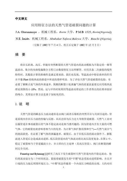
中文译文应用特征方法的天然气管道破裂问题的计算J.A. Olorunmaiye,机械工程系,Ilorin大学,P.M.B. 1525, Ilorin(Nigeria)) N.E. Imide,机械工程系,Abubakar Tafawa Balewa大学,Bauchi (Nigeria) (完稿于1992年7月4日,校正后定稿于1992年12月2日)摘要将在长距离、高压、伴随有突然断裂的天然气管道内的流动模拟为不稳定的一维等温流动。
集合的双曲线偏微分方程已由数值特征方法所解答。
应用具备二次插值的线性特性时,其数值计算的准确性是满足要求的。
我们也发现,等温流动中特征曲率的作用并不像Flatt的绝热流的报道中所说的那样明显。
为了评估天然气管道破裂的危险,有必要了解断点处气体的外泄速率。
预测的断裂口处泄漏气体的质量流量要比应用绝热流理论预算的小18%,然而,这与早些时候利用等温流动理论的工作者得出的结果却很好的吻合,其理论计算方法是基于加权残差的。
1.说明天然气管道的瞬态压力波动通常是由阀门或者压缩机的突然开启与关闭引起的。
管道系统内存在压力波的传输与反射,从而会因为压力过大导致管道破裂。
天然气工业对长输管道在事故破裂后的气体不稳定流动是相当感兴趣的,因为管道内含有大量的可燃气体,它的破裂也就意味着相当大的危害。
为计算气体扩散范围和空气—天然气混合气的地面浓度,有必要了解气体的泄漏速率。
破裂后,由于在低压段的流动条件下,膨胀波进入管道后会造成流动逆转,低压段管道内的气体流动将比高压段更复杂。
在图1中,假定了破裂相当于管道截面大小,并立即向左方延伸(其高压管段),阀门在断裂的瞬间完全关闭。
Fannelsp and Ryhming [1]研究了高压下发生破裂时天然气管道内的不稳定流动。
他们将流动划分为三个时间状态。
紧接着破裂发生的“早期”状态受波动进程影响,并且开口端的压力接近周围环境压力。
“中期”状态伴随着一个内部压力峰值的出现,大约对应于流动逆转速度为0的位置。
油气储运专业英语词表
expansion refrigeration 膨胀制冷 * external phase 外相 exhaust stack 排气烟囱 * extractor n. 提取器 * extraction n. 抽取,提炼 family of curves 曲线簇 * Fahrenheit 华氏度 * feed n. 原料 feedstock n. 原料 * feedstock conversion 原料转化率 * feedstock quality 原料性质 * feasibility n. 可行性 * field-processing method 现场处理法,现 场加工法 * filter n. 过滤器 * filter separation 过滤式分离器 finely ad. 微细的 fire-retardant wall 防火墙 * fixed-bed 固定床 flare n. 火焰,火炬 * flash n. 闪光,闪蒸 * flash separator 闪蒸分离器 * flash zone 闪蒸区 flexibility n. 灵活性 * flowing pressure 流动压力 * flow controller 流量控制器 * flow diagram 流程图 * flueபைடு நூலகம்n. 烟道 * fluid-bed 流化床 * fluid-jacket heater 水套加热炉 * fluid coking 流化焦化 * formation n. 地层,岩层;形成物 * freezing point 冰点,凝固点 fractional a. 分数的,分馏的 * fractional distillation 精镏,分馏 * fractionation n. 精镏,分镏 * fractionating deck 蒸馏板 fraction n. 分数 fracture n. 破裂,断裂 * free water 游离水,自由水 * free water knockout (FWKO) 游离水分离 器 * furnace n. 炉 * gage column 量液管,液位指示管
油气储运专业英语
储运专业英语一、英译汉单词翻译CH1.Oil and Gas Fields 油气田1.1An Inroduction to oil and gas productiong油气生产介绍1.1.1gas processging气体加工1.1.2oil processing原油加工1.1.3water processing水处理1.1.4sand treatment砂处理1.1.5auxiliary equipment辅助设备1.2Brief description of crude oil surface treatment原油地面处理简介1.2.1 separators分离器1.2.2 oil treating原油处理1.2.3 heater-treaters加热处理器1.2.4 free water knockouts(FWKOs)游离水脱除器1.2.5vertical treaters立式处理器1.2.6 stabilization and sweetening of crude oil原油的稳定和脱酸1.2.7 storage tanks储罐1.3Treating oil field emulsions油田乳状液的处理1.3.1 theory of emulsions乳状液理论1.3.2 the major reasons for dehydrating crude oil原油脱水的主要原因1.3.3 treating methods处理方法1.3.4 some common terms一些常用术语1.4Overview of gas-handling facilities气体处理设备概论1.5Trays and packing塔板和填料1.5.1trays塔板1.5.1.1 sieve trays筛板1.5.1.2 valve trays 阀板1.5.1.3 bubble cap trays泡罩塔板1.5.1.4 high capacity/high efficiency trays高处理量/高效塔板1.5.1.5 bubble cap trays vs. valve trays泡罩塔板与阀板的比较1.5.1.6 tray efficiency and tower height塔板效率和塔高1.5.2 packing填料1.5.2.1 random packing随机填料1.5.2.2 stripping service规整填料1.6Gas sweetening气体脱酸1.6.1 gas sweetening processes气体脱硫工艺1.6.2amine processes胺工艺1.6.3 physical solvent processes物理溶剂工艺1.6.4direct conversion of H2S to sulfur H2S直接转换为硫磺1.6.5 gas permeation气体渗透1.7Dehydration of natural gas天然气脱水1.7.1 hydrates水合物1.7.2 dehydratoin of natural gas天然气脱水1.7.2.1 dew-point depression露点降1.7.2.2 liquid-desiccant dehydrators液体干燥剂脱水器1.8Hydrocarbon recovery and condensate stabilization烃回收和凝液稳定1.8.1hydrocarbon recovery processes烃回收工艺1.8.2absorber and stripper units吸收塔和气提装置1.8.3 condensate stabilization凝液稳定CH2 Pipelines管道2.1 types of pipelines管道类型2.1.1 oil pipelines输油管道2.1.1.1 flowlines出油管2.1.1.2 gathering lines集油管道2.1.1.3crude trunk lines原油干线管道2.1.2 gas pipelines输气管道2.1.2.1gas gathering集气管道2.1.2.2gas transmission输气干线2.1.3 products pipelines成品油管道2.2 other pipelines其他管道2.2.1two-phase pipelines两相流管道2.2.2LNG pipelines液化天然气管道2.2.3 CO2 pipelines CO2管道2.2.4 coal slurry pipelines煤浆管道2.3 rheology流变学2.3.1 what is rheology? 什么是流变学?2.3.2 viscosity黏度2.3.3 non-newtonian liquids非牛顿流体2.3.4 high pour and high viscosity高倾点和高粘度2.4 line pipes管道用管2.4.1 specifications规范2.4.2 steel pipe钢管2.4.3 other types of pipe其他类型的管子2.5 pumps and pump stations泵和泵站2.5.1 investment distributions投资分配2.5.2 pump stations泵站2.5.2.1 the number of pump stations泵站数2.5.2.2 station equipment泵站设备2.5.3 pumps泵2.5.3.1 centrifugal pumps容积泵2.5.4 types of station operation泵站操作类型2.5.4.1 put and take operation罐到罐操作2.5.4.2 float tank operation旁接罐操作2.5.4.3 tight line operation密闭操作2.6 compressors压缩机2.6.1 reciprocating compressors往复式压缩机2.6.2 centrifugal compressors离心压缩机2.6.3 compression ratio压缩比2.6.4 capacity and horsepower流量和功率2.6.5 other considerations其他考虑因素2.7 gas turbines燃气透平2.7.1 types of gas turbines燃气透平类型2.7.2 operation操作2.8 pipeline pigging管道清管2.8.1 pigging 清管2.8.2 example of pigging operatings清管操作的例子2.8.3 launching and receiving发送和接收2.9 pipe coating管子覆盖层2.9.1 exterior corrosion coating外防腐覆盖层2.9.2 concrete coating混凝土加重层2.10 inspection and rehabilitation检查和修复2.10.1 inspecion检查2.10.2 in-line tools管内检查器2.10.3 rehabilitation修复2.10.3.1 external corrosion外腐蚀2.10.3.2 trans alaska pipeline repair横贯阿拉斯加管道的修理CH3 storage facilities储存设施3.1 storage储存3.1.1 crude storage原油储存3.1.2 natural gas liquids天然气凝析油3.1.3 natural gas天然气储存3.1.4LNG 液化天然气3.2 tand classification罐的分类3.2.1 tank classification储罐分类3.2.1.1 atmospheric tanks常压罐3.2.1.2 low-pressure tanks低压罐3.2.1.3 pressure vessels (high-pressure tanks)压力容器(高压罐)3.2.2 major tank components储罐主要部件3.2.2.1 fixed-foof tanks固定顶储罐3.2.2.2 floating-roof tanks浮顶罐3.2.2.3 tank bottoms罐底3.3 floating roofs浮顶3.3.1 external floating roofs外浮顶3.3.1.1 roof types顶的类型3.3.1.2 support legs支柱3.3.1.3 vents通风3.3.1.4 drainage排水3.3.1.5 wind girders抗风圈3.3.2 internal floating roofs内浮顶3.3.2.1 steel roofs钢顶3.3.2.2 aluminum roofs铝顶3.4 rim seals边缘密封3.4.1 external floating-roof seals外浮顶密封3.4.1.1 mechanical shoe seals机械滑板密封3.4.1.2 resilint toroid seals弹性环密封3.4.1.3 flexible wiper seals柔性刷密封3.4.1.4 weather shield风雨罩3.4.2 internal floating-roof seals内浮顶密封3.5 tank emissions and venting储罐发散物和通风3.5.1 mechanisms of evaporation losses蒸发损耗机理3.5.1.1 fixed-roof tanks固定顶储罐3.5.2 tank type and emissions储罐类型和发散3.5.2.1 fixed-roof tanks固定顶罐3.5.2.2 external floating-roof tanks外浮顶罐3.5.2.3 internal floating-roof tanks内浮顶罐3.5.3PV valves压力真空阀3.5.3.1 general概要3.5.3.2 how the PV valve works PV阀的工作3.5.4 emergency venting 应急泄压3.6 tank foundations储罐基础3.6.1 introduction to tank foundations储罐基础介绍3.6.1.1 preliminary studies初步研究3.6.1.2 soil investigations土壤研究3.6.2 imprtant elements to consider in foundation design基础设计中考虑的重要因素3.6.2.1 foundation elevation基础标高3.6.2.2 drainage排水3.6.2.3 oil sand under tank bottom罐底下的油砂3.6.3 tank foundation types储罐基础类型3.6.3.1 concrete ringwall foundations混凝土圈座基础3.6.3.2 crushed-srone ringwall foundations碎石圈座基础3.6.3.3compacted soil foundations夯土基础3.6.3.4 slab foundations平板基础3.6.3.5 pile-supported foundations桩柱支撑基础3.7 fire prevention and foam system防火和泡沫系统3.7.1 foam fire fighting systems泡沫灭火系统3.7.1.1 fluidity流动性3.7.1.2 expansion膨胀性3.7.1.3drainage rate吸水率3.7.2 foam making devices泡沫发生装置3.8 oil storage in rock caverns在岩洞内储存石油3.8.1 storage at 1 atmosphere在大气压下储存3.8.2 cavern design and constrution岩洞设计及建造3.8.3 general operation and maintenance操作和维护3.8.3.1 pumps泵3.8.3.2 heating加热3.8.3.3 sludge 沉积物3.8.3.4 level control and volume measurement液位控制和体积测量3.8.4 advantages of rock cavern storage岩洞储存的优点CH4 construcion建设4.1 land pipeline construction陆上管道建设4.1.1 construction classification建设分类4.1.2 land pipeline construction陆上管道建设4.2 pipeline installation and road/river crossing管道安装和管道/河流穿越4.2.1 installaton安装4.2.2 road/river crossings道路/河流的穿越4.2.3 testing试压4.2.4 drying and cleaning干燥和清管4.2.5 station construction站的建设4.3 offshore pipeline construction海洋管道建设4.3.1 conventional lay barge常规铺管船4.3.2 reel barge卷筒船4.3.3 vertical pipelaying垂直铺管4.4 pull methods and tie-in牵引法和碰固定口连接4.4.1 pull methods牵引法4.4.2 tie-in碰固定口连接4.5 welding techniques and equipment焊接技术和设备4.5.1 welding processes焊接工艺4.5.2 welding procedures and equipment焊接程序及设备4.5.2.1 weld passes焊道4.5.2.2 manual welding手工焊接4.5.2.3 automatic welding自动焊4.5.2.4 preparation for welding焊接准备4.5.2.5 inspection and testing检查与试验4.5.2.6 weld defects焊接缺陷4.5.3 other joining methods其他连接方法CH5 corrosion腐蚀5.1 cause of underground corrosion地下腐蚀的原因5.1.1 electrolytic corrosion电解腐蚀5.1.2 galvanic corrosion电池腐蚀5.1.2.1 dissimilar metals不同金属5.1.2.2 dissimilar environments不同环境5.2 cathodic protection fundamentals阴极保护的基本原理5.2.1 corrosion and corrosion control腐蚀和服饰控制5.2.1.1 electrically insulating anode area from cathodic area阳极区和阴极区的电绝缘5.2.1.2 electrically insulating anode or cathode from the elecrolyte阳极或阴极与电解质的电绝缘5.2.1.3 treatment of electrolyte电解质处理5.2.1.4 use of nonmetallic materials非金属材料的应用5.2.2 cathodic protection阴极保护5.2.2.1 galvanic cathodic protection systems原电池阴极保护系统5.2.2.2 impressed current systems外加电流系统5.2.3 design and criteria for cathodic protection阴极保护的设计和准则5.3 pipeline corrosion管道腐蚀5.3.1 estimating the corrosion risk腐蚀风险评估5.3.1.1 intrinsic corrosiveness of the soil土壤固有的腐蚀性5.3.1.2 electrolytic effects电解作用5.3.2 corrosion protection腐蚀防护5.3.2.1 insulating coatings绝缘涂层5.3.2.2 cathodic protection阴极保护5.3.2.3 protection against electrolysis电解的保护5.4 tank corrosion储罐腐蚀5.4.1 descriptive nature of tank corrosion储罐腐蚀性质描述5.4.1.1 atmospheric corrosion大气腐蚀5.4.1.2 product side corrosion油品接触面腐蚀5.4.1.3 bottom corrosion罐底腐蚀5.4.1.4 vapor space corrosion蒸气空间腐蚀5.4.1.5 interface corrosion界面腐蚀5.4.1.6 bottom underside corrosion罐底下侧腐蚀5.4.2 corrosion control and prevention腐蚀控制及防护5.4.3 specific storage tank corrosion service problems专用储罐的腐蚀问题(石油产品)5.4.3.1 crude oil tanks原油储罐5.4.3.2 refined hydrocarbon storage tanks成品油储罐5.4.4 corrosion prevention with linings用涂层防腐5.4.4.1 basic types of lining涂层的基本类型5.4.4.2 surface preparation表面预处理5.4.4.3 precleaning预清洗5.4.4.4 abrasive blasting喷磨处理5.4.4.5 other surface preparation methods其他表面预处理方法5.4.5 corrosion prevention with cathodic protection用阴极保护防止腐蚀5.4.5.1 cathodic protection阴极保护5.4.5.2 polarization极化5.4.5.3 electrical potential measurement电位测量5.4.5.4 current requirements电流需求5.4.5.5 internal versus external cathodic protection内部与外部阴极保护CH6 metering installations计量装置6.1 metering gases气体计量6.1.1differential pressure meters差压流量计6.1.2 positive-displacement meters(PD)容积式流量计(PD)6.1.3 turbine-type meters涡轮流量计6.1.4 mass-flow meters质量流量计6.2metering of liquids液体计量6.2.1 types of meters in use在用流量计类型6.2.2 positive-displacement meters容积式流量计6.2.3 turbine meters涡轮流量计6.2.4 meter calibration流量计标定6.3 BTU measurement热值测量欢迎您的下载,资料仅供参考!致力为企业和个人提供合同协议,策划案计划书,学习资料等等打造全网一站式需求。
专业英语课程论文-油气储运工程TechnicalEnglishforOilandGas

T echnical English for Oil and GasStorage and T ransportation Engineering Since September this year, we have had a new course called Technical English for oil and gas storage and transportation engineering. Professor Liu is the teacher of this course and she is very well to us. In the teaching of Professor Liu, I get much knowledge and I fell very happy.Now,let me write somethings about my profession with some personnal ideals.Extensive Reading①The title of the first paper I viewed is “Fluid and Hydraulic System”.As far as I am concerned,this paper mainly describes two important contents which are fluid and hydraulic system.The former part of this paper gives an account of Fluid that is a substance which may flow.Its constituent particles may continuously change their positions relative to one another.Moreover,it offers no lasting resistance to the displacement,however great ,of one layer over another.This means that,if the fluid is at rest,no shear force(that is a force tangential to the surface on which it acts)can exist in it.Meanwhile,fluid may be classified as Newtonian or non- Newtonian.In Newtonian fluid there is a linear relation between the magnitude of applied shear stresses and the resulting rate of angulardeformation.In non- Newtonian fluid there is a nonlinear relation between the magnitude of applied shear stresses and the resulting rate of angular deformation.The after part of this paper is concerned with the hydraulic system. I think the ligament between the two sides is “Pascal’s law”. Because all hydraulic systems depend on Pascal’s law,named after Braise Pascal, who discovered the law. This law states that pressurized fluid within a closed container-such as cylinder or pipe-exerts equal force on all of the surfaces of the container. Moreover, in actual hydraulic systems, Pascal’s law defines the basis of the results which are obtained from the system.Thus,pump moves the liquid in the system. The intake of the pump is connected to a liquid source,usually called the tank or reservoir. Atmospheric pressure,pressing on the liquid in the reservior,forces the liquid into the pump.when the pump operates,it forces liquid from the tank into the discharge pipe at a suitable pressure.②The title of the second paper I viewed is “A Discussion on Modern Design Optimization”. In this paper,the author focuses on the theory underlying some of the mathematical methods employed by design optimization procedures.To begin with, this paper treats of the optimization techniques taking one with another. The integration of optimization techniqueshas the power to reduce design costs by shifting the burden from the engineer to the computer. Furthermore,the mathematical rigor of a properly implemented potimization tool can add confidence to the design process.Modern optimization methods perform shape optimizations on components generated within a choice of CAD packages. Ideally, there is seamless data exchange via direct memory transfer between the CAD and FEA applications without the need for file translation. Furthermore, if associativity between the CAD and FEA software exist, any changes made in the CAD geometry are immediately reflected in the FEA model.The second, this paper describe how the optimization problem arises. Consider a three-step process:(1)Generation of geometry of part or assembly in CAD;(2)Creation of FEA mode of part or assembly;(3)Evaluation of results of FEA models.Meanwhile,most optimization problems are made up of three basic components.(1) An objective function which we want to minimize (or maximize). For instance, in designing an automobile panel, we might want to minimize the stress in a particular region.(2) A set of design variables that affect the value of theobjective function. In the automobile panel design problem, the variables used define the geometry and material of the panel.(3) A set of constraints that allow the design variables to have values but exclude others. In the automobile panel design problem, we would probably want limit its weight.The last but not the least, there is no beauideal in the world. Modern design optimization has many benefits and drawbacks. The elimination or reduction of repetitive manual tasks has been the impetus behind many software applications. Automatic design optimization is one of the latest applications used to reduce man-hours at the expense of possibly increasing the computational effort. It is even possible that an automatic design optimization scheme may actually require less computational effort than a manual approach. This is because the mathematical rigor on which these schemes are based may be more efficient than a human-based solution. Of course, these schemes do not replace human intuition, which can occasionally significantly shorten the design cycle. That is, no variable combination of the design parameters is left unconsidered. Thus,designs obtained using design optimization software should be accurate to within the resolution of the overall method.Intensive ReadingOriginal textIndustrial RobotA robot is an automatically controlled, reprogrammable, multipurpose, manipulating machine with several reprogrammable axes, which may be either fixed in place or mobile for use in industrial automation applications.The key words are reprogrammable and multipurpose because most single-purpose machines do not meet these two requirements. The term “multipurpose”means that the robot can perform many different functions, depending on the program and tooling cureently in use.Over the past two decades, the robot has been introduced into industry to perform many monotonous and often unsafe operations. Because robot can perform certain basic tasks more quickly and accurately than humans, they are being increasingly used in various manufacturing industries.The typical structure of industrial robot consists of 4 major components: the manipulator, the end effector, the power supply and the control system.The manipulator is a mechanical unit that provide motions similar to those of a human arm. It often has a shoulder joint, an elbow and a wrist. It can rotate or slide, stretch out and withdraw inevery possible direction with certain flexibility.The basic mechanical configurations of the robot manipulator are categorized as cartesian, cylindrical, spherical and ariculated. A robot with a cartesian geometry can move its gripper to any position within the cube or rectangle defined as its working volume. Cylindrical coordinate robots can move the gripper within a volume that is described by a cylinder. The cylindrical coordinate robot is positioned in the work area by two linear movements in the X and Y directions and one angular rotation about the axis. Spherical arm geometry robots position the wrist through two rotation and one linear actuation. Articulated industrial robots have an irregular work envelope. This type of robot has two main variants,vertically articulated and horizontally articulated.The end effector attaches itself to the end of robot wrist, also called end-of-arm tooling. It is the device intended for performing the designed operations as a human as a human hand can. End effectors are generally custom-made to meet special handling requirements. Mechanical grippers are the most commonly used and are equipped with two or more fingers. The selection of an appropriate end effector for a specific application depends on such factors as the payload, environment, reliability, and cost.The power supply is the actuator for moving the robot arm,controlling the joints and operating the end effector. The basic types of power sources include electrical, pneumatic, and hydraulic. Each source of energy and each type of motor has its own characteristics, advantages and limitations. An ac-powered or dc-powered motor may be used depending on the systerm design and applications. These motors convert electrical energy into mechanical energy to power the robot. Most new robot use electrical power supply. Pneumatic actuators have been used for high speed, nonservo robots and are often used for powering tooling such as grippers. Hydraulic actuators have been used for heavier lift system, typically where accuracy was not also required.The control system is the communications and information-processing system that gives commands for the movements of the robot. It is the brain of the robot; it sends signals to the power source to move the robot arm to a specific position and to actuate the end effector. It is also the nerves of the robot ; it is reprogrammable to send out sequences of instructions for all movements and actions to be taken by the robot.An open-loop controller is the simplest form of the control system, which controls the robot only by following the predetermined step-by-step instructions. This system does not have a self-correcting capability. A close-loop control system uses feedbacksensors to produce signals that felect the current states of the controlled objects. By comparing those feedback signals with the values set by the programmer, the close-loop controller can conduct the robot to move to the precise position and assume the desired attitude, and the end effector can perform with very high accuracy as the close-loop control system can minimize the discrepancy between the controlled object and the predetermined references.Industrial robots vary widely in size, shape, number of axes, degrees of freedom, and design configuration. Each factor influences the dimensions of the robot’s working envelope or the volume of space within which it can move and perform its designated task. A broader classification of robots can been described as below.Fixed-and V ariable-Sequence Robots. The fixed-sequence robot(also called a pick-and place robot) is programmed for a specific sequence of operation. Its movements are from point to point, and the cycle is repeated continuously. The variable-sequence robot can be programmed for a specific sequence of operations but can be reprogrammed to perform another sequence of operation.Playback Robot. An operator leads or walks the playback robot and its end effector through the desired path. The robot memorizes and records the path and sequence of motions and can repeat them continually without any further action or guidance by the operator.Numerically Controlled Robot. The numerically controlled robot is programmed and operated much like a numerically controlled machine. The robot is servo-controlled by digital data, and its sequence of movements can be changed with relative ease.Intelligent Robot. The intelligent robot is capable of performing some of the functions and tasks carried out by human beings. It is equipped with a variety of sensors with visual and tactile capabilities.The robot is a very special type of production tool; as a result, the applications in which robots are used are quite broad. These applications can be grouped into three categories: material processing, material handing and assembly.In material processing, robot use tools to process the raw material. For example, the robot tools could include a drill and the robot would be able to perform drilling operations on raw material.Material handing consists of the loading, unloading, and transferring of workpieces in manufacturing facilities. These operations can be performed reliably and repeatedly with robots, thereby improving quality and reducing scrap losses.Assembly is another large application area for using robotics. An automatic assembly system can incorporate automatic testing, robot automation and mechanical handing for reducing labor costs,increaing output and eliminating manual handing concerns.What I have learned form the upper paper is listed as followNowadays, along with the fast pace of economic development, more and more Industrial robots have been presented in our living. Industrial robots have many merits and their applications are very abroad in the world.The former three paragraphs of the paper mainly introduce the short and the long of the industrial robots. W e generally realize the functions and use of them. W e know that robots have been used in various vocations. There is a word “reprogrammable”that attracts me in the second paragraph. In my opinion, the term “reprogrammable” implies two things: The robot operates according to a written program, and this program can be written to accommodate a variety of manufacturing tasks.From 4th to 10th paragraph, this paper mainly introduce the structures of robots. There are a large number of professional words which I list as follow.Elbo(肘) wrist(腕) shoulder joint(肩关节) Coordinate(坐标) volume(范围) cylindrical(圆柱的) spherical(球状的) open-loop(开环) close-loop(闭环) articulated(铰接的) cartesian(笛卡尔的) pneumatic(气动的) payload(有效载荷) feedback(反馈) nonservo(非伺服系统) end effector(终端操作机构)When I read the first sentence of the 4th paragraph, I wonde what is the mechanical unit. V ia some reference books, I know that the major of mechanism is the mechanical system. And the mechanical system is decomposed into mechanisms,which can be further decomposed ino mechanical components. In this sense, the mechanical components are the fundamental elements of machinery. On the whole, mechanical components Can be classified as universal and special components.From 11th to 15th paragraph, this paper mainly introduce the classification of robots. In the point, the classification is presented broad sense. as a matter of fact, there are a lot of categorys of the classification. What attracts me is the word “playback”. The original intention of “playback”is “repeatedly play”, but over here, it’s meaning is “示教”.The last four paragraphs mainly introduce several robot applications. At present there are two main types of robots, based on their use: general-purpose autonomous robots(通用机器人)and dedicated robots(专用机器人). Robots can be classified by their specificity of purpose. There are many application in our society nowadays. For example, in our school, they has three main applications: Robotic kits, V irtual tutors and teacher's assistants.Along with various techniques having emerged to develop the science of robotics and robots, One method shows itself that is evolutionary robotics, in which a number of differing robots are submitted to tests. Those which perform best are used as a model to create a subsequent "generation" of robots. Another method is developmental robotics, which tracks changes and development within a single in the areas of problem-solving and other functions.In a word, the prospect of robots is very bright.Appendix: all the papers in my discourse are extracted from the book named Technical English published in Peking University Press that borrowed from the library of my school.。
储运专业英语部分单词和短语
储运专业英语部分单词和短语储运专业英语2.5 Pumps and Pump Stations1a range of ...的范围acquisition n.获取,采集alignment n.校正,调中,对中batch n.一次投放量,批料be in phase 相同的,协调的be selected from 从。
挑选出来bracing n.支撑,拉杆bypase n./vt.旁通;设旁通calibrate vt.校正,标定commingle v.混合,参和concentric with 与。
同心crankshaft n.曲轴criteria n.标准,准则horsepower n.马力,功率isolate n./v切断,隔离miscellaneous a.混杂的overlap v.相互重叠pig n.清管器prolong vt.延长rating n.额定值,定额;等级scraper n.刮管器,清管器sharply ad.锐利地,严格地shutdown n.停运,关机smooth out 消除,使平滑sophistication n.复杂(化),完善split v.分裂,剖分stroke n.冲程sump n.水池tankage n.储罐容量,容器设备total-总容量tender n.管输中的一批油品undue a.过度的,非常的vibration n.震动waterflooding n.注水开发2atmospheric pressure 大气压booster atation 增压站capacity rating 额定生产率date acquisition system 数据采集系统discharge pressure 排出压力drilling mud 钻井泥浆drilling rig 钻机duplex pump 双缸泵electric motor 电动机end-suction pump 端面吸入泵environmental pretection 环境保护evaporation losses 蒸发损失float tank operation 旁接罐操作head-capacity curve 扬程-流量曲线initial station 首站,始发站inline pump 管道泵intermediate station 中间站interstate pipeline 州际管道meter prover 流量计标定装置miscellaneous costs 杂费net positive suction head 汽蚀余量,泵入口处的绝对压力oil recovery 原油回收originating station 首站,始发站pressurized tank 压力罐prime mover 原动机put and take operation 罐到罐操作rating curves 额定曲线,特性曲线reciprocating pump 往复泵scraper trap 刮管器收发桶,清管器收发筒shaft horsepower 轴功率side-suction pump 侧面吸入泵smart pig 智能清管器spare pump 备用泵specific speed 比转速station site 站址suction booster pump 吸入增压泵suction pressure 吸入压力tight line operation 密闭操作triplex pump 三缸泵vapor lock 气锁2.6 Compressors1balance n./v平衡bank n.一排,管束be designed to 设计成能。
油气储运专业英语reading部分翻译

油气储运专业英语reading部分翻译Petroleum and Its Modern Uses[1] Petroleum, coal, and natural gas are the most widely used sources of energy in the m odern world. They are of primary importance in the industrialized countries, where vast am ounts of energy are consumed to operate the different kinds of machines used today. The se three energy sources are collectively referred to as fossil fuels.石油、煤炭和天然气是现代世界最广泛使用的能源。
它们在工业化国家中最为重要,在这些国家,人们消耗大量的能源来操作今天使用的各种机器。
这三种能源统称为化石燃料。
[2] At various depths beneath land and sea, there are accumulations of hydrocarbons form ed millions and even hundreds of millions of years ago by decomposition of animal and v egetable remains. They were covered by sand or mud, which in time was itself covered by the water of the seas. Hydrocarbons are compounds of hydrogen and carbon which, at n ormal temperatures and pressures, may be gaseous, liquid or solid according to their mole cular complexity. The natural deposits are correspondingly gaseous, liquid or solid, dependi ng on the relative proportion of the various hydrocarbons present in mixture. Petroleum is composed largely of the remains of these tiny marine animals and plants that lived so lo ng ago.在陆地和海洋的不同深处,有数百万年甚至数亿年前由于动物和植物残骸的分解而形成的碳氢化合物的积聚。
油气储运英语
tank
fixed-roof tanks 固定顶储罐 PV valves(pressure vacuum vent valves) 压力真空阀 external floating roof tanks(EFR tanks) 外浮顶罐 internal floating roof tanks(IFR tanks) 内浮顶罐 pontoon[pɑ:nˈtu:n]浮舱 rim seals 边缘密封 mechanical shoe seals 机械滑板密封 resilient [rɪˈz ɪliənt] toroid ['tɔ:rɔɪd] seals 弹性环密封
Useful Words and Phrases in major Oil-gas Storage and Transportation
By:ZhouHeng
emulsion
emulsion[ɪˈm ʌlʃən] 乳状液 immiscible[ɪˈm ɪsəbl] 非互溶的 dispersed/continuous phase 分散相/连续相 oil-in-water emulsions 水包油乳状液 water-in-oil emulsioins 油包水乳状液 phase inversion 相反转 demulsifier 破乳剂 coalescence[ˈk əʊə‘lesns] 聚结
sweetening and dehydration
sulfur compound 硫化物 amine processes 胺工艺 physical solvent processes 物理溶剂工艺 diethanolamine(DEA) dew point 露点 affinity 亲和力 liquid-desiccant dehydrators 液体干燥剂脱水器 solid-desiccant dehydrators 固体干燥剂脱水器
油气储运专业英语[汇总]
![油气储运专业英语[汇总]](https://img.taocdn.com/s3/m/ba934255326c1eb91a37f111f18583d049640fa9.png)
FPSO:Floating Production, Storage and Offloading. Typically a tanker type hull or barge with wellheads on a turret that the ship can rotate freely around (to point into wind, waves or current). The turret has wire rope and chain connections to several anchors (position mooring-POSMOR), or it can be dynamically positioned using thrusters (dynamic positioning-DYNPOS). Water depths 200 to 200 meters, Common with subsea wells. The main process is placed on the deck, while the hull is used for storage and offloading to a shuttle tanker. May also be used with pipeline transport.TLP: A Tension Leg Platform consists of a structure held in place by vertical tendons connected to the sea floor by pile-secured templates. The structure is held in a fixed position by tensioned tendons, which provide for use of the TLP in a broad water depth rang up to about 2000m. Limited vertical motion. The tendons are constructed as hollow high tensile strength steel pipes that carry the spare buoyancy of the structure and ensure limited vertical motion. A variant is Seastar platforms which are miniature floating tension leg platforms, much like the semi submersible type, with tensioned tendons.SPAR: The SPAR consists of a single tall floating cylinder hull, supporting a fixed deck. The cylinder however does not extend all the way to the seafloor, but instead is tethered to the bottom by a series of cables and lines. The large cylinder serves to stabilize the platform in the water, and allows for movement to absorb the force of potential hurricanes. Spars can be quite large and are used for water depths from 300 and up to 3000 meters. SPAR is not an acronym, but refers to its likeness with a ship’s spar. Spars can support dry completion wells, but is more often used with subsea wells.To get the last of the water out of the oil, the oil is processed through an oil treater or a treating system. A treater is similar to a separator, but with special features to help separate the water from the oil. Treaters or treating systems usually provide heat to reduce oil viscosity and large settling sections to allow the water time to settle from the oil, and may provide an electrostatic grid to promote coalescing of the water droplets. Conventional treaters usually have a front section with a heater in which the emulsion is heated and initial separation of the “free water” takes place. The oil then flows to a second section of the vessel, where additional coalescence and settling of the water droplets takes place. Gas is flashed (i.e. liberated) from the emulsion as the pressure is lowered and the temperature is raised from the upstream separator. For a conventional treater with a heater, free-water knockout section, and settling section, the water content in the oil can be reduced to less than 1%. An electrostatic treater, which is a conventional treater with anelectrostatic grid in the settling section, can reduce the water content to 0.3 to 0.5%by vol ume.The rotating part of the compressor consists of all the impellers. It runs on two radial bearings (on all modern compressors, there are hydrodynamic tilt pad bearings), while the axial thrust generated by the impellers is balanced by a balance piston, and resulting force is balanced by a hydrodynamic tilt pad thrust bearing. To keep the gas from escaping at the shaft ends, dry gas seals are used. The entire assembly is contained i n a casi ng (usual l y barrel type).The different working principles cause differences in the operating characteristics of the centrifugal compressors compared to those the reciprocating unit. Centrifugal compressors are used in a wide variety of applications in chemical plants, refineries, onshore and offshore gas lift and gas injection application, gas gathering, and in the transmission of natural gas. Centrifugal compressors can be used for outlet pressures as high as 10000 psia,thus overlapping with reciprocating compressors over a portion of the flow rate/pressure domain. Centrifugal compressors are usually either turbine or electric motor driven. Typical operating speeds for centrifugal compressors in gas transmission applications are about 14000 rpm for 5000-hp units 8000 rpm for 20000-hp units.The task of gas compression is to bring gas from a certain suction pressure to a higher discharge pressure by means of mechanical work. The actual compression process is often compared to one of three ideal processes: isothermal, isentropic, and polytrophic compression.Mercaptans are compounds that occur naturally in sour gas. They are hydrocarbon compounds that have a sulfur atom inserted between a carbon atom and a hydrogen atom. Methyl, ethyl, propyl, and butyl merchantman are some examples. Mercaptans have a strong offensive odor, and certain mixtures of manufactured mercaptan, such as tertiary butyl mercaptan and isopropy mercaptan, as well as others, are added to sweet natural gas to odorize the gas prior to domestic or commercial consumption.Most of the regenerative chemical sweetening solvents are alkanolamines, which are compounds formed by replacing one, two, or three hydrogen atoms of the ammonia molecule with radicals of other compounds to form primary, secondary, or tertiary amines respectively. Amines are weak organic bases that have been used for many years in gas treating to remove CO2 and H2S fromnatural gas as well as from synthesis gas. These compounds combine chemically with the acid gases in the contactor to form unstable salts. The salts break down under the elevated temperature and low pressure in the still.The flow to and from reciprocating compressors is subject to significant pressure fluctuations due to the reciprocating compression process. Therefore, pulsation dampeners have to be installed upstream and downstream of the compressor to avoid damages to other equipment. The pressure losses (several percent of the static flow pressure) of these dampeners have to be accounted for in the station design.Reciprocating compressors are widely utilized in the gas processing industries because they are flexible in throughput and discharge pressure range. Reciprocating compressors are classified as either “high speed” or “slow speed”. Typically, high-speed compressors operate at speeds of 900 to 1200 rpm and slow-speed units at speeds of 200 to 600 rpm. High-speed units are normally “separable”i.e., the compressor frame and driver are separated by a coupling or gearbox. For an “integral”unit, power cylinders are mounted on the frame as compressor cylinders, and power pistons ate attached to the same drive shaft as the compressor cylinders. Low-speed units are typically integral in design.Isothermal compression occurs when the temperature is kept constant during the compression process. It is not adiabatic because the heat generated in the compression process has to be removed from the system.The compression process is isentropic or adiabatic reversible if no heat is added to or removed from the gas during compression and process is frictionless. With these assumptions, the entropy of the gas does not change during the compression process.Diglycolamine (DGA). The DGA process was developed by The Fluor Crop. in the 1950s, which called the process the Econamine Process. The advantage of DGA over MEA appears to be the lower solution rate owing to the higher solvent concentration, resulting in higher acid gas pickup per volume of solution circulated. This yields capital saving, as the regeneration equipment is smaller for DGA than for MEA. Disadvantage appear to be degradation of the chemical with CO2 and greater solubility of heavier hydrocarbons in the solution, as compared to MEA. This is a serious drawback if the acid gas steam is fed to a Claus plant, as additional air is required for the combustion of the hydrocarbons. Also, this dilutes the sulfur compounds in the sulfur recoverytrain. Solution strength is on the order of 50 to 70% by weight of DGA in water, which mol loadings in the range of 0.3 to 0.4 moles of acid gas per mole of DGA circulated. The DGA process train usually includes a reclaimer Diglycolamine(DGA的)。
油气储运专业英语词汇
油气储运专业英语词汇油品储运系统常用工作用词序号中文英文1润滑油lubrication2盘车pump rotation3过滤器filter4均匀混合器mixer5疏水器water trap6抗磨剂anti-wear agent7抗氧剂anti-oxidant agent8抗静电剂anti-static agent9安全阀safety valve10旁路by-pass11法兰flange12垫片gasket13螺栓bolt14螺母nut15螺丝刀screw driver16阀扳手wrench17灭火器extinguisher18下水井sewage well19报警仪alarm annunciator20对讲机walking talking21安全帽safety helmet22工作服uniform23手套glove24泄漏leakage25堵塞block26损坏damage27汽油gasoline28航煤jet fuel29柴油diesel30液化气LPG( liquefied petroleum gas ) 31燃料油fuel oil 32液碱liquid alkaline33废水waste water34蒸汽steam35氨水ammonia36硫化氢sulfureted hydrogen37胶皮管rubber hose38开关switch39灯lamp40冷却水cooling water41换热器heat exchanger42罐tank43机械密封mechanical seal44油杯oil cup45轴承bearing46轴承箱bearing case47抹布towel48拖布mop49铁锹spade50压力表pressure gauge51流量表flow meter52调节阀control valve53手电筒flashlight54油尺dipping meter55电机motor56油壶oil kettle57油桶oil barrel58库房warehouse59修理repair60正常normal61浮盘float roof62吹扫purge63分液罐dewatering drum64工艺流程flow path65盲板block plate66突沸sudden boiling67串岗off post68空气呼吸器air breather69密度density70馏程distillation71真空度vacuum72盘根packing73润滑脂grease74碱渣caustic sludge75补偿器compensator76循环circulation77防护罩safety case78组份cut79样品sample80分析单analysing sheet81化验室laboratory82调度dispatch83闪点flash point84蒸汽压vapor pressure85合格证certification86辛烷值octane number87离心泵centrifugal pump 88螺杆泵screw pump89静电static electricity 90通风ventilation 91摩擦friction92搅拌churn up93火炬flare94水封罐water seal tank95溢流over flow96避雷器lightning arrester97呼吸阀respiratory valve98透光孔light hole99附件adjunct100阻火器flame arrester101加热盘管heat coil102伴热线heat trace103罐容capacity104试水膏water paste105防爆工具explosive proof tools。
对油气储运认识作文英语
对油气储运认识作文英语标题,Understanding of Oil and Gas Storage and Transportation。
Oil and gas storage and transportation play a vitalrole in the global energy landscape, serving as thearteries that connect production centers with consumers around the world. In this essay, we will delve into the significance, challenges, and future prospects of oil and gas storage and transportation.Firstly, let's explore the importance of oil and gas storage and transportation. Oil and gas are among the most valuable and widely used resources on the planet, powering industries, transportation, and households. Efficient storage and transportation ensure a steady supply of these resources to meet the demands of various sectors. Pipelines, tankers, and storage facilities form the backbone of this infrastructure, enabling the seamless flow of oil and gas from extraction sites to refineries and ultimately to end-users.However, the industry faces numerous challenges. One of the primary concerns is safety. The transportation of oil and gas, whether through pipelines or tankers, carries inherent risks of spills, leaks, and accidents, which can have devastating environmental and economic consequences. Therefore, stringent safety regulations and technological advancements are crucial to mitigating these risks and ensuring the protection of both the environment and human lives.Another challenge is the need for continuous innovation and investment in infrastructure. As global energy demands evolve and new extraction technologies emerge, the existing storage and transportation networks must adapt to accommodate these changes. This requires significantcapital investment and collaboration between governments, industry players, and other stakeholders to modernize and expand infrastructure capacity.Moreover, geopolitical factors often influence oil andgas storage and transportation. Conflicts in oil-rich regions, trade disputes, and shifting alliances can disrupt supply chains and lead to fluctuations in prices. Therefore, diversification of supply sources and the development of alternative energy sources are essential strategies to enhance energy security and reduce reliance ongeopolitically sensitive regions.Looking ahead, the future of oil and gas storage and transportation is influenced by several trends. The growing emphasis on sustainability and environmental responsibility is driving the adoption of cleaner technologies andpractices across the industry. This includes investments in renewable energy sources, such as solar and wind, as wellas advancements in carbon capture and storage (CCS) technologies to reduce greenhouse gas emissions from fossil fuel operations.Furthermore, digitalization and automation are transforming the way oil and gas are stored and transported. Smart sensors, data analytics, and artificial intelligence are being deployed to optimize operations, enhance safety,and minimize downtime. This digital transformation not only improves efficiency but also enables proactive maintenance and real-time monitoring of infrastructure assets.In conclusion, oil and gas storage and transportation are indispensable components of the global energy system, supporting economic development and improving living standards worldwide. Despite facing various challenges, including safety risks, infrastructure limitations, and geopolitical uncertainties, the industry is adapting to meet the evolving demands of the 21st century. By embracing innovation, sustainability, and collaboration, stakeholders can ensure a reliable and sustainable energy future for generations to come.This essay offers an overview of the importance, challenges, and future prospects of oil and gas storage and transportation, highlighting the need for innovation, safety, and sustainability in the industry.。
化学工程 油气运输 外文翻译 外文文献 英文文献
毕业设计(论文)外文翻译毕业设计(论文)题目:关于加油站及油罐车的油气回收外文翻译(一)题目:Mechanical Degradation and Changes in Conformation ofHydrophobically Modified StarchOSA改性淀粉的机械降解和结构变化外文翻译(二)题目:Preparation and Properties of Octenyl Succinic AnhydrideModified Early Indica Rice Starch辛烯基丁二酸酐(OSA)改性早籼淀粉的制备和性能低成本和高可靠的喷射压缩机采用油气回收领域,以解决生态问题,在开发节能技术。
一定的技术困难,但是,这个操作复杂设备在最佳条件下,即:有效的参数范围狭窄喷气熟悉设计压缩机遇到喷射压缩机启动和稳定运行的复杂性液体收益访问接收室。
血压波动也使自己感到液体喷射压缩机的运作产生负面影响。
在同时,压力和流量的变化是恢复,积累就业的运作系统的特点,石油和天然气的加工。
在这方面,要研究液体喷射压缩机的操作下变条件,包括该设备的监管。
OAO跟Orenburgneft “液体喷射压缩机的设计,开发与双流量喷嘴集结合可调驱动电源泵,使人们有可能以不同的尺寸和无量纲特征喷射装置。
液体喷射压缩机的实验研究进行了在一条长凳上安装的IM Gubkin俄罗斯石油和天然气的州立大学。
在这些调查过程中,添置介绍了液体喷射压缩机相似理论[1]。
喷射压缩机的基本组件如下:- 直接流喷嘴组,以确保工作液喷射形成与调节的可能性射流压缩部分,科里奥利和Boussienesq系数的直径;- 一个环形接收室的入口和出口之间的部分,以确保交付的介质转移到工作液喷射;- 在第一套可互换组件(不同的入口和出口之间的混合室内部的直径和长度),确保工作与正在传输介质液体混合,- 扩散器与一组可互换组件(不同的入口部分的内部直径),从而确保在气液混合物的流速减少。
- 1、下载文档前请自行甄别文档内容的完整性,平台不提供额外的编辑、内容补充、找答案等附加服务。
- 2、"仅部分预览"的文档,不可在线预览部分如存在完整性等问题,可反馈申请退款(可完整预览的文档不适用该条件!)。
- 3、如文档侵犯您的权益,请联系客服反馈,我们会尽快为您处理(人工客服工作时间:9:00-18:30)。
重庆科技学院学生毕业设计(论文)外文译文学院石油与天然气工程学院专业班级油气储运10级3班学生姓名汪万茹学号**********NACE论文富气管道的腐蚀管理Faisal Reza,Svein Bjarte Joramo-Hustvedt,Helene Sirnes Statoil ASA摘要运输网的运行为挪威大陆架(NCF)总长度接近1700千米的富气管道的运行和整体完整性提供了技术帮助。
根据标准以一种安全,有效,可靠的方式来操作和维护管道是很重要的。
天然气在进入市场之前要通过富气管道输送至处理厂。
在对这些富气进行产品质量测量和输送到输气管道之前要在平台上进行预处理和脱水处理。
监测产物是这些管线腐蚀管理的一个重要部分。
如果材料的表面没有游离水管道就不会被腐蚀。
因此,在富气管道的运行过程中监测水露点(WDP)或水分含量具有较高的优先性,并且了解含有二氧化碳(CO2)和硫化氢(H2S)的水在管道中析出过程中的腐蚀机制对全面控制管道腐蚀很重要。
本文将详细介绍生产监测的项目,例如讨论生产流量,压力,温度,气体组成和水露点。
一个全面的内部评估应该包括对富气管道中三甘醇(TEG)和水作用机理的详细阐述。
关键词:富气管道,产品监控,内部腐蚀,腐蚀产物,二氧化碳(CO2),硫化氢(H2S),三甘醇(TEG),水露点(WDP),液体滞留。
引言从海上生产设施输送富气所使用的碳钢管线需要可靠的控制装置将水控制在气相中,以避免在管道内表面上凝结水和产生游离水。
全面腐蚀不仅仅是和腐蚀产物本身有关,沉淀产物有可能会促使一个更高的腐蚀速率[1]。
液体滞留在管道中可以引起腐蚀,然而为了保证管道内部完整性仅仅评估腐蚀速度是不够的。
在管道中腐蚀产物可能会导致进一步的问题;增加表面粗糙度和减少直径可以导致压力降的增加,同时也会引起接收终端设备的一些问题,比如腐蚀和堵塞[3]。
管道系统可能由主运输干线连接一些输送支线组成,这样一个复杂的海底管道系统的完整性管理不是很简单的。
然而完整性问题的根本原因是可以被确认的,因此可以系统地进行预防/缓解和提前采取行动。
关于甘醇从气体中吸附水和促进腐蚀已经有相关报道[3]。
因此,从运输到工艺设备的接触器并进入输送管道间TEG的损失是必不可少的,并且应该作为产品监测项目中评估气体组分的一部分。
本文详细介绍了挪威国家石油公司为了评估含水量如何进行管道(运输网)的运行实践产品监测评估,TEG和富气中的其他成分可能会影响运输管道里流体的流动性以及对腐蚀的评估。
一个关于TEG-水评估的例子里详细描述了管道里的液体滞留和腐蚀评估。
TEG携带的测量和量化在正常操作期间将贫TEG送入甘醇吸收塔的顶部,以便从天然气中除去过量的水和达到给定的水露点。
所有的三甘醇富液从吸收塔的底部排出。
然而期望的是少量贫甘醇溶液(通常99.7%(重量))与干天然气进行接触换热。
这部分甘醇溶液将在饱和的气体操作条件(压力,温度)下进入气体洗涤器。
可能还有还有少量的贫甘醇溶液液滴经过气体洗涤器变为饱和气,但这种影响在此项工艺中是可以忽略不计的。
水露点(WDP)和饱和天然气气体成分在气体从所有输送支线输送到运输干线时计量。
在任何摄氏度或高精度下不同的平台/设备有不同的仪器进行分析和测量,所有的数据都可以在控制室里通过网上产品的监测和工作人员的检查得到。
甘醇溶液引起的水露点数据可使用图6.1参考计算,该水露点数据是摄氏度可以转换为ppm或摩尔%表示[4]。
水,甘醇溶液和其他天然气组分之间有着复杂的相互作用。
比如C1和C2在决定管道中液体凝结(液体滴出)的条件中起着重要的作用。
由于这种复杂的相互作用,三次加协会(CPA),即“工具”通过一整篇文章,并且建立两种模型均应用Calsep软件来预测管道里液体滴出的条件。
由于这种复杂的相互作用,三次加协会(CPA),即“工具”通过一整篇文章,并且建立两种模型均应用Calsep软件来预测管道里液体滴出的条件。
关于甘醇溶液的计算使用PVT理想气体状态方程[1];两种模型都应用在了本报告中并且还有经典模式。
模型1已经根据参考文献5和6被调整,但不改变TEG-C1和TEG-C2之间的相互作用参数。
模型2像模型1一样被调整但是TEG-C1和TEG-C2之间的相互作用参数已经从模型1最初的0.2改到0.5。
调整自身可以在进入流体组合物之后进行。
一旦流体被添加到数据库中使用“编辑当前流体”并且改变任何参数时它都会被改变。
最后用“保存当前的流动性”。
现在会出现在其中包含的改变进行的流体数据库的底部的新的流体。
TEG的马赛-科普曼(MC)参数必须被调整好。
TEG(选择PV AP模型= M &C)的Soave-Redlich-Kwong/Mathias-Copeman(SRK-MC)应根据以下调整参数来选择:MC1-C1= 2.83, MC2-C2 = -4.128, MC3-C3 = 2.766.TEG饱和度的计算是基于乙二醇接触器下游的洗涤条件,如表1。
表1出口天然气管道系统的平台测量和TEG饱和度的计算平台净气器压力(bara)温度(℃)测量TEG***(L/MSm3)计算TEG(L/MSm3)工具A(L/MSm3)模型2 模型1 经典模型C1+水A A1 120.0 30.0 1.55 1.56 9.31 0.277 2.20B B1 52.5 24.0 0.60 0.58 1.24 0.017 0.69C C1 71.0 30.0 1.70 1.59 4.45 0.089 1.81D D1 78.2 26.0 1.00 1.16 3.99 0.070 1.12E** E165.8 29.3 2.16 0.93 2.48 0.052 1.03 78.2* 26.0* 1.07 NA NA 1.18*设计条件*连接到主干管道***乙二醇平台上进行采样用不同的方法来模拟TEG浓度,并切从平台之一的输出气体的相特性可以被概括如下:从模型1中得到的主要结论•在测试实验过程中TEG在操作条件下的浓度比实测值高得多•干燥条件下,无液体滴出,在4°C环境海水温度,如果管道在125bara的条件下操作•一个可以忽略不计的全面腐蚀率预计从模型2所得出的结果•操作条件下,在测试实验中TEG的浓度是和测量值相近的•不考虑压力的条件下液体(含水TEG)沉淀低于11.7°C•正常条件或异常条件下的管道连续液体(含水TEG)被润湿•可以计算的总金属损耗使用默认参数的经典模式•在测试实验中操作条件下TEG的浓度比实测值低得多•在环境温度下压力低于149bara时液体开始沉淀使用工具A获得主要结果•在测试实验中操作条件下TEG的浓度和测量值接近•在环境温度为4℃压力低于175.5bara的条件下液体开始沉淀洗涤器中的气体在与TEG平衡和任何液体夹带中被忽略。
通过变化参数使用模型1和模型2模拟和工具A的计算相图如图1所示。
图1 2002年在不同的参数下使用相图模拟和软件平台测试的TEG实相图稳态流动数值模拟基于上一节中的主要结论,模型1和模型2可以选择,以执行一个使用OLGA(1)6.2版(稳态模拟)液体滞留评价。
输入到模型的数据是基于各年计算在指定期间内每年平均气体的组成和条件(基于每小时的测量)。
然而只有模型2在本文中被突出显示,如在图1中可以看出。
模型2给出了在较高的临界压力和温度下由于参数TEG-C1和TEG-C2的变动比其他模型更宽的相图。
这导致在正常和异常操作条件下可能的润湿。
换言之,模型2会给最坏的情况下的液体滞留量并且计算出腐蚀速率。
一个复杂的管道系统可以使用稳态仿真来创建,每个分支的所有数据输入可以根据产品的监测来确定。
全气体成分+ TEG的主要输入结转可根据模型1和模型2的结果来插入。
在主要运输线,一个基于重量分数的特定组合条件可以被应用,这种混合计算可能在气体的成分/ TEG分析来进行。
一个稳态模拟布局的例子示于图2。
FC:饱和气体成分图2 插图的管道系统与基于重量分数的气体成分分布的稳态流动模型从案例研究1的混合组合物的最终结果列于表2中。
这些结果代表所有气体组合物进入管道系统的结构和使用模型2的计算方法。
表2 作为与模型2稳态流动模拟在最后一节中的混合气体的成分*使用模型2计算饱和状态模拟输出可以在早期沉淀积聚和出口之间被集中的区域。
某些信息可以取自模拟,即KP其中第一滴液体冷凝,最大液体滞留量(以总体积和其分数),压力和温度分布,流体规律和燃气流量曲线。
稳态仿真结果的样本案例如下一页的图3。
液体沉淀在指定时间内是可以预测的,如表3所示。
液体(含水-TEG)保持了预期滞留在一个较长的时期。
可以从稳态模拟得到在稳定状态条件下的总积累液体,但水的流速和所计算的累计液可以使用流体分析软件(用于TEG计算是相同的)来预测。
可以预测达到稳态条件所需的时间。
总结使用的所有时期也许可以计算出来共有235立方米液体(含水TEG )可能积聚在管道内。
这一数额的计算是基于正常和异常时期情况下的。
模型2表明,液体(含水TEG )滞留可能从2005年及以后发生的。
总结使用的所有时期也许可以计算出来共有235立方米液体(含水TEG )可能积聚在管道内。
这一数额的计算是基于正常和异常时期情况下的。
模型2表明,液体(含水TEG )滞留可能从2005年及以后发生的。
图3 一个分支出口使用模型2输入的稳态流模拟示例预测腐蚀速率与腐蚀产物当H 2S 和CO 2同时存在时,腐蚀将受主要气体的控制,这主要取决于出口气体中两种组分分压之间的关系[7]。
图4给出了一个根据二氧化碳分压/部分硫化氢的压力(PCO2/ PH2S)比的预期腐蚀机理。
图4 CO2-H2S腐蚀的机理在挪威大陆架运送的大部分气体中脱硫CO2气体PCO2/ PH2S > > 500中的比率,在这项研究中H2S含量大多低于NACE MR0175 / ISO 15156.8。
因此,H2S 对全面腐蚀的影响可以忽略。
如前所述,TEG的浓度取决于洗涤器下游乙二醇接触器的温度和压力。
TEG 浓度随压力和温度的增加而增加。
当气体进入提升管和管道后气体的温度和压力降低到一定的条件下,TEG 会凝结并在管道内壁形成TEG的液体膜和水。
乙二醇具有吸湿性,将从气体中提取水使从气体达到平衡状态,即使在气体中的含水量符合规定。
在理论上乙二醇和水的混合物会导致一定的腐蚀[3]。
在这项研究中,预测的金属损耗是从一个全面腐蚀点开始,其中,当暴露于腐蚀性流体下所述管道所有内壁以同样的速度被腐蚀。
腐蚀速率的预测是通过预测可能的液滴的稳定状态模拟启动。
流体分析软件是用来预测的液滴的稳态仿真预测位置的TEG浓度。
输出,包括压力和温度下的液体滞留量启动(请见图3),然后被用于使用基于在研究所进行有关Energiteknikk(IFE。