DF22R-2P-7.92C中文资料
至诺22 kW单阶空气冷旋螺压缩机规格说明书

1. Scope1.1. This specification is for a gear driven, oil-lubricated, single-stage air cooled rotary screw aircompressor. The compressor shall be a 22 kW Atlas Copco model GA22 or pre-approved equivalent.1.2. The compressor shall deliver 63.3 l/s at 8.5 bar in accordance with ISO 1217, Annex C. L/s is FAD litresper second at inlet conditions.1.3. The units shall be manufactured in accordance with this specification. The construction as describedin this specification is considered essential and critical to the application. The vendor shall state in hisquotation any and all exceptions to the specification.2. General2.1. The rotary screw air compressor shall be capable of producing and delivering 100% of the required airdemand as specified at standard operating conditions.2.2. The compressor shall be designed and supplied as a complete package with all necessary equipment,including but not limited to the following components: inlet filter, air compression element, drive motor, aftercooler with integral moisture separator, oil cooler, cooling fan, motor starter, microprocessorregulation and control system. All components shall be mounted on a common solid base frame andfully enclosed with a sound attenuating enclosure.2.3. The compressor package shall be rated to operate in ambient conditions from 0°C to 46°C.2.4. The units shall be manufactured by a qualified manufacturer who has been manufacturing aircompressors for at least ten (10) years.2.5. The compressor manufacturer shall be certified under ISO 9001 / 9002 quality standards and ISO14001 environmental standards.2.6. The manufacturer must participate in the Compressed Air & Gas Institute (CAGI) PerformanceVerification program.3. Compressor Enclosure3.1. The compressor shall be enclosed in a steel sound attenuating canopy with removable panels.3.2. The sound attenuating material shall be flame retardant polyurethane foam.4. Noise Levels4.1. The compressor package shall not exceed 68 dB(A) when measured in the free field conditions at onemeter in accordance with the CAGI-Pneurop Test Code.5. Compressor Element5.1. The compression profile shall be of the asymmetric profile design with four lobes on the male rotor andsix lobes on the female rotor.5.2. The male and female rotors shall have the same diameter.5.3. The element housing shall be of cast iron construction.6. Drive Motor6.1. The drive motor must be a Totally Enclosed Fan Cooled (TEFC) type.6.2. The full-load efficiency rating must meet or exceed NEMA premium standards.6.3. The motor shall conform with NEMA MG 1 for 60Hz applications and IEC 34-1, EN60034-1 for 50 Hzapplications.6.4. The inboard motor bearing shall be lubricated by the compressor lubricant and the rear motor bearingsshall be greased for the life of the motor.6.5. The complete motor shall be 100% maintenance-free.6.6. Approved manufacturers include:A. SiemensB. WEGC. ABB7. Drive Arrangement7.1. The drive arrangement shall be a gear-driven design.7.2. The drive system shall be fully enclosed to protect against dirt and dust intrusion.7.3. The drive gear shall be directly mounted on the end of the motor shaft eliminating the need for acoupling.7.4. The driven gear shall be helically cut to exert compensating thrust on the rotors to offset axial loadsgenerated during compression.8. Cooling System8.1. The compressor package shall be fitted with an aluminum, air-cooled, oil cooler and aftercooler.8.2. The cooling system shall include a radial fan driven by a Totally Enclosed Fan Cooled (TEFC) motor.9. Moisture Separator9.1. The compressor shall be equipped with a moisture separator integrated in the discharge side of theafter-cooler.10. Electronic Water Drain10.1. The compressor will have a zero loss electronic water drain plumbed to the aftercooler.10.2. These drains shall discharge no compressed air during removal of the condensate.10.3. The zero loss drains shall be monitored by the microprocessor controller.10.4. A manual condensate drain shall also be included.11. Inlet Air Filter11.1. The filter shall be a paper cartridge type and be factory installed inside the compressor enclosure.11.2. The filter shall have the following SAE fine efficiency ratings:1 micron: 98.0%2 microns: 99.5%3 microns: 99.9%11.3. The filter shall be equipped with a differential pressure indicator for monitoring by the control system.11.4. The service interval of the filter must be at least 4,000 hours.12. Oil System12.1. The oil system shall include an ASME approved air/oil separator with oil level indicator. The serviceinterval of the separator element must be at least 8,000 hours.12.2. The oil filter shall be a spin-on type with an integrated bypass valve. The oil filter element will have a12 micron beta 75 rating and the service interval must be at least 8,000 hours.12.3. The oil temperature shall be regulated by means of a thermostatic bypass valve. Oil circulation isachieved through differential pressure.12.4. The oil must be synthetic and rated for a change interval of 8,000 hours.12.5. The oil system must use o-rings to provide a positive seal. No gaskets can be used.13. Electric Cubicle13.1. The control cubicle must be designed to NEMA 3R or IP 54 standards.13.2. The cubicle must include a cooling fan and vent to force ambient air through the cubicle.13.3. A wye-delta starter must be used to start the main drive motor.14. Regulating and Control System14.1. The compressor shall have a regulating system which is of the full load / no load design, controlled byan air compressor discharge pressure sensor which senses the pressure variations at the compressor discharge and maintains it within a pre-set adjustable range.14.2. The full load / no load regulation shall be combined with a start / stop regulation to automatically stopthe compressor as required.14.3. The compressor shall be equipped with an onboard microprocessor controller which will control,monitor and protect the operation and condition of the air compressor.14.4. The controller shall allow programming of two pressure set points for loading and unloading.14.5. The control algorithm shall include a function to proactively stop the compressor during periods of lowdemand without having to wait for the stop timer to time out.14.6. The controller must be capable of automatically restarting the compressor in the event of a voltagefailure.14.7. The compressor shall be able to be controlled locally, remotely or via a local area network.14.8. The controller must be equipped with auxiliary contacts for external indication of automatic or manualload control, general warning and general shutdown conditions.14.9. The controller must be capable of providing remote monitoring by a PC through the local Ethernetsystem via an Ethernet port on the controller.14.10. The controller must be capable of providing remote monitoring via a iPhone, iPad, or Android phone ortablet.14.11. The controller shall monitor the hours of operation and output a message on the display to notify theoperator to provide preventative maintenance in accordance with the factory approved service plan. 14.12. The control system shall have the capability to monitor the following functions:•Discharge air pressure •Element outlet temperature •Ambient temperature •Compressor status •Motor overload status •Running hours •Loaded hours •Regulator hours14.13. Compressor protective functions shall include:•Emergency stop •Element outlet temperature •Drive and cooling fan motor overload •Service warnings15. Shipment and Delivery Preparation15.1. The compressor must be packaged on a wooden skid and fully enclosed with a wooden enclosure.16. General Installation Requirements16.1. Upon placement on a level surface and connection to essential utilities, the unit shall be providedavailable for immediate operation.16.2. The compressor must not require bolting to the floor.。
实 用 紧 固 件 手 册
3.10
1.62
1.22 1.62
3.20 3.40
ST6.3
2.03 3.18
2.64
3.70
4.75
3.18
3.80
6.35
(3)F 型自攻螺钉在有色金属铸件、铝、锌、
±1.3 -1.3
2.1 2.1
16 15.6
4.8 4.5
2 2.06 2.31
7.5 4.2
2.1 9.2 0.4 2.4 1.9 1.9
17.3 15.8 15.4
1.8 2.3
3.2 3.7
4.65 2 3.2 16.5
20 19.6
6 5.7
2.5 2.56 2.81
8 4.2
2.1 10.7 0.4 3 2.4 2.4
2.86 3.86 —
(2)其它结构尺寸(mm)
a max 0.8 1.1 1.3 1.4 1.6 1.8 1.8 2.1
da min 2.8 3.5 4.1 4.9 5.5 6.3 7.1 9.2 r max 0.1 0.1 0.1 0.2 0.2 0.25 0.25 0.4
rf
≈ 3.2 5
6
6.5 8
自攻螺钉的品种简介品种名称规格产品螺纹机械性能与标准号型式范围等级公差表面处理开槽盘头自攻螺钉gb528285gb5280gb30985开槽沉头自攻螺钉gb528385st22st95同序号1开槽半沉头自攻螺钉gb528485st22st95同序号1开槽半沉头自攻螺钉gb528485st22st95同序号1十字槽沉头自攻螺钉gb84685st22st95同序号1st22st95同序号1精密机械十字槽自攻螺钉刮削端gbt13806292gb5280gb30985六角头自攻螺钉gb528585st22st95同序号7十字槽凹穴六角头自攻螺钉gb945688st29st8同序号710十字槽盘头自攻锁紧螺钉gb656086m2m6镀锌钝化11紧螺钉gb656186m25m6同序号1012锁紧螺钉gb656286m25m6同序号1013六角头自攻锁紧螺m5m12同序号1014内六角花形圆柱头自攻锁紧螺钉gb656486m6m12gb6559镀锌钝化15墙板自攻螺钉gbt14210933542mmgbt1421093磷化处理16十字槽盘头自钻自攻螺钉gbt15856gb5280gbt3098111995镀锌钝化氧化磷化17攻螺钉gbt15856st29st63同序号1618自攻螺钉gbt15856st29st63同序号1619六角法兰面自钻自攻螺钉gbt158561995st35st63同序号16注
卡萨帝超薄风管系列室内机组 RFTS22CXS-C说明书
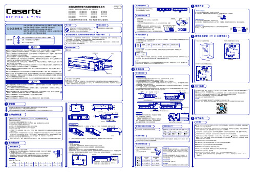
安装结束之前不要扔掉安装所需要的附带零件。
根据安装需要使用标准的安装工具。
机组搬入后到安装完成之前,请用包装保护好机组不被损坏。
本系列机型标准随机附件见装箱单,其它安装时所需的部件,按本公司安装网点要求用户自备。
选择以下地点安装室内机。
(1)空调出风口与地面之间的距离不得大于2.7米。
(2)选择空调出风可以遍及整个房间并且布置连接管,接线,排水管至室外的合适位置。
(3)天花板结构要足以坚固以支撑机组的重量。
(4)连接管,排水管和连接导线能够穿过墙壁连接室内外机组。
(5)室内机组与室外机组间的连接管以及排水管越短越好。
(6)连接法兰由用户自备。
(7)室内机组下方不放置电视机、仪器、设备、艺术品、钢琴、无线电装置等其它贵重物品防止冷凝水滴入造成以上物品的损坏。
(8)选择室内机周围(如安装室内机组的天花板夹层)干球温度30℃以下且相对湿度80%以下的地方。
机组周围若在上述条件以上的高湿度环境下运行时,可能有水滴落下;请给机组整体以及配管、排水管上再增加10~20mm绝热材料(发泡聚乙烯或同等效果材料)。
绝热材料超过10mm时,请压紧嵌入天花板开口内。
(9)室内机回风口不受外部入侵气体影响的地方。
回风口不建议在门口、窗口,如果别无选择可以保持关门、关窗,在节能的同时可以有效减少空调运行异常。
进风格栅的安装室内机风管的安装风机出风的选择1.将通讯线从暗盒穿线孔穿过。
120暗盒线控器后盖①室内机组安装警告:防备大风、地震。
按规定进行安装。
安装不当,会因空调翻倒等造成事故。
注意事项最低最高最低干球: 32℃制冷干球: 18℃干球: 43℃干球: -5℃湿球: 23℃湿球: 14℃湿球: 26℃除湿室内侧室外侧最高最高最低最高最低干球: 27℃干球: 15℃干球: 21℃干球: -15℃湿球: 15℃制热室内侧室外侧空调运行操作范围运行顺序请按说明书进行。
试运行的方法务必请安装人员进行一次试运转,并检查温度调节器工作是否正常?接通室外机电源,向压缩机壳体加热带通电。
考普兰压缩机

泰合华创科技有限公司技术部
T表示电机电压 T三相电压 P单相电压
泰合华创科技有限公司技术部
F压缩机电机保护 F内置式保护器与接触 器联用 S内置式热保护器,电气 内置式热保护器, 传感器和外保护模块, 传感器和外保护模块, 与接触器联用. 与接触器联用.
泰合华创科技有限公司技术部
0150是电机率代码 是电机率代码 0150 1.50匹 1.12KW 匹 0175 1.75匹 1.31KW 匹 0200 2.00匹 1.49KW 匹 0500 5.00匹 3.73KW 匹 备注:每匹输入功率约 备注:每匹输入功率约746W
泰合华创科技有限公司技术部
泰合华创科技有限公司技术部
T表示电机电压 T三相电压 P单相电压
泰合华创科技有限公司技术部
F压缩机电机保护 F内置式保护器与接触器 联用 S内置式热保护器,电气传 内置式热保护器, 感器和外保护模块, 感器和外保护模块,与接 触器联用. 触器联用.
泰合华创科技有限公司技术部
D电气代号50HZ 电气代号50HZ C 200/240V-3 200/240VD 380/420V-3 380/420VE 500-3 500-
泰合华创科技有限公司技术部
考普兰压缩机Copeland 考普兰压缩机 ZR系列全封压缩机 系列全封压缩机 ZR 85KC-TFD - ZR表示机型 (柔性涡旋式 表示机型:(柔性涡旋式) 表示机型 R高温或中温 高温或中温 S表示中温 表示中温 F低温 低温
泰合华创科技有限公司技术部
85表示制冷量 85表示制冷量: 表示制冷量: 是指压缩机在60HZ\ 是指压缩机在60HZ\ARI 工况下的名义制冷量 K表示制冷量系数: 表示制冷量系数: K 1000 M 10000 备注:ARI工况是指在 工况是指在7.2备注:ARI工况是指在7.254.4摄氏度的环境中的工 54.4摄氏度的环境中的工 况.
人民电器 RDCPS系列控制与保护开关电器 产品说明书
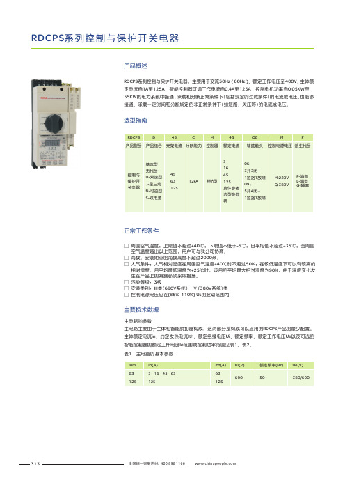
313RDCPS 系列控制与保护开关电器RDCPS 系列控制与保护开关电器,主要用于交流50Hz ( 60Hz )、额定工作电压至400V 、主体额定电流自1A 至125A 、智能控制器可调工作电流自0.4A 至125A 、控制电机功率自0.05KW 至55KW 的电力系统中接通、承载和分断正常条件下(包括规定的过载条件)的电流或电压,也能够接通、承载一定时间和分断规定的非正常条件下(如短路、欠压等)的电流或电压。
□ 周围空气温度:上限值不超过+40℃;下限值不低于-5℃;日平均值不超过+35℃;当周围 空气温度超出以上范围,用户可与我公司协商。
□ 海拔:安装地点的海拔高度不超过2000米。
□ 大气条件:大气相对湿度在周围空气温度+40℃时不超过50%;在较低温度下可以有较高的 相对湿度。
月平均最低温度为+25℃时,该月的平均最大相对湿度为90%,由于温度变化发 生在产品上的凝露必须采取措施。
□ 污染等级:3级□ 安装类别:III 类(690V 系统)、IV (380V 系统)类□ 控制电源电压应在(85%~110%) Us 的波动范围内正常工作条件产品概述选型指南主电路的参数主电路主要由于主体和智能脱扣器构成,这两部分是构成可以应用的RDCPS 产品的最少配置。
主体额定电流in 、约定发热电流Ith 、额定绝缘电压Ui 、额定频率、额定工作电压Ue 以及可选的智能控制器的额定工作电流Ie 范围或控制功率范围见表1、表2。
主要技术数据表1主电路的基本参数314注:□ 瞬时保护参数li 不可调,其值整定在16le电机用产品其短延时保护整定参数ls 可调范围为6lr~12lr □ □ 配电用产品其短延时保护整定参数Is 可调范围为3lr~6lr □ 以上功率范围参考Y 系列三相异步电动机的技术参数 □如有特殊要求时请生产厂家联系表2 主电路的主要参数315RDCPS 系列控制与保护开关电器RDCPS保护特性曲线1.0l r 1最小1.2l r 1最小1.0l r 1最大1.2l r 1最大6l r 1(l r 2最小)12l r 1(l r 2最16l r 1±1520l r 1±20I c s I(A)RDCPS电动机保护时间-电流特性0.1s 0.01s 0.001s1.05l r 1最小1.30l r 1最小1.05l r 1最大1.30l r 1最大3l r 1(l r 2最小)6l r 1(l r 2最大)16l r 1±1520l n ±20%I c sI(A)RDCPS 配电保护时间-电流特性用于电动机控制(使用类别:AC-42、AC-43、AC-44)的动作特性316智能脱扣器主要技术参数□ 起动延时在RDCPS 起动时间内,只对缺相、断相、过压、欠压、欠流、短路、漏电及三相不平衡进行保护,以避免RDCPS 启动大电流和过电流的保护;整定时间为 ( 1~99 ) 秒内之间选择;□ 过压及欠压保护只对辅助电源电压进行保护,以确保线圈与智能控制器正常工作;过压保护:当辅助电源电压超过设定值时(出厂整定在120%Us ),动作时间≤10秒;欠压保护:当辅助电源电压低于设定值时(出厂整定在85%Us ),动作时间≤10秒;□ 反时限过载长延时保护用户根据负载电流I 设定智能脱扣器的额定工作电流Ie ,使负载电流I 在80~100%Ie 之间,动作时间应根据负载特性设定,过流倍数与动作时间特性见表四,反时限过载长延时保护特性曲线出厂设定在F1表3 RDCPS反时限过载长延时保护动作特性用于配电线路负载(使用类别:AC-40、AC-41)的动作特性□ 欠流保护欠流保护:是根据最小电流与额定电流的比值来判断是否启动欠流保护(出厂设定在0),可以对不能空载的电机进行保护;也可以避免用户未根据负载电流I 设定RDCPS 智能脱扣器的工作电流Ie ,从而导致电机不在RDCPS 的保护范围内。
DF22系列各部分的含义

首先将DF22BL-2S-7.29C的料号分为7 部分,具体分法,如下图所示。
下面对各部分进行解释 ①部分的含义是:系列 DF22 ②部分的含义是:表单类型 插座: 空白:标准高度,标准锁 B:长型,标准锁 C:长型,符合人体工程学的锁 在线插头: 空白:面板安装 A:无面板安装
③部分的含义: 指导键类型:空白:内部(颜色:白色) R:右侧(颜色:黑色) L:左侧(颜色:红色) ④部分的含义 针脚数:1、2、3、4、5pin
HRS连接器DF22系列胶壳型号各部分 分别有什么意思
HRS连接器DF22系列胶壳型号有很多 因素组成,具体这些因素代表什么 意义,很多人在用的时候并不知道, 所以在选型方面会遇到很多的麻烦。 今天就帮大家将料号进行解析,在 这里以DF22BL-2S-7.29C为例解释一 下。希望可以帮到有用的人。
⑤部分的含义: 连接器类型: S:插座 DS:双排插座 P:插头 EP:在线插头 DEP:双排在线插头 RS/P:定位器 ⑥部分的含义: 间距:7.92mm ⑦部分的含义: 胶壳类型: C:波纹胶壳 DSA:直头 DS:直角头 没有信息:定位器
比泽尔制冷设备有限公司培训资料

排气量 m3/h (50HZ) 4,06 5,21 6,51 7,58 9,54 11,36 13,42 16,24 18,05 22,72 26,84 32,48
八角型压缩机型号说明 4DC-5.2(Y) 44DC-10.2(Y) 4: 表示-4缸 D: 表示-缸径x行程 C: 表示-八角型 5:表示-5HP 2: 表示-第二代压缩机 44:表示-两台(4缸)对接 Y: 表示-聚脂油(制冷剂 R134a/R404A/507)
北京比泽尔制冷设备有限公司
一:压缩机的型号及型式
八角型系列压缩机
八角型压缩机型号
2KC-05.2 2JC-07.2 2HC-1.2/2.2 2GC-2.2 2FC-2.2/3.2 2EC-2.2/3.2 2DC-2.2/3.2 2CC-3.2/4.2 4FC-3.2/5.2 4EC-4.2/6.2 4DC-5.2/7.2 4CC-6.2
蒸发温度℃
绿色区域 附加冷却
北京比泽尔制冷设备有限公司
2:制冷附件(选购件)的选择 使用及安装方法
北京比泽尔制冷设备有限公司
压缩机是制冷系统的心脏,任何环节出现问题 都会影响压缩机的正常运行。所以正确选择压 缩机的运行范围和附件是保证制冷系统正常运 行的关键。
北京比泽尔制冷设备有限公司
选购件(比泽尔公司提供) 根据不同运行工况,需增加一些附件,作为选购件
北京比泽尔制冷设备有限公司
6):卸载启动(选购件)
目的:压缩机无负载启动,降低启动电流。 一般情况下,采用分线圈启动就不采用卸载启动
使用方法: 使用卸载启动装置在排气管路上需加单向阀和排气温保护
装置。加装单向阀的主要目的是防止压缩机在启动时高压制冷 剂倒流回压缩机。
排气温度传感器的作用是防止在压缩机启动时,卸载启动发生 故障时,导致压缩机排气温度过高而停止压缩机运转。
DF7-3S-3.96C中文资料

3.96 mm Pitch Miniature Connectors for Internal Power Supplies (UL,C-UL and TÜV Listed)
DF7 Series
Complete Locking Function
Completely enclosed locking system
UL/C-UL
TÜV
Item
11. Contact resistance 12. Insulator resistance 13. Withstanding voltage 14. Insertion-Extraction force (per contact) 15. Durability (mating/unmating) 16. Vibration 17. Shock 18. Humidity
8.Cost Effective Tooling
The same crimping tools are used to terminate socket and pin contacts.
9. Prevention of Short Circuits between Adjacent Contacts
6 Applicable Conductor
1618: AWG 16 to AWG 18 2022: AWG 20 to AWG 22 2426: AWG 24 to AWG 26
7 Packaging
SCF: Socket contacts / Reel SC: Socket contacts / Bag PCF: Plug contacts / Reel PC: Plug contacts / Bag
2. Increased Contact Retention of Crimped Contacts and Prevention of Incomplete Insertion
国家法兰标准GB9119-2000

332 3 34 276 18.90
300 325
485
430
30
16
M27
390 4 36 328 26.80
350 377 555/550
490
40
16
M30
448 4 42 380 34.35
400 426 620/610
550
36/34
16 M33/M30
505 4 44 430 44.90
350
377
505/500
460
23
16
M20
428 4 28 380 16.90
400
426
565
515
26/25 16 M24/M22 482 4 30 430 21.80
450
480
615
565
26/25 20 M24/M22 532 4 30 484 24.40
500
530
670
620
26/25 20 M24/M22 585 4 32 534 27.70
密封尺寸 法兰 法兰
厚度 内径 d fC B
法兰 理论 重量 kg
10 14
90
60
14
4
M12
40 2 16 15 0.64
15 18
95
65
14
4
M12
45 2 16 19 0.80
20 25
105
75
14
4
M12
55 2 18 26 0.99
25 32
115
85
14
4
M12
65 2 18 33 1.18
60
R22冷媒普通家用空调器07冷冻年度机型配置简述及参数1

R22 冷媒
序 号
1 2 3 4 5 6
06.11.27
机型型号
KC-34/06
类 型
等 级
外 机型代码 内 机 型
340101C02R03 340101C01R06 500101C02R11 (片距:1.6) (片距:1.6) (片距:1.7) K型 亲光 1.45) (片距:
1180 1210 1510 1700 1730 2180 1350 1380 1330 1430 2230
RH277VHYC(40) RH277VHYC(40) TS36VDEC(50) TS36VDEC(50) TS36VDEC(50) PH420X3CS-8KUC1(50) RH277VHYC(40) RH277VHYC(40) TS31VDEC(50) TS36VDEC(50) PH420X3CS-8KUC1 (50) TS36VDEC(50) PH420X3CS-8KUC1 (50) TS36VDEC(50)
PP060002
2006.1.18
K、V通用
500703G02R03 500703G01R03 600701G19R03 700702G02R03 700702G01R03
18NV 18NV款塑料件 18NV款塑料件 (片 距:1.5) 24NV (片距:1.5) 24NV (片距:1.5) 24NV 亲肋 1.5) (片距:
850
K060193
PP060117
2006.10.28
K、P、M、F通用
KF-34GW/F2 (PH180) KFR-34GW/F2 G (PH180) KFR-34GW/F2
B 低 价
340301G02R01 340301G01R01 340307G01R02
DF22-2DEP-7.92C中文资料
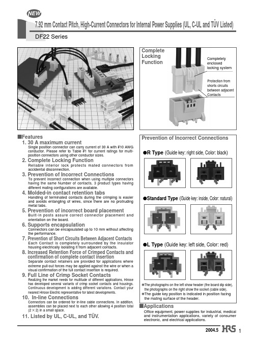
7.92 mm Contact Pitch, High-Current Connectors for Internal Power Supplies (UL, C-UL and TÜV Listed)
DF22 Series
Complete Locking Function
5. Prevention of incorrect board placement
Built-in posts assure correct connector placement and orientation on the board.
6. Supports encapsulation
Connectors can be encapsulated up to 10 mm without affecting the performance.
*The guide key position is indicated in position facing the mating surface of the header.
sApplications
Office equipment, power supplies for industrial, medical and instrumentation applications, variety of consumer electronic, and electrical applications.
8. Increased Retention Force of Crimped Contacts and confirmation of complete contact insertion
Separate contact retainers are provided for applications where extreme pull-out forces may be applied against the wire or when a visual confirmation of the full contact insertion is required.
固纬 ASR-002 三相电源控制器使用手册说明书
三相电源控制器ASR-002使用手册ISO-9001 CERTIFIED MANUFACTURER本手册所含资料受到版权保护,未经固纬电子实业股份有限公司预先授权,不得将手册内任何章节影印、复制或翻译成其它语言。
本手册所含资料在印制之前已经过校正,但因固纬电子实业股份有限公司不断改善产品,所以保留未来修改产品规格、特性以及保养维修程序的权利,不必事前通知。
固纬电子实业股份有限公司台湾省新北市土城区中兴路7-1号T able of Contents3目录安全说明 (4)产品介绍 (7)ASR-002概述 (7)前面板 (8)后面板 (11)操作 (13)基本操作 (14)高级设置 (16)相角设置 (18)电压斜坡设置 (19)扫频设置 (20)单位设置值显示 (21)电线连接&配件 (24)附录 (26)ASR-002 尺寸 (26)使用机架安装套件 (27)指令列表 (29)ASR-002错误信息 (30)ASR-002 Series User Manual4安全说明本章节包含操作和存储时必须遵照的重要安全说明。
在操作前请详细阅读以下内容,确保安全和最佳化的使用。
安全符号这些安全符号会出现在手册或本机中。
警告 警告: 产品在某一特定情况下或实际应用中可能对人体造成伤害或危及生命。
注意 注意:确保环境或使用以防对本机或其它工具造成损坏。
注意高压。
请参阅手册。
保护接地端子。
接地(大地)端子。
勿将电子设备作为未分类的市政废弃物处理。
请单独收集处理或联系设备供应商。
5安全指南通常注意 ∙ 勿将重物置于ASR-002上。
∙避免严重撞击或不当放置而损坏 ASR-002。
∙避免静电释放至ASR-002。
∙请使用匹配的连接线,切不可用裸线连接。
∙不要堵塞冷却风扇开口。
∙若非专业技术人员,请勿自行拆装仪器。
∙ 如果设备未按制造商规定的方式使用,设备提供的保护可能会受损。
电源警告 ∙ AC 输入电压档位: 230 ~240Vac∙ 频率: 50/60 Hz∙ 将交流电源插座的保护接地端子接地,避免电击触电清洁ASR-002 ∙ 清洁前先切断电源∙ 以中性洗涤剂和清水沾湿软布擦拭仪器。
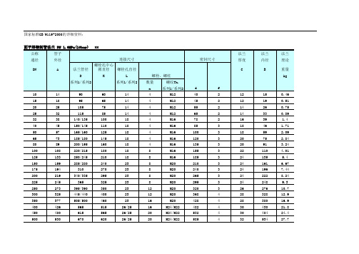
法兰管路螺栓尺寸对照表
575
576
4
600
630
890
795
48/54
20
M45/M48
730
675/677 676/678
5
700
720
995
900
48/54
24
M45/M48
825
777/767 778/768
5
800
820
140/1135
1030
58
24
M52
960
882\875 883/876
5
凹凸面对焊钢制管法兰 PN 6.4MPa(64bar) MM
145
18
8
M16
120
109
110
3
80
89
200/195
160
18
8
M16
135
120
121
3
100
108
235/230
190
23
8
M20
160
149
150
3
125
133
270
220
26/25
8
M24/M22
188
175
176
3
150
159
300
250
26/25
8
M24/M22
218
203
204
5
900
920
1115/1110
1050
34
28
M30
1005
5
1000
1020
1230/1220
1160
36/34
28
Z-15EW22R中文资料(omron)中文数据手册「EasyDatasheet-矽搜」

Z-15EW22R中文资料(omron)中文数据手册「EasyDatasheet-矽搜」畅销基本开关风雨桥高精度,品种全15 A大交换容量高重复精度.分接触,防护持接触,并可调触点间隙类型.一系列标准模型微小负载可用.一系列集成安全模终端款型终端防护护盖可用.Be s ure to read Safety Precautions on page 22 and Safety Precautionsfor All Basic Switches.型号结构构造基本款一般用途防滴如果没有终端防护护盖随着终端防护护盖模压终端分割接触模型防护持接触模型一般用途一般用途参见第3页.请参阅第5页.请参阅第5页.请参阅第2页.参见第4页.参见第4页.基本模式一般用途各种执行机构可用于广泛应用范围.机型为微小负载触点机制与金合金触点,这确防护微小负载高度可靠操作交叉型.触点间隙:H2:0.32毫米(超高灵敏度)H:0.25毫米(高灵敏度,微电压电流负载)摹:0.5毫米(标准)1.8毫米(高容量)F:1.0毫米(分割接触型)分割接触模型这种类型是在结构上不同之处在于它具有两对同时演技触点通过拆分移动触点通用基本开关相同.由于移动触点被连接到一公共端,并联或串联连接是可能.如果模型被用作双触点开关高度可靠微负载切换得到防护证.防护持接触模型所维护接触型具有在开关壳体底部有一个复位键,除位于复位按钮相对侧上按键(柱塞).使用这些按钮交替进行.由于该开关具有比超程更大预行程,很适合在正反转控制电路中使用,手动复位电路,安全限制电路,以及其它电路这是不优选自动复位. (有关详细信息,请参照各数据表.)防滴这些交换机使用一个橡胶套管上情况之间致动器和粘合剂填充和覆盖,以增加耐滴水.模型与防滴端子防护护盖并用树脂充填模终端也可提供.Z型号图例基本模式标准型号(防滴型/模压端子)子)Z-@@@@-@(1)(2)(3)(4) (5)(1)评定0115H2H G E None S D K K3Q3Q Q8Q22Q21L L2W21W W3W32W4W44W78W52W22W2W25W49W54W2277M M 22M 2NJ NJS None 55A 55:0.1 A (微负荷): 15 A:0.20(超高灵敏度)0.25毫米(高感光度,微负载):0.5毫米(标准)1.8毫米(高容量):::::::::::::::::::::::::::::::引脚柱塞超薄弹簧柱塞短弹簧柱塞弹簧柱塞(中OP )弹簧柱塞(高OP )面板安装柱塞(中OP)面板安装柱塞(中OP)面板安装柱塞(高OP )面板安装滚轮柱塞面板安装交叉滚子柱塞板簧(高)辊钢板弹簧短铰链杆铰链杆(低)铰链杆(介质)铰链杆(高)小力铰杆长铰链杆小力线铰链杆(低)小力线铰链杆(高)短铰链滚轮摇臂铰链滚轮摇臂铰链摆杆(大滚子)短铰链交叉滚子杠杆铰链交叉滚子杠杆单向短铰链摆杆(低)反向铰链杆反向短铰链滚轮lever反向铰链滚轮摇臂柔性杆(高)柔性杆(低)Z-@55-M@@@M(1)(2)(3) (4)(1)防滴型(2)铅奥特莱斯None 19: V SF : V CTD 型R 型(2)触点间隙(3)四通八达奥特莱斯(见下L 型图.)L R D:剩下:对:降序(3)执行器铅(4)长度奥特莱斯13: 1m : 3m分割接触模型防护持接触模型Z-10F@Y-B(1) (2)(3)(4) (5)(1)评定10F None S D Q Q22W W22W2M 22:10 A (分割接触型)1毫米(高容量):::::::::引脚柱塞超薄弹簧柱塞短弹簧柱塞面板安装柱塞面板安装滚轮柱塞铰链杆短铰链滚轮摇臂铰链滚轮摇臂反向短铰链滚轮leverZ-15-E@R(1) (2)(3)(4)(1)评定15E None S WR: 15 A1.8毫米(高容量):销柱塞:修身弹性活:铰链杆:维护接触模型(2)触点间隙(3)执行器(2)触点间隙(3)执行器(4)结构(4)施工YB:拆分接触模型:螺丝端子(有齿焊盘圈)(5)终端防护护(4)学位:一般用途:防滴(不包括端子):防滴(包括终端):焊接端子:螺丝端子(有齿焊盘圈):螺丝端子与终端盖(适用于Z-15G @ A 55只)(5)终端None B B5VNote: For combinations of models , OrderingInform ation on page 3 to 6.Z 订购信息主机基本型号(通用)分类执行器触点间隙规范G (0.5 mm) ModelZ-15GZ-15G-BZ-15GSZ-15GS-BZ-15GDZ-15GD-BZ-15GQ3Z-15GQ3-B Z-15GQZ-15GQ-BZ-15GQ8Z-15GQ8-B Z-15GQ22 Z-15GQ22-B Z-15GQ21 Z-15GQ21-B Z-15GLZ-15GL-BZ-15GL2Z-15GL2-B Z-15GW21 Z-15GW21-B 高灵敏度H (0.25 mm) ModelZ-15HZ-15HSZ-15HS-BZ-15HDZ-15HD-B特高灵敏度H2 (0.20 mm)ModelZ-15H2Z-15H2-B高容量E (1.8 mm)ModelZ-15EZ-15E-B微型载H (0.25 mm)ModelZ-01HZ-01H-BZ-01HSZ-01HS-BZ-01HDZ-01HD-B引脚柱塞超薄弹簧柱塞短弹簧柱塞面板安装柱塞Low OP 媒质OP High OP面板安装滚轮柱塞面板安装交叉滚轮柱塞钢板弹簧辊钢板弹簧短铰链杆LowOP铰链杆媒质OPHighOP小力铰链leverLow-力线hingelever短铰链滚轮lever短铰链交叉滚轮摇臂铰链滚轮lever Stan- dardLarge滚筒LowOPHighOP---------Z-15EDZ-15ED-B ---Z-15HQZ-15HQ-B ------Z-15EQ Z-15EQ-B ---Z-01HQZ-01HQ-B ---Z-15HQ22 Z-15HQ22-B Z-15HQ21 Z-15HQ21-B ------------------Z-15EQ22 Z-15EQ22-B Z-15EQ21Z-15EQ21-B ---------------------------Z-15HWZ-15HW-B ---------Z-15GWZ-15GW-B Z-15GW3Z-15GW3-B Z-15GW32 Z-15GW32-B Z-15GW4Z-15GW4-B ------------Z-15HW24 Z-15HW24-B Z-15HW78 Z-15HW78-BZ-15HW52Z-15HW52-BZ-15HW22Z-15HW22-B--------------------- Z-15GW22Z-15GW22-BZ-15GW49Z-15GW49-BZ-15GW2Z-15GW2-BZ-15GW25Z-15GW25-BZ-15GW54Z-15GW54-BZ-15GW2277------Z-15EW22Z-15EW22-BZ-01HW22Z-01HW22-B---Z-15HW2Z-15HW2-B------------------------------------------------------------------------------------铰链交叉滚子lever单向短铰链滚轮摇臂反向铰链杆*2反向短铰链滚轮摇臂*2反向铰链Z-15GW2277-BZ-15GMZ-15GM-BZ-15GM22Z-15GM22-BZ-15GM2Z-15GM2-B*1.: Solder terminal: Screw terminal*2. The pin plungers of revers e-type models are continuous ly pres s ed by the actuator levers with compres s ion coil s prings and the pin plungers are freed by operating the levers. Revers e-type models are highly vibration- and s hock-res is tive becaus e the pin plungers are normally pres s ed.附件(端子盖,执行器和分离器):参照Z / A / X / DZ通用附件和Z / X / DZ常用配件.Z最小起订量批号以下型号可在以下规定最低订单很多.订单必须放在每手.分类执行器短弹簧柱塞面板安装柱塞面板安装滚轮柱塞面板安装交叉滚子柱塞短铰链杆铰链杆小力铰杆小力铰链线杆铰链滚轮摇臂反向短铰链滚轮lever 反向铰链滚轮摇臂规范Z-15GD-BZ-15GQZ-15GQ-BZ-15GQ8-BZ-15GQ22Z-15GQ22-BZ-15GQ21-BZ-15GW21-BZ-15GWZ-15GW-BZ-15GW4-B---Z-15GW22Z-15GW22-BZ-15GW2Z-15GW2-BZ-15GM22-BZ-15GM2-B高灵敏度------------------Z-15HW24-BZ-15HW78-B------------起码为很多(PCS)10分割接触模型执行器引脚柱塞超薄弹簧柱塞短弹簧柱塞面板安装柱塞面板安装滚轮柱塞铰链杆短铰链滚轮lever铰链滚轮摇臂反向短铰链滚轮摇臂*2触点间隙终奌站*1F (1.0 mm)Model---Z-10FY-B防护持接触模型执行器引脚柱塞超薄弹簧柱塞铰链杆ModelZ-15ERZ-15ESRZ-15EWR ---Z-10FSY-B---Z-10FDY-B---Z-10FQY-B---Z-10FQ22Y-B---Z-10FWY-B---Z-10FW22Y-B---Z-10FW2Y-B---Z-10FM22Y-B*1.: Solder terminal: Screw terminal*2. The pin plungers of revers e-type models are continuous ly pres s ed by the actuator levers with compres s ion coil s prings and the pin plungers are freed by operating the levers. Revers e-type models are highly vibration- ands hock-res is tive becaus e the pin plungers are normally pres s ed.Z基本模式(防滴型号标准,微小负载)规范G (0.5 mm)不提供ModelZ-15G55Z-15G55-B Z-15GD55Z-15GD55-B分类触点间隙防滴端子防护护套执行器引脚柱塞短弹簧柱塞Low OP High OP面板安装柱塞面板安装滚轮柱塞面板安装交叉滚轮柱塞钢板弹簧辊钢板弹簧短铰链杆长铰链杆铰链杆短铰链滚轮摇臂铰链滚轮摇臂终奌站*1微型载H (0.25 mm)提供Model ---Z-15GA55-B5V不提供ModelZ-01H55Z-01H55-B Z-01HD55Z-01HD55-B---------Z-15GK3A55-B5VZ-15GK55Z-15GK55-B Z-15GK355Z-15GK355-B Z-15GQ55Z-15GQ55-B Z-15GQ2255Z-15GQ2255-B------------------------------Z-01HW2255Z-01HW2255-B弹簧柱塞---Z-15GQA55-B5V---Z-15GQ22A55-B5V---Z-15GQ2155-B Z-15GL55Z-15GL55-B Z-15GL255Z-15GL255-B Z-15GW2155Z-15GW2155-B Z-15GW4455Z-15GW4455-B Z-15GW55Z-15GW55-B Z-15GW2255Z-15GW2255-B Z-15GW255Z-15GW255-B ---Z-15GQ21A55-B5V------------Z-15GW44A55-B5V---Z-15GWA55-B5V---Z-15GW22A55-B5V---Z-15GW2A55-B5V---单向短铰链滚轮摇臂反向铰链杆*2反向短铰链滚轮摇臂*2反向铰链滚轮lever *2柔性杆(螺旋弹簧)*3Z-15GW227755Z-15GW227755-BZ-15GM55Z-15GM55-B Z-15GM2255Z-15GM2255-B Z-15GM255Z-15GM255-BZ-15GNJ55---Z-15GW2277A55-B5V------------------------Z-15GNJ55-B---*1.: Solder terminal : Screw terminal*2. The pin plungers of revers e-type models are continuous ly pres s ed by the actuator levers with compres s ion coil s prings and the pin plungers are freed by operating the levers .*3. The tip is made of res in.最小起订量批号以下型号可在以下规定最低订单很多.订单必须放在每手.ClassificationActuatorSpring plunger Hinge leverContact gapShort spring plunger Standard G (0.5 mm)Z-15GD55-B Z-15GK55-B Z-15GW4455-B Z-15GW55Z-15GW55-B Minimum orderlot (pcs)10Short hinge roller lever Hinge roller leverFlexible rod (coil spring)Z-15GW2255Z-15GW2255-B Z-15GW255-B Z-15GNJ55-B附件(端子盖,执行器和分离器):参照Z / A / X / DZ 通用附件和Z / X / DZ 常用配件.。
实验五--苯妥英钠制备

苯妥英钠为白色粉 于乙醇,几乎不溶于乙醚 渐吸收二氧化碳,分解成 合成路线如下: 实验五苯妥英钠(PHenytoin Sodium )的合成一、 实验目的1、 学习安息香缩合反应的原理和应用维生素 B 1为催化剂进行反应的机理和实验 方法。
2、 了解稀硝酸作为氧化剂的实验方法。
二、 实验原理苯妥英钠为抗癫痫药,适于治疗癫痫大发作,也可用于三叉神经痛,及某些类型的心律不齐。
苯妥英钠化学名为 5, 5-二苯基乙内酰脲,化学结构式为:末,无臭、味苦。
易溶于水,能溶 和氯仿。
微有引湿性,在空气中渐 苯妥英。
表1化合物理化性质CHO Vit B CH 1 OH HNO 3 C —— I.H 2NCONH 2,NaOH 2.HCI C 6 化合物名称 性状 熔点/ c 溶解度 分子量 水 乙醇 安息香(二苯乙醇酮) 白色针状晶 体 133 不溶于冷水,微溶于热水 溶 212.25 二苯乙二酮 黄色针状晶 体 95-96 不溶 溶 210.22 苯妥英 白色可见针 状晶体 293-295 -- --252.268 NaOH H 2O三、实验材料与设备表2玻璃仪器及规格名称规格数量锥形瓶250ml1冰水浴缸--1漏斗--1三颈瓶100ml1球形冷凝管--1干燥管(连有导气管)--1量筒100ml1量筒50ml1烧杯250ml2烧杯50ml若干抽滤瓶--1滴管1ml2表3设备型号及规格设备名称型号厂家电热恒温鼓风干燥箱DHG-9023A上海精宏实验设备有限公司真空干燥箱DZF-6020上海精宏实验设备有限公司集热式恒温加热磁力搅拌器DF-101S郑州长城科工贸有限公司磁力搅拌器85-1A郑州长城科工贸有限公司电子天平e=10d塞多丽斯科学仪器有限公司循环水真空泵SHB-m郑州长城科工贸有限公司显微熔点仪SGW X-4上海精密科学仪器有限公司表4试剂及规格名称厂家规格用量苯甲醛天津市大茂化学试剂厂分析纯22.5ml 硝酸浙江三鹰化学试剂有限分析纯20ml公司VB1广东光华化学厂有限公生化试剂BR6g司脲宁波市化学试剂厂分析纯 1.5g二甲基硅油天津市大茂化学试剂厂分析纯AR1000ml分析纯话量无水乙醇浙江三鹰化学试剂有限司出品浓盐酸衡阳市凯信化工试剂有分析纯AR90ml限公司氢氧化钠中国上海试剂总厂分析纯AR适量四.实验操作步骤(一)安息香的制备1. 于锥形瓶内加入VB 6g、水30 mL、无水乙醇60 mL (水和无水乙醇提前冰水冷去卩)。
Schneider Electric ATS22C59Q 软启动器产品说明书

T h e i n f o r m a t i o n p r o v i d e d i n t h i s d o c u m e n t a t i o n c o n t a i n s g e n e r a l d e s c r i p t i o n s a n d /o r t e c h n i c a l c h a r a c t e r i s t i c s o f t h e p e r f o r m a n c e o f t h e p r o d u c t s c o n t a i n e d h e r e i n .T h i s d o c u m e n t a t i o n i s n o t i n t e n d e d a s a s u b s t i t u t e f o r a n d i s n o t t o b e u s e d f o r d e t e r m i n i n g s u i t a b i l i t y o r r e l i a b i l i t y o f t h e s e p r o d u c t s f o r s p e c i f i c u s e r a p p l i c a t i o n s .I t i s t h e d u t y o f a n y s u c h u s e r o r i n t e g r a t o r t o p e r f o r m t h e a p p r o p r i a t e a n d c o m p l e t e r i s k a n a l y s i s , e v a l u a t i o n a n d t e s t i n g o f t h e p r o d u c t s w i t h r e s p e c t t o t h e r e l e v a n t s p e c i f i c a p p l i c a t i o n o r u s e t h e r e o f .N e i t h e r S c h n e i d e r E l e c t r i c I n d u s t r i e s S A S n o r a n y o f i t s a f f i l i a t e s o r s u b s i d i a r i e s s h a l l b e r e s p o n s i b l e o r l i a b l e f o r m i s u s e o f t h e i n f o r m a t i o n c o n t a i n e d h e r e i n .Product data sheetCharacteristicsATS22C59Qsoft starter-ATS22-control 220V-power230V(160kW)/400V(315kW)/440V(355kW)MainRange of product Altistart 22Product or component typeSoft starterProduct destination Asynchronous motorsProduct specific appli-cationSevere and standard applications Component name ATS22Network number of phases3 phasesPower supply voltage 230...440 V (- 15...10 %)Motor power kW355 kW at 440 V 315 kW at 400 V 160 kW at 230 V Factory setting current 560 APower dissipation in W 251 W for standard applications Utilisation category AC-53AType of start Start with torque control (current limited to 3.5 In)Icl nominal current 590 A (connection in the motor supply line) for stan-dard applications IP degree of protectionIP00ComplementaryAssembly style With heat sink Function available Internal bypass Power supply voltage limits 195...484 VPower supply frequency 50...60 Hz (- 10...10 %)Network frequency 45...66 HzDevice connection In the motor supply lineTo the motor delta terminals Control circuit voltage 220...230 V -15...10 % at 50/60 Hz Control circuit consumption 20 W Discrete output number 2Discrete output type(R2)Relay outputs 230 V running, alarm, trip, stopped, not stopped, starting,ready, C/O(R1)Relay outputs 230 V running, alarm, trip, stopped, not stopped, starting,ready, C/OMinimum switching current Relay outputs 100 mA at 12 V, DCMaximum switching currentRelay outputs 2 A at 30 V, DC inductive load, L/R = 7 msRelay outputs 2 A at 250 V, AC inductive load, cos phi = 0.4, L/R = 20 ms Relay outputs 5 A at 30 V, DC resistive load, cos phi = 1Relay outputs 5 A at 250 V, AC resistive load, cos phi = 1Discrete input number 3Discrete input type (LI1, LI2, LI3)logic 5 mA 4.3 kOhm Discrete input voltage 24 V (<= 30 V)Discrete input logic (LI1, LI2, LI3)positive logic state 0 < 5 V and < 2 mA state 1 > 11 V and > 5 mA Output current 0.4...1 Icl adjustable PTC probe input750 Ohm Communication port protocol Modbus Connector type1 RJ45Communication data link SerialPhysical interfaceRS485 multidropTransmission rate4800, 9600 or 19200 bpsMax nodes number31Protection type Thermal protection on starterThermal protection on motorPhase failure on lineMarking CEType of cooling Forced convectionOperating position Vertical +/- 10 degreeHeight455 mmWidth304 mmDepth339.7 mmProduct weight50 kgEnvironmentElectromagnetic compatibility Voltage/Current impulse conforming to IEC 61000-4-5 level 3Immunity to radiated radio-electrical interference conforming to IEC 61000-4-3level 3Immunity to electrical transients conforming to IEC 61000-4-4 level 4Electrostatic discharge conforming to IEC 61000-4-2 level 3Damped oscillating waves conforming to IEC 61000-4-12 level 3Conducted and radiated emissions conforming to IEC 60947-4-2 level A Standards EN/IEC 60947-4-2Product certifications CCCCSAC-TickGOSTULVibration resistance 1.5 mm (f = 2...13 Hz) conforming to EN/IEC 60068-2-61 gn (f = 13...200 Hz) conforming to EN/IEC 60068-2-6Shock resistance15 gn for 11 ms conforming to EN/IEC 60068-2-27Noise level56 dBPollution degree Level 2 conforming to IEC 60664-1Relative humidity<= 95 % without condensation or dripping water conforming to EN/IEC 60068-2-3 Ambient air temperature for operation> 40...< 60 °C with current derating 2.2 % per °C-10...40 °C without deratingAmbient air temperature for storage-25...70 °COperating altitude> 1000...< 2000 m with current derating of 2.2 % per additional 100 m<= 1000 m without deratingOffer SustainabilitySustainable offer status Not Green Premium productRoHS Compliant - since 0939 -Schneider Electric declaration of conformity Product environmental profile Available Download Product EnvironmentalProduct end of life instructions Available Download End Of Life ManualDimensions DrawingsFrame Size E DimensionsMounting and ClearancePrecautionsStandardsThe Altistart 22 soft starter is compliant with pollution Degree 2 as defined in NEMA ICS1-1 or IEC 60664-1.DANGERAir CirculationLeave sufficient free space to help the air required for cooling purposes to circulate from the bottom to the top of the unit.OverheatingTo avoid the soft starter to overheat, respect the following recommendations:●Mount the Altistart 22 Soft Starter within ± 10° of vertical.●Do not locate the Altistart 22 Soft Starter near heat radiating elements.●Electrical current through the Altistart 22 Soft Starter will result in heat losses that must be dissipated into the ambient air immediatelysurrounding the soft starter. To help prevent a thermal fault, provide sufficient enclosure cooling and/or ventilation to limit the ambient temperature around the soft starter.●If several soft starters are installed in a control panel, arrange them in a row. Do not stack soft starters. Heat generated from the bottomsoft starter can adversely affect the ambient temperature around the top soft starter.Wall mounted or Floor-standing Enclosure with IP 23 Degree of protectionIntroductionTo help proper air circulation in the soft starter, grilles and forced ventilation can be installed.Ventilation GrillesForced Ventilation UnitProduct data sheetConnections and SchemaATS22C59QPower TerminalBar StylePower supply and output to motor Barb 40 mm (1.18 in)a5 mm (0.2 in)BoltM12 (0.47 in)Cable and protective cover Size 2X240 mm²Gauge2X500 MCM Protective cover LA9F703Tightening torque 57 N.m498.75 lb.inPower connections, minimum required wiring section230 Vac control, logic Inputs (LI) 24 Vdc, 3-wire control With Line Contactor, Freewheel or Controlled Stop230 Vac control, logic Inputs (LI) 24 Vdc, 2-wire control,freewheel stopConnection in the motor delta winding in series with each windingWiringATS22 soft starters connected to motors with the delta connections can be inserted in series in the motor windings.The following wiring requieres particular attention. It is documented in the Altistart 22 Soft start - soft stop unit user manual. Please contact Schneider Electric commercial organisation for further informations.ExampleA 400 V - 110 kW motor with a line current of 195 A (nominal current for the delta connection). The current in each winding is equal to 195/1.5 or 130 A. The rating is determined by selecting the soft starter with a permanent nominal current (ICL) just above this current.Product data sheetPerformance CurvesATS22C59QMotor Thermal Protection - Cold CurvesCurvesA Class 10B Class 20C Class 30Trip time for a Standard Application (Class 10)3.5 ln 32 sTrip time for a Severe Application (Class 20)3.5 ln 63 sTrip time for a Severe Application (Class 30)3.5 ln 95 sMotor Thermal Protection - Warm CurvesCurvesA Class 10B Class 20C Class 30Trip time for a Standard Application (Class 10)3.5 ln 16 sTrip time for a Severe Application (Class 20)3.5 ln 32 sTrip time for a Severe Application (Class 30)3.5 ln 48 s。
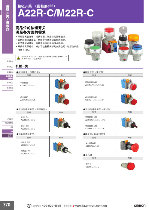
A22R-C_M22R-C
䆶⬉䆱
400-820-4535
᳔ᮄֵᙃ
771
1a 1a ᑇᔶᣝ䪂 1a 1b 1b ᖂࡼᓔ݇ 䰤ԡᓔ݇ ⎆ԡ䆒 A22R-Tƶ-ƶƶ-C 1a 1a 1a 1a 1a ߌߎᣝ䪂 1a 1b 1b @ⱘݙ䆄ো M:㞾/A:㞾䫕 A22RL-Fƶ-ƶ-ƶƶ-C ᑇᔶᣝ䪂 ѸⳈ⌕24V
ߌߎᏺ♃ᣝ䪂 A22RL-Tƶ-ƶ-ƶƶ-C
ƽᮟ䪂ൟ䗝ᢽᓔ݇˄ϡᏺ♃ൟ˅
ൟো
ᮟ䪂2ԡ
ѻક䗝ൟ
ƽᮟ䪂ൟ䗝ᢽᓔ݇˄ᏺ♃ൟ˅
ᔶ⢊ ൟো
ᏺ♃ᮟ䪂2ԡ A22RW-2ƶƶ-ƶ-ƶ-C ᏺ♃ᮟ䪂3ԡ A22RW-3 ƶƶ-ƶ-ƶ-C
ᔶ⢊
A22RS-2ƶ-ƶ-C ᮟ䪂3ԡ A22RS-3ƶ-ƶ-C
ƽ䩹࣭ൟ䗝ᢽᓔ݇
ƽᣝ䪂ൟᏺ♃ᣝ䪂ൟ
㾖 A22RL-Tƶ-ƶ-ƶƶ-C ߌߎᣝ䪂 ѸⳈ⌕24V 㾘Ḑ ᓔ݇买㡆 ⚍ᵘ៤ 1a 1a 1a 1a 1a 1a 1a ߌߎᣝ䪂 Ѹ⌕220V 1a 1a 1a @ⱘݙ䆄ো M:㞾/A:㞾䫕 ൟো A22RL-TW-24A-10ƶ-C A22RL-TG-24A-10ƶ-C A22RL-TR-24A-10ƶ-C
型号标准
ƽ༫㺙કൟোA22Rƶ-ƶƶ-ƶ-ƶƶ-Cᣝ䪂ൟˈᏺ♃ᣝ䪂ൟ
ᰒ冫♃
A22R@-@@- @-@@-C
ķ ĸ Ĺ ĺ Ļļ ķ辵㉏
ĸ᪡䚼ᔶ⢊
辵㉏ ϡᏺ♃ ᏺ♃ 䆄ো F T 辵㉏ ᑇᔶ ߌߎ
Ĺ᪡䚼买㡆 䆄ো R G Y W A B 㡆 㑶 㓓 咘 ⱑ 㪱 咥*
ĺ⑤ܝ 䆄ো ᮴ 6A 12A 24A Փ⫼⬉य़ ϡᏺ♃ AC/DC6V AC/DC12V AC/DC24V
0.5
- 1、下载文档前请自行甄别文档内容的完整性,平台不提供额外的编辑、内容补充、找答案等附加服务。
- 2、"仅部分预览"的文档,不可在线预览部分如存在完整性等问题,可反馈申请退款(可完整预览的文档不适用该条件!)。
- 3、如文档侵犯您的权益,请联系客服反馈,我们会尽快为您处理(人工客服工作时间:9:00-18:30)。
3. Prevention of Incorrect Connections
To prevent incorrect connection when using multiple connectors having the same Number of contacts, 3 product types having different mating configurations are available.
qStandard Type (Guide key: inside, Color: natural)
5. Prevention of incorrect board placement
Built-in posts assure correct connector placement and orientation on the board.
Measured with a steel pin of 1.6 x 0.8 ± 0.002 thickness 30 cycles Frequency 10 to 55 Hz, single amplitude of 0.75 mm, 3 axis, duration of 2 hours Acceleration of 490 m/s2, 11 ms duration, sine half-wave waveform, 3 cycles in each of the 3 axis. Temperature 40ç ± 2ç, 90% to 95% RH, 96 hours (-55ç: 30 minutes➝ 5 to 35ç: 5 minutes➝85ç: 30 minutes➝5 to 35ç: 5 minutes) for 5 cycles Re-flow solder temperature 250ç, for 10 seconds Manual soldering: Soldering iron temperature 300ç, 3 seconds
10. In-line Connections
Connectors can be ordered for in-line cable connections. In addition, assemblies can be placed next to each other allowing 4 position total (2 ∞ 2) in a small space.
元器件交易网 NEW
7.92 mm Contact Pitch, High-Current Connectors for Internal Power Supplies (UL, C-UL and TÜV Listed)
DF22 Series
Complete Locking Function
11. Listed by UL, C-
1
元器件交易网
sProduct Specifications
Current rating Ratings AWG10 Number of contacts 1 30A 2 25A 3 25A 4 22A 5 22A Specification UL/C-UL TÜV AWG12 25A 20A 20A 18A 18A AWG14 AWG16 20A 15A 18A 15A 18A 15A 15A 13A 15A 13A AC/DC 1000V AC/DC 600V AC/DC 600V Operating temperature range -35ç to 85ç (Note 1) Operating humidity range 20% to 80% Storage temperature range -10ç to 60ç (Note 2) Storage humidity range 40% to 70% (Note 2) UL/C-UL/TÜV UL C-UL TÜV File No. and Recognition No. : E52653 : E52653 : R9950703
9. Full Line of Crimp Socket Contacts
Realizing the market needs for multitude of different applications, Hirose has developed several variants of crimp socket contacts and housings. Continuous development is adding different variations. Contact your nearest Hirose Electric representative for latest developments. *The photographs on the left show header (the board dip side), the photographs on the right show the socket (cable side). *The guide key position is indicated in position facing the mating surface of the header.
Each Contact is completely surrounded by the insulator housing electrically isolating it from adjacent contacts.
qL Type (Guide key: left side, Color: red)
6. Supports encapsulation
Connectors can be encapsulated up to 10 mm without affecting the performance.
7. Prevention of Short Circuits Between Adjacent Contacts
Voltage rating Item 1. Contact resistance 2. Insulator resistance 3. Withstanding voltage
Specification Contact resistance(Initial value): 5 m ohms max. 1000 M ohms min. No flashover or Insulator breakdown 0.3N min., 5N max. Contact resistance of 10 m ohms max. No electrical discontinuity of 1 µs. min. No electrical discontinuity of 1 µs. min. Contact resistance 10 m ohms max. Contact resistance of 10 m ohms max. No deformation of the insulator parts affecting performance 20mV max., 1mA 1000 V DC 2500 V AC for 1 minute
8. Increased Retention Force of Crimped Contacts and confirmation of complete contact insertion
Separate contact retainers are provided for applications where extreme pull-out forces may be applied against the wire or when a visual confirmation of the full contact insertion is required.
Completely enclosed locking system
Protection from shorts circuits between adjacent Contacts
sFeatures
1. 30 A maximum current
Single position connector can carry current of 30 A with #10 AWG conductor. Please refer to Table #1 for current ratings for multiposition connectors using other conductor sizes.
4. Molded-in contact retention tabs
Handling of terminated contacts during the crimping is easier and avoids entangling of wires, since there are no protruding metal tabs.
sApplications
Office equipment, power supplies for industrial, medical and instrumentation applications, variety of consumer electronic, and electrical applications.
Prevention of Incorrect Connections qR Type (Guide key: right side, Color: black)
2. Complete Locking Function
Reliable interior lock protects mated connectors from accidental disconnection.
Note 1: Current rating of header is 30A (1 pos.) and 25A (2 to 5 pos.) Note 2: Includes temperature rise caused by the current flow. Note 3: The term "storage" refers to products stored for long period of time prior to mounting and use. Operating Temperature Range and Humidity range covers non- conducting condition of installed connectors in storage, shipment or during transportation.
