MR301-24H中文资料
MR13温控表通讯协议(中文)

数据7位,1位偶校验位,2位停止位 数据7位,无校验, 1位停止位 数据7位,无校验, 2位停止位 数据8位,1位偶校验位,1位停止位 数据8位,1位偶校验位,2位停止位 数据8位,无校验, 1位停止位 数据8位,无校验, 2位停止位 8. 通讯码: ASCII码 9.隔 离: 传输信号与输入信号隔离,系统与输出隔离
通讯字符格式:7E1,7E2,7N1,7N2,8E1,8E2,8N1,8N2.
格式
数据位
校验位
停止位
7E1
7
偶校验
17E27Fra bibliotek偶校验
2
7N1
7
无
1
7N2
7
无
2
8E1
8
偶校验
1
8E2
8
偶校验
2
8N1
8
无
1
8N2
8
无
2
通讯协议方式:Standard(新标准)、SRFP(与MR13/FP21协议兼容)
在MR13[1-17B]窗口设置存储方式:
日本岛电公司中国技术服务中心 北京市希曼顿自动化研究所 毛海云 殷汉伟
2000/10/14
XF-MR13的通讯学习软件操作说明书目录
1. 软盘清单 2. 通讯口的技术数据 3. 调节器通迅接线 4. 调节器通迅参数的设置 5. standard 标准通讯协议说明: 6. 通讯数据地址列表 7. 在PC计算机上,采用BASICA语言,实现对MR13数据采集的编程例 附录一:.MR13.BAS流程图 附录二:.量程范围列表 附录三:.ASCⅡ码列表
起始字符 分地址
文件结束字符
本机地址
指令类型
数据量
指令代码
西安远征201-301中英文使用说明书

Our Improvement upon Your SupportNote: Please make sure to examine the following items before power-on:* Reliable grounding of device enclosure.* Power supply of the device is AC or DC and 240V.(If 110V power supply is required, it shall be indicated during ordering.)* Default of device input is passive contact input.(If active contact input of DC 240V is required, it shall be indicated during ordering.)* Default of the device is without anti-bouncer function(If product with anti-trip function is required, it shall be indicated during ordering.)* Correct polarity of current input as well as correct phase sequence of voltage input* During on-site debugging, power-on time of high current shall not be too long (For this device, continuous running is available when current in the AC current circuit is twice of the rated current, 10s running is allowable under ten times of the rated current and 1s running is allowable under 40 times of the rated current.), so as to avoid unnecessary damage.1概述YZ201/301系列综合微机保护装置是采用计算机技术、电力自动化技术、通信技术等多种高新技术的新型电器产品。
梅兰日兰电气集团苏州有限公司产品手册之MRW1系列智能型万能式低压断路器

梅兰日兰电气集团(苏州)有限公司产品手册之MRW1系列智能型万能式低压断路器1.概述MRW1系列智能型万能式断路器是按最新的标准GB14048. 2的要求推出的新一代智能型万能能式断路器。
产品设计人性化,使用简单,具有全智能、高分断、零飞孤、带隔离、结构紧凑等特点,除具有多功能保护特征外,还具有电流表、电压表、功率因数表、故障检查、自诊断、MCR等多种辅助功能,同时具有通讯接口,可实现远距离的遥控、遥测、遥调、遥讯功能,塑造了新一代断路器的全新形象。
该断路器主要用于控制和保护低压配电网络,一般安装在低压配电柜中作主开关起总保护用,还可以作电动机不频繁起动之用。
产品通过IEC60947-2 (97)国际最新电磁兼容标准和各种型式试验的严格考核,主要技术指标达到国外同类产品的先进水平。
2. 用途及分类①用途MRW1系列智能型万能式断路器(以下简称断路器)适用于交流50Hz,额定电压400V,690V,额定电流为630A-6300A的配电网络中,用来分配电能和保护线路及电源设备免受过载、短路、单相接地、欠电压等的危害。
该断路器具有多种智能保护功能,可做到选择性保护,且动作精确,提高供电可靠性,避免不必要的停电。
同时带有开放式通讯接口,可进行四遥,以满足控制中心和自动化系统的要求。
该断路器在海拔2000M时脉冲耐压8000V(不同海拔按标准修正,最多不超过12000V)。
断路器不带智能控制器及传感器可作隔离器作用,标准为断路器符合G B 1 4 0 4 8 . 2《低压开关设备和控制设备低压断路器》和I EC60947. 2-97《低压开关设备和控制设备低压断路器》等标准。
②分类A、按使用类别分a.非选择性b.选择性B、按安装方式分a.固定式b.抽屉式C、按极数分:三极、四极D、按操作方式分a.电动操作b.手动操作(检修、维护用)③脱扣器种类智能型过电流控制器、欠电压瞬时(或延时)脱扣器、分励脱扣器。
3.正常工作条件①周围空气温度上限值不超过+40℃;下限值不低于-5℃;24h的平均值不超过+35℃;注:a.下限值为-10℃或-25℃的工作条件,在订货时用户须向本公司申明;b.上限值超过+40℃或下限值低于-25℃的工作条件,用户应与本公司协商。
海洋仪器产品手册(V1.4)
走航式 38kHz 相控阵声学海流剖面仪
一、设备介绍
相控阵声学海流剖面仪(Phased Array Acoustic Doppler Current Profiler,
PAADCP)可以用于海流剖面测量、海深测量、潜艇或水下航行体相对于海底的运
动速度测量及水下导航定位。走航式 ADCBiblioteka 可代替声学多普勒计程仪或其它计程
仪,利用 ADCP 的海底跟踪功能,测量船相对于海底的运动速度,可通过航迹推
算法进行水下定位。
1、设备组成
38kHz 相控阵声学海流剖面仪主要由相控阵、甲板单元、综合数据处理机箱
组成,综合处理机箱由相控发射机、相控接收机、信号处理机、电源管理等电路
组成,如下图所示:
GPS 罗经
数据采集系统 (工控机)
前言
杭州应用声学研究所研究所创建于 1958 年,隶属于中国船舶重工集团公司, 主要从事声学电子装备及相关工程设备的研究、开发和生产。经过五十多年的发 展,建立了完善的科研、生产、试验体系,是我国水声行业的主力军。
杭州应用声学研究所是国际电工委员会/超声波技术委员会(IEC/TC87)国 内归口单位、浙江省声学学会理事长单位、中国造船工程学会船舶仪器仪表学术 委员会挂靠单位。现有在职职工 1100 余人,其中科技人员 800 余人,中国工程 院士 1 名,研究员和高级工程师 260 余人,博士研究生导师 6 名,硕士研究生导 师 22 名,设有博士、硕士学位授予点和博士后科研流动站。
目前,已形成拥有自主知识产权的海洋监测仪、海流测量仪、海底地形地貌 测绘仪、磁力探测仪等四大系列多型产品,包括侦测干扰声纳、相控阵声学海流 剖面仪(PAADCP)、拖曳式多参数剖面测量系统、浅地层剖面仪、浅水多波束声 纳、三维声学摄像声纳、水声 MODEM、数字式海洋磁力仪、高分辨率彩色水平鱼 探仪和各类海洋浮标、潜标等,已实现海洋、港口、湖泊、水库、河流的全方位 应用,范围覆盖海洋维权、海监执法、海洋调查、海洋工程、跨海大桥监测、港 口监测、水下搜寻等多个领域,部分产品达到国际先进水平,具备替代国外同类 产品的能力。
UDC-301测控装置说明书(常规站版).8S017841_A02

UDC-301 测控装置技术和使用说明书(Version A02)(常规站版)上海思源弘瑞自动化有限公司Shanghai SHR Automation Co.,Ltd本说明书中所用图例以下图例用于本书的图表中:动合触点(常开接点)动断触点(常闭接点)逻辑“与”门,可以有多个输入端,框内下部标识门的编号,如G1逻辑“或”门,可以有多个输入端,框内下部标识门的编号,如G2逻辑“非”门,框内下部标识门的编号,如G3逻辑延时与展宽元件、延时t1动作,展宽t2返回G1&G2≥1t1t2t逻辑脉冲元件,在输入信号的上升沿开始输出并计时,输出信号固定延时 t 返回本说明书所用缩略语版权声明编号:8S017841 版本: AO2我们会定期校核说明书内容,会做有必要的改进。
目录第1 章概述 (1)1.1应用范围 (1)1.2功能配置 (1)1.3产品特点 (2)第2 章技术参数 (3)2.1电气参数 (3)2.2 机械结构 (4)2.3 环境条件参数 (4)2.4 通信端口 (4)2.5 型式试验 (5)2.6 电磁兼容试验 (6)2.7测控功能参数 (6)第3 章工作原理 (7)3.1测控功能 (7)3.2 PT断线告警 (8)3.3零序过电压告警 (8)3.4频率异常告警 (8)3.5同期功能 (8)第4 章硬件原理 (10)4.1概述 (10)4.2 结构与安装 (11)4.3插件描述 (12)第5 章定值整定 (19)5.1设备参数定值 (19)5.2装置参数 (20)5.3监视参数 (22)5.4测控参数 (22)5.5档位参数 (25)5.6直流参数 (26)5.7功能软压板定值 (26)5.8调试参数 (27)第6 章人机接口 (28)6.1人机接口概述 (28)6.2菜单结构 (28)6.3主接线图 (33)第7 章安装与调试 (34)7.1定值校验与功能测试 (34)第8 章运行与监视 (35)8.1测量 (35)8.2自检 (35)8.3变位报告 (36)第 1 章概述1.1 应用范围UDC-301为由微机实现的数字式测控装置,可实现间隔测控和公共测控功能。
研华ADAM3014模块中文使用手册
ADAM-3014中文使用手册ADAM-3014 Isolated DC Input/Output Signal Conditioning ModuleADAM - 3014隔离DC输入/输出信号调理模块User’s Manual用户手册The ADAM-3014 is one of the most cost-effective, field-configurable, isolationbasedsignal conditioners available for protecting processed signals from harmfuleffects of ground loop, motor noise, and other electrical interference.ADAM-3014是一款最有效结构最合理,对地隔绝信号调节器可保护信号免受接地回路的恶性影响,电机噪声和其他电干扰。
The ADAM-3014 features a new optical isolation technique to provide 1000 VDCisolation with low power consumption and extreme accuracy and stability withinwide range of operating environments. ADAM-3014 typically has a 150 ppm temperaturedrift and up to 2.4 kHz input bandwidth using only 0.85 W (voltage output)of power. The ADAM-3014 offers superior performance at the lowest price ofany signal condi A w ide variety of input and outputranges can be configured to scale and transmit, therefore spare parts inventorycan be reduced and the optimal system flexibility can be achieved.ADAM-3014以一个新的光学隔离技术为特色提供1000 VDC隔离以低功率消耗量和极端准确性和稳定内大范围操作环境。
ACCES ROB-24H 用户手册说明书

MODEL ROB-24(H) USER MANUAL
FILE: MROB24HC3b
Notice
Terms and Conditions
If a unit is suspected of failure, contact ACCES' Customer Service department. Be prepared to give the unit model number, serial number, and a description of the failure symptom(s). We may suggest some simple tests to confirm the failure. We will assign a Return Material Authorization (RMA) number which must appear on the outer label of the return package. All units/components should be properly packed for handling and returned with freight prepaid to the ACCES designated Service Center, and will be returned to the customer's/user's site freight prepaid and invoiced.
Pageiii
SRB 301MC-24V商品说明书
DataOrdering data Product type description SRB 301MC-24V Article number (order number)101190684EAN (European Article Number)4250116202249eCl@ss number, Version 9.027-37-18-19CertificationsCertificatesTÜVcULus CCC EACGeneral data Product nameSRB 301MC StandardsIEC 61508IEC/EN 60204-1 ISO 13849-1 EN 60947-5-1Climatic stress EN 60068-2-78Enclosure materialGlass-fibre reinforced thermoplastic, ventilated Material of the contacts, electrical AgSn0, Ag-Ni, self-cleaning, positive drive Gross weight250 gSRB301MC-24V1 Signalling output 3 safety contacts, STOP 0Fit for signal evaluation of outputs of safety magnetic switchesSuitable for signal processing of outputs connected to potentials (AOPDs), e.g. safety light grids/curtains Suitable for signal processing of potential-free outputs, e.g. emergency stop command devices, position switches and solenoid interlocksGeneral data - FeaturesStop-Category0 Electronic Fuse Yes Wire breakage detection Yes Short-circuit recognition Yes Start input Yes Feedback circuit Yes Automatic reset function Yes Earth connection detection Yes Integral System Diagnostics, status Yes Number of auxiliary contacts1 Number of LEDs4 Number of openers2 Number of safety contacts3Safety appraisalStandards EN 60947-5-1 IEC 61508Safety appraisal - Relay outputsPerformance Level, Stop 0eCategory, Stop 04Diagnostic Coverage (DC) Level, Stop 0≥ 99 %PFH-Value Stop 0 2.00 x 10⁻⁸ /hSafety Integrity Level (SIL), Stop 03Mechanical dataMounting Snaps onto standard DIN rail to EN 60715 Mechanical life, minimum10,000,000 OperationsMechanical data - Connection techniqueTerminal Connector Screw connection rigid or flexibleTerminal designations IEC/EN 60947-1 Cable section, minimum0.25 mm²Cable section, maximum 2.5 mm²Tightening torque of Clips0.6 NmMechanical data - DimensionsWidth22.5 mmHeight100 mmDepth121 mmAmbient conditionsProtection class of the enclosure IP40Protection class of the Clearance IP54Protection class of Clips or Terminals IP20Ambient temperature, minimum-25 °CAmbient temperature, maximum+60 °CStorage and transport temperature, minimum-40 °CStorage and transport temperature, maximum+85 °CResistance to vibrations to EN 60068-2-610...55 Hz, Amplitude 0.35 mm, ± 15 % Restistance to shock30 g / 11 msAmbient conditions - Insulation valueRated impulse withstand voltage 4 kVIIIDegree of pollution to IEC/EN 60664-12Electrical dataFrequency range 50 Hz 60 HzRated operating voltage 24 VAC -15% / +10%24 VDC -15%/+20%, residual ripple max. 10%Rated AC voltage for controls, 50 Hz, minimum20.4 VAC Rated control voltage at AC 50 Hz, maximum26.4 VAC Rated AC voltage for controls, 60 Hz, minimum20.4 VAC Rated control voltage at AC 60 Hz, maximum26.4 VAC Rated AC voltage for controls at DC minimum20.4 VDC Rated control voltage at DC, maximum28.8 VDC Electrical power consumption 2 W Electrical power consumption 4.9 VA Contact resistance, maximum0.1 ΩNote (Contact resistance)in new state Drop-out delay in case of power failure, typically80 msDrop-out delay in case of emergency, typically20 msPull-in delay at automatic start, maximum, typically100 msPull-in delay at RESET, typically20 ms Electrical data - Safe relay outputsSwitching capacity, minimum10 VDC Switching capacity, minimum10 mASwitching capacity, maximum 250 VAC Switching capacity, maximum 8 AElectrical data - Digital inputs Conduction resistance, maximum40 ΩElectrical data - Relay outputs (auxiliary contacts)Switching capacity, maximum 24 VDC Switching capacity, maximum2 AElectrical data - Electromagnetic compatibility (EMC)EMC-DirectiveStatus indicationIndicated operating statesPosition relay K2Position relay K1Internal operating voltage U<sub>i</sub>Other dataNote (applications)Safety sensor Guard systemEmergency-Stop buttonPull-wire emergency stop switches Safety light curtainPicturesProduct picture (catalogue individual photo)ID: ksrb3f20| 89,3 kB | .png | 74.083 x 147.461 mm - 210 x 418 Pixel - 72 dpi| 743,3 kB | .jpg | 265.642 x 529.167 mm - 753 x 1500 Pixel - 72 dpi| 154,4 kB | .jpg | 27.093 x 53.933 mm - 320 x 637 Pixel - 300 dpiWiring example| 112,8 kB | .jpg | 352.778 x 226.483 mm - 1000 x 642Pixel - 72 dpiSymbol (technical standard)| 191,1 kB | .jpg | 352.778 x 246.592 mm - 1000 x 699Pixel - 72 dpiK.A. Schmersal GmbH & Co. KG, Möddinghofe 3, D-42279 WuppertalThe details and data referred to have been carefully checked. Images may diverge from original. Further technical data can be found in the manual. Technical amendments and errors possible.Generated on 08.07.2020 17:17:04。
(完整版)HCS301中文文档
HCS301 DATASHEET 中文版翻译:Nforever of WEE 1.产品特点:1.1安全性●28位可编程序列号●64位可编程加密密钥●每次发射都是唯一的●发射码长度为66位●32位滚动码●34位固定码(28位序列号+4位按键代码+2状态码)●加密密钥读取保护1.2工作范围● 3.5V~13.0V电压范围●4按键输入●可选择传输速度●自动完成编码●电压低检测可led指示●电压低检测可发送检测信号●非易失性同步数据1.3其他●与HCS300功能相同●方便的编程接口●内置EEPROM●内置时钟源和定时组件●按键输入内置下拉电阻●LED口过流保护●外接元件很少1.4典型应用●汽车RKE 系统●汽车报警系统●汽车防盗控制●遥控车库●身份认证●防盗报警系统2.产品说明:HCS301是微芯公司针对RKE系统出品的高安全性滚动码编码器。
HCS301利用高安全性KeeLoQ滚动码技术及小封装,低功耗等特点完美的解决了RKE系统的需求。
28位非线性加密算法的序列号和6位状态码组成32位滚动码从而构成66位发射码,编码的长度排除了码扫描的威胁;滚动码的唯一性让编码捕获和再发送(被捕获后再发送)变得毫无用处。
加非常安全。
使用便捷的串口就可以对其数据进行配置,加密密钥和序列号是可写不可读的,也就是说试图获取密钥完全是徒劳。
宽电压范围和4输入口使得设计者可以自由的开发多达15种功能的应用,仅需的组件就是按键和RF电路。
HCS301管脚和模块框图3.系统概述:关键术语:制造商代码——一个64位密令,对每个制造商来说是独一无二的,用来为每个发射机(编码器)提供加密密钥加密密钥——在生产过程中烧录到编码器EEPROM的独一无二的64位密钥,控制着加密算法3.1学习HCS系列产品有好几种便于解码器学习的策略。
接下来做个举例,必需提醒大家这些学习策略有些存在第三方专利权。
HCS301是专门为无钥匙进入系统、车辆安全、自动车库等设计的滚动码编码器,这意味这对这些系统来说它是既便宜又安全的。
MR13-1中文说明书

MR13 三回路九段可编程PID调节器中文操作指南请确认型号符合MR13选型,随表提供英文说明书和中文说明、操作流程图。
一.仪表的面板显示名称及分类:4.十一个发光二级管工作指示灯□ AT 绿灯:自整定动作时闪烁,待机时灯亮,结束时熄灭□ REM 绿灯:外给定状态时灯亮□ FLW 绿灯:二三回路跟踪一回路PV或SV值时状态灯亮□ COM 绿灯:通讯(可读/写)状态时灯亮,本机状态时熄灭□ RUN 绿灯:程序运行时灯亮,复位时熄灭□ OUT1,OUT2,OUT3 绿灯(3个):调节输出通断或线性亮度指示□ EV1,EV2,EV3 红灯(3个):报警指示二.仪表六个面板操作键及键操作说明:⒈ DISP键:返回键。
返回上一级菜单。
⒉ CH 键:a.回路选择键。
选择各回路的参数和状态。
b.在窗口[0-2], 与增“ENT”键同时按,控制程序的运行或复位。
⒊循环键:循环下移子窗口;在参数窗口群(1)同时按增∧键,可向上移窗口。
⒋增∧, 减∨键: 修改数字型参数,选择字符型参数。
⒌ENT确认键: 确认参数的修改或设定。
三.中文操作流程图和基本的工作方式说明:全部操作窗口按功能分为(0)基本窗口群,(1)参数窗口群和(2)程序参数窗口群。
窗口组成是:三排CH1,CH2,CH3各回路的测量值,一排为各回路设定值数码显示,一位回路号显示;窗口数字名称标在左上角;右边窗口的中文说明;例如:[0-0]代表测量/设定值显示和定值设定窗口,又称流程图空间的基本窗口。
虚线表示为选件窗口,有通道号显示一定是三回路多参数窗口。
此外,窗口间移动以及简要说明等也标在图上。
MR13基本的工作方式:1.分别独立的三回路,定值调节方式2.第一回路程序运行,二、三回路定值调节方式3.二、三回路跟踪一回路设定值的三温区方式4.第一回路定值/程序,二、三回路跟踪一回路设定值后测量值的三输出方式。
用于加热/制冷、主辅调节的复杂系统5.模拟遥控(外给定)用于群控或配比调节细读:参照流程图,仪表上电后, 经初始信息提示后进入[0-0]窗口。
NSVA301资料
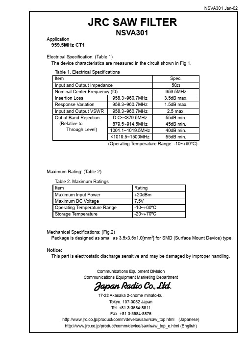
Note 1. This specification specifies the quality of this component as a single unit. Make sure that this component is evaluated and confirmed against this specification when it is mounted to your products.
Mechanical Specifications: (Fig.2) Package is designed as small as 3.5x3.5x1.0[mm3] for SMD (Surface Mount Device) type. Notice: This part is electrostatic discharge sensitive and may be damaged by improper handling.
Communications Equipment Division Communications Equipment Marketing Department
17-22 Akasaka 2-chome minato-ku, Tokyo. 107-0052 Japan Tel. +81 3-3584-8811 Fax. +81 3-3584-8876 http://www.jrc.co.jp/product/comm/deveice/saw/saw_top.html (Japanese) http://www.jrc.co.jp/product/comm/device/saw/saw_top_e.html (English)
NSVA301 Jan-02
IN 50Ω
ZWS240PAF-24S中文资料(DENSEI-LAMBDA)中文数据手册「EasyDatasheet - 矽搜」

2 year warranty
型号名称
ZWS 100AF-5/
Series Name
Option
Output Power
Active Filter contained
Output Voltage
特征
marking (Low Voltage Directive) Active Filter contained, PFHC type Applicable to peakoutput wattage 120% (12V, 15V, 24V output) Low leakage current 0.5mA max Equipped with Remote ON/OFF control (with-cover type excluded) and output variable voltage 2 year warranty
产品阵容
Model name ZWS50AF ZWS75AF ZWS100AF ZWS150AF
ZWS50AF-5 ZWS50AF-12 ZWS50AF-15 ZWS50AF-24 ZWS75AF-5
ZWS75AF-12 ZWS75AF-15 ZWS75AF-24 ZWS100AF-5 ZWS100AF-12 ZWS100AF-15
芯片中文手册,看全文,戳
ZWS-AF -系列
单路输出50W〜150W
(Low Voltage Directive)
技术指标
1.输 入 电 压 范 围 2.功 率 因 数 3,输 出 电 压 范 围 4.冷 却 5.工 作 环 境
温度 (标准安装)
6.耐 压 7.安 全 标 准 8. CE标志 9. EMI 10.免 疫 11. PFHC 12.函 数
MR系统

4. RF线圈的种类
• 以成像中起的作用分:
– 发射线圈 – 接收线圈
• 发射线圈、接收线圈共用:
– 体线圈 – 头线圈 – 四肢线圈
• 表面线圈仅用于接收
四. 系统调节
• 进入磁体孔腔的物体影响磁场均匀性分布, 同时使线圈的填充系数发生变化,影响线 圈的阻抗特性和品质因数,每次检查病人 前需要进行校准。
2 涡流
• 根据楞次定律,变化的磁场在周围导电材料 中感应随时间变化的电流——涡流。 • 涡流本身又产生随时间变化的磁场,消弱梯 度场,破坏了梯度场就破坏了编码。 • 涡流补偿
– 利用RC元件使电流脉冲预畸变 – 预先补偿梯度的驱动电流 – 有源梯度屏蔽
高性能梯度系统
高切换率 线性、非线性梯度系统、双梯度系统 消噪技术 无源噪声控制 有源噪声控制 真空消噪技术
1 励磁过程 A. 冷却磁体:主磁体线圈处于超导状 态; B. 线圈加载:注入电流 2 退磁
3.失超( Quench
)
• 超导线圈的部分不再是超导状态,线圈储存 的能量部分变成热能散出; • 热能使得线圈的其他部分加热继而失去超导 状态产生更过的热量,恶性循环直至遍及整 个磁体发生失超。 • 失超原因: – 磁通跳跃(Flux jump)~释放能量 – 摩擦生热(Friction resulting heat)~线圈 的微小运动
2.有源匀场(Actively shimming) • 一系列载流绕组排列在磁体孔径的柱形管上, 每个绕组产生的校正磁场与球形谐波展开式 的一个系数近似,设计这些绕组时必须避免 它们与磁体和梯度线圈的相互影响; • 线圈中的电流在系统安装期间确定并保持不 变,直到有工程师进行再匀场时才改变; • 有源匀场使用的线圈绕组有三类:超导匀场 线圈、常导匀场线圈和梯度线圈
Omega HHM-301 300 Amp Flex Clamp Adapter 说明书

HHM-301300 Amp Flex Clamp Adapter e-mail:**************For latest product manuals: Shop online at SM User’s Guide***********************Servicing North America:U.S.A.:Omega Engineering, Inc., One Omega Drive, P.O. Box 4047 S tamford, CT 06907-0047 USAToll-Free: 1-800-826-6342 (USA & Canada only)Customer Service: 1-800-622-2378 (USA & Canada only)Engineering Service: 1-800-872-9436 (USA & Canada only)Tel: (203) 359-1660 Fax: (203) 359-7700e-mail:**************For Other Locations Visit /worldwideThe information contained in this document is believed to be correct, but OMEGA accepts no liability for any errors it contains, and reserves the right to alter specifications without notice.TABLE OF CONTENTSIntroduction. . . . . . . . . . . . . . . . . . . . . . . . . . . . . . . . . . . . . . 2 –3Key Features. . . . . . . . . . . . . . . . . . . . . . . . . . . . . . . . . . . . . . . . 3What’s in the Box . . . . . . . . . . . . . . . . . . . . . . . . . . . . . . . . . . . . 3Product Overview. . . . . . . . . . . . . . . . . . . . . . . . . . . . . . . . . . . . 4Safety Instructions. . . . . . . . . . . . . . . . . . . . . . . . . . . . . . . . 4 –5Setup Instructions. . . . . . . . . . . . . . . . . . . . . . . . . . . . . . . . . . . . 5Install Batteries . . . . . . . . . . . . . . . . . . . . . . . . . . . . . . . . . . . . 5Operating Instructions. . . . . . . . . . . . . . . . . . . . . . . . . . . . . 5 –7Specifications . . . . . . . . . . . . . . . . . . . . . . . . . . . . . . . . . . . . . . . 8Operating & Maintenance Tips . . . . . . . . . . . . . . . . . . . . . . . . . . 9 INTRODUCTIONThank you for purchasing the HHM301 Flex Clamp Adapter. Please read this user’s manual carefully and thoroughly before using the instrument.The HHM301 enables any clamp meter or multimeter to enclose a thick or hard- to-reach conductor, bundle of conductors, or busbar while increasing its AC current measurement range to up to 3000 Amperes.The product has three components: a flexible probe, a current-to-voltage converter, and a pair of banana plug output leads. When formed into a loop, the probe is called a Rogowski coil. A Rogowski coil is a helical coil of wire inside a shield that is designed to be placed around a straight conductor, a bundle of conductors, or a copper busbar that typically carries large currents (>10A). The voltage induced in a Rogowski coil is proportional to the rate of change (derivative) of current in the straight conductor. In the HHM301, the integrator circuit needed to change the output of the Rogowski coil to a voltage signal proportional to current is located inside the current-to-voltage converter.2The converter allows the electrician to choose the HHM301’s full-scale current’s range and therefore its current-to-voltage conversion factor. The rotary switch on the converter has three positions: 30A, 300A and 3000A. With the switch in the 30A position, the unit converts current to voltage at a ratio of 100mV/A and outputs the result to the banana plug output leads. The leads are designed to be plugged into a multimeter or clamp meter operating in AC voltage measurement mode. The electrician can then use a simple formula to convert the meter’s voltage reading back to a current measurement.With the converter switch in the 300A position, the conversion factor changeto 10mV/A; in the 3000A position, the conversion factor is 1mV/A. The three ranges offer the electrician three options for measuring very large currents each with a unique combination of range and resolution.The converter is powered by 2 “AAA” batteries, which are supplied with the instrument.KEY FEATURES• Three full-scale ranges: 0 to 3000A, 0 to 300A, 0 to 30A• 18 in. (458mm) long probe creates 6 in. diameter loop• Measurements accurate within 1% of full-scale range• Probe is safe for CAT III 1000V, CAT IV 600V use, converter is safe forCAT II 1000V, CAT III 600V use• Powered by 2 “AAA”batteries (included)WHAT’S IN THE BOXThe HHM301 (a converter plus a non-detachable probe plus non-detachable 90°banana plug output leads) comes fully assembled in a box along with 2 “AAA” batteries and this user’s manual.3PRODUCTOVERVIEWFig. 1 shows the labels andpositions of the controls,indicators and physicalstructures of the HHM301.Familiarize yourself with thefunctions and meanings ofthese controls, indicators andstructures before moving onto the Setup Instructions andOperating Instructions.Flexible current probe(Rogowski coil)Probe couplingPower/Range rotary switchBanana plug output leadsGreen (power on) LEDRed (low battery) LEDBattery compartmentCurrent-to-voltage converterSAFETY INSTRUCTIONSWarning• Do not operate the HHM301 if the probe, converter or test leads appear to be damaged.• When measuring bare conductors, use appropriate personal protective equipment (PPE) such as rubber gloves and headgear certified for high-voltage work.• Also wear PPE if any circuits in the system remain “live” during themeasurement.• If the magnitude of the current to be measured is unknown, set theconverter’s range switch to the highest (3000A) position to begin testing. 4• Always de-energize the circuit under test before installing the flexibleprobe.• Exercise extreme caution when measuring voltages greater than 60VDC or 30VAC.• Never use the probe on a circuit with voltages higher than CAT III 600V.• Never operate the HHM301 with the converter's battery compartmentdoor open.SETUP INSTRUCTIONSINSTALL BATTERIESWarningBefore changing batteries, move the flexible probe away from any live circuits and set the converter switch to the OFF position.The HHM301’s battery compartment (Fig. 1, Callout 7) is located at the back of the converter. To open the compartment, use a small Phillips-head screwdriver to remove the single screw securing the battery compartment cover. Be careful not to lose the small screw. Put the screw and the cover to the side.Install the two supplied “AAA” batteries in the compartment, using the polarity marks stenciled inside it as a guide. Replace the battery compartment cover and secure it with the Phillips-head screw. OPERATING INSTRUCTIONS1.Power on the HHM301 by turning the converter’s rotary switch from the OFF position to the appropriate Range position: 30A, 300A or 3000A. The green LED on the left side of the front panel (Fig. 1, Callout 5) will illuminate. If the magnitude of the current to be measured is unknown, initially set the switch to the 3000A position. You can switch to a narrower range later to improve your measurement resolution if the magnitude of measured current is low enough to warrant doing so.2. Plug the banana plugs into the test jacks of your multimeter or clamp meter, taking care to observe + (positive/red) and – (negative or common/black) polarity markings.3. On your multimeter or clamp meter, select AC voltage measuremen in Auto Ranging mode, or a full-scale range of 3 to 10V in Manual Ranging mode.54. Pull the end of the probe closest to the mark on the probe coupling (Fig. 1, Callout 2) out of the coupling, enclose the conductor(s) or busbar whose current you wish to measure, and then plug the end of the probe back into the coupling (see figure below).position the conductor(s) as close to the center of the loop as possible, given physical limitations. Measurement accuracy decreases by 1% for each 1 in. of positioning off-center.6. Read the measured voltage on your multimeter or clamp meter. If you are using an Auto Ranging meter, the meter will automatically provide readings with the highest resolution. If you are using Manual Ranging, begin by selecting the meter's widest full-scale AC voltage range. Then try switching to a narrower range to improve your measurement resolution.7. Calculate the measured current from the displayed voltage reading using the following formula:Actual current = Voltage reading ÷ Conversion ratioThe conversion ratio for each of the three HHM301 measurement ranges is stenciled on the converter at the left of the range label. The ratios for the 3000A, 300A and 30A ranges are 1mV/A, 10mV/A, and 100mV/A, respectively.6As an example, consider an application in which your multimeter reads 3VAC with input from the HHM301 operating in the 30A range (see figure below).The conversion factor for the 3A range is 100mV/A. Inserting these values into the formula yields the following result:Actual current = Voltage reading ÷ Conversion ratioX= 3V÷100mV/AActual current =30A7SPECIFICATIONS• Measurement Ranges: 0 to 3000A (full-scale), 0 to 300A, 0 to 30A• Conversion Ratios: 1mV/A in 3000A range; 10mV/A in 300A range; 100mV/A in 30A range• Measurement Accuracy: ±1% of full-scale value• Position Error: ±1% @ 1 in. from conductor; ±2% @ 2 in.; ±3% @ 3 in.• Safety Ratings: CAT III 1000V, CAT IV 600V (probe); CAT II 1000V, CAT III 600V (controller)• Probe Length: 18 in. (458mm); creates 6 in. diameter loop• Probe Diameter: 0.33 in. (8.5mm)• Cable Length (probe to converter): 6 ft. (1.8m)• Bandwidth (-3dB): 10Hz to 10kHz• Output Impedance: 10kΩ, minimum• Operating Temperature: 32° to 122°F (0° to 50°C) @ <80%RH• Dimensions of Converter: 4.7 x 2.8 x 1.0 in. (120 x 70 x 26mm)• Weight (including batteries): 11.4 oz. (325g)• Power Source: (2) “AAA” batteries (included)8OPERATING & MAINTENANCE TIPSWhen the red LED on the right side of the converter’s front panel (Fig. 1, Callout 6) illuminates, it’s time to replace the two “AAA” batteries that power the unit (although measurements will remain valid for several hours after the light appears). To replace the batteries, follow the instructions on p. 5. A fresh pair of batteries should typically power 120 hours of operation.The HHM301 is not equipped with an Auto Power Off circuit. To avoid draining the batteries, remember to set the converter’s rotary switch to the OFF position after each measurement session.Remove the batteries when storing the unit or when you do not expect to use it for a long time (months rather than weeks).Do not operate the HHM301 in the presence of a flammable or explosive gas or near an arc welder or induction heater.After subjecting the instrument to a large change in ambient temperature, wait at least 30 minutes before making measurements to guarantee the accuracy of readings.Do not disassemble the HHM301 or immerse it in water.Make sure that the probe, converter and test leads are clean, dry and free of surface contamination before using the instrument.9FOR WARRANTY RETURNS, please have the following information available BEFORE contacting OMEGA:1. P urchase Order number under which the product was PURCHASED,2. M odel and serial number of the product under warranty, and 3. R epair instructions and/or specific problems relative to the product.FOR NON-WARRANTY REPAIRS, consult OMEGA for current repair charges. Have the following information available BEFORE contacting OMEGA:1. Purchase Order number to cover the COST of the repair,2. M odel and serial number of the product, and3. R epair instructions and/or specific problems relative to the product.OMEGA’s policy is to make running changes, not model changes, whenever an improvement is possible. This affords our customers the latest in technology and engineering.OMEGA is a registered trademark of OMEGA ENGINEERING, INC.© Copyright 2016 OMEGA ENGINEERING, INC. All rights reserved. T his document may not be copied, photocopied, reproduced, translated, or reduced to any electronic medium or machine-readable form, in whole or in part, without the prior written consent of OMEGA ENGINEERING, INC.WARRANTY/DISCLAIMEROMEGA ENGINEERING, INC. warrants this unit to be free of defects in materials and workmanship for a period of 13 months from date of purchase. OMEGA’s Warranty adds an additional one (1) month grace period to the normal one (1) year product warranty to cover handling and shipping time. T his ensures that OMEGA’s customers receive maximum coverage on each product.If the unit malfunctions, it must be returned to the factory for evaluation. OMEGA’s Customer Service Department will issue an Authorized Return (AR) number immediately upon phone or written request. Upon examination by OMEGA, if the unit is found to be defective, it will be repaired or replaced at no charge. OMEGA’s WARRANT Y does not apply to defects resulting from any action of the purchaser, including but not limited to mishandling, improper interfacing, operation outside of design limits, improper repair, or unauthorized modification. T his WARRANTY is VOID if the unit shows evidence of having been tampered with or shows evidence of having been damaged as a result of excessive corrosion; or current, heat, moisture or vibration; improper specification; misapplication; misuse or other operating conditions outside of OMEGA’s control. Components in which wear is not warranted, include but are not limited to contact points, fuses, and triacs.OMEGA is pleased to offer suggestions on the use of its various products. However, OMEGA neither assumes responsibility for any omissions or errors nor assumes liability for any damages that result from the use of its products in accordance with information provided by OMEGA, either verbal or written. OMEGA warrants only that the parts manufactured by the company will be as specified and free of defects. OMEGA MAKES NO OTHER W ARRANTIES OR REPRESENTATIONS OF ANY KIND W HATSOEVER, EXPRESSED OR IMPLIED, EXCEPT THAT OF TITLE, AND ALL IMPLIED W ARRANTIES INCLUDING ANY W ARRANTY OF MERCHANTABILITY AND FITNESS FOR A PARTICULAR PURPOSE ARE HEREBY DISCLAIMED. LIMITATION OF LIABILITY: The remedies of purchaser set forth herein are exclusive, and the total liability of OMEGA with respect to this order, whether based on contract, warranty, negligence, indemnification, strict liability or otherwise, shall not exceed the purchase price of the component upon which liability is based. In no event shall OMEGA be liable for consequential, incidental or special damages.CONDITIONS: Equipment sold by OMEGA is not intended to be used, nor shall it be used: (1) as a “Basic Component” under 10 CFR 21 (NRC), used in or with any nuclear installation or activity; or (2) in medical applications or used on humans. Should any Product(s) be used in or with any nuclear installation or activity, medical application, used on humans, or misused in any way, OMEGA assumes no responsibility as set forth in our basic WARRANT Y/DISCLAIMER language, and, additionally, purchaser will indemnify OMEGA and hold OMEGA harmless from any liabilityor damage whatsoever arising out of the use of the Product(s) in such a manner.RETURN REQUESTS/INQUIRIESDirect all warranty and repair requests/inquiries to the OMEGA Customer Service Department. BEFORE RET URNING ANY PRODUCT (S) T O OMEGA, PURCHASER MUST OBT AIN AN AUT HORIZED RET URN (AR) NUMBER FROM OMEGA’S CUST OMER SERVICE DEPART MENT (IN ORDER T O AVOID PROCESSING DELAYS). T he assigned AR number should then be marked on the outside of the return package and on any correspondence. The purchaser is responsible for ship-ping charges, freight, insurance and proper packaging to prevent breakage in transit.Where Do I Find Everything I Need for Process Measurement and Control?OMEGA…Of Course!Shop online at SMTEMPERATUREM U T hermocouple, RTD & Thermistor Probes, Connectors, Panels &AssembliesM U W ire: Thermocouple, RTD &ThermistorM U C alibrators & Ice Point References M U R ecorders, Controllers & Process MonitorsM U I nfrared Pyrometers PRESSURE, STRAIN AND FORCEM U Transducers & Strain GagesM U Load Cells & Pressure GagesM U Displacement TransducersM U Instrumentation & Accessories FLOW/LEVELM U R otameters, Gas Mass Flowmeters & Flow ComputersM U Air Velocity IndicatorsM U Turbine/Paddlewheel SystemsM U Totalizers & Batch ControllerspH/CONDUCTIVITYM U p H Electrodes, Testers &AccessoriesM U Benchtop/Laboratory MetersM U C ontrollers, Calibrators, Simulators & PumpsM U I ndustrial pH & Conductivity Equipment DATA ACQUISITIONM U D ata Acquisition & Engineering SoftwareM U C ommunications-Based Acquisition SystemsM U P lug-in Cards for Apple, IBM & CompatiblesM U Data Logging SystemsM U Recorders, Printers & Plotters HEATERSM U Heating CableM U Cartridge & Strip HeatersM U Immersion & Band HeatersM U Flexible HeatersM U Laboratory Heaters ENVIRONMENTAL MONITORING AND CONTROL M U M etering & ControlInstrumentationM U RefractometersM U Pumps & TubingM U Air, Soil & Water MonitorsM U I ndustrial Water & Wastewater TreatmentM U p H, Conductivity & Dissolved Oxygen InstrumentsM5563/0516。
核磁共振主机磁体系统硬件参数配置
核磁共振主机磁体系统硬件参数配置一、磁体系统产生强大,均匀的,稳定的静磁场,用于组织的磁化。
1.1、1.5超导磁体1,通电螺线管感生的磁场强度,与螺线管的匝数,通过的电流大小成正比。
根据焦耳定律,电流通过导体产生的热量,跟电流的平方成正比,跟导体电阻成正比。
如果用普通导体来产生磁场,所消耗的能量将十分巨大。
而超导现象中的零电阻效应,正好解决了线圈发热的问题。
在超导体中的大电流,能够长久运行,而不会转变成热量。
为了实现超导环境,就必须达到超低温。
目前的超导磁共振都是使用液氦来实现的,是目前超导的基础。
2,低温超导金属NbTi(铌钛)合金优良的超导电性和加工性能,其Tc 为9.3K,其使用已占低温超导合金的95%左右。
NbTi 合金可用多芯复合加工法加工成以铜(或铝)为基体的多芯复合NbTi/Cu(铌-钛与铜)超导线材(其Tc为4.2K,即-268.80C),可用于制造MRI 设备的超导磁体。
3,超导磁体首要由超导螺线管线圈(略称超导线圈)、高真空超低温杜瓦容器、和附属器件构成。
1.2、状态监控系统磁体线圈温度、应力、液氦液位、真空度、流量、杜瓦容器压力等参数值的变化。
1.3、紧急处置装置标记: 见场地要求1.4、氦气排放系统标记: 见场地要求1,失超管汇集了磁体的所有气体挥发管口,从磁体上端直通磁体间建筑外大气中。
平时,掉超管的作用就是排除废气。
一旦失超,磁体杜瓦容器中液氦挥发的全部氦气(每一升液氦可气化为1.25m3氦气)将从管中喷出。
如果掉超管预设尺寸不足、铺设路径不合理、欠亨畅、甚至堵塞,磁体因内部压力快速增高而被损坏的可能性将增大。
1.5、磁体外壳1.6、4K冷头,零液氦消耗技术1,绝对温度0K=-273℃,液氦沸点为-268.785 ℃;2,4K冷头+磁体:液氦温度4.2K=-268.8 ℃,可保证液氦不挥发;3,氦气最主要的来源不是空气,而是天然气。
原来氦气在干燥空气中含量极微,平均只有百万分之五,天然气中最高则可含7.5%的氦,是空气的一万五千倍。
MR系列产品说明书

深圳市迅博信息技术有限公司MR系列产品说明书注:因产品型号不同,不同产品之间可能存在差异目录一、MR系列产品介绍 (4)二、产品快速使用指南 (4)三、详细配置说明 (4)1.运行状态 (4)运行状态--->系统信息 (4)运行状态--->在线主机列表 (5)运行状态--->系统日志 (6)2. 设备流量状态 (6)设备流量状态--->实时流量 (6)3.测试工具 (7)测试工具--->Ping (7)测试工具--->Trace (8)测试工具--->网络唤醒 (9)4.网络设置 (10)网络设置-->网络设置 (10)基本设置-->路由时间 (12)基本设置-->动态域名 (12)基本设置-->静态DHCP (13)5.高级设置 (14)高级设置-->高级网络设置 (14)高级设置--->DHCP / DNS (16)高级设置--->防火墙 (17)高级设置--->路由MAC设置 (18)高级设置--->路由表设置 (18)6.转发规则 (19)转发规则---> 虚拟服务 (19)转发规则---> DMZ主机 (19)转发规则---> 端口转发 (20)转发规则---> UpnP/NAT-PMP (20)7.智能QOS (20)智能QOS--->基本设置 (20)智能QOS--->宽带分类 (22)智能QOS--->视图模式 (23)智能QOS--->详细信息 (24)8.IP/MAC速度限制 (24)IP/MAC速度限制--->IP限速 (24)IP/MAC速度限制--->ARP绑定 (25)9.VPN设置 (25)VPN设置--->服务器 (25)VPN设置--->客户端 (28)10.VPN软件客户端 (30)VPN软件客户端--->VPN软件安装 (30)VPN软件客户端--->VPN软件参数配置 (33)VPN软件客户端--->VPN无法连接时的备用寻址 (35)VPN软件客户端--->VPN软件开机自启动设置 (36)11.系统管理 (37)系统管理--->登录管理 (37)系统管理--->带宽监控 (38)系统管理--->设置管理 (39)系统管理--->定时任务 (39)系统管理--->升级固件 (40)一、M R系列产品介绍MR系列产品最大的亮点是解决了VPN应用中的动态域名寻域不稳定的难题,采用WEB智能目录服务很好的解决了VPN服务器端IP地址变化的问题;该系列有MR1300、MR-2600、MR5100等型号产品,产品功能主要包括如下几个方面:VPN异地局域网互连双VPN服务器QOS/IP限速,合理分配网络带宽设备流量实时查看,了解电脑流量状况ARP绑定,阻止非法用户使用网络IP/MAC速度限制这些都是企业所迫切需要的非常实用的功能,一台设备可以解决客户所有的网络管理需求,在解决用户VPN连接的问题外,设备本身还附带有企业常用的上网行为管理功能,是性价比非常高的产品。
MR专用生理门控系统简介

4、使用环境
1.环境温度范围:10℃~35℃ 相对湿度:20%~70% 大气压力: 86kPa~106kPa 电源电压: a.c.220V±22V 电源频率: 50Hz±1Hz
指脉检测盒
门控信号触发 输出指示灯
电源指示灯
信号检测盒开 关
信号检测盒开 关
电源指示灯
门控信号触发 输出指示灯
心电检测盒
信号检测盒开 关
电源指示灯
门控信号触发 输出指示灯
USB-网口信号转换盒 光纤电缆:灰色端连接在检测盒上,蓝色端连接在门控信号处理盒上。 USB 电缆:一端连接 USB-网口信号转换盒的 USB 接口,另一端连接电脑主机 USB
2.3.4 心电门控 将心电信号检测器通过电极片与被试者连接。电极片连接位置如下图所示:
正电极(红色):左腋前线第 6 肋间处; 负电极(白色):胸骨左缘第 3 肋间处,与乳头、正电极在同一直线上; 参考电极(黑色):胸骨下或稍偏左位置。 将光纤接收灰色插头接入心电检测盒顶部的光纤插座上。 长按信号检测盒上的开关键 3 秒,电源指示灯显示绿色,心电检测盒上电。电源指示灯 显示红色时代表信号检测盒电量不足,请充电后使用。此时,门控信号处理盒上相应的 门控输入指示灯亮。 指脉触发:信号检测盒上的门控信号触发输出指示灯和生理门控信号处理盒上的门控输 出指示灯随着被试者的心搏点亮,生理门控信号处理盒上相应的门控选择指示灯长亮, 信号正常传输。 关机:使用完成后,长按信号检测盒上的开关键 3 秒,电源指示灯灭,呼吸检测盒关机。 此时,门控信号处理盒上相应的门控输入指示灯灭。
MAX系列芯片速查

MAXIM/DALLAS 中文数据资料DS12CR887, DS12R885, DS12R887 RTC,带有恒压涓流充电器DS1870 LDMOS RF功放偏置控制器DS1921L-F5X Thermochron iButtonDS1923 温度/湿度记录仪iButton,具有8kB数据记录存储器DS1982, DS1982-F3, DS1982-F5 1k位只添加iButton?DS1990A 序列号iButtonDS1990R, DS1990R-F3, DS1990R-F5 序列号iButtonDS1991 多密钥iButtonDS2129 LVD SCSI 27线调节器DS2401 硅序列号DS2406 双通道、可编址开关与1k位存储器DS2408 1-Wire、8通道、可编址开关DS2411 硅序列号,带有VCC输入DS2413 1-Wire双通道、可编址开关DS2430A 256位1-Wire EEPROMDS2431 1024位、1-Wire EEPROMDS2480B 串行、1-Wire线驱动器,带有负荷检测DS2482-100 单通道1-Wire主控制器DS2482-100 勘误表PDF: 2482-100A2DS2482-800, DS2482S-800 八通道1-Wire主控制器DS2482-800 勘误表PDF: 2482-800A2DS2502 1k位只添加存储器DS2505 16k位只添加存储器DS28E04-100 4096位、可寻址、1-Wire EEPROM,带有PIO DS3170DK DS3/E3单芯片收发器开发板DS3231, DS3231S 高精度、I2C集成RTC/TCXO/晶振DS33Z44 四路以太网映射器DS3902 双路、非易失、可变电阻器,带有用户EEPROMDS3906 三路、非易失、小步长调节可变电阻与存储器DS3984 4路冷阴极荧光灯控制器DS4302 2线、5位DAC,提供三路数字输出DS80C400-KIT DS80C400评估套件DS80C410, DS80C411 具有以太网和CAN接口的网络微控制器DS80C410 勘误表PDF: 80C410A1DS89C430, DS89C440, DS89C450 超高速闪存微控制器DS89C430 勘误表PDF: 89C430A2DS89C440 勘误表PDF: 89C440A2DS89C450 勘误表PDF: 89C450A2DS89C430 勘误表PDF: 89C430A3DS89C440 勘误表PDF: 89C440A3DS89C450 勘误表PDF: 89C450A3DS89C430 勘误表PDF: 89C430A5DS89C440 勘误表PDF: 89C440A5DS89C450 勘误表PDF: 89C450A5DS9090K 1-Wire器件评估板, B版DS9097U-009, DS9097U-E25, DS9097U-S09 通用1-Wire COM端口适配器DS9490, DS9490B, DS9490R USB至1-Wire/iButton适配器MAX1034, MAX1035 8/4通道、±VREF多量程输入、串行14位ADCMAX1072, MAX1075 1.8Msps、单电源、低功耗、真差分、10位ADCMAX1076, MAX1078 1.8Msps、单电源供电、低功耗、真差分、10位ADC,内置电压基准MAX1146, MAX1147, MAX1148, MAX1149 多通道、真差分、串行、14位ADC MAX1149EVKIT MAX1149评估板/评估系统MAX1220, MAX1257, MAX1258 12位、多通道ADC/DAC,带有FIFO、温度传感器和GPIO端口MAX1224, MAX1225 1.5Msps、单电源、低功耗、真差分、12位ADCMAX1258EVKIT MAX1057, MAX1058, MAX1257, MAX1258评估板/评估系统MAX1274, MAX1275 1.8Msps、单电源、低功耗、真差分、12位ADCMAX13000E, MAX13001E, MAX13002E, MAX13003E, MAX13004E, MAX13005E 超低电压电平转换器MAX1302, MAX1303 8/4通道、±VREF多量程输入、串行16位ADCMAX1304, MAX1305, MAX1306, MAX1308, MAX1309, MAX1310, MAX1312, MAX1313, MAX1314 8/4/2通道、12位、同时采样ADC,提供±10V、±5V或0至+5V 模拟输入范围MAX13050, MAX13052, MAX13053, MAX13054 工业标准高速CAN收发器,具有±80V故障保护MAX13080E, MAX13081E, MAX13082E, MAX13083E, MAX13084E, MAX13085E, MAX13086E, MAX13087E, MAX13088E, MAX13089E +5.0V、±15kV ESD保护、失效保护、热插拔、RS-485/RS-422收发器MAX13101E, MAX13102E, MAX13103E, MAX13108E 16通道、带有缓冲的CMOS 逻辑电平转换器MAX1334, MAX1335 4.5Msps/4Msps、5V/3V、双通道、真差分10位ADCMAX1336, MAX1337 6.5Msps/5.5Msps、5V/3V、双通道、真差分8位ADCMAX13481E, MAX13482E, MAX13483E ±15kV ESD保护USB收发器, 外部/内部上拉电阻MAX1350, MAX1351, MAX1352, MAX1353, MAX1354, MAX1355, MAX1356, MAX1357 双路、高端、电流检测放大器和驱动放大器MAX1450 低成本、1%精确度信号调理器,用于压阻式传感器MAX1452 低成本、精密的传感器信号调理器MAX1487, MAX481, MAX483, MAX485, MAX487, MAX488, MAX489, MAX490, MAX491 低功耗、限摆率、RS-485/RS-422收发器MAX1492, MAX1494 3位半和4位半、单片ADC,带有LCD驱动器MAX1494EVKIT MAX1493, MAX1494, MAX1495评估板/评估系统MAX1497, MAX1499 3位半和4位半、单片ADC,带有LED驱动器和μC接口MAX1499EVKIT MAX1499评估板/评估系统MAX15000, MAX15001 电流模式PWM控制器, 可调节开关频率MAX1515 低电压、内置开关、降压/DDR调节器MAX1518B TFT-LCD DC-DC转换器, 带有运算放大器MAX1533, MAX1537 高效率、5路输出、主电源控制器,用于笔记本电脑MAX1533EVKIT MAX1533评估板MAX1540A, MAX1541 双路降压型控制器,带有电感饱和保护、动态输出和线性稳压器MAX1540EVKIT MAX1540评估板MAX1551, MAX1555 SOT23、双输入、USB/AC适配器、单节Li+电池充电器MAX1553, MAX1554 高效率、40V、升压变换器,用于2至10个白光LED驱动MAX1556, MAX1557 16μA IQ、1.2A PWM降压型DC-DC转换器MAX1556EVKIT MAX1556EVKIT评估板MAX1558, MAX1558H 双路、3mm x 3mm、1.2A/可编程电流USB开关,带有自动复位功能MAX1586A, MAX1586B, MAX1586C, MAX1587A, MAX1587C 高效率、低IQ、带有动态内核的PMIC,用于PDA和智能电话MAX16801A/B, MAX16802A/B 离线式、DC-DC PWM控制器, 用于高亮度LED驱动器MAX1858A, MAX1875A, MAX1876A 双路180°异相工作的降压控制器,具有排序/预偏置启动和PORMAX1870A 升/降压Li+电池充电器MAX1870AEVKIT MAX1870A评估板MAX1874 双路输入、USB/AC适配器、1节Li+充电器,带OVP与温度调节MAX1954A 低成本、电流模式PWM降压控制器,带有折返式限流MAX1954AEVKIT MAX1954A评估板MAX19700 7.5Msps、超低功耗模拟前端MAX19700EVKIT MAX19700评估板/评估系统MAX19705 10位、7.5Msps、超低功耗模拟前端MAX19706 10位、22Msps、超低功耗模拟前端MAX19707 10位、45Msps、超低功耗模拟前端MAX19708 10位、11Msps、超低功耗模拟前端MAX2041 高线性度、1700MHz至3000MHz上变频/下变频混频器,带有LO缓冲器/开关MAX2043 1700MHz至3000MHz高线性度、低LO泄漏、基站Rx/Tx混频器MAX220, MAX222, MAX223, MAX225, MAX230, MAX231, MAX232, MAX232A, MAX233, MAX233A, MAX234, MAX235, MAX236, MAX237, MAX238, MAX239, MAX240, MAX241, MAX242, MAX243, MAX244, MAX245, MAX246, MAX247, MAX248, MAX249 +5V供电、多通道RS-232驱动器/接收器MAX2335 450MHz CDMA/OFDM LNA/混频器MAX2370 完备的、450MHz正交发送器MAX2370EVKIT MAX2370评估板MAX2980 电力线通信模拟前端收发器MAX2986 集成电力线数字收发器MAX3013 +1.2V至+3.6V、0.1μA、100Mbps、8路电平转换器MAX3205E, MAX3207E, MAX3208E 双路、四路、六路高速差分ESD保护ICMAX3301E, MAX3302E USB On-the-Go收发器与电荷泵MAX3344E, MAX3345E ±15kV ESD保护、USB收发器,UCSP封装,带有USB检测MAX3394E, MAX3395E, MAX3396E ±15kV ESD保护、大电流驱动、双/四/八通道电平转换器, 带有加速电路MAX3535E, MXL1535E +3V至+5V、提供2500VRMS隔离的RS-485/RS-422收发器,带有±15kV ESD保护MAX3570, MAX3571, MAX3573 HI-IF单芯片宽带调谐器MAX3643EVKIT MAX3643评估板MAX3645 +2.97V至+5.5V、125Mbps至200Mbps限幅放大器,带有信号丢失检测器MAX3654 47MHz至870MHz模拟CATV互阻放大器MAX3654EVKIT MAX3654评估板MAX3657 155Mbps低噪声互阻放大器MAX3658 622Mbps、低噪声、高增益互阻前置放大器MAX3735, MAX3735A 2.7Gbps、低功耗、SFP激光驱动器MAX3737 多速率激光驱动器,带有消光比控制MAX3737EVKIT MAX3737评估板MAX3738 155Mbps至2.7Gbps SFF/SFP激光驱动器,带有消光比控制MAX3744, MAX3745 2.7Gbps SFP互阻放大器,带有RSSIMAX3744EVKIT, MAX3745EVKIT MAX3744, MAX3745评估板MAX3748, MAX3748A, MAX3748B 紧凑的、155Mbps至4.25Gbps限幅放大器MAX3785 6.25Gbps、1.8V PC板均衡器MAX3787EVKIT MAX3787评估板MAX3793 1Gbps至4.25Gbps多速率互阻放大器,具有光电流监视器MAX3793EVKIT MAX3793评估板MAX3805 10.7Gbps自适应接收均衡器MAX3805EVKIT MAX3805评估板MAX3840 +3.3V、2.7Gbps双路2 x 2交叉点开关MAX3841 12.5Gbps CML 2 x 2交叉点开关MAX3967 270Mbps SFP LED驱动器MAX3969 200Mbps SFP限幅放大器MAX3969EVKIT MAX3969评估板MAX3982 SFP铜缆预加重驱动器MAX3983 四路铜缆信号调理器MAX3983EVKIT MAX3983评估板MAX3983SMAEVKIT MAX3983 SMA连接器评估板MAX4079 完备的音频/视频后端方案MAX4210, MAX4211 高端功率、电流监视器MAX4210EEVKIT MAX4210E、MAX4210A/B/C/D/F评估板MAX4211EEVKIT MAX4211A/B/C/D/E/F评估板MAX4397 用于双SCART连接器的音频/视频开关MAX4397EVKIT MAX4397评估系统/评估板MAX4411EVKIT MAX4411评估板MAX4729, MAX4730 低电压、3.5、SPDT、CMOS模拟开关MAX4754, MAX4755, MAX4756 0.5、四路SPDT开关,UCSP/QFN封装MAX4758, MAX4759 四路DPDT音频/数据开关,UCSP/QFN封装MAX4760, MAX4761 宽带、四路DPDT开关MAX4766 0.075A至1.5A、可编程限流开关MAX4772, MAX4773 200mA/500mA可选的限流开关MAX4795, MAX4796, MAX4797, MAX4798 450mA/500mA限流开关MAX4826, MAX4827, MAX4828, MAX4829, MAX4830, MAX4831 50mA/100mA 限流开关, 带有空载标记, μDFN封装MAX4832, MAX4833 100mA LDO,带有限流开关MAX4834, MAX4835 250mA LDO,带有限流开关MAX4836, MAX4837 500mA LDO,带有限流开关MAX4838A, MAX4840A, MAX4842A 过压保护控制器,带有状态指示FLAGMAX4850, MAX4850H, MAX4852, MAX4852H 双路SPDT模拟开关,可处理超摆幅信号MAX4851, MAX4851H, MAX4853, MAX4853H 3.5/7四路SPST模拟开关,可处理超摆幅信号MAX4854 7四路SPST模拟开关,可处理超摆幅信号MAX4854H, MAX4854HL 四路SPST、宽带、信号线保护开关MAX4855 0.75、双路SPDT音频开关,具有集成比较器MAX4864L, MAX4865L, MAX4866L, MAX4867, MAX4865, MAX4866 过压保护控制器,具有反向保护功能MAX4880 过压保护控制器, 内置断路开关MAX4881, MAX4882, MAX4883, MAX4884 过压保护控制器, 内部限流, TDFN封装MAX4901, MAX4902, MAX4903, MAX4904, MAX4905 低RON、双路SPST/单路SPDT、无杂音切换开关, 可处理负电压MAX4906, MAX4906F, MAX4907, MAX4907F 高速/全速USB 2.0开关MAX5033 500mA、76V、高效率、MAXPower降压型DC-DC变换器MAX5042, MAX5043 双路开关电源IC,集成了功率MOSFET和热插拔控制器MAX5058, MAX5059 可并联的副边同步整流驱动器和反馈发生器控制ICMAX5058EVKIT MAX5051, MAX5058评估板MAX5062, MAX5062A, MAX5063, MAX5063A, MAX5064, MAX5064A, MAX5064B 125V/2A、高速、半桥MOSFET驱动器MAX5065, MAX5067 双相、+0.6V至+3.3V输出可并联、平均电流模式控制器MAX5070, MAX5071 高性能、单端、电流模式PWM控制器MAX5072 2.2MHz、双输出、降压或升压型转换器,带有POR和电源失效输出MAX5072EVKIT MAX5072评估板MAX5074 内置MOSFET的电源IC,用于隔离型IEEE 802.3af PD和电信电源MAX5078 4A、20ns、MOSFET驱动器MAX5084, MAX5085 65V、200mA、低静态电流线性稳压器, TDFN封装MAX5088, MAX5089 2.2MHz、2A降压型转换器, 内置高边开关MAX5094A, MAX5094B, MAX5094C, MAX5094D, MAX5095A, MAX5095B, MAX5095C 高性能、单端、电流模式PWM控制器MAX5128 128抽头、非易失、线性变化数字电位器, 采用2mm x 2mm μDFN封装MAX5417, MAX5417L, MAX5417M, MAX5417N, MAX5417P, MAX5418, MAX5419 256抽头、非易失、I2C接口、数字电位器MAX5417LEVKIT MAX5417_, MAX5418_, MAX5419_评估板/评估系统MAX5477, MAX5478, MAX5479 双路、256抽头、非易失、I2C接口、数字电位器MAX5478EVKIT MAX5477/MAX5478/MAX5479评估板/评估系统MAX5490 100k精密匹配的电阻分压器,SOT23封装MAX5527, MAX5528, MAX5529 64抽头、一次性编程、线性调节数字电位器MAX5820 双路、8位、低功耗、2线、串行电压输出DACMAX5865 超低功耗、高动态性能、40Msps模拟前端MAX5920 -48V热插拔控制器,外置RsenseMAX5921, MAX5939 -48V热插拔控制器,外置Rsense、提供较高的栅极下拉电流MAX5932 正电源、高压、热插拔控制器MAX5932EVKIT MAX5932评估板MAX5936, MAX5937 -48V热插拔控制器,可避免VIN阶跃故障,无需RSENSE MAX5940A, MAX5940B IEEE 802.3af PD接口控制器,用于以太网供电MAX5940BEVKIT MAX5940B, MAX5940D评估板MAX5941A, MAX5941B 符合IEEE 802.3af标准的以太网供电接口/PWM控制器,适用于用电设备MAX5945 四路网络电源控制器,用于网络供电MAX5945EVKIT, MAX5945EVSYS MAX5945评估板/评估系统MAX5953A, MAX5953B, MAX5953C, MAX5953D IEEE 802.3af PD接口和PWM控制器,集成功率MOSFETMAX6640 2通道温度监视器,提供双路、自动PWM风扇速度控制器MAX6640EVKIT MAX6640评估系统/评估板MAX6641 兼容于SMBus的温度监视器,带有自动PWM风扇速度控制器MAX6643, MAX6644, MAX6645 自动PWM风扇速度控制器,带有过温报警输出MAX6678 2通道温度监视器,提供双路、自动PWM风扇速度控制器和5个GPIOMAX6695, MAX6696 双路远端/本地温度传感器,带有SMBus串行接口MAX6877EVKIT MAX6877评估板MAX6950, MAX6951 串行接口、+2.7V至+5.5V、5位或8位LED显示驱动器MAX6966, MAX6967 10端口、恒流LED驱动器和输入/输出扩展器,带有PWM亮度控制MAX6968 8端口、5.5V恒流LED驱动器MAX6969 16端口、5.5V恒流LED驱动器MAX6970 8端口、36V恒流LED驱动器MAX6977 8端口、5.5V恒流LED驱动器,带有LED故障检测MAX6978 8端口、5.5V恒流LED驱动器,带有LED故障检测和看门狗MAX6980 8端口、36V恒流LED驱动器, 带有LED故障检测和看门狗MAX6981 8端口、36V恒流LED驱动器, 带有LED故障检测MAX7030 低成本、315MHz、345MHz和433.92MHz ASK收发器, 带有N分频PLL MAX7032 低成本、基于晶振的可编程ASK/FSK收发器, 带有N分频PLLMAX7317 10端口、SPI接口输入/输出扩展器,带有过压和热插入保护MAX7319 I2C端口扩展器,具有8路输入,可屏蔽瞬态检测MAX7320 I2C端口扩展器, 带有八个推挽式输出MAX7321 I2C端口扩展器,具有8个漏极开路I/O口MAX7328, MAX7329 I2C端口扩展器, 带有八个I/O口MAX7347, MAX7348, MAX7349 2线接口、低EMI键盘开关和发声控制器MAX7349EVKIT MAX7349评估板/仿真: MAX7347/MAX7348MAX7375 3引脚硅振荡器MAX7381 3引脚硅振荡器MAX7389, MAX7390 微控制器时钟发生器, 带有看门狗MAX7391 快速切换时钟发生器, 带有电源失效检测MAX7445 4通道视频重建滤波器MAX7450, MAX7451, MAX7452 视频信号调理器,带有AGC和后肩钳位MAX7452EVKIT MAX7452评估板MAX7462, MAX7463 单通道视频重建滤波器和缓冲器MAX8505 3A、1MHz、1%精确度、内置开关的降压型调节器,带有电源就绪指示MAX8524, MAX8525 2至8相VRM 10/9.1 PWM控制器,提供精密的电流分配和快速电压定位MAX8525EVKIT MAX8523, MAX8525评估板MAX8533 更小、更可靠的12V、Infiniband兼容热插拔控制器MAX8545, MAX8546, MAX8548 低成本、宽输入范围、降压控制器,带有折返式限流MAX8550, MAX8551 集成DDR电源方案,适用于台式机、笔记本电脑及图形卡MAX8550EVKIT MAX8550, MAX8550A, MAX8551评估板MAX8552 高速、宽输入范围、单相MOSFET驱动器MAX8553, MAX8554 4.5V至28V输入、同步PWM降压控制器,适合DDR端接和负载点应用MAX8563, MAX8564 ±1%、超低输出电压、双路或三路线性n-FET控制器MAX8564EVKIT MAX8563, MAX8564评估板MAX8566 高效、10A、PWM降压调节器, 内置开关MAX8570, MAX8571, MAX8572, MAX8573, MAX8574, MAX8575 高效LCD升压电路,可True ShutdownMAX8571EVKIT MAX8570, MAX8571, MAX8572, MAX8573, MAX8574, MAX8575评估板MAX8576, MAX8577, MAX8578, MAX8579 3V至28V输入、低成本、迟滞同步降压控制器MAX8594, MAX8594A 5路输出PMIC,提供DC-DC核电源,用于低成本PDAMAX8594EVKIT MAX8594评估板MAX8632 集成DDR电源方案,适用于台式机、笔记本电脑和图形卡MAX8632EVKIT MAX8632评估板MAX8702, MAX8703 双相MOSFET驱动器,带有温度传感器MAX8707 多相、固定频率控制器,用于AMD Hammer CPU核电源MAX8716, MAX8717, MAX8757 交叉工作、高效、双电源控制器,用于笔记本电脑MAX8716EVKIT MAX8716评估板MAX8717EVKIT MAX8717评估板MAX8718, MAX8719 高压、低功耗线性稳压器,用于笔记本电脑MAX8725EVKIT MAX8725评估板MAX8727 TFT-LCD升压型、DC-DC变换器MAX8729 固定频率、半桥CCFL逆变控制器MAX8729EVKIT MAX8729评估板MAX8732A, MAX8733A, MAX8734A 高效率、四路输出、主电源控制器,用于笔记本电脑MAX8737 双路、低电压线性稳压器, 外置MOSFETMAX8737EVKIT MAX8737评估板MAX8738 EEPROM可编程TFT VCOM校准器, 带有I2C接口MAX8740 TFT-LCD升压型、DC-DC变换器MAX8743 双路、高效率、降压型控制器,关断状态下提供高阻MAX8751 固定频率、全桥、CCFL逆变控制器MAX8751EVKIT MAX8751评估板MAX8752 TFT-LCD升压型、DC-DC变换器MAX8758 具有开关控制和运算放大器的升压调节器, 用于TFT LCDMAX8758EVKIT MAX8758评估板MAX8759 低成本SMBus CCFL背光控制器MAX8760 双相、Quick-PWM控制器,用于AMD Mobile Turion 64 CPU核电源MAX8764 高速、降压型控制器,带有精确的限流控制,用于笔记本电脑MAX9223, MAX9224 22位、低功耗、5MHz至10MHz串行器与解串器芯片组MAX9225, MAX9226 10位、低功耗、10MHz至20MHz串行器与解串器芯片组MAX9483, MAX9484 双输出、多模CD-RW/DVD激光二极管驱动器MAX9485 可编程音频时钟发生器MAX9485EVKIT MAX9485评估板MAX9486 8kHz参考时钟合成器,提供35.328MHz倍频输出MAX9486EVKIT MAX9486评估板MAX9489 多路输出网络时钟发生器MAX9500, MAX9501 三通道HDTV滤波器MAX9500EVKIT MAX9500评估板MAX9502 2.5V视频放大器, 带有重建滤波器MAX9504A, MAX9504B 3V/5V、6dB视频放大器, 可提供大电流输出MAX9701 1.3W、无需滤波、立体声D类音频功率放大器MAX9701EVKIT MAX9701评估板MAX9702 1.8W、无需滤波、立体声D类音频功率放大器和DirectDrive立体声耳机放大器MAX9702EVSYS/EVKIT MAX9702/MAX9702B评估系统/评估板MAX9703, MAX9704 10W立体声/15W单声道、无需滤波的扩展频谱D类放大器MAX9705 2.3W、超低EMI、无需滤波、D类音频放大器MAX9705BEVKIT MAX9705B评估板MAX9710EVKIT MAX9710评估板MAX9712 500mW、低EMI、无需滤波、D类音频放大器MAX9713, MAX9714 6W、无需滤波、扩频单声道/立体声D类放大器MAX9714EVKIT MAX9704, MAX9714评估板MAX9715 2.8W、低EMI、立体声、无需滤波、D类音频放大器MAX9715EVKIT MAX9715评估板MAX9716, MAX9717 低成本、单声道、1.4W BTL音频功率放大器MAX9716EVKIT MAX9716评估板MAX9718, MAX9719 低成本、单声道/立体声、1.4W差分音频功率放大器MAX9718AEVKIT MAX9718A评估板MAX9719AEVKIT MAX9719A/B/C/D评估板MAX9721 1V、固定增益、DirectDrive、立体声耳机放大器,带有关断MAX9721EVKIT MAX9721评估板MAX9722A, MAX9722B 5V、差分输入、DirectDrive、130mW立体声耳机放大器,带有关断MAX9722AEVKIT MAX9722A, MAX9722B评估板MAX9723 立体声DirectDrive耳机放大器, 具有BassMax、音量控制和I2C接口MAX9725 1V、低功率、DirectDrive、立体声耳机放大器,带有关断MAX9728AEVKIT MAX9728A/MAX9728B评估板MAX9750, MAX9751, MAX9755 2.6W立体声音频功放和DirectDrive耳机放大器MAX9759 3.2W、高效、低EMI、无需滤波、D类音频放大器MAX9759EVKIT MAX9759评估板MAX9770, MAX9772 1.2W、低EMI、无需虑波、单声道D类放大器,带有立体声DirectDrive耳机放大器MAX9787 2.2W立体声音频功率放大器, 提供模拟音量控制MAX9850 立体声音频DAC,带有DirectDrive耳机放大器MAX9890 音频咔嗒声-怦然声抑制器MAX9951, MAX9952 双路引脚参数测量单元MAX9960 双闪存引脚电子测量/高压开关矩阵MAX9961, MAX9962 双通道、低功耗、500Mbps ATE驱动器/比较器,带有2mA负载MAX9967 双通道、低功耗、500Mbps ATE驱动器/比较器,带有35mA负载MAX9986A SiGe高线性度、815MHz至1000MHz下变频混频器, 带有LO缓冲器/开关MAXQ2000 低功耗LCD微控制器MAXQ2000 勘误表PDF: MAXQ2000A2MAXQ2000-KIT MAXQ2000评估板MAXQ3120-KIT MAXQ3120评估板MXL1543B +5V、多协议、3Tx/3Rx、软件可选的时钟/数据收发器。
- 1、下载文档前请自行甄别文档内容的完整性,平台不提供额外的编辑、内容补充、找答案等附加服务。
- 2、"仅部分预览"的文档,不可在线预览部分如存在完整性等问题,可反馈申请退款(可完整预览的文档不适用该条件!)。
- 3、如文档侵犯您的权益,请联系客服反馈,我们会尽快为您处理(人工客服工作时间:9:00-18:30)。
The MR301 series, which has a low profile package and light weight, is suited for various kinds of consumer equipments, industrial machines and automobiles.s DIMENSIONS mm(inch)s FEATURES•Low profile, light weight.•Two types of contact(General type: 5A switching, High power type; 10A switching)•Fluxtight or washable package is available.•UL recognized (E 73266), CSA certified (LR46266)s RECOMMENDED PCB PAD LA YOUT and SCHEMATICS mm (inch)s SAFETY STANDARD AND RATINGULRecognized (UL508)*File No. E73266MR301-**HU1/2HP 240VAC 1/4HP 125VAC30VDC, 7 A (Resistive)60VDC, 1.0 A (Resistive)277VDC, 5 A (Resistive)120VDC, 10 A (Resistive)360 W, 120VAC Tungsten 120VAC, 2 A Ballast TV-2, 120VACCSA Certificated (CSA C22.2 No.14)File No. LR46266MR301-**HU1/2HP 240VAC 1/4HP 125VAC30VDC, 7 A (Resistive)60VDC, 1.0 A (Resistive)277VDC, 5 A (Resistive)120VDC, 10 A (Resistive)360 W, 120VAC Tungsten 120VAC, 2 A BallastMR301-**U1/4HP 240VAC 1/8HP 125VAC30VDC, 5 A (Resistive)277VDC, 2.5 A (Resistive)120VDC, 5 A (Resistive)130 W, 120VAC Tungsten 120VAC, 2 A Ballast* Spacing : UL114, UL478s PART NUMBER SYSTEMMR301-3HUSLNil S : Fluxtight : Washtight Nil L : 0.3 mm Standoff : 0.8 mm Standoff Nil U : Standard type : UL recognized,CSA certified typeNil H : General type (5A): High power type (10A)Nominal coil voltage3, 5, 6, 9, 12, 24 VdcTypes (Contact Rating)MR301MR301-H Items(5A)(10A)Contact Form 1 Form cMaximum Switching Power (Resistive Load)150 W, 600 VA300 W, 1200 VAContact Ratings Maximum Switching Voltage (Resistive Load)250 Vac, 30 VdcMaximum Switching Current (Resistive Load) 5 A10 AMinimum Switching Voltage and Current 5 Vdc, 0.1 A 5 Vdc, 1 AInitial Contact Resistance8.8 mΩ typ. (measured by voltage drop at 5 Vdc, 0.5A)8.8 mΩ typ. (measured by voltage drop at 5 Vdc, 2A)Contact Material Silver nickel alloy Silver oxide complex alloy Operate Time (Excluding bounce)Approx. 5 ms (at nominal voltage)Release Time (Excluding bounce)Approx. 2 ms (at nominal voltage) without diodeNominal Operate Power360 mWInsulation Resistance1000 MΩ at 500 VdcBetween open contacts750 Vac (for one minute)Breakdown VoltageBetween contacts and coil1500Vac (for one minute)Between open contacts Approx. 1 pFElectrostatic CapacitanceBetween contacts and coil Approx. 10 pFShock Resistance98 m/s2 (10G) (misoperating), 980 m/s2 (100G) (destructive failure)Vibration Resistance10 to 300 Hz, 43 m/s2 (4.4G)(misoperating),10 to 500 Hz, 43 m/s2 (4.4G), 200 hours destructive failure)Ambient Temperature–40 to +85 °C (–40 to +185 °F)Coil Temperature Rise50 °C / W (122 °F/W)Non load10 × 106 operations Running SpecificationsLoad100 × 103 operations Weight Approx. 13g(0.46 oz)s SPECIFICATIONS at 20°Cs COIL RATING at 20°CNominal Coil Resistance Must Operate Voltage*Must Release Voltage*Voltage(Ω) ± 10 %( Vdc)(Vdc)325 2.10.3570 3.50.5Vdc6100 4.20.69225 6.30.9124008.4 1.224160016.8 2.4* Test by pulse voltageThe information in this document is based on documents issued in April, 1998 at the latest. The infor-mation is subject to change without notice. For actual design-in, refer to the latest publications of data sheet, etc., for the most up-date specifications of the device.No part of this document may be copied or reproduced in any form or by any means without the prior written consent of NEC Corporation. NEC Corporation assumes no responsibility for any errors which may ap-pear in this document.NEC Corporation does not assume any liability for infringement of patents, copyrights or other intellectual prop-erty rights of third parties by or arising from use of a device described herein or any other liability arising from use of such device. No license, either express, implied or otherwise, is granted under any patents, copyrights or other intellectual property rights of NEC Corporation or others.While NEC Corporation has been making continuous effort to enhance the reliability of its electronic com-ponents, the possibility of defects cannot be eliminated entirely. To minimize risks of damage or injury to persons or property arising from a defect in an NEC electronic component, customer must incorporate suffi-cient safety measures in its design, such as redundancy, fire-containment, and anti-failure features.NEC devices are classified into the following three quality grades:“Standard”, “Special”, and “Specific”. The Specific quality grade applies only to devices developed based on a customer designated “quality assurance program” for a specific application. The recommended applications of a device depend on its quality grade, as indicated below. Customers must check the quality grade of each device before using it in a particular application.Standard:Computers, office equipment, communications equipment, test and measurement equipment, au-dio and visual equipment, home electronic appliances, machine tools, personal electronic equip-ment and industrial robotsSpecial:Transportation equipment (automobiles, trains, ships, etc.), traffic control systems, anti-disaster systems, anti-crime systems, safety equipment and medical equipment (not specifically de-signed for life support)Specific:Aircrafts, aerospace equipment, submersible repeaters, nuclear reactor control systems, Iife support systems or medical equipment for life support, etc.The quality grade of NEC devices is “Standard” unless otherwise specified in NEC's Data Sheets or Data Books. If customers intend to use NEC devices for applications other than those specified for Standard quality grade, they should contact NEC sales representative in advance.Anti-radioactive design is not implemented in this product.。
