BFR180中文资料
FT-180A短波单边带电台功率放大器实物部件的分析
【 沈伟 慈. 电路 【 . : 电子科 技 大学 出版社 .20 。4- 1 J 高频 M】 西安 西安 00 7
5 8
t
【] 童 诗 白 ,华成 英. 拟 电子 技术 基础 【 . : 2 模 M】 北京 高等教 育 出版社 ,
20 .53 2 0 1 2 —5 7
I
一
由, 煞 至 每第 期 照 9 ?
学 术 研 讨
F 一 短 波单 边 带 电 台功 率放 大 器 实 物部 件 的分 析 T 10 8A
闰 敏
( 乡职业技术学 院 ) 新
摘 要 任何 无线 电发射机 功率放大 器都是 最关键的部件 ,特别是在 短波单边 带通信 机中:功率放 大器是否-  ̄安 全可靠的工 - q -
3 结 语
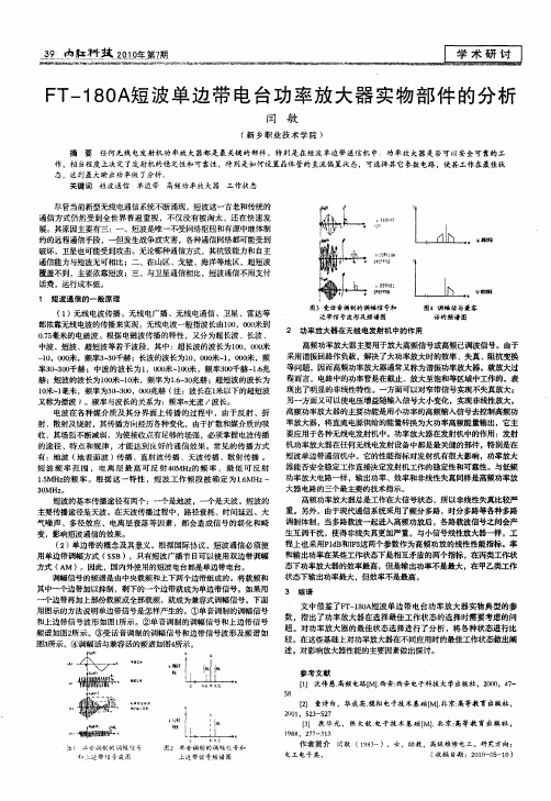
频 谱如 图2 示。③ 受话音调制的调幅信号和边带信号 波形及 频谱如 所 图3 所示。④ 调幅话与兼容话的频谱如 图4 所示。
l 一 \/
相料
籽
文 中借 鉴了F - 8A 波单边 带电 台功 率放 大器实物 典型 的参 T 10 短 数 ,指 出了功率放大器在 选择最佳 工作状态 的选择时需要 考虑 的问 题 。对功率放 大器 的最佳状态选 择进 行了分 析 ,将各种状 态进行 比 较 。在这些基础上对功率放大器在 不同应用时的最佳工作状态做出阐 述 。对影响放大器性能 的主要因素做出探讨 。
一
高频功率放大器总是工作在 大信号状态 ,所 以非线性失真比较严 重。另外 ,由于现代通信系统采用 了频分多路 ,时分多路等各种 多路 调制体制,当多路载波—起进入高频功放后,各路载波信号之问会产 生互调干扰 ,使得非线失真更加严重。与小信号线性放 大器一样 ,工 程上也采用P d 和I3 lB P 这两个参数作为高频功 放的线性性能指标。率 和输出功率在 某些工作状态下是相互矛盾的两个指 标 , 在丙类工作状 态下功率放大器 的效率最高 ,但是输 出功 率不是最大 ,在 甲乙类工作 状态下输 出功率最大 ,但效 率不是最高 。
BF998中文资料

Fig.4 Power derating curve; BF998R.
1996 Aug 01
3
元器件交易网
Philips Semiconductors
Product specification
Silicon N-channel dual-gate MOS-FETs
THERMAL CHARACTERISTICS SYMBOL Rth j-a Rth j-a Notes 1. Device mounted on a ceramic substrate, 8 mm × 10 mm × 0.7 mm. 2. Device mounted on a printed-circuit board. STATIC CHARACTERISTICS Tj = 25 °C; unless otherwise specified. SYMBOL PARAMETER CONDITIONS VG2-S = VDS = 0; IG1-SS = ±10 mA VG1-S = VDS = 0; IG2-SS = ±10 mA VG2-S = 4 V; VDS = 8 V; ID = 20 µA VG1-S = 0; VDS = 8 V; ID = 20 µA PARAMETER thermal resistance from junction to ambient in free air; BF998
Marking code: MOp.
Fig.1
Simplified outline (SOT143) and symbol; BF998.
handbook, halfpage
d 4 g2 g1
3
PINNING PIN 1 2 3 4 SYMBOL s, b d g2 g1 source drain gate 2 gate 1 DESCRIPTION
2SC4617G;2SC4617T1G;2SC4617;2SC4617T1;中文规格书,Datasheet资料
*For additional information on our Pb−Free strategy and soldering details, please download the ON Semiconductor Soldering and Mounting Techniques Reference Manual, SOLDERRM/D.
TA = - 25C 100
1
10 100 IC, COLLECTOR CURRENT (mA)
Figure 1. IC − VCE
2 VCE , COLLECTOR‐EMITTER VOLTAGE (V) TA = 25C COLLECTOR VOLTAGE (mV) 1.5 900 800 700 600 500 400 300 200 100 0 0.01 0.1 1 IB, BASE CURRENT (mA) 10 100 0 0.2 0.5 1
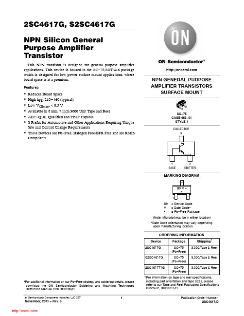
2SC4617G, S2SC4617G NPN Silicon General Purpose Amplifier Transistor
This NPN transistor is designed for general purpose amplifier applications. This device is housed in the SC−75/SOT-416 package which is designed for low power surface mount applications, where board space is at a premium.
November, 2011 − Rev. 5
1
/
2SC4617G, S2SC4617G
BFR91A中文资料
13623
1
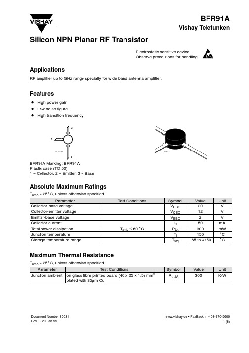
BFR91A Marking: BFR91A Plastic case (TO 50) 1 = Collector, 2 = Emitter, 3 = Base
Absolute Maximum Ratings
Tamb = 25_C, unless otherwise specified Parameter Collector-base voltage Collector-emitter voltage Emitter-base voltage Collector current Total power dissipation Junction temperature Storage temperature range Test Conditions Symbol VCBO VCEO VEBO IC Ptot Tj Tstg Value 20 12 2 50 300 150 –65 to +150 Unit V V V mA mW °C °C
Document Number 85031 Rev. 3, 20-Jan-99
www.vishay.de • FaxBack +1-408-970-5600 1 (8)
元器件交易网ຫໍສະໝຸດ BFR91AVishay Telefunken Electrical DC Characteristics
Tamb = 25_C, unless otherwise specified Parameter Collector cut-off current Collector-base cut-off current Emitter-base cut-off current Collector-emitter breakdown voltage Collector-emitter saturation voltage DC forward current transfer ratio Test Conditions VCE = 20 V, VBE = 0 VCB = 20 V, IE = 0 VEB = 2 V, IC = 0 IC = 1 mA, IB = 0 IC = 50 mA, IB = 5 mA VCE = 5 V, IC = 30 mA Symbol Min Typ Max Unit ICES 100 mA ICBO 100 nA IEBO 10 mA V(BR)CEO 12 V VCEsat 0.1 0.4 V hFE 40 90 150
BFRSP中文(拉法基专用)
引进美国富乐公司技术BFRS(P)系列反吹风袋式收尘器用户手册目录一、技术性能表二、用途、结构概述和工作原理三、安装要求四、试运行五、操作维护和检修六、润滑项目表七、易磨损件表八、性能及可靠性测试方案一、技术性能BFRS(P)系列袋式除尘器性能表二、用途、结构概述和工作原理(一)用途BFRS(P)型袋收尘器系列产品是在消化、吸收美国FULLER公司袋收尘器技术的基础上,结合我国水泥工业收尘的实际情况和需要设计的。
本系列产品主要用于水泥窑头、窑尾、碱旁路放风等扬尘点收尘。
还可以用于电力、冶金、化工等工业窑炉烟气的收尘。
根据不同工况分为高温型和常温型,高温型滤袋的材质可采用玻纤膨体纱,其允许使用的烟气温度小于260℃;常温滤料采用化学连续纤维,使用温度小于120℃。
如处理的烟气温度高于上述滤布的允许使用温度,气体进入收尘器前,必须进行降温处理或采用其它耐温滤料。
本系列收尘器由不同室数组成多种不同规格,其型号规格表示方式如下:每列室数列数(单列不写)每室名义过滤面积正压操作负压操作反吹风袋收尘器(二)结构概述BFRS(P)型袋收尘器全部采用内滤、下进风形式, 并分为正压和负压两种结构形式,用户在选型时,应根据收尘系统上正压还是负压操作来选择。
袋收尘器由壳体、灰斗、阀系统、反吹风清灰装置、压缩空气系统、测压系统及楼梯平台等部分组成。
以BFRS1200型袋收尘器为例,BFRS(P)型袋收尘器结构如图1。
图1 负压袋收尘器1、提升阀2、反吹风阀3、清扫阀4、加压阀5、手动碟阀6、电动圆板阀7、反吹风机8、轴流风机9、电动百叶窗10、反吹风管道11、走道人孔门12、滤袋悬吊架13、人孔门14、灰斗内输送拉链机15、单向螺旋闸门和刚性叶轮给料机16、减速电机17、汇总输送拉链机1、壳体袋收尘器全部采用钢结构外壳,壳体有两种类型—即标准型和用户型。
在制造厂组装成单元箱体,再运往现场,称之为标准型;而用户型,一般在制造厂壳体等主要部件制造完后,运往用户,在现场进行组装。
BFR181T资料

Applications
For low noise and high gain broadband amplifiers at collector currents from 0.5 mA to 12 mA.
Features
D Low noise figure D High power gain
1 1
Absolute Maximum Ratings
Tamb = 25_C, unless otherwise specified Parameter Collector-base voltage Collector-eme Collector current Base current Total power dissipation Junction temperature Storage temperature range Test Conditions Symbol VCBO VCEO VEBO IC IB Ptot Tj Tstg Value 15 10 2 20 2 160 150 –65 to +150 Unit V V V mA mA mW °C °C
0.1 100 100
Electrical AC Characteristics
Tamb = 25_C, unless otherwise specified Parameter Transition frequency q y Test Conditions VCE = 3 V, IC = 6 mA, f = 500 MHz VCE = 8 V, IC = 20 mA, f = 500 MHz Collector-base capacitance VCB = 10 V, f = 1 MHz Collector-emitter capacitance VCE = 10 V, f = 1 MHz Emitter-base capacitance VEB = 0.5 V, f = 1 MHz Noise figure VCE = 5 V, IC = 3 mA, ZS = ZSopt, f = 900 MHz VCE = 5 V, IC = 3 mA, ZS = ZSopt, f = 1.75 GHz Power gain VCE = 8 V, IC = 8 mA, ZS = 50 W, ZL = ZLopt, f = 900 MHz VCE = 8 V, IC = 8 mA, ZS = 50 W, ZL = ZLopt, f = 1.75 GHz Transducer gain VCE = 8 V, IC = 8 mA, f = 900 MHz, Z0 = 50 W Symbol fT fT Ccb Cce Ceb F F Gpe Gpe S21e2 Min Typ 6.8 8.0 0.3 0.2 0.4 1.5 2.2 14.8 12 14 Max Unit GHz GHz pF pF pF dB dB dB dB dB
BFR193中文资料

VCB = 10 V, IE = 0
Emitter-base cutoff current
VEB = 1 V, IC = 0
DC current gain
IC = 30 mA, VCE = 8 V
Semiconductor Group
2
Dec-11-1996
元器件交易网
RthJS
K/W
1) TS is meaering point to the pcb.
Semiconductor Group
1
Dec-11-1996
元器件交易网
BFR 193
Electrical Characteristics at TA = 25°C, unless otherwise specified. Parameter Symbol min. DC Characteristics Collector-emitter breakdown voltage Values typ. max. Unit
10 1
0.5 0.2 0.1 0.05 0.02 0.01 0.005 D=0
10 1
10 0 -7 10
10
-6
10
-5
10
-4
10
-3
10
-2
10 s 10 tp
-1
0
10 0 -7 10
10
-6
10
-5
10
-4
10
-3
10
-2
10 s 10 tp
-1
0
Semiconductor Group
5
Semiconductor Group
4
Dec-11-1996
180CST
森源石化特价批180#重油\燃料油船舶用油燃料油是成品油的一种,是石油加工过程中在汽、煤、柴油之后从原油中分离出来的较重的剩余产物。
它广泛用于船舶锅炉燃料、加热炉燃料、冶金炉和其它工业炉燃料。
燃料油主要由石油的裂化残渣油和直馏残渣油制成的,其特点是粘度大,含非烃化合物、胶质、沥青质多。
燃料油的主要技术指标有粘度、含硫量、闪点、水、灰分和机械杂质。
上海期货交易所燃料油期货的交易标的是船用18 0CST燃料油,这是燃料油品种中的一种,该品种占燃料油总量的50%-75%,约3000吨以上,其中进口180CST燃料油易于期货交割,而国产燃料油由于大多包含较多其它品种,能用于交割的不多。
船用180号燃料油是一种发热量大、燃烧性能好、储存稳定、腐蚀小、使用范围广的燃油,是大马力、中、低速船舶柴油机最经济理想的燃料,同时可做中小型喷嘴的锅炉燃料,性能很好。
1、粘度:粘度是燃料油最重要的性能指标,是划分燃料油等级的主要依据,它是对流动性阻抗能力的度量。
它的大小表示燃料油的易流性、易泵送性和易雾化性能的好坏。
目前国内较常用的是40℃运动粘度(馏分型燃料油)和100℃运动粘度(残渣型燃料油)。
2、含硫量:燃料油中的硫过高会引起金属设备腐蚀和环境污染。
根据含硫量的高低,燃料油可划分为高硫、中硫和低硫燃料油。
3、闪点:是涉及使用安全的指标,闪点过低会带来着火的隐患。
4、水分:水分的存在会影响燃料油的凝点及燃料性能,会造成炉膛熄火、停炉等事故。
5、灰分:是燃料后剩余不能燃料的部分,掺入燃料油后,会加速泵、阀磨损。
如覆盖在锅炉受热面上,使传热性变坏。
6、机械杂质:它会堵塞过滤网,造成抽油泵磨损和喷油嘴堵塞,影响正常燃料。
(二)分类作为炼油工艺过程中的最后一种产品,产品质量控制有着较强的特殊性,最终燃料油产品形成受到原油品种、加工工艺、加工深度等许多因素的制约。
根据不同的标准,可将燃料油进行以下分类:1、根据出厂时是否形成商品量,燃料油可以分为商品燃料油和自用燃料油。
FR18中文资料

Oscilliscope Note 1
(+)
0A -.25A
Notes: 1. Rise Time = 7 ns Max. Impedance = 1 megohm, 22 pF 2. Rise Time = 10 ns Max. Source Impedance = 50 Ohms
-1.0A
1 cm Time Base Set @ 50/100ns/cm
.031 typ.
Features
n FAST SWITCHING FOR HIGH EFFICIENCY n HIGH SURGE CAPABILITY n 1.0 AMP OPERATION @ TA = 55°C, WITH NO THERMAL RUNAWAY n MEETS UL SPECIFICATION 94V-0
Pulse Generator Note 2
+.5A
Reverse Recovery Characteristics tRR
Ratings at 25 Deg. C ambient temperature unless otherwise specified. Single Phase Half Wave, 60 Hz Resistive or Inductive Load. For Capacitive Load, Derate Current by 20%.
Typical Junction Capacitance...CJ (Note 1) Maximum Reverse Recovery Time...tRR Page 4-6
元器件交易网
Data Sheet
1.0 Amp FAST RECOVERY PLASTIC RECTIFIERS
180级聚酯亚胺漆包铜圆线规格书

产品名称:180级聚酯亚胺漆包圆铜线型号:#EIW / 180规格:0.100mm-2.200mm技术指标生产企业:佛山市伟奇电工材料有限公司1主题内容和适用范围本标准规定了适用于180级聚酯酰亚胺复合漆包圆铜线的工厂要求。
该标准尺寸系列根据GB6109标准进行编译。
如果用户需要特殊规格,则应由双方分别提供。
2 参考标准国标6109。
1个漆包圆绕组线第1部分一般要求国标6109漆包圆绕组线180级聚酯亚胺复合漆包圆铜线JIS C3003-1999绕组线测试方法GB / T4074-1999绕组线试验方法3漆包线结构导体为铜,涂层为聚酯酰亚胺。
4漆包线的型号型号和名称如表1所示。
技术要求应符合表2的要求。
6测试方法本标准中使用的所有试验方法,除各条款另有规定外,均参照GB / T4074的规定。
6.1导体尺寸在拉直的样品中,通过不损坏导体的方法除去绝缘层,并在沿导体圆周等分的3个位置测量裸导体的直径。
记录3个测量值取平均值作为导体直径。
6.2膜厚根据第6.1和6.3条测量漆包线的外径和导体直径,两者之差就是绝缘厚度。
6.3漆包线的子宫直径在两个位置之间测量漆包线的直径,拉直后的样品之间的距离为1米,然后在3个位置的每个位置沿绝缘线的圆周等分。
记录6个测量值并取平均值作为外径。
6.4抵抗确定1米样品的电阻R,并计算20°C R时刻的电阻值20,必须满足附表的要求。
计算公式:R20(Ω/米)= RX温度系数导体温度系数表3(标准温度为20°C)6.5在引伸计或拉伸试验机上拉伸样品以使其断裂,然后计算断裂长度增加量与原始长度的比率,以百分比表示。
伸长率应大于表4中的最小伸长率。
6.6回弹角6.6.1导体公称直径为0.200至1.600(含)根据表4中指定的圆棒直径和载荷试验,回弹角应小于表4中的最大回弹角。
6.6.2标称导体直径1.600毫米以上漆包线的最大回弹角不超过5度。
6.7圆棒缠绕公称直径1.600mm及以下,按1d倍直径缠绕测试棒后,漆膜不应破裂。
FT-180A 单边带电台改装成业余电台的方法
FT-180A 单边带电台改装成业余电台的方法FT-180A单边带电台是日本八重洲株式会社80年代生产的电台,部分在国内组装,国内有相当的一部分企事业单位及部队装备有此种电台,因本机具有6个固定的工作频率, 故使用灵活性较差, 现正趋于退役。
由于该电台采用恒温晶体振荡器及专用的上边带滤波器和下边带滤波器,工艺成熟,因此性能十分稳定,本机还具有体积小巧,配有专用的天调及输出功率大[最大输出功率可达100W]、并在其技术标准上符合我国的无线电技术标准的特点,所以,改制后作为业余电台使用,是相当理想的业余电台。
虽然该电台原设计的频率复盖是1.8---18MHZ,由于其是采用可调整的6个单频点的频率调整方法,所以,机内的选频放大的收发共用通道的谐振回路有相应于使用频段的配置。
因该机目前已停止生产,难以找到配置于业余波段谐振回路的器件。
因此,本文基于业余精神,介绍一种简便易行的方法,使之尽量利用原电台的器件通过改制后能工作在业余频段。
本文先介绍7MHZ业余频段的改制方法,其它频段的改制方法,将陆续介绍。
一、FT - 180A 单边带电台的特点:1、FT-180A单边带电台采用的是恒温晶体振荡器,因此,具有良好的温度特性和抗干扰特性。
由于所适用晶体的温度应达到+70℃度,故在改制中应特别的注意选择适用的晶体。
如果选不到合适温度的晶体,业余条件下,可断掉恒温箱的电源,从而使用一般的晶体,实践表明,频率的稳定性可完全满足要求。
2、FT-180A电台的第一本振为10.7MHZ晶体稳频的固定频率振荡器。
其第二本振频率的调整是利用波段开关切换6块晶体来完成,与第一本振的和频产生电台的工作频率。
通过两只边带滤波器,选择LSB或USB工作方式。
由于本机采用宽带功放,故混频器的输出信号必需进行选频放大后再送入宽带功放,以保证电台的通带特性和电台的其它指标。
本机的选频放大器是跟据频段的不同而固定配置的器件,在业余频段的使用时,是改制成业余电台的关建部位。
2014年4月7日发布的1BFR182W低噪声高增益广带RF接收器芯片说明书

Low Noise Silicon Bipolar RF Transistor • For low noise, high-gain broadband amplifiers at collector currents from 1 mA to 20 mA • f T = 8 GHz, NF min = 0.9 dB at 900 MHz• Pb-free (RoHS compliant) and halogen-free package with visible leads•Qualification report according to AEC-Q101 availableESD (E lectro s tatic d ischarge) sensitive device, observe handling precaution!TypeMarking Pin ConfigurationPackage BFR182W RGs1=B2=E 3=C SOT323Maximum Ratings at T A = 25 °C, unless otherwise specifiedParameterSymbol ValueUnitCollector-emitter voltage V CEO 12VCollector-emitter voltage V CES 20Collector-base voltage V CBO 20Emitter-base voltage V EBO 2Collector current I C 35mA Base currentI B 4Total power dissipation 1) T S ≤ 90 °CP tot 250mW Junction temperature T J 150°CAmbient temperature T A -65 ... 150Storage temperature T Stg -65 ... 150Thermal Resistance ParameterSymbol ValueUnitJunction - soldering point 2)R thJS240K/W1TS is measured on the collector lead at the soldering point to the pcb2For the definition of RthJS please refer to Application Note AN077 (Thermal Resistance Calculation)Electrical Characteristics at T A = 25 °C, unless otherwise specifiedParameter Symbol Values Unitmin.typ.max.DC CharacteristicsCollector-emitter breakdown voltageI C = 1 mA, I B = 0V(BR)CEO12--VCollector-emitter cutoff currentV CE = 4 V, V BE = 0V CE = 15 V, V BE = 0 V, T A = 85 °C (verified by random sampling)I CES--153070nACollector-base cutoff currentV CB = 4 V, I E = 0I CBO-130Emitter-base cutoff currentV EB = 1 V, I C = 0I EBO--50DC current gainI C = 10 mA, V CE = 8 V, pulse measuredh FE70100140-Electrical Characteristics at T A = 25 °C, unless otherwise specifiedParameter Symbol Values Unitmin.typ.max.AC Characteristics (verified by random sampling)Transition frequencyI C = 15 mA, V CE = 8 V, f = 500 MHzf T68-GHzCollector-base capacitanceV CB = 10 V, f = 1 MHz, V BE = 0 ,emitter groundedC cb-0.340.5pFCollector emitter capacitanceV CE = 10 V, f = 1 MHz, V BE = 0 ,base groundedC ce-0.26-Emitter-base capacitanceV EB = 0.5 V, f = 1 MHz, V CB = 0 ,collector groundedC eb-0.8-Minimum noise figureI C = 3 mA, V CE = 8 V, Z S = Z Sopt, f = 900 MHzI C = 3 mA, V CE = 8 V, Z S = Z Sopt, f = 1.8 GHz NF min--0.91.3--dBPower gain, maximum stable1)I C = 10 mA, V CE = 8 V, Z S = Z Sopt, Z L = Z Lopt ,f = 900 MHzG ms-19-dBPower gain, maximum available2)I C = 10 mA, V CE = 8 V, Z S = Z Sopt, Z L = Z Lopt ,f = 1.8 GHzG ma-12.5-dBTransducer gainI C = 10 mA, V CE = 8 V, Z S = Z L = 50 Ω, f = 900 MHzI C = 10 mA, V CE = 8 V, Z S = Z L = 50 Ω, f = 1.8 GHz |S21e|2--15.510--dB1G ms = |S21 / S12|2G ma = |S21e / S12e| (k-(k²-1)1/2)Total power dissipation P tot = ƒ(T S)Permissible Pulse Load R thJS= ƒ(t p)101010K/WRthJSPermissible Pulse LoadP totmax/P totDC = ƒ(t p)Ptotmax/PtotDCEdition 2009-11-16Published byInfineon Technologies AG81726 Munich, Germany2009 Infineon Technologies AGAll Rights Reserved.Legal DisclaimerThe information given in this document shall in no event be regarded as a guarantee of conditions or characteristics. With respect to any examples or hints given herein, any typical values stated herein and/or any information regarding the application of the device, Infineon Technologies hereby disclaims any and all warranties and liabilities of any kind, including without limitation, warranties of non-infringement of intellectual property rights of any third party.InformationFor further information on technology, delivery terms and conditions and prices, please contact the nearest Infineon Technologies Office (<>). WarningsDue to technical requirements, components may contain dangerous substances. For information on the types in question, please contact the nearest Infineon Technologies Office.Infineon Technologies components may be used in life-support devices or systems only with the express written approval of Infineon Technologies, if a failure of such components can reasonably be expected to cause the failure of that life-support device or system or to affect the safety or effectiveness of that device or system. Life support devices or systems are intended to be implanted in the human body or to support and/or maintain and sustain and/or protect human life. If they fail, it is reasonable to assume that the health of the user or other persons may be endangered.。
BF和F型耐腐蚀离心泵型号参数说明
BF和F型耐腐蚀离心泵
BF型耐腐蚀离心泵概述:
BF型离心泵用于输送不含固体颗粒,有腐蚀性的液体,被输送的介质温度为-20℃~105℃,泵进口压力不大于6kg/cm2。
BF型耐腐蚀离心泵参数范围:
流量Q 3.36~190.8m3/h
扬程H 5.2~100m
BF型耐腐蚀离心泵型号说明:
例:40F-65ⅡA BF180-80IA
40-吸入口直径为40mm
F-悬架式、单级单吸耐腐蚀离心泵
65-设计扬程为65m
Ⅱ-第二次改进
A-叶轮外径的改变
BF-单级单吸托架式耐腐蚀离心泵
180-泵设计点流量为180m3/h
80-泵设计点扬程为80m
I-带外装式机械密封(不带I为内装式机械密封)
A-叶轮外径的改变
长沙三昌水泵厂BF型耐腐蚀离心泵结构型式:
BF型泵为单级单吸托架式离心泵;F型泵为单级悬架式离心泵,其结构均为后开门,即叶轮从泵体的后面取出。
泵的轴封可根据用户要求装填料密封或机械密封。
轴承为滚动轴承,用脂润滑。
BF型耐腐蚀离心泵旋转方向:
从驱动方向看,F型泵为逆时针旋转;BF型泵为顺时针旋转。
BF型耐腐蚀离心泵主要零件材质:
泵的过流部件采用合金不锈钢铸造。
主要牌号有:ZG1Cr18Ni9,ZGCr18Ni12M02Ti,ZG1Cr19M02R等。
BF型耐腐蚀离心泵成套范围:
泵、电动机及公用底座配套供应。
247。
华拓FR-180-4T-1.5B变频器使用说明书
华拓FR-180-4T-1.5B变频器使用说明书
1、控制方式:即速度控制、转距控制、PID控制或其他方式。
采取控制方式后,一般要根据控制精度进行静态或动态辨识。
2、最低运行频率:即电机运行的最小转速。
3、最高运行频率:一般的变频器最大频率到60Hz,有的甚至
到400Hz,高频率将使电机高速运转。
4、载波频率:载波频率设置的越高其高次谐波分量越大,这
和电缆的长度,电机发热,电缆发热变频器发热等因素是密切相关的。
5、电机参数:变频器在参数中设定电机的功率、电流、电压、转速、最大频率,这些参数可以从电机铭牌中直接得到。
6、跳频:在某个频率点上,有可能会发生共振现象,特别在
整个装置比较高时;在控制压缩机时,要避免压缩机的喘振点。
Fluke 180LR, 180LG Line Laser Levels 用户手册说明书
180LR, 180LGLine Laser Levels用户手册August 2016 (Simplified Chinese)© 2016 Fluke Corporation. All rights reserved. Specifications are subject to change without notice.All product names are trademarks of their respective companies.有限担保和有限责任Fluke 担保在正常使用和保养的情况下,其产品没有材料和工艺上的缺陷。
从寄送之日起,担保期为三年。
部件、产品修理和服务的担保期限为 90 天。
本担保仅限于 Fluke 授权零售商的原购买人或最终用户,并且不适用于一次性电池、电缆接头、电缆绝缘转换接头或 Fluke 认为由于误用、改装、疏忽、污染及意外或异常操作或处理引起的任何产品损坏。
Fluke 担保软件能依照功能规格正常运行 90 天,并且软件是记录在无缺陷的媒介上。
Fluke 并不担保软件毫无错误或在运行中不会中断。
Fluke 授权的零售商应仅对最终用户就新的和未使用的产品提供本担保,但无权代表Fluke 公司提供额外或不同的担保。
只有通过 Fluke 授权的销售店购买的产品或者买方已经按适用的国际价格付款才能享受 Fluke 的担保支持。
在一国购买的产品需在他国修理时,Fluke 有权向买方要求负担重大修理/零件更换费用。
Fluke 的担保为有限责任,由 Fluke 决定是否退还购买金额、免费修理或更换在担保期间退还 Fluke 授权服务中心的故障产品。
如需要保修服务,请与您就近的 Fluke 授权服务中心联系,获得退还授权信息;然后将产品寄至服务中心,并附上产品问题描述,同时预付运费和保险费(目的地离岸价格)。
Fluke 不承担运送途中发生的损坏。
在保修之后,产品将被寄回给买方并提前支付运输费(目的地交货)。
Fluke 180R 180G 6R 6G 产品说明书

December 2018© 2018 Fluke Corporation. All rights reserved. Specifications are subject to change without notice. All product names are trademarks of their respective companies.6R, 6GPoint and Line Lasers 180R, 180GLine Laser LevelsUsers ManualThis Fluke product will be free from defects in material and workmanship for three years from the date of purchase. This warranty does not cover fuses, disposable batteries, or damage from accident, neglect, misuse, alteration, contamination, or abnormal conditions of operation or handling. Resellers are not authorized to extend any other warranty on Fluke’s behalf. To obtain service during the warranty period, contact your nearest Fluke authorized service center to obtain return authorization information, then send the product to that Service Center with a description of the problem.THIS WARRANTY IS YOUR ONLY REMEDY. NO OTHER WARRANTIES, SUCH AS FITNESS FOR A PARTICULAR PURPOSE, ARE EXPRESSED OR IMPLIED. FLUKE IS NOT LIABLE FOR ANY SPECIAL, INDIRECT, INCIDENTAL OR CONSEQUENTIAL DAMAGES OR LOSSES, ARISING FROM ANY CAUSE OR THEORY. Since some states or countries do not allow the exclusion or limitation of an implied warranty or of incidental or consequential damages, this limitation of liability may not apply to you.11/99Fluke CorporationP.O. Box 9090Everett, WA 98206-9090U.S.A.Fluke Europe B.V.P.O. Box 11865602 BD EindhovenThe NetherlandsООО «Флюк СИАЙЭС»125167, г. Москва,Ленинградский проспект дом 37,корпус 9, подъезд 4, 1 этажLIMITED WARRANTY AND LIMITATION OF LIABILITYTable of ContentsTitle Page Introduction (1)How to Contact Fluke (1)Safety Information (1)Product Familiarization (3)Features (3)Lasers and Optical Glass (5)Controls (6)Center Point and Accessory Mount (7)Use the Product (8)New Item Alignment (8)New Horizontal or Diagonal Alignment (8)New Vertical Alignment (9)Existing Item Alignment (10)Plumb Marks (6R, 6G Only) (11)New Plumb Marks (11)Existing Item Plumb Check (12)Square Marks (6R, 6G Only) (13)Check Product Accuracy (14)Horizontal Laser Accuracy (14)Vertical Laser Accuracy (15)Plumb Accuracy (6R, 6G Only) (16)Accessories (17)Maintenance (17)Clean the Product (17)Batteries (18)Housing Glass Insert (19)Specifications (19)i6R, 6G, 180R, 180GUsers ManualiiIntroductionThe 6R, 6G Point and Line Laser Levels and the 180R, and 180G Line Laser Levels (the Product) are battery-powered, self-leveling, professional grade instruments. The 6R and 180R emit solid red line lasers. The 6G and 180G emit solid green line lasers. The 6R and 6G also emit vertical and horizontal point lasers 90degrees from the Product. Use the Product to lay out reference points to align targets horizontally, vertically, or diagonally.NoteIf the laser beam is difficult to see, use either the SLDR or SLDG Laser Detector to accurately determine the location of the laser. See the SLDR, SLDG Users Manual.How to Contact FlukeTo contact Fluke, call one of the following telephone numbers:•Technical Support USA: 1-800-44-FLUKE (1-800-443-5853)•Calibration/Repair USA: 1-888-99-FLUKE (1-888-993-5853)•Canada: 1-800-36-FLUKE (1-800-363-5853)•Europe: +31 402-675-200•Japan: +81-3-6714-3114•Singapore: +65-6799-5566•China: +86-400-921-0835•Brazil: +55-11-3530-8901•Anywhere in the world: +1-425-446-5500Or, visit the PLS website at .To view, print, or download the latest manual supplement, visit .Safety InformationA Warning identifies conditions and procedures that are dangerous to the user. A Caution identifies conditions and procedures that can cause damage to the Product or the equipment under test.W* WarningTo prevent eye damage and personal injury:•Read all safety information before you use the Product.•Carefully read all instructions.16R, 6G, 180R, 180G Users Manual2•Do not alter the Product and use only as specified, or the protection supplied by the Product can be compromised.•Do not use the Product if it operates incorrectly.•Do not use the Product if it is altered or damaged.•Use the Product only as specified or hazardous laser radiation exposure can occur.•Do not look into the laser. Do not point laser directly at persons or animals or indirectly off reflective surfaces.•Do not look directly into the laser with optical tools (for example, binoculars, telescopes, microscopes). Optical tools can focus the laser and be dangerous to the eye.•Do not open the Product. The laser beam is dangerous to eyes.•Batteries contain hazardous chemicals that can cause burns or explode. If exposure to chemicals occurs, clean with water and get medical aid.•Do not disassemble the battery.•Repair the Product before use if the battery leaks.•The battery door must be closed and locked before you operate the Product.•Remove the batteries if the Product is not used for an extended period of time, or if stored in temperatures above 50°C. If the batteries are not removed, battery leakage can damage theProduct.•Replace the batteries when the low battery indicator shows to prevent incorrect measurements.•Be sure that the battery polarity is correct to prevent battery leakage.•Use only Fluke approved power adapters to charge the battery.•Do not short the battery terminals together.•Do not disassemble or crush battery cells and battery packs.•Do not keep cells or batteries in a container where the terminals can be shorted.•Do not put battery cells and battery packs near heat or fire. Do not put in sunlight.Table1 is a list of the symbols that can be used on the Product or in this manual.Table 1. SymbolsSymbol Description Symbol DescriptionConsult user documentation.P Conforms to European Uniondirectives.W WARNING. RISK OF DANGER Conforms to relevant Australian Safetyand EMC standards.*WARNING. LASER RADIATION.Risk of eye damage.Conforms to relevant South KoreanEMC Standards.Laser LevelsProduct FamiliarizationTable 1. Symbols (cont.)NoteIn colder climates, the Product needs sufficient time to warm up to achieve the stated accuracymeasurements. Turn on both the horizontal and vertical lasers and wait 3minutes before you take ameasurement. When you move the Product between environments with large differences in ambienttemperature, allow for an additional adjustment time.Product FamiliarizationThe manual explains features for multiple models. Because models have different features and accessories, not all of the information in the manual may apply to your Product.FeaturesUse Table2 to identify the features and standard accessories of your Product.36R, 6G, 180R, 180G Users Manual4Table 2. FeaturesLaser LevelsProduct Familiarization5Lasers and Optical GlassTable 3 shows the lasers and optical glass.Table 3. Lasers and Optical GlassItem DescriptionItem Description90°horizontal point lasers (6R, 6G only)Housing glass insert 90° vertical point lasers (6R, 6G only) Optical glassVertical line laserHousing glass insert screwsHorizontal line laser2b63751b46R, 6G, 180R, 180G Users Manual6ControlsTable4 lists the Controls of the Product.Table 4. ControlsProduct FamiliarizationCenter Point and Accessory MountFigure1 shows features that help to layout reference marks. The vertical laser is centered 1.25in (31.75mm) from both sides of the Product. To stabilize the Product and view the laser that points down, use the accessory mount to secure the Product to the magnetic L-bracket, the floor stand, or a tripod.Figure 1. Center Point and Accessory MountUsers ManualUse the ProductUse the Product to layout reference points and to make sure conditions are level and plumb.W* WarningTo prevent eye damage and personal injury, do not look into the optical windows when the Laser indicator LED shows green.New Item AlignmentNew Horizontal or Diagonal AlignmentNoteTo find diagonal alignment, use the lock feature.To identify new level or grade marks:1.Put the bottom of the Product on a stable surface.2.Turn on the horizontal laser and aim the laser at the target area. See Figure2.3.Put marks at the level or grade point on the target area.NoteWhen the Product is mounted on a tripod, make sure the tripod head is perfectly level. Errors in marks can result if a tripod is out of level.Figure 2. New Horizontal or Diagonal AlignmentUse the ProductNew Vertical AlignmentTo identify new marks that are vertically aligned:1.Put the bottom of the Product on a stable surface.2.Turn on the vertical laser and aim the laser at the target area. See Figure3.3.Put marks at the point where the vertical laser intersects the target area.Figure 3. New Vertical AlignmentUsers ManualExisting Item AlignmentTo determine if an existing item is level or aligned:1.Put the bottom of the Product on a stable surface.2.Aim the horizontal or vertical laser at the target area.3.Measure the distance from the item to the laser at various distances from the Product. See Figure4.If the measurements are the same, the item is level or aligned.Figure 4. Existing Item AlignmentUse the ProductPlumb Marks (6R, 6G Only)The Product sends plumb marks up and down.New Plumb MarksTo identify new plumb marks on a ceiling or roof:1.Place a cross mark on the point to be transposed.2.Center the down laser over the cross mark. See Figure5.3.Place a mark at the point where the up laser intersects the target area.To identify new plumb marks on a floor, repeat the steps above but interchange the down and up lasers.NoteUse the floor stand with the Product to increase the sight angle of the vertical down laser.Figure 5. New Plumb MarkUsers ManualExisting Item Plumb CheckTo determine if an existing item is plumb:1.Point either the up or down laser at the target area.2.Measure the distance from the item to the laser at various distances from the Product. See Figure6.If the measurements are the same, the item is plumb.Figure 6. Existing Item Plumb CheckUse the ProductSquare Marks (6R, 6G Only)Use the vertical and horizontal point lasers to create new square marks or to determine if an existing item is square.To layout a new square for a wall or staircase (see Figure7):1.Mark a vertical line on a wall.2.Center the vertical laser on the line on the wall.3.Place the pendulum target on the floor and align the horizontal point laser with the center vertical line on thependulum target.4.Place a mark on the floor below the point of the pendulum target.5.Move the Product either closer to or farther away from the wall and redo the procedure to make another markon the floor.6.Draw a line to connect the two marks. The new line is perpendicular to the wall.Figure 7. New SquareUsers ManualCheck Product AccuracyPeriodically check the accuracy of the Product.Horizontal Laser AccuracyTo check the accuracy of the horizontal laser:1.Find a horizontal site that is almost level that is ≥4.57m (15ft) wide with two opposing walls to use as targets.You can also use scrap wood as targets. See Figure8.Figure 8. Horizontal Laser Accuracy2.Put the Product about 15cm (6in) from target .3.Aim the horizontal laser at target .4.Put a mark at the point where the horizontal laser intersects the target area.5.Turn the Product 180° on its center so that the horizontal laser intersects with target .6.Put a mark at the point where the horizontal laser intersects the target area.7.Repeat with the Product 15cm (6in) from target .8.Measure the distance between mark and mark on target and mark and mark on target .If the distances are the same, the laser is within calibration.9.If the distances are not the same, subtract the lesser measurement from the greater measurement and dividethe result by two to calculate the difference of error.If the distance of error is ≤3mm at 10m (1/8in at 30ft), the laser is within calibration accuracy. If the Product is not within accuracy, contact Fluke. See How to Contact Fluke.Check Product AccuracyVertical Laser AccuracyTo check the accuracy of the vertical laser:1.Find a door jamb that has ∼2.29m (7.5ft) clearance on both sides of the door.2.Put a center mark on the door header an equal distance from both sides of the door jamb.3.Put a cross mark (mark 1) on the floor centered on the mark on the door header. See Figure 9.4.Put a second cross mark (mark 2) ∼2.29m (7.5ft) from mark 1. Use the vertical laser to make sure thatmark 2 is centered on the door header and intersects mark 1.5.Put the Product on mark 2 with the vertical laser on.6.Put a third cross mark (mark 3) on the floor ∼4.57m (15ft) from the Product. Use the vertical laser to makesure that mark 3 is centered on the door header and intersects mark 1.7.Put a cross mark on the door header above mark 1.8.Move the Product to mark 3 and align the laser so that it intersects the centers of marks 1 and 2.9.Put another cross mark on the door header above mark 1.10.Measure the distance between the center points of the two cross marks.If the distance is ≤3mm at 10m (1/8in at 30ft), the laser is within calibration accuracy.Figure 9. Vertical Laser Accuracy132.29 m (7.5 ft)4.57 m (15 ft)122123412= V d3 mm @ 10 m (1/8 in @ 30 ft)= OKV d x 2 ≤Users ManualPlumb Accuracy (6R, 6G Only)To check the accuracy of the plumb:1.Find a site that has a ≥2.29m (7.5ft) vertical height.2.Place a cross mark at the bottom of the site.3.Center the down point laser on both axes of the cross mark. See Figure10.Figure 10. Plumb Accuracy4.Place a cross mark at the point where the up point laser intersects the target area at the top of the site.5.Turn the Product 180° on its center.6.Repeat step3 and step4.If the first and second cross marks on the target area at the top of the site are the same, the laser is plumb.7.If the cross marks are not the same, measure the distance between the center points of the two cross marksand divide by two to calculate the difference of error.If the distance is ≤3mm at 10m (1/8in at 30ft), the laser is within calibration accuracy.Accessories AccessoriesTable5 is a list of the accessories available for the Product.Table 5. AccessoriesModel Description PNPLS FS Floor stand5031929PLS MLB Magnetic L-bracket5031934PLS BP5BP5 alkaline battery pack5031952PLS RRT4Red magnetic reflective target5022629PLS GRT4Green magnetic reflective target5022634PLS-10090Pendulum layout target, PLS54844979PLS-60573Canvas pouch4792193PLS C18Tool box4985124PLS UB9UB9 ceiling/wall bracket4966636PLS-HGI6R Housing glass insert for 6R5042456PLS-HGI6G Housing glass insert for 6G5067785PLS-HGI180R Housing glass insert for 180R5042463PLS-HGI180G Housing glass insert for 180G5067797MaintenanceTo maintain the Product, clean the case and optical glass and replace the batteries.W* WarningTo prevent eye damage and personal injury, do not open the Product. The laser beam is dangerousto the eyes.W CautionTo prevent damage to the Product, do not drop the Product. Treat the Product as a calibrated instrument.Clean the ProductClean the case with a damp cloth and a weak soap solution.W CautionTo prevent damage to the Product, do not use abrasives, isopropyl alcohol, or solvents to clean the case or optic windows.To clean the optical glass, use a pressurized can of air or a dry nitrogen-ion gun, if available, to blow off particulates from the optical surfaces.Users ManualBatteriesReplace the batteries when the battery indicator LED is red.To install or replace AA batteries (see Figure11):1.Open the battery compartment.2.Install three AA batteries. Observe the correct polarity.3.Close the battery compartment.Figure 11. Battery ReplacementSpecificationsHousing Glass InsertIf the optical glass is damaged, replace the housing glass insert. See Table5 for the part number to order for your Product.To replace the housing glass insert (see Figure12):1.Remove the five housing glass insert screws. Note the proper placement of each screw because the screwsare different sizes.2.Pull out the housing glass insert.3.Replace the insert and screws.Figure 12. Housing Glass Insert ReplacementSpecificationsBatteries 3 x AA Alkaline IEC LR6Battery life, continuous use, both lasers, as testedRed≥8hoursGreen≥3hoursPoint laser direction (6R and 6G only)90° up, down, left, rightLine fan angleHorizontal≥180°Vertical≥130°Users ManualWorking rangePoint laser (6R and 6G only)≤30m (100ft)Line laserWithout SLD≤15m (50ft)With SLD6m to 60m (20ft to 200ft) Accuracy≤3mm at 10m (≤1/8in at 30ft) Laser leveling4°Point laser diameter (6R and 6G only)≤4mm at 5mLine laser width≤2mm at 5mTemperatureOperating-10°C to 50°C (14°F to 122°F) StorageWith batteries-18°C to 50°C (-0.4°F to 122°F) Without batteries-20°C to 70°C (-13°F to 158°F)Relative humidity 0% to 90% (0°C to 35°C) 0% to 75% (35°C to 40°C) 0% to 45% (40°C to 50°C)Size (H x W x L)116mm x 64mm x 104mm (4.6in x 2.5in x 4.1in)Weight∼0.6kg (1.3lb)Drop test1mSafety IEC 61010-1: Pollution Degree2Laser IEC 60825-1:2014 Class 2Light source Semiconductor laser diodeMax output power<1mWWavelengthRed635nm ±5nmGreen525nm ±5nmElectromagnetic Compatibility (EMC)International IEC 61326-1: Basic Electromagnetic EnvironmentCISPR 11: Group 1, Class BGroup 1: Equipment has intentionally generated and/or uses conductively-coupled radio frequency energy that is necessary for the internal function of the equipment itself.Class B: Equipment is suitable for use in domestic establishments and in establishments directly connected to a low voltage power supply network which supplies buildings used for domestic purposes.Emissions that exceed the levels required by CISPR 11 can occur when the equipment is connected to a test objectKorea (KCC)Class B Equipment (Broadcast communications equipment for home)USA (FCC)47 CFR 15 subpart B. This product is considered an exempt device per clause 15.103.。
森海塞尔(Sennheiser)RS180中文说明书

镍氢电池的安全说明 若电池使用不当,可能导致电池泄漏。在各种极端条件下存在危险:
• 过热 • 着火 • 爆炸 • 产生烟雾或有害气体
Sennheiser 对未按照规范使用造成的后果不承担责任。
不要放置在儿童所能触 及的地方。
注意正确的极性。
请使用 Sennheiser 推荐的电 池。
不得短路连接。
不得受潮。
对于明显损坏的产品, 应立刻取出电池。
将旧电池交给专业回收点或专 业经销商妥善处理。
3
数码无线耳机系统 RS 180
数码无线耳机系统 RS 180
RS 180 是一款多种技术配置合成的无线耳机系统。其纯净均衡的音质以 及高品质的低音输出使这款耳机成为音响、家庭影院和电视机的最佳选 择。 电池安装简单。享受自由的音效体验、高品质设计以及最佳的舒适度。
• 在使用此通讯耳机前请仔细完整地阅读本说明。
• 为了便于今后使用,请保管好本说明,以便所有使用者在任何时候都 可以参阅。请始终将通讯耳机连同本使用说明一起交给第三方。
• 请勿在需要集中注意力时使用本产品(如在行车途中或在从事手工作 业时)。
• 保持耳机干燥,不要将耳机暴露在极低或极高的温度下 (理想温度: 0°C 至 40°C)。
请在使用后关闭耗电产品。
不得将充电后的电池裸 露、混合存放。
电池充电的环境温度 许可范围为 10°C/50°F 至 40°C/104°F。 不得拆卸或扭曲。
对于长期不使用的充电 电池定期进行充电 (大约每三个月)。
电池温度不得超过 70°C/158°F,比如: 受阳光照射或投入火中。
不得继续使用受损电池。
5
产品总览
产品总览
HDR 180 耳机一览
BEDFORD变频器说明书

B801系列使用手册V1.4目录1、前言 (1)2、安全注意事项 (1)3、产品检查3.1检查步骤 (1)3.2型号说明 (1)4、安装4.1外型尺寸 (2)4.2使用环境 (2)4.3注意事项 (2)5、配线5.1基本接线图 (4)5.2操作注意 (5)6、数字操作器使用方法6.1显示器及操作键 (5)6.2操作键的使用 (5)7、测试运转 (6)7.1掌握一些相应的调节方法或许能让您获得更理想的使用效果 (6)7.2键盘操作模式 (6)7.3键盘操作正、反转模式 (7)7.4控制端子操作模式 (7)7.5参数恢复出厂设定值 (7)7.6参数修改后储存条件 (7)8、显示屏上的符号解释 (8)9、参数和数据表9.1参数一览表 (11)9.2参数说明 (13)10、故障指令及对策10.1故障发生时处理排除的注意事项 (18)10.2异常故障处理对策表 (18)10.3运转注意事项 (19)11、B801-200V系列标准规格 (20)12、B801-400V系列标准规格 (21)1、前言感谢您选用B801系列高性能变频器,使用前务必请认真阅读本说明书。
2、安全注意事项变频器是电力电子新产品,为了您的安全,本手册中有“危险”“注意”等符号是提醒您在搬运、安装、运转、检查变频器时的安全防范事项。
! 危险错误使用时,可能造成人员伤亡。
! 注意错误使用时,可能造成变频器或系统损坏。
3、产品检查3.1检查步骤•变频器是否符合所订购的型号与规格。
•检查在运输过程中,变频器是否因运送不慎造成损伤,若有损坏请勿接入电源。
•保修单编号是否与变频器一致。
当您发现有上述问题时,请立即通知有关销售商的业务人员。
3.2型号说明4、安装4.1外型尺寸4.2使用环境变频器安装的环境对变频器正常功能的发挥及其使用寿命有直接的影响,因此,变频器安装的环境必须符合下列条件:•周围温度:壁挂型,-10~45℃;柜内封闭型,-10~40℃。
- 1、下载文档前请自行甄别文档内容的完整性,平台不提供额外的编辑、内容补充、找答案等附加服务。
- 2、"仅部分预览"的文档,不可在线预览部分如存在完整性等问题,可反馈申请退款(可完整预览的文档不适用该条件!)。
- 3、如文档侵犯您的权益,请联系客服反馈,我们会尽快为您处理(人工客服工作时间:9:00-18:30)。
-
10 2 -7 10
10
-6
10
-5
10
-4
10
-3
10
-2
10 s 10 tp
-1
0
10 0 -7 10
10
-6
10
-5
10
-4
10
-3
10
-2
10 s 10 tp
-1
0
Semiconductor Group
5
Feb-04-1997
元器件交易网
BFR 180
Collector-base capacitance Ccb = f (VCB) VBE = vbe = 0, f = 1MHz
0.5
1.0
1.5
2.0
2.5
GHz f
3.5
Semiconductor Group
7
Feb-04-1997
V(BR)CEO
8 100 -
V µA 100 nA 100 µA 1 30 200
IC = 1 mA, IB = 0
Collector-emitter cutoff current
ICES ICBO IEBO hFE
VCE = 10 V, VBE = 0
Collector-base cutoff current
RthJS
K/W
1) TS is measured on the collector lead at the soldering point to the pcb.
Semiconductor Group
1
Feb-04-1997
元器件交易网
BFR 180
Electrical Characteristics at TA = 25°C, unless otherwise specified. Parameter Symbol min. DC Characteristics Collector-emitter breakdown voltage Values typ. max. Unit
24
Power Gain |S21|2= f(f)
VCE = Parameter
10
IC=1mA
dB dB
IC=1mA
G
20 18 16 14 12 10 8 6 4 0.0 10V 1V 0.7V 0.5 1.0 1.5 2.0 2.5 GHz f 3.5
S21
8 7 6 5 4 10V 3 2 1 0 0.0 1V 0.7V
1) Gms = |S21/S12|
Semiconductor Group
3
Feb-04-1997
元器件交易网
BFR 180
SPICE Parameters (Gummel-Poon Model, Berkeley-SPICE 2G.6 Syntax) : Transistor Chip Data IS = 0.18519 fA VAF = NE = VAR = NC = RBM = CJE = TF = ITF = VJC = TR = MJS = XTI = 26.867 1.9818 3.2134 1.6195 60 3.2473 14.866 1.0202 1.1812 2.2648 0 3 V V Ω fF ps mA V ns BF = IKF = BR = IKR = RB = RE = VJE = XTF = PTF = MJC = CJS = XTB = FC = 94.687 20.325 1.4255 3.7045 1.1812 0.3062 0 0.30423 0 0 0.87906 Ω Ω V deg fF NF = ISE = NR = ISC = IRB = RC = MJE = VTF = CJC = XCJC = VJS = EG = TNOM 1.0236 130.93 0.93013 6.1852 0.01 0.56 0.41827 0.22023 183.69 0.08334 0.75 1.11 300 fA fA mA Ω V fF V eV K
VCE = 5 V, f = 1 MHz
Emitter-base capacitance
Ceb
-
VEB = 0.5 V, f = 1 MHz
Noise figure
F
IC = 1 mA, VCE = 5 V, ZS = ZSopt f = 900 MHz f = 1.8 GHz
Power gain
1)
|S21 |2 = f(VCE):---------
Intermodulation Intercept Point IP3=f(IC)
(3rd order, Output, ZS=ZL=50Ω)
f = Parameter
16
VCE = Parameter, f = 900MHz
10 dBm 6 0.9GHz 3V 2V 2 8V 5V
VCEO VCES VCBO VEBO IC IB Ptot Tj TA Tstg
1)
TS ≤ 127 °C
Junction temperature Ambient temperature Storage temperature Thermal Resistance Junction - soldering point
0.025252 A 0.012138 A
All parameters are ready to use, no scalling is necessary. Extracted on behalf of SIEMENS Small Signal Semiconductors by: Institut für Mobil-und Satellitenfunktechnik (IMST) © 1996 SIEMENS AG
Package Equivalent Circuit: LBI = LBO = LEI = LEO = LCI = LCO = CBE = CCB = CCE = 0.85 0.51 0.69 0.61 0 0.49 73 84 165 nH nH nH nH nH nH fF fF fF
Valid up to 6 GHz For examples and ready to use parameters please contact your local Siemens distributor or sales office to obtain a Siemens CD-ROM or see Internet: http://www.siemens.de/Semiconductor/products/35/35.htm
IC=1mA
dB
G
IP3
4
12
0 1.8GHz -2 -4 -6 1V
10
8
0.9GHz
-8 -10 -12
6
1.8GHz
-14 -16 -18 0.0
4 0 2 4 6 8 V 12
1.0
2.0
3.0
4.0
V CE
mA IC
6.0
Power Gain Gma, Gms = f(f)
VCE = Parameter
12 1V 10 0.7V 8 6 1V 4 8 2V
6
0.7V
4 0 1 2 3 4 mA IC 6
2 0 1 2 3 4 mA IC 6
Semiconductor Group
6
Feb-04-1997
元器件交易网
BFR 180
Power Gain Gma, Gms = f(VCE):_____
元器件交易网www.ຫໍສະໝຸດ
BFR 180
NPN Silicon RF Transistor • For low-power amplifiers in mobile communication systems (pager) at collector currents from 0.2mA to 2.5mA • fT = 7GHz F = 2.1dB at 900MHz
VCB = 8 V, IE = 0
Emitter-base cutoff current
VEB = 1 V, IC = 0
DC current gain
IC = 1 mA, VCE = 5 V
Semiconductor Group
2
Feb-04-1997
元器件交易网
BFR 180
Semiconductor Group
4
Feb-04-1997
元器件交易网
BFR 180
Total power dissipation Ptot = f (TA*, TS)
* Package mounted on epoxy
40
mW
Ptot
30
25
TS
20
TA
15
10
5 0 0 20 40 60 80 100 120 °C 150 TA ,TS
Package SOT-23
Maximum Ratings Parameter Collector-emitter voltage Collector-emitter voltage Collector-base voltage Emitter-base voltage Collector current Base current Total power dissipation Symbol Values 8 10 10 2 4 0.5 mW 30 150 - 65 ... + 150 - 65 ... + 150 ≤ 780 °C mA Unit V
Electrical Characteristics at TA = 25°C, unless otherwise specified. Parameter Symbol min. AC Characteristics Transition frequency Values typ. max. Unit
