MRS-2-6CSKGX中文资料
计算机网络课程设计--校园网方案
计算机工程学院课程设计报告设计名称:计算机网络课程设计姓名:学号:专业班级:系(院):计算机工程学院设计时间: 2013.7.1~2013.7.14 设计地点:计算机网络实验室5、安全与管理需求:校园网内存有所有学生的考务信息、教务信息,因此对数据的保密性、完整性有较高要求。
为了今后管理的方便与维护的简单需要网络系统具有较高的易操作性6、现有网络的分析:现在的校园网实现了资源的共享,学生考试机器化,校内新闻的发布于公示,学生的管理包括网上选课、网上查询考试成绩等,实现了办公自动化,提高了工作效率。
为了适应新的教学与管理需要加强校区之间的联系,信息与资源的共享,提高办公效率和水平,我们需要建立一个更加系统,实用的全面的高速网络,提高教学的工作效率。
2、网络的拓扑方案设计2.1 总体的拓扑方案,如图1,图1 总体拓扑结构2.2 各个楼宇拓扑方案2.2.1、D2(网络中心)如图2所示,D2作为网络中心,需要有强大的中心交换机,它可以给用户提供FTP服务、邮件服务、万维网服务。
主要的设备:中心交换机1台(13个光口),汇聚交换机一台(8口),用来把每一个楼层的的接入交换机连接在一起——为什么要选用?,接入交换机6台(16口),路由器一台,防火墙1个,FTP服务器、WEB服务器、E-mail服务器、网管主机一台图2 网络中心拓扑结构2.2.2、D1(教学楼)设计如图3,主要设备:汇聚交换机交换机一台(8个电口1个光口),三级交换机6台(16口),用光纤连接到中心交换机图3 教学楼D1的拓扑结构2.2.3、D3教学楼的拓扑结构如图4,主要设备:接入交换机4台(16口),汇聚交换机(1个光口8个电口),光纤连接到主交换机图4 D3的拓扑结构2.2.4、行政楼拓扑结构如图5,这里有教务管理系统,办公系统,需要较快的网速设置一个汇聚交换机与中心交换机相连。
主要设备:汇聚交换机(1光口8个电口),4个接入交换机(16口)教务管理服务器,办公服务器图5 行政楼的拓扑结构2.2.5、图书馆的拓扑结构图,如图6,图书馆是阅览室里面有图书管理系统,视频点播系统,网管主机,教室,还有一个电子阅览室主要设备:一台汇聚交换机(1个光口8个电口),3个16口的接入交换机1个48口接入交换机一个24口接入交换机图6 图书馆拓扑及认购2.2.6、宿舍楼这其中包括豫州书院、瀛洲书院、淩州书院、女生4号楼、女生5号楼、海州书院、女生6、7号楼。
艾默生 Commander SK 2~6型 交流变速驱动器 说明书

1 ڔཝቧᇦ ..................................................7
1.1 警告、小心及注意 .................................................7 1.2 电气安全 - 一般警告 ............................................7 1.3 系统设计及人身安全 ..............................................7 1.4 环境要求 ................................................................7 1.5 操作 .......................................................................7 1.6 防火保护 ................................................................7 1.7 遵守规定 ................................................................7 1.8 电机 .......................................................................7 1.9 调整参数 ................................................................7 1.10 电气安装 ................................................................7 1.11 机械安装 ................................................................8
3M Scotchcast Electrical Resin 262 产品介绍说明书

002623M™ Scotchcast™ Electrical Resin 262 One-Part, Class B, General PurposeEpoxy Powder ResinProduct Description3M™ Scotchcast™ Electrical Resin 262 is a widely used, well-known general purpose epoxy powder resin. A one-part, red pigmented, rapid heat-curing product, it is designed to provide a continuous, tough moisture and chemical resistant dielectric coating to a variety of substrates.• Fast curing• Excellent electrical properties• Excellent thermal shock and impact resistance• Excellent heat, chemical and moisture resistance• Good cut-through resistance• Excellent flow Scotchcast Electrical resin 262 is manufactured by a fusion blend process, insuring that each individual particle of powder contains all the components necessary to effect a complete cure and attain stated performance properties.Scotchcast electrical resin 262 is applied to an object that has been heated to a temperature above the melting point of the resin. On contact with the preheated application surface, the resin melts, flows to a controlled extent, then cures, bonding to the substrate and coalescing into a smooth, continuous, essentially uniform, thick coating. It effectively coats flat surfaces and corners, as well as, high points. Uses for Scotchcast 262 include moisture proofing and insulating armatures, stators, buss bars and toroid cores.Scotchcast™ Electrical Resin 262 – Typical PropertiesColor RedSpecific Gravity1 (cured) 1.34Dielectric Strength3 12 to 15 mil coating1000 v/milThermal Shock2 10 cycles-75°C to 155°C12 -15 mil coating 1/8’’ sandblasted steel PassesImpact Resistance212-15 mil coating 1/8’’ sandblasted steel panel Gardner 5/8’’ RadiusImpact Tester100 inch-lbsCut-Through Resistance2 – 1lb wt: 1/8 AWG wire130°C (266° F)Edge Coverage2 12-15 mil coating on flat38-48%Gel time2 @ 193°C hot plate12-16 seconds*Not recommended for specification purposes. Product specifications will be provided upon request.Test Methods1 ASTM D-7922 3M Test Method3 ASTM D-14933Corrosion Protection Products Division6801 River Place Blvd. Austin, TX 78726-9000 /corrosion Please recycle. Printed in USA.© 3M 2010. All rights reserved. 80-6111-0945-7 Rev AHandling and Safety PrecautionsRead all Health Hazard, Precautionary and First Aid,Material Safety Data Sheet, and/or product label prior to handling or use.Ordering Information/Customer ServiceFor ordering technical or product information, or a copy of the Material Safety Data Sheet, call:Phone: 800/722-6721 or 512/984-9393Fax: 877/601-1305 or 512/984-6296Important NoticeAll statements, technical information, and recommendations related to 3M’s prod-ucts are based on information believed to be reliable, but the accuracy or com-pleteness is not guaranteed. Before using this product, you must evaluate it and determine if it is suitable for your intended application. You assume all risks and liability associated with such use. Any statements related to the product which are not contained in 3M’s current publications, or any contrary statements contained on your purchase order shall have no force or effect unless expressly agreed upon, in writing, by an authorized officer of 3M.Warranty; Limited Remedy; Limited Liability. Because conditions of product use are outside of our control and vary widely, the following is made in lieu of all express or implied warranties: this product will conform to 3M’s published product specifications and be free from defects in material and manufacture on the date of your purchase. 3M MAKES NO OTHER WARRANTIES INCLUDING, BUT NOT LIMITED TO, ANY IMPLIED WARRANTY OF MERCHANTABILITY OR FITNESS FOR A PARTICULAR PURPOSE. If this product is defective upon your receipt, your exclusive remedy shall be, at 3M’s option, to replace the 3M product or refund the purchase price of the 3M product. Except where prohibited by law, 3M will not be liable for any indirect, special, incidental or consequential loss or damage arising from this 3M product, regardless of the legal theory asserted.Usage InformationMethod of ApplicationThe rapid cure of 3M™ Scotchcast™ Electrical Resin 262 permits the use of highspeed production methods. The powder can be readily applied by spraying techniques as well as through the use of fluid bed dipping of preheated parts. Automated and manual types of application equipment are both available. Equipment manufacturers’ names can be suggested upon request.CuringThe cure of Scotchcast 262 to a thermoset condition involves a time-temperature relationship. The retained heat in application units having high heat capacity is sufficient in many casesto effect a cure of the resin without the need for post-curing facilities. For example, if an application surface can retain a temperature of 204° C (400° F) for 60 seconds after coating, it will be fully cured. Small articles, or those with a large surface-to-mass ratio, lose heat rapidly and may require a higher preheat temperature and/or additional oven- curing.The figures below represent nominal guidelines for obtaining the resin’s adhesion, impact and chemical resistance characteristics.149° C (300° F)40 minutes177° C (350° F)20 minutes204° C (400° F)60 seconds232° C (450° F)30 secondsThe user must determine the time required for the coated substrate to reach listed temperatures.Preheat Temperature RangePrior to applying Scotchcast electrical resin 262, the part must be preheated to a temperature ranging from 150° C (302° F) to 260° C (500° F). The optimum preheat temperature depends upon the size, heat capacity and configuration of the object to be coated, as well as the method of application. The ideal coating temperature will vary for each application and is best determined by experimentation.StorageLaboratory evaluation indicates that the usable shelf life of the product is twenty four (24) months from the date of manufacture when stored at temperatures not exceeding 27° C (80° F), providing the material is stored in its original container. Care should be taken when removing the resin from the original container to prevent inclusion of foreign material. After the resin removal, the bag should be retied immediately. This will help to avoid agglomeration caused by excess moisture. For best results, store in a cool, dry place.00262。
SL2.2S规格书,usb HUB大全,替换FE1.1S,GL850,GL852,PL2586
USB2.0 HUB控制器集成电路USB 2.0 HIGH SPEED 4-PORT HUB CONTROLLERSL2.2s数据手册Data Sheet内容目录第一章管脚分配 (3)1.1 SL2.2S管脚图 (3)1.2 SL2.2S管脚定义 (3)第二章 功能叙述 (5)2.1综述 (5)2.2指示灯 (5)2.2.1单灯方案 (5)2.2.2多灯方案 (6)2.2.3 LED指示定义 (6)2.3过流保护 (6)2.4充电支持 (6)2.5I2C接口 (7)2.6EEPROM设置 (7)第三章电气特性 (8)3.1极限工作条件 (8)3.2工作范围 (8)3.3直流电特性 (8)3.4HS/FS/LS电气特性 (8)3.5ESD特性 (8)附录一封装 (9)表格目录表格1: 端口LED定义 (6)表格 2 : ACTIVE LED定义 (6)表格3:EEPROM数据结构定义 (7)表格4: 最大额定值 (8)表格5: 工作范围 (8)表格6: 直流电特性 (8)插图目录图1:SSOP28 管脚图 (3)图2:单灯方案配置 (5)图3: 5灯方案配置 ............................................................................... (6)图 4:附录 封装图 ................................................................................... .9第一章管脚分配1.1SL2.2s管脚图图1:SSOP28 管脚图1.2SL2.2s管脚定义管脚名称28Die IO类型定义Pin#VSS 1 P 芯片地XOUT 2 O晶振PAD XIN 3 IDM4 4 B下行口4的USB信号DP4 5 BDM3 6 B下行口3的USB信号DP3 7 BDM2 8 B下行口2的USB信号DP2 9 BDM1 10 B下行口1的USB信号DP1 11 BVDD18 12 P 模拟1.8vVDD33 13 P 模拟3.3v - 14 NCUDM 15 B上行口的USB信号UDP 16 BRESET_N 17 I,Pu 芯片外部复位输入- 18 NCPSELF 19 I,Pu 高为自供电,低为总线供电VDD5 20 P 5v输入VDD33 21 P 3.3v输出DRV 22 B,Pu 点灯驱动信号LED1 23 B,Pu 点灯驱动信号LED2 24 B,Pu 点灯驱动信号PWRN 25 B,Pu 下行口电源输出控制,低有效OVCRN/SDA 26 B,PuI2C SDA数据线,内部上拉;芯片初始化完成后作为过流保护输入脚,低有效SCL 27 B,Pu I2C SCL时钟输出VDD18 28 P 数字1.8v注释:O,输出;I 输入;B 双向;P 电源/接地;Pu 上拉;Pd 下拉;NC 悬空;第二章 功能叙述2.1综述SL2.2s 是一颗高集成度,高性能,低功耗的USB2.0集线器主控芯片;该芯片采用STT 技术,单电源供电方式,芯片供电电压为5v , 内部集成5V 转3.3V,只需在外部电源添加滤波电容;芯片自带复位电路,低功耗技术让他更加出众。
BNS 260 产品说明书
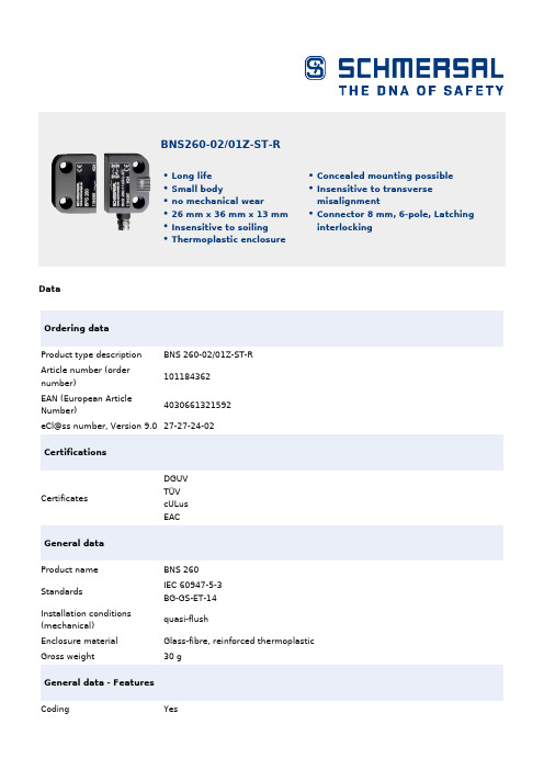
DataOrdering dataProduct type descriptionBNS 260-02/01Z-ST-R Article number (ordernumber)101184362EAN (European ArticleNumber)4030661321592eCl@ss number, Version 9.027-27-24-02CertificationsCertificates DGUVTÜVcULus EACGeneral dataProduct nameBNS 260StandardsIEC 60947-5-3 BG-GS-ET-14 Installation conditions(mechanical)quasi-flush Enclosure materialGlass-fibre, reinforced thermoplastic Gross weight 30 gGeneral data - FeaturesCoding Yes BNS260-02/01Z-ST-RLong lifeSmall bodyno mechanical wear26 mm x 36 mm x 13 mmInsensitive to soilingThermoplastic enclosure Concealed mounting possible Insensitive to transverse misalignment Connector 8 mm, 6-pole, Latching interlockingNumber of openers3Number of safety contacts2Safety appraisalStandards ISO 13849-1Mission Time20 Year(s)Safety appraisal - Safety outputsB10d Normally-closed25,000,000 Operationscontact (NC)Mechanical dataActuating element MagnetDoor hinge RightEnsured switch distance5 mm"ON" SaoEnsured switch distance15 mm"OFF" S arAxial misalignment, a horizontal and vertical misalignment of the safety sensorand the actuator are tolerated. The possible misalignment depends on thedistance of the active surfaces of the sensor and the actuator. The sensorremains active within the tolerance range.Direction of motion Head-on to the active surfaceMechanical data - Connection techniqueTerminal Connector Connector 8 mm, 6-pole, Latching interlockingMechanical data - DimensionsHeight of sensor36 mmLength of sensor13 mmWidth of sensor26 mmAmbient conditionsProtection class IP67Ambient temperature,-25 °CminimumAmbient temperature,+70 °CmaximumStorage and transport-25 °Ctemperature, minimumStorage and transport+70 °Ctemperature, maximumResistance to vibrations to10 … 55 Hz, amplitude 1 mmEN 60068-2-6Restistance to shock30 g / 11 msElectrical dataVoltage type DC (direct current)Switching voltage, maximum30 VDCSwitching current, maximum0.4 ASwitching capacity,10 VAmaximumSwitching frequency,5 HzmaximumScope of deliveryIncluded in delivery Actuators must be ordered separately.AccessoryRecommendation (actuator)BPS 260SRB-E-301STSRB-E-201LCNotesNote (General)The number in brackets indicate the PIN number of the connector. Circuit exampleNote (Wiring diagram)Contact S21-S22 and S11-S12 must be integrated in the safety circuit. Ordering codeProduct type description:BNS 260-(1)(2)Z(3)-(4)-(5)(1)11 1 NO contacts/1 NC contact02 2 NC contact(2)without with diagnostic output/01 1 NC contact(3)without without LED switching conditions displayG with LED switching conditions display(4)without Pre-wired cableST with connector(5)L Door hinge on left-hand sideR Door hinge on right-hand sidePicturesProduct picture (catalogue individual photo)ID: kbns2f04| 42,3 kB | .png | 74.083 x 60.325 mm - 210 x 171Pixel - 72 dpi| 63,6 kB | .jpg | 27.093 x 22.013 mm - 320 x 260 Pixel- 300 dpi| 540,4 kB | .jpg | 352.778 x 287.161 mm - 1000 x 814Pixel - 72 dpiDimensional drawing basic componentID: 1bns2g03| 17,8 kB | .jpg | 112.889 x 78.317 mm - 320 x 222Pixel - 72 dpi| 24,9 kB | .cdr || 61,2 kB | .jpg | 352.778 x 245.181 mm - 1000 x 695Pixel - 72 dpi| 2,9 kB | .png | 74.083 x 51.506 mm - 210 x 146 Pixel- 72 dpiDiagramID: kbns2k24| 84,9 kB | .jpg | 352.778 x 99.483 mm - 1000 x 282Pixel - 72 dpiCharacteristic curveID: kbns2d03| 36,8 kB | .cdr || 40,4 kB | .jpg | 112.889 x 74.789 mm - 320 x 212Pixel - 72 dpi| 18,5 kB | .png | 74.083 x 49.036 mm - 210 x 139Pixel - 72 dpiCharacteristic curveID: kbns2d02| 19,2 kB | .png | 74.083 x 49.389 mm - 210 x 140Pixel - 72 dpi| 40,8 kB | .jpg | 112.889 x 75.142 mm - 320 x 213Pixel - 72 dpi| 36,3 kB | .cdr |ClipartID: kbns2c01| 20,1 kB | .cdr || 1,7 kB | .png | 74.083 x 52.564 mm - 210 x 149 Pixel- 72 dpiContact arrangement| 17,4 kB | .cdr |K.A. Schmersal GmbH & Co. KG, Möddinghofe 3, D-42279 WuppertalThe details and data referred to have been carefully checked. Images may diverge from original. Further technical data can be found in the manual. Technical amendments and errors possible.Generated on 08.07.2020 19:09:09。
Hoffman Enclosures Inc. 电子变压器操作适配器(适用于Eaton Cutle

89115496
© 2018 Hoffman Enclosures Inc.
PH 763 422 2211 • /HOFFMAN
-3-
For Floor-Mounted, Two-Door Enclosures with Disconnect on Right Flange
0DVWHU 'RRU
)RURQHWKURXJKVL[GRRUIUHHVWDQGLQJHQFORVXUHV ZLWKWKHGLVFRQQHFWWKHWKHULJKWIODQJH 0DVWHU 'RRU
)RUIORRUPRXQWHGHQFORVXUHVZLWK WKHGLVFRQQHFWRQWKHFHQWHUSRVW
Step 5 Attach the bottom of the slide arm (item 4) to the offset arm of the lock release mechanism. Use two flat washers (item 8), two lockwashers (item 9), and two hex nuts (item 10). Do not tighten until parts are adjusted (see step 6B)
Item No. Description
Part No.
Qty.
1
MOUNTING PLATE, C-H C361 AND C371
26385001
1
2
GASKET, PLATE
89109613
1
3
SCREW, 1/4-20X1/2 PAN HEAD
99401031
4
4
科迈ComApMRS发电机组控制器说明书

科迈ComAp?MRS?16发电机组控制器说明书1、概述:科迈公司生产的InteliLite NT MRS 16自启动控制器集测量、控制保护(例如:低油压、高水温、低燃油位、欠速、超速、欠频、过频、欠压、过压、过流、过载等)、显示(例如:油压、水温、油位、发电电压、电流、转速、发电频率、功率、功率因素、电能、运行时间、启动次数、故障清单、辅助输入与输出功能等等,均能从前面板的液晶屏直观看出)等众多功能为一体,超宽(8V-35V)的直流工作电压,能满足发电机使用者对不同类型发电机组的自动控制需求。
模块中内含功能强大的微处理器,可实现一系列复杂功能:●用户可对液晶屏进行中文或英文显示界面切换;●控制器能实现对机组的运行状态和故障情况进行监控、预警和停机等;●用户完全可根据机组需要在面板上对控制器进行各种参数设置(例如:电流互感器、飞轮齿数、怠速时间等等);●用户可通过RS232或USB专用通讯接口和PC机连接进行各种控制工作模式配置、参数设置及监控;●可完全设置的6个辅助输入(用户可自编程定义)和6个辅助输出端,可用于启动、警报或停机等其它功能;●用户可根据需要使用扩展模块提供多种扩展输入输出功能;●自启动和停止发电机组( 控制器为“自动”模式),当市电电压断电时(安装市电断电继电器,任选一个辅助输入作市电的有无状态监测),机组将进行自启动,然后向负载供电,如果市电回来时,机组将停机,市电向负载供电。
注意:本说明书仅适应InteliLite NT MRS 16,凡使用前必须先参阅本说明书;若有更改,恕不另行通知。
2、控制器外形结构与连线背面接线简图注:上图的辅助输入及辅助输出为出厂默认设置,用户可通过RS232或USB专用通讯接口和PC机连接进行各种控制工作模式配置、参数设置及监控,厂家也可根据用户的要求在出厂时预设各种控制工作模式的配置;▲!所有辅助输出外接继电器(JK)必须接保护二极管(D),否则容易导致控制器硬件损坏而影响机组正常使用。
SK26A中文资料
88 -65 to +125 -65 to +150 -65 to +150
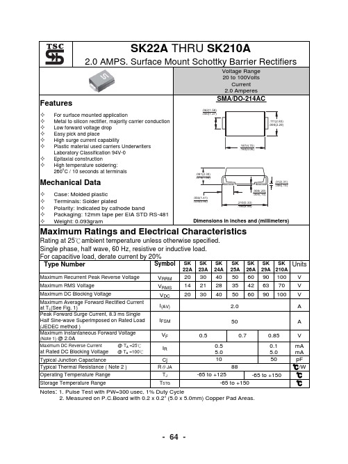
Notes: 1. Pulse Test with PW=300 usec, 1% Duty Cycle 2. Measured on P.C.Board with 0.2 x 0.2” (5.0 x 5.0mm) Copper Pad Areas.
4A
2 SK 6A
TJ=125 C
10
25
A-
SK
1
29
S A-
K2
10
A
1
TJ=75 C
0.1
0.1
TJ=25 C
0.01
PULSE WIDTH=300 s 1% DUTY CYCLE
0.01 0 0.1 0.3 0.5 0.7 0.9 1.1 1.3 1.5 FORWARD VOLTAGE.(V)
60 42 60
90 63 90
100 70 100
0.5 0.5 5.0 10
0.7
0.85 0.1 5.0 50
V mA mA pF ℃/W ℃ ℃
at Rated DC Blocking Voltage
@ TA =25℃ @ TA =100℃
Typical Junction Capactance Typical Thermal Resistance ( Note 2 ) Operating Temperature Range Storage Temperature Range
22A 23A Maximum Recurrent Peak Reverse Voltage Maximum RMS Voltage Maximum DC Blocking Voltage Maximum Average Forward Rectified Current at TL(See Fig. 1) Peak Forward Surge Current, 8.3 ms Single Half Sine-wave Superimposed on Rated Load (JEDEC method ) Maximum Instantaneous Forward Voltage (Note 1) @ 2.0A
ROHS测试仪器介绍
实验室仪器设备介绍1 微波消解/萃取仪名称:微波消解/萃取仪厂家:麦尔斯通Milestone型号:ETHOS A T260 最高工作温度:260℃最高工作功率:1000W作用:1.将固体样品消解为仪器能够测试的样品溶液。
2.萃取样品中的目标物质微波消解试样的原理称取的样品置于消解罐中,加入适量的酸。
通常是选用HNO3、HCI、HF、H2O2等,把罐盖好,放入炉中。
当微波通过试样时,极性分子随微波频率快速变换取向,2450MHz的微波,分子每秒钟变换方向2.45×10⁹次,分子来回转动,与周围分子相互碰撞摩擦,使样品温度急剧上升,并产生大量的气体。
罐内迅速形成的高温高压使样品快速消解2 实验室仪器设备介绍-ICP/AES名称:电感耦合等离子体原子发射光谱仪ICP-AES厂家:博精PE型号:Optima 2100DV测试对象:镉Cd、铅Pb、汞Hg、总铬Cr也可以测试其他各种元素含量,74种。
ICP-AES工作原理:样品由载气(氩气)带入雾化系统进行雾化后,以气溶胶形式进入等离子体的轴向通道,在高温和惰性气氛中被充分蒸发、原子化、电离和激发,发射出所含元素的特征谱线。
根据特征谱线的存在与否,鉴别样品中是否含有某种元素(定性分析);根据特征谱线强度确定样品中相应元素的含量(定量分析)。
3 实验室仪器设备介绍-UV/Vis名称:紫外-可见分光光度计UV-Vis厂家:岛津Shimadzu型号:UV-2450测试对象:六价铬Cr+6,甲醛从UV-Vis工作原理:光源辐射出的光,经仪器单色器分光后成为单色光。
当单色光通过溶液时,一部分被吸收,吸收的大小与溶液的厚度和浓度的关系符合朗伯-比尔定律。
朗伯-比尔定律为A=lg(1/gT)=εbc (1)式中A——溶液的吸光度T——溶液的透过率b——溶液厚度,cmc——溶液浓度,mol/Lε——摩尔吸收系数,1/mol·cm当光程长度和摩尔吸收系数一定时,吸光度A与溶液中待测组分浓度成正比,利用此定律进行定量分析4 实验室仪器设备介绍-GC/MS名称:气相色谱-质谱联用仪GCMS厂家:岛津Shimadzu型号:QP2010测试对象:多溴联苯PBBs多溴二苯醚PBDEs各种有机化合物实验室仪器设备介绍-GC/MSGCMS工作原理:GCMS利用气相色谱GC的分离能力让混合物中的组分分离,并用质谱MS鉴定分离出来的组分(定性分析)以及各个组分精确的量(定量分析)。
2N2906中文资料

MIN. MAX. UNIT
−
−60
V
−
−40
V
−
−60
V
−
−5
V
−
−600 mA
−
−800 mA
−
−200 mA
−
400
mW
−
1.2
W
−65
+150 °C
−
200
°C
−65
+150 °C
VALUE 438 146
UNIT K/W K/W
1997 Jun 02
3
Philips Semiconductors
DC current gain 2N2906A
collector-emitter saturation voltage base-emitter saturation voltage collector capacitance emitter capacitance transition frequency
PNP switching transistors
Product specification
2N2906; 2N2906A
CHARACTERISTICS Tamb = 25 °C unless otherwise specified
SYMBOL
PARAMETER
CONDITIONS
MIN. MAX. UNIT
2N2906 2N2906A emitter-base voltage collector current (DC) peak collector current peak base current total power dissipation
BNS 260 生活用电器安全设备手册说明书

DataOrdering dataProduct type descriptionBNS 260-11/01ZG-R Article number (order number)101184376EAN (European Article Number)4030661321745eCl@ss number, Version 9.027-27-24-02CertificationsCertificates DGUVTÜVcULus EACGeneral dataProduct nameBNS 260StandardsIEC 60947-5-3 BG-GS-ET-14 Installation conditions(mechanical)quasi-flush Enclosure materialGlass-fibre, reinforced thermoplastic Gross weight 60 g General data - FeaturesCoding Yes BNS260-11/01ZG-RLong lifeSmall bodyPre-wired cableno mechanical wear26 mm x 36 mm x 13 mmInsensitive to soilingThermoplastic enclosure Concealed mounting possible Insensitive to transverse misalignmentIntegral System Diagnostics,YesstatusNumber of openers2Number of shutters1Number of safety contacts2Number of cable wires6Safety appraisalStandards ISO 13849-1Mission Time20 Year(s)Safety appraisal - Safety outputsB10d- Value Normally-closed25,000,000 Operationscontact/Normally open contact(NC/NO)Mechanical dataActuating element MagnetDoor hinge RightEnsured switch distance "ON" S5 mmaoEnsured switch distance "OFF" S15 mmarAxial misalignment, a horizontal and vertical misalignment of the safetysensor and the actuator are tolerated. The possible misalignment dependson the distance of the active surfaces of the sensor and the actuator. Thesensor remains active within the tolerance range.Direction of motion Head-on to the active surfaceMechanical data - Connection techniqueTerminal Connector CableLength of cable 1 mWire cross-section0.25 mm2Material of the Cable mantle PVCMechanical data - DimensionsHeight of sensor36 mmLength of sensor13 mmWidth of sensor26 mmAmbient conditionsProtection class IP67Ambient temperature, minimum-25 °CAmbient temperature, maximum+70 °CStorage and transporttemperature, minimum-25 °CStorage and transporttemperature, maximum+70 °CResistance to vibrations to EN60068-2-610 … 55 Hz, amplitude 1 mmRestistance to shock30 g / 11 msElectrical dataVoltage type DC (direct current)Switching voltage, maximum24 VDCSwitching current, maximum0.01 ASwitching capacity, maximum0.24 WSwitching frequency, maximum 5 HzStatus indicationNote (Integral SystemDiagnostics, status )The LED is illuminated when the guard is closed. Scope of deliveryIncluded in delivery Actuators must be ordered separately. AccessoryRecommendation (actuator)BPS 260SRB-E-301STSRB-E-201LCNotesNote (General)Contact symbols shown for the closed condition of the guard device. The contact configuration for versions with or without LED is identical.Circuit exampleNote (Wiring diagram)Contact S21-S22; S13-S14 must be integrated in the safety circuit. Ordering codeProduct type description:BNS 260-(1)(2)Z(3)-(4)-(5)(1)11 1 NO contacts/1 NC contact02 2 NC contact(2)without with diagnostic output/01 1 NC contact(3)without without LED switching conditions displayG with LED switching conditions display(4)without Pre-wired cableST with connector(5)L Door hinge on left-hand sideR Door hinge on right-hand sidePicturesProduct picture (catalogue individual photo)ID: kbns2f23| 314,7 kB | .jpg | 352.778 x 246.239 mm - 1000 x 698Pixel - 72 dpi| 25,0 kB | .png | 74.083 x 51.858 mm - 210 x 147Pixel - 72 dpi| 39,7 kB | .jpg | 27.093 x 18.881 mm - 320 x 223 Pixel- 300 dpiDimensional drawing basic componentID: kbns2g05| 131,1 kB | .jpg | 352.425 x 417.336 mm - 999 x 1183Pixel - 72 dpi| 4,5 kB | .png | 73.731 x 87.489 mm - 209 x 248 Pixel- 72 dpi| 34,5 kB | .jpg | 112.536 x 133.35 mm - 319 x 378Pixel - 72 dpi| 37,3 kB | .cdr |DiagramID: kbns2k04| 25,1 kB | .jpg | 112.889 x 27.164 mm - 320 x 77 Pixel- 72 dpi| 19,5 kB | .cdr |Characteristic curveID: kbns2d03| 36,8 kB | .cdr || 40,4 kB | .jpg | 112.889 x 74.789 mm - 320 x 212Pixel - 72 dpi| 18,5 kB | .png | 74.083 x 49.036 mm - 210 x 139Pixel - 72 dpiCharacteristic curveID: kbns2d02| 19,2 kB | .png | 74.083 x 49.389 mm - 210 x 140Pixel - 72 dpi| 40,8 kB | .jpg | 112.889 x 75.142 mm - 320 x 213Pixel - 72 dpi| 36,3 kB | .cdr |Clipart| 20,1 kB | .cdr || 1,7 kB | .png | 74.083 x 52.564 mm - 210 x 149 Pixel- 72 dpiK.A. Schmersal GmbH & Co. KG, Möddinghofe 3, D-42279 WuppertalThe details and data referred to have been carefully checked. Images may diverge from original. Further technical data can be found in the manual. Technical amendments and errors possible.Generated on 08.07.2020 19:14:08。
CS型双吸离心泵安装使用说明书(中英文对照)03-30
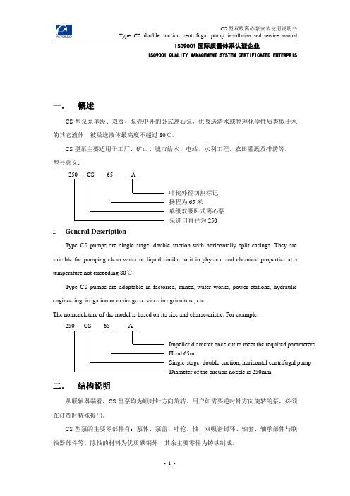
ISO9001国际质量体系认证企业ISO9001 QUALITY MANAGEMENT SYSTEM CERTIFICATED ENTERPRIS一.概述CS型泵系单级、双级、泵壳中开的卧式离心泵,供吸送清水或物理化学性质类似于水的其它液体,被吸送液体最高度不超过80℃。
CS型泵主要适用于工厂、矿山、城市给水、电站、水利工程、农田灌溉及排涝等。
型号意义:250 CS 65 A叶轮外径切割标记扬程为65米单级双吸卧式离心泵泵进口直径为250I.General DescriptionType CS pumps are single stage, double suction with horizontally split casings. They are suitable for pumping clean water or liquid similar to it in physical and chemical properties at a temperature not exceeding 80℃.Type CS pumps are adoptable in factories, mines, water works, power stations, hydraulic engineering, irrigation or drainage services in agriculture, etc.The nomenclature of the model is based on its size and characteristic. For example:250 CS 65 AImpeller diameter once cut to meet the required parametersHead 65mSingle-stage, double-suction, horizontal centrifugal pumpDiameter of the suction nozzle is 250mm二.结构说明从联轴器端看,CS型泵均为顺时针方向旋转。
G6K-2P中文资料

1.Relay functionNone:Single-side stable modelU:Single-winding latching model 2.Contact form2:DPDTF:Outside-L surface mounting terminalG:Inside-L surface mounting terminalP:PCB terminal4.Approved standardsNone:UL, CSADoes not conform to Telcordia specifications Y:UL, CSAConforms to Telcordia specifications: 2,500 V for 2 x10 µs5.Rated Coil Voltage3, 4.5, 5, 12, 24 VDCRC9192Application ExamplesT elephones, communications equipment, measurement devices, office automation machines, and audio–visual products.SpecificationsContact mechanism:Bifurcated crossbar Ag (Au-alloy contact)Enclosure ratings:Fully sealed ■Coil RatingsSingle-side Stable ModelsG6K-2F, G6K-2G, G6K-2P Note:1.The rated current and coil resistance are measured at a coil temperature of 23°C with a tolerance of ±10%.2.The operating characteristics are measured at a coil temperature of 23°C.3.The maximum voltage is the highest voltage that can be imposed on the relay coil instantaneously.Single-side Stable Models (Bellcore Version)G6K-2F-Y, G6K-2G-Y, G6K-2P-Y Note:1.The rated current and coil resistance are measured at a coil temperature of 23°C with a tolerance of ±10%.2.The operating characteristics are measured at a coil temperature of 23°C.3.The maximum voltage is the highest voltage that can be imposed on the relay coil instantaneously.Single-winding Latching Models (Bellcore Version)G6KU-2F-Y, G6KU-2G-Y, G6KU-2P-Y Note:1.The rated current and coil resistance are measured at a coil temperature of 23°C with a tolerance of ±10%.2.The operating characteristics are measured at a coil temperature of 23°C.3.The maximum voltage is the highest voltage that can be imposed on the relay coil instantaneously.Rated voltage 3 VDC 4.5 VDC 5 VDC 12 VDC Rated current 33.0 mA 23.2 mA 21.1 mA 9.1 mA Coil resistance 91 Ω194 Ω237 Ω1,315 ΩMust operate voltage 80% max. of rated voltage Must release voltage 10% min. of rated voltageMax. voltage 150% of rated voltage at 23°C to 70°C Power consumption Approx. 100 mWRated voltage 3 VDC 4.5 VDC 5 VDC 12 VDC 24 VDC Rated current 33.0 mA 23.2 mA 21.1 mA 9.1 mA 4.6 mA Coil resistance 91 Ω194 Ω237 Ω1,315 Ω5,220 ΩMust operate voltage 80% max. of rated voltage Must release voltage 10% min. of rated voltageMax. voltage 150% of rated voltage at 23°C to 70°C Power consumption Approx. 100 mWRated voltage 3 VDC 4.5 VDC 5 VDC 12 VDC 24 VDC Rated current 33.0 mA 23.2 mA 21.1 mA 9.1 mA 4.6 mA Coil resistance 91 Ω194 Ω237 Ω1,315 Ω5,220 ΩMust set voltage 75% max. of rated voltage Must reset voltage 75% max. of rated voltageMax. voltage 150% of rated voltage at 23°C to 70°C Power consumption Approx. 100 mW93■Contact Ratings■CharacteristicsNote:The above values are initial values.Note:1.The contact resistance was measured with 10 mA at 1 VDC with a voltage-drop method.2.Values in parentheses are actual values.3.The insulation resistance was measured with a 500-VDC megohmmeter applied to the same parts as those used for checking the dielectric strength.4.This value was measured at a switching frequency of 120 operations/min and the criterion of contact resistance is 50 Ω. This value may vary depending on the switching frequency and operating environment. Always double-check relay suitability under actual operating conditions.Load Resistive loadRated load0.3 A at 125 VAC; 1 A at 30 VDC Rated carry current 1 AMax. switching voltage 125 VAC, 60 VDC Max. switching current 1 AItemSingle-side stable models (double-pole)Single-winding latchingmodel G6K-2F, G6K-2G, G6K-2PG6K-2F-Y, G6K-2G-Y,G6K-2P-YG6KU-2F-Y, G6KU-2G-Y,G6KU-2P-Y Contact resistance (See note 1.)100 m Ω max.Operating (set) time (See note 2.) 3 ms max. (approx. 1.4 ms) 3 ms max. (approx. 1.2 ms)Release (reset) time (See note 2.) 3 ms max. (approx. 1.3 ms) 3 ms max. (approx. 1.2 ms)Insulation resistance (See note 3.)1,000 M Ω min. (at 500 VDC)Dielectric strengthCoil and contacts1,500 VAC, 50/60 Hz for 1 minContacts of different polarity1,000 VAC, 50/60 Hz for 1 min Contacts of same po-larity750 VAC, 50/60 Hz for 1 min Impulse withstand voltageCoil and contacts1,500 V (10 x 160 µs)2,500 V (2 x 10 µs), 1,500 V (10 x 160 µs)Contacts of different polarity1,500 V (10 x 160 µs)Contacts of same po-larityVibration resistanceDestruction: 10 to 55 Hz, 2.5-mm single amplitude (5-mm double amplitude) and 55 to 500 Hz, 300 m/s 2 (approx. 30G)Malfunction: 10 to 55 Hz, 1.65-mm single amplitude (3.3-mm double amplitude) and 55 to 500 Hz, 200 m/s 2 (approx. 20G)Shock resistance Destruction: 1,000 ms 2 (approx. 100G)Malfunction: 750 ms 2 (approx. 75G)EnduranceMechanical: 50,000,000 operations min. (at 36,000 operations/hour)Electrical: 100,000 operations min. (with a rated load at 1,800 operations/hour)Failure rate (P level) (See note 4.)10 µA at 10 mVDCAmbient temperature Operating: −40°C to 70°C (with no icing or condensation)Ambient humidity Operating: 5% to 85%Weight Approx. 0.7 g94Engineering DataMaximum Switching PowerAmbient Temperature vs. Maximum Coil Voltage Ambient Temperature vs. Switching CurrentS w i t c h i n g c u r r e n t (A )M a x i m u m c o i l v o l t a g e (%)S w i t c h i n g c u r r e n t (A )DC resistive loadSwitching voltage (V)Ambient temperature (°C)Ambient temperature (°C)AC resistive loadNote: The maximum coil voltage refers to the maximum value in a varying range of operating power voltage, not a continuous voltage.EnduranceAmbient Temperature vs. MustOperate or Must Release VoltageG6K-2G (F/P), G6K-2G (F/P)-YS w i t c h i n g o p e r a t i o n s (x 10 o p e r a t i o n s )O n t h e b a s i s o f r a t e d v o l t a g e (%)Switching current (A)125 VAC resistive loadAmbient temperature: 23°C Switching frequency: 1,800 operations/hourAmbient temperature (°C)430 VDC resistive loadAmbient temperature: 23°C Switching frequency: 1,800 operations/hourMax. estimated valueMust operate voltage Must release voltageAmbient Temperature vs. Must Set or Must Reset VoltageG6KU-2G (F/P)-YO n t h e b a s i s o f r a t e d v o l t a g e (%)Ambient temperature (°C)Max. estimated valueElectrical Endurance(with Must Operate and Must Re lease Voltage) (See note.)G6K-2G (F/P), G6K-2G (F/P)-YElectrical Endurance(Contact Resistance) (See note.)G6K-2G (F/P), G6K-2G (F/P)-YC o n t a c t r e s i s t a n c e (m Ω)Operating frequency (x10 operations)O n t h e b a s i s o f r a t e d v o l t a g e (%)Operating frequency (x103operations)Must operateMust releaseSample: G6K-2GSample: G6K-2GT est conditions: 1 A resistive loadNO contact NC contactContact resistanceShock MalfunctionEnergizedNotenergizedShock directionUnit: m/s Sample: G6K-2GNumber of Relays: 10Conditions: Shock is applied in ±X, ±Y , and ±Z directions three times each with and with out energizing the Relays to check the number of contact malfunctions.32Switching frequency: 1,800 operations/hNumber of Relays: 10T est conditions: 1 A resistive load at 30 VDC with an operation rate of 50%Number of Relays: 10at 30 VDC with an operation rate of 50%Switching frequency: 1,800 operations/hNote: The tests were conducted at anambient temperature of 23˚C.Note: The tests were conducted at anambient temperature of 23˚C.95Note:1.The tests were conducted at an ambient temperature of 23°C.2.High-frequency characteristics depend on the PCB to which the Relay is mounted. Always check these characteristics including endurance in the actual machine before use.Sample Not energizedSample EnergizedMust operate voltage Must release voltageInitial stage T estAverage value Initial stageT estAverage valueSampleNot energizedSampleEnergizedInitial stageT estAverage value Initial stageT estAverage valueC h a n g e r a t e o n t h e b a s i so f i n i t i a l v a l u e (%)C h a n g e r a t e o n t h e b a s i s o f i n i t i a l v a l u e (%)C h a n g e r a t e o n t h e b a s i s o f i n i t i a l v a l u e (%)C h a n g e r a t e o n t h e b a s i s o f i n i t i a l v a l u e (%)Must operate voltage Must release voltageOperating frequency (x10 operations)Sample: G6K-2GNumber of Relays: 10T est conditions: 10 mA resistive load at 10 mVDC with an operation rate of 50 %Switching frequency: 7,200 operations/hC o n t a c t r e s i s t a n c e (m )ΩNO contact NC contact(Average value)C h a n g e r a t e o n t h e b a s i s o f i n i t i a l v a l u e (%Sample: G6K-2GNumber of Relays: 10Must operate voltage Must release voltageExternal magnetic field (A/m)(Average value)C h a n g e r a t e o n t h e b a s i s o f i n i t i a l v a l u e (%Sample: G6K-2GNumber of Relays: 10Must operate voltage Must release voltageExternal magnetic field (A/m)(Average value)C h a n g e r a t e o n t h e b a s i s o f i n i t i a l v a l u e (%Sample: G6K-2GNumber of Relays: 10External magnetic field (A/m)Must operate voltage Must release voltage396DimensionsNote:All units are in millimeters unless otherwise indicated.■DPDTG6K-2G (F/P), G6K-2G (F/P)-YN u m b e r o f c o n t a c t sSample: G6K-2GNumber of Relays: 50Time (ms)Sample: G6K-2GNumber of Relays: 50a n g e r a t e o n t h eb a s i s o f r a t e d v a l u e (%After testG6K-2G (F/P) , G6K-2G (F/P)-YN u m b e r o f c o n t a c t sMust operate bounce time Must operate voltage Must release voltageTime (ms)Must release bounce timeMust operate Must release timeG6K-2FMounting Dimensions (Top View)Terminal Arrangement/Internal Connections (Top View)Orientation markNote: Each value has a tolerance of ±0.3 mm.G6K-2GMounting Dimensions (Top View)Terminal Arrangement/Internal Connections (Top View)Orientation markNote: Each value has a tolerance of ±0.3 mm.Tolerance: ±0.1 mmTolerance: ±0.1 mmG6K-2PMounting Dimensions (Bottom View)Terminal Arrangement/Internal Connections(Bottom View)Orientation markNote: Each value has a tolerance of ±0.3 mm.Eight, 0.8-dia. holesTolerance: ±0.1 mmG6K-2F-Y G6K-2G-Y G6K-2P-YMounting Dimensions (Top View)Terminal Arrangement/Internal Connections(Top View)Orientation mark Note: Each value has a tolerance of ±0.3 mm.Mounting Dimensions (Top View)Terminal Arrangement/Internal Connections(Top View)Orientation mark Note: Each value has a tolerance of ±0.3 mm.Tolerance: ±0.1 mmTolerance: ±0.1 mmMounting Dimensions (Bottom View)Terminal Arrangement/Internal Connections(Bottom View)Orientation mark Note: Each value has a tolerance of ±0.3 mm.Eight,0.8-dia. holesTolerance: ±0.1 mmG6KU-2F-Y G6KU-2G-Y G6KU-2P-YMounting Dimensions (Top View)Terminal Arrangement/Internal Connections(Top View)Orientation mark Note: Each value has a tolerance of ±0.3 mm.Mounting Dimensions (Top View)Terminal Arrangement/Internal Connections(Top View)Orientation mark Note: Each value has a tolerance of ±0.3 mm.Tolerance: ±0.1 mmTolerance: ±0.1 mmMounting Dimensions (Bottom View)Terminal Arrangement/Internal Connections(Bottom View)Orientation mark Note: Each value has a tolerance of ±0.3 mm.Eight, 0.8-dia. holesTolerance: ±0.1 mm9798Stick Packing and Tape PackingStick PackingRelays in stick packing are arranged so that the orientation mark of each Relay in on the left side. Fifty Relays are packed on one stick.Be sure not to make mistakes in Relay orientation when mounting the Relay to the PCB.Stick length: 520 mm (stopper not included)No. of Relays per stick: 50Tape Packing (Surface Mounting Terminal Models)When ordering Relays in tape packing, add the prefix “-TR” to the model number, otherwise the Relays in stick packing will be pro-vided.T ape Type:ETX7200(EIAJ (Electronic Industrial Association of Japan))Reel type:RPM-16D (EIAJ)Relays per Reel: 900Stopper (gray)Orientation of RelaysStopper (green)1. Direction of Relay Insertion2. Reel Dimensions3. Carrier Tape DimensionsT op tape (cover tape)Carrier tapePulling directionOrientation markPulling directionG6K-2F , G6K-2F-Y , G6KU-2F-YG6K-2G, G6K-2G-Y , G6KU-2G-YEmboss tape99Recommended Soldering MethodT emperature indicate the surface temperature of the PCBs.IRS Method (for surface mounting terminal models)(1) IRS Method (Mounting Solder: Lead)(2) IRS Method (Mounting Solder: Lead-free)••In order to perform correct soldering, it is recommended that the correct soldering conditions be maintained as shown below on the left side.Visually check that the Relay is properly soldered.■Approved StandardsUL approval:UL1950 (File No. E41515)CSA approval:C22.2 No. 950 (File No. LR31928)T e m p e r a t u r e (°C )SolderingPreheatingTime (s)220 to 245180 to 20015090 to 12020 to 30Contact form Coil ratingContact ratingNumber of test operations DPDTG6K-2G(F/P): 3 to 12 VDCG6K(U)-2G(F/P)-Y: 3 to 24 VDC1 A at 30 VDC 0.5 A at 60 VDC 0.3 A at 125 VAC6,000Correct SolderingIncorrect SolderingPCBT erminalSolder Relay LandExcessive amount of solderInsufficient amount of solderPrecautionsRefer to page25 for information on general precautions. Be sure to read these precautions before using the Relay.Correct UseLong-term Continuously ON ContactsUsing the Relay in a circuit where the Relay will be ON continu-ously for long periods (without switching) can lead to unstable contacts because the heat generated by the coil itself will affect the insulation, causing a film to develop on the contact surfaces. We recommend using a latching relay (magnetic-holding relay) in this kind of circuit. If a single-side stable model must be used in this kind of circuit, we recommend using a fail-safe circuit design that provides protection against contact failure or coil burnout. Relay HandlingUse the Relay as soon as possible after opening the moisture-proof package. If the Relay is left for a long time after opening the moisture-proof package, the appearance may suffer and seal fail-ure may occur after the solder mounting process. To store the Relay after opening the moisture-proof package, place it into the original package and sealed the package with adhesive tape. When washing the product after soldering the Relay to a PCB, use a water-based solvent or alcohol-based solvent, and keep the solvent temperature to less than 40°C. Do not put the Relay in a cold cleaning bath immediately after soldering.SolderingSoldering temperature: Approx. 250°C (260°C if the DWS method is used)Soldering time: Approx. 5 s max. (approx. 2 s for the first time and approx. 3 s for the second time if the DWS method is used)Be sure to adjust the level of the molten solder so that the solder will not overflow onto the PCB.Claw Securing Force During Automatic MountingDuring automatic insertion of Relays, make sure to set the secur-ing force of each claw to the following so that the Relays charac-teristics will be maintained.Environmental Conditions During Operation, Storage, and TransportationProtect the Relay from direct sunlight and keep the Relay under normal temperature, humidity, and pressure.If the Relay is stored for a long time in an adverse environment with high temperature, high humidity, organic gases, or sulfide gases, sulfide or oxide films will form on the contact surfaces. These films may result in unstable contact, contact problems, or functional problems. Therefore, operate, store, or transport the product under specified environmental tching Relay MountingMake sure that the vibration or shock that is generated from other devices, such as relays in operation, on the same panel and imposed on the Latching Relay does not exceed the rated value, otherwise the Latching Relay that has been set may be reset or vice versa. The Latching Relay is reset before shipping. If exces-sive vibration or shock is imposed, however, the Latching Relay may be set accidentally. Be sure to apply a reset signal before use.Maximum Allowable VoltageThe maximum allowable voltage of the coil can be obtained from the coil temperature increase and the heat-resisting temperature of coil insulating sheath material. (Exceeding the heat-resisting temperature may result in burning or short-circuiting.) The maxi-mum allowable voltage also involves important restrictions which include the following:•Must not cause thermal changes in or deterioration of the insu-lating material.•Must not cause damage to other control devices.•Must not cause any harmful effect on people.•Must not cause fire.Therefore, be sure to use the maximum allowable voltage beyond the value specified in the catalog.As a rule, the rated voltage must be applied to the coil. A voltage exceeding the rated value, however, can be applied to the coil provided that the voltage is less than the maximum allowable volt-age. It must be noted that continuous voltage application to the coil will cause a coil temperature increase thus affecting charac-teristics such as electrical life and resulting in the deterioration of coil insulation.CoatingThe Relay mounted on the PCB may be coated or washed but do not apply silicone coating or detergent containing silicone, other-wise the silicone coating or detergent may remain on the surface of the Relay.PCB MountingIf two or more Relays are closely mounted with the long sides of the Relays facing each other and soldering is performed with infrared radiation, the solder may not be properly exposed to the infrared rays. Be sure to keep the proper distance between adja-cent Relays as shown below.Two or more Relays may be closely mounted with the short sides of the Relays facing each other.Direction A: 1.96 NDirection B: 4.90 NDirection C: 1.96 NG6K-2GG6K-2F2 mm min.2.7 mm min.ALL DIMENSIONS SHOWN ARE IN MILLIMETERS.To convert millimeters into inches, multiply by 0.03937. T o convert grams into ounces, multiply by 0.03527. Cat. No. K106-E1-04100。
CRAS2U3CP6G中文说明书PDF版

・操作系统 Windows 8/Windows 7/Windows Vista……………………………… 附注2 ・操作系统 Windows XP……………………………………………………………………………………………………附注13 ●在 Mac OS 使用方法… ……………………………………………………附注14
本产品无法做为操作系统的启动设备。
SATA HDD/SSD使用方法
在未使用时本产品时,请将硬盘取下另外保管。 SATA HDD/SSD制造商对于硬盘连接口(connector)的有一定次数的保证,为避免硬盘的损 坏请在制造商保证范围次数内使用。
※ "经本公司测试,可以正常使用4TB HDD(2013年12月)"最新的硬盘支持情况请咨询客户支持中心。 另,Windows XP的操作系统限制硬盘容量不超过2TB(2TB以上的硬盘在Windows Vista/7/8, 苹果操作系统可以 正常使用,非本产品限制)。 ※不适用SAS(Serial Atached SCSI)HDD。 ※不适用3.3V驱动的HDD。
・连接硬盘时:蓝灯点亮 ・硬盘读取时:红灯闪烁
③ 开始按键
・克隆模式时,按下按键可开始拷贝。
④ 模式切换按键
・长按可切换PC模式/克隆模式
⑤ 工作模式指示灯
・PC模式:蓝灯点亮 ・克隆模式:红灯点亮
⑥ 拷贝进度指示灯
克隆模式时,指示灯的点亮与熄灭表示进度。
3
〈CRAS2U3CP6G〉
【使用前注意事项】
・ 关于本说明书之内容未来若有变更,恕不另行通知。 但若发现有不实的地方还请与本公司的客户支技中心联络。 ・Windows是Microsoft corporation的注册商标。 ・Mac 是 Apple Inc.的注册商标。 ・内容记载的各商品及各产品,公司名皆为各公司的注册商标。 ・产品以实物为准。 ・可能会有机种功能改良而变更规格的情况,不再另行通知。
9926a中文手册
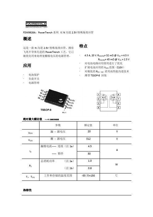
图九最大安全工作区。图十单脉冲最大功率损耗
图十一瞬态热响应曲线
(热特性使用注1b中所描述的条件进行。
瞬态热响应发生变化,这取决于电路板的设计。)
-----暂停
4.5
A
30
PD
总消耗功率(注1a)
(注1b)
1.0
W
0.6
TJ,TSTG
工作和存储的温度范围
-55到+150
℃
热特性
RθJA
热阻,接面至环境(注1a)
(注1b)
125
℃/W
208
封装标志与订购信息
器件标号
器件
卷轴尺寸
胶带宽度
数量
9926A
FDW9926A
13”
12mm
3000单位
电气特性TA=25℃除非另有说明
应用电源管理特点扩展电池应用的vgss范围10v对极低的rdson采用高性能沟道技术薄型tssop8封装绝对最大额定值ta25除非另有说明参数额定值单位源电压20源电压12漏极电流连续注1a暂停45总消耗功率注1a注1b10stg工作和存储的温度范围55到150ja热阻接面至环境注1a注1b125208封装标志与订购信息器件标号器件卷轴尺寸胶带宽度数量9926afdw9926a1312mm3000单位电气特性ta25除非另有说明信号参数测试环境最小值典型值最大值单位关闭特性bvdss漏源击穿电压vgsbvdss25c12mvdss零栅电压漏电流gss栅极基极漏电流100na开启特性注vgsth栅极阈值电压vdsvgsid061015dvgsthtj栅极阈值电压温度系数idreferencedmvcrdson静态漏源导通电阻vgs45atj125243433324548idon使用状态漏电流vgsgfs正向跨导vds动态特性ciss输入电容vds10mhz630pfcoss输出电容150pfcrss反向传输电容85pfrg栅电阻vgs15mv10mhz14tdon开启延迟时间vdd16nstr开启上升时间16nstdoff关闭延迟时间15nstf关断下降时间nsqg总栅极电荷vdsncqgs栅源电荷11ncqgd栅漏电荷18nc漏源二极管的特性和最大额定值最大连续漏源极电流083vsd漏源二极管的正向电压vgs06912trr二极管的反向恢复时间nsqrr二极管反向恢复电荷当热参考被定义为漏极引脚的焊锡的安装表面rja是接面至外壳接面至环境热阻的总和
兔子ELISA试剂盒说明书,碱性成纤维细胞生长因子ELISA试剂盒

兔子ELISA试剂盒说明书,碱性成纤维细胞生长因子ELISA试剂盒兔子ELISA试剂盒说明书,碱性成纤维细胞生长因子ELISA试剂盒产品规格:96T/48T用途:科研实验等领域科学研究,不得用于临床诊断。
供应商:上海樊克生物有限公司兔子ELISA试剂盒说明书,碱性成纤维细胞生长因子ELISA试剂盒Elisa kit test rules:1, to ensure the accuracy of the pipette, the error can not be more than 2%. To determine the available water and electronic balance. But the best professional correction. 2, to be equipped with 20ul, 50ul, 100ul, 1000ul and a volley. Use of different liquids, to replace the gun head. That is to learn standard.3, in the 1 hours before the experiment the kit from the refrigerator, make all kinds of reagents are restored to room temperature, in order to make the results more stable.4, the experiment, to make the substrate away from light.5, used a gun to suck the liquid when the speed is not too fast, so as to avoid air bubbles and the suction amount is not accurate.6, learn to use liquid, and close to the gun range need to suck, reduce the error. 7, when the liquid is added to the enzyme standard hole, the liquid contact of the liquid drop and the hole wall of the gun head can be avoided by avoiding the contact of the liquid drop and the hole wall in the gun head.8, after all the liquid added, the enzyme labeled plate on the table in parallel to gently shake 30 seconds, mixed with liquid. Can also use the shaking function of the enzyme standard instrument.9, should try to do two experiments, so as to ensure the accuracy of the data. 10, the results have questions about the sample to be confirmed by other methods兔子ELISA试剂盒说明书,碱性成纤维细胞生长因子ELISA试剂盒兔子ELISA试剂盒说明书,碱性成纤维细胞生长因子ELISA试剂盒试剂盒组成:封板膜:2片(48)/2片(96)说明书:1份密封袋:1个标准品:???2700ng/L 0.5ml×1瓶 0.5ml×1瓶??2-8℃保存酶标包被板:??1×48 ????1×96 ????????2-8℃保存样品稀释液:?3ml×1瓶? 6?ml×1瓶 ????2-8℃保存显色剂A液:?3ml×1瓶 6?ml×1瓶 ????2-8℃保存显色剂B液:?3ml×1瓶 6?ml×1瓶 ????2-8℃保存终止液:?????3ml×1瓶 6ml×1瓶 ????2-8℃保存浓缩洗涤液:(20ml×20倍)×1瓶(20ml×30倍)×1瓶???2-8℃保存兔子ELISA试剂盒说明书,碱性成纤维细胞生长因子ELISA试剂盒Elisa kit test rules:1, to ensure the accuracy of the gun, the error can not be more than 2%. Available water and electronic balances are determined. But it's better to have professional personnel to correct it.2, to be equipped with 20ul, 50ul, 100ul, 1000ul and a volley. Draw different liquids, to replace the gun head. Even when the standard is drawn.1, 3 hours before the experiment to remove the kit from the refrigerator, so that a variety of reagents are restored to room temperature, in order to make the results more stable.4, the experiment, to make the substrate to avoid light storage.5, with the gun to draw the liquid speed can not be too fast, so as not to produce bubbles and to absorb the amount is not accurate.6, when the liquid, to use the range and the need to close the gun to suck, reduce the error.7, when the liquid is added to the enzyme standard hole, the liquid contact of the liquid drop and the hole wall of the gun head can be avoided by avoiding the contact of the liquid drop and the hole wall in the gun head.8, after all the liquid added, the enzyme labeled plate on the table in parallel to gently shake 30 seconds, mixed with liquid. Can also use the shaking function of the enzyme standard instrument.9, should try to do two experiments, so as to ensure the accuracy of the data. 10, the results have questions about the sample to be confirmed by other methods.兔子ELISA试剂盒说明书,碱性成纤维细胞生长因子ELISA试剂盒试剂盒性能1. 灵敏度:最小的浓度小于1号标准品。
3KC ATC6300 自动转换控制器 设备手册说明书
4.5 4.5.1 4.5.2
ATC6300 的显示页面....................................................................................................30 显示页面说明 ...............................................................................................................30 滚动显示页面 ...............................................................................................................41
2.1
ATC6300 自动转换控制器的属性 ..................................................................................15
2.2
兼容的西门子 SENTRON 开关设备.................................................................................17
3.3
电压控制 ......................................................................................................................22
4 产品描述 .........................................................................................................................................25
重组人神经生长因子对糖尿病大鼠难愈创面愈合的影响
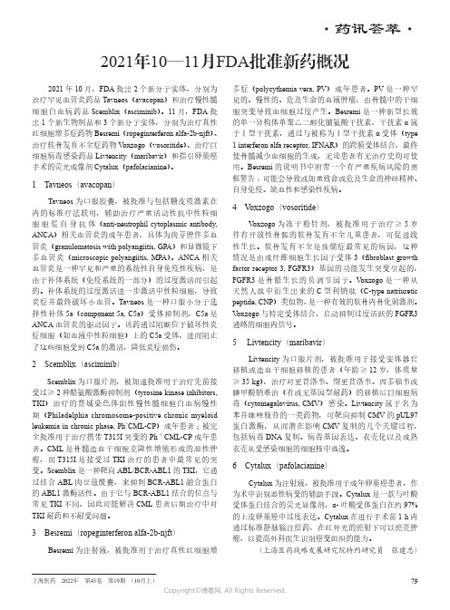
中国药理学通报Chinese Pharmacological Bulletin,2019Jun;35(6):793〜6-793-网络出版时间:2019-5-917:24网络出版地址:http:///kcms/detail/34.1086.R.20190507.1517.024.html 重组人神经生长因子对糖尿病大鼠难愈创面愈合的影响王甜甜",程玉芳3,徐江平V(南方医科大学1.药学院神经药理与新药发现学科、2.药学院广东省新药筛选重点实验室、3.中心实验室,广东广州510515)doi:10.3969/j.issn.1001-1978.2019.06.012文献标志码:A文章编号:1001-1978(2019)06-0793-04中国图书分类号:R-332;R322.99;R364.16;R587.1;R644;R977.6摘要:目的研究重组人神经生长因子(recombinant human nerve growth factor,rhNGF)对糖尿病大鼠合并d愈创面的治疗效果。
方法腹腔注射链眼佐菌素(60mg-kg-1)诱导大鼠糖尿病模型,并在大鼠背部造成一圆形烫伤创面,建立糖尿病合并d愈创面的动物模型。
用药组rhNGF(3、6、12憾-kg")肌肉注射给药,每天1次,连续21d。
测定大鼠伤口面积,HE染色和透射电镜检查创面皮肤组织病理形态学变化。
结果rhNGF明显减小糖尿病大鼠烫伤创伤面积(P< 0.05);HE染色结果表明,rhNGF明显促进糖尿病大鼠烫伤创面纤维细胞和毛细血管再生;透射电镜结果表明,rhNGF 对糖尿病大鼠烫伤创面皮肤的上皮细胞结构排列、细胞连接以及上皮下胶原等超微结构有明显改善作用。
结论rhNGF对糖尿病大鼠烫伤性d愈创面具有促进愈合的作用。
关键词:重组人神经生长因子;链眼佐菌素;糖尿病;大鼠;溃疡;创面愈合难愈性溃疡(又称难愈创面)是糖尿病的主要并发症之一「"o据报道,超过15%的糖尿病患者存在足部溃疡,严重者甚至导致截肢⑷,给患者带来巨大的精神压力,严重影响患者生活质量,同时也给患者造成了繁重的经济负担03-41o因此,糖尿病难愈溃疡是亟待解决的重大问题之一o据报道,神经分布异常和神经炎症是造成糖尿病难愈创面的原因之一,并伴随皮肤创面中神经数量减少,神经生长因子(nerve growth factor,NGF)减收稿日期:2019-01-20,修回日期:2019-03-10革金项目:国家自然科学革金资助项目(No81773698);广东省科技计划(No2015B020211007);广州市科技计划(No201604020112)作者简介:王甜甜(1994-),女,硕士生,研究方向:神经药理学与新药临床前研究,E-mail:ttwang0710@;徐江平(1967-),男,博士,教授,博士生导师,研究方向:神经药理学与新药临床前研究,通讯作者,E-mail:jpx@ 少「5NGF是最先被发掘的神经营养因子,其在调节交感神经和感觉神经细胞的发育和维持方面起着不可替代的作n,对于创面愈合具有重要意义「6-'1o 前期研究发现,鼠神经生长因子(mouse nerve growth factor,mNGF)对糖尿病大鼠皮肤损伤有促进愈合的作ffl06,91o与mNGF相比,重组人神经生长因子(recombinant human nerve growth factor,rhNGF)与人神经生长因子(human nerve growth factor,hNGF)同源性更高,生产规模不受动物原料的限制,而且不存在动物源致病性病毒污染的威胁,具有较大的发展潜力。
2021年10—11月FDA批准新药概况
上海医药 2022年 第43卷 第19期 (10月上)·药讯荟萃·2021年10—11月FDA批准新药概况2021年10月,FDA批出2个新分子实体,分别为治疗罕见血管炎药品Tavneos(avacopan)和治疗慢性髓细胞白血病药品Scemblix(asciminib)。
11月,FDA批出1个新生物制品和3个新分子实体,分别为治疗真性红细胞增多症药物Besremi(ropeginterferon alfa-2b-njft)、治疗软骨发育不全症药物V oxzogo(vosoritide)、治疗巨细胞病毒感染药品Livtencity(maribavir)和指引卵巢癌手术的荧光成像剂Cytalux(pafolacianine)。
1 Tavneos(avacopan)Tavneos为口服胶囊,被批准与包括糖皮质激素在内的标准疗法联用,辅助治疗严重活动性抗中性粒细胞胞浆自身抗体(anti-neutrophil cytoplasmic antibody, ANCA)相关血管炎的成年患者,具体为肉芽肿伴多血管炎(granulomatosis with polyangiitis, GPA)和显微镜下多血管炎(microscopic polyangiitis, MPA)。
ANCA相关血管炎是一种罕见和严重的系统性自身免疫性疾病,是由于补体系统(免疫系统的一部分)的过度激活而引起的。
补体系统的过度激活进一步激活中性粒细胞,导致炎症并最终破坏小血管。
Tavneos是一种口服小分子选择性补体5a(component 5a, C5a)受体抑制剂,C5a是ANCA血管炎的驱动因子。
该药通过阻断位于破坏性炎症细胞(如血液中性粒细胞)上的C5a受体,进而阻止了这些细胞受到C5a的激活,降低炎症损伤。
2 Scemblix(asciminib)Scemblix为口服片剂,被加速批准用于治疗先前接受过≥2种酪氨酸激酶抑制剂(tyrosine kinase inhibitors, TKI)治疗的费城染色体阳性慢性髓细胞白血病慢性期(Philadelphia chromosome-positive chronic myeloid leukemia in chronic phase, Ph+CML-CP)成年患者;被完全批准用于治疗携带T315I突变的Ph+CML-CP成年患者。