fluidflow
化工单元操作英文教材-流体流动现象Fluid-flow phenomena

Bingham plastic
The rheological behavior of liquids called non-Newtonian.
o
du/dy
Figure 3 Shear stress versus velocity gradient for non-Newtonian fluids.
turbulent flow: The fluid moves erratically in form of crosscurrents and eddies.
Gas :
kinematic viscosities increase more rapidly with temperature than does the absolute viscosity.
Turbulence
It has long been known that a fluid can flow through a pipe or conduit in two different ways:
One-dimensional flow
Velocity is a vector, but only one velocity component is required. This simple situation is called Onedimensional flow.
Example: steady flow through straight pipe.
The assumptions of steady one-dimensional flow is the basis of following discussion. All we will talk about in this course belong to one dimensional steady flow
流体力学中英文术语

流体力学中英文术语Index 翻译(Fluid Mechanics)Absolute pressure,绝对压力(压强)Absolute temperature scales, 绝对温标Absolute viscosity, 绝对粘度Acceleration加速度centripetal, 向心的convective, 对流的Coriolis, 科氏的field of a fluid, 流场force and,作用力与……local, 局部的Uniform linear, 均一线性的Acceleration field加速度场Ackeret theory, 阿克莱特定理Active flow control, 主动流动控制Actuator disk, 促动盘Added mass, 附加质量Adiabatic flow绝热流with friction,考虑摩擦的isentropic,等熵的air, 气体with area changes, 伴有空间转换Bemoullii’s equation and, 伯努利方程Mach number relations,马赫数关系式,pressure and density relations, 压力-速度关系式sonic point,critical values, 音速点,临界值,stagnation enthalpy, 滞止焓Adiabatic processes, 绝热过程Adiabatic relations, 绝热关系Adverse pressure gradient, 逆压力梯度Aerodynamic forces, on road vehicles, 交通工具,空气动力Aerodynamics, 空气动力学Aeronautics, new trends in, 航空学,新趋势Air空气testing/modeling in, 对……实验/建模useful numbers for, 关于……的有用数字Airbus Industrie, 空中客车产业Aircraft航行器airfoils机翼new designs, 新型设计Airfoils, 翼型aspect ratio (AR), 展弦比cambered, 弧形的drag coefficient of , 阻力系数early, 早期的Kline-Fogleman, 克莱恩-佛莱曼lift coefficient, 升力系数NACA,(美国) 国家航空咨询委员会separation bubble, 分离泡stalls and, 失速stall speed, 失速速度starting vortex, 起动涡stopping vortex, 终止涡Airfoil theory, 翼型理论flat-plate vortex sheet theory, 平板面涡理论Kutta condition, 库塔条件Kutta-Joukowski theorem, 库塔-儒科夫斯基定理1thick cambered airfoils, 厚弧面翼型thin-airfoils, 薄翼型wings of finite span, 有限展宽的翼型A-380 jumbo jet, 大型喷气式客机Alternate states, 交替状态American multiblade farm HA WT, 美式农庄多叶水平轴风机Angle of attack, 攻角Angle valve, 角阀Angular momentum角动量differential equation of , 关于…的微分方程relation/theorem, 联系/理论Annular strips, 环形带Applied forces, linear momentum, 外加力,线性冲力Apron,of a dam, 大坝的护坦Arbitrarily moving/deformable control volume, 任意运动/可变形控制体Arbitrary fixed control volume, 任意固定控制体Arbitrary viscous motion, 随机粘性运动Archimedes, 阿基米德Area changes, isentropic flow. 域变换,等熵流Aspect ratio (AR), 展弦比Automobiles, aerodynamic forces on, 汽车,气动力A verage velocity, 平均速度Axial-flow pumps. 轴流泵Axisymmetric flow, stream function 轴对称流,流函数Axisymmetric Potential flow, 轴对称有势流hydrodynamic mass, 水力学质量Point doublet, 点偶极子point source or sink, 点源与点汇spherical Polar coordinates and, 球极坐标uniform stream in the x direction, x方向的均匀流uniform stream plus a point doublet, 均匀流附加点偶极子uniform stream plus a point source, 均匀流附加点源BBackward-curved impeller blades, 后向曲叶轮片,Backwater curves, 回水曲线Basic equations, non dimensional, 基本方程,无量纲的Bernoulli obstruction theory, 伯努利障碍理论Bernoulli's equation, 伯努利方程with adiabatic and isentropic steady flow, as绝热、等熵稳态流frictionless flow, 无摩擦流assumptions/restrictions for, 假想/约束HGLs and EGLs, 水力坡度线和能量梯度线steady flow energy and, 定常流动能量in rotating coordinates. 在旋转坐标下,Best efficiency point (BEP), pumps, 最佳效率点,Betz number, 贝兹数Bingham plastic idealization, 宾汉塑性理想化,Biological drag reduction, 生物学阻力衰减Blade angle effects, on pump head, 叶片安装角效率,泵头处Blasius equation, 布拉修斯方程Body drag, at high Mach numbers, 机体阻力,在高马赫数下Body forces, 体力Boeing Corp., 波音公司Boundaries, of systems, 边界,系统Boundary conditions. 边界条件,differential relations for fluid flow, 流体的微分关系nondimensionalizalion and, 无量纲化Boundary element method (BEM), 边界元方法2Boundary layer (BL) analysis, 边界层分析boundary layer flows, 边界层流动boundary layer separation on a half body, 边界层半体分离displacement thickness, 位移厚度drag force and, 阻力equations, 方程flat-plate. 平板,Karman's analysis, 卡门分析momentum integral estimates, 动量积分估计momentum integral relation. 动量积分关系momentum integral theory, 动量积分理论pressure gradient 压力梯度separation on a half body, 半模分离skin friction coefficient, 表面摩擦系数two-dimensional flow derivation, 二维流推导Boundary layers with Pressure gradient, 边界层压力梯度adverse gradient, 反梯度favorable gradient, 正梯度laminar integral theory, 层流积分理论,nozzle-diffuser example,喷口扩散算例Bourdon tube, 波登管Bow shock wave, 弓形激波Brake horsepower,制动马力Broad-crested weirs, 宽顶堰Buckingham Pi Theorem, 白金汉定理Bulb Protrusion, 球形突出物(船头)Bulk modulus. 体积模量Buoyancy, 浮力Buoyant particles, local velocity and, 悬浮颗粒,局部速度Buoyant rising light spheres, 浮力作用下自由上升的球体Butterfly valve, 蝶形阀CCambered airfoils, 弓型翼Cauchy-Riemann equations, 柯西-黎曼方程Cavitation/Cavitation number, 气穴/气蚀数Celsius temperature scales, 摄氏温标Center of buoyancy, 浮心Center of Pressure (CP),压力中心,压强中心Centrifugal pumps, 离心泵backward-curved impeller blades, 后曲叶轮片blade angle effects on pump head, 泵头处叶片安装角效率brake horsepower, 制动马力circulation losses, 环量损失closed blades, 闭叶片efficiency of, 效率的elementary pump theory. 基泵理论Euler turbomachine equations, 欧拉涡轮机方程eye of the casing, 泵体通风口friction losses, 摩擦损失hydraulic efficiency, 水力[液压]效率mechanical efficiency.机械效率open blades, 开放式叶片output parameters, 输出参数power, delivered, 功率,传递pump surge, 泵涌,scroll section of casing, 卷形截面,泵体,shock losses, 激波损失vaneless, 无叶片的3volumetric efficiency, 容积效率[系数]water horsepower, 水马力Centripetal acceleration, 向心加速度Channel control Point, 传送控制点Characteristic area. external flows, 特征区域,外流Chezy coefficient, 薛齐系数Chezy formula, 薛齐公式Chezy coefficient,薛齐系数flow in a Partly full circular pipe, 流体非充满的圆管流Manning roughness correlation. 曼宁粗糙度关系,normal depth estimates, 法向深度估计Choking, 壅塞;堵塞of compressors, 压缩机的due to friction, compressible duct and, 由于摩擦,可压缩管的isentropic flow with area changes, 变横截面积等熵流simple heating and, 单纯加热Circular cylinder, flow with circulation. 圆柱体,Circulation环量and flow past circular cylinder, 流体经过圆柱体losses, in centrifugal pumps, 损失,离心泵potential flow and, 有势流Circumferential pumps, 环型泵Classical venturi, 标准文氏管Closed blades, centrifugal pumps. 闭叶片,离心泵Closed-body shapes, 闭体外形,circular cylinder, with circulation, 圆柱体,环量Kelvin oval, 开尔文椭圆,Kutta-Joukowski lift theorem,库塔-儒科夫斯基升力定理,Potential flow analogs, 有势流模拟Rankine oval, 兰金椭圆rotating cylinders. lift and drag, 旋转柱体,升力与阻力Coanda effect, 柯恩达效应( 沿物体表面的高速气流在Cobra P-530 supersonic interceptor, 眼镜蛇超音速拦截机Coefficient matrix. 系数矩阵Coefficient of surface tension, 表面张力系数Coefficient of viscosity, 粘滞系数Commercial CFD codes, viscous flow, 商业的计算流体力学代码,粘流Commercial ducts, roughness values for, 商业管道Composite-flow, open channels, 合成流,开槽道Compressibility, non dimensional. 压缩性,无量纲Compressibility effects, 压缩效果Compressible duct flow with friction, 伴有摩擦的可压缩管流adiabatic, 绝热的, 隔热的choking and, 壅塞;堵塞isothermal flow in long pipelines, 管线中的等温流动,long pipelines, isothermal flow in, 管线,等温流动,mass flow for a given pressure drop, 给定压降下质量流动minor losses in, 最小损失subsonic inlet, choking due to friction, 亚音速进口,摩擦引发阻塞,supersonic inlet, choking due to friction, 超音速进口,摩擦引发阻塞,Compressible flow, 可压缩流flow with friction摩擦流choking and, 壅塞;堵塞converging-diverging nozzles, 拉瓦尔喷管converging nozzles, 收缩喷嘴Fanno flow, 法诺流动,gas flow correction factor, 气流校正参数hypersonic flow, 高超音速气流4incompressible flow, 不可压缩流isentropic.等熵的isentropic Process, 等熵过程,Mach number, 马赫数normal shock wave. 正激波the perfect gas, 理想气体Prandtl-Meyer waves. 普朗特-麦耶膨胀波shock waves. 激波specific-heat ratio, 比热比speed of sound and,声速subsonic, 亚音速的supersonic,超音速的transonic, 跨音速的two-dimensional supersonic, 二维超音速的Compressible gas flow correction factor, 可压缩气流校正因数Compressors, 压缩机Computational fluid dynamics (CFD), 计算流体力学pump simulations, 泵模拟viscous flow. 粘流Concentric annulus, viscous flows in, 同心环Cone flows, 锥体绕流Conformal mapping, 保角映射[变换] Conservation of energy, 能量守恒定律Conservation of mass. 质量守恒定律Consistent units, 相容单元Constants, 常量dimensional, 空间的pure, 纯粹的Constant velocity, fluid flow at, 常速度, 等速度Constructs, 结构Contact angle, 交会角Continuity, 连续性,equation of ,方程nondimensionalization and, 无量纲的Continuum, fluid as, 连续流体Contraction flow, 收缩流动Control Point, channel, 控制点,管道Control volume analysis,控制体分析angular momentum theorem. 角动量定理,arbitrarily moving/deformable CV,任意运动/可变形控制体arbitrarily fixed control volume, 任意固定控制体conservation of mass, 质量守恒定律control volume moving at constant velocity, 控制体以等速运动control volume of constant shape but variable velocity作变速运动的刚性控制体energy equation. 能量方程introductory definitions, 介绍性定义linear momentum equation. 线性动量方程,one-dimensional fixed control volume, 一维固定控制体,one-dimensional flux term approximations, 一维通量项近似Physical laws. 物理定律。
FluidFlow3 最新版教程-QuickStart
Owned and Copyright by Flite Software NI LtdPiping Systems FluidFlowQuick StartTable of ContentsForeword0 Part I Piping Systems FluidFlow1 1Welcome (1) (1)2Installation3Activation (1)4Keeping your Software Current (9)5Network Issues (10)6Starting the Application (Network Module) (13)7Changing User Access Information (Network Module) (15)8Application Layout (17)9Auto Equipment Sizing Example (18)10Design of a Cooling Water System - Part 1 (22)11Design of a Tank Farm Gas Collection System (39)12Design of a Cooling Water System - Part 2. (41)13Configuration and Environment (47) (49)14Databases15Fluids Database (49)16Database of Manually Operated Valves (51) (54)17Add a New PumpIndex561Piping Systems FluidFlow1.1WelcomeWelcome to Piping Systems FluidFlow a state-of-the-art fluid flow simulator. This software application allows you to simulate the flow of fluids in complex networks, taking into account the phase state ofthe fluid and determining heat changes. FluidFlow is more than a pipe network analysis program, it isa fully developed steady-state process-flow simulator.System Requirements1024 MB RAM (2048 MB recommended).All versions of Microsoft Windows & MS Windows Server since 2000.80MB of free hard disk space.SVGA or higher resolution monitor (XGA recommended).Mouse or other pointing device.R e m e m b e r, wh e n co n d u ctin g y o u r e v a lu a tio n o f Flu id Flo w, h e lp is a lwa y s a v a ila b le.Co n ta ct u s with a n y q u e r ie s a t; s u p p o r t@flu id flo win fo.co m. W e wo u ld b e d e lig h te d to h e a r fr o m y o u.1.2InstallationFluidFlow is supplied as a single compressed installation file - FF3SETUP.EXE. This file is available viaa download from our website (preferred method).This is a common installation file for all possible modules. Simply run the file FF3SETUP.EXE and theinstaller will start and take you through the setup process. You can also use the setup program toinstall updates into your installation folder (only executable, help files etc are updated, databasesand your project files are not overwritten).It is possible to install remotely if you are a network administrator. The installation does not requireany registry entries and for users not wishing to use an installer (for example in lockedenvironments) there is a zipped version of the application and associated folders.This product has been fully tested and can also be installed to run under C itrix or Terminal Services.If you intend to run many concurrent users across remote locations outside of a LAN, (i.e. a WANacross country borders) you need to purchase a global licence.Once installed the software reverts to demo mode until it is activated. So the first thing you need todo after installation is to Activate the software. There is a simple activation process for both installed and unzipped installations.In order to activate and run the software you MUST have read/write access to the folder whereFluidFlow is installed. You cannot activate over a LAN or WAN without using terminal services, remote desktop, citrix etc, since for activation the application MUST be running in the server processworkspace. For more information about the activation process see the activation chapter.1.3ActivationWhen you first install FluidFlow, there are no active modules. The software MUST be activated tounlock the calculation modules and the full functionality of the program.There are three methods available to activate the program; 1) License Manager, 2) Website & 3)Email.The steps required for each of these options are outlined below.1) License Manager Activation.Once you have installed FluidFlow, the software must be activated to unlock the full functionality.Activation is the process of configuring access to the available FluidFlow modules. After a newinstallation there are no active modules.From FluidFlow V3.3, the product activation can be carried out automatically. When FluidFlow is started for the first time the following dialog appearsIf you wish to defer activation or do not have an internet connection then press No and you can activate via email or directly from our website. If you have an internet connection then select the Yes button and the activation process will be completed as described below.When you purchase the software or obtain a demo licence you will be provided with a Username and Password. Use the information provided in the Licence Manager as shown.Press the Activate FluidFlow3 button and the software will automatically obtain an activation code and activate the software. If a successful activation occurs the following message appearsAll of the alternative activation methods that were available prior to V3.3 are still available and these are described below.You can use the 'Help | Activate FluidFlow...' menu option, which will display the dialog below.C lick on the "How to Register" tab and select one of the available registration methods.The software generates a Product Id (9DFC-D803 in the example above) directly from your computer. Simply email this Product Id together with the calculation modules you need, or have purchased, to support@ and an activation code and registration name will be provided (usually by return).On receipt of your activation code and registration name (you can specify the registration name if you wish in the email you send to us), click on the "Activate" tab and enter the information you have received as shown below.Assuming we have received the following activation data:Registration Name: Flite Software NI LtdActivation C ode:0A0306A5365AAF07A3F28D3FA20BFB5C7BE5682AB8571C880EBF57FD384AB966A91D7A987EE0338F 7EDFBF57FD384AB966A922ADEA59EF25E4187DBF57FD384AB966A9A3BFF345B0BA0C EAC BAF6A2F9 111094829563E472C E22F9180EFAF6A2F911109482940AF7E349247A69F8BF57FD384AB966A932C C E DC ABF38D8FF4AF6A2F9111094829DBAEB3D1623F8B8BFAF6A2F9111094829256BDC8D142C D1ED6A F6A2F911109482918FF732900F4D7F42AF6A2F91110948291C opy and paste this information from your email.Press the 'Activate FluidFlow' button and the Registration Id will now contain a code instead of Evaluation Version and the modules that you have purchased will become available.If you are activating a network version then you should also read the network activation and setup section for additional information.2) Website Activation.When using the website activation method, we firstly need to visit the FluidFlow website www. and login by selecting the "Login" option (Figure 1) on the top right hand corner of the homepage. Note, this must be completed BEFORE we start the software.Figure 1: Login option available on FluidFlow website.Once you have selected "Login", you will be presented with a new dialogue (Figure 2) where you can enter your customer Username and Password. Note, the Username and Password will be provided separately by the FluidFlow team.Figure 2: Customer Username & Password Login.When you have successfully logged into your account, you can then start FluidFlow. When FluidFlow is running, select; Help | Activate FluidFlow which will display the dialog in Figure 3. Note, a "-1" appears adjacent each module which indicates that the module is not activated.Figure 3: Activate FluidFlow Dialogue (Pre-Activation).Select the 'Activate FluidFlow' button and the software will be automatically activated from the website. Note, once this step is complete, you will need to exit and restart FluidFlow to complete the activation process.At this stage, we recommend when you restart FluidFlow that you select; Help | Activate FluidFlow to check that the activation process has been completed successfully and the correct number of licenses is noted against each calculation module.If the process has been completed successfully, the value of "-1" as shown in Figure 3 will change to display the number of activate licenses. Figure 4 shows a value of "1" adjacent each module which means we have activated one Liquid, Gas, Two-Phase, Slurry & Scripting license. You are now ready to commence modeling.Figure 4: Activate FluidFlow Dialogue (Post-Activation).If you are activating a network version then you should also read the network activation and setup section for additional information.3) Email Activation.If you choose to activate the software by email, please follow the steps outlined below.Start FluidFlow and select: Help | Activate FluidFlow. This will open the dialogue as per Figure 5.Figure 5: Activate FluidFlow Dialogue (Pre-Activation).Email the Product ID to sales@. In the case of Figure 5, the Product ID is 0241-D364. The FluidFlow team will then reply with a Registration Name and Activation Code which you can use to activate the software.C opy and paste the Registration Name and Activation Code into the relevant sections of the "Activate FluidFlow" dialogue box, taking care to ensure there are no spaces between characters of the activation code. Now you can select the "Activate FluidFlow" button and then close the dialogue box.Note, you will need to exit and restart FluidFlow to complete the activation process.At this stage, we recommend when you restart FluidFlow that you select; Help | Activate FluidFlow to check that the activation process has been completed successfully and the correct number of licenses is noted against each calculation module.If the process has been completed successfully, the value of "-1" as shown in Figure 5 will change to display the number of activate licenses. Figure 6 shows a value of "1" adjacent each module which means we have activated one Liquid, Gas, Two-Phase, Slurry & Scripting license. You are now ready to commence modeling.Figure 6: Activate FluidFlow Dialogue (Post-Activation).1.4Keeping your Software CurrentFlite Software has a commitment to constant improvement of the FluidFlow product. In addition weprovide an undertaking to attempt to fix bugs and annoyances in a timely manner. This commitment means that the FluidFlow product is constantly improving and so it is in your interest to stay currentby using the latest release.From Version 3 we have adopted the following numbering convention for product versions.All minor bug fixes for a given version will be implemented via new builds of the same version.This is in contrast to the old system used for V2 product, which always incremented the versionnumber for all bug fixes.Only enhancements or new features will cause a version number increment to occur. For example,in the past any new bugs reported for version 2.26 would be fixed and appear in a 2.27 versiononly. Now, any new bugs reported for version 3.15 Build 1 will be fixed and will appear in version3.15 Build 2. Written as 3.15.2All version numbers have the format [Major Version].[Minor Version] Build Number, for example,3.22 Build 5 means a Version 3 product with a Minor Version number of 22 and a Build Number of5. Written as 3.22.5It is your responsibility to keep your software current via our website. We have a SoftwareAssurance Policy that enables continued access to the downloads area of our website:1.5Network IssuesNote: This section is only relevant if you have the Network module.Network InstallationThe installation process on the network is the same as stand-alone: simply run FF3SETUP.EXE.FluidFlow can be installed across a network as long as you use terminal services, remote desktop, ora similar access method.Im p o r ta n t No te, the network folder MUST have full read/write/create/delete/ access, which usually means you must have admin rights during the installation process. FluidFlow does not use or require access to the Registry.After installation your network users must be given permission/access rights to the FluidFlow folder.We would suggest that users are given full access to the folder that FluidFlow is installed in, e.g.,\Flite\FluidFlow3, and that this access is propagated through the sub-folders.However, if you wish to restrict full access, FluidFlow requires read access to all folders, andadditionally, write access to the following folders:\Flite\FluidFlow3\Flite\FluidFlow3\Data (and all sub-folders)\Flite\FluidFlow3\Preferences (and all sub-folders)Note: In Windows XP, it is not enough to just change the properties of the folder(s), you must alsocheck the 'Allow network users to change my files' checkbox in the Network Sharing and SecurityProperties for the folder. (Note: This can be accessed in Windows Explorer via the Properties context menu item, then the Sharing tab.)Overriding the location of the Read-Write FoldersWith some network installations, Administrators prefer to have control over which folders client users have read-write access to. To cater for this, FluidFlow provides PSFF.INI which allows theAdministrator to specify the default location for \Data, \Preferences, and the Network Access files.Note: FluidFlow does not create this INI file itself; it is the responsibility of the Network Administrator to create PSFF.INI and place it in the same folder as PSFF.EXE. If you wish to use a psff.ini file follow the explanations below;PSFF.INI[Options]; DataUseCommonAppDataFolder=0DataFolder=; PreferencesUseLocalAppDataPreferencesFolder=0PreferencesFolder=; Network AccessUseCommonAppDataNetworkAccessFolder=0NetworkAccessFolder=DataIf UseC ommonAppDataFolder=1 then FluidFlow will use the "C:\Document and Settings\AllUsers\Application Data\FluidFlow3\Data" folder. Otherwise FluidFlow will use the value of theDataFolder entry. If this is blank, or PSFF.INI does not exist, then FluidFlow will use "\FluidFlow3\Data".NOTE: If DataFolder is specified then this folder MUST exist.PreferencesIf UseLocalAppDataPreferencesFolder=1 then FluidFlow will use the "C:\Document andSettings\[Username]\Local Settings\Application Data\FluidFlow3\Preferences" folder. Otherwise FluidFlow will use the value of the PreferencesFolder entry + [Username]. If this is blank, or PSFF.INI does not exist, then FluidFlow will use "\FluidFlow3\Preferences\[Username]". [Username] is the windows log on name of the user.Network AccessIf UseC ommonAppDataNetworkAccessFolder=1 then FluidFlow will use the "C:\Document and Settings\All Users\Application Data\FluidFlow3" folder. Otherwise FluidFlow will use the value of the NetworkAccessFolder entry. If this is blank, or PSFF.INI does not exist, then FluidFlow will use"\FluidFlow3".NOTE: If NetworkAccessFolder is specified then this folder MUST exist.Network ActivationAlthough FluidFlow can be installed across a network, it must be activated from the installation on the server machine. This means you must be either physically at the server or accessing the server remotely via terminal services, citrix etc. You cannot activate the server via normal LAN access. When contacting Flite for an Activation C ode, please state how many users the network license is for.To contact Flite and receive your Activation C ode:Ring Flite on Int+44 2871 279227. You will need to quote your Product Id, specify a Registration Name, and the Modules you require.E-mail salest@. You will need to include your Product Id, a Registration Name, and the Modules you require.When you enter the Activation C ode you will need to restart FluidFlow for it to take effect.Client SetupAfter installing and activating FluidFlow on the network server you can set up the client machine by placing a link on the client's desktop to FluidFlow. To do this, assuming that FluidFlow3 is the name of the shared folder:1. Right-click on the desktop and select the 'New | Shortcut' menu item.2. Type the location of the PSFF.EXE file, e.g., '\\Server\FluidFlow3\PSFF.exe' and click 'Next'.3. Enter the title for the shortcut, e.g., 'FluidFlow3 (Network)' and click 'Finish'.Note: If you do place a link on the desktop to FluidFlow on the network server, then this may affect the startup speed of the client machine. This is because on startup the client will search the Network Neighbourhood to find the link's target. Normally, if the network server is always on, this will take no noticeable time; however, if the network server is down, you may notice some small extra delay in startup. (Note: This is not specific to FluidFlow, but is true of all applications linked to a network resource.)Help Files on the NetworkFrom FluidFlow release V3.22.4 help files work across a LAN or WAN automatically.If you are not using the current production release then the following info may be important in order to get your help files operating over a network.R e ce nt se curity upda te s to W indow s X P ha v e introduce d som e se v e re re strictions for a cce ssing HTML He lp file s a cross ne tw ork driv e s. Unde r W indow s X P a nd V ista m ost file link s in HTML He lp file s w illnow ge ne ra lly not w ork a t a ll a nd HTML He lp itse lf is a lso se v e re ly re stricte d. W ithout re gistrycha nge s on the use r's com pute r HTML He lp now ca nnot be use d a t a ll on ne tw ork s. This ha s a n e ffe ct on the FluidFlow Ne tw ork V e rsion a s a ll clie nt m a chine s tha t try to displa y the He lp file w ill re ce iv e a "P a ge not found" m e ssa ge.More de ta ils a nd a fix for this proble m a re a v a ila ble on the He lp & Ma nua l w e bsite.A lte rna tiv e ly, the re is a w ork a round to a llow a clie nt m a chine to displa y Ne tw ork-ba se d HTML He lp file s, but it doe s inv olv e m odify ing the R e gistry on the clie nt m a chine. To do this:1. C lick 'Sta rt', click 'R un', ty pe 're ge dit', a nd the n click 'O K'.2. Loca te a nd the n click the follow ing subk e y:HK EY_LO C A L_MA C HINE\SO FTW A R E\Microsoft\HTMLHe lp\1.x\ItssR e strictionsNote: If this re gistry subk e y doe s not e x ist, cre a te it. To do this, follow the se ste ps:a. O n the 'Edit' m e nu, point to 'Ne w', a nd the n click 'K e y'.b. Ty pe 'ItssR e strictions', a nd the n pre ss 'ENTER'.4. R ight-click the ItssR e strictions subk e y, point to 'Ne w', a nd the n click 'DW O R D V a lue'.5. Ty pe 'Ma x A llow e dZ one', a nd the n pre ss 'ENTER'.6. R ight-click the Ma x A llow e dZ one v a lue, a nd the n click 'Modify'.7. In the V a lue da ta box, ty pe '1', a nd the n click 'O K'.This w ill a llow y ou to a cce ss C HM file s on a sha re d ne tw ork folde r. For m ore inform a tion se e: http:// support.m /?k bid=896054Note: A lw a y s m a k e a ba ck up of the R e gistry be fore m a k ing a ny m odifica tions so tha t y ou ca n'rollba ck' the cha nge s if a ny thing goe s a w ry. To do this, run R e ge dit, se le ct the 'File | Ex port' m e nu ite m, se le ct the 'A ll' option from 'Ex port R a nge', e nte r a file na m e a nd click 'Sa v e'. You ca n la te r use the 'File | Im port' m e nu ite m if y ou w a nt to re v e rt to y our origina l R e gistry.TroubleshootingThe most usual issues reported for network installations and their resolutions are given below...1. Unable to ActivateThis is because you are trying to activate from a client machine. This is not possible because you are running the application in the client workspace and not the server workspace. For the purpose of activation ONLY, you can overcome this issue by connecting to the server via remote desktop (terminal services, citrix etc) or being physically present at the server to activate. So to activate a network version, run the application via remote desktop, or be physically at the server.Another possible reason for "unable to activate" is because you do not have the correctread/write/modify permissions to the folder (and all sub folders) where FluidFlow is installed.2. "User Limit [1] reached. No more users allowed." message always displayed no matter how many licenses. This is caused by the incorrect sharing of the FluidFlow folder. For more information see the Network Installation section above.1.6Starting the Application (Network Module)If you have the network module activated the product starts slightly differently to the start-up of the stand-alone version.If you do not have the network module activated then skip this section.The first step in the start-up for a network user is a simple logon screen:Select your username from the list and enter the password given to you by the systemadministrator.Select from the available licenses the calculation functionality you will need. In the above below wehave selected liquid, gas and Two-Phase calculations.Press the OK button and the application will start up proper.In the below example the user Administrator will be using 3 modules from a total pool of 5.The next user to log on will see the following Logon dialog.Notice that there are now less licence's available as liquid, gas and Two-Phase modules were taken by Administrator who logged on first.You can skip to the next section unless you are the administrator and wish to set up a group of users, delete a user, or change a password.1.7Changing User Access Information (Network Module)To be able to make changes to user information you must logon to the application as Administrator.The default administrator password is PSFF. Logon as Administrator as shown below:You must select at least one module in order to log on.The application will start in the normal manner but an additional item will appear at the end of the'Database' menu items as shown below:Select the 'C onfigure Users...' menu option to obtain the dialog from which all adjustments can bemade.From this dialog you can add or delete users, change passwords, or just view the current connections.It is not possible to delete the Administrator.1.8Application LayoutThe application work screen consists of two main windows. The flowsheet window where a schematic layout of the piping network is developed or built, and the data palette where data input is made,results and warnings are shown, etc.You can have as many flowsheets open as desired. From a flowsheet viewpoint the applicationbehaves similar to Microsoft Word's Multiple Document Interface, that is, you can tile, cascade, andselect a flowsheet from the window menu or by clicking on the caption bar of the window. If youdouble-click the caption bar the flowsheet fills the available work area.The data palette size can be adjusted by dragging the left side of the window border. The datapalette is synchronized to the flowsheet, so if you click on a flowsheet element, the data palette isrefreshed to reflect the current selections(s). This process also works in reverse, for example, if you click an element warning in the data palette, or a list item, the flowsheet selection updates to reflect this.At the top of the work screen are three rows of operators: (1) a set of drop down menus; (2) atoolbar; (3) the component palette. The component palette consists of a series of tab options. Within each tab are the equipment item icons or elements that are used to build a fluid network.A flowsheet toolbar is positioned along the left hand side of the screen. Options here determine howyou access and utilize the flowsheet window.1.9Auto Equipment Sizing ExampleFluidFlow includes a powerful auto-size feature which allows engineers to automatically size a range of elements such as pipes, centrifugal pumps, fans, compressors, PD pumps, orifice plates, nozzles, pressure and flow control valves. Pressure relief valves and bursting disks can also be auto-sized to API & ISO standards for liquids, gases, steam and two-phase flow systems.This example involves designing a cooling water distribution system to a bank of heat exchangerswhere we shall use orifice plates to balance the flow distribution. We shall also use the auto sizingfunctions to develop the system design and size the pipes, pump and orifice plates.Problem Statement:It is desired to provide a balanced cooling water flow to four shell and tube heat exchangers HE1,HE2, HE3 and HE4. The size of the heat exchangers has already been determined from the processrequirement and is summarized in table 1.Table 1The cooling water is to flow through the heat exchangers and the design system inlet temperaturewill be 15°C. The design temperature rise of the cooling water across each heat exchanger is 30°C.The elevation of the all elements in this model is zero. The design duty pressure rise for this system is also known, 2.5 bar.Building the model in the FluidFlow flowsheet:1. Place two known pressure boundary nodes on the flow sheet.2. Using the steel pipe element, connect the known pressure boundary nodes together as per Figure1 below.3. Add the branch pipe connections, ensuring the branch at each tee junction is assigned correctly.4. Insert the heat exchangers into each branch line.5. Insert thin orifice plates into the branch pipe connection serving each heat exchanger.The basic model connectivity should appear as set out in Figure 1.Figure 1If y ou w ish tha t che ck tha t y our da ta e ntry is corre ct, y ou ca n loa d up the e x a m ple "\Ex a m ple s\A uto Sizing Ex a m ple R e v 1" w hich ca n be found in the Ex a m ple s folde r.Each element placed on the flowsheet is provided with default data which the engineer can easily edit based on known design parameters. In this case, we will define the pipe lengths as set out in Table 2. Note, we will accept the default data provided by FluidFlow for the boundary nodes.Table 2Select all the heat exchangers at once by holding the SHIFT key and left mouse-clicking on each. All heat exchangers should now be highlighted on the flowsheet. From the Input tab of the Data Palette, set the Heat Loss Model to Fix e d Tra nsfe r R a te, the heat transfer direction to Into the Ne tw ork and the Heat Transfer Unit to k W. We have now set all common parameters for the heat exchangers in one step.The next step is to define the heat load for each heat exchanger (see Table 1).The design pump pressure rise is 2.5 bar. We can therefore set the centrifugal pump to A utom a tica lly Size from the Input Tab on the Data Palette. In doing so, we have two sizing options available; Size for Flow and Size For P re ssure R ise. Select Size For P re ssure R ise and defined the Design PressureC hange as 2.5 bar.Using the data available for the heat exchangers, we can determine the design mass flow rate from the heat balance (Q = m x c x ∆T). The heat transferred to the cooling water will therefore be:Heat Transferred (W) = mass flow (kg/s) x specific heat capacity (J/kg) x temperature rise (°C) The specific heat of water at 30°C is approx 4154 J/kg, so from Table 1 we see that the mass flow needed to HE1 will be 370000 / (4154 x 30) = 2.969 kg/s. Summarizing in Table 3.Table 3Since we can auto-size our components, we can define the design flow rate at each orifice plate by setting the A utom a tica lly Size option on the Input tab of the Data Palette to O n. We now have two sizing models to choose from, Size for Flow and Size for P re ssure Loss. As we know the flow rate, select Size for Flow. The next step is to enter the mass flow rates noted in Table 3 for each orifice plate.The Sizing Model for pipes is Economic Velocity by default. This means that FluidFlow will determine the Exact Economic Size pipe diameter based on the calculated Economic Velocity. This velocity is a function of the fluid physical properties, the pipe materials, various capital and installation costs and the operating hours/year. This value is calculated from the Generaux equation and the calculation uses the values and constants stored in the pipe sizing database. Economic velocity is changing (generally decreasing) with time, particularly as energy costs have increased rapidly in recent times. Flite Software keeps these values up to date, which is one of the many reasons you should keepyour software current. Economic velocity is meant to be a guide for pipe sizing it is NOT a strict criteria for sizing pipes. For example you would not use this value to size pipes where two phase flow is present, or where plant operation is intermittent, or where materials can degrade at high velocities, or for Non-Newtonian flows.We wish to develop an efficient system design and as such, we are going to retain the Economic Velocity sizing model.We are now in a position to calculate the model. The solved system should appear as set out in Figure 2.Figure 2。
visual studio 2015 flac3d二次开发使用方法
visual studio 2015 flac3d二次开发使用方法一、FLAC3D简介FLAC3D(Fluid Flow Analysis in 3-Dimensions)是一款由美国Itasca 公司开发的著名岩土工程数值分析软件,广泛应用于岩土工程、地下工程、环境工程等领域。
FLAC3D具有强大的计算能力和灵活的参数设置,可以模拟土体和地下水的各种行为。
二、Visual Studio 2015概述Visual Studio是微软推出的一款集成开发环境(IDE),支持多种编程语言,包括C++、C#、Python等。
Visual Studio 2015具有更强大的代码编辑能力、更高效的构建系统以及更丰富的功能,为开发者提供了舒适的开发环境。
三、FLAC3D二次开发方法1.创建Visual Studio项目首先,安装Visual Studio 2015。
然后,创建一个新的Visual Studio 项目,可以选择控制台应用或者桌面应用。
2.配置FLAC3D插件在Visual Studio中,添加对FLAC3D的引用。
这可以通过项目属性中的“引用”选项来实现。
同时,确保已安装FLAC3D软件并将其路径添加到项目环境中。
3.编写FLAC3D脚本在项目中创建一个FLAC3D脚本文件,该文件将包含FLAC3D模型的定义。
通过编写脚本,可以实现模型的参数化、材料属性的定义、边界条件的设置等功能。
4.使用C#进行二次开发在Visual Studio项目中,编写C#代码以调用FLAC3D API。
通过API,可以实现对FLAC3D模型的更多控制,例如:网格划分、计算、后处理等。
同时,可以将C#代码与FLAC3D脚本相结合,实现更复杂的功能。
5.调用FLAC3D API在C#代码中,调用FLAC3D API进行模型计算、结果显示等操作。
需要注意的是,调用API时要确保正确处理异常和错误,以保证程序的稳定性。
四、实战案例以下是一个简单的实战案例:1.创建一个Visual Studio控制台项目。
机械工程学专业词汇英语翻译(F)2
机械工程学专业词汇英语翻译(F)2flowage 蠕变fluctuating liquid drop 振荡液滴fluctuating load 变动载荷fluctuating stress 变应力fluctuation 起伏fluctuation velocity 脉动速度flue gas 烟气fluid 铃fluid clutch 液压离合器fluid dynamics 铃动力学fluid element 铃元fluid filament 细水流量fluid film 铃膜fluid flow 铃怜fluid flow efficiency 怜效率fluid flow physics 铃怜物理fluid friction 铃摩擦fluid friction damping 液体摩擦阻尼fluid kinematics 铃运动学fluid line 铃线fluid lubrication 铃润滑fluid mechanics 铃力学fluid motion 铃运动fluid phase 液相fluid plastic 猎塑料fluid pressure 铃压力fluid surface 伶fluid type instability 铃型不稳定性fluid wave 铃波fluidal 铃的fluidal structure 疗结构fluidic 铃的fluidic element 铃元fluidity 怜性fluidity coefficient 寥fluidization 连化fluidized bed 怜床flume 水沟道flute type deformation 槽型形变flutter 颤振flutter of aerofoil 机翼颤振flux 通量flux density 通量密度flux equilibrium 通量平衡flux of force 力线通量flux peak 通量flying height 飞行高度flying range 航程flying speed 飞行速度flywheel 惯性轮flywheel effect 飞轮效应flywheel fan 飞轮风扇flywheel moment 飞轮力矩foam 泡沫foaming 发泡focal length 焦距focal length ratio 焦距比focal plane 焦面focus of earthquake 震源fokker planck collision term 福克尔普朗克碰撞项fokker planck equation 福克尔普朗克方程folded plate structure 折板结构folded system 折板结构folding 弯曲folding strength 曲折强度folding test 曲折试验follow rest 移动中心架following 追踪following wake 伴流foot 底座force 力force analysis 受力分析force coefficient 力系数force constant 力常数force couple 力偶force density 力密度force dependent on position 与位置依赖的力force dependent on velocity 与速度依赖的力force diagram 力图force distribution 力分布force feed 压力进给force field 力场force free 未受力酌的force function 力函数force in member 构件力force in the bar 杆内酌力force of attraction 引力force of gravity 重力force of inertia 惯性力force of repulsion 斥力force operator 力算符force pipe 压力管force polygon 力多边形force polygon rule 力多边形法force pump 压力泵force sensing of robot 机扑的力感度force sensor 力传感器force system 力系force system of equal effect 等效力系force triangle 力三角形force unbalance 力不平衡force vector 力矢量force voltage analogy 力电压模拟forced circulation 强制循环forced convection 强制对流forced convection air cooler 强制对琳气冷却器forced diffusion 强制扩散forced draught 强制通风forced emission 受迫发射forced oscillations 受迫振荡forced regular precession 强迫规则旋进forced ventilation 强迫通风forced vibration 受迫振荡forced vortex 强制旋涡forced wave 强制波forcing screw 加压螺钉foreshock 前震form drag 形阻力form of bifurcation 分叉形状form of energy 能量形式form of oscillations 振荡形式form of vibrations 振荡形式form resistance 形阻力formation energy 形成能formation enthalpy 形成焓formation entropy 形成熵formation heat 形成热formation of eddy 涡旋形成formation of thermal cracks 热裂形成formation of vortices 涡旋形成formation of waves 波的形成forming 成形forward difference 前向差分forward direction 正向forward movement 前向运动forward scattering 前方散射forward scattering angle 前方散射角forward scattering peak 前方散射峰forward speed 前进速度forward velocity 前进速度forward wave 前向波foucault gyrocompass 傅科陀螺仪foucault pendulum 傅科摆foucault pendulum experiment 傅科摆实验foundation slab 基础底板fountain effect 喷注效应four dimensional force 四维力four dimensional velocity 四维速度four dimensional wave vector 四维波矢量fourier component 傅里叶分量fourier expansion 傅里叶展开fourier integral 傅里叶积分fourier law 傅里叶定律fourier series 傅里叶级数fourier transform 傅里叶变换fourier transformation 傅里叶变换fractional fissure 断裂纹fractural cleavage 破劈理fracture 断裂fracture appearance 断口外观fracture condition 断裂条件fracture criterion 断裂准则fracture dynamics 断裂动力学fracture face 破坏面fracture load 断裂载荷fracture mechanics 断裂力学fracture strain 断裂应变fracture surface 破坏面fracture test 断裂试验fracture toughness 断裂韧性fracturing load 断裂载荷fragility 易碎性fragment 碎片fragmentation 破碎frame 框架frame of reference 参考系frame structure 框架结构framework 框架framework method 框架法framing index 照准标志free air effect 自由空气效应free air overpressure 自由大气超压free body 自由体free boundary 自由边界free boundary flow 自由边界流free convection 自由对流free edge 自由边free end 自由端free energy 自由能free energy density 自由能密度free energy function 自由能函数free enthalpy 自由焓free fall 自由下降free fall apparatus 自由降落装置free fall trajectory 自由降落轨道free fall weir 自两溢吝free falling body 自由落体free flight 自由飞行free flow 自由怜free head 自由水头free internal rotation 自由内转动free jet 自由射流free jet wind tunnel 自由喷射风洞free length 自由长度free mass point 自由质点free meander 自由曲流free molecule flow 自由分子流free motion 自由运动free oscillation 自由振荡free outflow 自由瘤free path 自由程free pendulum 自由摆free period 自由周期free plastic flow 自由塑性怜free regular precession 自由规则旋进free rotation 自由旋转free rotor 自由转子free rotor gyroscope 自由转子陀螺仪free running oscillator 自激振荡器free space 自由空间free space propagation 自由空间传播free spinning 旋转free spinning tunnel 旋转竖直风洞free stream 自由怜free stream mach number 自由另赫数free stream velocity 自由怜速度free surface 自由面free surface flow 自由表面怜free surface of water 自由水面free surface vortex 自由面涡free surface wave 自由表面波free time of flight 自由飞行时间free torsion 自由扭转free vector 自由矢量free vibration 自由振荡free volume 自由体积free volume theory 自由体积理论free vortex 自由涡free vortex system 自由涡恋free wave 自由波freedom of motion 运动的自由度freely supported 自由支承的freezing 凝固freezing method 冻结方法freezing point 凝固点freezing temperature 冻结温度freighter 运输机frequency 频率frequency analysis 频率分析frequency analyzer 频率分析器frequency characteristic 频率特性frequency conversion 频率转换frequency distribution 频率分布frequency division 分频frequency domain 频率范围frequency domain method 频域法frequency drift 频率偏移frequency factor 频率因数frequency instability 频率不稳定性frequency jumping 频率跃变frequency meter 频率计frequency method 频率法frequency modulation 频率灯frequency of fadings 衰减频率frequency of ripple 脉动频率frequency parameter 频率参数frequency range 频率范围frequency response 频率响应frequency spectrum 频谱frequency stability 频率稳定度frequency standard 频率标准frequency synthesis 频率合成fresh water 淡水fresh wind 清风friability 易碎性friction 摩擦friction angle 摩擦角friction brake 摩擦闸friction circle 摩擦圆friction coefficient 摩擦系数friction cone 摩擦圆锥friction constant 摩擦常数friction damper 摩擦减震器friction depth 摩擦深度friction drag 摩擦阻力friction drum 摩擦滚筒friction factor 摩擦系数friction gage 摩擦压力计friction head 摩擦水头friction layer 摩擦层friction moment 摩擦力矩friction of motion 运动摩擦friction of rest 静摩擦friction pendulum 摩擦摆friction resistance 摩擦阻力friction roller 摩擦轮friction shock absorber 摩擦式减振器friction spring 摩擦弹簧friction stress 摩擦应力friction surface 摩擦面friction tensor 摩擦应力张量friction term 摩擦项friction velocity 摩擦速度frictional compensation 摩擦补偿frictional error 摩擦误差frictional force 摩擦力frictional heat 摩擦热frictional loss 摩擦损耗frictional oscillation 摩擦振荡frictional ratio 摩擦比frictional resistance 摩擦阻力frictional work 摩擦功frictionless 无摩擦的frictionless instability 非粘性粱稳定性friedrich diagram 弗里德利希示意图fringe density 条纹密度front 锋面front of the detonation wave 爆震波波前front wave 锋面波front wing 前翼frontal drag 迎面阻力frontal edge 前缘frontal resistance 迎面阻力froude pendulum 弗劳德摆frozen equilibrium 冻结平衡frozen flow 冻结怜frozen in degree of freedom 冻结自由度frozen in field lines 冻结力线frozen in magnetic field 冻结磁场frozen soil 冻土fuel 燃料fulcrum 支点fulcrum of suspension 悬挂点full flow 总量full load 全负荷full power 全功率full scale 实际缩尺full sphere 实心球full wave 全波fully developed turbulence 完全发达湍流fully elastic 完全弹性的fully elastic torsion 完全弹性扭转fully ionized plasma 完全电离等离子体fully plastic 完全塑性的fully plastic torsion 完全塑性扭转fume 烟雾function of bounded variation 有界变分函数function of strain 应变函数functional determinant 函数行列式functional equation 函数方程functional model 函数模型functional similarity 函数相似functional simulation 函数模拟fundamental equation 基本方程fundamental frequency 基频fundamental harmonic 基谐波fundamental matrix 基本矩阵fundamental oscillation 基本振动fundamental resonance 基频谐振fundamental tensor 基本张量fundamental vibration 基本振动fundamental wave 基波fundamental wavelength 基波长funicular polygon 肃边形funnel viscometer 漏斗形粘度计fuzzy optimization 模糊优化fuzzy random vibration 模糊随机振动。
流体流动 Fluid Flow

ux fx (x, y, z,t),uy f y (x, y, z,t),uz fz (x, y, z,t)
1.1.3 流体流动中的作用力
任取一微元体积流体作为研究对象,进行受力 分析,它受到的力有质量力(体积力)和表面力两类。
(1)质量力(体积力) 与流体的质量成正比, 质量力对于均质流体也称为体积力。如流体在重力场中所
受到的重力和在离心力场所受到的离心力,都是质量力。
(2)表面力 表面力与作用的表面积成正比。单
位面积上的表面力称之为应力。
①垂直于表面的力p,称为压力(法向力)。
单位面积上所受的压力称为压强p。 ② 平行于表面的力F,称为剪力(切力)。
基本原理及其流动规律解决关问题。以
图1-1为煤气洗涤装置为例来说明: 流体动力学问题:流体(水和煤气)
在泵(或鼓风机)、流量计以及管道中 流动等;
流体静力学问题:压差计中流体、 水封箱中的水
图1-1 煤气洗涤装置
1.1 概述
确定流体输送管路的直径, 计算流动过程产生的阻力和 输送流体所需的动力。
根据阻力与流量等参数 选择输送设备的类型和型号, 以及测定流体的流量和压强 等。
(2) 压强的基准 压强有不同的计量基准:绝对压强、表压强、真空度。
1.2.1.1 流体的压强 绝对压强 以绝对零压作起点计算的压强,是流
体的真实压强。 表压强 压强表上的读数,表示被测流体的绝对压
流体流动
Fluid
Flow 流体的基本概念 静力学方程及其应用 机械能衡算式及柏努 利方程 流体流动的现象
1.流体流动(FluidFlow)

牛顿型流体:
du
dy
u = 0 τ=0
非牛顿型流体:
(0
)
du dy
u = 0 τ = τ0
1.1.l 流体流动的考察方法
1.1.2 流体流动中的作用力
1.1.3 流体流动中的机械能
1.流体流动( Fluid Flow )
1.l 概 述
1.1.l 流体流动的考察方法 一、 连续性假定 1、质点 : 2、连续性假定: 二、流体运动的描述方法 拉格朗日法
五、流体的粘度μ ( Pa.s) 粘度:是流体的重要物性参数。但是只有在流体流动 过程中才具有存在的意义。
气体:粘度μ 随温度 T上升而升高 ; 液体:粘度μ 随温度 T上升而下降 粘度μ 单位换算:
P(泊)(达因.秒/厘米2) = 100 CP(厘泊) Pa.s = 10 P
1 Cp (厘泊) = 10-3 Pa.s
1.流体流动( Fluid Flowபைடு நூலகம்)
流体 fluid
气体 gases 液体 liquids
蒸汽 vapors
化工生产涉及的物料大部分是流体 的原因:
流体便于输送
流体便于检测和控制 绝大多数的化工过程是在流体流动过程进行的
涉及流体流动规律的主要方面:
流动阻力及流量计量 流动对传热、传质及化学反应的影响 流体的混合
1.1.l 流体流动的考察方法
1.1.2 流体流动中的作用力 六、流体的运动粘度ν ( m2/s )
ν =μ /ρ 七、理想流体与非理想流体
理想流体: μ ≈ 0 ;忽略管壁对流体的阻力
非理想流体: μ ≠ 0
1.1.l 流体流动的考察方法
1.1.2 流体流动中的作用力
Ansys Workbench Fluid Flow(FLUENT)经典问题

1 对于刚接触到FLUENT新手来说,面对铺天盖地的学习资料和令人难读的FLUENT help,如何学习才能在最短的时间内入门并掌握基本学习方法呢?学习任何一个软件,对于每一个人来说,都存在入门的时期。
认真勤学是必须的,什么是最好的学习方法,我也不能妄加定论,在此,我愿意将我三年前入门FLUENT心得介绍一下,希望能给学习FLUENT的新手一点帮助。
由于当时我需要学习FLUENT来做毕业设计,老师给了我一本书,韩占忠的《FLUENT流体工程仿真计算实例与应用》,当然,学这本书之前必须要有两个条件,第一,具有流体力学的基础,第二,有FLUENT 安装软件可以应用。
然后就照着书上二维的计算例子,一个例子,一个步骤地去学习,然后学习三维,再针对具体你所遇到的项目进行针对性的计算。
不能急于求成,从前处理器GAMBIT,到通过FLUENT进行仿真,再到后处理,如TECPLOT,进行循序渐进的学习,坚持,效果是非常显著的。
如果身边有懂得FLUENT 的老师,那么遇到问题向老师请教是最有效的方法,碰到不懂的问题也可以上网或者查找相关书籍来得到答案。
另外我还有本《计算流体动力学分析》王福军的,两者结合起来学习效果更好。
2 CFD计算中涉及到的流体及流动的基本概念和术语:理想流体和粘性流体;牛顿流体和非牛顿流体;可压缩流体和不可压缩流体;层流和湍流;定常流动和非定常流动;亚音速与超音速流动;热传导和扩散等。
/dvbbs/viewFile.asp?BoardID=61&ID=1411A.理想流体(Ideal Fluid)和粘性流体(Viscous Fluid):流体在静止时虽不能承受切应力,但在运动时,对相邻的两层流体间的相对运动,即相对滑动速度却是有抵抗的,这种抵抗力称为粘性应力。
流体所具备的这种抵抗两层流体相对滑动速度,或普遍说来抵抗变形的性质称为粘性。
粘性的大小依赖于流体的性质,并显著地随温度变化。
实验表明,粘性应力的大小与粘性及相对速度成正比。
流体流动 Fluid Flow

02
a b
p1
p2
p1 p2 R 01 02 g
( 1-8)
01
对一定的压差 p,R 值的大小与所用的指示剂密 度有关,密度差越小,R 值就越大,读数精度也越高。
绝对压强,表压强, 真空度之间的关系见图1-2。
图1-2压强的基准和量度
熟悉压力的各种计量单位与基准及换算关系,对于以后的学习和 实际工程计算是十分重要的。
1.2.1.2 流体压强的特性
流体压强具有以下两个重要特性: ①流体压力处处与它的作用面垂直,并且总是指 向流体的作用面; ②流体中任一点压力的大小与所选定的作用面在 空间的方位无关。
位面积上的表面力称之为应力。
①垂直于表面的力p,称为压力(法向力)。 单位面积上所受的压力称为压强p。 ② 平行于表面的力F,称为剪力(切力)。 单位面积上所受的剪力称为应力τ。
1.2.流体静力学基本方程( Basic equations of fluid
statics )
* 本节主要内容 流体的密度和压强的概念、单位及换算等; 在重力场中的静止流体内部压强的变化规律及其 工程应用。 * 本节的重点 重点掌握流体静力学基本方程式的适用条件 及工程应用实例。 * 本节的难点 本节点无难点。
z
o
图1-3流体静力学 基本方程推导
1.2.3.1方程式推导
(1)向上作用于薄层下底的总压力,PA (2)向下作用于薄层上底的总压力,(P+dp)A (3)向下作用的重力, 由于流体处于静止,其 gAdz 垂直方向所受到的各力代数 和应等于零,简化可得:
FLUID FLOW CONDITIONER
专利名称:FLUID FLOW CONDITIONER 发明人:MEYER, David, Jeffrey申请号:AU1995000013申请日:19950113公开号:WO95/019504P1公开日:19950720专利内容由知识产权出版社提供摘要:A fluid flow conditioning plate (10) for removing swirl, etc. from an enclosed water stream especially for a fire fighting nozzle. The plate has circular holes lying on concentric circles (11, 12, 13). Two cross-sectional shapes for the holes are suggested. They may have a short upstream end tapering inwardly in the direction of the flow then a substantially longer portion of constant cross section and finally a short downstream end tapering outwardly in the direction of the flow. In the alternative the portion of constant cross section is shortened to accommodate a longer downstream end portion, of conical or trumpet shape, which acts as a diffuser. Various examples of ratios of hole to plate diameters, etc. are given as are examples of fog nozzles incorporating flow conditioners.申请人:MEYER, David, Jeffrey地址:29 Shepherd Street Liverpool, NSW 2170 AU,202 High Street Willoughby, NSW 2068 AU国籍:AU,AU代理机构:MAXWELL, Peter, Francis更多信息请下载全文后查看。
workbench的fluent步骤
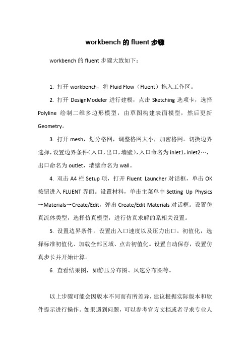
workbench的fluent步骤
workbench的fluent步骤大致如下:
1. 打开workbench,将Fluid Flow(Fluent)拖入工作区。
2. 打开DesignModeler进行建模,点击Sketching选项卡,选择Polyline绘制二维多边形模型,由草图构建表面模型,然后更新Geometry。
3. 打开mesh,划分格网,调整格网大小,加密格网。
切换边界选择,设置边界条件(入口,出口,墙壁),入口命名为inlet1,inlet2…,出口命名为outlet,墙壁命名为wall。
4. 双击A4栏Setup项,打开Fluent Launcher对话框,单击OK 按钮进入FLUENT界面。
设置材料,单击主菜单中Setting Up Physics →Materials→Create/Edit,弹出Create/Edit Materials对话框。
设置仿真流体类型,选择仿真模型,进行仿真求解的系相关设置。
5. 设置边界条件,设置出入口速度以及压力出口。
初值化,选择标准初值化、加载全部区域、点击初值化。
设置自动保存,设置仿真步长并开始计算。
6. 查看结果图,如静压分布图、风速分布图等。
以上步骤可能会因版本不同而有所差异,建议根据实际版本和软件提示进行操作。
如果遇到问题,可以参考官方文档或者寻求专业人
士的帮助。
abaqus中permeability的参数
abaqus中permeability的参数在有限元分析(FEA)中,ABAQUS是广泛使用的一种软件。
它是一种基于有限元方法的仿真软件,在结构、流体、热力学和多物理场等方面具有广泛应用。
其中,Permeability是流体力学中的一个重要参数,它描述了液体、气体或其它流体流经多孔介质时的渗透程度。
在ABAQUS中,Permeability可以用多种方式定义和控制,本文就稍微介绍一下其中一些方法。
一、Fluid Flow模块定义PermeabilityABAQUS中的Fluid Flow模块提供了一种直接定义Permeability 的方法,即通过Darcy's law来描述渗流动态方程。
Darcy's law是描述流体通过多孔介质过程中流动速度和渗透性之间的关系的方程式。
在ABAQUS的Fluid Flow模块中,可以通过定义Darcy's law中的参数K(渗透系数)来明确描述流体对物质的侵蚀程度。
通常K值越大,意味着流体可以更容易地通过多孔介质,因此,经常用K值来衡量多孔介质的渗透性能。
二、Python ScriptingPython Scripting是一种ABAQUS中常用的自动化工具,可以帮助用户更高效地管理和操作模型。
通过Python Scripting,可以自定义程序,用于描述Pervious Concrete(透水混凝土)的渗透性能,并通过预处理程序、后处理程序和有限元分析程序来实现该功能。
用户可以在Python Scripting中使用parametric思路,即将多个参数化方程式组合在一起,以描述不同参数对Permeability的影响。
Python Scripting的优点在于,它可以让用户自由地更改各参数值,以满足不同的建模需求。
三、Particle-Reinforced Composite材料定义方法对于含有Particle-Reinforced的复合材料,可以通过在ABAQUS 的材料图书馆中创建这种类型的材料模型来指定Permeability。
顺序阀的名词解释(一)
顺序阀的名词解释(一)顺序阀的名词解释顺序阀是一种用来控制流体流动方向的装置,可以在不同的工况下实现流体的顺序启闭。
以下是与顺序阀相关的名词解释:1.顺序阀(Sequential Valve)–顺序阀是一种可以根据预设的顺序来控制流体流动的阀门。
它通常由一个或多个阀芯组成,可以根据进入阀门的流体压力或流量来启闭和切换阀芯。
2.阀芯(Valve Spool)–阀芯是顺序阀中的关键组成部分,是一个可以在阀体内移动的圆柱形装置。
通过调整阀芯的位置和角度,可以控制流体的流动,实现不同的工作功能。
3.阀体(Valve Body)–阀体是顺序阀的外壳,用于固定阀芯和连接管道。
它通常由金属材料制成,具有较高的耐压和耐腐蚀性能。
4.进口(Inlet)–进口是指流体进入顺序阀的地方。
顺序阀通常有多个进口,可以实现不同进口的优先级控制。
5.出口(Outlet)–出口是指流体离开顺序阀的地方。
顺序阀通常有多个出口,可以根据不同的工况将流体导向不同的管道。
6.流体压力(Fluid Pressure)–流体压力是指流体对单位面积的压力大小,通常用帕斯卡(Pa)或磅力/平方英寸(psi)来表示。
顺序阀根据流体压力的变化来控制阀芯的启闭和切换。
7.流体流量(Fluid Flow)–流体流量是指单位时间内通过管道或阀门的流体体积。
顺序阀根据流体流量的大小来判断阀芯是否需要启闭和切换。
8.工况(Operating Condition)–工况是顺序阀在特定使用环境下的工作状态。
包括流体压力、流体温度、流体流量等因素的变化。
总结:顺序阀的名词解释包括顺序阀、阀芯、阀体、进口、出口、流体压力、流体流量和工况。
顺序阀通过控制阀芯的位置和角度,根据流体压力和流量的变化,实现流体的顺序启闭和切换。
阀体各部分名称详解
阀体各部分名称详解The valve body is a crucial component of a valve, and its various parts play important roles in regulating fluid flow. 阀体是阀门的关键组成部分,它的各个部分在调节流体流动过程中起着重要作用。
First, let's take a look at the main components of the valve body. The valve body typically consists of the valve chamber, valve seat, and inlet and outlet ports. 首先,让我们来看一下阀体的主要组成部分。
阀体通常由阀腔、阀座和进出口端口组成。
The valve chamber is where the fluid flows through the valve. It is designed to facilitate smooth flow and minimize turbulence, allowing for efficient regulation of the fluid. 阀腔是流体流经阀门的地方。
它的设计旨在促进流体的顺畅流动,并最小化湍流,从而实现高效调节流体的目的。
Next, the valve seat is a critical component that provides a sealing surface for the valve. It ensures that the valve can close tightly to prevent any leakage of fluid. 接下来,阀座是一个提供阀门密封表面的关键部件。
它确保阀门能够紧密关闭,防止流体泄漏。
Inlet and outlet ports are the openings in the valve body that allow the fluid to enter and exit the valve. These ports are strategically positioned to facilitate the flow of fluid and ensure efficient regulation. 进出口端口是阀体上允许流体进出的开口。
流体的特性
pB=pB’ pB=1 gH1+ 2 gH2+p0 pB’= 2 g h+p0
故: 2 g h+p0= 1 gH1+ 2 gH2+p0
h 1gH1 2 gH2 2g
Z1
对于微元垂直液柱(如左 图)其受力情况
上表面作用力:
F1= p1 A 下表面作用力:
F2= p2 A 重力:
G = g A (Z1 - Z2)
26
二、流体静力学基本方程式
p1 G
Z1
p2 Z2
F1= p1 A F2= p2 A G= g A( Z1 - Z2 )
F1 + G = F2
p1 A + g A ( Z1 - Z2 ) = p2 A
当压力不太高,温度不太低的情况下,气体一般可 近似的按理想气体处理,理想气体的密度计算:
PM
RT
P—气体的绝对压强,kPa;
T —气体的绝对温度,K;
M —气体的摩尔质量,kg/kmol;
R —气体状态常数,R=8.314kJ/kmol.K
2020/3/6
12
二、比容
比容是指单位质量流体所具有的体积,多用于气 体。用v表示:
N.m J / kg kg
gz=m/s2.m=m2/s2=J/kg
由上式可知,在静止流体中,不同位置上流体具
有的静压能与位能的值不同,但是两项之和恒为常数, 这说明静止流体中能量守恒且可以相互转换。
2020/3/6
30
三、讨论
1、静力学基本方程式的应用条件:重力场中,静
止的连续的同一种流体;
2020/3/6
32
[例2-2](1)判断下面各式是否成立
- 1、下载文档前请自行甄别文档内容的完整性,平台不提供额外的编辑、内容补充、找答案等附加服务。
- 2、"仅部分预览"的文档,不可在线预览部分如存在完整性等问题,可反馈申请退款(可完整预览的文档不适用该条件!)。
- 3、如文档侵犯您的权益,请联系客服反馈,我们会尽快为您处理(人工客服工作时间:9:00-18:30)。
Methods for visualisingfluidflow∗Graeme TaylorMay15,2004In continuum/fluid mechanics,it is often desirable to be able to visualise the way in which a fluidflows.However,this presents obvious difficulties in that the actualflow is a4-dimensional structure,tracing through spacetime;and so several techniques have been developed to project this into a3-or2-D form.Even with aflow that only varies in two dimensions(as shall be considered here for simplicity),plotting time as a third dimension can cause confusion,so an approach that only requires two dimensions is preferable even at the expense of multiple plots.First however,a precise notion of what it is that should be graphed is needed.At one level this is obvious-we are interested in the velocity offluid particles at various points in spacetime.The issue is which of these two is the more relevant-the particles,or the points.Following the progress of a given particle,and defining the velocity as its rate of change of position,is the Lagrangian or material view,and seems the most obvious.Yet although intuitive,it is often difficult to work with in practice,which gives rise to the Eulerian view of motion:fixing a specific point in3-D space and defining a velocityfield at that point at a given time via the velocity of whichever particle is passing through at the chosen time.Working with this Eulerian view,we have:•A point r=(x,y,z)•A velocityfield u=u(x,y,z,t),the velocity of the particle at r at time t.Note that if the u=0for a given r,then the point is described as a stagnation point;whereas if the partial derivative with respect to time,∂u∗First appeared on Everything2,at /index.pl?nodeStreamlinesFor afixed time T,a streamline is a line for which the tangent is everywhere parallel to the direction offlow,i.e.u(x,y,z,T).Since the velocity will take component form u=(u1,u2,u3)and the tangent will be in the direction d r=(dx,dy,dz),this gives rise to the conditiondxu2=dzdx =u2(x,y,z,T)dx =u3(x,y,z,T)dλ=u,which givesdxdλ=u2dzx=dy0makes you squeamish(you’ll learn not to be too disturbed by a blatant division by zeroif you do a lot of these),then the coupled ODE form in x isdyxdzx=0Which indicates that z is simply a constant,and we have afirst order separable differential equation for x and y,by rearrangement,namelydxyThe solution to this is(as an exercise for the reader)y=AIt is rather difficult to sketch such a thing in plaintext.Depending on the sign of A(unknown) we obtain(for a sketch in the xy plane,with z arbitrary)curves in all four quadrants,which are asymptotic to the x and y axes.You can determine the direction offlow on these curves by checking the original velocityfield.For instance,in thefirst quadrant,x and y are both positive,so thefirst component of u is positive and the second negative,giving aflow downwards to the right. Particle PathsThe concept of the particle path is in line with the Lagrangian view;we consider the particle at a given point at an initial time andfind the curve it traces through thefluid as time increases.For an initial position d at t=0,and position r having moved with velocity u for a time t,we obtain the ODEd rdt=u1(x,y,z,t)dzdt=u3(x,y,z,t)Example particle path calculationRetaining our velocityfield u=(x,−y,0),let usfind the path of the particle which moves through(1,1,0)at time t=0.Evaluating each component equation,we getdxdt=−y so y=Be−t,B∈R a constantdzx .This time we have only a single curve,startingat the point(1,1)(in the xy plane)and hence restricted to thefirst quadrant.The direction of flow should be obvious,but can be confirmed from the velocityfield as before.This curve belongs to the set of those found for the streamlines due to the chosen veolcityfield being steady.3StreaklinesWhilst the particle path tracked the progress of a single particle from a known starting time and position,the streakline represents the status of all particles which passed through afixed point at any time in the past.This can be observed experimentally by injecting dye into thefluid at a certain point-the spread of dye will be the streakline,and will obviously evolve with time,although should theflow be steady then it will be the same as the particle path.To graph the streakline for a known velocityfield can generate considerably more complicated equations than for steamlines or particle paths.In fact,the general solution found for a particle path is the starting point for a streakline calculation.The system to be solved isd rt+1,y,0).Proceed as for a particle pathcalculation tofind the general solution,but don’t plug in the initial conditions-in this case the answer should bex=C(t+1)y=Be tz=AWe seek the path of any particle which passes through(1,1,0)at some time t=τ,so we have C(τ+1)=1=Beτ;A=0.These are reinserted into the general solution to givex=(t+1)x −1by rearrangement,we can eliminate it to obtain the rather involved streaklinein the xy plane:y=exp(t−t+1x))Which can be sketched for various t.4。