BYG20D-TR3中文资料
BP9833D中文规格书

LED 平板灯 LED 日光灯
LED 吸顶灯 其它 LED 照明
引出端排列
GND 1 ROVP 2
NC 3 VCC 4
DIP-8
8 CS 7 CS 6 DRAIN 5 DRAIN
引出端功能
序号
符号
1
GND
2
ROVP
3
NC
4
VCC
功能描述 地
开路保护电压调节端 空 电源
序号 5 6 7 8
符号 DRAIN
CS
功能描述 内置高压功率管漏极
电流采样端
V.1.1
第1 页 共9 页
电路方框图
CSC8933兼容BP9833D
最大额定值
项目 电源脚最大电流 内部高压 MOS 管漏源峰 值电压 电流采样端电压 开路保护电压调节端
功耗
热阻
贮存温度 工作结温 ESD
符号 Icc_max
DRAIN
CS
其中,f 为系统工作频率。CSC8933 的系统工作频率和输入电压成正比关系,设置 CSC8933 系统工作 频率时,选择在输入电压最低时设置系统的最低工作频率,而当输入电压最高时,系统的工作频率 也最高。 CSC8933 设置了系统的最小退磁时间和最大退磁时间,分别为 4.5us 和 240us。由 TOFF 的
过压保护电阻设置
开路保护电压可以通过 ROVP 引脚电阻来设置,ROVP 引脚电压为 0.5V。 当 LED 开路时,输出 电压逐渐上升,退磁时间变短。因此可以根据需要设定的开路保护电压,来计算退磁时间 TOVP。
VCS 是 CS 关断阈值(400mV) VOVP 是需要设定的过压保护点
TOVP
≈
L ×VCS RCS ×VOVP
2008年Ford自动变速箱组件目录说明书

1622008 AUTOMATIC TRANSMISSION KIT & COMPONENTS CATALOG ©2008 PARKER HANNIFIN CORP. ALL RIGHTS RESERVED3790103008397797405R55N / 5R55S / 5R55WRWD 5 SpeedA544510034070670Input ShaftO.Dr. Ring GearO.Dr. CenterShaft783Center SupportInterm. BandDirect DrumForward ClutchForward PlanetReverse BandReverse DrumLow Sprag310037179520036178530311914363912911913910896904896437490996V.B.Parts741E414494765-6370Case313321320Valve Body917747765746322420002OHK Kit004Master L/Steels Kit 006Master 030External Seal Kit1632008 AUTOMATIC TRANSMISSION KIT & COMPONENTS CATALOG ©2008 PARKER HANNIFIN CORP . ALL RIGHTS RESERVEDRWD 5 Speed5R55N / 5R55S / 5R55W862981971961560961971985879565126106146861*229964974877564285872962972104124552894Intermediate Sprag690074266Park Gear264847Park Pawl Assy995-1995-2995-3995916-2916-3919922915916-2916-3919922916263EDA181554770Ext. Hsg.781493305678Output ShaftO.Dr. Band StrutInterm. Band Strut268841Internal Linkage991-2991-3994799991-4761P-4991072410992Yoke1642008 AUTOMATIC TRANSMISSION KIT & COMPONENTS CATALOG©2008 PARKER HANNIFIN CORP. ALL RIGHTS RESERVED*Prefix Letter ‘T’ denotes Toledo-Trans Kit (TTK) Brand Transmission Kits *Prefix Letter ‘B’ denotes Bryco Brand Transmission Kits002.............T16002AP......Overhaul Kit, 5R55N (With Bonded Pistons) 1999-Up ..............................................................1..........002.............T16002GP......Overhaul Kit, 5R55S/5R55W (With Bonded Pistons) 2002-Up..................................................1..........004.............T16004AP......Master L/Steels Kit, 5R55N (With Bonded Pistons) 1999-Up ....................................................1..........004.............T16004GP......Master L/Steels Kit, 5R55S/5R55W (With Bonded Pistons) 2002-Up .......................................1..........006.............T16006AP......Master W/Steels Kit, 5R55N (With Bonded Pistons) 1999-Up...................................................1..........006.............T16006GP......Master W/Steels Kit, 5R55S/5R55W (With Bonded Pistons) 2002-Up ......................................1..........E300...........45019............Gasket, 5R55N Bottom Pan (Plastic With Silicon Bead) OE Style (With Large Holes) 1999-Up 1..........XW4Z-7A191CA D305...........45097668......Gasket, 5R55N/5R55S/5R55W Extension Housing To Case 1999-Up......................................1..........XW4Z-7086-AA A309..........41217............Gasket, 5R55N/5R55S/5R55W Pump Bolt Washer...................................................................AR ........A310..........45097667......Gasket, 5R55N/5R55S/5R55W Pump 1999-Up..........................................................................1..........XW4Z-7A136AB A311...........1988096........O-Ring, 5R55N/5R55S/5R55W Pump Cover 1999-Up ...............................................................1..........XW4Z-7A248AA A313..........1994747........O-Ring, 5R55N Inner Pump Gear 1999-Up.................................................................................1..........F77Z-7L323AA E320...........45097692......Gasket, 5R55N Valve Body Separator Plate To Case 1999-Up ................................................1..........XW4Z-7D100-BF E320...........45097738......Gasket, 5R55S/5R55W Valve Body Separator Plate To Case (Upper) 2002-Up......................1..........1L2Z-7Z490AB-1A070..........70243V..........Seal, 5R55N/5R55S/5R55W Front (No Flange) (Rubber Coated) 1999-Up ..............................1..........F77Z-7A248AA D072...........70083............Seal, 5R55N Linkage 1999-Up ..................................................................................................1..........D5AZ-7B498A D074...........70283............Seal, 5R55N Rear 2WD 2000-Up ...............................................................................................1..........XW4Z-7052AA D074...........70205............Seal, 5R55S/5R55W Rear (W/Long Boot) 2WD 2002-Up .........................................................1..........F6UZ-7052A D074...........70282............Seal, 5R55S/5R55W Extension Housing 4X4 2002-Up .............................................................1..........1L2Z-7052BA175.............6358..............Ring Kit, 5R55N/5R55S/5R55W (2 Metal 4PTFE 2 Torlon Rings) 1999-Up ...............................1..........A178..........45060279......Ring, 5R55N, 5R55W, 5R55S Pump Support (Lock-Up) 1999-Up .............................................1..........B181...........TAW- 2212....Ring, 5R55N, 5R55W, 5R55S Forward Clutch Cylinder 1999-Up .............................................2..........D184...........45060265......Ring, 5R55N, 5R55W, 5R55S Output Shaft 1999-Up.................................................................1..........A179..........30308............Ring, 5R55N, 5R55W, 5R55S Overdrive Brake Drum 1999-Up.................................................2..........B179...........30308P ..........Ring, 5R55N, 5R55W, 5R55S Direct Clutch (Center Support) 1999-Up Torlon .........................2..........119.............45082NR........Friction Module, 5R55N 1999-Up................................................................................................1..........119.............45082LR........Friction Module, 5R55S/5R55W 2002-Up...................................................................................1..........E010...........45040N ..........Filter, 5R55N (3/8” Tall Pick-up Tube) 1999-Up ..........................................................................1..........XW4Z-7A098BB E010...........F-340.............Filter, 5R55S/5R55W (2 1/4” Tall Pick-Up Tube) 2002-Up..........................................................1..........1L2Z-7A098AC5R55N / 5R55S / 5R55WRWD 5 Speed1652008 AUTOMATIC TRANSMISSION KIT & COMPONENTS CATALOG ©2008 PARKER HANNIFIN CORP. ALL RIGHTS RESERVEDB022...........45090............Band, 5R55N Overdrive/Intermediate (Hi-Energy) 1999-Up......................................................2..........XW4Z-7D034BA 030.............45030G..........Bushing Kit, 5R55N/5R55S/5R55W 1999-Up.............................................................................1..........A034..........31530............Bushing, 5R55N/5R55S/5R55W Pump Cover 1999-Up .............................................................1..........A036..........31531............Bushing, 5R55N/5R55S/5R55W Overdrive Sun Gear 1999-Up................................................1..........A036..........45039............Bushing, 5R55N/5R55S/5R55W Stator (Front) 1999-Up ...........................................................1..........A037..........31532............Bushing, 5R55N/5R55S/5R55W Stator (Rear) 1999-Up............................................................1..........A046..........31533............Bushing, 5R55N/5R55S/5R55W Coast Clutch Drum e 56036A................................................................................................................................1..........B211...........45176A..........Washer, 5R55N/5R55S/5R55W Pump To Coast Clutch Drum .063" (Plastic) 1999-Up.............1..........F7TZ-7D014TA B211...........45176B ..........Washer, 5R55N/5R55S/5R55W Pump To Coast Clutch Drum .071" (Plastic) 1999-Up.............1..........F7TZ-7D014MA B211...........45176C ..........Washer, 5R55N/5R55S/5R55W Pump To Coast Clutch Drum .075" (Plastic) 1999-Up.............1..........F7TZ-7D014NA B211...........45176D ..........Washer, 5R55N/5R55S/5R55W Pump To Coast Clutch Drum .079" (Plastic) 1999-Up.............1..........F7TZ-7D014PA B211...........45176E ..........Washer, 5R55N/5R55S/5R55W Pump To Coast Clutch Drum .083" (Plastic) 1999-Up.............1..........F7TZ-7D014RA B211...........45176F ..........Washer, 5R55N/5R55S/5R55W Pump To Coast Clutch Drum .087" (Plastic) 1999-Up.............1..........F7TZ-7D014SA C232...........45145............Washer, 5R55N/5R55S/5R55W Bearing to Forward Hub (Solid Bronze) 1999-Up .................1..........FOTZ-7D090A D263...........45077............Washer, 5R55N/5R55S/5R55W Parking Gear To Case 1999-Up ..............................................1..........D4ZZ-7B368-AD410...........D56955J ........Switch, 5R55N Neutral Safety (12 Prong Connector) 1999-Up ...............................................1..........XW4Z-7F293AA E922...........33991............Nut, 5R55N/S/W Band 1999-Up .................................................................................................2..........380850-SRWD 5 Speed5R55N / 5R55S / 5R55W。
20 20 Gen 3 FurrowForce 快速参考手册说明书

QUICK REFERENCE GUIDE—20|20 GEN 3—FURROWFORCE CONTROL
FurrowForce control button will open the FurrowForce Control Page. If button is not present on Homescreen it will need to be added.
_02 Quick Reference Guide [2022.0.x] 11/16/2021
START HERE
QUICK REFERENCE GUIDE—20|20 GEN 3—FURROWFORCE DIAGNOSE
1 2
Press Diagnose button or Setup > Diagnose on Home Screen, Press the Closing System button on the row unit schematic and then select FurrowForce to open the FurrowForce Diagnose Page.
Reading the Closing Margin Map
A blue dot on the Closing Margin map indicates potential loss of closing. If blue dots are appearing regularly for multiple rows and the Good Closing value in the Closing widget is dropping below 100%, the Closing Target should be increased.
海哥尔德电子产品简介说明书

APRIL 2013Quick-Refere nce GuideLAPTOP, DESKTO P AND VIDEO STORAGE DRIVESSeagate Partner Program MembersVisit the Sales Tools section to access the latestproduct roadmap, end-of-life schedule and product information. DistributorsEMEA SPP Support00-800-6890-8282US Sales Support1-800-SEAGATE or 1-405-324-4700Visit for more information or call 1-800-SEAGATE (1-800-732-4283) © 2013 Seagate Technology LLC. All rights reserved. Printed in USA. Seagate, Seagate Technology and the Wave logo are registered trademarks of Seagate Technology LLC in the United States and/or other countries. Barracuda, G-Force Protection, Momentus, Pipeline HD, SmartAlign and SV35 Series are either trademarks or registered trademarks of Seagate Technology LLC or one of its affiliated companies in the United States and/or other countries. The FIPS logo is a certification mark of NIST, which does not imply product endorsement by NIST, the U.S., or Canadian governments. All other trademarks or registered trademarks are the property of their respective owners. When referring to drive capacity, one gigabyte, or GB, equals one billion bytes and one terabyte, or TB, equals one trillion bytes. Your computer’s operating system may use a different standard of measurement and report a lower capacity. In addition, some of the listed capacity is used for formatting and other functions, and thus will not be available for data storage. Actual data rates may vary depending on operating environment and other factors. The export or re-export of hardware or software containing encryption may be regulated by the US Department of Commerce, Bureau of Industry and Security (for more information go to ). Seagate reserves the right to change, without notice, product offerings or specifications. QR502.15-1304GB, April 2013APRIL 2013Quick-Reference GuideLAPTOP, DESKTOP AND VIDEO STORAGE DRIVESNew Seagate Model Number KeyDesktop, laptop and video storageST 500 DX 001BRANdCAPACiTySegMeNTATTRiBuTeS2 letters ST= Seagate MX= Maxtor2 to 4 digits 80 = 80GB 500 = 500GB 1500 = 1,500GB Capacities>9,999GB: 10 = 10TB 15 = 15TB2 lettersDX = Desktop Premium DM = Mainstream DL = Entry LevelLX = Laptop Premium LM = Laptop Mainstream LT = Laptop Thin VX = Surveillance VM = DVR VT = DVR Thin3 digits, non-intelligent Varies for:Z-height Form Factor RPM Cache Interface SED, FIPS Drop Sensor Interface SpeedView a brief training presentation on how our model numbering format has changed at /seagate/ModelNumber 1 One gigabyte, or GB, equals one billion bytes; and one terabyte, or TB, equals one trillion bytes when referring to drive capacity.2See FIPS 140-2 Level 2 Certificate at /groups/STM/cmvp/documents/140-1/1401vend.htm.37mm z-height expanded to 9.5mm enables compatibility with standard laptop chassis.4Advanced Format 4K sector drive with SmartAlign ™ technology resolves misalignment conditions.5Seagate makes this drive in both 4K and 512-byte sectors. SmartAlign technology is included on 4K sector drives. Both drives are functionally and physically equivalent.6Formerly Barracuda ®drive。
进口编码器欧姆龙光洋品牌内密控等

TRD-2T2500AF
TRD-2T2500BF
TRD-2T2500V
TRD-2T300BF
TRD-2T360BF
TRD-2T360BF-2M
TRD-2T360V
TRD-2T400BF
TRD-2T400V
TRD-2T500B
TRD-2T500BE
TRD-2TH250BF
TRD-2TH360AF
TRD-2TH360BF
TRD-2TH360BF-2M
TRD-2TH500AF
TRD-2TH500V
TRD-2TH600BF
TRD-2TH60B
TRD-2TH60V
TRD-GK10-R
TRD-GK100-BZ
TRD-J400-SW
TRD-J500-RZ
TRD-J500-RZC
TRD-J500-RZL
TRD-J500-RZV
TRD-J500-RZW
TRD-J50-RZ
TRD-J50-RZW
TRD-J600-RZ
TRD-J600-RZC
TRD-J10-SW
TRD-J200-RZ
TRD-NA2048NW
TRD-NA256NW
TRD-NA256NW5M
TRD-NA256PW
TRD-NA256PW5M
TRD-NA360NW
TRD-NA360NW5M
TRD-NA360NWF5M
TRD-NA360PW
TRD-NA360PW5M
TRD-NA720NWF5M
TRD-K1024-YC2
TRD-K1024-YS
HEED 3 技术 用户手册说明书

HEED 3 TECHNICAL / USER MANUAL HELICOPTER EMERGENCY EGRESS DEVICE MODELS 175-001, 175-002, 300-001 & 300-002SUBMERSIBLE SYSTEMS, LLCPhone: (714) 842-6566THE LEADER IN SELF-RESCUE BREATHING SYSTEMSTable of ContentsGeneral Precautions & Warnings (2)How HEED Works (2)Refilling From Fill Station (3)Refilling From Scuba Cylinder (3)Mounting Instructions (4)Pre-Use Check (4)Using HEED (4)General Servicing Information ........................................................................................................................ 4-5 Specifications (6)GENERAL PRECAUTIONS & WARNINGS:∙HEED is shipped empty. Fill prior to use.∙No special training or SCUBA certification necessary for using HEED above ground or at shallow depths.∙Never overfill the HEED system above 3000 psi, the air pressure stamped on the cylinder. ONLY use purified, dry compressed breathing air when filling HEED.∙DO NOT fill or use HEED if it has been exposed to extreme heat exceeding 250ºF, or open flame. Instead, discharge the cylinder completely and return it to an Authorized dealer or the manufacturer for inspection and possible hydrostatic testing.HOW HEED WORKS:Helicopter Emergency Egress Device (HEED) is a high quality emergency breathing system produced and tested by people with more than four decades of manufacturing experience. HEED is made in the U.S.A. by craftsmen dedicated to producing a quality product. Enjoy the peace of mind that having the HEED brings.Regulator Body - Our simple rugged design utilizes the same time proventechnology found in typical regulators used by SCUBA Divers around the world. Ouralways-on, breathe on demand, balanced single stage regulator is easy to use,maintain and service. HEED 3 can be used in any orientation, even upside down.Pressure Indicator - Dial Gauge has an easy to read, color coated display for at-a-glance pressure check in psi and bar.Purge Button - Clears the regulator and empties the cylinder.Mouthpiece– High quality silicone mouthpiece.Check Valve Refill Port– Refillable from an Air Compressor or SCUBA cylinder.3000 PSI Aluminum Cylinder - This cylinder is manufactured just like standardSCUBA cylinders, with the same safety features. The cylinder should be inspectedannually and hydrostatically tested every 5 years.VIP Sticker - Month and year of last cylinder visual inspection.REFILLING HEED FROM A FILL STATION USING #920C ADAPTER:(Use a high-pressure, breathing air quality air compressor designed to fill air systems.)WARNING: If the HEED Check Valve Refill Port or Refill Adapter threads are damaged or worn these parts will require replacement. Continued use may cause injury.CAUTION: DO NOT stand directly over HEED regulator while filling.CAUTION: Ensure the regulator is firmly attached to the cylinder (hand tight, no tools required).1. Unscrew black cap from the Check Valve Refill Port.2. Apply small amount of food grade silicone grease to Refill Port threads with your finger.3. Screw Refill Adapter onto Refill Port until finger tight.NOTE: DO NOT apply a wrench or otherwise overtighten.4. Attach the yoke from the compressor to the Adapter.NOTE: If line is pressurized over 3200 PSI, adjust the line pressure to 3200 PSI.5. Turn the valve on your compressor ON.6. Refill the cylinder to 3200 psi initially, after cooling down the pressure will be approximately 3000 psi.Regulate the flow so that it takes approximately 45-60 seconds to fill the cylinder.NOTE: Filling too fast can generate heat and will result in an incomplete fill after the cylinder cools.NOTE: Fill cylinder slowly and DO NOT OVERFILL to protect the safety burst disc inside the regulator from rupturing. If it ruptures, a new 3300 psi burst disc must be installed before unit can be filled.7. When the cylinder is full, turn the compressor or fill station valve OFF.8. Open bleed knob to release pressure in line. Remove Adapter from compressor yoke.9. Remove Adapter from HEED and replace black cap on Refill Port.10. Check the Pressure Indicator. If the tank is full, the Dial Gauge will read 3000 psi.REFILLING HEED FROM A STANDARD SCUBA CYLINDER USING #910S ADAPTER:WARNING: If the HEED Check Valve Refill Port or Refill Adapter threads are damaged or worn these parts will require replacement. Continued use may cause injury.CAUTION: DO NOT stand directly over HEED regulator while filling.CAUTION: Ensure the regulator is firmly attached to the cylinder (hand tight, no tools required).1. Unscrew black cap from the Check Valve Refill Port.2. Apply small amount of food grade silicone grease to Refill Port threads with your finger.3. Screw Refill Adapter onto Refill Port until finger tight.NOTE: DO NOT apply a wrench or otherwise overtighten.4. Turn knurled ring on Adapter firmly to closed (clockwise) position.5. Attach Refill Adapter to SCUBA cylinder valve.6. Open SCUBA cylinder valve very slowly just until you can hear air passing from one cylinder to the other.NOTE: Filling too fast can generate heat and will result in an incomplete fill after the cylinder cools.NOTE: If air is escaping from the Adapter during filling, close cylinder valve, wait for air to stop and re-tighten knurled ring by turning to closed (clockwise position).7. When at least 2 minutes have elapsed, and air can no longer be heard flowing from the cylinder, turn thecylinder valve completely open to ensure maximum fill.NOTE: SCUBA cylinder must be filled to 3000 psi at beginning of refill procedure in order to fill torecommended full capacity.8. Close SCUBA cylinder valve.9. You must turn the knurled ring on Adapter to open (counter-clockwise) position to relieve pressure in theAdapter.NOTE: You will not be able to remove the Adapter from Refill Port until this is done.10. Remove Adapter from SCUBA cylinder and HEED.11. Replace black cap on Refill Port.MOUNTING INSTRUCTIONS:Optional HEED 3 Holster is designed to attach to a modular style vest (MOLLE).1. Weave the 2 straps on the back of the modular holster through the webbing and snap into place.NOTE: It is important that the operator be able to grip the regulator having sufficient clearance for a pull of at least 6 inches.2. Place unit in Holster and attach flap securely over the regulator ensuring velcro is fully engaged.NOTE: Mouthpiece can face left or right simply by switching mouthpiece cover and lanyard attachment to either side of the holster.3. Attach Mouthpiece Cover.PRE-USE CHECK:1. Check for obvious physical damage, broken or loose parts. Do not use if damaged.2. Visually check Dial Gauge for needle to be within green zone. Refill if necessary.3. Push Purge Button down and release. Purge Button should move up and down freely. To maintain fullpressure do not purge unnecessarily.USING HEED:1. Pull D-ring on flap of Holster to open.2. Grab HEED regulator head and pull out of the Holster. This action will release the Mouthpiece Cover.3. Place HEED regulator into user’s mouth.4. If the system is used underwater press purge button lightly or exhale sharply to expel water from the regulatorprior to inhalation.CAUTION: Failure to purge the HEED regulator before inhaling will result in swallowing water.5. Continue to inhale and exhale to a safe and normal rate of ascent. Take small, slow, steady breaths tomaximize the duration of air supply.NOTE: The HEED utilizes a balanced regulator which means it will provide air in any orientation including the regulator being upside down or sideways.CAUTION: If HEED is used until completely empty underwater, it should be referred for five yearservice.GENERAL SERVICING INFORMATIONNOTE: Ensure HEED is always pressurized whenever it is submerged to prevent water from entering system. If HEED has been emptied of air underwater it should be referred for five year service.NOTE: If a leak or damage is found at any point the unit should be referred for five year service.ANNUAL CHECK: (performed by user):1. Visually check Dial Gauge for needle to be within green zone. If it is not, perform a leak test to determine ifthe HEED is actually leaking or if it just needs to be filled.2. Look for obvious physical damage, such as broken or loose parts. Check openings of diaphragm cover forpresence of foreign objects or punctures of blue diaphragm. Check that all parts are clean and securelyattached.3. Perform a leak test. HEED must be pressurized and needle within the green zone.a. Completely submerge filled unit into a tub of water.b. Shake the unit back and forth several times so that all trapped air is released.c. Hold the unit still and watch for any leaks for 60 seconds (spend 20 seconds at each of the following:mouthpiece opening, side ports, and tank o-ring areas).NOTE: A leak is defined as a continuous bubble at a constant rate.d. If leak is detected, refer unit for five year service.FIVE YEAR SERVICE: (must be done by certified repair technician or returned to manufacturer):1. Every five years the regulator should be overhauled with a complete overhaul kit. Refer to Service Manual forcomplete instructions. Only personnel certified to repair HEED can perform the repair or refer units to themanufacturer for servicing at:Submersible Systems7413 Slater Ave.Huntington Beach, CA 926472. DOT 3AL cylinder: Hydrostatic testing is required every five years. DOT also requires that any cylinderexposed to fire or heat in excess of 350°F be condemned. CE marked cylinder: Refer to local countryregulations for how often hydrostatic testing should occur.NOTE: Any cylinder that shows signs of corrosion, pitting or damage during any service checks should be evaluated further.ROUTINE CARE & STORAGE:1. For general cleaning, use a mild dish soap or Simple Green / biodegradable solution.2. For sanitizing, use a commercially available regulator sanitizer available through a dive shop.3. Keep the threads on both the Refill Port and Refill Adapter clean and lubricated. Use high-quality, non-toxic, food grade silicone grease for best results.NOTE: NEVER use a hydrocarbon based oil (i.e. household oil or motor oil).4. HEED used frequently in a water training environment need extra care:a. After use, rinse and soak for at least 30 minutes in warm, fresh water.b. Gently shake to dislodge any water and wipe dry with a clean towel.c. Will require service every three to six months.5. Store HEED full or with some positive pressure to prevent contaminants from entering the cylinder. Storein a clean, dry environment with optimum temperatures of 50-75ºF for best product performance. Avoid direct sunlight, automobile trunks or other areas subject to temperature extremes.NOTE: Industry guidelines recommend replacing air in cylinders annually.SERIALIZATION:All HEED systems are identified with individual serial numbers. Serial numbers are located on the regulator to the right of the mouthpiece.SPECIFICATIONS:(Continued on next page)。
VDF DUS 系列 万能数控车床 产品介绍说明书
VDF DUS 系列VDF DUS 车削机床用于单件或小批量生产不用再找了。
这里是你能找到的性价比最优的万能数控车床。
VDF Boehringer DUS 系列车床应用广泛。
多种机床型号和大量的选项配置适应广泛的解决方案, 充分满足您的的技术要求,即使是在特殊的应用情况下也具有最优的性价比。
VDF DUS 系列无可置疑的质量2 | VDF Boehringer由于自动循环控制和手动操作的可行性,VDF DUS 系列机床主要用于单件或小批量生产。
自动刀塔和第二个防护门的组合配置,可以进行数控自动加工。
因此在中等批量生产中也具有高效率,可以替代全数控CNC车床。
VDF 560 / 630 DUSVDF 800 / 1000 / 1110 DUS带宽大向后排屑槽的重型刚性盒式床身是高车削效率和保持长期精度的基础3 3 3 33 3 3 3 VDF Boehringer | 3滑台(双 V )和尾座(V 和平面)导轨是成熟的组合。
宽大导轨表面压强低,确保在长期定位精度和重复定位精度情况下高效率导向 。
为避免热量传递影响, 主轴和齿轮箱隔热分开布置。
主轴轴承和高标准的 VDF Boehringer CNC 车床相同。
VDF 400 DUS最小的机床也有最佳表现VDF DUS 系列机床提供高精度和低成本的加工工件的所有先决条件。
4 | VDF Boehringer3 V DF DUS 系列机床在各个方面符合人体工程学设计, 对于操作者加工高精度工件的能力无任何限制。
3机床功能外罩为操作者和环境提供了最佳的安全防护。
转动操作控制面板。
非随行防护门Parat刀塔VDF Boehringer | 5技术参数VDF 400 DUS车削长度 mm 1000回转直径,床身/滑台mm420 / 235横向滑台行程 mm 250刀具截面尺寸, DIN 770 h x wmm25 x 25技术参数Parat刀塔及镗刀杆座Multifix 刀塔VDF 560 / 630 DUS人性化设计获得高生产率3 符合人体工程学的电子手轮布置,堪称艺术设计标准。
Sandvik RD520液压钻机技术规格说明书

KEY FEATURES Hydraulic rock drill Sandvik RD520Drill feed Sandvik TF500-16’BoomSandvik SB90Control system Sandvik THC561Coverage area 14,210 x 8,420 mm (110 m²)Hole lengthUp to 6,180 mmTurning width (T-section)4,730 mm (with TF500-14’)Tramming / drilling width 3,000 mm / 3,000 mm Transport width 2,500 mmTransport height 3,600 mm (*3,190 mm) Transport length 14,930 mm (with TF500-16’)Total weight 27,000 kg (without utility boom)depending on options Total weight29,400 kg (with utility boom)depending on options* Low mounted cabinSandvik DT821-C is a two boom electro hydraulic jumbo for fast and accurate drilling in tunneling and cavern excavation. The hydraulic controlled drilling system with added automatic functions and optional instrumentation enable productive and high quality excavation. Sandvik RD520 rock drills deliver superior performance with high consumable life.Sandvik SB90 universal booms have a large optimum shaped coverage and full automatic parallelism. In addition to face drilling the unit can also be used for crosscutting and bolt hole drilling. An optional utility boom for bolting and utility works is available. The powerful 4-wheel-drive center articulated carrier ensures rapid and safe tramming with good balance. Noise and vibration insulated cabin provides ergonomic and extremely comfortable working place with excellent visibility during tramming and drilling.BOOM TECHNICAL SPECIFICATION 4-3205Boom type Sandvik SB90Parallel coverage 90 m²Parallelism Hydraulic Boom extension 1,800 mm Feed extension 1,650 mm Boom weight, net 2,650 kg Roll-over angle358°HYDRAULIC SYSTEM Powerpack HPP555 (2 x 55 kW)Percussion pump 110 cc (variable)Rotation pump 60 cc (variable)Filtration size 20 micron (pressure)10 micron (return)Oil tank volume 290 liters Tank filling Electric pumpOil coolerWater cooled.Cooling capacity 2 x 30 kWHYDRAULIC ROCK DRILL TECHNICAL SPECIFICATION 2-1950Rock drillSandvik RD520Percussion power 20 kW Percussion pressure Max. 220 bar Percussion rate 74 Hz Stabilizer HydraulicRotation speed Max. 280 rpm (with OMS125)Rotation torque 625 Nm (with OMS125)Hole size (drifting)43 - 64 mm Hole size (cut hole)76 - 127 mm Recommended rod T38 - H35 - R32T38 - R39 - R35Shank adapter T38 (male)Weight 225 kg Length 1,010 mm Profile height90 mmShank lubrication device Air / oil mist, SLU-2Air consumption 250 - 350 l/min Oil consumption180 - 250 g/hFEED TECHNICAL SPECIFICATION 3-1400Feed type Feed force (Max.)Total length (mm)Hole length (mm)Rod length (mm)Net weight (kg)TF51225 kN 5,2703,4403,700500TF51425 kN 5,8804,0504,305530TF51625 kN 6,4904,6604,915560TF51825 kN 7,1005,2705,525590TF52025 kN7,7105,8806,135620CONTROL SYSTEM TECHNICAL SPECIFICATION 5-1020TypeTHC561, hydraulic Manual boom control Direct control Fully proportional Hydraulic parallelism Drilling control Feed / percussion control Automatic cycleStop and return automaticsOptions• Feed length 12’, 14’, 18’, 20’.• Telescopic feed. Sandvik TFX6/12, TFX8/14, TFX10/16.• Rod retainer. SCR with TF feed (incl. safety wire).• Rod retainer. TRR1 with TFX feed (incl. safety wire).Options• Utility boom pump 60cc (gear).• Manual oil filling pump instead of electric.• Vacuum pump for hydraulic system.• Biodegradable oils. Shell Naturelle HFE46 / HFE68.Options• Sandvik HLX5 instead of Sandvik RD520.• Power extractor.Options• Constant speed drilling. Replaces feed / percussion control.• Instrumentation TCAD+ with iSURE I-II design and reporting.• iSure III Analysis (with TCAD+ option).• Extra display for TCAD+ELECTRIC SYSTEM Total input power 135 kW Main switch MSE20IP classification Spec. sheet TS2-132Standard voltage 380 - 690 VAC (± 10%)Starting method Star-delta starter 380 - 690 VAC Automatic cable reel TCR4ECable reel control (in / out)Operator station Front lights(combined working and driving)8 x 50 W LED (24VDC)Rear lights(combined working and driving)4 x 50 W LED (24 VDC)Rear brake / park lights2 x Red LEDUTILITY BOOM (OPTIONAL) TECHNICAL SPECIFICATION 4-3420Boom type SUB3A Boom extension 2 x 2,000 mm Boom weight,net 2,350 kg Max allowed load510 kg Max allowed load with safety canopy400 kgOptions• Safety canopy for utility boom. FOPS approved.• Spot lights for utility boom. 2 x 17 W LED.• Rod racks for utility boom. For 4 pcs of 10 or 12 ft rods.• RX expansion bolt installation kit for utility boom. D30 mm or D41 mmFLUSHING SYSTEM FlushingWaterWater pump type WBP2 HP (11 kW)Water pump capacity 200 l/min Water pump inlet pressure 2 - 7 bar (Min.)Flushing water pressure 10 - 15 barAir compressorCTN10, 1 m³/min (7 bar, 7.5 kW)TRAMMING AND OPERATOR STATION Tramming speed 16 km/h (Horizontal)5.4 km/h (14%=1:7=8°)Gradeability / inclination Max. 15° / 5°Safety cabin FOPS (ISO 3449)OperationStanding drilling, seated tramming Sound pressure level According to EN791Operator station: 79 db(A)Emitted: 125 db(A)Stairs and service lights LED lights FloorWater-washable Air conditioning Filtering capacity EU6/7Cabin heating During tramming and drilling Electricity outlets1 x 12 VACOptions• Optional voltage. 1,000 VAC, 50 Hz.• Electric cable rubber or PUR. Spec sheet TS2-121.• Spooling device for cable reel. for voltages 690 - 1,000 VAC • Electricity outlet in front carrier. 1 x 400 VAC or 1 x Main voltage.• Remote control for reel(s) at rear machine.• Amber strobe light. Flashing (24VDC).Options• Flushing flow supervision.• Air cleaning of hole in addition to water flushing. CTN16 air com -pressor.• Air mist flushing. External air / water supply (incl. IP5 air cleaner).• Additional air capacity for hole cleaning with air. 2 x 80 liters receiver (incl. IP5 air cleaner).• External air connection. IP5 air cleaner.• Water hose reel. THR2.5E. (incl. water hose 38 mm (1 ½”), 65 m).Options• Stainless steel cabin. FOPS (ISO 3449).• Low mounted cabin. Height 3,190 mm.• Reduced tramming speed. 3rd gear lockout.• Reversing camera the rear and side of the machine.• Boot washer at cabin entrance.• CD/MP3 player with radio.Options• High speed carrier. TC8, incl. MB OM906LA, 170 kW, Tier 3, Stage IIIA, with Spicer T32 000 transmission.• High speed carrier. TC8, incl.QSB6.7, 164 kW, Tier 4i, Stage IIIB, with Spicer T32 000 transmission.• Optional engine. QSB4.5, 119 kW, Tier 4i , Stage IIIB.• Foam filled tires.• Exhaust catalyzer. For Tier 3 engines.• Rod rack under carrier. For 12 - 20 ft rods.• Fast filling system. For fuel or complete • Wheel chocks and holders. 2 pieces.• LP cleaning system with reel. Max. 15 bar.• HP cleaning system with reel. Max. 180 bar.• Greasing unit with pump, reel and nozzle. Manual.• Automatic greasing system. Carrier, booms and utility boom.• Handheld fire extinguisher. 1 x 7.7 kg type ABC• Manual fire suppression system. 8 nozzles (incl.1 x extinguisher).• Auto. fire suppression system. 8 nozzles (incl.1 x extinguisher).• Access Detector system (Spec. TS2-211).Packages• Regional packages. EUR package.• Anti-freezing package: Block heater for engine, heater for hy -draulic oil, Water circuit flushing with air, antifreeze adding in water circuit.Extra items• Ground fault and overcurrent protection (VYK).• Spare rock drill.• Spare wheel assembly.• Special tools for rock drill.• Tunnel laser set.• Documentation. Extra manuals.CARRIER Carrier Sandvik TC8Carrier type Frame steering, Orbitrol Frame steering ± 37°Rear oscillation ± 8°Ground clearance 400 mmDiesel engine MB OM904LA, 110 kW Tier 3, Stage IIIATransmissionHydrodynamic, Spicer T20 000Axles Dana Spicer 113 (front)Dana Spicer 123 (rear)Tires14.00-24 PR28Service brakes Hydraulic wet disc brakesParking andemergency brakes SAHR type, fail safe wet disc brakes Fuel tank 150 litersHydraulic jacks TJ60 (front), TJ75 (rear)Hand throttleStandardCentralized greasing points CarrierTF500-12’TF500-14’TF500-16’TF500-18’TF500-20’Feed length 5,330 mm 5,940 mm 6,550 mm 7,160 mm 7,770 mm Overall length14,680 mm 14,900 mm 14,900 mm 15,350 mm 16,400 mm Overall length with TRR114,710 mm14, 930 mm14,930 mm15,380 mm16,430 mmAngle (A)Radius (R)T-cross (C)DT821-C (TF500-12’)mm 37°7,9404,730DT821-C (TF500-14’)mm 37°7,9404,730DT821-C (TF500-16’)mm 37°8,0504,840DT821-C (TF500-18’)mm 37°8,1904,980DT821-C (TF500-20’)mm 37°8,3005,090T S 2-219:01/E N G /M E T R I C © S a n d v i k C o n s t r u c t i o n 2015 S A N D V I K i s a r e g i s t e r e d t r a d e m a r k o w n e d b y S a n d v ik I n t e l l e c t u a l P r o p e r t y A B i n S w e d e n a n d o t h e r c o u n t r i e s .Sandvik Construction reserves the right to make changes to the information on this data sheet without prior notification to users. Please contact a Sandvik representative for clarification on specifications and options.All dimensions in mmAll dimensions in mmAll dimensions in mm。
L3GD20TR;L3GD20;中文规格书,Datasheet资料

August 2011Doc ID 022116 Rev 11/44L3GD20MEMS motion sensor:three-axis digital output gyroscopeFeatures■Three selectable full scales (250/500/2000 dps)■I 2C/SPI digital output interface ■16 bit-rate value data output ■8-bit temperature data output■Two digital output lines (interrupt and data ready)■Integrated low- and high-pass filters with user-selectable bandwidth■Wide supply voltage: 2.4 V to 3.6 V ■Low voltage-compatible IOs (1.8 V)■Embedded power-down and sleep mode ■Embedded temperature sensor ■Embedded FIFO ■High shock survivability■Extended operating temperature range (-40 °C to +85 °C)■ECOPACK ® RoHS and “Green” compliantApplications■Gaming and virtual reality input devices ■Motion control with MMI (man-machine interface)■GPS navigation systems ■Appliances and roboticsDescriptionThe L3GD20 is a low-power three-axis angular rate sensor.It includes a sensing element and an IC interface capable of providing the measured angular rate to the external world through a digital interface (I 2C/SPI).The sensing element is manufactured using a dedicated micro-machining process developed by STMicroelectronics to produce inertial sensors and actuators on silicon wafers.The IC interface is manufactured using a CMOS process that allows a high level of integration to design a dedicated circuit which is trimmed to better match the sensing element characteristics.The L3GD20 has a full scale of ±250/±500/ ±2000 dps and is capable of measuring rates with a user-selectable bandwidth.The L3GD20 is available in a plastic land grid array (LGA) package and can operate within a temperature range of -40 °C to +85 °C.Table 1. Device summaryOrder code Temperature range (°C)Package Packing L3GD20-40 to +85LGA-16 (4x4x1 mm)Tray L3GD20TR-40 to +85LGA-16 (4x4x1 mm)T ape and reelContents L3GD20Contents1Block diagram and pin description . . . . . . . . . . . . . . . . . . . . . . . . . . . . . 71.1Pin description . . . . . . . . . . . . . . . . . . . . . . . . . . . . . . . . . . . . . . . . . . . . . . 72Mechanical and electrical specifications . . . . . . . . . . . . . . . . . . . . . . . . 92.1Mechanical characteristics . . . . . . . . . . . . . . . . . . . . . . . . . . . . . . . . . . . . . 92.2Electrical characteristics . . . . . . . . . . . . . . . . . . . . . . . . . . . . . . . . . . . . . . 102.3Temperature sensor characteristics . . . . . . . . . . . . . . . . . . . . . . . . . . . . . 102.4Communication interface characteristics . . . . . . . . . . . . . . . . . . . . . . . . . 112.4.1SPI - serial peripheral interface . . . . . . . . . . . . . . . . . . . . . . . . . . . . . . . 112.4.2I2C - Inter IC control interface . . . . . . . . . . . . . . . . . . . . . . . . . . . . . . . . 122.5Absolute maximum ratings . . . . . . . . . . . . . . . . . . . . . . . . . . . . . . . . . . . . 132.6Terminology . . . . . . . . . . . . . . . . . . . . . . . . . . . . . . . . . . . . . . . . . . . . . . . 142.6.1Sensitivity . . . . . . . . . . . . . . . . . . . . . . . . . . . . . . . . . . . . . . . . . . . . . . . . 142.6.2Zero-rate level . . . . . . . . . . . . . . . . . . . . . . . . . . . . . . . . . . . . . . . . . . . . 142.7Soldering information . . . . . . . . . . . . . . . . . . . . . . . . . . . . . . . . . . . . . . . . 14 3Application hints . . . . . . . . . . . . . . . . . . . . . . . . . . . . . . . . . . . . . . . . . . . 154Digital main blocks . . . . . . . . . . . . . . . . . . . . . . . . . . . . . . . . . . . . . . . . . 164.1Block diagram . . . . . . . . . . . . . . . . . . . . . . . . . . . . . . . . . . . . . . . . . . . . . . 164.2FIFO . . . . . . . . . . . . . . . . . . . . . . . . . . . . . . . . . . . . . . . . . . . . . . . . . . . . . 164.2.1Bypass mode . . . . . . . . . . . . . . . . . . . . . . . . . . . . . . . . . . . . . . . . . . . . . 174.2.2FIFO mode . . . . . . . . . . . . . . . . . . . . . . . . . . . . . . . . . . . . . . . . . . . . . . . 174.2.3Stream mode . . . . . . . . . . . . . . . . . . . . . . . . . . . . . . . . . . . . . . . . . . . . . 184.2.4Bypass-to-stream mode . . . . . . . . . . . . . . . . . . . . . . . . . . . . . . . . . . . . . 204.2.5Stream-to-FIFO mode . . . . . . . . . . . . . . . . . . . . . . . . . . . . . . . . . . . . . . 204.2.6Retrieve data from FIFO . . . . . . . . . . . . . . . . . . . . . . . . . . . . . . . . . . . . 215Digital interfaces . . . . . . . . . . . . . . . . . . . . . . . . . . . . . . . . . . . . . . . . . . . 225.1I2C serial interface . . . . . . . . . . . . . . . . . . . . . . . . . . . . . . . . . . . . . . . . . . 225.1.1I2C operation . . . . . . . . . . . . . . . . . . . . . . . . . . . . . . . . . . . . . . . . . . . . . 235.2SPI bus interface . . . . . . . . . . . . . . . . . . . . . . . . . . . . . . . . . . . . . . . . . . . 245.2.1SPI read . . . . . . . . . . . . . . . . . . . . . . . . . . . . . . . . . . . . . . . . . . . . . . . . . 26 2/44Doc ID 022116 Rev 1L3GD20Contents5.2.2SPI write . . . . . . . . . . . . . . . . . . . . . . . . . . . . . . . . . . . . . . . . . . . . . . . . 275.2.3SPI read in 3-wire mode . . . . . . . . . . . . . . . . . . . . . . . . . . . . . . . . . . . . 276Output register mapping . . . . . . . . . . . . . . . . . . . . . . . . . . . . . . . . . . . . 297Register description . . . . . . . . . . . . . . . . . . . . . . . . . . . . . . . . . . . . . . . . 317.1WHO_AM_I (0Fh) . . . . . . . . . . . . . . . . . . . . . . . . . . . . . . . . . . . . . . . . . . . 317.2CTRL_REG1 (20h) . . . . . . . . . . . . . . . . . . . . . . . . . . . . . . . . . . . . . . . . . . 317.3CTRL_REG2 (21h) . . . . . . . . . . . . . . . . . . . . . . . . . . . . . . . . . . . . . . . . . . 327.4CTRL_REG3 (22h) . . . . . . . . . . . . . . . . . . . . . . . . . . . . . . . . . . . . . . . . . . 337.5CTRL_REG4 (23h) . . . . . . . . . . . . . . . . . . . . . . . . . . . . . . . . . . . . . . . . . . 347.6CTRL_REG5 (24h) . . . . . . . . . . . . . . . . . . . . . . . . . . . . . . . . . . . . . . . . . . 347.7REFERENCE/DAT ACAPTURE (25h) . . . . . . . . . . . . . . . . . . . . . . . . . . . . 357.8OUT_TEMP (26h) . . . . . . . . . . . . . . . . . . . . . . . . . . . . . . . . . . . . . . . . . . 357.9STATUS_REG (27h) . . . . . . . . . . . . . . . . . . . . . . . . . . . . . . . . . . . . . . . . . 367.10OUT_X_L (28h), OUT_X_H (29h) . . . . . . . . . . . . . . . . . . . . . . . . . . . . . . 367.11OUT_Y_L (2Ah), OUT_Y_H (2Bh) . . . . . . . . . . . . . . . . . . . . . . . . . . . . . . 367.12OUT_Z_L (2Ch), OUT_Z_H (2Dh) . . . . . . . . . . . . . . . . . . . . . . . . . . . . . . 367.13FIFO_CTRL_REG (2Eh) . . . . . . . . . . . . . . . . . . . . . . . . . . . . . . . . . . . . . 367.14FIFO_SRC_REG (2Fh) . . . . . . . . . . . . . . . . . . . . . . . . . . . . . . . . . . . . . . 377.15INT1_CFG (30h) . . . . . . . . . . . . . . . . . . . . . . . . . . . . . . . . . . . . . . . . . . . . 377.16INT1_SRC (31h) . . . . . . . . . . . . . . . . . . . . . . . . . . . . . . . . . . . . . . . . . . . . 387.17INT1_THS_XH (32h) . . . . . . . . . . . . . . . . . . . . . . . . . . . . . . . . . . . . . . . . 397.18INT1_THS_XL (33h) . . . . . . . . . . . . . . . . . . . . . . . . . . . . . . . . . . . . . . . . . 397.19INT1_THS_YH (34h) . . . . . . . . . . . . . . . . . . . . . . . . . . . . . . . . . . . . . . . . 397.20INT1_THS_YL (35h) . . . . . . . . . . . . . . . . . . . . . . . . . . . . . . . . . . . . . . . . . 397.21INT1_THS_ZH (36h) . . . . . . . . . . . . . . . . . . . . . . . . . . . . . . . . . . . . . . . . 407.22INT1_THS_ZL (37h) . . . . . . . . . . . . . . . . . . . . . . . . . . . . . . . . . . . . . . . . . 407.23INT1_DURA TION (38h) . . . . . . . . . . . . . . . . . . . . . . . . . . . . . . . . . . . . . . 40 8Package information . . . . . . . . . . . . . . . . . . . . . . . . . . . . . . . . . . . . . . . . 42 9Revision history . . . . . . . . . . . . . . . . . . . . . . . . . . . . . . . . . . . . . . . . . . . 43Doc ID 022116 Rev 13/44List of tables L3GD20 List of tablesTable 2.Pin description . . . . . . . . . . . . . . . . . . . . . . . . . . . . . . . . . . . . . . . . . . . . . . . . . . . . . . . . . . . 8 Table 3.Mechanical characteristics . . . . . . . . . . . . . . . . . . . . . . . . . . . . . . . . . . . . . . . . . . . . . . . . . . 9 Table 4.Electrical characteristics . . . . . . . . . . . . . . . . . . . . . . . . . . . . . . . . . . . . . . . . . . . . . . . . . . 10 Table 5.Electrical characteristics . . . . . . . . . . . . . . . . . . . . . . . . . . . . . . . . . . . . . . . . . . . . . . . . . . 10 Table 6.SPI slave timing values. . . . . . . . . . . . . . . . . . . . . . . . . . . . . . . . . . . . . . . . . . . . . . . . . . . . 11 Table 7.I2C slave timing values (TBC) . . . . . . . . . . . . . . . . . . . . . . . . . . . . . . . . . . . . . . . . . . . . . . 12 Table 8.Absolute maximum ratings. . . . . . . . . . . . . . . . . . . . . . . . . . . . . . . . . . . . . . . . . . . . . . . . . 13 Table 9.Serial interface pin description . . . . . . . . . . . . . . . . . . . . . . . . . . . . . . . . . . . . . . . . . . . . . . 22 Table 10.I2C terminology. . . . . . . . . . . . . . . . . . . . . . . . . . . . . . . . . . . . . . . . . . . . . . . . . . . . . . . . . . 22 Table 11.SAD+read/write patterns. . . . . . . . . . . . . . . . . . . . . . . . . . . . . . . . . . . . . . . . . . . . . . . . . . . 23 Table 12.Transfer when master is writing one byte to slave . . . . . . . . . . . . . . . . . . . . . . . . . . . . . . . 23 Table 13.Transfer when master is writing multiple bytes to slave . . . . . . . . . . . . . . . . . . . . . . . . . . . 24 Table 14.Transfer when master is receiving (reading) one byte of data from slave . . . . . . . . . . . . . 24 Table 15.Transfer when master is receiving (reading) multiple bytes of data from slave . . . . . . . . . 24 Table 16.Register address map. . . . . . . . . . . . . . . . . . . . . . . . . . . . . . . . . . . . . . . . . . . . . . . . . . . . . 29 Table 17.WHO_AM_I register . . . . . . . . . . . . . . . . . . . . . . . . . . . . . . . . . . . . . . . . . . . . . . . . . . . . . . 31 Table 18.CTRL_REG1 register . . . . . . . . . . . . . . . . . . . . . . . . . . . . . . . . . . . . . . . . . . . . . . . . . . . . . 31 Table 19.CTRL_REG1 description . . . . . . . . . . . . . . . . . . . . . . . . . . . . . . . . . . . . . . . . . . . . . . . . . . 31 Table 20.DR and BW configuration setting . . . . . . . . . . . . . . . . . . . . . . . . . . . . . . . . . . . . . . . . . . . . 31 Table 21.Power mode selection configuration. . . . . . . . . . . . . . . . . . . . . . . . . . . . . . . . . . . . . . . . . . 32 Table 22.CTRL_REG2 register . . . . . . . . . . . . . . . . . . . . . . . . . . . . . . . . . . . . . . . . . . . . . . . . . . . . . 32 Table 23.CTRL_REG2 description . . . . . . . . . . . . . . . . . . . . . . . . . . . . . . . . . . . . . . . . . . . . . . . . . . 32 Table 24.High-pass filter mode configuration . . . . . . . . . . . . . . . . . . . . . . . . . . . . . . . . . . . . . . . . . . 33 Table 25.High-pass filter cut off frequency configuration [Hz]. . . . . . . . . . . . . . . . . . . . . . . . . . . . . . 33 Table 26.CTRL_REG1 register . . . . . . . . . . . . . . . . . . . . . . . . . . . . . . . . . . . . . . . . . . . . . . . . . . . . . 33 Table 27.CTRL_REG3 description . . . . . . . . . . . . . . . . . . . . . . . . . . . . . . . . . . . . . . . . . . . . . . . . . . 33 Table 28.CTRL_REG4 register . . . . . . . . . . . . . . . . . . . . . . . . . . . . . . . . . . . . . . . . . . . . . . . . . . . . . 34 Table 29.CTRL_REG4 description . . . . . . . . . . . . . . . . . . . . . . . . . . . . . . . . . . . . . . . . . . . . . . . . . . 34 Table 30.CTRL_REG5 register . . . . . . . . . . . . . . . . . . . . . . . . . . . . . . . . . . . . . . . . . . . . . . . . . . . . . 34 Table 31.CTRL_REG5 description . . . . . . . . . . . . . . . . . . . . . . . . . . . . . . . . . . . . . . . . . . . . . . . . . . 34 Table 32.REFERENCE register. . . . . . . . . . . . . . . . . . . . . . . . . . . . . . . . . . . . . . . . . . . . . . . . . . . . . 35 Table 33.REFERENCE register description . . . . . . . . . . . . . . . . . . . . . . . . . . . . . . . . . . . . . . . . . . . 35 Table 34.OUT_TEMP register. . . . . . . . . . . . . . . . . . . . . . . . . . . . . . . . . . . . . . . . . . . . . . . . . . . . . . 35 Table 35.OUT_TEMP register description. . . . . . . . . . . . . . . . . . . . . . . . . . . . . . . . . . . . . . . . . . . . . 35 Table 36.STATUS_REG register. . . . . . . . . . . . . . . . . . . . . . . . . . . . . . . . . . . . . . . . . . . . . . . . . . . . 36 Table 37.STATUS_REG description. . . . . . . . . . . . . . . . . . . . . . . . . . . . . . . . . . . . . . . . . . . . . . . . . 36 Table 38.REFERENCE register. . . . . . . . . . . . . . . . . . . . . . . . . . . . . . . . . . . . . . . . . . . . . . . . . . . . . 36 Table 39.REFERENCE register description . . . . . . . . . . . . . . . . . . . . . . . . . . . . . . . . . . . . . . . . . . . 37 Table 40.FIFO mode configuration . . . . . . . . . . . . . . . . . . . . . . . . . . . . . . . . . . . . . . . . . . . . . . . . . . 37 Table 41.FIFO_SRC register. . . . . . . . . . . . . . . . . . . . . . . . . . . . . . . . . . . . . . . . . . . . . . . . . . . . . . . 37 Table 42.FIFO_SRC register description. . . . . . . . . . . . . . . . . . . . . . . . . . . . . . . . . . . . . . . . . . . . . . 37 Table 43.INT1_CFG register. . . . . . . . . . . . . . . . . . . . . . . . . . . . . . . . . . . . . . . . . . . . . . . . . . . . . . . 37 Table 44.INT1_CFG description . . . . . . . . . . . . . . . . . . . . . . . . . . . . . . . . . . . . . . . . . . . . . . . . . . . . 38 Table 45.INT1_SRC register. . . . . . . . . . . . . . . . . . . . . . . . . . . . . . . . . . . . . . . . . . . . . . . . . . . . . . . 38 Table 46.INT1_SRC description . . . . . . . . . . . . . . . . . . . . . . . . . . . . . . . . . . . . . . . . . . . . . . . . . . . . 38 Table 47.INT1_THS_XH register. . . . . . . . . . . . . . . . . . . . . . . . . . . . . . . . . . . . . . . . . . . . . . . . . . . . 39 Table 48.INT1_THS_XH description. . . . . . . . . . . . . . . . . . . . . . . . . . . . . . . . . . . . . . . . . . . . . . . . . 39 Table 49.INT1_THS_XL register. . . . . . . . . . . . . . . . . . . . . . . . . . . . . . . . . . . . . . . . . . . . . . . . . . . . 39 4/44Doc ID 022116 Rev 1L3GD20List of tables Table 50.INT1_THS_XL description . . . . . . . . . . . . . . . . . . . . . . . . . . . . . . . . . . . . . . . . . . . . . . . . . 39 Table 51.INT1_THS_YH register. . . . . . . . . . . . . . . . . . . . . . . . . . . . . . . . . . . . . . . . . . . . . . . . . . . . 39 Table 52.INT1_THS_YH description. . . . . . . . . . . . . . . . . . . . . . . . . . . . . . . . . . . . . . . . . . . . . . . . . 39 Table 53.INT1_THS_YL register. . . . . . . . . . . . . . . . . . . . . . . . . . . . . . . . . . . . . . . . . . . . . . . . . . . . 39 Table 54.INT1_THS_YL description . . . . . . . . . . . . . . . . . . . . . . . . . . . . . . . . . . . . . . . . . . . . . . . . . 39 Table 55.INT1_THS_ZH register. . . . . . . . . . . . . . . . . . . . . . . . . . . . . . . . . . . . . . . . . . . . . . . . . . . . 40 Table 56.INT1_THS_ZH description . . . . . . . . . . . . . . . . . . . . . . . . . . . . . . . . . . . . . . . . . . . . . . . . . 40 Table 57.INT1_THS_ZL register . . . . . . . . . . . . . . . . . . . . . . . . . . . . . . . . . . . . . . . . . . . . . . . . . . . . 40 Table 58.INT1_THS_ZL description . . . . . . . . . . . . . . . . . . . . . . . . . . . . . . . . . . . . . . . . . . . . . . . . . 40 Table 59.INT1_DURATION register . . . . . . . . . . . . . . . . . . . . . . . . . . . . . . . . . . . . . . . . . . . . . . . . . 40 Table 60.INT1_DURATION description. . . . . . . . . . . . . . . . . . . . . . . . . . . . . . . . . . . . . . . . . . . . . . . 40 Table 61.Document revision history . . . . . . . . . . . . . . . . . . . . . . . . . . . . . . . . . . . . . . . . . . . . . . . . . 43Doc ID 022116 Rev 15/44List of figures L3GD20 List of figuresFigure 1.Block diagram . . . . . . . . . . . . . . . . . . . . . . . . . . . . . . . . . . . . . . . . . . . . . . . . . . . . . . . . . . . 7 Figure 2.Pin connection . . . . . . . . . . . . . . . . . . . . . . . . . . . . . . . . . . . . . . . . . . . . . . . . . . . . . . . . . . . 7 Figure 3.SPI slave timing diagram . . . . . . . . . . . . . . . . . . . . . . . . . . . . . . . . . . . . . . . . . . . . . . . . . . 11 Figure 4.I2C slave timing diagram . . . . . . . . . . . . . . . . . . . . . . . . . . . . . . . . . . . . . . . . . . . . . . . . . . 12 Figure 5.L3GD20 electrical connections and external component values . . . . . . . . . . . . . . . . . . . . 15 Figure 6.Block diagram. . . . . . . . . . . . . . . . . . . . . . . . . . . . . . . . . . . . . . . . . . . . . . . . . . . . . . . . . . . 16 Figure 7.Bypass mode . . . . . . . . . . . . . . . . . . . . . . . . . . . . . . . . . . . . . . . . . . . . . . . . . . . . . . . . . . . 17 Figure 8.FIFO mode . . . . . . . . . . . . . . . . . . . . . . . . . . . . . . . . . . . . . . . . . . . . . . . . . . . . . . . . . . . . . 18 Figure 9.Stream mode . . . . . . . . . . . . . . . . . . . . . . . . . . . . . . . . . . . . . . . . . . . . . . . . . . . . . . . . . . . 19 Figure 10.Bypass-to-stream mode . . . . . . . . . . . . . . . . . . . . . . . . . . . . . . . . . . . . . . . . . . . . . . . . . . . 20 Figure 11.Trigger stream mode . . . . . . . . . . . . . . . . . . . . . . . . . . . . . . . . . . . . . . . . . . . . . . . . . . . . . 20 Figure 12.Read and write protocol . . . . . . . . . . . . . . . . . . . . . . . . . . . . . . . . . . . . . . . . . . . . . . . . . . . 25 Figure 13.SPI read protocol . . . . . . . . . . . . . . . . . . . . . . . . . . . . . . . . . . . . . . . . . . . . . . . . . . . . . . . . 26 Figure 14.Multiple byte SPI read protocol (2-byte example). . . . . . . . . . . . . . . . . . . . . . . . . . . . . . . . 26 Figure 15.SPI write protocol . . . . . . . . . . . . . . . . . . . . . . . . . . . . . . . . . . . . . . . . . . . . . . . . . . . . . . . . 27 Figure 16.Multiple byte SPI write protocol (2-byte example). . . . . . . . . . . . . . . . . . . . . . . . . . . . . . . . 27 Figure 17.SPI read protocol in 3-wire mode. . . . . . . . . . . . . . . . . . . . . . . . . . . . . . . . . . . . . . . . . . . . 28 Figure 18.INT1_Sel and Out_Sel configuration block diagram. . . . . . . . . . . . . . . . . . . . . . . . . . . . . . 35 Figure 19.Wait disabled . . . . . . . . . . . . . . . . . . . . . . . . . . . . . . . . . . . . . . . . . . . . . . . . . . . . . . . . . . . 41 Figure 20.Wait enabled. . . . . . . . . . . . . . . . . . . . . . . . . . . . . . . . . . . . . . . . . . . . . . . . . . . . . . . . . . . . 41 Figure 21.LGA-16: mechanical data and package dimensions . . . . . . . . . . . . . . . . . . . . . . . . . . . . . 42 6/44Doc ID 022116 Rev 1Doc ID 022116 Rev 17/441 Block diagram and pin descriptionFigure 1.Block diagramNote:The vibration of the structure is maintained by drive circuitry in a feedback loop. The sensing signal is filtered and appears as a digital signal at the output.1.1 Pin descriptionFigure 2.Pin connectionFIFOTRIMMING CIRCUITSREFERENCEMIXERCHARGE AMPCLOCK LOW-PASS FILTER+Ωx,y,zI2C SPICSSCL/SPCSDA/SDO/SDI SDOY+Z+Y-Z-X+X-DRIVING MASSFeedback loopM U XA D D C I G I T A LF I L T E R I N GCONTROL LOGIC&INTERRUPT GEN.INT1DRDY/INT2A D C T E M P E R A T U R ES E N S O R12&PHASE GENERATORAM10126V1(TOP VIEW)DIRECTION S OF THE DETECTABLE ANGULAR RATE SXVdd_IO S CL/S PC S DA/S DI/S DOS DO/S A0RE S RE S RE S RE SI N T 1D R D Y /I N T 2C SR E SR E SR E SV d dG N D18125491316+ΩZ+ΩXBOTTOMVIEW+ΩYAM10127V18/44Doc ID 022116 Rev 1Table 2.Pin descriptionPin#Name Function1Vdd_IO (1)1.100 nF filter capacitor recommended.Power supply for I/O pins 2SCL SPC I 2C serial clock (SCL)SPI serial port clock (SPC)3SDA SDI SDO I 2C serial data (SDA)SPI serial data input (SDI)3-wire interface serial data output (SDO)4SDO SA0SPI serial data output (SDO)I 2C less significant bit of the device address (SA0)5CS I 2C/SPI mode selection (1: SPI idle mode / I 2C communication enabled; 0: SPI communication mode / I 2C disabled)6DRDY/INT2Data ready/FIFO interrupt (Watermark/Overrun/Empty)7INT1Programmable interrupt 8Reserved Connect to GND 9Reserved Connect to GND 10Reserved Connect to GND 11Reserved Connect to GND 12Reserved Connect to GND 13GND 0 V supply14Reserved Connect to GND with ceramic capacitor (2)2. 1 nF min value must be guaranteed under 11 V bias condition.15Reserved Connect to Vdd 16Vdd (3)3.100 nF plus 10 µF capacitors recommended.Power supply2 Mechanical and electrical specifications2.1 Mechanicalcharacteristics@ Vdd = 3.0 V, T = 25 °C unless otherwise noted.Table 3.Mechanical characteristics(1)Symbol Parameter Test condition Min. Typ.(2)Max.UnitFS Measurement range User-selectable±250dps ±500±2000So Sensitivity FS = 250 dps8.75mdps/digit FS = 500 dps17.50FS = 2000 dps70SoDr Sensitivity change vs.temperatureFrom -40 °C to +85 °C±2%DVoff Digital zero-rate level FS = 250 dps±10dps FS = 500 dps±15FS = 2000 dps±75OffDr Zero-rate level changevs. temperatureFS = 250 dps±0.03dps/°CFS = 2000 dps±0.04dps/°CNL Non linearity Best fit straight line0.2% FS Rn Rate noise density0.03ODR Digital output data rate 95/190/380/760HzTop Operating temperaturerange-40+85°C1.The product is factory calibrated at 3.0 V. The operational power supply range is specified in Table4.2.Typical specifications are not guaranteed.dps Hz(⁄Doc ID 022116 Rev 19/4410/44Doc ID 022116 Rev 12.2 Electrical characteristics@ Vdd =3.0 V , T=25 °C unless otherwise noted.2.3 Temperature sensor characteristics@ Vdd =3.0 V , T=25 °C unless otherwise noted.Table 4.Electrical characteristics (1)Symbol ParameterTest conditionMin.Typ.(2)Max.Unit Vdd Supply voltage2.43.03.6V Vdd_IO I/O pins supply voltage (3) 1.71Vdd+0.1V Idd Supply current 6.1mA IddSL Supply currentin sleep mode (4)Selectable by digital interface2mA IddPdn Supply current in power-down mode Selectable by digital interface5µA VIH Digital high level input voltage0.8*Vdd_IOV VIL Digital low level input voltage0.2*Vdd_IO V T opOperating temperature range-40+85°C1.The product is factory calibrated at 3.0 V.2.Typical specifications are not guaranteed.3.It is possible to remove Vdd maintaining Vdd_IO without blocking the communication busses; in this condition themeasurement chain is powered off.4.Sleep mode introduces a faster turn-on time relative to power-down mode.Table 5.Electrical characteristics (1)Symbol ParameterTest conditionMin.Typ.(2)Max.Unit TSDr T emperature sensor output change vs. temperature--1°C/digit TODR T emperature refresh rate 1Hz T opOperating temperature range-40+85°C1.The product is factory calibrated at 3.0 V.2.Typical specifications are not guaranteed.分销商库存信息:STML3GD20TR L3GD20。
变压器单元D3及D类型商品简介说明书

D3RETROFIT TERMINAL UNITSDRound Duct External Retrofit Terminal UnitConver t existing constant volume systems or old "system power ed" mechanical r egulator ter minals to ener gy efficient variable volume operation.• Available in 10 sizes to suit and install simply in ound ductwork. 0 – 4050 cfm (0 – 1911 l/s).• Va ious configu ations custom fab icated to suit individual applications.• Pressure dependent or independent airflow control.• Diamond Flow multi-point aver aging flow sensor on pr essur e independent models.• Digital, electric, analog electronic or pneumatic control.Model 36VRR See page D5Rectangular Slide-in Retrofit Terminal UnitConvert existing constant volume systems to energy efficientvariable volume operation.• Available in 15 valve sizes to handle a large range of air volumes. 0 – 15000 cfm (0 – 7079 l/s).• Custom fab icated to suit any duct size f om 5" x 5" (127 x 127) up to 52" x 26" (1321 x 660).• Diamond Flow multi-point averaging sensor.• Pressure independent airflow control.• Digital, analog electronic or pneumatic control.Model 36VRSSee Page D10GENERAL PRODUCT OVERVIEWInternal Retrofit Terminal UnitsDesigned to replace the mechanical regulators in old systempower ed ter minal units in or der to substantially lower the ope r ational static p r essu r e r equi r ement. The ai r valves include a damper , flow sensor and actuator and make use of state-of-the-art controls in order to reduce operating cost.• Custom built on a specific project basis.• Variable or constant volume pressure independent airflow control.• Diamond Flow multi-point averaging flow sensor.• Models available to r etr ofit most br and name mechanical regulator design terminal units.• Digital, analog electronic or pneumatic control.Model 36VRTR Contact your Nailor Sales Rep.Retrofit Terminal Units• Convert Constant Air Volume Systems to Variable Air Volume.• Convert Constant Volume Dual Duct Systems to Variable Air Volume.• Convert Multizone Systems to Variable Air Volume.• Convert Mechanical Constant Volume Regulators to Low Pressure Digital, Analog Electronic or Pneumatic Controls.Nailor manufactures a range of standard and custom design retrofit terminal units for all applications.Model 36VRRModel 36VRS Model 36VRTRModel 36VRSD4R E T R O F I T T E R M I N A L U N I T SConstant Volume Reheat SystemCold ai f om the cent al station is dist ibuted th ough the existing main t unk and b anch ducts. The Model 36VRS Retrofit Terminals will convert the constant volume system to pressure independent variable air volume operation.Each 36VRS te r minal is signaled by a di r ect acting the r mostat. The p r essu r e independent minimum ai r flow is set at a thermostat output pressure of 8 psi or less, while the maximum is set at 13 psi or greater.The existing reheat coil in each zone is actuated on a fall in room temperature, as the thermostat output decreases from 8 to 3 psi.The fan capacity must be reduced since the total air volume is reduced.Multizone SystemHot or cold air from the central station multizone air handler is distributed through the existing zone system. The Series 36VR Retrofit Terminals will convert the multizone system to variable air volume operation.The zone damper s in the centr al station air handler ar e made with two-position actuator s; each zone is fully open, either heating or cooling. There is no mixing. (Controls may be selected for an outdoor thermostat, a manual selector or changeover signal.)A dual function ther mostat in each zone is dir ect acting for cooling, r ever se acting for heating. In r esponse to the r oom temper atur e, the ther mostat r esets the velocity contr oller for pressure independent control of the Series 36VR .The fan capacity may be reduced since the total air volume is reduced.Some Typical Applications for the Model Series 36VR Retrofit Terminal UnitsDual Duct SystemHot and cold air from the central station is distributed through the existing supply ducts and terminals. The Series 36VR Retrofit Terminals will convert the constant volume system to variable air volume pressure independent operation.Remove the mechanical constant volume regulator from the existing ter minal, while a Model 36VRS is installed in the dischar ge box or duct. A dir ect acting ther mostat contr ols both the 36VRS unit and the modulating tandem damper in the existing box. On a rise in room temperature, the 36VRS reduces the hot airflow. At the minimum setting, the damper in the existing terminal begins to modulate, and mixing occurs. A fur ther temper atur e r ise incr eases the cold air flow to the maximum.The fan capacity may be r educed down since the total air volume is reduced.D5RETROFIT TERMINAL UNITSDModel 36VRR is designed for r ound ductwor k r etr ofit application. Ter minals ar e available in 10 sizes and ar e nominally undersized to ensure a good fit.Easy, low-cost installation into existing ductwor k. The installer cuts out a section in the round duct and replaces the duct section with the conversion unit.STANDARD FEATURES:• Casing 22 ga. (0.86), corrosion-resistant steel with stiffening beads. Sizes 14 and 16 are 20 ga. (1.0).• Blade: Two layers of 22 ga. (0.86), cor osion-r esistant steel laminated together (equivalent to 16 gauge) with across-linked polyurethane peripheral gasket for tight shut-off, 90° rotation, CW to close. Damper leakage is less than 1% of terminal rated airflow 3” w.g. (750 Pa) as tested in accordance with ANSI/ASHRAE Standard 130.• Bearing: Self-lubricating oilite bronze and less than 2% at 6” w.g. (1500 Pa).• Drive Shaft/Axles: 1/2” (13) diameter plated steel, double-bolted to blades. Indicator mark on the end of the shaft to show damper position.• Full electrical controls enclosure for factory mounted DDC and analog electronic controls.• Multi-point aver aging ‘Diamond Flow’ sensor . Aluminum constr uction. Gauge taps ar e pr ovided for field balancing when controls are factory mounted.• Right-hand contr ol location is standar d (as shown). Left-hand is optional.Options:• FMI Removable Flow Sensor• Available in Type 304 and 316 stainless steel construction for laboratory/fume hood exhaust applications.• Controls enclosure for field mounted controls.• 24 volt control transformer. • Toggle disconnect switch.• Pneumatic o Analog Elect onic P essu e Independent controls by Nailor. Factory mounted and calibrated.• Digital contr ols by BMS Contr actor. Factor y mounted byNailor.FACTORY MOUNTED CONTROLSD6R E T R O F I T T E R M I N A L U N I T S4GEQOOGPFGF #KTƀQY 4CPIGU (QT /QFGN 844 4QWPF 4GVTQſV 6GTOKPCN 7PKVUThe r ecommended ai r flow r anges below a r e fo r Round Duct Ret ofit Te minal Units with p essu e independent cont ols and ar e pr esented as r anges for total and contr oller specific minimum and maximum airflow. Airflow ranges are based upon maintaining reasonable sound levels and controller limits using Nailor’s Diamond Flow Sensor as the air flow measur ing device. For a given unit size, the minimum, auxiliar y minimum (wher e applicable) and the maximum flow setting must be within the r ange limits to ensur e pressure independent operation, accuracy and repeatability. Minimum airflow limits are based upon .02" w.g. (5 Pa) differential p r essu r e signal f r om Diamond Flow Senso r on analog/digital contr ols and .03" (7.5) for pneumatic contr ollers. This is a realistic low limit for many transducers used in the digital controls industry. Check with your controls supplier for minimum limits. Setting airflow minimums lower , may cause hunting and failur e to meet minimum ventilation requirements. Factory settings will therefore not be made outside these r anges. A minimum setting of zer o (shut-off) is also available. Where an auxiliary setting is specified, the value must be greater than the minimum setting.The high end of the tabulated Total Airflow Range on pneumatic and analog electr onic contr ols r epr esents the Diamond Flow Sensor ’s differential pressure reading at 1" w.g. (250 Pa). The high end airflow range for digital controls is represented by the indicated transducer differential pressure.ASHRAE 130 "Per for mance Rating of Air Ter minals" is the method of test for the cer tification pr ogr am. The "standar d r ating condition" (certification rating point) airflow volumes for each terminal unit primary valve size ar e tabulated below per AHRI Standar d 880. These air volumes equate to an approximate inlet velocity of 2000 fpm (10.2 m/s).When digital or other controls are mounted by Nailor, but supplied by others, these values are guidelines only, based upon experience with the majority of controls currently available. Controls supplied by others for factory mounting are configured and calibrated in the field. Airflow settings on pneumatic and analog controls supplied by Nailor are factory preset when provided.Model 36VRRImperial Units, Cubic Feet per MinuteMetric Units, Liters per SecondD7RETROFIT TERMINAL UNITSDPerformance Data • NC Level Application GuideModel 36VRRPerformance Notes:1. NC levels ar e calculated fr om thepublished r aw data and based on pr ocedur es outlined in AHRI Standar d 885, Appendix E. 2. Discha r ge sound attenuation deductions are based on environmental effect, duct lining, br anch power division, insulated flex duct, end r eflection and space effect and are as follows:3. Radiated sound attenuation deductions are based on a mineral tile ceiling and envi onmental effect and are as follows:0LQ LQOHW ¨3V LV WKH PLQLPXP VWDWLF p r essu r e r equi r ed to achieve r ated airflow (damper full open).5. Dash (–) in space denotes an NC level of less than 20.Discharge attenuation Octave Band234567< 300 cfm 242839535940300 – 700 cfm 272940515339> 700 cfm293041515239Radiation attenuationOctave Band 234567Total dB reduction181920263136D8R E T R O F I T T E R M I N A L U N I T SPerformance Notes:1. Discharge sound power is the noise emitted from the unit discharge into the downstream duct.2. Sound power levels are in decibels, dB re 10-12 watts.3. All sound data listed by octave bands is raw data without any corrections for room absorption or duct attenuation.4. Min. inlet ţPs is the minimum ope r ating p r essu r e r equi r ement (damper full open).5. Data der ived fr om tests conducted in acco r dance with ANSI/ASHRAEStandard 130 and AHRI Standard 880.RETROFIT TERMINAL UNITS D Performance Notes:1. Radiated sound powe r is the breakout noise transmitted through the unit casing walls.2. Sound power levels are in decibels, dB re 10-12 watts.3. All sound data listed by octave bandsis raw data without any corrections forroom absorption or duct attenuation.4. Min. inlet ţPs is the minimumope r ating p r essu r e r equi r ement(damper full open).5. Data der ived fr om tests conductedin acco r dance with ANSI/ASHRAEStandard 130 and AHRI Standard 880.D9D10R E T R O F I T T E R M I N A L U N I T SSTANDARD FEATURES:• Damper: 16 ga. (1.6) galvanized steel blade and frame construction with extruded PVC blade seals and metallic side jamb seals. Leakage is less than 2% of nominal *******"w.g.(746Pa)astestedinaccordancewith ASHRAE Standard 130.• Bea r ings: Celcon ®.• Dr ive Shaft: 1/2" (13) dia. plated steel, double-bolted to blade. Indicator mar k on the end of the shaft to show damper position. 90o rotation. CW to close.• Full electrical controls enclosure for factory mounted DDC and analog electronic controls.• Multi-point ave r aging ‘Diamond Flow’ senso r : Aluminum. Gauge taps ar e pr ovided for field balancing when controls are factory mounted.• Gasket under the mounting plate and around periphery of terminal insert seal the unit to the sides of the duct.Options:• Controls enclosure for field mounted controls.• 24 volt control transformer. • Toggle disconnect switch.• Pneumatic o r Analog Elect r onic P r essu r e Independent controls by Nailor. Factory mounted and calibrated.• Digital contr ols by BMS Contr actor. Factor y mounted by Nailor.A slide-in type Retrofit Air Terminal Unit forsquar e or r ectangular ductwor k. Conver ts constant volume systems to var iable air volume. Available in 15 individual valve sizes up to 15,000 cfm (7079 l/s). Nominal valve size is the same as smallest available duct size in table. Each unit (valve) size is available to suit var ious duct sizes asshown in the table. Top, bottom and/or side blank-off plates ar e used to br ing valve up to the r equir ed nominal ductwor k dimension. Airflow ranges are based on valve size and acoustical considerations for duct velocity. Model 36VRS is available to suit duct sizes within the tabulated range in 1" (25) increments.Simple, low cost installation into existing ductwork. The installer cuts a rectangular hole in the side of the duct, cuts away the insulation (where present), slides the unit into the duct and screws the mounting plate to the side of the duct.Dimensional Data:D11RETROFIT TERMINAL UNITSDRecommended Airflow RangesFor Model 36VRS Slide-in Retrofit Terminal UnitsThe r ecommended air flow r anges below ar e for ter minal units with pressure independent controls and are based upon controller sensitivity limits as shown for each control type and acoustical consideration for duct velocity. For a given unit size, the minimum, auxiliar y minimum (wher e applicable) and the maximum flow settings must be within the r ange limits to ensur e pr essur e independent oper ation, accur acy and repeatability. For these reasons, factory settings will not be made outside these r anges. A minimum setting of zer o (shut-off) is also available. Wher e an auxiliar y setting is specified, the value must be greater than the minimum setting.When digital or other controls are mounted by Nailor, but supplied by others, these values are guidelines only, based upon experience with the majority of controls currently available. Controls supplied by others for factory mounting are configured and calibrated in the field.Model 36VRSModel 36VRS Square or RectangularD12R E T R O F I T T E R M I N A L U N I T SPerformance Data • NC Level Application GuideModel 36VRSFor full performance table notes, see page D7.D13RETROFIT TERMINAL UNITSDPerformance Data • NC Level Application GuideModel 36VRSFor full performance table notes, see page D7.D14R E T R O F I T T E R M I N A L U N I T SSTANDARD FEATURES:• 22 ga. (0.86) corrosion-resistant steel casing with stiffening beads and corrosion-resistant steel blade up to 12" (305) dia., 20 ga. (1.00) over 12" (305) dia.• Sized to fit nominal round duct sizes.• Inlet and outlet stiffening beads p ovide a means fo secure flexible duct connection.• Balancing damper with hand locking quadrant.• Multi-point aver aging Diamond Flow Sensor : Aluminum construction.• Sensor design minimizes pressure drop and regenerated noise.The Model 36FMSD Flow Measuring Station is a multi-point aver aging air flow sensor combined with integr al balancing damper. The 36FMSD allows the field balancer to measure and adjust the airflow to a diffuser or other air terminal device located downstream.The 36FMSD is an especially useful option for balancing individual displacement ventilation diffusers.A chart is provided on the unit which gives airflow vs. signal differential pressure for direct reading of airflow.Dimensional Data – 36MSFD。
美欧电子 3R3型号电感说明书
Dimensions: [mm]Scale - 10:1Product Marking:Marking3R3 (Inductance Code)744383330337443833303374438333033B CC(mm)D(mm)min.min.12,8020,207443833303374438333033T e m p e r a t u r eT pT L74438333033Cautions and Warnings:The following conditions apply to all goods within the product series of WE-MAPI ofWürth Elektronik eiSos GmbH & Co. KG:General:•This electronic component was designed and manufactured for use in general electronic equipment.•Würth Elektronik must be asked for written approval (following the PPAP procedure) before incorporating the components into any equipment in fields such as military, aerospace, aviation, nuclear control, submarine, transportation (automotive control, train control, ship control), transportation signal, disaster prevention, medical, public information network, etc. where higher safety and reliability are especially required and/or if there is the possibility of direct damage or human injury.•Electronic components that will be used in safety-critical or high-reliability applications, should be pre-evaluated by the customer. •The component is designed and manufactured to be used within the datasheet specified values. If the usage and operation conditions specified in the datasheet are not met, the wire insulation may be damaged or dissolved.•Do not drop or impact the components, the component may be damaged.•Würth Elektronik products are qualified according to international standards, which are listed in each product reliability report. Würth Elektronik does not guarantee any customer qualified product characteristics beyond Würth Elektroniks’ specifications, for its validity and sustainability over time.•The customer is responsible for the functionality of their own products. All technical specifications for standard products also apply to customer specific products.Product specific:Soldering:•The solder profile must comply with the technical product specifications. All other profiles will void the warranty.•All other soldering methods are at the customers’ own risk.•To improve the solderability of bottom termination components please refer to appnote ANP036 on our homepage.•Make sure that you use the correct thickness of solder paste to avoid an insufficient soldering result. We recommend 100µm solder paste as a reference.Cleaning and Washing:•Washing agents used during the production to clean the customer application may damage or change the characteristics of the wire insulation, marking or plating. Washing agents may have a negative effect on the long-term functionality of the product. Potting:•If the product is potted in the costumer application, the potting material may shrink or expand during and after hardening. Shrinking could lead to an incomplete seal, allowing contaminants into the core. Expansion could damage the components. We recommend a manual inspection after potting to avoid these effects.Storage Conditions:• A storage of Würth Electronik products for longer than 12 months is not recommended. Within other effects, the terminals may suffer degradation, resulting in bad solderability. Therefore, all products shall be used within the period of 12 months based on the day of shipment.•Do not expose the components to direct sunlight.•The storage conditions in the original packaging are defined according to DIN EN 61760-2.•The storage conditions stated in the original packaging apply to the storage time and not to the transportation time of the components. Packaging:•The packaging specifications apply only to purchase orders comprising whole packaging units. If the ordered quantity exceeds or is lower than the specified packaging unit, packaging in accordance with the packaging specifications cannot be ensured. Handling:•Violation of the technical product specifications such as exceeding the nominal rated current will void the warranty.•Applying currents with audio-frequency signals may result in audible noise due to the magnetostrictive material properties.•The temperature rise of the component must be taken into consideration. The operating temperature is comprised of ambient temperature and temperature rise of the component.The operating temperature of the component shall not exceed the maximum temperature specified.These cautions and warnings comply with the state of the scientific and technical knowledge and are believed to be accurate and reliable.However, no responsibility is assumed for inaccuracies or incompleteness.Würth Elektronik eiSos GmbH & Co. KGEMC & Inductive SolutionsMax-Eyth-Str. 174638 WaldenburgGermanyCHECKED REVISION DATE (YYYY-MM-DD)GENERAL TOLERANCE PROJECTIONMETHODEsAg003.0002023-03-31DIN ISO 2768-1mDESCRIPTIONWE-MAPI SMT Power InductorORDER CODE74438333033SIZE/TYPE BUSINESS UNIT STATUS PAGEImportant NotesThe following conditions apply to all goods within the product range of Würth Elektronik eiSos GmbH & Co. KG:1. General Customer ResponsibilitySome goods within the product range of Würth Elektronik eiSos GmbH & Co. KG contain statements regarding general suitability for certain application areas. These statements about suitability are based on our knowledge and experience of typical requirements concerning the areas, serve as general guidance and cannot be estimated as binding statements about the suitability for a customer application. The responsibility for the applicability and use in a particular customer design is always solely within the authority of the customer. Due to this fact it is up to the customer to evaluate, where appropriate to investigate and decide whether the device with the specific product characteristics described in the product specification is valid and suitable for the respective customer application or not.2. Customer Responsibility related to Specific, in particular Safety-Relevant ApplicationsIt has to be clearly pointed out that the possibility of a malfunction of electronic components or failure before the end of the usual lifetime cannot be completely eliminated in the current state of the art, even if the products are operated within the range of the specifications.In certain customer applications requiring a very high level of safety and especially in customer applications in which the malfunction or failure of an electronic component could endanger human life or health it must be ensured by most advanced technological aid of suitable design of the customer application that no injury or damage is caused to third parties in the event of malfunction or failure of an electronic component. Therefore, customer is cautioned to verify that data sheets are current before placing orders. The current data sheets can be downloaded at .3. Best Care and AttentionAny product-specific notes, cautions and warnings must be strictly observed. Any disregard will result in the loss of warranty.4. Customer Support for Product SpecificationsSome products within the product range may contain substances which are subject to restrictions in certain jurisdictions in order to serve specific technical requirements. Necessary information is available on request. In this case the field sales engineer or the internal sales person in charge should be contacted who will be happy to support in this matter.5. Product R&DDue to constant product improvement product specifications may change from time to time. As a standard reporting procedure of the Product Change Notification (PCN) according to the JEDEC-Standard inform about minor and major changes. In case of further queries regarding the PCN, the field sales engineer or the internal sales person in charge should be contacted. The basic responsibility of the customer as per Section 1 and 2 remains unaffected.6. Product Life CycleDue to technical progress and economical evaluation we also reserve the right to discontinue production and delivery of products. As a standard reporting procedure of the Product Termination Notification (PTN) according to the JEDEC-Standard we will inform at an early stage about inevitable product discontinuance. According to this we cannot guarantee that all products within our product range will always be available. Therefore it needs to be verified with the field sales engineer or the internal sales person in charge about the current product availability expectancy before or when the product for application design-in disposal is considered. The approach named above does not apply in the case of individual agreements deviating from the foregoing for customer-specific products.7. Property RightsAll the rights for contractual products produced by Würth Elektronik eiSos GmbH & Co. KG on the basis of ideas, development contracts as well as models or templates that are subject to copyright, patent or commercial protection supplied to the customer will remain with Würth Elektronik eiSos GmbH & Co. KG. Würth Elektronik eiSos GmbH & Co. KG does not warrant or represent that any license, either expressed or implied, is granted under any patent right, copyright, mask work right, or other intellectual property right relating to any combination, application, or process in which Würth Elektronik eiSos GmbH & Co. KG components or services are used.8. General Terms and ConditionsUnless otherwise agreed in individual contracts, all orders are subject to the current version of the “General Terms and Conditions of Würth Elektronik eiSos Group”, last version available at .Würth Elektronik eiSos GmbH & Co. KGEMC & Inductive SolutionsMax-Eyth-Str. 174638 WaldenburgGermanyCHECKED REVISION DATE (YYYY-MM-DD)GENERAL TOLERANCE PROJECTIONMETHODEsAg003.0002023-03-31DIN ISO 2768-1mDESCRIPTIONWE-MAPI SMT Power InductorORDER CODE74438333033SIZE/TYPE BUSINESS UNIT STATUS PAGE。
XEV20D 快速参考手册说明书
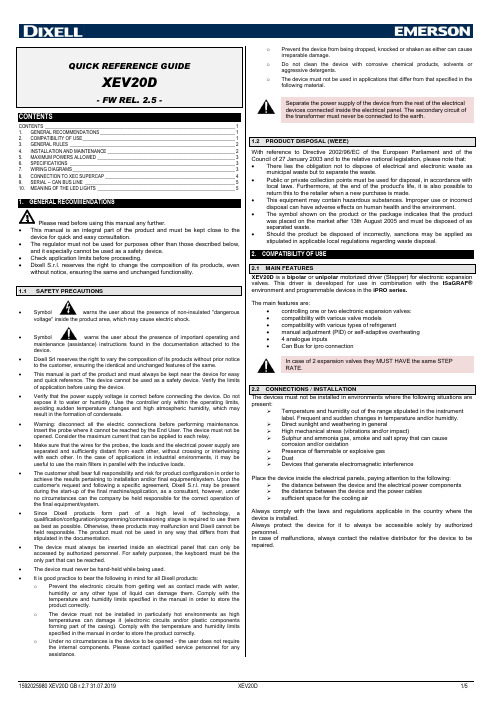
oPrevent the device from being dropped, knocked or shaken as either can cause irreparable damage.o Do not clean the device with corrosive chemical products, solvents or aggressive detergents.oThe device must not be used in applications that differ from that specified in the following material.Separate the power supply of the device from the rest of the electrical devices connected inside the electrical panel. The secondary circuit of the transformer must never be connected to the earth.With reference to Directive 2002/96/EC of the European Parliament and of the Council of 27 January 2003 and to the relative national legislation, please note that: • There lies the obligation not to dispose of electrical and electronic waste asmunicipal waste but to separate the waste. • Public or private collection points must be used for disposal, in accordance withlocal laws. Furthermore, at the end of the product's life, it is also possible to return this to the retailer when a new purchase is made. • This equipment may contain hazardous substances. Improper use or incorrectdisposal can have adverse effects on human health and the environment. • The symbol shown on the product or the package indicates that the productwas placed on the market after 13th August 2005 and must be disposed of as separated waste. • Should the product be disposed of incorrectly, sanctions may be applied asstipulated in applicable local regulations regarding waste disposal.2. COMPATIBILITY OF USEvalves. This driver is developed for use in combination with the ISaGRAF® environment and programmable devices in the iPRO series.The main features are:• controlling one or two electronic expansion valves: • compatibility with various valve models • compatibility with various types of refrigerant • manual adjustment (PID) or self-adaptive overheating • 4 analogue inputs • Can Bus for ipro connectionIn case of 2 expansion valves they MUST HAVE the same STEP RATE.present:➢ Temperature and humidity out of the range stipulated in the instrumentlabel. Frequent and sudden changes in temperature and/or humidity. ➢ Direct sunlight and weathering in general ➢ High mechanical stress (vibrations and/or impact) ➢ Sulphur and ammonia gas, smoke and salt spray that can causecorrosion and/or oxidation ➢ Presence of flammable or explosive gas ➢ Dust ➢ Devices that generate electromagnetic interferencePlace the device inside the electrical panels, paying attention to the following:➢ the distance between the device and the electrical power components ➢ the distance between the device and the power cables ➢ sufficient space for the cooling airAlways comply with the laws and regulations applicable in the country where the device is installed.Always protect the device for it to always be accessible solely by authorized personnel.In case of malfunctions, always contact the relative distributor for the device to be repaired.3. GENERAL RULESComply with the following recommendations during the installation process in order to prevent the device from malfunctioning. ➢ Separate the signal cables from the power cables (it is recommended to useBELDEN 8772-type shielded cables). ➢ Separate the cables of the analogue inputs from those of the digital inputs andthe serial line cables from the power cables (resistive as well as inductive), in order to prevent malfunction due to electromagnetic interference. ➢ Separate the power of the device from that of the other electrical components. ➢ Never connect the secondary of the supply transformer to the earth. ➢ The low voltage connections must have reinforced insulation.4. INSTALLATION AND MAINTENANCEXEV20D is a slave device, which means that it receives commands from another “master” device; in particular , instructions are given by an iPro controller through a CANBUS (10DIN version) or LAN (4DIN version) connection.Operating parameters are sent by an iPro and then they are stored in a special retentive memory area inside the driver.The necessary parameters for operation are:This memory stores the values of the following parameters:1) valve type (0= disabled valves; 1= both unipolar valves / 2= both bipolarvalves and Wavemode type of command; 18 = both bipolar valves and Normal mode type of command)2) valve 1 step rate (expressed in tens of ms 16-10000) 3) valve 2 step rate (expressed in tens of ms 16-10000) 4) valve 1 maximum number of steps (0-8500) 5) valve 2 maximum number of steps (0-8500) 6) valve 1 movement current (0-100 *10mA) 7) valve 2 movement current (0-100 *10mA) 8) valve 1 maintenance current (1-100 *10mA) 9) valve 2 maintenance current (1-100 *10mA)10) unipolar valve 1 configuration (Current/ no current with valve in position– adjustment steps expressed in whole steps/half steps)11) unipolar valve 2 configuration (Current/ no current with valve in position– adjustment steps expressed in whole steps/half steps)Whenever the master device (iPro) tells the driver a new value for one of the aforementioned parameters, the driver itself proceeds with thecomplete closure of the valve.The XEV20D drivers issued by Dixell are tested but not configured: this means that the parameters in the fla sh memory are set to a default value (specifically, the “valve type” parameter = 0).Read carefully the table below to learn how to connect valves produced by different OEMs:5-WIRE VALVES (UNIPOLAR)The maximum distance between a XEV valve driver and the valve must not exceed 10 meters ; shielded cables with a section greater than or equal to 0.325 mm² (AWG22) must be used.At power-on XEV20D reads the parameters in the flash memory. At this point: • If “valve type” = 0, no action is taken on the val ve and both “PWR ON” and“ALARM” leds remain on steady.• If “valve type” ≠ 0, the driver itself commands the complete closure of the valve. During this phase the “Close” led blinks .Once the valve has been closed (the “Close” led remains on steady), the driver waits to receive instructions from iPro.During the first connection, the replacement of a valve body or the first test of a unit, it is necessary to follow the procedure below:1. Disable any unit adjustment;2. Cut off power to the whole unit;3. Disconnect the connector dedicated to valve wiring.4.In case the connection of the valve body involves the modification of its operating parameters, proceed as follows:a. Power the unit, disconnecting the body valve from XEV20D.b. Set the new parameters of the valve using the iPro application.c. Remove power from the unit.5. Connect the body valve to XEV20D driver.6. Power the unit.Valve wires must not be connected or disconnected, whenever the driver is powered. This action may damage the driver and the valve windings.“PWR ON” and “ALARM” leds“Open” and “Close” ledsValve 1 and 2 terminals5. MAXIMUM POWERS ALLOWEDXEV20D can control a large variety of motorized valves. The table below shows the maximum current values that the valve windings can absorb. Select the transformer that is suitable for the application on the basis of that shown in the table. The type of DIXELL transformer to use is indicated for every operating mode.NOTE: carefully read the technical manual supplied by the manufacturer of the valve body before using the driver in order to prevent changing the data provided by the manufacturers of the valves, and verify that the required currents are lower than those shown in the table below in order to prevent damaging the control module. CONFIGURATION ONE VALVE TWO VALVES DRIVE MODE Entire step Entire stepT Y P E O F V A L V EBIPOLAR Valves(4 wires) Current 0.9A max → TF20DCurrent 0.9A maxper valve → TF40DUNIPOLAR valves(5-6 wires) Current 0.33A max → TF20DCurrent 0.33A maxper valve → TF20D6. SPECIFICATIONS6.1 ANALOGUE INPUTSNumber of inputs:4Type of analogue input: (configurable via software parameter)Inputs 1 and 2:NTC (-50T110°C; 10KΩ at 25°C) PTC (-55T115°C; 990Ω at 25°C) PT1000 (-50T100°C ; 1K Ω at 0°C) Inputs 3 and 4:NTC (-50T110°C; 10KΩ at 25°C) PTC (-55T115°C; 990Ω at 25°C) PT1000 (-50T100°C ; 1K Ω at 0°C)In voltage: 0 to 5V (input resistance 3.7KΩ) In curren t: 4 to 20 mA (input resistance 100Ω) Precision (at 25°C): NTC, PTC, PT1000: ±1°C 0-5V: ±100mV 4-20mA ±0.30mAMeasurement and adjustment field: -50°C ÷ 110°C (-58 °F ÷ 230°F) NTC probe -50°C ÷ 150°C (32 °F ÷ 302°F) PTC probe -50°C ÷ 100°C (32 °F ÷ 212°F) PT1000 probe -0 bar ÷ 50 bar (0 psi ÷ 302 psi) pressure probe Resolution0.1 °C 1 °F 0.1 bar6.2 DIGITAL INPUTSDigital inputs can be configured via software as digital inputs:Type:(configurable via softwareparameter)Non opto-insulated potential free contactMax cable length 10mNumber of inputs: 4 Notes: Do not use live contacts in order to prevent theinstrument from being damaged.6.3 ELECTRICAL SPECIFICATIONSPower Supply: 24Vac/dc -10% ÷ 10%, 50/60Hz Consumption: Max. 10VA Connectors: Molex connectors with wiring for low voltage (powersupply, probes, digital inputs, analogue outputs) STELVIO quick coupling screw connectors for low voltage (LAN)STELVIO quick coupling screw connectors for relay outputs (250Vac, 6A max)6.4 PLASTIC CONTAINERAssembly:On a DIN rail (EN 50022, DIN 43880)Fastened with screws via the removable plastic flaps.Material:PC-ABS Thermoplastic Self-extinguishing: V0 (UL94) Comparative Tracking Index (CTI): 300V Colour:Black Frontal protection: IP206.5 OPERATING CONDITIONSOperating temperature: -10°C ÷ 60°C Storage temperature: -30°C ÷ 85°C Relative humidity: 20% ÷ 85%7. WIRING DIAGRAMS7.1 VERSION FOR ONE VALVE7.2 VERSION FOR TWO VALVES16 17 Battery +In gnd16 17 Battery +In gndIf the power supply is Vdc, follow the polarity as shown below:Pin 1 = + Pin 7 = -If the power supply is Vdc, follow the polarity as shown below:Pin 1 = + Pin 7 = -7.4.1 Temperature probes (NTC and PTC)2-row sensors that do not require polarity to be respected.Each sensor must be connected through one of the inputs (from Pb1 to Pb10) and the common (PbC) as shown in the diagram below.7.4.2 Pressure transducers and current probes (4 - 20 mA)2-row sensors that require +12Vdc power supply.Each sensor must be connected through one of the inputs (from Pb1 to Pb10) and the power supply (+12V) as shown in the diagram below.3-row sensors that require +5Vdc power supply.8.2 CONNECTION TO THE XEV20D DRIVER WITH TWO CONNECTED VALVES9.SERIAL -- CAN BUS LINEThe device can communicate via CAN Bus serial only once an appropriate module address has been set. The address is set by the dip-switch, named Address, according to the following drawing:The address is set in binary mode. Eachselector has an increasing weight, in thefigure the set address is:1 x 1 = 12 x 0 = 04 x 1 = 48 x 1 = 8➔1+4+8=13NOTE: To set properly the ISaGRAF® software, refer to the documentation on https://www.ipro.academy website.10.MEANING OF THE LED LIGHTSThe following table illustrates LED light operation.LED MODE MEANINGPWR ON On The instrument is powered correctlyALARM On There is an alarmTX/RX Blinking CAN Bus or LAN activity, communication enabledTX/RX On No linkOPEN V1 Blinking Valve 1 in opening mode OPEN V1 On Valve 1 fully open CLOSE V1 Blinking Valve 1 in closing mode CLOSE V1 On Valve 1 fully closed OPEN V2 Blinking Valve 2 in opening mode OPEN V2 On Valve 2 fully open CLOSE V2 Blinking Valve 2 in closing mode CLOSE V2 On Valve 2 fully closed。
VISHAY BYG20 说明书

IR=0.5A, iR=0.125A 500 400 300 200 100 0 0 0.2 0.4 0.6 0.8 1.0 Tamb= 125°C 100°C 75°C 50°C 25°C
94 9340
Tamb – AmbF – Forward Current ( A )
Document Number 86009 Rev. 3, 24-Jun-98
www.vishay.de • FaxBack +1-408-970-5600 1 (5)
BYG20
Vishay Telefunken Electrical Characteristics
Tj = 25_C Parameter Forward voltage g Reverse current Reverse recovery time Test Conditions IF=1A IF=1.5A VR=VRRM VR=VRRM, Tj=100°C IF=0.5A, IR=1A, iR=0.25A Type Symbol VF VF IR IR trr Min Typ Max 1.3 1.4 1 10 75 Unit V V mA mA ns
Figure 6. Thermal Response
Document Number 86009 Rev. 3, 24-Jun-98
www.vishay.de • FaxBack +1-408-970-5600 3 (5)
BYG20
Vishay Telefunken Dimensions in mm
It is the policy of Vishay Semiconductor GmbH to 1. Meet all present and future national and international statutory requirements. 2. Regularly and continuously improve the performance of our products, processes, distribution and operating systems with respect to their impact on the health and safety of our employees and the public, as well as their impact on the environment. It is particular concern to control or eliminate releases of those substances into the atmosphere which are known as ozone depleting substances ( ODSs ). The Montreal Protocol ( 1987 ) and its London Amendments ( 1990 ) intend to severely restrict the use of ODSs and forbid their use within the next ten years. Various national and international initiatives are pressing for an earlier ban on these substances. Vishay Semiconductor GmbH has been able to use its policy of continuous improvements to eliminate the use of ODSs listed in the following documents. 1. Annex A, B and list of transitional substances of the Montreal Protocol and the London Amendments respectively 2 . Class I and II ozone depleting substances in the Clean Air Act Amendments of 1990 by the Environmental Protection Agency ( EPA ) in the USA 3. Council Decision 88/540/EEC and 91/690/EEC Annex A, B and C ( transitional substances ) respectively. Vishay Semiconductor GmbH can certify that our semiconductors are not manufactured with ozone depleting substances and do not contain such substances.
道纳尔制造公司产品说明书:3寸直径滑动轮汇编

DORNER MFG. CORP.
580 Industrial Drive, PO Box 20 Hartland, WI 53029-0020 USA
USA TEL 1-800-397-8664 (USA) FAX 1-800-369-2440 (USA)
Outside the USA: TEL 1-414-367-7600, FAX 1-414-367-5827
DORNER
Arnold-Sommerfeld-Ring 2 D-52499 Baesweiler
Germany TEL (02401) 80 52 90 FAX (02401) 80 52 93
DMC-PD1197
Printed in U.S.A.
3″ Diameter Idler Pulleys
Supplement to Catalog 31MP-1-1.0 (Parts, Assembly and Maintenance Manual for 3100 Series Flat Belt Conveyors[with Metric Fasteners]) or Catalog 310P-2 (Parts, Assembly and Maintenance Manual for 3100 Series Conveyors)
Part Description
3″ (76 mm) Dia. Idler Ass’y, 4″ (95 mm) 3″ (76 mm) Dia. Idler Ass’y, 5″ (127 mm) 3″ (76 mm) Dia. Idler Ass’y, 6″ (152 mm) 3″ (76 mm) Dia. Idler Ass’y, 8″ (203 mm) 3″ (76 mm) Dia. Idler Ass’y, 10″ (254 mm) 3″ (76 mm) Dia. Idler Ass’y, 12″ (305 mm) 3″ (76 mm) Dia. Idler Ass’y, 18″ (457 mm) 3″ (76 mm) Dia. Idler Ass’y, 24″ (610 mm) 3″ (76 mm) Dia. Idler Ass’y, 30″ (762 mm) 3″ (76 mm) Dia. Idler Ass’y, 36″ (915 mm) 3″ (76 mm) Dia. Idler Ass’y, 40″ (1016 mm) Retaining Ring Ball Bearing Aluminum Pulley Tube, 4″ (95 mm) Aluminum Pulley Tube, 5″ (127 mm) Aluminum Pulley Tube, 6″ (152 mm) Aluminum Pulley Tube, 8″ (203 mm) Aluminum Pulley Tube, 10″ (254 mm) Aluminum Pulley Tube, 12″ (305 mm) Aluminum Pulley Tube, 18″ (457 mm) Aluminum Pulley Tube, 24″ (610 mm) Aluminum Pulley Tube, 30″ (762 mm) Aluminum Pulley Tube, 36″ (916 mm) Aluminum Pulley Tube, 40″ (1016 mm)
RANGER 3 三相操作员手册说明书

RANGER ®3 PHASEFor Machines with Code Number 11619IM10030November, 2010Safety Depends on YouLincoln arc welding and cutting equipment is designed and built with safety in mind. However,your overall safety can be increased by proper installation ...and thoughtful operation on your part.DO NOT I NSTAL L,O PERATE O R REPAI R THI S EQ UI PM ENT W I THO UT READ-I N G TH I S M ANU AL AN D TH E SAFETY PRECAUTI O NS CO N-TAI NED THROUGHO UT.And,most importantly, think before you act and be careful.Copyright © Lincoln Global Inc.SECTION A:WARNINGSC ALIFORNIA PROPOSITION 65 WARNINGSWARNING: This product, when used for welding or cutting, produces fumes or gases which contain chemicals known to the State of California to cause birth defects and, in some cases, cancer. (California Health & Safety Code § 25249.5 et seq.)ARC WELDING CAN BE HAZARDOUS. PROTECTYOURSELF AND OTHERS FROM POSSIBLE SERIOUS INJURY OR DEATH. KEEP CHILDREN AWAY.PACEMAKER WEARERS SHOULD CONSULT WITH THEIR DOCTOR BEFORE OPERATING.Read and understand the following safety highlights. For additional safety information, it is strongly recommended that you purchase a copy of “Safety in Welding & Cutting - ANSI Standard Z49.1” from the American Welding Society, P.O. Box 351040, Miami, Florida 33135 or CSA Standard W117.2-1974. A Free copy of “Arc Welding Safety” booklet E205 is available from the Lincoln Electric Company, 22801 St. Clair Avenue, Cleveland, Ohio 44117-1199.BE SURE THAT ALL INSTALLATION, OPERATION,MAINTENANCE AND REPAIR PROCEDURES ARE PERFORMED ONLY BY QUALIFIED INDIVIDUALS.FOR ENGINE POWERED EQUIPMENT.1.a.Turn the engine off before troubleshootingand maintenance work unless themaintenance work requires it to be running.1.b.Operate engines in open, well-ventilated areas or vent the engineexhaust fumes outdoors. 1.c.Do not add the fuel near an open flame weldingarc or when the engine is running. Stop the with hot engine parts and igniting. Do not spill fuel when filling tank. If fuel is spilled, wipe it up and do not start engine until fumes have been eliminated.1.d. Keep all equipment safety guards, coversand devices in position and in good repair.Keep hands, hair, clothing and tools away from V-belts, gears, fans and all other moving parts when starting, operating or repairing equipment.1.e.In some cases it may be necessary to remove safety guards toperform required maintenance. Remove guards only when necessary and replace them when the maintenance requiring their removal is complete. Always use the greatest care when working near moving parts. 1.f. Do not put your hands near the engine fan. Do not attempt tooverride the governor or idler by pushing on the throttle control rods while the engine is running. 1.g.To prevent accidentally starting gasoline engines while turningthe engine or welding generator during maintenance work,disconnect the spark plug wires, distributor cap or magneto wire as appropriate. 1.h.To avoid scalding, do not remove the radiatorpressure cap when the engine is hot.ELECTRIC ANDMAGNETIC FIELDS MAY BE DANGEROUS2.a.Electric current flowing through any conductorcauses localized Electric and Magnetic Fields (EMF).Welding current creates EMF fields around welding cables and welding machines 2.b.EMF fields may interfere with some pacemakers, andwelders having a pacemaker should consult their physician before welding. 2.c.Exposure to EMF fields in welding may have other health effectswhich are now not known. 2.d.All welders should use the following procedures in order tominimize exposure to EMF fields from the welding circuit:2.d.1.Route the electrode and work cables together - Securethem with tape when possible.2.d.2.Never coil the electrode lead around your body.2.d.3.Do not place your body between the electrode and workcables. If the electrode cable is on your right side, the work cable should also be on your right side.2.d.4.Connect the work cable to the workpiece as close as pos-sible to the area being welded.2.d.5.Do not work next to welding power source.SAFETYWELDING OUTPUT CAbLESWith the engine off, connect the electrode and work cables to the studs provided. These connections should be checked periodically and tightened if neces-sary. Loose connections will result in overheating of the output studs.When welding at a considerable distance from the welder, be sure you use ample size welding cables. Listed below are copper cable sizes recommended for the rated current and duty cycle. Lengths stipulated are the distance from the welder to work and back to the welder again. Cable sizes are increased for greater lengths primarily for the purpose of minimizing cable voltage drop.ANGLE OF OPERATIONInternal combustion engines are designed to run in a level condition which is where the optimum perfor-mance is achieved. The maximum angle of operation for the engine is 15 degrees from horizontal in any direction. If the engine is to be operated at an angle, provisions must be made for checking and maintain-ing the oil at the normal (FULL) oil capacity in the crankcase in a level condition.When operating at an angle, the effective fuel capacity will be slightly less than the specified 12 Gal. (45 L). LIFTINGThe RANGER® 3 PHASE weighs approximately 587lbs. (266.3kg) with a full tank of gasoline. A lift bail is mounted to the machine and should always be used when lifting the machine.ADDITIONAL SAFETY PRECAUTIONAt higher altitudes, Welder output de-rating may be necessary. For maximum rating, de-rate the welder output 3.5% for every 1000 ft. (305m) above 3000 ft. (914m). If operation willconsistently be at altitudes above 5,000 ft. (1525m), a carburetor jet designed for high altitudes should be installed. This will result in better fuel economy, cleaner exhaust and longer spark plug life. It will not give increased power. Contact your local authorized engine service shop for high altitude jet kits that are available from the engine manufacturer.Do not operate with a high altitude jet installed at altitudes below 5000 ft. (1525m). This will result in the engine running too lean and result in higher engine operating temperatures which can shorten engine life.------------------------------------------------------------------------MUFFLER OUTLET PIPEUsing the clamp provided secure the outlet pipe to the outlet tube with the pipe positioned such that it will direct the exhaust in the desired direction. Tighten using a 9/16” socket or wrench.TABLE lllELECTRICAL DEVICE USE WITH THE RANGER® 3 PHASE.Type Common Electrical Devices Possible Concerns ResistiveHeaters, toasters, incandescent NONElight bulbs, electric range, hot pan, skillet, coffee maker.CapacitiveTV sets, radios, microwaves, Voltage spikes or high voltageappliances with electrical control.regulation can cause the capacitative elements to fail. Surge protection,transient protection, and additional loading is recommended for 100%fail-safe operation. DO NOT RUN THESE DEVICES WITHOUT ADDI-TIONAL RESISTIVE TYPE LOADS.InductiveSingle-phase induction motors, These devices require large drills, well pumps, grinders, small current inrush for starting.refrigerators, weed and hedge Some synchronous motors may trimmersbe frequency sensitive to attain maxi-mum output torque, but they SHOULD BE SAFE from any frequency induced failures.Capacitive/InductiveComputers, high resolution TV sets,An inductive type line condition-complicated electrical equipment.er along with transient and surge pro-tection is required, and liabilities still exist. DO NOT USE THESE DEVICES WITH A RANGER® 3PHASEThe Lincoln Electric Company is not responsible for any damage to electrical components improperly connected to the RANGER® 3PHASE.MOTOR STARTINGMost 1.5 hp AC single phase motors can be started if there is no load on the motor or other load connected to the machine,since the full load current rating of a 1.5 hp motor is approxi-mately 20 amperes (10 amperes for 240 volt motors). The motor may be run at full load when plugged into only one side of the duplex receptacle. Larger motors through 2 hp can be run provided the receptacle rating as previously stated is not exceeded. This may necessitate 240V operation only.The 480 volt 3 phase output of the RANGER 3 PHASE is capa-ble of running most 480VAC 3 phase motors up to 10HP. A 10HP motor must be started with no load on the motor and no other load connected to the machine, since the full load current of a 10HP 480VAC 3 phase motor is approximately 12.5 amps.Refer to the reconnect phase output to any load, the ground at the 3 phase receptacle is NOT the neutral of 3 phase connec-tion, and should under no circumstance be connected to the neutral of any 3 phase load.1.Install a double pole, double throw switch betweenthe power company meter and the premises dis-connect.Switch rating must be the same or greater than the customer’s premises disconnect and service over-current protection.2.Take necessary steps to assure load is limited tothe capacity of the RANGER® 3 PHASE by installing a 40 amp 240V double pole circuit break-er. Maximum rated load for the 240V auxiliary is 40 amperes. Loading above 40 amperes will reduce output voltage below the allowable -10% of rated voltage which may damage appliances or other motor-driven equipment.3.Install a 50 amp 120/240V plug (NEMA type 14-50)to the Double Pole Circuit Breaker using No. 8, 4 conductor cable of the desired length. (The 50 amp 120/240V plug is available in the optional plug kit.)4.Plug this cable into the 50 amp 120/240V recepta-cle on the RANGER® 3 PHASE case front.Diameter Wire Speed Approximate (in.) Range In./Min. Current Range .03075 - 30050A to 130A.035100 - 25090A to 175AhOW TO USE TROUbLEShOOTING GUIDEJapaneseChineseKoreanArabicREAD AND UNDERSTAND THE MANUFACTURER’S INSTRUCTION FOR THIS EQUIPMENT AND THE CONSUMABLES TO BE USED AND FOLLOW YOUR EMPLOYER’S SAFETY PRACTICES.SE RECOMIENDA LEER Y ENTENDER LAS INSTRUCCIONES DEL FABRICANTE PARA EL USO DE ESTE EQUIPO Y LOS CONSUMIBLES QUE VA A UTILIZAR, SIGA LAS MEDIDAS DE SEGURIDAD DE SU SUPERVISOR.LISEZ ET COMPRENEZ LES INSTRUCTIONS DU FABRICANT EN CE QUI REGARDE CET EQUIPMENT ET LES PRODUITS A ETRE EMPLOYES ET SUIVEZ LES PROCEDURES DE SECURITE DE VOTRE EMPLOYEUR.LESEN SIE UND BEFOLGEN SIE DIE BETRIEBSANLEITUNG DER ANLAGE UND DEN ELEKTRO-DENEINSATZ DES HERSTELLERS. DIE UNFALLVERHÜTUNGSVORSCHRIFTEN DES ARBEITGEBERS SIND EBENFALLS ZU BEACHTEN.JapaneseChineseKoreanArabicLEIA E COMPREENDA AS INSTRUÇÕES DO FABRICANTE PARA ESTE EQUIPAMENTO E AS PARTES DE USO, E SIGA AS PRÁTICAS DE SEGURANÇA DO EMPREGADOR.。
TR-220 多功能测试设备数据手册说明书

status (Air, Ground, Alert, SPI), Mode S/Mode A 4096 code compare
airborne velocity), latitude/longitude, N/S velocity, E/W velocity, Flight
(automatic mode) Mode S Surveillance Altitude (DF4) – Mode S altitude, percent reply,
TCAS
• Test set allows storage of 10 intruder scenarios, to simplify TCAS testing • Allows simulation of ATCRBS or Mode S intruder • User selection of velocity, starting distance, starting altitude, and vertical speed • Measures UUT power and frequency
surface position)
Mode S Surveillance Short (DF0) – Mode S address, vertical status
Transmits TIS data for four intruder aircraft
(Air, ground), percent reply, decoded country code, decoded tail
and receiver sensitivity (dBm) Decodes and displays Flight I.D.
Decodes and displays Mode S address in Octal and Hex
ON DEMAND Custom DVR 3-Device Universal Remote说明书

Use the keypad (0 ~ 9)to directly select the channels (e.g., 09 or 031).
ON DEMAND Custom DVR
3 Device
User Guide Overview
The ON DEMAND Custom DVR 3Device universal remote will control up to three home entertainment devices, including a Digital Video Recorder enabled Cable Box. The remote control requires installing two (2) new AA batteries (included) and some easy programming to control your devices. For best results, please read and perform all instructions listed here. Also, keep this guide for future reference.
2. On the remote control, press a device key once (i.e., AUX or TV).
NOTE: Use the AUX key to program control of an Audio Amplifier or Receiver, a DVD Player, a HomeTheater-In-A-Box Device, a PVR (or DVR), or a VCR.
PDA-TR34文件中文

医疗保健产品生产和检测用隔离系统的设计和验证PDA 技术报告34号2001年9/10月1.0 引言1.1前言近年来,隔离技术迅速出现,作为一种可供选择的人造环境广泛应用于多种医疗保健产品的生产和检测。
隔离系统的性能特征使其可以很理想的用于无菌产品的制备,以及活性物质的隔离。
其它的应用还有临床准备、无菌散装药品/生物制剂、无菌细胞毒素物质的制备,以及无菌检测。
该技术目前没有权威的应用和验证指导,而且关于“隔离系统”和“阻隔器”的概念严重混淆,这是PDA发布此文件的根本动机。
本文件是由美国PDA、日本PDA、A3P、注射药物协会、和德国代表组成的国际委员会制定的。
本文件可用作指导原则;并不作为强制或暗示的标准。
1.2范围本技术报告给出了在医疗保健产品制造工业的生产、开发、检测中广泛应用隔离技术的基本要求。
本技术报告不仅包括产品的无菌保证,也包括了危险物料的隔离。
术语表〔附录A〕是本技术报告的一个重要组成部分。
医疗保健行业目前没有一整套关于隔离技术的定义。
委员会认为,为了阐述有用的技术信息,我们必须保证读者在应用该技术报告时没有概念的混淆。
委员会也承认在世界的一些地区,在临床制药设备中经过处理的环境条件都叫做“隔离系统”,这些装置与本文定义的隔离系统有着共同的基本特征,然而,它们与现在医疗保健工业中使用的、用于无菌产品的生产和检测的隔离系统有着显著区别。
本技术报告不适用于不符合本文规定和解释的基本标准的设备。
1.3关键定义建立清晰的划分标准来区分是否是隔离系统对于理解本文至关重要。
PDA建议以下关于隔离系统的定义应被全世界医疗保健行业采纳:隔离系统是密封的或者有微生物过滤系统〔高效过滤系统HEPA〕提供空气并且可以自净化〔1〕。
当密闭时,仅使用已净化过的内部外表或使用快速传递通道进行物料传递。
当打开时,仅允许物料通过特定的并已经过设计和验证的开口进行进出传递,以排出污染的传递。
它可被用于无菌操作时隔离活性混合物的或者同时用于灭菌处理和隔离。
- 1、下载文档前请自行甄别文档内容的完整性,平台不提供额外的编辑、内容补充、找答案等附加服务。
- 2、"仅部分预览"的文档,不可在线预览部分如存在完整性等问题,可反馈申请退款(可完整预览的文档不适用该条件!)。
- 3、如文档侵犯您的权益,请联系客服反馈,我们会尽快为您处理(人工客服工作时间:9:00-18:30)。
Vishay General SemiconductorBYG20D thru BYG20JDocument Number: Ultrafast Avalanche SMD RectifierFEATURES•Low profile package•Ideal for automated placement •Glass passivated junction •Low reverse current •Soft recovery characteristics•Ultrafast reverse recovery time•Meets MSL level 1, per J-STD-020C, LF max peak of 260 °C •Solder Dip 260 °C, 40 seconds•Component in accordance to RoHS 2002/95/EC and WEEE 2002/96/ECTYPICAL APPLICATIONSFor use in high frequency rectification of power supply,inverters, converters and free-wheeling diodes for consumer, automotive and telecommunication.MECHANICAL DATA Case: DO-214AC (SMA)Epoxy meets UL 94V-0 flammability ratingTerminals: Matte tin plated leads, solderable per J-STD-002B and JESD22-B102DE3 suffix for commercial grade, HE3 suffix for high reliability grade (AEC Q101 qualified)Polarity:Color band denotes the cathode endDO-214AC (SMA)MAJOR RATINGS AND CHARACTERISTICSI F(AV) 1.5 A V RRM 200 V to 600 VI FSM 30 A I R 1.0 µA V F 1.4 V t rr 75 ns E R 20 mJ T j max.150 °CMAXIMUM RATINGS (T A = 25°C unless otherwise noted)PARAMETER SYMBOLBYG20D BYG20G BYG20J UNITDevice marking codeBYG20D BYG20G BYG20J Maximum repetitive peak reverse voltage V RRM 200400600V Average forward currentI F(AV) 1.5A Peak forward surge current 10 ms single half sine-wave superimposed on rated load I FSM 30A Pulse energy in avalanche mode,non repetitive (inductive load switch off)I (BR)R = 1 A, T j = 25 °CE R 20mJ Operating junction and storage temperature rangeT J , T STG- 55 to + 150°C Document Number: 88958Vishay General SemiconductorBYG20D thru BYG20JNote:(1) Pulse test: 300 µs pulse width, 1 % duty cycleNotes:(1) Mounted on epoxy-glass hard tissue(2) Mounted on epoxy-glass hard tissue, 50 mm 2 35 µm Cu (3) Mounted on Al-oxide-ceramic (Al 2O 3), 50 mm 2 35 µm CuNote:(1) Automotive grade AEC Q101 qualifiedRATINGS AND CHARACTERISTICS CURVES (T A = 25 °C unless otherwise noted)ELECTRICAL CHARACTERISTICS (T A = 25°C unless otherwise noted)PARAMETERTEST CONDITIONSSYMBOLBYG20DBYG20GBYG20JUNIT Maximuminstantaneousforward voltage (1)at I F = 1 AI F = 1.5 AT j = 25 °C V F 1.31.4VMaximum DC reverse currentat V R = V RRMT j = 25 °C T j = 100 °CI R 110µA Maximum reverse recovery time I F = 0.5 A, I R = 1.0 A,I rr = 0.25 A t rr75nsTHERMAL CHARACTERISTICS (T A = 25°C unless otherwise noted)PARAMETERSYMBOL BYG20DBYG20G BYG20JUNIT Typical thermal resistance - Junction lead T L = const.R θJL 25°C/W Typical thermal resistance - Junction AmbientR θJA150 (1) 125 (2) 100 (3)°C/WORDERING INFORMATION (Example)PREFERRED P/N UNIT WEIGHT (g)PACKAGE CODEBASE QUANTITYDELIVERY MODE BYG20D-E3/TR 0.064TR 18007" Diameter Plastic T ape & Reel BYG20D-E3/TR30.064TR3750013" Diameter Plastic T ape & Reel BYG20DHE3/TR (1)0.064TR 18007" Diameter Plastic T ape & Reel BYG20DHE3/TR3 (1)0.064TR3750013" Diameter Plastic T ape & ReelFigure 1. Forward Current vs. Forward VoltageFigure 2. Max. Average Forward Current vs. Ambient TemperatureDocument Number: BYG20D thru BYG20JVishay General SemiconductorFigure 3. Reverse Current vs. Junction Temperature Figure 4. Max. Reverse Power Dissipation vs. Junction Temperature Figure 5. Diode Capacitance vs. Reverse VoltageFigure 6. Reverse Recovery Time vs. Forward CurrentFigure 7. Reverse Recovery Charge vs. Forward CurrentFigure 8. Thermal ResponseBYG20D thru BYG20JVishay General SemiconductorPACKAGE OUTLINE DIMENSIONS in inches (millimeters) Document Number: 88958Legal Disclaimer NoticeVishayNoticeSpecifications of the products displayed herein are subject to change without notice. Vishay Intertechnology, Inc., or anyone on its behalf, assumes no responsibility or liability for any errors or inaccuracies.Information contained herein is intended to provide a product description only. No license, express or implied, by estoppel or otherwise, to any intellectual property rights is granted by this document. Except as provided in Vishay's terms and conditions of sale for such products, Vishay assumes no liability whatsoever, and disclaims any express or implied warranty, relating to sale and/or use of Vishay products including liability or warranties relating to fitness for a particular purpose, merchantability, or infringement of any patent, copyright, or other intellectual property right. The products shown herein are not designed for use in medical, life-saving, or life-sustaining applications. Customers using or selling these products for use in such applications do so at their own risk and agree to fully indemnify Vishay for any damages resulting from such improper use or sale.。