printed quadrifilar helix antenna with intergrated feed network
Helix-stabilized Fv (hsFv) antibody fragments substituting the constant domains of a Fab fr
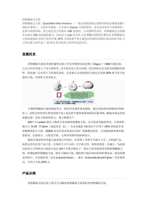
Helix-stabilized Fv (hsFv)Antibody Fragments:Substituting the Constant Domains of a Fab Fragment for a Heterodimeric Coiled-coil DomainKatja M.Arndt 1,2,Kristian M.Mu Èller 1,2and Andreas Plu Èckthun 1*1Biochemisches InstitutUniversitaÈt Zu Èrich Winterthurerstr.1908057ZuÈrich,Switzerland 2Department of Molecular andCell Biology,University of California,229Stanley Hall Berkeley,CA 94720-3206,USAAntibody Fv fragments would in principle be useful for a variety of bio-technological applications because of their small size and the possibility to produce them in relatively large amounts in recombinant form;how-ever,their limited stability is a drawback.To solve this problem,both domains are usually fused via a peptide linker to form a single-chain Fv (scFv)fragment,but in some cases this leads to a dimerization.We pre-sent an alternative format for stabilizing antibody Fv fragments.The C H 1and C L domain of the Fab fragment were replaced with a heterodimeric coiled coil (WinZip-A2B1),which had previously been selected using a protein-fragment complementation assay in Escherichia coli .This new anti-body format was termed helix-stabilized Fv fragment (hsFv),and was compared to the corresponding Fv,Fab and single-chain Fv format.Bac-terial growth and expression of the hsFv was signi®cantly improved compared to the Fab fragment.The hsFv fragment formed a heterodimer of heavy and light chain with the expected molecular mass,also under conditions where the scFv fragment was predominantly dimeric.The hsFv fragment was signi®cantly more stable than the Fv fragment,and nearly as stable as the scFv fragment under the conditions used (80nM protein concentration).Thus,the format of a helix-stabilized Fv (hsFv)fragment can be a useful alternative to existing recombinant antibody formats,especially in cases where poor expression of Fab fragments or multimerization of scFv fragments is a problem.#2001Academic PressKeywords:leucine zipper;antibody engineering;protein stability;protein design;protein engineering*Corresponding authorIntroductionImmunoglobulin Fv fragments are the smallest functional units of antibodies still containing the complete antigen-binding site.They are heterodi-mers of the heavy-chain variable domain (V H )and the light-chain variable domain (V L ).Their rela-tively small size,the ability to produce them in functional form in the periplasm of Escherichia coli ,1as well as their potential use in immunodiagnosticsand immunotherapy makes them an interesting starting point for protein engineering.However,Fv fragments are of limited stability due to dissociation of the two chains.Dissociation constants of 10À6M to 10À9M have been measured.2±5Therefore,different ways have been established to enforce the association of the two domains.In the Fab fragment,which in addition to the variable domains comprises the ®rst constant domains of the light and heavy chain (C H 1and C L ),the interaction between both chains is signi®-cantly improved.A further method to stabilize Fv fragments is the covalent linkage between both chains.This can be achieved by a ¯exible geneti-cally encoded linker connecting V L and V H ,result-ing in a so-called single-chain Fv fragment (scFv).6±8Alternatively,a covalent linkage can be achieved by the formation of a disul®de bridge between the two chains by introducing two engin-eered cysteine residues,resulting in aso-calledPresent address:K.M.Arndt and K.M.MuÈller,Institut fuÈr Biologie,Universita Èt Freiburg,Scha Ènzlestr.1,79104Freiburg,Germany.Abbreviations used:dsFv,disul®de-stabilized Fv fragment;hsFv,helix-stabilized Fv fragment;scFv,single-chain Fv fragment.E-mail address of the corresponding author:plueckthun@biocfebs.unizh.chdoi:10.1006/jmbi.2001.4915available online at on J.Mol.Biol.(2001)312,221±2280022-2836/01/010221±8$35.00/0#2001Academic Pressdisul®de-stabilized Fv fragment (dsFv).8,9The last two strategies can also be combined.10However,all these formats have advantages and disadvantages,and the method of choice depends highly on the application.The Fab fragment often expresses at signi®cantly lower yield of functional protein compared with the Fv fragment,11even though the absolute yield depends strongly on the particular sequence of the antibody.In the dsFv,the additional cysteine residues usually dramati-cally decreases the expression yield in periplasmic expression,which usually requires that dsFv pro-teins are prepared by refolding.8,9Furthermore,the relative spatial orientation of the V H and V L domains is not constant for different antibodies,and can also vary upon antigen binding.12±14The precise orientation is therefore dif®cult to predict,and there may not be a single successful position to place the designed disul®de bridge for all anti-bodies.The scFv,although expressing comparably well in the periplasm of E.coli ,has a tendency to form dimers or even higher aggregates,15±20depending on the linker length and on individual factors within the domains,which are still not well understood.It cannot be excluded that the linker might even directly or indirectly interfere with folding or antigen binding in some scFv fragments,which could be one contributing factor for reduced apparent af®nities and/or reduced percentage of functional molecules of some scFv fragments com-pared with the corresponding Fab fragments 6,7,21,22or Fv fragments.23For most applications a de®ned oligomerization state is necessary,and a good yield of functional protein is desirable.We therefore developed a new format to stabilize Fv fragments which does not require any structural information of the Fv frag-ment,avoids the problem of multimerization,and is as well expressed as Fv or scFv fragments.This was achieved by combining an Fv fragment with a heterodimerization domain in a Fab fragment-like arrangement (Figure 1).Each chain of the antibody fragment is connected via a designed ¯exible linker to one chain of the heterodimerizing domain.We utilized a coiled coil as heterodimerization domain,and therefore we named this stabilized Fv fragment ``helix-stabilized Fv fragment''or brie¯y ``hsFv''.We chose a highly speci®c,heterodimeric coiled coil,named WinZip-A2B1(Table 1),whichFigure 1.Overview of recombinant antibody formats compared in this study.(a)Helix-stabilized Fv fragment (hsFv).In the ®nal construct,the V H domain (blue)is connected via a ¯exible 14amino acid linker to WinZip-A2(cyan),while the V L domain (red)is connected via a similar linker to WinZip-B1(orange)(see also Table 1).The broken lines (grey)symbolize the distance that should be covered by the ¯exible linkers.(b)Overview of the genes encoding the hsFv fragment.Important restrictions sites (see below)are indicated.(c)Fab frag-ment,consisting of the light chain,V L (red)and C L (orange),and the heavy chain,V H (blue)and C H 1(cyan).(d)The Fv fragment,and (e)the single-chain Fv fragment (scFv)are given in the same color code for the variable domain.The broken grey line symbolizes the linker which connects V H with V L .The constructs were modeled based on the PDB structure 1MCP.29The hsFv fragment is encoded in the vector pKA290_H11-A2B1.The starting point for this vector was the vector pHJ290huC,48which expresses a chimeric Fab fragment with the Fv domain from the murine antibody McPC603,and the constant part from the human anti-body 4D5.V H and V L are preceded by a short FLAG tag.49In the ®rst step,the three stabilizing mutations (``H11``)in the heavy chain 28were introduced from the vector pHJ300H1148as a Spe I/Hin dIII fragment.In the next step,the constant domains were exchanged for the helices WinZip-A2and WinZip-B1forming a coiled-coil domain,via the unique restriction sites Kpn I/Sph I for WinZip-A2and A¯II/Hin dIII for WinZip-B1,respectively.The genes for WinZip-A2and WinZip-B1were obtained by PCR from the resulting vectors of a library-versus -library selection using the vec-tors LibA-DHFR[1]and LibB-DHFR[2:I114A],respectively.24,25The amino acid sequence of the linker and the coiled-coil domain is given in Table 1.The scFv fragment of the antibody McPC603with the three mutations in the heavy chain and an N-terminal FLAG-peptide 49is encoded in the vector pLisc_SAFH11(corre-sponding to pLisc_SF 48with the H11set of mutations 28).The single-chain Fv fragment is in the orientation V H -(G 4S)3-V L .The Fv fragment with a FLAG-peptide before the heavy and the light chain and the same mutations in the heavy chain is encoded in the vector pHJ300H11.The vector coding for the corresponding Fab fragment carrying the same mutations in the heavy chain was obtained by combining the Fab vector pHJ290FF,49which expresses the wt-Fab fragment,with the vector pHJ300H11via Spe I/Hin dIII,resulting in the vector pKA290_H11Fab.All vectors are based on pASK2911and pASK30.30we had previously selected from two coiled-coil libraries using an in vivo assay in E.coli.24,25We preferred this coiled coil over designed ones, because we had previously observed that some designed coiled coils,although being highly stable in vitro,are severely degraded during in vivo expression and puri®cation(K.M.A.,unpublished results).WinZip-A2B1had been selected in the cytosol of E.coli,and is therefore known to be metabolically stable and functional in this environ-ment.Furthermore,WinZip-A2B1was selected to be highly heterospeci®c,since the selection system disfavored homodimerization.24Whether WinZip-A2B1also functioned in a periplasmic expression system,i.e.,whether it was transported to the peri-plasm and was resistant against proteases in this environment as well,had to be investigated in order to evaluate its general utility.Therefore,our approach not only demonstrates a new way to stabilize Fv fragments,but at the same time,also validates the general usefulness of WinZip-A2B1as independent heterodimerization module.We have compared the novel hsFv with the corresponding Fv,scFv and Fab fragment regarding expression behavior,yield of functional protein,oligomeriza-tion state and stability.Model systemFor our studies we chose a mutant of the phosphorylcholine-binding antibody fragment McPC603,which was derived from a murine IgA antibody.26This mutant carries three mutations in the heavy chain(P47A,S71A,A72D,numbered according to the new AHo consensus scheme,27 corresponding to sequentially numbered positions P40A,S63A,A64D),which result in better in vivo folding properties,and thus increased yield in functional expression.28This antibody is a particu-larly useful model system to elucidate the advan-tages of our new approach,because we had previously found that the corresponding single-chain Fv fragment can form dimers under certain conditions.15DesignThe linker connecting each variable chain of the antibody with one helix of the heterodimerization domain should be¯exible and suf®ciently long so as not to put any strain on the V H-V L assembly, but at the same time not too long so that the dimerization of the coiled coil might still be able to facilitate dimerization of V H and V L and thereby increase its ing the structure of the Fab fragment of the antibody McPC603(PDB code 1MCP29),we measured the distances between the C termini of V H(Ser149(AHo numbering27),corre-sponding to Ser122in sequential numbering29)and V L(Ala150(AHo),corresponding to Ala115 (sequential))to be40.6AÊ.In order to prevent a forced,sharp bend of the linker,an isosceles tri-angle was constructed with the bottom part of the Fv fragment(C termini)as base and pointing toward the N termini of the helices with an angle of about45 .The resulting distances along this tri-angle from the C terminus of V H or V L,respect-ively,and the N termini of the helices,were estimated to be24AÊto26AÊ(Figure1).The aver-age distance of an amino acid in a peptide chain of extended conformation is 3.34AÊ,in a peptide folded as a b-strand about3.06AÊ,and0.70AÊin a peptide chain folded as a-helix.Thus,a minimum length of seven,eight or32amino acid residues would be required assuming a maximal extended conformation,a b-strand or an a-helix,respect-ively.To account for enough¯exibility,we chose a 14residue-long linker.To prevent genetic instabil-ities we avoided codon repeats in the linker,and chose a different sequence consisting of the amino acids Gly,Ser,Thr,Pro for both linkers(Table1).Cell viability and protein expressionAll constructs(Fv,Fab,hsFv,scFv)were expressed in the same vector,based on earlier versions30in the E.coli strain JM83(Figure1).The growth curves,measured at26 C(Figure2),show no signi®cant difference for all constructs before induction with1mM IPTG.However,cells expres-sing the Fab fragment grew considerably more slowly after induction.At3.5to four hours after induction,they reached a maximal A550nm of only 2.6before starting to lyse as indicated by a decrease in optical density.This is the result of a toxic effect of the expressed product on bacterial physiology,whose exact mechanistic origin has not yet been elucidated.No signi®cant difference inTable1.Sequences of the linker and the coiled coil domain used for the hsFv fragmentAntibody domain Linker a Coiled-coil domain b,cV H-S-GGTSGSTSGTGST-T-V AQ L RER V KT L RAQ N YE L ESE V QR L REQ V AQ L-ASV L-A-GSSTGSSTGPGST-S-V DE L QAE V DQ L QDE N YA L KTK V AQ L RKK V EK L-ASHeptad position d a bc d efg a bc d efg a bc d efg a bc d efg a bc dH Ling to the consensus numbering27),is relatively¯exible and therefore more likely to participate in the linker part.b The last two amino acids of the linker(amino acids S,T),and the®rst amino acid of the coiled-coil domain(S or T,respectively) were designed to form an N-cap for the helix.c The last two amino acids(AS)were included to increase solubility.d The coiled-coil helix has a seven-residue structural repeat,with residues denoted by the same lower-case letter being in equiva-lent positions.Positions a and d(bold and underlined)are located in the interface between the helices.growth was observed between the Fv fragment and the hsFv.Both reached a maximal A 550nm of about 4.2to 4.4at six to 6.5hours after induction.This indicates that the expression of the additional coiled-coil domain has no negative in¯uence on the viability of the bacteria.In contrast,the scFv fragment imposed more stress on the cell,as those cells reached a maximal A 550nm of only 3.6already 4.5to ®ve hours after induction (Figure 2).Protein purification and yieldIn order to purify only functional protein,and at the same time demonstrate antigen binding,we used a hapten-af®nity puri®cation,as described previously.15,31A washing step with 1M NaCl was added to increase purity,and no impurities were observed in SDS-PAGE (Figure 3).All con-structs could be af®nity puri®ed,and were thus functionally expressed.No degradation products was detectable,neither by SDS-PAGE nor by mass spectrometry (data not shown).The yield of func-tional protein from a two liter culture after four hours of induction was about 4mg for the hsFv and scFv,but only 600m g for the Fab fragment.The lower yield of functional protein from a Fab fragment compared with an Fv fragment has been described before,and even changing the disul®de pattern in the constant domains from the parental IgA type to the IgG1type did not increase the amount of functional protein.11This points to a dis-advantage of Fab fragments over other forms of stabilized Fv fragments.Nevertheless,the magni-tude of expression decrease is dependent on the particular antibody.Oligomerization stateSingle-chain Fv fragments have the potential dis-advantage that under certain conditions they can form dimers or even higher aggregates,as shown by several groups.15±20,32,33This behavior depends not only on the linker length,but can be in¯uenced by a variety of structural and environmental factors.16±19We previously investigated this phenomenon for the same single-chain antibody fragment as studied here.15The dimeric form of this scFv fragment is initially formed during peri-plasmic expression and can get trapped in the dimeric form by all factors that stabilize the V H -V L interface,such as the presence of the antigen,high ionic strength and a pH below 7.5.The antigen is bound in a cavity between V H and V L ,and thereby stabilizes the interface.Consequently,destabiliza-Figure 2.Characterization of the different antibody formats.(a)Growth curves in LB medium at 26 C using the E.coli strain JM83(F Àara (Álac-proAB )rpsL (str r )[f 80d lac (lacZ )ÁM15]thi )harboring the various expression plasmids described in Figure 1.*,hsFv frag-ment;&,Fv fragment;~,scFv fragment;},Fab frag-ment.All growth experiments were carried out in LB broth in shake ¯asks,containing 0.1mg/l ampicillin.Overnight cultures were grown at 30 C.The main cul-ture was inoculated to give an initial A 550nm of 0.15(typical dilution of 1:25-1:30)and grown at 26 C.Cells were induced with a ®nal concentration of 1mM IPTG at an A 550nm of 0.5to 0.6,and the absorbance at 550nm was measured every hour for 13hours.(b)Coo-massie blue-stained SDS-PAGE of puri®ed antibody constructs.1,Fv fragment;2,hsFv fragment;3,marker (97.4kDa,66.2kDa,45.0kDa,31.0kDa,21.5kDa,14.4kDa);4,scFv fragment;5,Fab fragment.The expression and puri®cation by af®nity chromatography was performed as described previously.15The concen-tration was calculated from the absorbence at 280nm.50The masses of the two chains of the hsFv,which run at the same height in SDS-PAGE,were veri®ed by mass spectrometry and were found to be within the expected range of error (data not shown).(c)Size-exclusion chro-matography of the hsFv fragment.The arrows indicate the elution volume for the corresponding scFv-Zip (66kDa),scFv (dimeric form:56kDa;monomeric form:28kDa),and Fv fragment (27kDa).All samples were loaded (30-50m l)and run in BBS buffer (200mM H 3BO 3,160mM NaCl (pH 8.9;NaOH))with 20mM phosphorylcholine on a Superose-12column (PC3.2/30;3.2mm Â30cm;Pharmacia,Sweden)at 20 C.tion of the interface,for example by removing the antigen,allows equilibration to the thermodynami-cally favored monomeric form.Elongation of the linker from 15to 25amino acid residues reduced the amount of initially isolated dimer to about 60%.15It might be conceivable that multimeric hsFv fragments are formed,if the helices and the anti-body chains did not assemble,as depicted in Figure 1(a),but would each dimerize with different molecules.We therefore investigated the oligomeri-zation state of the hsFv fragment by size-exclusion chromatography (Figure 2(c)).As reference pro-teins,the Fv fragment,the scFv in its monomericand dimeric form,15as well as a dimeric mini-anti-body,an assembly where each helix of a homodi-meric coiled coil carries a whole scFv molecule connected by a hinge region (scFv-ZIP 34,35)were used.The hsFv gave rise to a single sharp peak with an elution volume between the elution volumes of the dimeric and monomeric form of the scFv fragment (Figure 2(c)).This corresponds well to the expected molecule as depicted in Figure 2(a).No dissociation or aggregation was observed by size-exclusion chromatography.As expected,the elution volume was somewhat smaller than for the monomeric scFv.This is not only due to the slightly higher molecular mass (hsFv:37.2kDa,scFv:28kDa),but it had also been observed pre-viously that the coiled-coil domain increases the apparent size,presumably due to its extended shape (compare scFv-dimer to scFv-ZIP in Figure 2(c)).This clearly demonstrates that under conditions where the single-chain Fv fragment of the same antibody is at least partially dimeric,a single species with the correct molecular mass is obtained in the case of the helix-stabilized Fv frag-ment,which is an important advantage over the single-chain Fv fragment.StabilityA further important point determining the use-fulness of the various antibody formats is theirstability (reviewed by Pack &PluÈckthun 35).In the case of the antibody McPC603,the interface between V H and V L is not very stable in the absence of bound antigen.For the Fv fragment,the dissociation constant of V H and V L of a similar mutant as the one used here was estimated 37to be 2Â10À7M.Thus,any interface-stabilizing effect becomes immediately apparent.The stability of the hsFv fragment was compared with those of the Fv,Fab and scFv fragments in the presence and absence of the antigen phosphorylcholine (Figure 3).The Fv fragment was by far the least stable molecule.Even in the presence of antigen,it was already partially denatured in the absence of urea at a protein concentration of 80nM;consistent with previous measurements.37As expected,the most stable fragment was the Fab fragment.Although the Fab fragment used here (derived from an IgA and thus having no H-L interchain disul®de bond)is also non-covalently associated,its dissociation constant is estimated to be much less than 80nM.38±40The high degree of stability is most likely caused by the interaction between both chains,as well as by the orientation of the variable domains enforced by the constant domains.The single-chain Fv fragment and the helix-stabilized Fv fragment showed intermediate stability.The somewhat higher stability of the scFv fragment compared with the hsFv fragment at the chosen concentration of 80nM can be explained by the fact that the hsFv consists of two separate chains,and the stability is concentration-dependent,whereas in the scFv both chains arecovalentlyFigure 3.Urea denaturation curves of various anti-body fragments in the presence (®lled symbols)and in the absence (open symbols)of antigen.**,hsFv frag-ment;&,Fv fragment;~~,scFv fragment;^,Fab fragment.Urea-induced denaturation was followed by the measurement of the intrinsic ¯uorescence emission spectra of the proteins.Protein/urea mixtures (2ml)containing a ®nal protein concentration of 80nM,and denaturant concentrations ranging from 0to 8M urea were prepared from freshly puri®ed protein (in BBS buf-fer)and a urea stock solution (9M,BBS buffer).Measurements were performed in the presence or absence of the antigen (5mM phosphorylcholine).Samples without antigen were obtained by preparative gel ®ltration on a Superdex 75column (HiLoad 16/60prep grade,Pharmacia,Sweden)at 4 C in BBS buffer.The exact urea concentration of each sample was deter-mined by measuring the refractive index.After an over-night incubation at 10 C,¯uorescence emission spectra were measured at 10 C from 320nm to 390nm;exci-tation was at 280nm (step size 1nm,integration time 0.2seconds,averaging of six measurements).All measurements were carried out under gentle magnetic stirring,using a PTI Alpha Scan (Photon Technologies,Inc.)or a Hitachi F-4500spectro¯uorimeter.Denatura-tion curves were obtained by plotting the normalized wavelength shift of maximal intensity versus the urea concentration.As the two-state nature of the transitions is not clear for the various fragments,we have not derived free energies.For comparison,the dissociation constant of the coiled-coil domain WinZip-A2B1was estimated to be 400pM at similar conditions as used in this experiment (K.M.A.et al .,unpublished results).linked and the stability is therefore concentration-independent.The effective local concentration of the domains in the scFv can be estimated to be in the range of1mM(assuming that the(G4S)3linker spans up to5nm and the distances from the linker to the midpoint of the interface add a further 1.5nm for each domain).This is consistent with measurements based on unfolding rates.37The stability of the A2B1coiled coil has been determined with synthetic peptides by CD spec-troscopy(K.M.A.et al.,unpublished results). Coiled-coil helices undergo a cooperative transition to the monomeric random coil.Under the con-ditions at which the proteins were unfolded(10 C, 80nM dimer concentration),the coiled-coil peptide unfolds with a midpoint of about2.4M urea.The midpoint of unfolding is thus higher than the mid-point of unfolding of the Fv-part in the hsFv in the absence of antigen(1.6M urea),but somewhat lower than in the presence of antigen(3.0M urea). Most likely,the Fv domains and the coiled-coil domains stabilize each other,by bringing the fused domains to a higher local concentration within the heterodimeric molecule.As a consequence,the fusion protein is more stable than the average of its components.In the presence of antigen,the hsFv fragment is much more stable than the Fv fragment(Figure3),even though the isolated coiled-coil peptide on its own denatures before the hsFv fragment does,while the hsFv fusion protein may unfold cooperatively.In the absence of the antigen,the stabilizing effect of the coiled coil on the variable domain unfolding is directly observa-ble(Figure3).The determination of equilibrium unfolding curves demonstrates that the addition of the coiled-coil domain confers signi®cant stability compared with the Fv fragment,and that this non-covalent interaction is able to achieve almost as high a stability as the covalently linked scFv fragment,even at a concentration as low as 80nM.Conclusions and PerspectivesIn summary,the helix-stabilized Fv fragment (hsFv)is a valuable alternative to presently used antibody formats.As shown by urea denaturation, the coiled-coil domain WinZip-A2B1signi®cantly stabilizes the heterodimerization of V H and V L in the Fv fragment,even without the formation of a covalent linkage between both domains.In con-trast to the single-chain Fv fragment,which can form dimers under certain conditions,the hsFv fragment is a heterodimer of the expected molecu-lar weight(37kDa)with no further oligomeriza-tion or aggregation detectable.Furthermore,the rapid folding of the coiled-coil domain41±43is likely to bring the V H and V L domains already into the right orientation,and thus might facilitate their folding.The hsFv is well expressed,and leads to the same amount of functional protein as the corre-sponding single-chain Fv fragment,and no degra-dation was detected.In addition,the present study shows that the heterodimeric coiled-coil pair Win-Zip-A2B1,which has been selected in the cytosol of E.coli,is also well transported and stable in the periplasm of E.coli.In contrast,other naturally occurring as well as designed,coiled-coils,tested were prone to degradation during recombinant expression in E.coli(K.M.A.&P.Pack,unpub-lished results).Thus,the coiled coil WinZip-A2B1 is a very useful independent heterodimerization module working equally well in both compart-ments of E.coli.The generation of dimeric and tetrameric mini-antibodies has been established by fusing scFv fragments to homodi-and homotetramerization domains.34,35,44Furthermore,bispeci®c mini-antibodies have been designed by fusing scFv frag-ments in single-chain constructs45or by fusing scFv fragments to heterodimerization domains, such as the antibody domains C H/C L46or the coiled-coil domains of the Jun and Fos proteins.47 However,larger constructs usually express in smaller amounts.The heterodimeric coiled coil of Jun and Fos is of limited stability and is therefore often stabilized by the addition of a disul®de bridge.47WinZip-A2B1was shown to be more stable and more speci®c than Jun/Fos(K.M.A. et al.,unpublished results),24,25and will,therefore, be better suited for recombinant expression and guiding speci®c association.The format of the helix-stabilized Fv fragment has some interesting advantages over other anti-body fragments.Some antibodies might require free N termini of the V H and V L domain for high-af®nity binding,either of which is blocked in the scFv but free in the hsFv format.The ten-dency of some scFv fragments to form dimers (diabodies)is not desired in selections from libraries with phage display,where dimers would be selected because of an avidity effect, rather than a true high intrinsic af®nity.Work-ing with de®ned species is also essential in quantitative assays,which do not tolerate a mix-ture of monomers and dimers,and in biological assays,where dimeric scFv fragments might cross-link the antigen,and therefore provide unexpected responses.This can be avoided using the hsFv format instead.In addition,the hsFv format allows expression of functional molecules, which is often not possible after introducing additional disul®de bridges to form a dsFv frag-ment.Furthermore,WinZip-A2B1is disul®de-free,and can thus potentially be used for cyto-plasmic expression(``intrabodies'').While the stability of the hsFv format in vivo still needs to be established,the small size and the monomeric state can be advantageous where fast serum clearance is an issue.We therefore believe that the format of a helix-stabilized Fv fragment can be a useful format,complementing those of Fab fragments,single-chain and disul®de-stabilized Fv fragments.。
具有紧凑馈电网络的宽带四臂螺旋天线

具有紧凑馈电网络的宽带四臂螺旋天线褚庆昕;蔺炜;林伟鑫;杜述【摘要】传统的自相移馈电四臂螺旋天线(QHA)由于最小回波损耗频点和最小轴比频点不在一个频率上,因此,难以在较宽的频带内同时满足良好的阻抗匹配和圆极化特性.虽然采用功分相移网络馈电可以解决上述问题,但是馈电网络尺寸普遍较大,难以应用于手持机上.本文提出了一种底部带有紧凑的功分相移馈电网络的四臂螺旋天线,可以在宽频带内实现四个输出端功率平衡输出,相位两两相差90度.所提出的馈电网络使得四臂螺旋天线既可以实现宽带圆极化辐射,又具有小尺寸,非常适合GPS、北斗移动手持设备的应用需求.【期刊名称】《电子学报》【年(卷),期】2013(041)004【总页数】5页(P722-726)【关键词】圆极化天线;四臂螺旋天线;功分相移馈电网络;宽带;移动手持设备【作者】褚庆昕;蔺炜;林伟鑫;杜述【作者单位】华南理工大学电子与信息学院,广东广州 510640;华南理工大学电子与信息学院,广东广州 510640;华南理工大学电子与信息学院,广东广州 510640;华南理工大学电子与信息学院,广东广州 510640【正文语种】中文【中图分类】TN821 引言全球卫星定位系统GPS自广泛商用以来得到了迅速的发展.与此同时,我国的北斗卫星导航系统也初具规模.作为北斗系统手持终端设备,接收卫星信号的天线十分重要.该系统要求天线具有圆极化辐射,带宽宽,波瓣宽度宽,结构紧凑等特点.谐振式四臂螺旋天线因结构紧凑,具有心形辐射方向图以及良好的前后比,被广泛用于GPS、北斗以及其他的无线通讯系统中[1,2].传统的四臂螺旋天线(QHA)是由两个相互正交放置的双臂螺旋天线(BHA)组成的.每个双臂螺旋天线可以看成一个全波长的环天线.为了实现圆极化辐射,两个双臂螺旋天线需要用等振幅,相位相差90°的信号馈电.传统的自相移方法实现圆极化辐射是通过设计调节两个双臂螺旋天线的谐振频率稍微偏离它们各自的中心频率,其中一个双臂螺旋天线长度稍长于谐振长度从而使其输入阻抗产生一个+45°的相位;而另一个双臂螺旋天线长度稍短于谐振长度从而使其输入阻抗产生一个-45°的相位,最终使得两个双臂螺旋天线上的相位相差90°.自相移方法由于结构紧凑很适合用于GPS移动手持设备中.然而,在自相移模式中,轴比跟回波损耗的最低点不能在中心频率上吻合.当轴比的最低点设计到了中心频率处,回波损耗却不是很理想,反之亦然.因此,自相移阻抗轴比带宽非常窄,很难实现宽带的圆极化辐射,并不能满足GPS、北斗等系统应用的要求[3~5].实现四臂螺旋天线的宽带特性取决于外加的功分相移馈电网络.为了实现良好阻抗匹配与宽带圆极化特性,文献[6~9]提出的功分馈电网络可以实现四个输出端口等振幅,相位两两相差90°,作为螺旋天线的馈电网络,但是天线尺寸均较大,无法用于移动手持设备.为了减小体积,使用一种半集总元件加载可以实现宽带圆极化辐射,使得在中心频率2.0GHz处天线面积减小了50%[10].但是由于有集总元件加载这种结构不适合用于高频.本文提出了一种采用紧凑功分相移网络馈电的四臂螺旋天线.所提出的功分相移网络能够实现四个端口输出等振幅、相位两两相差90°的信号.整个天线结构紧凑,并且有很宽的阻抗带宽以及轴比带宽,非常适合于GPS、北斗等移动手持设备.2 四臂螺旋天线三种馈电方法2.1 自相移方法图1是一款介质加载的采用自相移方法馈电的半波长四臂螺旋天线.天线的直径D 和轴长H依据文献[11]设计.天线使用同轴线进行馈电,下部的巴伦起到了平衡馈电的作用.天线辐射部分由两个正交放置的全波长天线组成.天线之间90°的相位差是通过设计两个双臂螺旋的谐振频率稍稍偏离天线中心频率来实现的.其中一个双臂螺旋高于天线中心频率,另一个低于天线中心频率,从而产生两付天线上90°的电流相位差.图2显示了自相移四臂螺旋天线的回波损耗以及轴比曲线,在中心频率2.1GHz处,轴比达到了最低点,但是回波损耗却不是最小,带宽很窄.2.2 加载没有相移的馈电网络图3是外加输出没有相移的功分馈电网络四臂螺旋天线.除了去掉巴伦结构外,其余的参数跟上一节中介绍的天线一样.圆极化特性依然是由自相移实现.输入端馈电网络是由端口0,两个Wilkinson功分器以及四个输出端口组成.端口0是由特性阻抗为Z 1的平行双线形成.两个Wilkinson功分器的特性阻抗为Z 2.四个输出端口分别为端口1,2,3和4,如图4所示.输入端馈电结构采用平行双线实现反向激励,两个功分器实现平衡输出.因为θ1和θ2的电长度相等,以及对称结构,端口1跟3,端口2跟4之间的相位都相差180°.图5显示了采用上述馈电网络馈电的四臂螺旋天线的回波损耗以及轴比曲线.可以看出,天线的回波损耗跟轴比的最低点不重合,阻抗跟轴比带宽依然很窄.馈电网络的特性阻抗为Z 1=50Ω,Z2=25Ω,Z3=35.4Ω,Z4=25Ω,以及R=50Ω.详细的特性阻抗设计过程在第三部论述.2.3 带90°相移的功分馈电网络上述两种馈电方式都有同样的缺陷,就是带宽很窄以及回波损耗与轴比曲线的最低点不能重合.最根本的原因就是自相移馈电,因此,为了实现宽带圆极化,需要引入输出相位差两两相差90°的功分馈电网络,使得螺旋结构对称,两个双臂螺旋均可以在中心频率上谐振.基于图4的功分馈电网络,如果调节两个功分器输出端传输线θ1和θ2的电长度相差90°,就可以得到新型的90°相移的功分馈电网络.因为输出端口1跟端口3的相位分别滞后端口2跟端口4的相位90°,以及端口1跟端口3,端口2跟端口4之间的相位均相差180°,从而实现四个端口之间相位两两相差90°,满足四臂螺旋天线馈电输入端的相位要求.图6显示了采用该功分馈电网络的四臂螺旋天线的回波损耗以及轴比曲线.很显然,采用新型相位两两相差90°的功分馈电网络的四臂螺旋天线显示了良好的阻抗以及轴比带宽.3 紧凑的功分相移网络图7是本设计中新型功分相移网络的模型图.两条平行双线跟两个Wilkinson功分器分别对称地印制在两个介质基片上,背靠背放置共用一个金属地板.注意到在平行双线的输入端地板被去掉.上下两个功分器的结构参数半径r,厚度 h以及相对介电常数εr都相同.功分馈电网络由同轴线进行激励,同轴线的内外导体分别连接平行双线的上下输入端.为了减小功分器的体积,对传输线进行了弯折.由于功分器两个输出端长度相差四分之一波长,θ1跟θ2的电长度相差90°.功分器的两个输出端口1跟端口2位于上面的介质基片上,另外两个输出端口3跟端口4位于下面的介质基片上.通过选择合适介电常数的介质基片进行设计,馈电网络可以与四臂螺旋相匹配,形成紧凑的功分相移网络.平行双线的特性阻抗Z1和微带传输线的特性阻抗Z 2满足如下公式通常Z 1等于50Ω从而Z2等于25Ω.为了实现阻抗匹配,Wilkinson功分器的特性阻抗满足如下公式为了得到Z 4的特性阻抗,需要知道天线四个螺旋线的输入阻抗.假设四臂螺旋天线四个端口由等振幅,两位两两相差90°的信号激励,四个信号如下表示 E1=e-jπ/2,E2=ej0,E3=ejπ/2,以及E4=ejπ.在端口p(p=1,…,4)处的输入阻抗可以由式(3)[12]来表示:其中Z 0表示负载阻抗.知道了输入阻抗 Z in,在中心频率处 Z 4的特性阻抗可以由式(4)计算:其中Re表示输入阻抗Z in的实部.在本设计中,如果把Z in的实部设计为50Ω,天线可以实现很宽的阻抗跟轴比带宽,在一下节将会看到.因此,功分馈电网络的特性阻抗分别为:Z 2=25Ω以及Z 1=Z 3=Z4=50Ω对应微带线宽度W1以及W2.其结构参数分别为:r=13mm,h=0.8mm,εr=4.4,W1=4.17mm,以及 W2=1.52mm.图8分别显示了仿真的功分器端口的振幅跟相位响应.可以看出,输入端口的阻抗匹配非常好,四个输出端口的传输响应S10,S20,S30以及 S40的变化范围很小,从6.1dB到6.7dB.功分器四个端口的相位差在1.7GHz到2.5GHz的范围内为90°±10°,因此该功分馈电网络四个输出端口可以产生等振幅,相位两两相差90°的输出信号.4 测试结果图9是加工制作成的由功分馈电网络进行馈电的四臂螺旋天线.馈电网络印刷在FR4相对介电常数为4.4的介质基片上.可以看到馈电网络结构紧凑与四臂螺旋浑然一体.仿真结果是由Ansoft公司高频结构仿真软件HFSS11.0完成,所有的测量结果是由Agilent N5230网络分析仪以及天线室外远场测试系统完成.图10比较了采用本设计功分馈电网络以及采用自相移方式馈电的四臂螺旋天线的回波损耗曲线.在仿真中采用本设计功分馈电网络的四臂螺旋天线显示了41.4%的10dB带宽(回波损耗小于10dB),从1.59GHz到 2.42GHz.实测中 10dB带宽达到了 39.6%,从1.62GHz到2.42GHz.然而,采用自相移方式的四臂螺旋天线阻抗带宽仅仅为5.6%,从2.08GHz到2.2GHz,远远小于采用本文提出功分馈电网络后的阻抗带宽.图11比较了采用本设计功分馈电网络以及采用自相移方式馈电的四臂螺旋天线的轴比曲线.在仿真中采用本设计功分馈电网络的四臂螺旋天线显示了82.2%的3dB 轴比带宽(轴比小于3dB),从1.04GHz到2.51GHz.实测中3dB轴比带宽达到了72.5%,从1.17GHz到2.50GHz.然而,采用自相移方式的四臂螺旋天线轴比带宽仅仅为2.9%,从2.07GHz到2.13GHz,远远小于采用本文提出功分馈电网络后的轴比带宽.图12显示了本设计四臂螺旋天线仿真与测量的最大增益曲线.可以看出,仿真的3dB增益带宽分别达到了 25.3%,从 1.95GHz到 2.39GHz,最大增益达到3.46dBi;测量的3dB增益带宽分别达到了25.8%,从1.89GHz到2.45GHz,最大增益达到3.1dBi.图13显示了本设计四臂螺旋天线在中心频率以及两边频率上XOZ平面的归一化方向图.测量的3dB轴比波束宽度在中心频率以及两变频均大于60°.从而显示了该天线具有很好的圆极化宽带辐射特性.在Z轴正方向上产生了右旋圆极化辐射.5 结论本文提出了一种紧凑的功分相移馈电网络,可以实现四个输出端功率平衡输出,且相位两两相差90°.该馈电网络使得四臂螺旋天线既可以实现宽带的圆极化辐射,又具有小尺寸,非常适合GPS、北斗移动手持设备的应用需求.文章详细分析了四臂螺旋天线的三种馈电方式.并且分析了馈电网络的实现结构以及原理.对天线进行加工制作并且测试.测量结果与仿真吻合很好并且显示了很好的宽带特性.参考文献【相关文献】[1]JM Tranquilia,et al.A study of the quadrifilar helix antenna for global positioning system(GPS)application[J].IEEE Transactions on Antennas and Propagation,1990,38(10):1545-1550.[2]R Cahill,et al.Performance of shaped beam quadrifilar antennas on the METOP spacecraft[J].IEE Proceedings Microwaves,Antennas and Propagation,1998,145(1):19-24.[3]C Kilgus.Resonant quadrafilar helix[J].IEEE Transactions on Antennas and Propagation,1969,17(3):349-351.[4]O Leisten,et al.Miniaturised dielectrically-loaded quadrifilar antenna for Global Positioning System(GPS)[J].Electronics Letters,2001,37(22):1321-1322.[5]王家勇,等.低轨道小卫星通信中谐振式四臂螺旋天线的应用研究[J].电子学报,2002,30(12):1865-1866.WANG Jia-yong,et al.An application study of the resonant quadrifilar helix antenna in low orbit micro-satellite communication[J].Acta Electronica Sinica,2002,30(12):1865-1866.(in Chinese)[6]K Kiesi.A Small Quadrifilar Helix Antenna[D].Helsinki,Finland:Helsinki University ofTechnology,1995.[7]付世强,等.船载海事卫星通信印刷四臂螺旋天线设计[J].舰船电子工程,2010,30(2):188-183.FU Shi-qiang,et al.Shipboard printed quadrifilar helical antenna for INMARSAT satellite communication[J].Ship Electronic Engineering,2010,30(2):188-183.(in Chinese)[8]沈仁强,等.圆锥印刷四臂螺旋天线的分析与设计[J].微波学报,2007,23(5):14-18.SHEN Ren-qiang,et al.Analysis and design of conical printed quadrifilar helical antenna[J].Journal of Microwaves,2007,23(5):14-18.(in Chinese)[9]胡明春,等.宽带宽角圆极化贴片天线的实验研究[J].电子学报,2002,30(12):1888-1890.HU Ming-chun,et al.Experimental study of broad-band and wide-angle circularly polarized patch antennas[J].Acta Electronica Sinica,2002,30(12):1888-1890.(in Chinese)[10]A Sharaiha,et al.Printed quadrifilar resonant helix antenna with integrated feeding network[J].Electronics Letters,1997,33(4):256-257.[11]C Kilgus.Shaped-conical radiation pattern performance of the backfire quadrifilar helix[J].IEEE Transactions on Antennas and Propagation,1975,23(3):392-397.[12]O P M Pekonen,et al.Measuring the input impedance of a quadrifilar helixantenna[J].Microwave and Optical Technology Letters,1998,17(2):102-107.。
GPS天线的简介解析

GPS天线的简介GPS天线就是指通过接受卫星信号,从而进行定位或者导航所用到的天线•GPS卫星信号为L1和L2,频率分别为1575.42MHz和1228MHz,当中的L1为开放的民用信号,信号为圆形极化•信号一般在166-DBM左右,属于弱信号.GPS天线的分类1.从极化方式上 GPS天线分为垂直极化和圆形极化.以现在的技术,垂直极化的效果比不上圆形极化 .因此除了特殊情况,GPS天线都会采用圆形极化.2•从放置方式上GPS天线分为内置天线和外置天线 .天线的装配位置也是十分重要.早期GPS手持机多采用外翻式天线,此时天线与整机内部基本隔离,EMI几乎不对其造成影响,收星效果很好.现在随着小型化潮流,GPS天线多采用内置.此时天线必须在所有金属器件上方,壳内须电镀并良好接地,远离EMI干扰源,比如CPU SDRAM SD卡、晶振、DC/DC车载GPS的应用会越来越普遍•而汽车的外壳,特别是汽车防爆膜会 GPS信号产生严重的阻碍.一个带磁铁(能吸附到车顶)的外接天线对于车载 GPS来说是非常有必要的. GPS天线的构造目前绝大部分GPS天线为右旋极化陶瓷介质,其组成部分为:陶瓷天线、低噪音信号模块、线缆、接头•其中陶瓷天线也叫无源天线、介质天线、PATCH它是GPS天线的核心技术所在.一个GPS天线的信号接受能力,大部分取决与其陶瓷部分的成分配料如何•低噪声信号模块也称为 LNA,是将信号进行放大和滤波的部分 .其元器件选择也很重要否则会加大GPS信信号的反射损耗,以及造成噪音过大.线缆的选择也要以降低反射为标准,保证阻抗的匹配•影响GPS天线的主要因素影响GPS天线性能的主要是以下几个方面1、陶瓷片:陶瓷粉末的好坏以及烧结工艺直接影响它的性能•现市面使用的陶瓷片主要是25X 25、18X 18、15X 15、12X 12•陶瓷片面积越大,介电常数越大,其共振频率越高,接受效果越好•陶瓷片大多是正方形设计,是为了保证在XY方向上共振基本一致,从而达到均匀收星的效果•2、银层:陶瓷天线表面银层可以影响天线共振频率•理想的GPS W瓷片频点准确落在157542MHz,但天线频点非常容易受到周边环境影响,特别是装配在整机内,必须通过调整银面涂层外形,来调节频点重新保持在 1575・42MHz・因此GPS整机厂家在采购天线时一定要配合天线厂家,提供整机样品进行测试•3、馈点:陶瓷天线通过馈点收集共振信号并发送至后端•由于天线阻抗匹配的原因,馈点一般不是在天线的正中央,而是在XY方向上做微小调整.这样的阻抗匹配方法简单而且没有增加成本•仅在单轴方向上移动称为单偏天线,在两轴均做移动称为双偏•4、放大电路:承载陶瓷天线的PCB形状及面积•由于GPS有触地反弹的特性,当背景是 7cm X 7cm无间断大地时,PATC吠线的效能可以发挥到极致•虽然受外观结构等因素制约,但尽量保持相当的面积且形状均匀•放大电路增益的选择必须配合后端LNA增益.Sirf的GSC3f要求信号输入前总增益不得超过29dB,否则信号过饱和会产生自激•GPS天线有四个重要参数:增益(Gain)、驻波(VSWR、噪声系数(Noise figure)、轴比(Axial ratio).其中特别强调轴比,它是衡量整机对不同方向的信号增益差异性的重要指标•由于卫星是随机分布在半球天空上,所以保证天线在各个方向均有相近的敏感度是非常重要的•轴比受到天线性能、外观结构、整机内部电路及EMI等影响•两种内置GPS天线的简介平板式天线(PATCHAntenna)平板式天线由于其耐用性和相对地容易制作,所以成了应用最为普遍的一类天线•其形状可以是圆的也可以方的或长方的,如同一块敷铜的印刷电路板•它由一个或多个金属片构成,所以GPS天线最常用的形状是块状结,像个烧饼•由于天线可以做得很小,因此适合于航空应用和个人手持应用•天线的另一个主要特性,是其的增益图形,即方向性•利用天线的方向性可以提高其抗干扰和抗多径效应能力•在精确定位中,天线的相位中心的稳定性是个很重要的指标•但是,普通的导航应用中,人们希望用全向天线,至少能接收天线地平以上五度视野内所有天空中的可见卫星信号,但是平板式天线在卫星于天线正上方时,讯号增益才是最大•平板的接收范围在平板上方,平板要面向天空,这对于手持以及车载都会带来麻烦,我们可以看到可调角度的CF接收器越来越多(可折叠的SDGPS丽台9551),就是因为平板式天线这种特性使得厂家为了接收器有更好的收讯效果才想出来的招•四臂螺旋式天线(Quadrifilar Helix Antenna )四臂螺旋式天线由四条特定弯曲的金属线条所组成•不需要任何接地•它具备有Zapper天线的特性,也具备有垂直天线的特性•此种巧妙的结构,使天线任何方向都有 3dB的增益,增加了卫星讯号接收的时间•四臂螺旋式天线拥有全面向360度的接收能力,因此在与pda结合时,无论PDA的摆放位置如何,四臂螺旋式天线皆能接收,有别于使用平板 GPS天线需要平放才能较好的接收的限制•使用此种天线,当卫星出现于地平面上10度时,即可收到卫星所传送的讯号•但是如果地面接收站附近干扰源较多,则不适用四臂螺旋式天线,因为四臂螺旋式天线具备有水平方向的增益,会将噪声一起放大,反而干扰了卫星讯号的接收•但是科技在进步,现在所生产的四臂螺旋式天线能突破多项传统天线的限制•天线是以陶瓷制成,Near-Field 极小,约仅有3~5mm而有些传统天线的 Near-Field 甚至高达Im.Near-Field愈小,则使用者手持GPS装置时,人体愈不会造成干扰.现在的四臂螺旋式天线的特点还包括完整的巴伦电路(Balun)设计,此设计能隔离天线周边的噪声,因此能容许各种功能的天线并存于极小的空间中而不会互相干扰.对于整合功能日趋多元,且强调轻薄短小的手持式电子产品而言,此特性的重要性不可言喻.手机设计GPS天线需要注意事项在设计GPS天线的时候,以下几个地方是需要注意的1供应商应该做的流程客户立项----机构评估(根据案子的机构图,进行评估机构是否为GPS天线的合格工作环境)----调试(根据案子的机器,确认定位时间与 CN W)----提供样品(根据调试结果,提供样品)----送承认书----量产2设计人员需要考虑的事项1)2D图档包括整个PCB外观尺寸,屏蔽盖的范围及厚度,有无cONiector,出线位置与方向,PATCH 位置与大小,PCB板厚2)有源天线的单/双极LNA(一般情况都是单极)3)要不要加filter,filter 在前面,中间,还是在后面(根据我们经验,一般情况会加一个 SAWFILTER)4)cable的线长,线径及使用什么接头5)switch是电子式还是机构式6)电型规格工作电压(3-5V),工作电流(6-12mA),增益(17db,—般模块要求范围在 13-25db,一般会有2-3个db的偏差),驻波比(我们一般做到最大2,不知道市场上是什么样),匹配电阻(50 欧姆,定值),噪声指数(2.0,实际上可以做到更小),频率(1575.42MHZ,GPS的标准频率,定值), 频宽(10mhz)GPS天线模块的性能考量和选择GPS乍为一种新兴产业,已经渐渐从一种集成产品发展成为综合系统解决方案的一部分.现有的原始设备制造商(OEM可以选择单一的部分来实现系统集成,可以选择GPS芯片组、GPS模块或者智能天线模块.每种发难都自己的利弊,在OEM选择之前需要对整个系统进行做一个整体的评估工作.以下提供了智能天线方案的选择思路,并且讨论了片状天线和螺旋天线的性能对比以及影响智能天线模块在终端产品中的嵌入应用的因素近年来,GPS已从一种集成产品发展成综合系统解决方案的一部分.这种转变的动因是GPS勺小型化进程和对降低成本的追求.高度集成的信号混合芯片完成 RF前端功能,整个系统由包括GPS硬件、强大的处理内核、嵌入式存储器的芯片以及小型电子元件构成,这些使得GPS小型化成为可能.OEM可以选择用GPS芯片组、GPS莫块或智能天线模块来实现系统集成.每种方案都有各自的利弊:基于芯片组的设计能提供高度的灵活性,但同时设计需要投入大量精力,并要求设计工程师掌握丰富的 RF知识;而智能天线模块是快速系统集成的正确选择,在快速系统集成应用中,基于这种充分设计的 GPS子系统,集成只需要最短的开发时间、最低的开发成本以及最小的开发风险•在开始批量生产的时候,采用智能天线模块会显着简化物料采购储备工作和产品的测试流程•目前,市场上价格适中的 GPS接收机种类丰富,可满足OEM勺不同需求.GPS生产商提供不同性能和不同系统集成等级的产品•即使现在的GPS接收机看起来可以用于简单直接的系统集成,然而由于市场上存在大量可供选择的产品,使得OEM T商仍然很难做出最恰当的选择•因此,建议OEM T商在做出选择之前先确定 GPS接收机需要满足的要求,包括技术和非技术因素,如图1中所示•系统的技术或非技术性要求技术性要求包括特性(如节能模式和支持 SBAS)易用性(特别是易配置性)和既要定性也要定量的性能标准•定量指标指可测参数,如准确度、启动性能、跟踪灵敏度和功耗,定性指标包括由外场测试获得的可预期定位结果•有些GPS接收机在实验室里测得的技术指标可能很好,但很可能外场测试就不行•外场测试暴露出技术特性上的弱点或缺陷•不管GPS接收机技术怎样发展,都仍会存在由于某种权衡造成的性能上的折衷•对智能天线模块来说,片状天线(PATCHantenna)及其地面层的小型化是以牺牲灵敏度为代价的•对低功耗的追求带来了另一种性能折衷:功耗的降低可以通过缩减硬件架构得以实现,例如减少通道数和时/频搜索窗口,但同时启动性能便会打折扣.工程师往往侧重于关心技术性要求而忽视非技术性要求的重要性•有限的项目周期、预算和可利用的内部研发资源都会对产品设计产生影响•工程师需要谨慎地决定系统集成等级,这一等级最好被视为衡量自己研发工作技术深度的标尺•所选的系统集成等级会影响项目复杂度、进度、成本、产品和物料采备•在评估GPS接收机时,成本因素扮演了重要角色•对产品批量小的项目来说,最初的开发成本在整个产品成本中占据了最大的一部分,必须着重考虑•对产品批量大的项目来说,开发成本对项目本身的影响可以忽略,为了优化产品成本,需要在研发过程中投入充足的时间和资源•GPST商间的激烈竞争造成 GPS T品的低价,工程师和采购经理很容易被价格因素吸引而选择最便宜的那种•请注意,单纯地只关心产品成本而忽视其它要求很可能会导致令人失望的结果,例如项目延期和出现产品质量缺陷•性能差、质量达不到预期要求以及让用户不满意,都是GPS嵌入式产品最不希望见到的•在项目进行的初期阶段就必须确定系统集成等级,它会影响对OEMGPS接收机的选择.选定的系统集成等级类似于在设计复杂度和有限的周期、技巧和可用资源之间进行的一种权衡•基于GPS芯片组设计可以提供最大的灵活性和产品优化.基于芯片组的设计需要开发工程师具备RF设计方面的丰富技巧和经验,以完成产品开发并提供全面彻底的配套产品测试系统.基于芯片组的产品设计开发周期通常超过一年,成本较高,同时技术风险不容忽视• 一般会进行三次或以上的产品原型测试,产品方可定型,在开发过程中强烈建议与 GPS T商紧密合作•总之,高昂的设计费用、较大风险和复杂的物料来源(20-40个来自不同半导体公司的元件),使得这种方式仅适用于有大规模应用潜力的产品•GPS模块可以作为芯片组的替代选择•模块包含完整的GPS功能,允许开发工程师进行快速系统集成,而无需面对在开发过程中 RF和GPS设计缺陷的麻烦•开发工程师只需要具备基本的RF 知识,指定天线类型并将天线设计到模块的链路上•模块采用表面贴装焊盘,可适用于自动贴装和焊接流水线,因而对于中等和大批量生产项目来说是一种很有吸引力的选择•从备料角度来看,使用模块比采购数量众多的元件更为容易,同时,由于供应商已经对 GPS模块做过全面测试,因此只需要进行相对简单的产品测试•低高■------------ ■周户秦戍的工作■产品晨小址程度计划的产鬲批E幵发成本.项目佩险完咸设计的时间.上市时间垣图2:系统集成等级•GPS接收板本身带专用 RF和I/O接头,体积虽然大于 GPS莫块,但却进一步简化了系统集成工作•使用过程中除了选择一款带合适连接电缆和接头的有源GPS天线外,不需要做其它与RF相关的设计工作•当易用性和划算的产品可靠性是重点考虑的因素时,插入式接收板是最佳的选择方案•当能否迅速完成产品定型或迅速将产品投放市场成为产品成功与否的决定因素时,GPS智能天线模块是最佳的选择•智能天线模块包含完整的 GPS接收机,带内置天线•智能天线模块有两种应用形式:一种是OEM智能天线模块,用于终端集成,另一种是将智能天线封装到某个组件中•设计中选择使用智能天线模块由于具有系统集成快速和风险低的特点,在要求实现迅速产品定型、小批量生产和对进入市场时间要求严格的应用场合,GPS智能天线模块是最适当的选择•即使智能天线模块包含了完全独立的 GPS功能,在使用过程中仍有一些设计工作有待进行,包括天线类型(片状天线或螺旋天线)的选择和将智能天线模块嵌入到终端产品中去大多数智能天线模块不是采用陶瓷片状天线就是螺旋天线•片状天线具有方向性,在辐射元的正交面上有最大增益•换句话说,水平面上的辐射元对从天穹顶点发来的信号具有最大增益.当水平面上接收仰角范围很窄的时候,对这种高度中心式的灵敏性会造成较大影响•片状天线适合用于主要朝向上方的终端产品中,例如用在车载导航中,靠着挡风玻璃安装在排气罩上•另外,由辐射元尺寸和它下方辐射经过的接地面尺寸共同决定的天线孔径(antenna aperture)大小,也会影响信号接收灵敏性•螺旋天线有相对较宽的方向特性:具有更宽的接收仰角,但峰值增益也相对较低.螺旋天线适合用于各个方向都要求能自由使用的终端产品中,如移动手持设备.由于靠近人体时会干扰信号接收,在这种情况下使用螺旋天线造成的影响也相对较小,因而在距离人体组织或远或近的位置、在各个方向手持终端产品时都能实现GPS接收.不过螺旋天线也存在一个缺点:天线孔径小,限制了整体的接收灵敏度•下面列出的几点影响智能天线模块在终端产品中嵌入应用的因素:1.在选择智能天线模块前应了解终端产品的主要定位方向和使用方式:例如,电子设备是被放置在平面上工作还是被拿在手里、与水平面呈一定倾角贴近人体头部使用2.天线集成的位置不能靠近噪声源,如内部处理器和发光 LCD显示屏.3.终端产品的外壳材料对天线性能有影响 .外壳或屏蔽层材料的介电常数、厚度以及到天线表面的间距都会影响片状天线的谐振频率 .因此,良好设计的OEM智能天线模块都按照厂商规范使用封装外壳,已经对偏移谐振频率进行了归零校准 .封装式智能天线圭寸装式智能天线是OEM W能天线模块的一种替代选择.在要求嵌入GPS的产品不做硬件改动的情况下,选择圭寸装式智能天线有一定优势.圭寸装式智能天线有两种:分立式智能天线和密耦合智能天线.分立式智能天线可以放在有较好天空视野的位置上,例如GPS鼠 (GPS mice). 它们之间通过 RS-232、USB或蓝牙进行通信,由主机(例如通过USB电源线)或充电电池供电.密耦合智能天线可直接插入终端产品中去,例如通过CF插槽(Compact.FLASHslot).封装式智能天线是在像便携PC和PDA这样的标准便携硬件平台上运行的系统解决方案的理想选择.本文结论在集成设计工作中使用经过良好设计的智能天线,可以提供与使用 GPS模块和芯片组同样高的性能等级.在日本,新宿是路测环境最苛刻的城市之一.市内道路两侧高楼林立,天空视野有限,对接收机的多径抑制能力提出了严格考验•智能天线模块内含16通道ANTARIS定位技术,在如此恶劣的定位环境下仍能提供出色性能•当要求快速实现终端产品的设计,要求降低开发成本或者内部研发资源有限的时候,智能天线模块是切实可行的选择方案•经过仔细挑选的智能天线模块可以提供与传统GPS芯片组和模块集成相比拟的性能•测试有源GPS天线的方法GPS半随着全球定位系统的发展,渐渐被全球消费市场所采用,不仅仅在专业或商业领域,如运输车队、科技探索、军事跟踪,而且还有许多消费类产品被普及到,比如手机和个人数据助理(PDA)设备上•实际上,车载GPS导航系统近几年已经成为美国、日本和欧洲市场上中高端汽车的标准配备•随着全球经济的带动,中国国产的GPS相关产品也越来越多,GOS产品的应用在国内也越来越普遍,相应人们在使用 GPM候产生的问题也与日俱增•根据 MORLA对GPS产品的检查测试实验经验,一部分GPS接收机的性能很不稳定的原因是由 GPS 接收天线产生的.所以对GPS天线性能测试是必须而迫切的.GPS接收天线的作用是将卫星传来的无线电信号的电磁波能量变换成接收机电子器件可摄取应用的电流•通常对于专用设备或车载设备而言,由于设备与GPS接收模块之前往往有一定距离,考虑到安装的便利性则可能在现实环境中会使用超过1米的溃线,但由于馈线对信号有不少的损耗,在这种情况下我们只能选择有源GPS天线•所谓有源天线,是指天线中装有RF前置放大器或低噪声放大器的GPS天线•本文所述的有源 GPS天线测试可在 MORLAB勺OTA天线测试实验室中进行•总体测试架构类似于普通无源天线的测试环境,主要变化是需要增加一个 Antenna splitter,把DC直流信号隔离,使其不能输入到测试系统,但同时又能给GPS天线供电.由于有源GPS天线内含单向放大器,GPS的工作形式又为纯接收机方式.因此,在测试时需要对测试系统进行相关特殊设置,使测试天线探头从原来的接收状态改为发射状态 ,GPS天线接收信号后,经射频线再传给VNA作数据分析.GPS天线作为GPS设备中最重要的接收部件,它起到的作用就像是人的”耳朵".因此 GPS天线的性能好坏将直接关系到GPS整机的产品质量.经过对有源GPS天线的测试,可以帮助厂家确认GPS天线其的中心频率是否正确,验正增益和方向性等性能指标是否达到设计要求•通过GPS勺OTA测试,将帮助GPS天线厂家及整机生产厂家改进 GPS产品的接受性能,同时也给GPS产品经销商提供了一种检验 GPS产品质量的新途径和新方法•A^oquMori& PCGPS天线测试系统总体框图GPS天线测试现场某GPS天线样品1575.42MHz GPS中心频率增益下陷GPS天线3D方向图基于GPS机的多天线分析设计0引言全球定位系统(GLOBALpositioning system ,缩写为 GPS是美国国防部于 1973年 11月授权开始研制的海陆空三军共用的新一代卫星导航系统GPS由空间部分、地面监控部分和用户接收机3部分组成.经过20多年的研究和试验,整个系统于1994年完全投入使用.在地球上任何位置、任何时刻,GPS可为各类用户连续地提供动态的三维位置、三维速度和时间信息,实现全球、全天候的连续实时导航、定位和授时•目前,GPS已在大地测量、精密工程测量、地壳形变监测、石油勘探等领域得到广泛应用•利用GPS定位技术进行精密工程测量和大地测量,平差后控制点的平面位置精度为 1 mm- 2 mm,高程精度为2 mrnr 3 mm.利用GPS定位技术进行变形监测,是一种先进的高科技监测手段•用GPS监测滑坡是GPS技术变形监测的一种典型应用,通常有两种方案:①用几台GPS接收机,由人工定期到监测点上观测,对数据实施处理后进行变形分析与预报;②在监测点上建立无人值守的GPS观测系统,通过软件控制,实现实时监测和变形分析、预报•但由于每个监测点上都需要安装GPS接收机,仅三峡库区的支、干流上需要监测的滑坡就有七八百个,一个滑坡少则几个点,多则几十个点,有的甚至多达100多点• 如此大范围监测,仅购买接收机就需几百万元,致使监测系统的费用非常昂贵•基于上述问题,我们开发了 GPS 一机多天线控制器,使一台GPS接收机能连接多个天线•这样,每个监测点上只安装天线,不安装接收机.10个乃至20个监测点共用1台接收机,可使监测系统的成本大幅度下降•该系统样机已在香港的山体滑坡监测中进行了测试定位精度为毫米级•该研究成果还可应用到岩土工程监测、建筑物变形监测、大坝变形监测、大桥变形监测等领域•1系统组成GPS一机多天线监测系统原理如图1所示•该系统包括控制中心、数据通信、GPS多天线控制器和野外供电系统等4部分•1.1控制中心图1 GPS^天线一盘测系统原理罔控制中心可以对 GPS多天线控制器微波开关各信号通道进行参数设定,包括各通道的开/关选择、各通道的时间参数设定等•还可以设定系统的工作方式,例如对采集数据的传送方式(实时/事后)进行控制,并将由现场传来的 GPS原始数据,通过处理,实现精确定位.整个控制软件由 MicrosoftVisual C++语言编程,具有良好的人机界面•1・2数据通信根据实际使用情况的不同,可以有以下几种数据传送方式:a.利用电话线进行数据通信.由于有现成的电话线,只需购置相关的调制 解调器即可, 成本较低,传输距离不受限制,实时性可以保证•工作时,由于占用电话网,费用较高•有些 场合可以考虑使用内部小总机分机方式进行通信 •b .利用无线方式进行数据通信,如利用现有的_GSM 信道.c .组网方式.构成局域网,从而可以利用网上的相关资源进行数据通信 .这种方式进 行数据通信时,方便、可靠、通用性强,不需购置专用设备•但组网成本较高,如果不是具 备现成的网络条件,不太适宜采用•数据传送时,实时性可能难以保证•1.3 GPS 多天线控制器多天线控制器由计算机系统、 天线开关阵列和控制 电路组成,如图2所示.< PL ' 8^52 驱 驱动 动 动 动 动 动 动 动 动显示时分K25562256513 i L J L J LXXXXJL。
(完整word版)四臂螺旋天线简介

四臂螺旋式天线四臂螺旋式天线(Quadrifilar Helix Antenna )一般由四条按特定规则弯曲的金属线条镶于圆柱形基材上,无需任何接地。
它具备有Zapper天线的特性,也具备有垂直天线的特性。
此种巧妙的结构,使天线任何方向都有3dB的增益,方向图特性良好。
四臂螺旋式天线拥有全面向360度的接收能力,因此在与pda结合时,无论PDA的摆放位置如何,四臂螺旋式天线皆能接收,有别于使用平板GPS天线需要平放才能较好的接收的限制.使用此种天线,当卫星出现于地平面上10度时,即可收到卫星所传送的讯号.四臂螺旋天线是美国约翰普金斯大学应用物理实验室博士Kilgus于1968年提出的,之后人们对其进入了深入的研究。
该天线具有心型方向图、良好的前后比及优异的圆极化特性,因此被广泛应用于卫星通信系统,尤其被认为是理想的全球定位系统GPS和卫星手机接收天线,但体积大是其缺点。
早期四臂螺旋天线的辐射单元一般采用金属管或金属线,通过弯曲成型或缠绕在绝缘柱上,这样必然需要在馈电网络中加入复杂的平衡转换器和阻抗匹配网络,螺旋结构也需要机械支撑,因此天线体积较大,难于批量生产。
2001年Leisten提出了陶瓷介质加载四臂螺旋天线。
该天线采用陶瓷填充,天线体积缩小大10.00×17.8mm(底面直径×高),为未加载的1\6.相对于应用于GPS系统的介质加载微带贴片天线,DQHA还具有优良的前后比和广角圆极化特性,且电磁场被束缚在陶瓷核内,近场很小,天线受手机、人体等周围环境影响很小。
陶瓷天线虽然在性能方面表现已经较好,但需要十多种不可缺少工艺,才制成产品。
流程长的代价是产品巨贵,且体积不大不小的,在手机中用,体积需要进一步减小。
为此国内研究左手材料及天线的专家在2011年联合推出了一款自主研发的新型多频四臂螺旋天线,即微航牌四臂螺旋天线。
相比于陶瓷天线,微航牌天线在相同的体积增益高、相同的增益体积小,并有圆柱型(直径6.0mmX12mm)、条形(6.0mmX6.0mmX13mm)等多种款式,可用于手机GPS中。
细胞内叠氮化物反应探针的英文

细胞内叠氮化物反应探针的英文Intracellular Nitrogenase Reaction Probes: Applications and Advancements.Intracellular nitrogenase reaction probes have emerged as crucial tools in modern biochemistry, enabling researchers to monitor and understand the intricate nitrogen metabolism within cells. These probes, often fluorescently labeled, allow for real-time visualization of nitrogen fixation and associated processes, thereby providing insights into the dynamic nature of nitrogen metabolism.Background and Importance.Nitrogen is an essential element for all known forms of life, playing a pivotal role in amino acid synthesis, nucleic acid structure, and various other biological processes. However, nitrogen in its free form (N2) is unavailable for direct biological utilization due to itsinertness. Therefore, organisms rely on nitrogenases, a class of enzymes that catalyze the conversion of N2 into ammonia (NH3), a biologically usable form of nitrogen.Within cells, nitrogenase enzymes are often embedded within complex systems, involving multiple cofactors and electron transport chains. Monitoring these reactionswithin the cellular milieu is challenging due to the dynamic nature of the cellular environment and the often-subtle changes in substrate concentration. Intracellular nitrogenase reaction probes have been developed to overcome these challenges, providing a window into the intracellular world of nitrogen metabolism.Types of Intracellular Nitrogenase Reaction Probes.1. Fluorescent Probes: These probes are labeled with fluorescent molecules that change their emission properties upon interacting with nitrogenase or its intermediates. For example, fluorophores such as fluorescein or rhodamine can be conjugated to specific substrates or inhibitors of nitrogenase, allowing for the detection of enzymaticactivity through fluorescence microscopy or flow cytometry.2. Bioluminescent Probes: These probes emit light through a chemical reaction triggered by nitrogenase activity. Bioluminescent probes offer the advantage of being self-luminous, eliminating the need for external excitation sources.3. Radiolabeled Probes: Radiolabeled probes incorporate radioactive atoms (e.g., carbon-14 or tritium) into substrates or inhibitors of nitrogenase. The subsequent detection of radiolabeled products provides quantitative information about enzyme activity. However, the use of radiolabeled probes is limited due to safety concerns and the need for specialized equipment.Applications of Intracellular Nitrogenase Reaction Probes.1. Studying Nitrogen Fixation Pathways: By monitoring the activity of nitrogenase within cells, probes can reveal the preferred nitrogen fixation pathway utilized bydifferent organisms. This information is crucial for understanding the adaptability of microorganisms to varying nitrogen sources and environmental conditions.2. Analyzing Nitrogen Metabolism in Response to External Stimuli: Intracellular probes can be used to study how nitrogen metabolism is affected by external factors such as changes in nutrient availability, pH, or temperature. Such studies can provide insights into the mechanisms underlying cellular responses to environmental perturbations.3. Drug Discovery and Therapeutics: Nitrogenase inhibitors have been explored as potential therapeutics for treating diseases associated with abnormal nitrogen metabolism, such as cancer or certain infectious diseases. Intracellular probes can aid in the identification of effective inhibitors by allowing for high-throughput screening of candidate compounds.Future Directions.With the continuous advancement of biotechnology and imaging techniques, intracellular nitrogenase reaction probes are poised to make significant contributions to our understanding of nitrogen metabolism. Future research may focus on developing probes with improved sensitivity and specificity, enabling the detection of nitrogenase activity in single cells or even subcellular compartments. Additionally, the integration of probes with other omics technologies (e.g., genomics, proteomics, or metabolomics) could provide a comprehensive picture of nitrogen metabolism within cells, leading to new insights and potential therapeutic targets.In conclusion, intracellular nitrogenase reaction probes have emerged as invaluable tools for studying nitrogen metabolism within cells. Their ability to monitor enzymatic activity in real-time, combined with their versatility and sensitivity, makes them critical for advancing our understanding of nitrogen metabolism and its role in health and disease. As technology continues to evolve, these probes will play increasingly important roles in fundamental and applied research.。
ARRL 天线书24版补充文件说明书

Supplemental Files – ARRL Antenna Book, 24th Edition Supplemental files are included with the downloadable content. They include additional discussion, related articles, additional projects, construction details and other useful information. All of these packages are available in the Supplemental Files directory and then organized by chapter. (Note: Chapters 2 and 28 have no supplemental files.)Chapter 1Supplemental Articles∙“Radio Mathematics” — supplemental information about math used in radio and a list of online resources and tutorials about common mathematics∙“Why an Antenna Radiates” by Kenneth MacLeish, W7TXChapter 3Supplemental Articles∙“Determination of Soil Electrical Characteristics Using a Low Dipole” by Rudy Severns, N6LF∙“Maxi mum-Gain Radial Ground Systems for Vertical Antennas” by Al Christman, K3LC∙“Radiation and Ground Loss Resistances In LF, MF and HF Verticals: Parts 1 and 2”by Rudy Severns, N6LF∙“Some Thoughts on Vertical Ground Systems over Seawater” by Rudy Severns, N6LF∙“The Case of Declining Beverage-on-Ground Performance” by Rudy Severns, N6LF ∙FCC Ground Conductivity Map SetChapter 4Supplemental Articles∙Antenna Book Table 4.3 expanded for other locations∙“Using Propagation Predictions fo r HF DXing” b y Dean Straw N6BVSupplemental Articles∙“An Update on Compact Transmitting Loops” by John Belrose, VE2CV∙“A Closer Look at Horizontal Loop Antennas” by Doug De Maw, W1FB∙“The Horizontal Loop —An Effective Multipurpose Antenna” by Scott Ha rwood, K4VWK∙“Small Gap-resonated HF Loop Antenna Fed by a Secondary Loop” by Kai Siwiak, KE4PT and R. Quick, W4RQ∙“Active Loop Aerials for HF Reception Part 1: Practical Loop Aerial Design, and Part 2: High Dynamic Range Aerial Amplifier Design,” by Ch ris Trask, N7ZWYChapter 6Supplemental Articles∙Appendix B — Manual Calculations for Arrays∙“A Wire Eight-Circle Array (for 7 MHz)” by Tony Preedy, G3LNP∙“A Study of Tall Verticals” by Al Christman, K3LC∙“Tall Vertical Arrays” by Al Christman, K3LC∙“The Simplest Phased Array Feed System —That Works” by Roy Lewellan, W7EL Note: EZNEC modeling files are in the separate ARRL Antenna Modeling Files folder with the downloadChapter 7Supplemental Articles∙5‐Band LPDA Construction Project and Telerana Construction Project∙“An Updat ed 2 Meter LPDA” by Andrzej Przedpelsi, KØABP∙Log Periodic‐Yagi Arrays∙"Practical High-Performance HF Log Periodic Antennas" by Bill Jones, K8CU∙“Six Band, 20 through 6 Meter LPDA” by Ralph Crumrine, NØKC∙"The Log Periodic Dipole Array" by Peter Rhodes, K4EWG∙“Using LPDA TV Antennas for the VHF Ham Bands” by John Stanley, K4ERO∙“Vee S haped Elements vs Straight Elements” by John Stanley, K4EROSupplemental Articles∙EZNEC Modeling Tutorial by Greg Ordy, W8WWVChapter 9Supplemental Articles∙“Designing a Shortened Antenna” by Luiz Duarte Lopes, CT1EOJ∙“A 6-Foot-High 7-MHz Vertical” by Jerry Sevick, W2FMI∙“A Horizontal Loop for 80-Meter DX” by John Belrose, VE2CV∙“A Gain Antenna for 28 MHz” by Brian Beezley, K6STI∙“A Low-Budget, Rotatable 17 Meter Loop” by Howard Hawkins, WB8IGU∙“A Simple Broadband Dipole for 80 Meters” by Frank Witt, AI1H∙“A Wideband Dipole for 75 and 80 Meters” by Ted Armstrong, WA6RNC∙“A Wideband 80 Meter Dipole” by Rudy Severns, N6LF∙“Broad-Band 80-Meter Antenna” by Allen Harbach, WA4DRU∙“Broad-banding a 160 m Vertical Antenna” by Grant Saviers, KZ1W∙“Inductively Loaded Dipoles”∙“Off-Center Loaded Antennas” by Jerry Hall, K1PLP∙“Th e 3/8-Wavelength Vertical —A Hidden Gem” by Joe Reisert, W1JR∙“The 160-Meter Sloper System at K3LR” by Al Christman, KB8I, Tim Duffy, K3LR and Jim Breakall, WA3FET∙“The ‘C-Pole’ —A Ground Independent Vertical Antenna” by Brian Cake, KF2YN∙“The Compact Vertical Dipole”∙“The Half-Delta Loop —A Critical Analysis and Practical Deployment” by John Belrose, VE2CV and Doug DeMaw, W1FB∙“The K1WA 7-MHz Sloper System”∙“The K4VX Linear-Loaded Dipole for 7 MHz” by Lew Gordon, K4VX∙“The Story of the Broadband Dipole” by Dave Leeson, W6NL∙“The W2FMI Ground-Mounted Short Vertical” by Jerry Sevick, W2FMI∙“Use Your Tower as a Dual-Band, Low-Band DX Antenna” by Ted Rappaport, N9NB, and Jim Parnell, W5JAWSupplemental Articles∙“A Compact Multiband Dipole” by Zack Lau, W1VT∙“A No Compromise Off-Center Fed Dipole for Four Bands” by Rick Littlefield, K1BQT ∙“A Triband Dipole for 30, 17, and 12 Meters” by Zack Lau, W1VT∙“An Effective Multi-Band Aerial of Simple Construction” by Louis Varney, G5RV (Original G5RV article)∙“An Experimental All-Band Non-directional Transmitting Antenna,” by G.L.Countryman, W3HH∙“An Improved Multiband Trap Dipole Antenna” by Al Buxton, W8NX∙“Broadband Transmitting Wire Antennas for 160 through 10 Meters” b y Floyd Koontz, WA2WVL∙“Cat Whiskers — The Broadband Multi-Loop Antenna” by Jacek Pawlowski, SP3L∙“End-Fed Antennas” by Ward Silver, NØAX∙“HF Discone Antennas”∙“HF Discone Antenna Projects” by W8NWF∙“Nested Loop Antennas” by Scott Davis, N3FJP∙“Revisiting the Double‐L” by Don Toman, K2KQ∙“Six Band Loaded Dipole Antenna” by Al Buxton, W8NX∙“The HF Discone Antenna” by John Belrose, VE2CV∙“The J78 Antenna: An Eight-band Off-Center-Fed HF Dipole” by Brian Machesney, K1LI/J75Y∙“The Multimatch Antenna System” by Chester Buchanan, W3DZZ∙“The Open Sleeve Antenna” by Roger Cox, WBØDGF∙“The Open-Sleeve Antenna” from previous editions∙“Two New Multiband Trap Dipoles” by Al Buxton, W8NX∙“Wideband 80 Meter Dipole” by Rudy Severns, N6LFSupplemental Articles∙“A 10 Meter Moxon Beam” by Allen Baker, KG4JJH∙“A 20 Meter Moxon Antenna” by Larry Banks, W1DYJ∙“Construction of W6NL Moxon on Cushcraft XM240” by Dave Leeson, W6NL∙“Having a Field Day with the Moxon Rectangle” by L.B. Cebik, W4RNL∙“Multimatch Antenna System” by Chester Buchanan, W3DZZ (see the Chapter 10 folder)Chapter 12Supplemental Articles∙“A Dipole Curtain for 15 and 10 Meters” by Mike Loukides, W1JQ∙“Bob Zepp: A Low Band, Low Cost, High Performance Antenna - Parts 1 and 2” by Robert Zavrel, W7SX∙“Curtains for You” by Jim Cain, K1TN (including Feedback)∙“Hands-On Radio Experiment #133 –Extended Double Zepp Antenna” by Ward Silver, NØAX∙“The Extended Double Zepp Revisited” by Jerry Haigwood, W5J H∙“The Extended Lazy H Antenna” by Walter Salmon VK2SA∙“The Multiband Extended Double Zepp and Derivative Designs” by Robert Zavrel, W7SX∙“The N4GG Array” by Hal Kennedy, N4GG∙“The W8JK Antenna: Recap and Update” by John Kraus, W8JKChapter 13Supplemental Articles∙“A Four Wire Steerable V Beam for 10 through 40 Meters” by Sam Moore, NX5ZSupplemental Articles∙“Station Design for DX, Part I” by Paul Rockwell, W3AFM∙“Station Design for DX, Part II” by Paul Rockwell, W3AFM∙“Station Design for DX, Part III” by Paul Rockwell, W3AFM∙“Station Design for DX, Part IV” by Paul Rockwell, W3AFM∙N6BV and K1VR Stack Feeding and Switching Systems∙“Generating Terrain Data Using MicroDEM” - from previous editions∙“All About Stacking” by Ken Wolff, K1EAChapter 15Supplemental Articles∙“2 × 3 = 6” by L.B. Cebik, W4RNL∙“A 6 Meter Moxon Antenna” by Allen Baker, KG4JJH∙“A 902-MHz Loop Yagi Antenna” by Don Hilliard, WØPW∙“A Short Boom, Wideband 3 Element Yagi for 6 Meters” by L.B. Cebik, W4RNL∙“A VHF/UHF Discone Antenna” by Bob Patterson, K5DZE∙“An Optimum Design for 432 MHz Yagis —Parts 1 and 2” by Steve Powlishen, K1FO∙“An Ultra-Light Yagi for Transatlantic and Other Extreme DX” by Fred Archibald, VE1FA, including the EZNEC model∙“Building a Medium-Gain, Wide-Band, 2 Meter Yagi” by L.B. Cebik, W4RNL∙“C Band TVRO Dishes” from previous editions∙“Development and Real World Replication of Modern Yagi Antennas (III) — Manual Optimisation of Multiple Yagi Arrays” by Justi n Johnson, GØKSC ∙“High-Performance ‘Self-Matched’ Yagi Antennas” by Justin Johnson, GØKSC∙“High-Performance Yagis for 144, 222 and 432 MHz” by Steve Powlishen, K1FO∙“LPDA for 2 Meters Plus” by L.B. Cebik, W4RNL∙“Making the LFA Loop” by Justin Johns on, GØKSC∙“Microwavelengths —Microwave Transmission Lines” by Paul Wade, W1GHZ∙“RF — A Small 70-cm Yagi” by Zack Lau, W1VT∙“The Helical Antenna—Description and Design” by David Conn, VE3KL∙“Three-Band Log-Periodic Antenna” by Robert Heslin, K7RT Y/2∙“Using LPDA TV Antennas for the VHF Ham Bands” by John Stanley, K4ERO∙“V-Shaped Elements versus Straight Elements” by John Stanley, K4EROSupport Files∙Model files and sample radiation patterns for Yagi designs by Justin Johnson, GØKSC (require EZNEC PRO/4 to reproduce the gain and other performancespecifications listed) These files are located in the ARRL Antenna ModelingFiles folder included with the download.Chapter 16Supplemental Articles∙5/8-Wavelength Whips for 2 Meters and 222 MHz∙“6-Meter Halo Antenna for DXing” by Jerry Clement, VE6AB∙“A 6m Hex Beam for the Rover” by Darryl Holman, WW7D∙“A 6 Meter Halo” by Paul Danzer, N1II∙“A New Spin on the Big Wheel” by L.B. Cebik, W4RNL and Bob Cerreto, WA1FXT ∙“A Simple 2 Meter Bicycle-Motorcycle Mobile Anten na” by John Allen, AA1EP∙“A Two‐Band Halo for V.H.F. Mobile” by Ed Tilton, W1HDQ∙“A VHF‐UHF 3‐Band Mobile Antenna” by J.L. Harris, WD4KGD∙“Bicycle-Mobile Antennas” by Steve Cerwin, WA5FRF and Eric Juhre, KØKJ∙“Introduction to Roving” by Ward Silver, NØAX∙“Omnidirectional 6 Meter Loop” by Bruce Walker, N3JO∙“Six Meters from Your Easy Chair” by Dick Stroud, W9SR∙“The DBJ-2: A Portable VHF-UHF Roll-up J-pole Antenna for Public Service” by Edison Fong, WB6IQN∙“The VHF-UHF Contest Rover Experience —Parts 1 and 2” by Greg Jurr ens, K5GJSupplemental Articles∙“A 12‐Foot Stressed Parabolic Dish” by Richard Knadle, K2RIW∙“A Parasitic Lindenblad Antenna for 70 cm” by Anthony Monteiro, AA2TX∙“A Portable Helix for 435 MHz” by Jim McKim, WØCY∙“A Simple Fixed Antenna for VHF/UHF Satellite Work” by L.B. Cebik, W4RNL∙“An EZ‐Lindenblad Antenna for 2 Meters” by Anthony Monteiro, AA2TX∙“Build a 2-Meter Quadrifilar Helix Antenna” by David Finell, N7LRY∙Converted C‐Band TVRO Dishes from previous editions∙“Double-Cross Antenna –A NOAA Satellite Downlink Antenna” by G erald Martes, KD6JDJ∙“EME with Adaptive Polarization at 432 MHz” by Joe Taylor, K1JT, and Justin Johnson, GØKSC∙“Inexpensive Broadband Preamp for Satellite Work” by Mark Spencer, WA8SME∙“L B and Helix Antenna Array” by Clare Fowler, V E3NPC∙“Quadrifilar Helix As a 2 Meter Base Station Antenna” by John Portune, W6NBC∙“Simple Dual-Band Dish Feed for Es’hail-2 QO-100” by Mike Willis, GØMJW; Remco den Besten, PA3FYM; and Paul Marsh, MØEYT∙Space Communications Antenna Examples from previous editions∙“The W3KH Quadrifilar Helix” by Eugene Ruperto, W3KH (plus two Feedback items)∙“Two‐Meter Eggbeater” by Les Kramer, WA2PTS and Dave Thornburg, WA2KZV∙“Work OSCAR 40 With Cardboard‐Box Antennas” by Anthony Monteiro, AA2TX∙“WRAPS: A Portable Satellite Antenna Rotator System” by Mark Spencer,WA8SME∙“WRAPS Rotat or Enhancements Add a Second Beam and Circular Polarization” by Mark Spencer, WA8SMESupplemental Articles∙“A 70-cm Power Divider” by Zack Lau, W1VT∙“Feeding Open-Wire Line at VHF and UHF” by Zack Lau, W1VT∙“Rewinding Relays for 12 V Operation,” by Paul Wade, W1GHZ∙“Increasing Side Suppression by Using Loop-Fed Directional Antennas” by Justin Johnson, GØKSCChapter 19Supplemental Articles∙“6 Meter 4 Element Portable Yagi” by Zack Lau, W1VT (plus separate element design drawing)∙“A 6-Meter Portable Yagi Antenna” by Scott McCann, W3MEO∙“A One Person, Safe, Portable and Easy to Erect Antenna Mast” by Bob Dixon, W8ERD∙“A Portable 2‐Element Triband Yagi” by M arkus Hansen, VE7CA∙“A Portable End-Fed Half-Wave Antenna for 80 Meters” by Rick Littlefield, K1BQT ∙“A Portable Inverted V Antenna” by Joseph Littlepage, WE5Y∙“A Simple and Portable HF Vertical Travel Antenna” by Phil Salas, AD5X∙“A Simple HF-Portable Antenna” by Phil Salas, AD5X∙“A Small, Portable Dipole for Field Use” by Ron Herring, W7HD∙“A Super Duper Five Band Portable Antenna” by Clarke Cooper, K8BP∙“A Two-Element Yagi for 18 MHz” by Martin Hedman, SMØDTK∙“An Off Center End Fed Dipole for Portable Operation on 40 to 6 Meters” by Kai Siwiak, KE4PT∙“Compact 40 Meter HF Loop for Your Recreational Vehicle” by John Portune, W6NBC∙“Fishing for DX with a Five Band Portable Antenna” by Barry Strickland, AB4QL∙“Getting the Antenna Aloft” b y Stuart Thomas, KB1HQS∙Ladder Mast and PVRC Mount∙“The Black Widow —A Portable 15 Meter Beam” by Allen Baker, KG4JJH∙“The Ultimate Portable HF Vertical Antenna” by Phil Salas, AD5X∙“The W4SSY Spudgun” by Byron Black, W4SSY∙“Tuning Electrically Short Antennas for Field Operation” by Ulrich Rohde, N1UL, and Kai Siwiak, KE4PT∙“Three-Element Portable 6 Meter Yagi” by Markus Hansen, VE7CA∙“Zip Cord Antennas and Feed Lines for Portable Applications” by William Parmley, KR8LChapter 20Supplemental Articles∙“A Compact Loop Antenna for 30 through 12 Meters” by Robert Capon, WA3ULH∙“A Disguised Flagpole Antenna” by Albert Parker, N4AQ∙“A 6-Meter Moxon Antenna” by Allen Baker, KG4JJH∙“An All-Band Attic Antenna” by Kai Siwiak, KE4PT∙“An Antenna Idea for Restricted Communities” by Cristian Paun, WV6N∙“Apartment Dweller Slinky Jr Antenna” by Arthur Peterson, W7CZB∙“Better Results with Indoor Antennas” by Fred Brown, W6HPH∙“Honey, I Shrunk the Antenna!” by Rod Newkirk, W9BRD∙“Small Hi gh‐Efficiency Loop Antennas” by Ted Hart, W5QJR∙“Short Antennas for the Lower Frequencies – Parts 1 and 2” by Yardley Beers, WØJF∙“Stealth 6-Meter Wire Beam” by Bruce Walker, N3JO∙Tuning Capacitors for Transmitting Loops∙“Using LPDA TV Antennas for the VHF Ham Bands” by John Stanley, K4EROSupplemental Articles∙“How To Build A Capacity Hat” by Ken Muggli, KØHL∙“Screwdriver Mobile Antenna” by Max Bloodworth, KO4TV∙“Table of Mobile Antenna Manufacturers” by Alan Applegate, KØBGChapter 22Supplemental Articles•“A Four-Way DFer” by Malcolm Mallette, WA9BVS•“A Fox-Hunting DF Twin Tenna” by R.F Gillette, W9PE•“A Receiving Antenna that Rejects Local Noise” by Brian Beezley, K6STI•“A Reversible LF and MF EWE Receive Antenna for Small Lots” by Michael Sapp, WA3TTS•“Active Antennas” by Ulrich Rohde, N1UL•“Beverages in Echelon”•“Design, Construction and Evaluation of the Eight Circle Vertical Array for Low Band Receiving” by Joel Harrison, W5ZN and Bob McGwier, N4HY•“Fl ag, Pennants and Other Ground-Independent Low-Band Receiving Antennas” by Earl Cunningham, K6SE•“Ferrite-Core Loop Antennas”•“Introducing the Shared Apex Loop Array” by Mark Bauman, KB7GF•“Is This EWE for You?” by Floyd Koontz, WA2WVL•“K6STI Low-No ise Receiving Antenna for 80 and 160 Meters” by Brian Beezley, K6STI•“Modeling the K9AY Loop” by Gary Breed, K9AY•“More EWEs for You” by Floyd Koontz, WA2WVL•“Rebuilding a Receiving Flag Antenna for 160 Meters” by Steve Lawrence, WB6RSE •“Simple Dir ection-Finding Receiver for 80 Meters” by Dale Hunt, WB6BYU•“The AMRAD Active LF Antenna” by Frank Gentges, KØBRA•“The Snoop-Loop” by Claude Maer, WØIC•“Transmitter Hunting with the DF Loop” by Loren Norberg, W9PYGSupplemental Articles∙“Coaxial RF Connectors for Microwaves” by Tom Williams, WA1MBA∙“Hands-On Radio: Open Wire Transmission Lines” by Ward Silver, NØAX∙“Hands-On Radio: SWR and Transmission Line Loss” by Ward Silver, NØAX∙“Hands-On Radio: Choosing a Feed Line” by Ward Silver, NØAX∙“Hands-On Radio: Feed Line Comparison” by Ward Silver, NØAX∙“Installing Coax Crimp Connectors” by Dino Papas, KLØS∙“Microwave Plumbing” by Paul Wade, W1GHZ∙“Multiband Operation with Open-wire Line” by George Cutsogeorge, W2VJN∙“My Feedline Tunes My Antenna” by Byron Goodman W1DX∙RF Connectors and Transmission Line Information ‐ ARRL Handbook∙Smith Chart supplement∙“The Doctor Is In: Yes, Window Line Can be Spliced —If You Must” by Joel Hallas, W1ZR∙“Using RG58 coaxial crimp connectors with RG6 cable” by Garth Jenkinson, VK3BBKChapter 24∙“Baluns in Matching Units” by Robert Neece, KØKR∙“Broadband Antenna Matching”∙“Coiled-Coax Balun Measurements” by Ed Gilbert, K2SQ∙“Compact 100-W Z-Match Antenna Tuner” by Phil Sala s, AD5X∙“Demystifying the Smith Chart” by Michael J. Toia, K3MT∙“Don’t Blow Up Your Balun” by Dean Straw, N6BV∙“Factors to be Considered in Matching Unit Design” by Robert Neece, KØKR∙“Hairpin Tuners for Matching Balanced Antenna Systems” by John Stanley, K4ERO ∙“High-Power ARRL Antenna Tuner” by Dean Straw, N6BV∙“Matching with Inductive Coupling”∙“Matching-Unit Circuit Comparison Table” by Robert Neece, KØKR∙“Optimizing the Performance of Harmonic Attenuation Stubs” by George Cutsogeorge, W2VJN∙“Tapered Lines” from previous editions∙“The AAT — Analyze Antenna Tuner —Program” by Dean Straw, N6BV∙“The EZ Tuner —Parts 1, 2, and 3,” by Jim Garland, W8ZR∙“The Quest for the Ideal Antenna Tuner” by Jack Belrose, VE2CV∙“Why Do Baluns Burn Up?” by Zack Lau, W1VTChapter 25Supplemental Articles∙“K5GO Half-Element Designs” by Stan Stockton, K5GO∙“Conductors for HF Antennas” by Rudy Severns, N6LF∙“Insulated Wire and Antennas” by Rudy Severns, N6LF∙“3D-Printed Coax-to-Wire Connection Blocks” by John Portune, W6NBCChapter 26Supplemental Articles∙“A One Person, Safe, Portable and Easy to Erect Antenna Mast” by Bob Dixon, W8ERD∙“Antenna Feed Line Control Box” by Phil Salas, AD5X∙“Homeowners Insurance and Your Antenna System” by Ray Fallen, ND8L∙“Installing Yagis in Trees” by Steve Morris, K7LXC∙“Is Your Tower Still Safe?” by Tony Brock‐Fisher, K1KP∙Ladder Mast and PVRC Mount∙“Lightning Protection for the Amateur Station, Parts 1, 2 and 3” by Ron Block, KB2UYT∙“Removing and Refurbishing Towers” by Steve Morris, K7LXC∙Rotator Specifications∙“The Care and Feeding of an Amateur’s Favorite Antenna Support —The Tree” by Doug Brede, W3AS∙“The Tower Shield” by Baker Springfield, W4HYY and Richard Ely, WA4VHMChapter 27Supplemental Articles∙“A Reflectometer for Twin-Lead” by Fred Brown, W6HPH∙“An Inexpensive VHF Directional Coupler” and “A Calorimeter for VHF and UHF Power Measurements”∙“Antenna Analyzer Pet Tricks” by Paul Wade, W1GHZ∙“Build a Super-Simple SWR Indicator” by Tony Brock-Fisher, K1KP∙“Improving and Using R-X Noise Bridges” by John Grebenkemper, KI6WX∙“Microwavelengths —Directional Couplers” by Paul Wade, W1GHZ∙“On Tuning, Matching and Measuring Antenna Systems Using a Hand Held SWR Analyzer” by John Belrose, VE2CV∙RF Power Meter (Kaune) support files∙“QRP Person’s VSWR Indicator” by Doug DeMaw, W1FB∙“Smith Chart Calculations”∙“SWR Analyzer Tips, Tricks, and Techniques” by George Badger, W6TC, et al∙“Technical Correspondence — A High-Power RF Sampler” by Tom Thompson WØIVJ (plus “More on a High-Power RF Sampler” by Thompson, two files)∙* “The Noise Bridge” by Jack Althouse, K6NY∙“Time Domain Reflectometry” from previous editions∙“The Gadget — An SWR Analyzer Add-On” by Fred Hauff, W3NZ∙“The No Fibbin RF Field Strength Meter” by John Noakes, VE7NI∙“The SWR Analyzer and Transmission Lines” by Peter Schuch, WB2UAQ∙“The Tandem Match —An Accurate Directional Wattmeter” by John Grebenkemper, KA3BLO (plus corrections and updates, four files)∙“Using Single-Frequency Antenna Analyzers” from previous editionsRepeater Antenna Systems Supplemental Articles144 MHz Duplexer CavitiesAntenna Fundamentals 1-1。
四臂螺旋天线简介
四臂螺旋式天线四臂螺旋式天线(Quadrifilar Helix Antenna )一般由四条按特定规则弯曲的金属线条镶于圆柱形基材上,无需任何接地。
它具备有Zapper天线的特性,也具备有垂直天线的特性。
此种巧妙的结构,使天线任何方向都有3dB的增益,方向图特性良好。
四臂螺旋式天线拥有全面向360度的接收能力,因此在与pda结合时,无论PDA的摆放位置如何,四臂螺旋式天线皆能接收,有别于使用平板GPS天线需要平放才能较好的接收的限制.使用此种天线,当卫星出现于地平面上10度时,即可收到卫星所传送的讯号.四臂螺旋天线是美国约翰普金斯大学应用物理实验室博士Kilgus于1968年提出的,之后人们对其进入了深入的研究。
该天线具有心型方向图、良好的前后比及优异的圆极化特性,因此被广泛应用于卫星通信系统,尤其被认为是理想的全球定位系统GPS和卫星手机接收天线,但体积大是其缺点。
早期四臂螺旋天线的辐射单元一般采用金属管或金属线,通过弯曲成型或缠绕在绝缘柱上,这样必然需要在馈电网络中加入复杂的平衡转换器和阻抗匹配网络,螺旋结构也需要机械支撑,因此天线体积较大,难于批量生产。
2001年Leisten提出了陶瓷介质加载四臂螺旋天线。
该天线采用陶瓷填充,天线体积缩小大10.00×17.8mm(底面直径×高),为未加载的1\6.相对于应用于GPS系统的介质加载微带贴片天线,DQHA还具有优良的前后比和广角圆极化特性,且电磁场被束缚在陶瓷核内,近场很小,天线受手机、人体等周围环境影响很小。
陶瓷天线虽然在性能方面表现已经较好,但需要十多种不可缺少工艺,才制成产品。
流程长的代价是产品巨贵,且体积不大不小的,在手机中用,体积需要进一步减小。
为此国内研究左手材料及天线的专家在2011年联合推出了一款自主研发的新型多频四臂螺旋天线,即微航牌四臂螺旋天线。
相比于陶瓷天线,微航牌天线在相同的体积增益高、相同的增益体积小,并有圆柱型(直径6.0mmX12mm)、条形(6.0mmX6.0mmX13mm)等多种款式,可用于手机GPS中。
罗氏(英文版)-TUNEL-细胞凋亡原位检测试剂盒-POD

In Situ Cell Death Detection Kit, POD
y Version 14
Content version: July 2012
Kit for immunohistochemical detection and quantification of apoptosis (programmed cell death) at single cell level, based on labeling of DNA strand breaks (TUNEL technology): Analysis by light microscopy.
Cat. No. 11 684 817 910
Store the kit at Ϫ15 to Ϫ25°C
1 Kit (50 tests)
1. 1.1 1. 1.1 1.2 2. 2.1 2.2 3. 3.1 3.2
Preface Table of contents Preface .............................................................................................................................2 Table of contents ..................................................................................................................................... 2 Kit contents ................................................................................................................................................ 3 Introduction .....................................................................................................................5 Product overview ..................................................................................................................................... 5 Background information ....................................................................................................................... 8 Procedures and required materials ...........................................................................9 Flow chart .................................................................................................................................................10 Preparation of sample material ........................................................................................................10 3.2.1 Adherent cells, cell smears and cytospin preparations ..............................................11 3.2.2 Tissue sections ...........................................................................................................................11 3.2.2.1 Treatment of paraffin-embedded tissue ............................................................11 3.2.2.2 Treatment of cryopreserved tissue ......................................................................12 Labeling protocol ...................................................................................................................................13 3.3.1 Before you begin .......................................................................................................................13 3.3.2 Labeling protocol for adherent cells, cell smears, cytospin preparations and tissues ........................................................................................................14 3.3.3 Labeling protocol for difficult tissue ..................................................................................15 Signal conversion ..................................................................................................................................16 Appendix ....................................................................................................................... 17 Troubleshooting .....................................................................................................................................17 References ...............................................................................................................................................20 Ordering guide .......................................................................................................................................21
圆极化磁偶极子天线设计
圆极化磁偶极子天线设计黄伟;孙保华;孙凌;孙乔【摘要】提出了一种工作在GPS频段的圆极化磁偶极子天线,该天线由两对相互正交的磁偶极子天线组成,具有低轮廓、可嵌入的优点.由于天线四周短路接地,形成了一个封闭且稳定的盒子,使天线对周围环境不敏感.通过电磁仿真优化,制作了天线样机,测试结果表明,反射系数<-10 dB的带宽为6.5%,轴比<3 dB带宽为2.61%.该天线可作为机载GPS天线使用.【期刊名称】《电子科技》【年(卷),期】2015(028)003【总页数】4页(P129-131,135)【关键词】磁偶极子天线;圆极化;可嵌入;低轮廓【作者】黄伟;孙保华;孙凌;孙乔【作者单位】西安电子科技大学电子工程学院,陕西西安 710071;西安电子科技大学电子工程学院,陕西西安 710071;西安电子科技大学电子工程学院,陕西西安710071;西安电子科技大学电子工程学院,陕西西安 710071【正文语种】中文【中图分类】TN822随着卫星通信的不断发展,对机载通信系统提出了更高的要求,天线作为机载通信系统中重要的组成部分,对整个通信系统性能的好坏有着直接影响[1]。
机载天线一般具有小型化,重量轻,结构稳定的特点。
在一些特殊环境中,为满足空气动力学的要求,还需将天线与机体集成在一起,或者将天线嵌入到飞行器中。
为保证飞行器安全,需要与卫星进行良好的通信,常需要一个GPS天线,而此类天线一般为圆极化天线。
微带天线实现圆极化一般采用切角或者开槽等方式[2-5],这类天线一般很小并且容易加工。
但微带天线一般不能不受任何影响地完全嵌入到飞行器中。
文献[6~7]提出了另外一种使用交叉偶极子实现圆极化的方式,该天线具有宽频带、宽波束以及良好的辐射特性等优点,但是此类天线通常需要四分之一波长的高度。
文献[8~9]提出了一种可用于GPS频段的四臂螺旋天线,但是这类天线一般需较复杂的馈电网络,且不适宜作为可嵌入的机载GPS天线使用。
meander line technique for size reduction of quadrifilar helix antenna
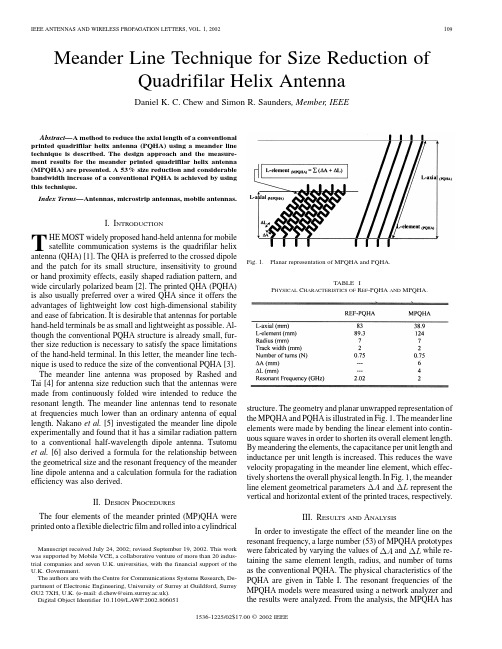
Meander Line Technique for Size Reduction of Quadrifilar Helix AntennaDaniel K.C.Chew and Simon R.Saunders,Member,IEEEAbstract—A method to reduce the axial length of a conventional printed quadrifilar helix antenna(PQHA)using a meander line technique is described.The design approach and the measure-ment results for the meander printed quadrifilar helix antenna (MPQHA)are presented.A53%size reduction and considerable bandwidth increase of a conventional PQHA is achieved by using this technique.Index Terms—Antennas,microstrip antennas,mobile antennas.I.I NTRODUCTIONT HE MOST widely proposed hand-held antenna for mobile satellite communication systems is the quadrifilar helix antenna(QHA)[1].The QHA is preferred to the crossed dipole and the patch for its small structure,insensitivity to ground or hand proximity effects,easily shaped radiation pattern,and wide circularly polarized beam[2].The printed QHA(PQHA) is also usually preferred over a wired QHA since it offers the advantages of lightweight low cost high-dimensional stability and ease of fabrication.It is desirable that antennas for portable hand-held terminals be as small and lightweight as possible.Al-though the conventional PQHA structure is already small,fur-ther size reduction is necessary to satisfy the space limitations of the hand-held terminal.In this letter,the meander line tech-nique is used to reduce the size of the conventional PQHA[3]. The meander line antenna was proposed by Rashed and Tai[4]for antenna size reduction such that the antennas were made from continuously folded wire intended to reduce the resonant length.The meander line antennas tend to resonate at frequencies much lower than an ordinary antenna of equal length.Nakano et al.[5]investigated the meander line dipole experimentally and found that it has a similar radiation pattern to a conventional half-wavelength dipole antenna.Tsutomu et al.[6]also derived a formula for the relationship between the geometrical size and the resonant frequency of the meander line dipole antenna and a calculation formula for the radiation efficiency was also derived.II.D ESIGN P ROCEDURESThe four elements of the meander printed(MP)QHA were printed onto a flexible dielectric film and rolled into a cylindricalManuscript received July24,2002;revised September19,2002.This work was supported by Mobile VCE,a collaborative venture of more than20indus-trial companies and seven U.K.universities,with the financial support of the ernment.The authors are with the Centre for Communications Systems Research,De-partment of Electronic Engineering,University of Surrey at Guildford,Surrey GU27XH,U.K.(e-mail:d.chew@).Digital Object Identifier10.1109/LAWP.2002.806051Fig.1.Planar representation of MPQHA and PQHA.TABLE IP HYSICAL C HARACTERISTICS OF R EF-PQHA ANDMPQHA.structure.The geometry and planar unwrapped representation ofthe MPQHA and PQHA is illustrated in Fig.1.The meander lineelements were made by bending the linear element into contin-uous square waves in order to shorten its overall element length.By meandering the elements,the capacitance per unit length andinductance per unit length is increased.This reduces the wavevelocity propagating in the meander line element,which effec-tively shortens the overall physical length.In Fig.1,the meanderline element geometricalparametersand represent the vertical and horizontal extent of the printed traces,respectively.III.R ESULTS AND A NALYSISIn order to investigate the effect of the meander line on theresonant frequency,a large number(53)of MPQHA prototypeswere fabricated by varying the valuesofand while re-taining the same element length,radius,and number of turnsas the conventional PQHA.The physical characteristics of thePQHA are given in Table I.The resonant frequencies of theMPQHA models were measured using a network analyzer andthe results were analyzed.From the analysis,the MPQHA has 1536-1225/02$17.00©2002IEEEparison of resonant frequency of MDA andMPQHA.Fig.3.S11measurement of the MPQHA compared to the PQHA.similar characteristics to the meander dipole antenna (MDA)in [6].The comparison between the calculated resonant fre-quency of the MDA and the measured resonant frequency of the MPQHA is shown in Fig.2.The deviation between the mea-surements and calculated results for large valuesofis due to the mutual coupling between the opposite elements of the MPQHA,which does not exist in the case of an MDA.From the MPQHA prototypes,the lowest resonant frequency is 2.17GHz.This MPQHA has geometric parametersofmm,mm,and-axial mm.An optimization process was performed on the MPQHA by increasing the element length anddecreasing the valueofwhile retainingthe -axial value at 38.9mm to achieve a resonant frequency of 2GHz.The phys-ical characteristics of the MPQHA that resonates at 2GHz is given in Table I.In Fig.3,the S11of the MPQHA and PQHA are presented.For S11of 10dB,the PQHA has an impedance bandwidth of 90MHz,while the MPQHA has an impedance bandwidth of 190MHz,which is significantly wider.In Figs.4and 5,the radiation pattern for both the PQHA and MPQHA were measured over the frequency range of 1.9–2.2GHz to eval-uate the boresight gain of the two antennas.The PQHA shows a 3-dB bandwidth between 1.9–2.1GHz,while the MPQHA shows a 3-dB bandwidth between 1.9–2.2GHz.The results show that the MPQHA has a wider radiation pattern bandwidth compared to the PQHA although the efficiency was lower.The radiation patterns of the MPQHA and PQHA measured at 2GHzFig.4.Elevation angle radiation pattern measurement of PQHA for frequency range of 1.9–2.2GHz.Fig. 5.Elevation angle radiation pattern measurement of MPQHA for frequency range of 1.9–2.2GHz.Fig.6.Elevation angle radiation pattern measurement of MPQHA and PQHA.are shown in Fig.6.The radiation pattern of the MPQHA dis-plays almost identical characteristics to the radiation pattern of the PQHA.The PQHA has a maximum gainofdBiCat from the zenith.The half-powerbeam width (HPBW)pointoccurs at 76.The MPQHA has a maximum gainof dBiCatCHEW AND SAUNDERS:MEANDER LINE TECHNIQUE FOR SIZE REDUCTION OF QHA111from the zenith.The HPBWpoint occurs at 66.Atelevationangle,the gain difference between the two an-tennas is 1.13dB.At elevationangle ,which is the direc-tion of maximum gain()for the PQHA,the difference in gain between the two antenna is about 2.47dB.IV .C ONCLUSIONThe design approach used to generate the MPQHA has been described.The resonant frequency of the MPQHA is analyzed and compared with the calculated resonant frequency of the MDA.The result shows similar characteristics for small valueof.The measurement results of the MPQHA were presented and compared to that of a conventional PQHA.The meander line technique has been shown useful to reduce the physical length of a conventional ing this technique,the axial length of a conventional PQHA was reduced by 53%with a significantincrease in operating bandwidth at the expense of a slight reduc-tion in efficiency.R EFERENCES[1] C.C.Kilgus,“Shaped-conical radiation pattern performance of thebackfire quadrifilar helix,”IEEE Trans.Antennas Propagat.,vol.23,pp.392–397,May 1975.[2] A.A.Agius,S.M.Leach,and S.R.Saunders,“Antenna design for ICOhandheld terminal,”in Proc.10th Int.Conf.Antennas and Propagation ,Edinburgh,U.K.,Apr.1997.[3]K.C.D.Chew and S.R.Saunders,“Improvements relating to mul-tifilar helix antenna,”U.K.Patent Filing,Application no.0204014.5,Feb.2002.[4]J.Rashed and C.T.Tai,“An new class of resonant antennas,”IEEETrans.Antennas Propagat.,vol.39,pp.1428–1430,Sept.1991.[5]H.Nakano,H.Tagami,A.Yoshizawa,and J.Yanauchi,“Shortening ra-tios of modified dipoles,”IEEE Trans.Antennas Propagat.,vol.AP-32,pp.385–386,Apr.1984.[6] E.Tsutomu,Yonehiko,S.Shinichi,and K.Takashi,“Resonant fre-quency and radiation efficiency of meander line antennas,”mun.Jpn.,vol.83,pp.52–58,2000.。
教你了解GPS的性能关键指标

性能(模块分解),稳定(系统设计),功能;历史负面(行业特点/问题原因办法);追求顾客满意度;目标客户类型(含4S店)教你了解GPS的性能指标发布日期:[2008-7-1] 共阅[1009]次1、卫星轨迹这里有24颗GPS卫星沿六条轨道绕地球运行(每四颗一组),一般不会有超过12个卫星在地球的同一边,大多数GPS接收器可以追踪8~12颗卫星。
计算LAT/LONG(2维)坐标至少需要3颗卫星。
再加一颗就可以计算3维坐标。
对于一个给定的位置,GPS接收器知道在此时哪些卫星在附近,因为它不停地接收从卫星发来的更新信号。
2、并行通道一些消费类GPS设备有2~5条并行通道接收卫星信号。
因为最多可能有12颗卫星是可见的(平均值是8),这意味着GPS接收器必须按顺序访问每一颗卫星来获取每颗卫星的信息。
市面上的GPS接收器大多数是12并行通道型的,这允许它们连续追踪每一颗卫星的信息,12通道接收器的优点包括快速冷启动和初始化卫星的信息,而且在森林地区可以有更好的接收效果。
一般12通道接收器不需要外置天线,除非你是在封闭的空间中,如船舱、车厢中。
3、定位时间这是指你重启动你的GPS接收器时,它确定现在位置所需的时间。
对于12通道接收器,如果你在最后一次定位位置的附近,冷启动时的定位时间一般为3~5分钟,热启动时为15~30秒,而对于2通道接收器,冷启动时大多超过15分钟,热启动时为2~5分钟。
4、定位精度大多数GPS接收器的水平位置定位精度在5m~10m左右,但这只是在SA没有开启的情况下。
5、DGPS功能为了将SA和大气层折射带来的影响降为最低,有一种叫做DGPS发送机的设备。
它是一个固定的GPS接收器(在一个勘探现场100km~200km的半径内设置)接收卫星的信号,它确切地知道理论上卫星信号传送到的精确时间是多少,然后将它与实际传送时间相比较,然后计算出“差”,这十分接近于SA和大气层折射的影响,它将这个差值发送出去,其他GPS接收器就可以利用它得到一个更精确的位置读数(5m~10m或者更少的误差)。
gps宽带四臂螺旋天线研究
摘要摘要自1901年马可尼首次成功实现了无线通信,无线产品相继涌现,已然将人们的生活变得越来越便利。
无线通讯技术发展之迅速、应用之广泛是科技进步的体现也是人们生活品质提高的需求。
在无线通信系统中,天线是一个关键的设备,负责辐射和接收电磁波,其性能参数的优劣直接影响了整个系统的运行。
而天线的种类繁多,不同的应用方向上都有相应的天线来配备使用。
其中四臂螺旋天线不仅具有良好的圆极化性能、心脏形方向图,灵敏度也较高,非常适合作为全球定位系统(Global PositioningSystem,GPS)中的接收天线来使用。
众所周知,全球定位系统随着无线通信技术的发展,早已不局限于军事的应用,慢慢融入了社会发展、经济建设等领域。
越来越广泛的应用,往往意味着越来越高的标准,也就需要越来越深入的研究,尤其是对系统的信号接收起决定性作用的天线。
基于此应用领域,本文结合陶瓷加载、LTCC等技术对宽带化的四臂螺旋天线做了相应的研究和设计工作。
首先是对四臂螺旋天线研究背景的充分介绍和理论基础的详细分析。
四臂螺旋天线的四臂结构形式要获得优良的圆极化特性需等幅正交的馈电,天线设计的工程中不只要考虑天线特性,馈电网络也是一个不可忽视的问题。
另一个值得注意的是天线发展过程中与新材料、新工艺等的结合,这是科技进步的新趋势。
其次介绍了本文设计的一种陶瓷柱加载的四臂螺旋天线。
在天线小型化的道路上,高介电常数陶瓷材料的加载无疑是一重要里程碑,在此基础上,本设计又结合了在天线主辐射臂旁附加短路寄生臂的方法来展宽天线带宽。
经过仿真优化,天线整体尺寸仅为直径10mm、高度12mm的柱体大小,半功率波瓣宽度可达120︒以上,带宽可达15%,且实现了很好的右旋圆极化特性。
之后本文又设计了一种方形印刷四臂螺旋天线。
该天线放弃了传统的柱体绕制结构,采用立方体的相邻四面分别印刷天线四个臂的形式,将四臂螺旋天线的宽波束和良好圆极化特性的优势与微带天线易加工生产的优点相结合。
星载宽波束圆极化天线设计
点。 但是,微带介质材料无法满足星载环境下的抗辐
宽波束天线在工程设计中除了考虑电性能指标的
且降低天线的增益。 双臂螺旋天线结构简单、馈电方
实现外还需要考虑使用的空间环境和加工制造工艺水
便、尺寸较小,但工作带宽较窄,通常需要安装接收和
平。 常用的宽波束天线结构有微带贴片天线
流喇 叭 天 线
[3⁃4]
、四臂螺旋天线
第 40 卷 第 4 期
雷达与对抗
2020 年 12 月
RADAR & ECM
Vol.40 No.4
Dec. 2020
星载宽波束圆极化天线设计
冯文文,李 磊,王群杰,邹永庆
( 中国电子科技集团公司第三十八研究所,合肥 230088)
摘 要:介绍了一种工作在 S 波段的星载宽波束圆极化天线的设计。 该天线采用双臂螺旋天
线结构形式,由螺旋天线、馈电同轴线、裂缝巴伦、复合支撑材料及射频连接器等部分组成。 利
用电磁仿真软件 Ansoft HFSS 对螺旋天线的匝数、螺距和直径进行仿真优化,使其在收发两个
频点下均满足天线增益在±70°波束覆盖范围内大于 1 dB 的指标要求,天线轴比优于 6 dB。 加
工一套天线实物,并在球面近场暗室进行测试。 实测结果显示,天线指标与设计指标相符,为
[5⁃7]
[1⁃2]
、扼
和双臂螺旋天
发射两个天线来实现同时收发的目的。
本文改进了双臂螺旋天线的结构形式。 通过优化
收稿日期:2020⁃10⁃21;修回日期:2020⁃10⁃26
作者简介:冯文文,男,1984 年生,高级工程师,研究方向:微波天馈系统;李磊,男,1972 年生,研究员,研究方向:微波天馈系统;
京:国防工业出版社,2007.
Quadrifilar helix antenna

专利名称:Quadrifilar helix antenna发明人:Steven G. Ow,Peter J. Connolly 申请号:US07/779895申请日:19911021公开号:US05349365A公开日:19940920专利内容由知识产权出版社提供摘要:An improved helix antenna including a single unitary antenna having plural radiating elements extending radially from a common junction. A microstrip balun is connected to the plural antenna elements at the common junction. In a particular embodiment, the antenna includes four radiating elements arranged in a helical pattern and mounted such that a longitudinal axis extending through the axial center of the antenna is coincident with a longitudinal axis of the microstrip balun. One or more of the radiating elements includes a semi-circular loop to create phase relationships necessary for a circularly polarized beam pattern. The microstrip balun includes a transmission line and a ground plane on opposite sides of a dielectric substrate. The transmission line and the ground plane are tapered for impedance matching between the input and the output thereof.申请人:OW; STEVEN G.,CONNOLLY; PETER J.代理机构:Benman, Collins & Sawyer更多信息请下载全文后查看。
一种激光刻蚀制作圆柱形介质天线的方法

一种激光刻蚀制作圆柱形介质天线的方法周洋;王德苗;金浩;郑小婵【摘要】圆柱形介质加载四臂螺旋天线因宽波束、圆极化、体积小等优点被认为是微小卫星天线的理想方案。
为了解决介质加载四臂螺旋天线制作的难点,提出了一种全新的磁控溅射金属化加激光刻蚀的新工艺,采用计算机数控结合激光刻蚀的柔性加工技术,制作出3维立体的四臂螺旋结构,制备了应用于微小卫星系统的介质加载四臂螺旋天线,相对于传统工艺,大大提高了加工精度,并缩短了加工周期。
结果表明,天线的电气性能达到了设计要求,且具有良好的机械性能。
该研究为以后此类曲面共形天线的制作提供了参考。
%Cylindrical dielectric-loaded quadrifilar helix antenna is an ideal choice for small satellite antenna owing to its advantages of wide beam , circular polarization and small volume .In order to solve the difficulty of the manufacture of dielectric-loaded quadrifilar helix antenna , a novel manufacture method combing magnetron sputtering metallization and laser etching wasintroduced .Computer control system with laser etching technology was used to produce three -dimensional quadrifilar helix structure, which is suitable for small satellite systems.The novel process can greatly improve the machining accuracy and shorten the processing cycle compared with traditional process . The results show that the manufactured antenna has good electrical performance , which meets the design requirements of a small satellite system , as well as good mechanical properties .It offers a method of manufacture of the cylindrical conformal antenna .【期刊名称】《激光技术》【年(卷),期】2014(000)003【总页数】4页(P289-292)【关键词】激光技术;介质天线;柔性加工;四臂螺旋;磁控溅射【作者】周洋;王德苗;金浩;郑小婵【作者单位】浙江大学信息与电子工程学系,杭州310027;浙江大学信息与电子工程学系,杭州310027;浙江大学信息与电子工程学系,杭州310027;浙江大学信息与电子工程学系,杭州310027【正文语种】中文【中图分类】TN249四臂螺旋天线最早由KILGUS在1968年提出[1],后因其宽波束、圆极化的特性被广泛应用于空间通讯中[2]。
小型宽波束圆极化天线及馈电网络
小型宽波束圆极化天线及馈电网络丁轲佳;吕善伟;张岩【摘要】提出一种新型的小型宽波束圆极化天线及馈电网络。
天线由四个独立辐射单元顺次旋转90。
组合而成,辐射单元采用平面印刷电路工艺加工、使用容性加载及短路点调配方式实现小型化;使用变形的分支线定向耦合器与移相电路组合,实现具有功率分配与正交移相功能的馈电网络。
经理论分析、软件仿真及实测表明:天线高度小于0.12λ,3dB波束宽度大于120°,6dB轴比波束宽度大于180°,辐射特性在15%相对带宽内稳定;天线的驻波比(VSWR)小于2.0的相对带宽为16%。
该小型宽波束圆极化天线采用印刷电路工艺制作,结构紧凑,加工成本低、精度高,易于与微波电路集成,其结构也适用于S波段以上更高频段。
%A kind of novel compact wide-beam circular polarization antenna and its feed network are presented. The antenna is composed of four independent radiation units which rotate 90° about the center separately. The miniaturization of the anten- na is realized by distributed capacitive load and short point. The feed network is composed of directional coupler and microstrip lines to achieve power division and quartered phase shift. The analysis, simulation and measured results indicate that the antenna's height is less than 0.12λ, the antenna's beam width is greater than 120°,the beam width of axial ratio less than 6dB is greater than 180°,and the char- acters mentioned above can be obtained in the frequency range over 15° band wi dth,the relative band width of VSWR〈2.0 is 16%. The antenna is fabricated by PCB technics and could be integrated to microwave circuit conveniently. The fabri- cation has low cost and highprecision. The structure could also be applied to fre- quency range higher than S band and has broad prospects of application.【期刊名称】《电波科学学报》【年(卷),期】2012(027)004【总页数】6页(P680-684,746)【关键词】宽波束;圆极化;小型化;轴比【作者】丁轲佳;吕善伟;张岩【作者单位】北京航空航天大学,北京100191;北京航空航天大学,北京100191;北京航空航天大学,北京100191【正文语种】中文【中图分类】TN011.4引言伴随卫星通信快速发展,卫星定位与导航、卫星广播通信等技术在军民用领域获得广泛应用。
GPS的平板天线与螺旋天线的比较

GPS的平板天线与螺旋天线的比较GPS接收天线的作用,是将卫星来的无线电信号的电磁波能量变换成接收机电子器件可摄取应用的电流。
天线的大小和形状十分重要,因为这些特征决定了天线能获取微弱的GPS信号的能力。
根据需要,天线可设计成可以工作在单一的L1频率上,也可以工作在L1和L2两个频率上。
由于GPS信号是圆极化波,所以所有的接收天线都是圆极化工作方式。
尽管有多种多样的条件限制,仍然有许多不同的天线类型存在,如单极的,双极的,螺旋的,四臂螺旋的,以及微带天线。
我们在市面上看到的GPS接收器的内置天线一般有两种--平板式天线和四臂螺旋式天线,到底两种天线各有什么优劣呢,让我们来为您一一解答。
平板式天线(Patch Antenna)平板式天线由于其耐用性和相对地容易制作,所以成了应用最为普遍的一类天线。
其形状可以是圆的也可以方的或长方的,如同一块敷铜的印刷电路板。
它由一个或多个金属片构成,所以GPS天线最常用的形状是块状结,像个烧饼。
由于天线可以做得很小,因此适合于航空应用和个人手持应用。
天线的另一个主要特性,是其的增益图形,即方向性。
利用天线的方向性可以提高其抗干和抗多径效应能力。
在精确定位中,天线的相位中心的稳定性是个很重要的指标。
但是,普通的导航应用中,人们希望用全向天线,至少能接收天线地平以上五度视野内所有天空中的可见卫星信号,但是平板式天线在卫星于天线正上方时,讯号增益才是最大,这就有两个问题:1、平板的接收范围在平板上方,平板要面向天空,这对于手持以及车载都会带来麻烦,我们可以看到可调角度的CF接收器越来越多(可折叠的SDGPS丽台9551),就是因为平板式天线这种特性使得厂家为了接收器有更好的收讯效果才想出来的招。
2、我们知道,虽然我们正头顶上的卫星信号比较好,比较容易锁定,但其实正头顶上的卫星是最没用的,如果没有低角度的卫星,误差会相对较高,精度将会很差。
所以基于这些缺点,GPS接收器上也开始使用四臂螺旋式天线。
- 1、下载文档前请自行甄别文档内容的完整性,平台不提供额外的编辑、内容补充、找答案等附加服务。
- 2、"仅部分预览"的文档,不可在线预览部分如存在完整性等问题,可反馈申请退款(可完整预览的文档不适用该条件!)。
- 3、如文档侵犯您的权益,请联系客服反馈,我们会尽快为您处理(人工客服工作时间:9:00-18:30)。
Fu Shi-qiang*, Fang Shao-jun, Lu Kai and Wang Zhong-bao
School of Information Science and Technology, Dalian Maritime University Dalian, Liaoning 116026, China
w h
3mm
D SD/ 4
(a)
(b) Figure 1. (a) The unwrapped antenna and (b) the proposed PQHA
8mm
This work was supported by the National Natural Science Foundation of China (No. 60771032)
III. EXPERIMENTAL RESULTS AND DISCUSSION
The antenna and feed network are simulated with the application of Ansoft HFSS. The simulation results show that the antenna displays good input impedance matching, hemispherical radiation pattern and excellent circular polarization.
___________________________________ 978-1-4244-4076-4/09/$25.00 ©2009 IEEE
Designing the quadrifilar helix is a straightforward procedure; however special care must be taken to ensure that the structure is properly excited for optimum performance. The main complexity of this antenna lies within the feed network design. After selecting the helix parameters that give the desired beam coverage, the mutual input impedance of each winding must be characterized so that an appropriate feeding and matching network can be implemented. In order to make the feed circuit network simplified and miniaturized, the input impedance of this antenna in each port is about 50ȍ without a matching circuit. A new feed network circuit was proposed as can be seen in Fig.1 (b). The feed network designed at 1.59GHz, is placed under the ground plane because of preventing bad effect due to radiation. A branch-line coupler is used to connect to an orthogonal pair of bifilar in quadrature phase. The feeding length between the two ports of one bifilar is about half wavelength so as to provide 180º phase differential without changing the input impedance. The feed network provides an equal distribution of RF signal power to the four helix windings in quadrature phase rotation with 0º, 90º, 180º and 270º phase differentials.
9
8
7
VSWR
6
ห้องสมุดไป่ตู้GPS L1
5
4
receive
transmit
band
band
3
2
1 1.0 1.1 1.2 1.3 1.4 1.5 1.6 1.7 1.8 1.9 2.0 Frequency (GHz)
Practically, the PQHA is composed of four equispaced parallel radiators printed on a thin dielectric substrate wrapped around a cylinder and fed in phase quadrature on each helix. The length of the radiators are normally an odd or even integer multiple of a quarter-wavelength, depending on whether the radiators are open, or short-circuited, respectively. The radiation patterns are typically adjusted by varying the pitch angle of the radiators, the length of the radiators, and the diameter of the core. These radiators require quite complex feed systems [7], and the feeding network requires a fairly large package size and not easy to put into mass production. The purpose of this work is to develop good performance for practical antenna with
Keywords-Printed Quadrifilar Helix Antenna; Circular polarization; BGAN; GPS
I. INTRODUCTION
Satellite mobile communication systems have been widely used these last years such as Inmarsat’s Broadband Global Area Network (BGAN) [1] or Global Positioning System (GPS) [2]. For these applications, circular polarization antennas are well suited for channel transmission due to their insensitivity to ionospheric polarization rotation. A good candidate is the resonant quadrifilar helical antenna (QHA) [3], [4] because it can produce a cardioid shaped radiation pattern with excellent circular polarization. More recently the printed quadrifilar helical antenna (PQHA) [5], [6] has become attractive due to their advantage of light weight, low cost, circular polarization, hemispherical coverage and good axial ratio.
*Email:fushq@
Abstract—A new printed quadrifilar helix antenna with integrated feed network was designed for satellite mobile communication systems. The input impedance of this antenna in each port is about 50ȍ without a matching circuit. It makes the feed network simplified and miniaturized. Parameter tradeoffs have a direct bearing on antenna performance in antenna design. A trial and error approach to this problem is both costly and unreliable. The purpose of this work is to use computer electromagnetic simulation to predict antenna properties for optimum performance. The proposed antenna displays small size, light weight, low cost, large bandwidth, hemispherical radiation pattern and excellent circular polarization.