光照度变送器说明书
仁科光照温湿度变送器(WIFI型)使用说明书

光照温湿度变送器使用说明书(WIFI型)文档版本:V1.0目录1.产品介绍 (4)1.1产品概述 (4)1.2功能特点 (4)1.3主要技术指标 (4)1.4产品选型 (5)1.5设备信息 (5)1.6产品拓扑图 (6)2.设备安装及使用 (7)2.1设备安装说明 (7)2.2设备使用 (8)3.监控平台介绍 (11)4.常见问题及解决办法 (12)5.注意事项 (12)6.联系方式 (13)7.文档历史 (13)8.附录 (14)1.1产品概述RS-GZ-WIFI-2是一款WIFI无线数据传输的工业级通用光照度变送器,该变送器采用高精度感光元件,反应迅速灵敏。
采集数据并通过WIFI方式上传到服务器。
本产品充分利用已架设好的WIFI通讯网络实现数据采集和传输,达到数据集中监控的目的。
可大大减少施工量,提高施工效率和维护成本。
设备10-30V宽压供电,外壳防护等级高,能适应现场各种恶劣条件。
1.2功能特点RS-公司代号GZ/GZWS-光照度变送器WIFI-WIFI型2壁挂王字壳1.5设备信息尺寸产品外观及示意序号名称内容①设备贴膜上面带有产品logo以及名称②NFC感应区域使用NFC配置软件配置时,手机NFC触碰此区域【注意】读取及下发参数时,需等待APP提示成功/失败后,再拿开手机③安装孔位使用配件膨胀螺丝包,将设备安装至墙面等需要安装的位置④精装护套⑤电源线DC5.5*2.1规格;使用配件电源适配器插入供电包装内容主设备×1产品合格证、保修卡×1膨胀螺丝包(含2个自攻螺丝及2个膨胀塞)×112V电源适配器×1USB转485(选配)×11.6产品拓扑图云平台完全免费2.设备安装及使用2.1设备安装说明设备主体的安装2.2设备使用接通电源将电源适配器连接至设备的供电接口,再接通电源连接至网络1下载配置工具,使用QQ扫描二维码(仅限安卓手机),点击“客户端本地下载”,下载完成后根据手机提示将APP安装。
迅捷Fluke IRR1-SOL光照度仪用户手册说明书
Fluke IRR1-SOL Irradiance MeterUsers Manual5237649, September 2020© 2020 Fluke Corporation. All rights reserved.Specifications are subject to change without notice.All product names are trademarks of their respective companies.IntroductionThe Fluke IRR1-SOL Irradiance Meter (the Meter) provides digital read-outs related to photovoltaic (PV) panels. Measures and reads:• Solar irradiation (W/m 2) on the surface of a photovoltaic (PV) panel • Temperature (°F or °C) on the surface of a photovoltaic (PV) panel • Inclination (degrees) of a photovoltaic (PV) panel• Cardinal degrees with the compass functionThe read-outs provided by the Meter help determine optimum positioning of the photovoltaic (PV) panel for best performance. Kit ComponentsThe product contains the following items:1 FLK-IRR1-SOL/001 Solar Irradiance Meter1 FLK-80PR-IRR External Temperature Probe with Suction Cup 1 C250 Carrying Case with Shoulder Strap4 AA Alkaline Batteries1 User ManualSymbolsSafety InformationA Warning identifies hazardous conditions and procedures that are dangerous to the user. A Caution identifies conditions and procedures that can cause damage to the Product or the equipment under test.� WarningTo prevent personal injury and damage to the Product:• Read the entire users manual before using the Meter.• Use the Meter only as described in the Users Manual otherwisethe protection provided by the equipment may be impaired.• Inspect the Meter before use. Do not use it if it appears damaged. • Do not use the Meter around explosive gas, vapor, and/or in damp or wet environments that exceeds IP40.• The Meter contains no user-serviceable parts. Do not openthe instrument.• Use only AA batteries, properly installed in the Meter case, topower the Meter (see Battery Replacement).• To avoid false readings, replace the batteries as soon as the low battery indicator appears.• Remove the batteries if the Meter is not used for an extendedperiod of time, or if stored in temperatures above 140 °F (60 °C).If the batteries are not removed, battery leakage can damage the Meter.• Have the Meter serviced only by qualified service personnel.12OperationChange Temperature UnitsConnect the External Temperature ProbeHold Function346Measuring Inclination and Cardinal Direction Place the Meter directly onto the PV panel to get accurate tilt.The compass measurement will require a two-step process for accurate cardinal direction.Step 1: Perform irradiance, temperature and inclination measurements with meter placed on and aligned with the PV panel. The compass function will show “---” when the tilt angle is above 20 degrees. At a tilt angle of <20 degrees any compass reading shown will be inaccurate due to the influence by surrounding metal objects.Step 2: Perform the compass measurement away from the PV panel by holding the meter or placing meter on a horizontal surface (0 to 20 degrees tilt) pointing the tip of the meter in the direction that the PV panel faces. Keep away from any metal objects.NoteThe compass will reference magnetic north. The compass reading will be unreliable if the meter is placed on or near objects containing metal(including solar panels, metal roofs, concrete surfaces with rebar, etc).7MaintenanceBattery Replacement The battery compartment on the back of the Meter makes it easy to change the batteries. Use four (4) AA 1.5 V alkaline batteries.Note: Batteries are not pre-installed in the meter.1. Make sure that the meter is turned off.2. Use a screw driver to unscrew the captive screw.3. Remove the battery cover.4. Install batteries.5.Replace the battery cover and secure it with the provided screw.Cleaning Periodically wipe the case with a damp cloth and mild detergent.� CautionTo prevent damage to the Meter:• The Meter contains no user-serviceable parts. To avoid injury, or damage to the Meter, do not open the case. • To avoid damaging the Meter, do not use abrasives or solvents to clean the Meter case.Storage During longer periods of non-use (>60 days), remove and store the battery separately.Service and Parts Only a qualified technician should service the Meter. For service information, contact your nearest Fluke dealer or service center.SpecificationsIrradianceMeasuring range ................0 to 1400 W/m²Resolution ..........................1 W/m²Measuring Accuracy ...........±(5 % + 5 Digit)Temperature MeasurementMeasuring range (°C) ......... -30 °C to 100 °C (-22 °F to 212 °F)Resolution .......................... 0.1 °C (0.2 °F / 1 °F @ > 100 °F)Measuring Accuracy ........... ±1 °C (±2 °F) @ -10 °C to 75 °C (14 °F to 167 °F),±2 °C (±4 °F) @ -30 °C to -10 °C (-22 °F to14 °F) and 75 °C to 100 °C (167 °F to 212 °F) Note: Temperature measurement response time: ~30 sec.Inclination AngleMeasuring range ................-90° to +90°Resolution ..........................0.1°Measuring Accuracy ...........±1.5° @ -50° to +50°,±2.5° @ -85° to -50° and +50° to +85°,±3.5° @ -90° to -85° and +85° to +90° CompassMeasuring range ................0° to 360°Resolution ..........................1°Measuring Accuracy (7)Note:a) M easurements valid for device inclination between -20° and +20° tohorizontal. Outside that range on LCD will be shown "---".b) Result is referred to magnetic north.Operating TemperatureOperating temperatures .....I RR1-SOL: -20 °C to 50 °C, humidity <80%,noncondensing80PR-IRR: -30 °C to 100 °CStorage temperature ..........-30 °C to 60 °C (humidity <80%)Altitude ...............................0 m to max. 2000 mElectromagnetic Compatibility (EMC)InternationalIEC 61326-1: Portable Electromagnetic EnvironmentCISPR 11: Group 1, Class AGroup 1: Equipment has intentionally generated and/or uses conductively-coupled radio frequency energy that is necessary for the internal function of the equipment itself.Class A: Equipment is suitable for use in all establishments other than domestic and those directly connected to a low voltage power supply network that supplies buildings used for domestic purposes. There may be potential difficulties in ensuring electromagnetic compatibility in other environments due to conducted and radiated disturbances.Caution: This equipment is not intended for use in residentialenvironments and may not provide adequate protection to radio reception in such environments.Korea (KCC)Class A Equipment (Industrial Broadcasting & Communication Equipment) Class A: Equipment meets requirements for industrial electromagnetic wave equipment and the seller or user should take notice of it. Thisequipment is intended for use in business environments and not to be used in homes.USA (FCC)47 CFR 15 subpart B. This product is considered an exempt device perclause 15.103.ProtectionIP Protection .......................IP40Power Supply & Battery LifeBatteries .............................4 AA Alkaline BatteriesBattery Life (typical) ...........50 hours (>9000 readings)Auto Power Off ..................30 minutesDimensionsL x W x H ............................ 150 x 80 x 35 mm(5.90 x 3.14 x 1.37 in)Weight ................................231g (0.5lb)8。
光照度传感器MODBUS

四、选型:技术说明:1、照度是体现光照强弱的单位,其通俗定义为照到单位面积(m²)上的光通量。
照度单位是每平方米的流明(Lm),也被称为勒克斯(Lux)。
2、1个单位的照度大约为1个烛光在1米距离的光亮度。
在我国,一般情况下,夏日晴天强光下照度为10万Lux(3~30万Lux),阴天照度为1万Lux,日出、日落光照强度为300~400Lux,室内日光灯照度为30~200Lux,夜里0.3~0.03Lux(明亮月光下),0.003~0.0007Lux(阴暗的夜晚)一、产品概述:光照度变送器(光照度传感器)是采用具有较高灵敏度的感光探测器,配合高精度线性放大电路,经过严密检测、生产的具有多种光照测量范围和信号输出类型的实用型产品。
变送器外壳采用壁挂安装设计,结构精致、外型美观,是一款应用范围广泛、性价比极高的光照度测量产品。
五、接线图:三、外形尺寸:RS485(RS232)型接线:供电:红线(V+)黑线(V-)通信:黄线(A+/TXD)蓝线(B-/RXD)电压输出:0-5V 和0-10V 供电:红线(V+)黑线(V-)输出:黄线二线制电流输出接线图V+:红线V-:黑线六、通信说明:(只针对于RS232RS485和无线输出型)典型推荐:室内测量量程0~20000Lux ,室外或温室测量量程:0~20万Lux本产品采用标准Modbus-RTU 通讯协议,产品出厂默认地址为1,波特率为9600,8位数据位,无奇偶校验,1位停止位0~20000Lux光照度上传的数据为真实值0~20万Lux 光照度上传的数据需乘以10才为真实值(采集得到的数据为0~20000)6.1查询地址为1的仪表的光照度值(读输入寄存器)6.2查询地址为1的仪表读保存寄存器6.3写入单个保存寄存器,读从机输入寄存器(4X 类型)中的二进制数据,寄存器所对应的地址分别为0-136.4写入把地址波特率修改为4800(4800的16进制为12C0)七、注意事项:1、使用前请认真阅读说明书、确保接线正确:任何错误接线均有可能对变送器造成不可逆伤害。
光照计使用方法

光照计使用方法
光照计是一种测量光照强度的仪器,常用于光照设计、室内外光照状况分析以及植物生长等应用。
以下是光照计的使用方法:
1. 打开光照计的电源开关。
2. 设置光照计的单位,通常有勒克斯(lux)和法律特(foot-candle)两种选择。
根据需要选择合适的单位。
3. 将光照计的光敏元件(一般是光敏电阻或光敏二极管)暴露在希望测量光照强度的位置,并保持稳定。
4. 读取光照计上的显示数值,即为当前测得的光照强度。
可以在不同位置进行多次测量,以获取更准确的平均值。
5. 如果需要记录测量结果,可以将测量数据记录下来以便后续
分析使用。
6. 使用完毕后,关闭光照计的电源开关,以节省能源并延长电池寿命。
值得注意的是,不同的光照计在使用方法上可能会略有不同,因此在使用前最好查看光照计的说明书,以确保正确操作。
另外,在不同环境下,光照计的测量结果可能会受到其他因素(如摄入角度、反射等)的影响,因此在使用时应尽量保持稳定的测量条件,以获取准确的测量结果。
光照度变送器

光照度变送器用户手册(485型)文档版本:V1.2光照度变送器用户手册 (1)一产品介绍 (2)二设备安装说明 (3)三配置软件安装及使用 (4)四通信协议 (5)五常见问题及解决办法 (7)六联系方式 (7)七文档历史 (7)八附录:壳体尺寸 (7)一产品介绍1、产品概述该变送器广泛适用于适用于室内外环境监测,农业大棚,花卉培养等需要光照度监测的场合。
该传感器采用全隔离,传感器内输入电源,感应线,信号输出三部分完全隔离。
安全可靠,外观美观,安装方便。
2、功能特点本产品采用高灵敏度的感光探头,信号稳定,精度高。
具有测量范围宽、线形度好、防水性能好、使用方便、便于安装、传输距离远等特点。
3、主要技术指标供电电源:9-24V DC光照度测量范围:0-65535lux 光照精度:±5%FS(25℃)存储环境:-40℃~80℃4、系统框架图系统方案框图二设备安装说明2.1设备安装前检查设备清单:●水浸报警器设备1台●12V/2A 防水电源1台(选配)UPS 电源(选配)9~24V DC1号设备2号设备3号设备n 号设备485总线USB 转485或232转485监控电脑市电220VUSB转485(选配)2.2接线宽电压电源输入9~24V均可。
485信号线接线时注意A\B两条线不能接反,总线上多台设备间地址不能冲突。
线色说明电源棕色电源正(9~24V DC)黑色电源负通信黄色485的A端蓝色485的B端三配置软件安装及使用3.1软件安装使用前分别双击,按照提示进行注册,注册完成后,双击,进入设置界面(注:win7电脑请右击此设置工具,以管理员身份注册并运行)。
3.2参数设置1、选择正确的COM口(可在“我的电脑—设备管理器—端口(com和lpt)”里面查看COM端口。
)2、单独接上一台设备并上电,单击软件的测试波特率,软件会测试出当前设备的波特率以及地址,默认波特率为4800bit/s,默认地址为0x01。
光照度测试仪使用方法

光照度测试仪使用方法光照度测试仪是一种测量光源发出光照强度的仪器,是光电工程、光学测量、环境监测等领域中常用的工具之一。
以下是光照度测试仪的使用方法和注意事项的详细描述。
1. 准备工作在使用光照度测试仪之前,需要确保仪器正常工作,并按照说明书中的指示进行操作。
首先,将仪器与光源进行比较,以确保仪器的准确性。
然后,将测试样品放置在仪器上进行测试。
在测试之前,需要将测试样品清洗干净,并确保测试样品表面平整,没有任何凸起或皱折。
2. 测量光源的光照强度将测试样品放置在仪器上进行测试时,需要将仪器的测量范围设置为被测试样品的位置。
然后,将光源放置在测试样品的表面上,并使用仪器上的光源按钮进行测量。
根据仪器上显示的测量结果,可以计算出光源的光照强度。
3. 调整测试样品的位置在测试过程中,可能需要调整测试样品的位置,以确保测试结果的准确性。
例如,如果测试样品表面存在凸起或皱折,需要将其抚平,以确保测试结果的准确性。
4. 记录测试结果在测试过程中,需要记录测试样品的位置和测试时间,并根据仪器上显示的测量结果计算出光源的光照强度。
根据测试结果,可以了解被测试样品的光照强度分布情况、光源的光照强度分布情况等。
5. 分析测试结果在测试完成后,需要对测试结果进行分析,并根据分析结果做出相应的决策。
例如,如果测试结果中发现被测试样品表面存在光照强度不均匀的情况,需要考虑使用光源的均匀性来改善测试结果。
光照度测试仪是一种非常重要的测试工具,可以用于测量光源的光照强度。
在使用光照度测试仪时,需要认真操作,并按照说明书中的指示进行测试和分析。
通过正确使用光照度测试仪,可以更好地了解被测试样品的性能,做出更准确的决策。
光线照度计操作说明书
德信诚培训网
更多免费资料下载请进: 好好学习社区 TES-1334A 光线照度计操作说明书
在您使用本产品前,请详细阅读本说明书,它将教您正确的操作方法及简易的检查处理要领,以便能发挥本表坚固耐用之优良性能。
数字式照度计是一台精密仪器,适合在各种场合测量其照度。
一、数字照度计的特点:
◆TES -1330A -测量范围由 0.01lux~20,000lux (勒克斯)。
◆TES -1332A -测量范围由 0.1lux~200,000lux (勒克斯)。
◆TES -1334A -测量范围由 0.01lux/fc~20,000lux/fc (勒克斯 /呎烛光)。
◆准确度高以及反映速度快。
◆TES -1334峰值锁定功能,能追踪大于50.0ms 的脉冲信号,锁定其峰值。
◆读值锁定功能,可锁定测定值。
◆符号及单位显示,读取方便。
◆自动归零。
二、数字照度计的规格:
◆显 示:31/2位液晶显示器显示,最大读值1999。
◆测量范围:
◇TES -1330-20,200,2,000,20,000lux(20,000lux 文件显示之读值需×10才为正确照度值) ◇TES -1332-200,2,000,20,000,200,000lux(20,000lux 文件显示之读值需×10,及200,000lux 文件显示之读值需×100才为正确照度值)
◇TES -1334-20,200,2,000,20,000lux/fc(20,000lux/fc 文件显示之读值需×100才为正确照度值)
◇注:1fc =10.76Lux。
光照度测量仪 LumiTop 2700 4000 产品说明书

LumiTop 2700/4000 Spectrally enhanced imaging colorimeter\\ L ab specs meet production speedThe LumiTop 2700/4000 combines the accuracy of Instrument Systems’ well-known spectroradiometers of the CAS series with the obvious advantages of imaging colorimetry. Principle: Fast and accurate With the help of a polarization insensitive, three-way beam splitter, the LumiTop 2700/4000 mergesan RGB CCD/CMOS camera anda flicker diode with the high-end spectroradiometer of the CAS series. This innovative design allows for simultaneous measurements of all components, which may result in significant time-savings.At the same time, the extremely accurate spectral information of the spectroradiometer measurement is used as reference for the camera measurement. This guarantees spectroradiometric accuracy across the whole 2D image.As a result, the LumiTop 2700/4000 not only performs fast 2D measurements with unprecedented accuracy but also offers all the advantages of classical imaging colorimetry. Perfect for productionBecause of this combination, theLumiTop 2700/4000 is perfectfor use in display productionlines or quality control, where thebenefits and capabilities of both,the accurate spot measurement ofspectroradiometers and the lateralresolution of camera measurementsare highly valued.All-in-one solutionMany different test applications cannow be organized in a single teststation:y M easurement of luminance andcolory E valuation of color and luminanceuniformity or Mura effectsy P ixel metrology including pixeldefect analysisy C ontrast measurementy A nalysis of white balance or colorgamuty F licker and luminance modulationmeasurementy A nalysis of the acquired spectraEasy to integrate intoproduction linesThe LumiTop 2700/4000 isintegrated in Instrument Systems’comprehensive new software“LumiSuite”, which comes witha user-friendly GUI for laboratoryapplications and a powerfulsoftware development kit for easyimplementation into any productionline. The spectra measured asreference for the camera can beanalyzed in more detail usingInstrument Systems’ well-knownsoftware SpecWin Pro.Independent of displaytechnologyDue to the high absolute accuracyof the CAS spectroradiometer thatis used as reference during eachmeasurement, the performanceof the solution is excellent for anydisplay technology (or any otherhomogeneous samples). Moreoverno golden sample or user calibrationsare needed. This makes the solutionparticularly favorable when OLEDs orother narrow-banded light sourceshave to be investigated where classicalimaging colorimeters based on XYZfilter technologies reach their limits.ModularityThe LumiTop 2700/4000 is designedas a modular accessory to any of thespectroradiometers of the CAS series.Thus the same spectroradiometerscan also be used with the telescopicoptics TOP 150 or TOP 200.\\Technical specifications1)Inclusive lens and fiber exit.2)Without CAS, with mode mixer.3)E xternal neutral density filters on the lens (OD 0.3/0.6/0.9) are available for increasingthe upper measurement limit or measuring modulated light sources.4)L ower measurement limit based on a signal to noise ratio of 10:1 for maximumexposure time (60 seconds LumiTop 2700 / 10 seconds LumiTop 4000). Uppermeasurement limit based on a signal level < 80 % for a white (non-modulated) LED light source using for minimum exposure time (1 ms LumiTop 2700 / 27 µs LumiTop 4000).5)T ypical value for maximum deviation over the FOV relative to the CAS spot;calculated for an image with 16 pixels (LumiTop 2700) / 21 pixels (LumiTop 4000) cropped at each edge and 10 by 10 pixels (LumiTop 2700) / 13 by 13 pixels(LumiTop 4000) binning (34 averages) immediately after calibration with reference used for flat-field correction.6)2σ of repeated measurements of one instrument (L ≈ 100 cd/m2, autoexposure).7)R NU (response non-uniformity) is defined as 99.7 % percentile of the deviationof the mean image value; calculated for an image with 16 pixels (LumiTop 2700) /21 pixels (LumiTop 4000) cropped at each edge and 10 by 10 pixels (LumiTop 2700) /13 by 13 pixels (LumiTop 4000) binning (34 averages) immediately after calibrationwith reference used for flat-field correction.8)T ime between beginning of two subsequent measurements using the SDK;determined with a camera exposure time of 20 ms and CAS exposure time of200 ms for a white LED (L ≈ 500 cd/m2). Depends mainly on PC processing capability.9)L ower measurement limit based on a signal to noise ratio of 10:1 for maximumexposure times 65 s for CAS 140D and CAS 140CT, 20 s for CAS 120. Uppermeasurement limit based on a signal level < 80 % for a white (non-modulated) LED light source using a CAS internal optical density filter OD4 and minimum exposure time (10 ms CAS 140CT / 4 ms CAS 140D and CAS 120). Values valid for CAS 140CT, CAS 120 with 100 μm and CAS 140D with 250 μm slit width.10)I mmediately after calibration relative to calibration standard.11)I mmediately after calibration.12)M aximum deviation from average of repeated CAS measurements with a linearpolarized light source and varying polarization angle.13)L ≈ 150 cd/m2, 30 Hz, 10 % sine wave.14) 2σ of repeated measurements of one instrument.15)Distance between DUT and front plate of LumiTop.We bring quality to light.Instrument Systems GmbH Kastenbauerstr. 281677 Munich, Germany ph: +49 (0)89 45 49 43-58 fax: +49 (0)89 45 49 43-11 **************************b _L u m i T o p _e n _V 1.7Instrument Systems is continually working on the further development of its products. Technical changes, errors and misprints do not justify claims for damages. For all other purposes, our Terms and Conditions of Business shall be applicable.。
光照度传感器 LH-LR2000 说明书

光照度传感器说明书适用型号:LH-LR2000修订记录:目录1.产品介绍 (2)2.规格参数 (2)3.产品尺寸 (3)4.485通信协议与数据格式 (3)4.1.通讯基本参数 (3)4.2.数据帧格式定义 (3)4.3.寄存器地址 (4)4.4.参数读取 (5)5.模拟量协议 (6)6.电气接线 (6)7.售后服务 (7)7.1.售后服务承诺 (7)7.2.免责声明 (8)7.3.联系方式 (8)1.产品介绍该变送器广泛适用于农业大棚、花卉培养等需要光照度监测的场合。
传感器内部的输入电源、感应探头、信号输出三部分完全隔离。
安全可靠,外观美观,安装方便。
2.规格参数3.产品尺寸图3.14.485通信协议与数据格式4.1.通讯基本参数4.2.数据帧格式定义采用Modbus-RTU 通询规约,格式如下:地址码=1字节功能码=1字节数据区=N字节错误校验=16位CRC码结束结构>=4字节的时间地址码:为设备的地址,在通询网络中是唯一的。
功能码:主机所发指令功能提示。
数据区:数据区是具体通询数区,注意16bits数据高字节在前。
CRC码:二字节的校验码。
地址码功能码寄存器起始地址寄存器长度校验码低位校验码高位问询1字节1字节2字节2字节1字节1字节地址码功能码有效字节数数据区校验码低位校验码高位应答1字节1字节1字节2字节1字节1字节4.3.寄存器地址4.4.参数读取(1)例:读取设备地址为01的传感器光照度地址码功能码起始地址数据值校验码低位校验码高位问询0x010x030x00,0x070x00,0x020x750xCA地址码功能码字节数数据值校验码低位校验码高位应答0x010x030x040x000x00,0x060xF60x7A0x31注释:光照度计算说明:000006F6H(十六进制)=1782=>光照度=1782Lux(2)例:查询设备地址、波特率地址码功能码起始地址数据值CRC低位CRC高位问询0x010x030x01,0x000x00,0x020xC50xF7应答地址码功能码有效字节数设备地址波特率CRC 低位CRC 高位0x010x030x040x00,0x010x00,0x030xEB0xF2读出设备地址为1;波特率为9600。
光照度变送器产品使用手册说明书
1光照度变送器产品使用手册1概述LT-CG-S/D-001-A0220-12光照度传感器探头选用国外进口感光芯片,菲尼尔透镜聚光,标准0~65535LUX 测量量程,完全满足室内光照度测量。
产品测量精度高,线性度好。
作为现场采集从站,按照标准MODBUS-RTU 通信协议RS485数字信号输出,适合远距离组网传输。
可选配液晶屏现场显示测量数据,还可选配1路继电器报警输出。
完全兼容组态王等多种上位机组态软件,易与第三方设备配套。
可广泛用于农业大棚、智能养殖、智能家居及工厂商厦等环境监测领域。
2外形规格3产品技术指标规格型号:LT-CG-S/T-005-A0121-12-V1.1(包含液晶屏)LT-CG-S/T-005-A0120-12-V1.1(不含液晶屏)LT-CG-S/T-005-A0121-DO-12-V1.1(包含液晶屏、1路报警)可见光检测波段:可见光,波长400~730nm,波峰560nm光照度测量范围:0~70KLUX光照度测量精度:±7%光照度分辨率:1LUX光照度测量重复性:±5%测量稳定时间:0.5秒响应时间:<1秒2工作环境:-20~55度,5~95%RH存储环境:-25~60度供电电压:DC7~24V显示方式:LCD液晶屏(选项)液晶屏规格:08022行显示,每行8个字符变送器可选配1路报警输出,继电器控制报警设备动作通信接口:RS485通信速率:2400、4800、9600、19200、38400、115200。
默认9600bps.通信协议:MODBUS-RTU数据格式:1、8、1、9600(1位起始位、8位数据位、1位停止位、无校验、9600bps波特率)通信方式:作为MODBUS从站,采用主从轮询方式相应主站请求,将数据上传。
终端类别:从站节点地址:001~255,由拨码开关硬件设定节点数量:31传输距离:500米(RS485通信专用电缆)变送器出厂前经过三防处理,确保高温高湿特殊环境下长期使用。
485 型光照度变送器使用说明书

485型光照度变送器使用说明书Ver1.1第1章产品简介1.1产品概述该变送器广泛适用于农业大棚、花卉培养等需要光照度监测的场合。
传感器内输入电源,感应探头,信号输出三部分完全隔离。
安全可靠,外观美观,安装方便。
1.2功能特点本产品采用高灵敏度的感光探头,信号稳定,精度高。
具有测量范围宽、线形度好、防水性能好、使用方便、便于安装、传输距离远等特点。
1.3主要参数1.3.1基本参数参数名称参数内容直流供电(默认)12-24V DC耗电≤0.15W(@12V DC , 25℃)光照强度精度±5%(25℃)光照强度0-65535Lux/0-20万Lux长期稳定性(光照强度)≤5%/y1.3.2光照参数图1.不同波长光线对光照度影响如图1所示,波长在580nm左右最准确,比例系数为1.图2.光照角度影响示意图如图2所示角度对光照准确度影响较大,用户使用时应注意角度的变化,以正上方为照射基准。
图3.不同温度影响示意图如上图所示温度对光照模块影响较小,温度在20摄氏度左右准确度最高,随温度的逐渐升高(下降),呈线性变化。
1.4探头参数与选型型号量程适用范围分辨率20W 200000Lux 室外日光强测量1Lux6W 65535Lux 室内光强度测量1Lux 为了方便用户选择正确的量程,特给出一些常见环境的光照度:夏季在阳光直接照射下,光照强度可达6万~10万lux,没有太阳的室外0.1万~1万lux,夏天明朗的室内100~550lux,夜间满月下为0.2lux。
1.5系统框架图本传感器可以连接单独使用,首先使用12V直流电源供电,设备可以直接连接带有485接口的PLC,可以通过485接口芯片连接单片机。
通过后文指定的modbus协议对单片机和PLC进行编程即可配合传感器使用。
同时使用USB转485即可与电脑连接,使用我公司提供的传感器配置工具进行配置和测试。
本产品也可以多个传感器组合在一条485总线使用,在进行485总线组合时请遵守“485总线现场接线守则”(见附录)。
GOSSEN MAVOLUX 5032 C B USB 光照度计说明书

Luxmeters / Footcandle Meters MAVOLUX 5032 C/B USBIlluminance meters of the precision class C or BFeatures• Precision meters for measuring the illuminance inLux and Footcandles meeting StandardSpecification DIN 5032-7, Class C or B andEN 13032-1, Appendix B• The silicon photo diode is colour corrected, i.e. itsspectral responsitivity is matched to the photopicdaylight vision of the human eye V(λ).• Luminance can be measured in cd/m² or fL whenusing the Luminance Attachment (optional accessory)• Cosine correction for light inciding at an angle• Easy to use• 3 ½ digits display• Backlight display illumination (only inMAVOLUX 5032 B USB)• Data storage of up to 100 measurements• Auto and manual range selection• USB Port 1.1• CD-Rom with software for processing the valuesmeasured and controlling the meter• Compact transport case and USB cable includedT he GOSSEN digital precision luxmeters are classified according to DIN 5032-7 in Class C or B and EN 13032-1, Appendix B. Wide range of applications: for lighting engineers and specifiers, for the control of light sources, street lights, lighting of work places, public buildings, sport facilities, for quality control and quality assurance in the manufacture of lamps and light sources, for light designers and architects, for light measurements in agriculture, gardening and forestry.B oth MAVOLUX types are optimally suited for measuring very high light intensities (brightestdaylight, head lights) without any additional accessories. Especially the MAVOLUX 5032 B USB having an initial sensitivity of 0.01 lx also allows measuring extremely low light intensities, such as emergency lighting. Most important: Due to its high precision acc. to Class B, the MAVOLUX 5032 B USB has been approved for certification and official inspection procedures. W hen attaching the Luminance Attachment to the measuring probe of the MAVOLUX 5032C or B USB, they can be used also for measuring the luminance; the measuring angle being approx. 20°. Luminance is the reflected light effect of self luminous or reflecting surfaces. The measuring unit is candela per square meter (cd/m²) or foot Lambert (fL).Calibration CertificateWhen required, to be specificly ordered together with the lightmeter. Please see page 12 of this brochure for more information.2Gossen Foto- und Lichtmesstechnik GmbHLuxmeters / Footcandle MetersMAVOLUX 5032 C/B USBModel MAVOLUX 5032 C USBMAVOLUX 5032 B USBType Illuminance meter for measuring lightAccuracy Class C acc. DIN 5032-7Class B acc. DIN 5032-7LCD Display 3 1/2 digits3 1/2 digits,with backlight display illuminationLight sensor Silicon photo diode with V (λ) filteringMeasuring unitLux or footcandle (fc) and with Luminance Attachment cd/m² orfoot Lambert (fL)Measuring ranges Automatic and manual measuring range selection0.1 lx to 199 900 lx and1 cd/m² to 1 999 000 cd/m² in 4 ranges (with Luminance Attachment)0.01 lx to 199 900 lx and0.1 cd/m² to 1 999 000 cd/m² in 5 ranges (with Luminance Attachment)Data memory 100 individual measuring values Measuring rate 2 measurements per secondUSB Port USB 1.1Operating temperature 0° C to 50° CAccording EN 61010-1:2001, cl. 1.4.1Storagetemperature -20°C to +70° CPower supply 1 x 1,5 V, size AA , when meter is connected to PC,power will be supplied via USB cableSoftwaregLux Software and additional applicationsConnection cable 1.5 m cable, firmly attached1.5 m cable (plugged in)Weight 200 g without batteryStandard Accessories Lightmeter in transport case, gLux Software incl. meter driver,USB cable, battery, instruction manualOptional AccessoriesLuminance Attachment (measuring angle 20°)Adapter disk for luminance contact measurement (eliminating lightincident from the sides)Specifications:Applications - Examples:Measuring the emergency lighting in emergency exitsTV StudiosSports Arenas 3Gossen Foto- und Lichtmesstechnik GmbHMAVOLUX 5032 C/B USBDescriptionOrdering code MAVOLUX 5032 C USBincl. transport case, software, USB cable, battery, instruction manual M502G MAVOLUX 5032 B USBincl. transport case, software, USB cable, battery, instruction manual M503G Calibration Certificate for Mavolux 5032 C/B USB * (please see page 12)H997BAccessories for MAVOLUX 5032 C /B USBLuminance Attachment for measuring in cd/m² and fL5908V0120Adapter disk for contact measurement (for use only with the Luminance Attachment)M499G Special length cables for MAVOLUX 5032 C or B USB 3 meters for MAVOLUX 5032 C USB *151435 meters for MAVOLUX 5032 C USB *1514410 meters for MAVOLUX 5032 C USB *151453 meters for MAVOLUX 5032 B USB *151465 meters for MAVOLUX 5032 B USB *1514710 meters for MAVOLUX 5032 B USB *15148* The extra length cables and the Calibration Certificates must be ordered already together with the meters.Ordering information:The MAVOLUX 5032 C/B USB is supplied in a practical and compact transport case.Measuring probe with Luminance Attachment mounted and Adapter disk4Gossen Foto- und Lichtmesstechnik GmbHOptional accessories:Luminance Attach- ment, Adapter disk for eliminating light inciding from the sides, with contact measurement.Luxmeters / Footcandle Meters。
LT40 白色 LED 光照度计 用户手册说明书
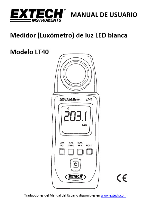
MANUAL DE USUARIOMedidor (Luxómetro) de luz LED blancaModelo LT40Traducciones del Manual del Usuario disponibles en IntroducciónAgradecemos su compra del Luxómetro LED LT40 de Extech para medir la intensidad de la luz de fuentes LED blanca. El LT40 también puede medir luz de fuentes fluorescentes, halogenuros metálicos, sodio de alta presión e incandescentes. El LT40 puede medir la luz hasta 40,000 Fc (400,000 Lux). Este instrumento se embarca probado y calibrado y con uso apropiado le proveerá muchos años de servicio confiable. Por favor Visite nuestra página en Internet () para descargar la versión más reciente de esta Guía del Usuario, actualizaciones de producto y Soporte al Cliente.Características∙Indicación de sobre carga: La LCD indica "OL".∙Indicación de batería débil.∙Frecuencia de actualización de pantalla: 2.5 veces por segundo.∙Ángulo Coseno corregido.∙Mide LED de luz blanca.∙Mide la intensidad de iluminación en Lux o bujías‐pie.∙Retención de datos inmoviliza la lectura presentada.∙Retención de lectura máxima / promedio / mínima∙Ajuste de calibración a cero.∙Apagado automático desactivable.∙Escala automática.Seguridad∙No utilice el medidor en ambientes en los que los siguientes estén presentes: gases explosivos (o materiales), gases combustibles (o materiales), vapor o polvo.∙No toque por ningún motivo la tarjeta de circuitos del medidor ya que la electricidad estática o la contaminación pueden dañar los componentes sensibles.∙Solamente para uso en interiores. Este instrumento ha sido diseñado para el grado de contaminación 2.∙Altitud de funcionamiento: Hasta 2000m (7000’).Descripción del medidor1.Foto detector (quite la cubierta protectora para2.Pantalla (LCD)3.Botones de control4.Botón de encendido: ON/OFFEl compartimiento de la batería y base para trípode se encuentran atrás del instrumentoDescripción de botones pulsador1.Selector de unidades Lux / Fc2.Botón de calibración CERO3.Botón de memoria máxima / promedio / mínima4.Botón para retención (HOLD) de datosOperaciónBotón de encendido y apagado (ON/OFF)Presione largo el botón de encendido para encender el medidor. Para apagar el medidor, presione momentáneamente el botón de encendido.Toma de mediciones1.Encienda el medidor y retire la cubierta protectora del sensor para exponer el domo sensorde luz. La pantalla debe encender, si no, compruebe que las baterías estén instaladas ycargadas.2.El medidor mide la intensidad de la luz (iluminación) que impacta la cúpula del sensor enbujías pie y unidades lux (1 fc = 10.76 lux), que muestra el valor medido en la pantalla LCD.3.Coloque el medidor y la fuente de luz de manera que la luz impacte directamente la cúpuladel sensor (perpendicular) con el menor ángulo posible. pantalla del medidor puede mostrar un valor de hasta 9999. Sin embargo, para laslecturas que representan mediciones superiores a esto, el medidor utiliza la función x10 o x1000. Por ejemplo, para representar una medida de 11,000 fc el medidor indicará 1100 con el indicador x10.Apagado automáticoPara ahorrar batería, el medidor se apagará automáticamente después de aproximadamente 12 minutos de inactividad.Activar / desactivar apagado automáticoMientras el medidor está encendido, presione largo el botón de encendido para desactivar la función de apagado automático; el símbolo del reloj se apagará. Para activar la función de apagado automático, repita este proceso.Botón LUX / FCPresione el botón LUX / FC para alternar entre unidades de medida Lux y FC (Bujías‐pie).Botón MÁX/MINEl medidor puede registrar la lectura máxima, mínima y promedio como se describe a continuación:1.Presione momentáneamente el botón "MAX / MIN" y el medidor empezará a rastrear lasmedidas máximas / promedio / mínima; el icono "MAX" aparecerá en la parte superior de la pantalla LCD indicando que el medidor está mostrando la lectura máxima. La lectura nocambiará hasta que se haya registrado una lectura más alta.2.Presione el botón "MAX / MIN" otra vez para cambiar de "MAX" a "AVG", donde el medidormostrará el valor promedio de las mediciones. El icono "AVG" aparecerá por encima delvalor mostrado.3.Presione el botón "MAX / MIN" otra vez para cambiar el modo de "AVG" a "MIN", donde elmedidor mostrará el valor mínimo medido. Se mostrará el icono "MIN".4.Presione el botón "MAX / MIN" otra vez para cambiar de "MIN" a "MAX”.5.Para salir de este modo, mantenga presionado el botón "MAX / MIN" durante al menos 2segundos. Los iconos MAX / AVG / MIN se deben apagar todos cuando la unidad vuelve al modo de funcionamiento normal.Botón 'Hold' para retención de datosPresione el botón HOLD para inmovilizar la lectura actual en la pantalla LCD. Presione el botón HOLD de nuevo para soltar la lectura. En modo retención, la LCD muestra HOLD. Procedimiento de calibración cero1.Asegúrese de que la cubierta de protección está sujetada al sensor de luz.2.Encienda el medidor y la pantalla LCD debe mostrar '0’.3.Presione corto el botón "CAL ZERO" para ejecutar el ajuste a cero (CAL aparece en la pantalla).4.CAL se apagará al terminar la calibración.5.Si la tapa protectora no está cubriendo el sensor al iniciar la calibración CERO, la pantalla LCDindicará "CAP”. En este caso, por favor, cubra el sensor con la tapa y repita este procedimiento.Consideraciones de medición y sugerencias para los usuarios∙ Para mayor precisión permita que la luz a medir entre directamente en el sensor lo más perpendicular posible con un ángulo mínimo de incidencia.∙ Cuando el medidor no esté en uso, por favor mantenga la tapa protectora en su lugar sobre el sensor de luz. Esto prolongará la vida útil del sensor.∙Cuando se va a almacenar el medidor durante mucho tiempo, por favor, quite las pilas y guardarlas por separado. Las baterías pueden tener derrames y causar daños a los componentes del medidor.∙Evite las áreas de alta temperatura y humedad al utilizar este instrumento.Reemplazo de la batería y MantenimientoLimpieza y almacenamiento1. El domo de plástico blanco del sensor deberá limpiarse con un paño húmedo cuando seanecesario. Use sólo un jabón suave si es necesario. No use solventes, abrasivos o detergentes fuertes para limpiar el domo.2. Guarde el medidor en un área con temperatura y humedadrelativa moderadas.Reemplazo de la bateríaCuando la energía de la batería cae a un nivel crítico, en la LCD aparece el símbolo de batería baja “ Reemplace las 2 pilas AAA de 1.5 V en el compartimiento de baterías.1. Para quitar la tapa del compartimiento de las baterías (verdiagrama) presione la traba de la tapa 2. Deslice la tapa en la dirección de la flecha.Instale dos (2) baterías ‘AAA’ de 1.5V observando la polaridad correcta y coloque y asegure la tapa con la traba antes de usar el medidor.Nunca deseche las baterías usadas o baterías recargables en la basura de la casa . Como consumidores, los usuarios están obligados por ley a llevar las pilas usadas a los sitios adecuados de recolección, la tienda minorista donde se compraron las baterías, o dondequiera que se venden baterías.Disposición: No deseche este instrumento en la basura de la casa. Elusuario está obligado a llevar los dispositivos al final de su vida útil a un punto de recolección designado para el desecho de equipos eléctricos y electrónicos.Recordatorios de seguridad de bateríaso Deshágase de las baterías de manera responsable, respete las normas locales, estatales y nacionales. o Nunca arroje las baterías al fuego; las baterías pueden explotar o derramarse. oNunca mezcle tipos de pilas diferentes, instale pilas nuevas del mismo tipo.Fuente de luz a 0 gradosEspecificacionesUnidades Rango Resolución PrecisiónLux999.9 0.1LED blanco:± (3% lectura + 3 Lux) hasta 500 Lux± (3% lectura) >500 LuxOtras fuentes de luz visible: No especificado 9,999 199,990* 10400,000* 100Bujías pie99.99 0.01LED blanco:± (3% lectura + 0.3 Fc) hasta 46 Fc± (3% lectura) >46 FcOtras fuentes de luz visible: No especificado 999.9 0.19,999 140,000* 10* Las lecturas mayores a 9999 usan un multiplicador x10 o x100 (1 Fc = 10.76 Lux)Ángulo de desviación de las características decoseno 30° ±2% 60° ±6% 80° ±25%Especificaciones generalesFrecuencia de muestreo 2.5 veces por segundo (pantalla digital)Foto detector Foto diodo de silicio con corrección del cosenoPantalla LCD de 4 dígitos (visualización máxima: 9999) con icono debatería baja, sobrecarga, medición y otros indicadores defunciónEscala automática Ajuste automático de la escala de la pantalla Condiciones de operación Temperatura: 5 a 40o C (41 a 104o F); Humedad: < 80% HR Condiciones de almacenamiento Temperatura: ‐10 a 60o C (14 a 140o F); Humedad: < 70 %RH Indicador de batería débil “ en LCD cuando el voltaje de la batería esdemasiado bajoTipo de LED La luz LED blancaFuente de alimentación 2 baterías “AAA" de x 1.5VVida de la batería Aproximadamente 200 horasApagado automático El medidor se apaga después de 12 minutos de inactividad Dimensiones 133 x 48 x 23mm (5.2 x 1.9 x 0.9”)Peso 250g. (8.8 oz) Incluidas las bateríasApéndicesNiveles típicos de luz (1 Fc = 10.76 Lux)Lux Bujías pie Lux Bujías pieFábricas Hogar 20‐75 2‐7 Escaleras de emergencia,Almacén100‐150 10‐15 Lavandería75‐150 7‐15 Pasillos de Entrada/Salida 150‐200 15‐20 Actividadesrecreativas 150‐300 15‐30 Trabajo de embalaje 200‐300 20‐30 Estudio, Mesa 300‐750 30‐75 Trabajo visual Línea deproducción300‐500 30‐50 Maquillaje750‐1,500 75‐150 Tipografía: Trabajo de inspección500‐1,500 50‐150 Lectura, Estudio 1,500‐3,000 150‐300 Montaje electrónico , Dibujo 1,000‐2,000 100‐200 Costura Oficinas Restaurante 75‐100 7‐10 Escaleras internas de emergencia75‐150 7‐15 Pasillo de escaleras 100‐200 10‐20 Pasillo de escaleras 150‐300 15‐30 Entrada,Lavabo200‐750 20‐75 Conferencia,Recepción 300‐750 30‐75 Cocina, mesa decomedor750‐1,500 75‐150 Trabajo de oficina 750‐1,500 75‐150 Aparador1,500‐2,000 150‐2000 Mecanografía, dibujo Tienda Hospital 75‐150 7‐15 Interior 30‐75 3‐7 Escaleras deemergencia 150‐200 15‐20 Pasillo/Escaleras 75‐100 7‐10 Escaleras200‐300 20‐30 Recepción 100‐150 10‐15 Enfermería,Almacén 300‐500 30‐50 Estante para exhibición 150‐200 15‐20 Cuarto de espera 500‐750 50‐75 Elevador 200‐750 20‐75 Cuarto de examenmédico750‐1,500 75‐150 Aparador,Mesa para empaque750‐1,500 75‐150 Quirófano1,500‐3,000 150‐300 Fachada, Aparador 5,000‐10,000500‐1000 Inspección ocularCopyright © 2013‐2017 FLIR Systems, Inc.All rights reserved including the right of reproduction in whole or in part in any formISO‐9001 Certified。
MA-T6 MA-T12 分光光度仪 用户指南说明书
MA-T6/MA-T12分光光度仪用户指南凡出现“注意”符号时,请参阅本文档。
此符号用于提醒可能需要注意的任何潜在危险或操作。
CE 声明爱色丽有限公司特此宣布,符合 R & TTE 1999/5/EC、LVD 2014/35/EU 和 RoHS 2011/65/EU 等指令的基本要求及其他相关规定。
EAC 认证爱色丽有限公司特此宣布,此设备符合按照以下申报登记号的关税同盟其技术法规:ТС N RU Д-US.А301.В.01051有关更多信息,请访问.ru/美国联邦通讯委员会通知注意:本设备经测试,证明符合依据 FCC 规则第 15 部分对 A 类数字设备的限制。
这些限制旨在对商业环境下运行的设备提供合理保护,免受有害干扰。
本设备生成、使用并可能放射射频能量;因此,如未按照操作手册安装和使用,可能会对无线电通信产生有害干扰。
在住宅区操作本设备可能产生有害干扰,此时将要求用户自付费用来纠正干扰。
注意:未经(制造商名称)明确批准即对本设备所做的更改或修改可能导致 FCC 对操作本设备的授权失效。
加拿大工业符合性声明CAN ICES-3 (A) / NMB-3 (A)无线电射频暴露•设备的辐射输出功率远低于 FCC 的无线电射频暴露限制。
尽管如此,应以将 Wi-Fi 传输过程中人体接触可能性降到最低限度的方式使用设备。
•La puissance rayonnée par cet appareil est très inférieure aux limites d'exposition aux ondes radio définies par la FCC.Néanmoins, l’appareil doit être utilisé de telle manière que lepotentiel de contact humain pendant la transmission par Wi-Fi soit minimisé.设备信息以不同于爱色丽有限公司指定方式使用本设备可能会损坏其设计完整性并导致不安全。
SM5361B户外型光照度传感器产品使用手册说明书
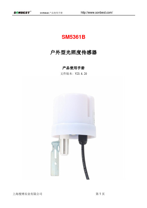
SM5361B户外型光照度传感器产品使用手册文件版本: V23.6.20SM5361B采用工业通用标准RS485总线 MODBUS-RTU协议接口,方便接入PLC,DCS等各种仪表或系统,用于监测光照度等状态量。
内部使用了较高精度的传感内核及相关器件,确保产品具有较高的可靠性与卓越的长期稳定性, 可定制RS232、RS485、CAN、4-20mA、DC0~5V\10V、ZIGBEE、Lora、WIFI、GPRS、NB-IOT等多种输出方式。
技术参数产品接线请在断电线的情况下,按图示方法进行接线,如果产品本身无引线,线芯颜色供参考。
典型应用应用方案发货清单RS485型:通讯协议产品使用RS485 MODBUS-RTU标准协议格式,所有操作或回复命令都为16进制数据。
设备出厂时默认设备地址为1,默认波特率为模块及非记录仪表:9600,8,n,1 或记录仪:115200,8,n,1 。
1. 读取数据( 功能码0x03)问询帧(十六进制),发送举例:查询1#设备1个数据,上位机发送命令:01 03 00 00 00的产品,温度、湿度数据倍率为100,光照数据倍率为1或10。
本产品的数据倍率为10,则真实值为:121*10=1210,其它以此类推。
对于光照度,由于每个参数占2个字节且20万量程的光照度实际分辨率低于10,所以我们以20000即2万来表达20万,即倍率为10。
比如当读到的数据为839时,实际光照度值为8390LUX。
2. 常用数据地址表3 读取与修改设备地址(1)读取或查询设备地址若不知道当前设备地址、且总线上只有一个设备时,可以通过命令FA 03 00 66 00 01 71为设备地址的寄存器。
对于正确的查询命令,设备会响应,比如响应数据为:01 03 02 00 01 79 84,其格式解(2)更改设备地址效,此时用户需要同时将自己软件的查询命令做相应更改。
4 读取与修改波特率(1)读取波特率设备默认出厂波特率为9600,若需要更改,可根据下表及相应通讯协议进行更改操作。
农业大棚光照度传感器变送器监测系统技术设计方案书
农业大棚光照度传感器变送器监测系统技术设计方案书目录第一章公司简介 (4)第二章农业大棚光照度传感器 (5)1、产品介绍 (5)2、使用标准 (5)3、技术参数: (6)第三章光照度传感器/变送器系统产品 (7)1、KITOZER-SE光照度变送器 (7)2、KITOZER-SW光照度变送器 (7)3、KITOZER-SC光照度变送器 (8)第四章室外型光照度传感器 (9)1、技术参数: (9)2、常识: (9)第五章显示电流输出光照度传感器 (10)1、产品介绍 (10)2、使用标准 (10)第六章日照强度变送器 (11)1、产品简介 (11)2、产品详细信息 (11)第七章GPRS导航仪专用环境光照度传感器-光敏传感器 (12)第八章照度变送器 (13)1、产品简介: (13)2、应用场合: (13)3、技术参数: (13)第九章室内光照度传感器 (16)第十章环境光照度传感器 (17)1、产品简介 (17)2、特点: (17)3、产品特征 (18)第十一章光照度变送器 (19)1、产品介绍 (19)2、使用标准 (19)3、技术参数: (20)第十二章电子照度仪 (21)1、使用标准 (21)2、技术参数: (22)第十三章光照度传感器 (23)1 、简介 (23)2、用途 (24)3、技术参数 (24)4、安装与使用 (24)第十四章光照度传感器工作原理 (25)1、光照度传感器 (25)2、光照度传感器工作原理 (26)3、光照度传感器安装与使用 (26)4、室外光照度传感器 (27)第十五章开拓者(KITOZER)照度传感器 (28)1、简介 (28)2、用途 (29)3、技术参数 (29)4、安装与使用 (29)第十六章电子光照度计- 电子光照度计 (30)1、产品介绍 (30)2、使用标准 (31)3、技术参数 (31)第十七章照度采集器 (33)第十八章光照度和光强度的区别 (35)第十九章美国进口光照度 (38)1、产品特点 (38)2、测试指标 (39)第二十章现代农业中常用的传感器介绍及应用分析 (39)1、空气温湿度传感器 (39)2、土壤温度传感器 (40)3、土壤水分传感器 (40)4、CO2含量传感器 (40)5、NH3含量传感器 (41)6、光照度传感器 (41)7、营养元素传感器 (42)第二十一章安防监控摄像机用光照传感器 (42)第二十二章环境光敏传感器 (43)1、产品说明: (44)2、电气特性: (44)3、典型应用: (44)4、竞争特点: (45)第二十三章国产光照培养箱 (45)1、产品特点: (45)2、结构特点: (46)第二十四章花卉大棚无线传感器网络监测系统施工 (47)第二十五章光传感器定义 (60)第二十六章农业大棚光照度传感器变送器价格报价表 (66)第一章公司简介公司成立至今,坚持以领先的技术、优良的商品、完善的售后服务、微利提取的原则服务于社会。
光照度变送器模拟量型使用说明书
V1.1
增加接线方式以及常见问题的解决办法。
济南仁硕电子科技有限公司
5
6. 附录:壳体尺寸
整体尺寸:110×85×44mm
光照度变送器使用说明书(模拟量型)V1.1
济南仁硕电子科技有限公司
6
ቤተ መጻሕፍቲ ባይዱ
变送器设备1合格证保修卡售后服务卡等12v2a电源1台选配usb转485选配22接线棕色电源正1030vdc黑色电源负蓝色光照信号正绿色光照信号负23接线方式举例四线制接法示意图光照度变送器使用说明书模拟量型v11济南仁硕电子科技有限公司wwwjnrsmcucom常见问题及解决办法31无输出或输出错误可能的原因
4. 联系方式
济南仁硕电子科技有限公司 地址:山东省济南市高新区凤岐路 2886 号 邮编:250101 电话:(86)0531-58720832 传真:(86)0531-67805165 网址: 云平台地址:
5. 文档历史
V1.0
文档建立。
济南仁硕电子科技有限公司
2
1. 产品介绍
光照度变送器使用说明书(模拟量型)V1.1
1.1 产品概述
该变送器广泛适用于农业大棚、花卉培养等需要光照度监测的场合。传感器内输入电源, 感应探头,信号输出三部分完全隔离。安全可靠,外观美观,安装方便。
1.2 功能特点
本产品采用高灵敏度的感光探头,采用专用的模拟量电路,线性度好。宽电压范围供电, 规格齐全,安装方便。可同时适用于四线制与三线制接法。
光照度变送器使用说明书(模拟量型)V1.1
光照度变送器 使用说明书 (模拟量型)
文档版本:V1.1
济南仁硕电子科技有限公司
1
光照度变送器使用说明书(模拟量型)V1.1
智能型光照度传感器+变送器+说明书-V3
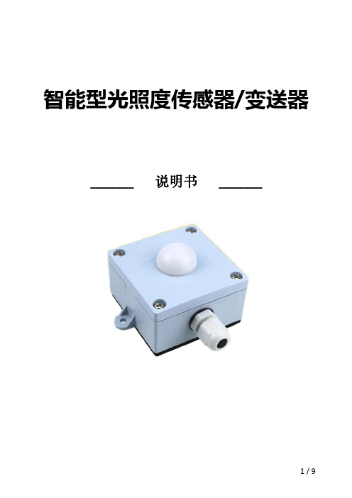
智能型光照度传感器/变送器______说明书______概述智能型光照度传感器/变送器,采用高灵敏度硅光传感器,自动衰减近红外,光谱相应接近人眼函数。
本产品能有效地对室内光照度进行测量控制。
符合欧RoHS指令,无铅、无镉标准。
有多种输出方式可选。
产品有0-1K/4K/8K/20K/200K Lux五段量程可选,用户可根据需要进行量程切换。
K33系列智能型光照度传感器/变送器,是一款室内室外可通用测量安装的现场可切换量程,外观结构简洁,小巧,安装方便,稳定性好,响应速度快。
产品配有PG7防水接头可带线缆进行连接安装,外壳防护等级可达IP65。
特点-高精度的光照度测量-体型小巧,安装方便-稳定性好,响应速度快,<2秒-传输距离长,抗外界干扰能力强-五段量程现场拨码开关可选-多种输出方式可选-出厂标准校准领域-电子厂房-机房环境监控-动力环境监控-农业环境监控-气象环境监测-生物制药环境监控-机场,地铁站,酒店,博物馆,体育馆等技术参数光照测量范围:测量精度:响应时间:光谱范围:校准:0-1K/4K/8K/20K/200K Lux(模拟输出拨码开关可选)±1%FS(0~200K Lux)±2%FS(0~20K Lux)±3%FS(0~8K Lux)±4%FS(0~4K Lux)±5%FS(0~1K Lux)<2秒320~700(nm)可见光标准校准输出参数信号输出:4~20mA R L<400ohm0~10VDC R L>10k ohm具体请参照选型表485参数信号类型:RS485类型:连接:地址:通讯协议:数据格式:波特率:RS485串口输出多点,半双工2线制,最大通讯距离1200米,端子直接连接1-254,通过开关/软件设置,广播地址为:0,默认地址为:1 MODBUS1起始位,8数据位,无奇偶,2终止位2400bit/s,4800bit/s,9600bit/s,19200bit/s,38400bit/s,通过软件设置,默认值为:9600bit/s能耗供电电源:标准供电电源24VDC供电电源范围24VDC±10%接线方式接线端子:线缆规格:5.0mm间距,M3钢螺丝,0.2Nm扭矩,0.02欧姆接触电阻24~18AWG(0.2~1.0mm2),剥线长度6-7mm环境工作环境:温度-10~70℃湿度0~99%RH,无冷凝储存环境:温度-20~80℃湿度0~95%RH,无冷凝防护等级外壳防护等级:防火等级:电磁兼容:IP65参考IEC529–598/GB700–86/GB4208 V-0参考UL94参考GB/T13926,EN61000-6-2,EN61000-6-3材料与颜色外壳:线缆长度:重量:ABS浅蓝色用户自定义约100g(整机重量)安装说明1、使用螺丝刀打开上壳的4个螺丝。
- 1、下载文档前请自行甄别文档内容的完整性,平台不提供额外的编辑、内容补充、找答案等附加服务。
- 2、"仅部分预览"的文档,不可在线预览部分如存在完整性等问题,可反馈申请退款(可完整预览的文档不适用该条件!)。
- 3、如文档侵犯您的权益,请联系客服反馈,我们会尽快为您处理(人工客服工作时间:9:00-18:30)。
光照度变送器说明
一光照度传感器:
光照度传感器、照度变送器是采用具有较高灵敏度的感光探测器,配合高精度线性放大电路,经过严密检测、生产的具有多种光照测量范围和信号输出类型的实用型产品。
变送器外壳采用壁挂安装设计,结构精致、外型美观,是一款应用范围广泛、性价比极高的光照度测量产品。
二技术参数
技术指标
量程0~2000/20000Lux
精度±5%FS(25℃)
温度漂移0.2%FS/℃
重复性<1%FS
响应时间≤60S达到变化的90%输出信号4-20mA/0~5V
RS485(Modus协议)供电电源DC12-24V
工作环境温度:0℃~50℃
湿度:≤94%RH 显示LED显示(可选)
输出负载电压输出型:>3KЛ
电流输出型:≤500R
安装方式壁挂式
三接线图
+Vs GND485_A485_B Vout Iout COM NO 电源
PC
四通信协议说明
我们的照度变送器采用MODBUS规约,原因是该规约文本容易得到,协议本身也非常的简单。
而且该规约是一个开放的,有着许多国内厂商和国际厂商的支持。
MODBUS规约是MODICOM公司开发的,版权归其所有。
根据我们设备的情况,我们仅仅实现了MODBUS的一个小型子集,没有完全实现其所有内容,已经能够满足我们所有的需要。
我们的接口采用RS485接口,比RS232具有更高的通信速率和更远的通信距离。
每个字节包括1个起始位,8个数据位,无校验位,1位停止位。
本机采用部分的MODBUS协议,使用了03和06两个命令。
可读取内部的5个寄存器变量,可写入(设置)3个寄存器变量。
4.1读取命令帧格式为(假设本机地址为1,数据均为16进制):
01030000000585C9
解释:
01:从机地址
03:读寄存器命令
0000:第一个寄存器地址
0005:读取寄存器个数
85C9:CRC校验码
采用MODBUS调试助手界面的设置如下:
如下图所示,各个寄存器内容代表含义为:
0:从机地址
1:波特率
数值与波特率的对应关系如下:
1:1200
2:2400
3:4800
4:9600(默认)
5:14400
6:19200
7:38400
8:56000
9:57600
2:报警阀值(超过报警阀值继电器就会打开)
3:报警状态(0:表示照度值没有超过报警阀值1:表示照度值超过报警阀值)4:光照度Lux值(十进制数值)
读取5个寄存器的命令(返回的数据是十六进制)
发送:01030000000585C9
返回:01030A000100042710000000922A5F
返回命令解释:
01从设备地址
03读功能号
0A返回的数据个数
0001从设备地址(第一个寄存器)
0004波特率(第二个寄存器)注:04对应波特率为9600
2710报警阀值(第三个寄存器)
0000报警状态(第四个寄存器)
0:表示照度值没有超过报警阀值1:表示照度值超过报警阀值
0092照度值(Lux)注:十六进制
2A CRC校验低8位
5F CRC校验高8位
只读取照度值的命令:
发送:010*********C5CB
返回:0103020056387A
返回命令解释:
01从设备地址
03读功能号
02返回的数据个数
0056光照度值(Lux)十六进制数值
38CRC校验低8位
7A CRC校验高8位
4.2写入命令帧格式为(假设本机地址为1,需写入的数据为10000十六进制为0X2710)
0106000227103236
解释:
01:从机地址
06:写入寄存器命令
0002:寄存器地址
2710:写入的数据为10000
32:CRC校验低8位
36:CRC校验高8位
修改报警值为10000的命令
发送:0106000227103236
返回:0106000227103236
发送命令解释:
解释:
01:从机地址
06:写入寄存器命令
0002:寄存器地址
2710:将报警阀值修改为0X2710(十进制为10000)
32:CRC校验低8位
36:CRC校验高8位
返回命令解释:
01:从机地址
06:写入寄存器命令
0002:寄存器地址
2710:修改成功后的报警阀值0X2710(十进制为10000)32:CRC校验低8位
36:CRC校验高8位
修改地址的命令:(假设本机地址为1,将地址修改为3)
发送:010*********C9CB
返回:030600000003C829
发送命令解释:
01:从机地址
06:写入寄存器命令
0000:寄存器地址
0003:将地址值修改为3
C9:CRC校验低8位
CB:CRC校验高8位
返回命令解释:
03:从机地址
06:写入寄存器命令
0000:寄存器地址
0003:修改成功后的地址值
C8:CRC校验低8位
29:CRC校验高8位
修改波特率命令:(假设本机地址为1,将波特率修改为9600)发送:010*********D9C9
返回:010*********D9C9
发送命令解释:
01:从机地址
06:写入寄存器命令
0001:寄存器地址
0004:将波特率修改为04(04对应波特率为9600)D9:CRC校验低8位
C9:CRC校验高8位
注:数值与波特率的对应关系如下:
1:1200
2:2400
3:4800
4:9600(默认)5:14400
6:19200
7:38400
8:56000
9:57600。