LPS-700同步相量测量装置说明书(2012.02.16)
PID 700 控制器说明书

Communication ModuleM 700® PID 700(X)PID Controller Module with 2 Current Outputs and 4 Relay Outputs52121217T rademarks The following registered trademarks are used in this instruction manualwithout further markingSMARTMEDIA ®is a registered trademark of Toshiba Corp., JapanF OUNDATION F IELDBUS ™is a trademark of Fieldbus Foundation, Austin, USAW arranty Defects occurring within 1 year from delivery date shall be remedied free of charge at our plant (carriage and insurance paid by sender). Sensors, fittings, and accessories: 1 year.©2007Subject to change without noticeD isposal Please observe the applicable local or national regulations concerning the disposal of “waste electrical and electronic equipment”.Warranty (2)D isposal (2)Trademarks (2)Contents (6)Intended Use (8)Conformity with FDA 21 CFR Part 11 (8)Safety Information (9)Application in Hazardous Locations: PID 700X Module (9)Software Version (10)Modular Concept (11)Short Description (12)Short Description: FRONT Module (12)Short Description: Menu Structure (13)Short Description: BASE Module (15)Terminal Plate PID 700(X) Module (16)Inserting the Module (17)Wiring Examples (18)PID Controller (20)Analog Controller IV1/IV2 (25)Digital Controller KV1/KV2 (27)Pulse Length Controller (27)Pulse Frequency Controller (27)PID Controller and Limit Contacts (28)Menu Selection (29)Menu Structure (29)Passcode Entry (30)Changing a passcode (30)Configuring the Measurement Display (31)6Parameter Setting: Operating Levels (33)Administrator level (33)Operator level (33)Viewing level (33)Parameter Setting: Lock Functions (34)Call up parameter setting (35)Documenting Parameter Setting (36)Configuring the Module (38)Maintenance (40)Diagnostics Functions (41)Call up diagnostics (42)Message list (42)Specifications (44)Index (51)78Intended UseThe module is a general-purpose PID controller module. Analog control valves are actuated via 2 passive current outputs. Digital straightway valves are actuated via 2 relay contacts. In addition, two relay contacts are provided for limit monitoring or pre-control.The PID 700X module is intended for operation in locations subject toe xplosion hazards which require equipment of Group II, device category 2(1), gas/dust.9S afety InformationA pplication in Hazardous Locations Caution!Never try to open the module! If a repair should be required, return the module to our factory.If the specifications in the instruction manual are not sufficient for assessing the safety of operation, please contact the manufacturer to make sure that your intended application is possible and safe.Application in Hazardous Locations:PID 700X ModuleWhen using the PID 700X module, the stipulations for electrical i nstallations in hazardous areas (EN 60079-14) must be observed.When installing the device outside the range of applicability of the 94/9/EC directive, the appropriate standards and regulations in the country of use must be observed. The module has been developed and manufactured in compliance with the applicable European guidelines and standards.Compliance with the European Harmonized Standards for use in hazardous locations is confirmed by the EC-Type-Examination Certificate.Compliance with the European guidelines and standards is confirmed by the EC Declaration of Conformity.There is no particular direct hazard caused by the operation of the device in the specified environment.Be sure to observe during installation:Switch off power supply before replacing or inserting a module.Before commissioning it must be proved that the device may be connected with other equipment.••S oftware VersionPID 700(X) ModuleDevice Software M 700(X)The PID 700 module is supported by software version 1.0 or higher. The PID 700X module is supported by software version 4.0 or higher. Module Software PID 700(X)Software version 1.110M odular ConceptBasic Unit, Measuring Module, Additional FunctionsThe M 700(X) is an expandable modular process analysis system.The basic unit (FRONT and BASE modules) provides three slots which can be equipped by the user with any combination of measuring or communication modules. The software capabilities can be expanded by additional functions (options). Additional functions must be ordered separately. They are supplied with a device-specific TAN for function release.M 700(X) Modular Process Analysis SystemS hort Description Short Description: FRONT Module%Air°C24.0°C25.8°CSelection of further menu items:Legend:Pressing the menu key accesses menu selection.Pressing the meas key returns to measurement.Menu groups are selected using the arrow keys.Press enter to confirm, enter passcode.Further menu items are displayed.Selected functions of the Diagnostics menu can be recalled via softkey even when in measuring mode.1)2)3)4)5)6)the SmartMedia card. The 2 internal are possible with additional softwareBASE module2 current outputs (free assignment of process variable) and 4 relay contacts, 2 digital inputs.VariPower broad-range power supply, 20 ... 265 V AC/DC, suitable for all public mains supplies in the world.Power supply units, IS version:100 ... 230 V AC or 24 V AC/DCImportant Notice Concerning SmartMedia CardThe SmartMedia card may be inserted or replaced with the power supply switched on. Before a memory card is removed, it must be “closed” in the maintenance menu. When closing the device, make sure that the sealing is properly seated and clean.M odule equipment Module identification: Plug & Play.Up to 3 modules can be combined as desired. Several input and communication modules are available.Warning!Do not touch the t erminal compartment, there may be dangerous contact voltages!Terminal Plate PID 700(X) ModuleI nserting the Module Note: Be sure to connect the s hielding properly!Switch off power supplyOpen the device (loosen the 4 screws at the front)Place module in slot (D-SUB connector)Tighten fastening screws of the module Connect signal lines.Close device, tighten screws at the front Switch on power supply Set parametersMake sure that the cable glands are tightly closed to protect against humidity.Thanks to the staggered arrangement of connectors and fastening screws the terminal strips of all modules are easy to access.1.2.3.4.5.6.7.8.Analog and Digital Controller OutputsCaution!The PID 700X module is intended for operation in locations subject toe xplosion hazards which require equipment of Group II, device category 2(1), gas/dust.Before commissioning it must be proved that the device may be connected with other equipment.For corresponding specifications, refer to EC-Type-Examination Certificate.Relay ContactsPower supply, e.g. 24 V DCLimit contactP ID Controller Short IntroductionPID control requires a closed loop. The control loop is made up of individual components which must be in permanent operation. The process variable to be controlled (controlled variable) is continuously measured and compared with the desired value (setpoint). The aim is to keep the controlled variable at the setpoint.The controlled variables (e.g. pressure, temperature, pH value, concentra-tion, ...) are measured using suitable sensors which provide the continuously measured values for comparison with the setpoint. The comparison intervals can be selected as desired. Deviations trigger a control procedure with the aim to adjust the controlled variable to the setpoint within a preset time.This comparison procedure and the calculation of the required change of the controlled variable is performed by the controller.Controllers are classified according to their characteristic, dynamic response, and mode of operation.CurveA distinction is made between continuous (linear) and discontinuous c ontrollers.Dynamic response:A change in the error variable at the controller input influences the m anipulated variable at the controller output.There is a great variety of classification criteria for linear controllers.Particular importance must be placed on their dynamic response, however. The following text describes the components of dynamic action and their typical combinations.••P Controller (Parameter: Controller Gain)The proportional-action component of a P controller transforms the control deviation (error variable) to a proportional controller output (manipulated variable). The range of the manipulated variable is limited. Therefore, also the usable range of the controller input signal (control range) is limited.Schematic Diagram of P ControllerTime response of control as reaction to a disturbance:After a short settling time a deviation x B remains.The desired value is not reached.I Controller (Parameter: Reset Time)The integral-action component takes account of the rate of change of the manipulated variable, i.e. it forms the time integral of the error variable. Each value of the controlled variable is assigned to a particular rate of change of the manipulated variable.P I ControllerThese controllers combine proportional and integral action. Compared toP controllers, which only provide a proportional relationship between con-trolled variable and manipulated variable, here an integration over time is also performed.First, the value of the manipulated variable is calculated in proportion to the error variable, and then the integral-action component is added.DControl (Parameter: Derivative)A derivative control alone is completely unsuitable since it only reacts to changes of the error variable, that is, constant errors remain unnoticed.PD ControllerThis controller adds the proportional change of the input signal and the rate of change of the controlled variable to the resulting manipulated variable.PID ControllerThis controller comprises the P , I, and D components of linear controllers. The manipulated variable of a PID control system is the sum of the output variables of a P, an I, and a D control system.The maximum overshoot of the PID controller is even smaller than that of the PD controller. Due to its I-action component there is no remaining offset. However, the components (P, I, D) of a PID controller implement a universally applicable, classical controller thanks to the fast reaction of the P compo-nent, the regulating capacity of the I component, and the attenuating effect of the D component.Typical ApplicationsP ControllerApplication for integrating control systems (e.g. closed tank, batchp rocesses).PI ControllerApplication for non-integrating control systems (e.g. drains).PID ControllerThe additional derivative action compensates for measurement peaks.C ontroller CharacteristicAnalog Controller IV1/IV2The following controller characteristics can be defined:Values are adjusted toward the setpoint.In the neutral zone (symmetrical to setpoint) no control takes place.Controller parameters: Controller gain, reset, and derivative.Feed time alarm: determines how long the controller output may be at maximum until an alarm is released. This allows recognition of a defective valve or an error in the process.Behavior during HOLD: User-defined Constant controller output (“last usablevalue”)Controller output = 0 (controller switched off)•••••P roportional Action (Gradient K C [%])10050 X w(CR: control range)C o n t r o l l erCR*0.2CR*0.4CR*0.6CR*0.8CRDeviationP ulse Length ControllerThe pulse length controller is used to operate a valve as an actuator.It switches the contact on for a time that depends on the controller output (Y). The period is constant. A minimum ON time of 0.5 sec is maintained even if the controller output takes corresponding values.Output signal (switching contact) of pulse length controllerPulse frequency (Y = 80 %)PID Controller and Limit Contacts ser-Defined VariablesUM enu SelectionAfter switching on, the analyzer performs an internal test routine and a utomatically detects the number and type of modules installed. Then, the analyzer goes to measuring mode.P asscode EntryC onfiguring the Measurement Display Select menu: Parameter setting/Module FRONT/Measurement displayPressing meas (1) returns the analyzer to the measuring mode from any function.All process variables coming from the modules can be displayed. The table on the next page describes how to configure the measurement display.7.008.06pH pH24.0°C25.8°CParameter Setting: O perating Levels Viewing level, Operator level, Administrator levelNote: HOLD mode (Setting: BASE module)Parameter Setting: L ock Functions Administrator level: Enable / lock functions for Operator level Note: HOLD mode (Setting: BASE module)A ctivating Parameter SettingCall up parameter settingDuring parameter setting the analyzer is in HOLD mode: Current outputs and relay contacts behave as configured (BASE module).You must reproducibly d ocument all parameter settings in the device to achieve a high level of system and device security according to GLP. For that purpose, an Excel file is provided (on the CD-ROM shipped with the basic device or as download at /pro) to enter the parameter settings. The Excel file provides one worksheet for each module with columns for the following parameters: Factory settings, parameter set A, parameter set B. Enter your settings as parameter set A or B.The gray cells in the parameter set B column cannot be modified since they contain sensor-specific values which cannot be changed by parameter set switchover. Here, the values listed under parameter set A apply.From the application window of the Excel file, select the worksheet for the module the parameter settings of which you want to document.Set the parameters of the respective module and enter the selected values in the corresponding cells of the module worksheet.Caution!C onfiguring the Module Activating Parameter SettingNote: HOLD mode activeParameter Setting Default Settings and Selection Range Note: HOLD mode activeM aintenanceAnalog Controller, Digital Controller Note: HOLD mode activeSelect menu: DiagnosticsGeneral status information of the measuring system Select menu: Diagnostics - Message listMessagesNo.P ID messages Message type R008Meas. processing (factory settings)FAILR009Module failure (Firmware Flash check sum)FAILR014Feed time A controller Alarm HI_HI FAILR019Feed time D controller Alarm HI_HI FAILR073Current IV1 Load error FAILR078Current IV2 Load error FAILR200Control parameters WARNR254Module reset TextS pecifications Specifications M 700 PID 700(X)Analog controllero utputs IV1, IV20/4... 20 mA, passive Supply voltage 3 ... 30 V , I max = 100 mA Load monitoring Error message if load is exceeded Measurement error **< 0,25 % current value + 0.05 mAUsageActuation of analog control valvesIV1: active below setpoint (for straightway valves)IV2: active above setpoint (for straightway valves)••Digital controller outputs KV1, KV2Electronic relay outputs, polarized, floating, connected to each other and to K9, K10Voltage drop < 1.2 VLoadability DC: V max = 30 V , I max = 100 mAUsageActuation of straightway valves, metering pumps KV1: active below setpoint KV2: active above setpoint••PID process controllerContinuous controller via the current outputs IV1, IV2 or / and quasi-continuous controller via the KV1, KV2 relayc ontacts Controlled variable *User-defined, depending on measuring modules installed (primary variables only: pH, ORP , °C, S/cm, % O 2, % Air)Setpoint specification *)As desired within range Neutral zone *As desired within rangeP action *Controller gain Kp: 0010 ... 9999 %I action *Reset time Tr: 0000 ... 9999 sec (0000 s = no integral action)D action *Rate time Td: 0000 ... 9999 sec (0000 s = no derivative action)Pulse length controller *0001 ... 0600 sec, min. ON time 0.5 sec Pulse frequency controller *0001 ... 0180 min –1Behavior during HOLD *Controller output Y = const. or controller output Y = 0Man. controller output Manual specification for testing or starting up a process,bumpless switchover to automatic whenI-action component ≠ 0000 sPulse period0001 s (pulse length controller)Switching output K9/K10Electronic relay outputs, polarized, floating,connected to each other and to KV1, KV2Voltage drop< 1.2 VLoadability DC: V max = 30 V, I max = 100 mAUsage Limit monitoring or pre-control (3-point controller),p rocess variable, threshold, hysteresis, contact type(N/C, N/O), switch on / switch off delay definable as desired * User-defined**To IEC 746 Part 1, at nominal operating conditionsSpecifications General DataExplosion protection(IS module only)ATEX:FM:CSA:See rating plate: KEMA 03 ATEX 2056 II 2 (1) GD EEx ib [ia] IIC T4 T 70 °CNI, Class I, Div 2, GP A, B, C, D T4with IS circuits extending into Division 1 Class I, Zone 2, AEx nA, Group IIC, T4 Class I, Zone 1, AEx me ib [ia] IIC, T4NI, Class I, Div 2, Group A, B, C, Dwith IS circuits extending into Division 1 AIS, Class I, Zone 1, Ex ib [ia] IIC, T4 NI, Class I, Zone 2, Ex nA [ia] IICE MCEmitted interference Immunity to interference NAMUR NE 21 andEN 61326 VDE 0843 Part 20 /01.98EN 61326/A1 VDE 0843 Part 20/A1 /05.99 Class BIndustryLightning protection EN 61000-4-5, Installation Class 2Nominal operating c onditions Ambient temperature:–20 ... +55 °C (Ex: max. +50 °C)Rel. humidity: 10 ... 95 % not condensingTransport/Storaget emperature–20 ... +70 °CS crew clamp connector Single wires and flexible leads up to 2.5 mm2。
LPS软件说明书
文档编号产品版本密级LPS-2009-02-08V 1.0公开产品名称:管道水力、热力计算软件共 49页文档作者:史博会、唐玉龙说明书校对:李晓平产品经理:李晓平日期: 2009/2/08中国石油大学(北京)油气储运系多相流实验室版权所有不得复制目录1引言 (1)1.1 编写目的 (1)1.2 参考数据 (1)2软件概述 (1)2.1 软件功能 (1)2.2 软件运行 (2)2.3 软件结构 (3)3软件使用过程 (3)3.1 进入软件 (4)3.2 基础数据准备 (4)3.3 管道物理建模 (15)3.4 进行稳态计算 (31)3.5 进行瞬态计算 (34)3.6 生成报告 (43)4软件使用技巧 (46)1引言1.1 编写目的LPS(LPS Liquid Pipeline Simulator)软件说明书能够为软件的使用者提供一个详细的软件功能和使用方法介绍。
为更好的使用本软件提供必要的技术信息。
1.2 参考数据微软软件使用说明书参考2软件概述根据模拟的时间进程与实际管道系统的运行过程是否同步,管道仿真可分为离线仿真和在线仿真。
本软件(LPS Liquid Pipeline Simulator)是离线仿真,其独立于管道系统的运行过程,只需预先给定系统的边界条件和初始条件,就可以连续地确定系统工况随时间的变化过程,而在模拟过程中不必再输人新的信息。
因此,离线仿真最适合预测未来工况,利用其超前性可以对几种运行方案进行分析及调整,从而优选出较合适的运行方案或指出给定条件下有无可行方案。
此软件的主要功能:能完成对长距离输油管道的水力和热力稳态及瞬态模拟计算。
其主要的优点:通用性较强,使用灵活方便,计算时间短,占用内存空间小,可以用来准确地模拟分析各种管网系统的稳态和瞬态过程。
2.1 软件功能本软件是管输工程技术人员对管道进行水力热力计算的必备软件。
本软件计算结果准确,稳定,操作可靠,能有效减少模拟瓶颈进行最优模拟。
南方电网同步相量测量装置配置和运行管理规定

附件:中国南方电网同步相量测量装置(PMU)配置和运行管理规定(试行)1范围本规定适用于中国南方电网PMU装置的配置和运行管理。
南方电网公司各相关部门和单位、南方电网各并网发电企业,均应遵守本规定;有关单位在南方电网开展PMU装置的设计、施工、制造、运行维护等工作时,也应遵守本规定。
2总则2.1为保证南方电网“广域测量系统”(以下简称“WAMS 系统”)的安全、可靠运行,为电网运行提供准确的动态数据和故障信息,依据《电力系统安全稳定导则》(DL755-2001)、《电网运行准则》(DL/T 1040-2007)、《电网运行规则(试行)》(电监会22号令)、《中国南方电网电力调度管理规程》(Q/CSG 2-1-1003-2008)等有关规程规定,结合南方电网实际情况,特制定本规定。
3规范性引用文件下列文件中的条款通过本标准的引用而成为本标准的条款。
凡是注日期的引用文件,其随后所有的修改单或修订版均不适用于本标准,然而,鼓励根据本标准达成协议的各方研究是否可使用这些文件的最新版本。
凡是不注日期的引用文件,其最新版本适用于本标准。
IEEE C37.118- 2005 电力系统同步相量标准ANSI/IEEE C37.111-1991 电力系统暂态数据交换通用格式DL/T 478-2001 静态继电保护及安全自动装置通用技术条件GB/T 14285-2006 继电保护和安全自动装置技术规程国家电力监管委员会5号令电力二次系统安全防护规定南方电网电力二次系统安全防护技术实施规范-2-DL 476-1992 电力系统实时数据通信应用层协议DL/T 995-2006 继电保护和电网安全自动装置检验规程DL/T 553-1994 220kV~500kV电力系统故障动态记录技术准则DL/T 663-1999 220kV~500kV电力系统故障动态记录装置检测要求4术语和定义4.1相量phasor正弦量的复数表示形式。
泓格以太网分布式IOtGW700用户使用手册
tGW-700系列中文使用手册(版本1.2, 2011年7月)目录检查配件 (1)更多信息 (1)1. 产品介绍 (2)1.1 何谓E THERNET 解决方案 (3)1.2 何谓W EB S ERVER技术 (4)2.硬件信息 (5)2.1 规格 (5)2.2 特色 (6)2.3 选型指南 (6)2.4 T GW-700配置图 (7)2.5 机构图 (9)2.6 脚位定义 (11)2.6.1 tGW-712 脚位定义 (11)2.6.2 tGW-722 脚位定义 (12)2.6.3 tGW-732 脚位定义 (13)2.6.4 tGW-715 脚位定义 (14)2.6.5 tGW-725 脚位定义 (15)2.6.6 tGW-735 脚位定义 (16)2.6.7 tGW-718 脚位定义 (17)2.6.8 tGW-724 脚位定义 (18)2.6.9 tGW-734 脚位定义 (19)2.7 RS-232/422/485接线 (20)2.7.1 RS-232 接线 (20)2.7.2 RS-422 接线 (21)2.7.3 RS-485 接线 (21)3. 启动TGW-700模块 (22)步骤1:连接电源和计算机主机 (22)步骤2:安装M ODBUS U TILITY及E S EARCH U TILITY 到您的计算机 (23)步骤3:以太网络配置设定 (24)步骤4:测试 T GW-700 (25)4. 配置网页 (29)4.1 登入T GW-700网页服务器 (29)4.2 H OME 首页 (31)4.3 N ETWORK S ETTING (32)4.3.1 Network and Miscellaneous Settings (32)4.3.2 IP Address Selection (32)4.3.3 General Configuration Settings (35)4.3.4 Restore Factory Defaults (36)4.4 P ORT1设定 (37)4.4.1 Port1 Settings (37)4.4.2 Port Settings (37)4.4.3 Pair-Connection Settings (38)4.5C HANGE P ASSWORD (39)4.6L OGOUT (39)5. TGW-700 应用 (40)5.1 M ODBUS G ATEWAY (40)5.2 P AIR-C ONNECTION应用 (41)步骤1:连接至网络、电源和计算机主机 (42)步骤2:以太网络配置设定 (43)步骤3:在 T GW-700#1网页服务器配置P AIR-C ONNECTION (43)步骤4:在 T GW-700#2网页服务器配置P AIR-C ONNECTION (45)步骤5:测试P AIR-C ONNECTION 功能 (45)附录: 相关名词 (48)1. ARP(A DDRESS R ESOLUTION P ROTOCOL) (48)2. C LIENTS/S ERVERS (48)3. E THERNET (48)4. F IRMWARE (48)5. G ATEWAY (49)6. ICMP(I NTERNET C ONTROL M ESSAGES P ROTOCOL) (49)7. I NTERNET (49)8. IP(I NTERNET P ROTOCOL) ADDRESS (49)9. MAC(M EDIA A CCESS C ONTROL) ADDRESS (49)10. P ACKET (50)11. P ING (50)12. RARP(R EVERSE A DDRESS R ESOLUTION P ROTOCOL) (50)13. S OCKET (50)14. S UBNET M ASK (50)15. TCP(T RANSMISSION C ONTROL P ROTOCOL) (51)16. TCP/IP (51)17. UDP(U SER D ATAGRAM P ROTOCOL) (51)附录: FAQ (52)1. 使用IE浏览器进入T GW-700网页服务器时,如IE浏览器画面显示为空白,请执行下列步骤。
同步相量测量装置说明书

同步相量测量装置说明书
同步相量测量装置是一种用于测量电力系统中电压、电流和相位
等参数的设备。
其主要功能是实现电气网络综合监测和故障诊断,为
电力系统运行提供数据支持。
该装置由采集单元、处理单元、通讯单元和控制单元等组成。
采
集单元负责采集电力系统中的电压、电流等参数;处理单元对采集到
的数据进行处理和分析,并进行相位测量;通讯单元可与计算机等外
部设备进行数据传输和交互;控制单元则用于装置的控制和管理。
使用同步相量测量装置,可以实现对电力系统中各个节点的电参
数进行实时监测和测量,有助于提高电力系统的运行效率和安全性。
同时,该装置还可应用于配电网、光伏发电和风力发电等领域,充分
发挥其测量和监控功能。
在进行同步相量测量时,需要注意检查装置的接地情况和采集单
元的放置位置,以确保测量结果的准确性和稳定性。
同时,也需要注
意保养和维护装置的各个部件,延长其使用寿命。
总之,同步相量测量装置是一种重要的电力系统监测和管理设备,可提供精准的数据支持和故障分析,对电力系统的稳定性和可靠性具
有重要作用。
NGP-700环网柜微机保护测控装置使用说明书资料
NGP-700环网柜保护测控装置技术说明书V2.0南京国品自动化设备有限公司目录一、概述 (1)1.1.产品适用范围 (1)1.2.产品特点 (1)1.3.产品功能配置 (1)二、主要参数和技术指标 (3)2.1.工作电源 (3)2.2.交流电流输入 (3)2.3.交流电压输入 (3)2.4.开关量输入 (3)2.5.接点输出 (3)2.6.模拟量输出(选配) (3)2.7.通讯接口 (4)2.8.环境 (4)2.9.型式试验 (4)2.10.保护功能性能指标 (4)2.11.测控功能性能指标 (5)2.12.采用的国际和国家标准 (5)三、保护控制器外观及安装 (6)3.1.安装 (6)3.2.面板功能介绍 (7)四、主要功能 (8)4.1.保护功能 (8)4.2.定值清单 (10)4.3.测控功能 (11)4.4.工程接线示意图 (11)4.5.保护压板说明 (12)NGP-700压板清单 (12)五、功能参数整定 (13)5.1.各保护功能整定 (13)5.2.系统时钟设置 (13)5.3.CAN网络设置 (13)5.4.RS-485网络设置(MODBU网) (13)七、检测及试验 (14)7.1.硬件测试 (14)7.2.保护功能试验 (14)八、面板控制器功能设置及信息查看 (16)8.1.菜单概述 (16)8.2.刻度信息查看 (17)8.3.开入查看 (18)8.4.开出检测 (19)8.5.压板投退 (19)8.6.定值整定及查看 (20)8.7.参数设定 (22)8.8.版本信息 (29)8.9.事故记录 (30)一、概述1.1. 产品适用范围NGP-700系列数字式保护测量控制器是我公司推出的400V配电系统智能化控制产品,它基于高性能ARM处理器硬件平台和嵌入式实时操作系统,集保护、控制、通讯、测量、监视功能于一身,是智能化、网络化、数字化的低压配电控制产品。
1.2. 产品特点◆安全可靠:采用PHILIPS最新的高速ARM处理器,主处理器板采用四层印制板的电气设计,高精度的AD采样,主要元件全部采用进口器件,保证了装置电气设计上的高可靠性,产品通过了严格的型式试验和电磁兼容测试,保证了产品在恶劣环境下的适应能力和可靠性。
ICP-700es 操作手册

ICP-700ES 系列电感耦合等离子光谱仪操作手册瓦里安中国有限公司前言: (4)(一)、开机 (5)1.1 冷开机(从仪器关闭状态开机) (5)1.2 热开机 (5)(二)、运行软件 (7)2.1 创建数据库: (7)2.2 在操作系统下,运行 ICPExpert (9)如下图所示: (9)2.3 进入 ICPExpert II 仪器控制软件。
(10)(三)、新建或打开工作表格 (11)3.1 打开工作表格 (11)3.2 新建一个工作表格 (13)3.2.1 建立新工作表格文件名 (13)3.2.2 打开方法编辑器编辑方法 (14)3.2.3 设置顺序参数 (22)(四)、分析前的仪器优化和检查 (26)4.1 检查炬管安装正确。
(26)4.2 关闭炬室门,确认锁紧杆完全到位。
(炬室门已关好) (26)4.3 检查进样管路安装正确 (26)4.4 点燃等离子体 (26)4.5 点燃等离子体 (27)4.6 ICP 观测位置优化 (27)(五)、分析 (29)5.1 进入或切换到分析页面。
(29)5.2 调节蠕动泵管压力 (29)5.3 选择分析标签 (29)5.4 分析 (30)(六)、打印分析结果 (31)(七)、关机 (32)7.1 冷关机 (32)7.2 待机 (32)(八)、软件结构及图标含义 (34)8.1 软件结构 (34)8.2 按钮功能 (35)8.2.1 工作表格窗口工具栏按钮功能 (35)8.2.2 仪器设置窗口工具栏按钮功能 (36)8.2.3 方法编辑窗口工具栏按钮功能 (37)8.2.4 主窗口| 分析下的图形按钮功能 (38)8.2.5 方法编辑器| 条件下的图形按钮功能 (39)(九) 术语 (40)9.1 内标(Internal Standards) (40)9.2 IEC Inter-Element Corrections(干扰元素矫正) (41)9.3 FACT Fast Automated Curve-Fitting Technique 快速自动曲线拟合技术 (43)9.4 SRS... Stability Reference Standardization(稳定性参考标准化).. (44)9.5 TRS Time Resolved Scan 时间扫描 (45)9.6 QC Test 质量控制测试项目 (46)9.6.1 概述 (46)9.6.2 QC 测试项目 (46)9.7 其它术语: (49)(十)、VSDAdministrator 数据管理 (51)10.1 软件安装过程中注意事项: (51)10.2 VSDAdministrator 软件操作: (53)10.2.1 原因说明 (53)10.2.2 登录服务器(即连接) (53)10.2.3 创建数据库 (54)10.2.4 备份数据库 (56)10.2.5 恢复数据库 (56)10.2.6 分遣数据库 (57)10.2.7 附贴数据库(文件) (58)10.2.8 信息(数据库中) (59)10.2.9 查看器 (59)10.2.10 复制文件夹 (60)10.2.11 参数选择 (61)10.2.12 服务器帐户 (61)10.2.13 数据库帐户 (62)10.2.14 日志 (63)前言:该手册是针对Varian 公司ICP-700ES 系列电感偶合等离子光谱仪所编写的一个快速参考操作手册。
同步相量测量装置说明书
同步相量测量装置说明书
同步相量测量装置说明书
一、产品概述
本产品是一种专用于高压电力系统中的同步相量测量装置。
通过对系统中的电压、电流、相位等参数进行测量,可以获得电力系统的电气状态,为系统稳定运行提供支持。
二、产品特点
1. 高精度测量:采用高精度模数转换器和数字信号处理等技术,可以实现对电压、电流和相位等参数的高精度测量。
2. 可靠性高:采用工业级扩展温度范围、抗干扰性能强的芯片和元器件,保证了装置在恶劣环境下的稳定性和可靠性。
3. 可扩展性强:支持多种接口通讯方式,可与各类设备相连接。
并且具有良好的软件扩展性,可根据用户需求进行功能扩展。
4. 显示直观:采用彩色液晶显示屏,可直观显示各种参数。
并且支持多种操作方式,方便用户进行操作和设置。
5. 体积小巧:采用全封闭结构,体积小巧、操作方便。
三、使用说明
本装置采用交流供电方式,使用前请确认电源电压与装置电源适配器符合要求。
开机后,可选择不同的参数进行测量,并可以进行参数设置,包括显示模式、报警设置、通讯参数等。
同时也支持多种通讯方式,如RS485、以太网等,可与其他设备配合使用。
四、注意事项
1. 请使用适配器提供的电源进行供电,禁止使用其他品牌或型号的电源。
2. 请勿将液晶屏暴露在阳光下或其他强光下,以防损坏屏幕。
3. 请勿将装置拆卸,以免影响使用效果和保修。
4. 请勿将装置受到强烈冲击,以免影响使用效果和稳定性。
5. 若需进行维修保养,请联系售后服务中心。
以上为本产品的说明书,如需了解更多信息,可联系生产厂家获取。
LPS系列激光测距传感器使用手册
本激光测距传感器的数据输出为标准的串行 RS-232 接口。需要配套的设备来接收数据,
9
激光测距传感器和计算机的连接图
10
单片机 或DSP
Rx CPU GND Tx
Tx GND Rx GND Vcc
激光测距传感器
8-24V直流 稳压电源
激光测距传感器和单片机或 DSP 的连接图
仪器安装
激光测距传感器与数据接口的组装: 把通讯连接线与计算机或工业控制机的串口 DB9 连接。 把电源线、串口连接线按照下表连接。
4.
05 C1 41 00 41
这样
的一串串数据输出。再点下串口软件右下方的“HEX 显示”就能看到 001.16 样一串串的数据,001.16 表示 1.16 米。 5. 6. 如果输出的数据是
这
error 表示测量失败。
其它操作可按串行通信协议定义进行操作。
串行通信协议定义如下 : 05 C1 23 00 23 是开始测量; 05 C1 24 00 24 是停止测量; 05 C1 22 01 01 24 是 1HZ 测量; 05 C1 22 01 02 25 是 10HZ 测量 ;
LPS 系列激光测距传感器是一种功能强大的测量精确、无接触式的工业用距离测量设 备,它可广泛地被集成用于各种工业用途的控制和监测系统上。使用图例如下:
被测距离 目 激光测距传感器 标
4
LPS 系列激光测距传感器是一款使用方便的工业应用激光测距仪表, 特别为交通、 炼钢、
仓储、建筑、码头等需要自动进行距离和位置控制的应用而设计研发,具有很高地实用性。
15
05 C1 22 01 03 26 是 20HZ 测量 ; 05 C1 22 01 04 27 是 50HZ 测量 ; 05 C1 22 01 05 28 是 100HZ 测量; 05 C1 12 01 55 68 是开激光指示灯; 05 C1 12 01 AA BD 是关激光指示灯; 05 C1 41 00 41 是 FLOAT 型十进制输出; 05 C1 40 00 40 是 FLOAT 型十六进制格式输出;
700系列xDSL测试仪说明书V1.4
SGT-700系列xDSL测试仪使用说明书V1.4目录一、概述 (1)二、主要功能及技术指标 (2)2.1 X DSL测试技术指标 (2)2.2误码测试功能 (3)2.3拨号测试功能 (3)2.4PING测试功能 (4)2.5DMM测试指标(本功能700C款特有) (4)2.6测试数据的存储与浏览功能 (5)2.7M ODEM仿真功能 (5)2.8系统参数配置功能 (5)2.9线路电压指示功能 (5)3.10尺寸及重量 (6)三、产品结构及外观 (7)四、使用前须知 (9)五、操作说明及步骤 (10)5.1仪器开机 (10)5.2仪器关机 (10)5.3液晶对比度调整 (11)5.4背光功能 (11)5.5系统初始化 (11)5.6系统配置 (12)5.7 X DSL测试功能 (14)5.7.1 物理层连接参数的测试功能 (15)5.7.2测试记录的保存功能 (17)5.8误码测试功能 (18)5.9拨号测试功能 (20)5.9.1 PPPoE/PPPoA拨号设置 (22)5.9.2 查看PPPoE/PPPoA拨号信息 (24)5.10PING测试功能 (26)5.10.1 查局域网ping测试 (26)5.10.2 广域网Ping测试 (28)5.11DMM测试功能(本功能为700C款特有) (31)5.11.1 电压测试 (32)5.11.2 环阻测试 (33)5.11.3 电容测试 (34)5.11.4 绝缘测试 (35)5.12存储浏览功能 (36)5.13仿真M ODEM功能 (39)5.13.1仿真Modem 测试,Bridging 模式 (39)5.13.2仿真Modem 测试,Routing 模式 (40)5.14线路电压指示功能 (41)5.15电池充电 (42)六、简易故障分析与排除 (42)七、后台管理维护软件使用说明 (43)7.1软件菜单说明 (43)7.2软件工具栏说明 (44)7.3软件操作说明 (45)7.3.1 读取物理层连接参数 (45)7.3.2 读取修改ATM VC参数 (46)7.3.3 读取修改PPPoE认证信息 (47)八、附件 (48)一、概述我公司生产的SGT-700系列xDSL测试仪是在长期与各通信企业的合作中听取用户的使用意见而推出的专门用于xDSL (ADSL2+、ADSL2、READSL、ADSL等)业务的开通、维护和测试的手持式通信仪表,是针对于通信行业一线安装维护人员使用的智能化仪表。
LPS软件说明书

文档作者:史博会、唐玉龙说明书校对:李晓平产品经理:李晓平日期:2009/2/08中国石油大学(北京)油气储运系多相流实验室版权所有不得复制目录1引言 (1)1.1 编写目的 (1)1.2 参考数据 (1)2软件概述 (1)2.1 软件功能 (1)2.2 软件运行 (2)2.3 软件结构 (3)3软件使用过程 (3)3.1 进入软件 (4)3.2 基础数据准备 (4)3.3 管道物理建模 (16)3.4 进行稳态计算 (32)3.5 进行瞬态计算 (35)3.6 生成报告 (44)4软件使用技巧 (47)1引言1.1 编写目的LPS(LPS Liquid Pipeline Simulator)软件说明书能够为软件的使用者提供一个详细的软件功能和使用方法介绍。
为更好的使用本软件提供必要的技术信息。
1.2 参考数据微软软件使用说明书参考2软件概述根据模拟的时间进程与实际管道系统的运行过程是否同步,管道仿真可分为离线仿真和在线仿真。
本软件(LPS Liquid Pipeline Simulator)是离线仿真,其独立于管道系统的运行过程,只需预先给定系统的边界条件和初始条件,就可以连续地确定系统工况随时间的变化过程,而在模拟过程中不必再输人新的信息。
因此,离线仿真最适合预测未来工况,利用其超前性可以对几种运行方案进行分析及调整,从而优选出较合适的运行方案或指出给定条件下有无可行方案。
此软件的主要功能:能完成对长距离输油管道的水力和热力稳态及瞬态模拟计算。
其主要的优点:通用性较强,使用灵活方便,计算时间短,占用内存空间小,可以用来准确地模拟分析各种管网系统的稳态和瞬态过程。
2.1 软件功能本软件是管输工程技术人员对管道进行水力热力计算的必备软件。
本软件计算结果准确,稳定,操作可靠,能有效减少模拟瓶颈进行最优模拟。
具体用途如下:(1)能够实现管线的物理建模,实现管道的数字化和抽象化。
(2)能够实现设备仿真,具体设备包括:离心泵、泄压阀、截断阀、油罐、单向阀、加热炉、调节阀等。
气体检测仪700系列说明书

DescriptionModel 700 Series Sensors are a non-intrusive “Smart” sensors designed to detect and monitor oxygen and Toxic Gases in air using electrochemical sensor technology.The intelligent plug-in, field replaceable cell provides automatic recognition of gas type and range, and features over-sized gold-plated connections that help prevent corrosion.The Model 700’s rugged framework includes an intrinsically safe electro-polished 316 stainless steel housing with fully encapsulated electronics and dual layer surge protection.This innovative design virtually eliminates sensor failure due to water in-gress, corrosion, vibration, and transient spikes.A primary feature of the Model 700 is embedded intuitive software that simplifies operator interface by guiding the user through routinecalibration, configuration, and fault diagnostic functions using a built-in alpha/numeric display.The Model 700 is equipped with standard analog 4-20mA, and Modbus™ RS-485 outputs. Among its unique features is a wireless option that can be used with Detcon’s SmartWireless® product line. Additional integration options include a Remote Alarm Module (RAM) and HART.Detcon’s toxic gas and oxygen sensors have a long shelf life and are sup-ported by an industry-leading warranty.Model DM 700Toxic gas sensorsFeaturesFailsafe User-Friendly Interface• LED Display (With Antiglare Cover)• Full Text Display Method • Non-intrusive Interface • Auto Zero/Auto Span• Pre-emptive Fault DiagnosticsEnvironmentally Bulletproof• Electropolished 316SS Construction • 100% Epoxy Encapsulated Circuitry • Bulletproof I/O Protection• Water-proof, Corrosion-Proof, Vibration-ProofModular and Serviceable • Modular Design• Plug and Play Components• Quick Thread Release Sensor Endcap (Allen Wrench only required)• Integral Calibration PortApplications• Oil & Gas• Chemical Plants • Food & Beverage • Steel Mills • Pulp and Paper • Refineries• Wastewater Treatment Plants •Utilities(shown as PN 967-505094-100 in SS junction box)Gas Part Number Warranty Measuring Accuracy Response Time Operating Temp Storage Temp Operating Humidity Acetylene (*See Note)967-12EG91-100 2 years0-100 ppm±2% FS T90≤140 seconds-4 to 122ºF/-20 to 50ºC-31 to 131ºF/-35 to 55ºC15-90% RH non-condensing Ammonia967-505091-100 2 years0-100 ppm±2% FS T90≤90 seconds-40 to 122ºF/-40 to 50ºC-31 to 131ºF/-35 to 55ºC15-90% RH non-condensing Arsine967-191991-001 1.5 years0-1 ppm±2% FS T90≤60 seconds-4 to 104ºF/-20 to 40ºC-31 to 131ºF/-35 to 55ºC20-95% RH non-condensing Bromine967-747591-005 2 years0-5 ppm±2% FS T90≤60 seconds-4 to 122ºF/-20 to 50ºC-31 to 131ºF/-35 to 55ºC15-95% RH non-condensing Butadiene967-12EB91-100 2 years0-100 ppm±2% FS T90≤140 seconds-4 to 122ºF/-20 to 50ºC-31 to 131ºF/-35 to 55ºC15-90% RH non-condensingCarbon Monoxide967-444491-100 3 years0-100 ppm±2% FS T50≤10 sec./T90≤30 sec.-40 to 122ºF/-40 to 50ºC-31 to 131ºF/-35 to 55ºC15-90% RH non-condensingChlorine967-747491-010 2 years0-10 ppm±2% FS T90≤60 seconds-4 to 122ºF/-20 to 50ºC-31 to 131ºF/-35 to 55ºC15-90% RH non-condensing Chlorine Dioxide 700967-747691-050 2 years0-50 ppm±2% FS T90≤120 seconds-4 to 104ºF/-20 to 40ºC-31 to 131ºF/-35 to 55ºC10-95% RH non-condensing Chlorine Dioxide 701967-777791-001 2 years0-1 ppm±2% FS T90≤60 seconds-4 to 104ºF/-20 to 40ºC-31 to 131ºF/-35 to 55ºC15-90% RH non-condensing Diborane967-192191-005 1.5 years0-5 ppm±2% FS T90≤60 seconds-4 to 104ºF/-20 to 40ºC-31 to 131ºF/-35 to 55ºC20-95% RH non-condensing Ethanol967-12EO91-100 2 years0-100 ppm±2% FS T90≤140 seconds-4 to 122ºF/-20 to 50ºC-31 to 131ºF/-35 to 55ºC15-90% RH non-condensing Ethylene (*See Note 2)967-12ED91-100 2 years0-100 ppm±2% FS T90≤140 seconds-4 to 122ºF/-20 to 50ºC-31 to 131ºF/-35 to 55ºC15-90% RH non-condensing Ethylene Oxide967-12EJ91-100 2 years0-100 ppm±2% FS T90≤140 seconds-4 to 122ºF/-20 to 50ºC-31 to 131ºF/-35 to 55ºC15-90% RH non-condensing Fluorine967-272791-001 1.5 years0-1 ppm±2% FS T90≤80 seconds14 to 104ºF/-10 to 40ºC-31 to 131ºF/-35 to 55ºC10-95% RH non-condensing Formaldehyde967-12EP91-100 2 years0-100 ppm±2% FS T90≤140 seconds-4 to 122ºF/-20 to 50ºC-31 to 131ºF/-35 to 55ºC15-90% RH non-condensing Germane967-232591-002 1.5 years0-2 ppm±2% FS T90≤60 seconds-4 to 104ºF/-20 to 40ºC-31 to 131ºF/-35 to 55ºC20-95% RH non-condensing Hydrogen (1%)967-070791-01P 2 years0-1%volume±2% FS T90≤60 seconds-40 to 104ºF/-40 to 40ºC-31 to 131ºF/-35 to 55ºC5-90% RH non-condensing Hydrogen (4%)967-050591-04P 2 years0-4%±2% FS T90≤60 seconds-40 to 104ºF/-40 to 40ºC-31 to 131ºF/-35 to 55ºC5-95% RH non-condensing Hydrogen PPM967-848491-100 2 years0-100 ppm±2% FS T90≤30 seconds-4 to 122ºF/-20 to 50ºC-31 to 131ºF/-35 to 55ºC15-90% RH non-condensing Hydrogen Bromide967-090891-030 1.5 years0-30 ppm±2% FS T90≤70 seconds-4 to 104ºF/-20 to 40ºC-31 to 131ºF/-35 to 55ºC10-95% RH non-condensing Hydrogen Chloride967-090991-030 1.5 years0-30 ppm±2% FS T90≤70 seconds-4 to 104ºF/-20 to 40ºC-31 to 131ºF/-35 to 55ºC10-95% RH non-condensing Hydrogen Cyanide967-131391-030 2 years0-30 ppm±2% FS T90≤40 seconds-40 to 104ºF/-40 to 40ºC-31 to 131ºF/-35 to 55ºC5-95% RH non-condensing Hydrogen Fluoride967-333391-010 1.5 years0-10 ppm±2% FS T90≤90 seconds-4 to 95ºF/-20 to 35ºC-31 to 131ºF/-35 to 55ºC10-80% RH non-condensingHydrogen Sulfide967-242491-100 2 years0-100 ppm±2% FS T50≤10 sec./T80≤30 sec.-40 to 122ºF/-40 to 50ºC-31 to 131ºF/-35 to 55ºC5-90% RH non-condensingHydrogen Sulfide (DC)*967-303091-1002 years0-100 ppm±10%applied gasconcentrationor ±3 ppm,whichever isgreaterT20 ≤ 20sec-40 to +131°F/-40 to +55°C -31 to +131°F/-35 to +55°C5-90% RH non-condensing 967-303091-050T50 ≤ 45 sec967-303091-025 T90 ≤ 60 secMethanol967-12EE91-100 2 years0-100 ppm±2% FS T90≤140 seconds-4 to 122ºF/-20 to 50ºC-31 to +131ºF/-35 to 55ºC15-90% RH non-condensing Methyl Mercaptan967-12EK91-100 2 years0-100 ppm±2% FS T90≤45 seconds-40 to 122ºF/-40 to 50ºC-31 to +131ºF/-35 to 55ºC15-90% RH non-condensing Nitric Oxide967-949491-100 3 years0-100 ppm±2% FS T90≤10 seconds-4 to 122ºF/-20 to 50ºC-31 to +131ºF/-35 to 55ºC15-90% RH non-condensing Nitrogen Dioxide967-646491-010 2 years0-10 ppm±2% FS T90≤40 seconds-4 to 122ºF/-20 to 50ºC-31 to +131ºF/-35 to 55ºC15-90% RH non-condensingOxygen967-341520-025 2 years 0-25%volume±1% FS T90≤10 seconds-4 to 122ºF/-20 to 50ºC-40 to 122ºF/ -40 to 50ºC15-90% RH non-condensingOzone967-393991-001 2 years0-1 ppm±2% FS T90≤120 seconds14 to 104ºF/-10 to 40ºC-31 to +131ºF/ -35 to 55ºC10-95% RH non-condensing Phosphine967-192091-005 1.5 years0-5 ppm±2% FS T90≤30 seconds-4 to 104ºF/-20 to 40ºC-31 to +131ºF/ -35 to +55ºC20-95% RH non-condensing Silane967-232391-050 1.5 years0-50 ppm±2% FS T90≤60 seconds-4 to 104ºF/-20 to 40ºC-31 to 131ºF/ -35 to +55ºC20-95% RH non-condensing Sulfur Dioxide967-555591-020 2 years0-20 ppm±2% FS T90≤20 seconds-4 to 122ºF/-20 to 50ºC-31 to +131ºF/ -35 to +55ºC15-90% RH non-condensing *Note: Acetylene can only be used with a Group A enclosure.*Note2: This product is a safety device to detect hazardous conditions, and is not intended for process control application in fruit ripening operations.*Note3: DC=Desert Climate Sensors are 3rd-party test report to ISA 92.00.01 2010 standardSystem specifications Sensor TypeContinuous diffusion/adsorption3-electrode electrochemical cellPlug-in field replaceable Intelligent Type OutputsLinear 4-20 mA DCRS-485 MODBUS-RTUElectrical ClassificationExplosion proofC CSAUSClass I, Division 1, Groups B, C, D ()Class I, Zone 1, Group IICATEXII 2 G Ex d ib IIB + H2 T4 GBIngress ProtectionNEMA 4X, IP66Safety ApprovalscCSAusATEXCE MarkingSIL2 Certified to IEC 61508* Specifications subject to change without noticeOrder guidePN 967 - _ _ _ 090 - _ _ z DM - 700 Sensor Assembly (no junction box) PN 967 - _ _ _ 091 - _ _ z DM - 700 Sensor Assembly with Aluminum J-Box PN 967 - _ _ _ 094 - _ _ z DM - 700 Sensor Assembly with 316 SS J-Box _ = Any character as shown in table on prior pagez = Code for Regulatory Approval Required, C for CSA or A for ATEX, others available.C for CSA or A for ATEX Mechanical specificationsDimensions7”H x 2.2” Dia.; 178mmH x 65mm Dia. (sensor assembly only)11”H x 6.1”W x 3.75”D; 280mmH x 155mmW x 96mmD (with junction box) Mounting holes (J-box) 5.5”; 140mm center to centerWeight2 lbs; 0.907kg (sensor only)6 lbs; 2.72kg (w/aluminum j-box)9 lbs; 4.08kg (w/stainless steel j-box)Electrical specificationsPower Input11 - 30 VDCPower ConsumptionNormal operation = 30mA @ 24V (<0.75 watt)Maximum = 50mA @ 24V (1.2 watts)Inrush Current500mA @ 24V (typical)RFI/EMI ProtectionComplies with EN50270Analog OutputLinear 4-20mA DC (1,000 ohms max loop load @ 24VDC)0mA All Fault Diagnostics2mA In-Calibration4-20mA 0-100% full-scale22mA Over-range conditionSerial RS-485 OutputRS-485 Modbus™ RTUBaud Rate9600 BPS (9600, N, 8, 1 Half Duplex)Status Indicators4-digit LED display with gas concentrationFull-script menu prompts for AutoSpan,Set-up Options, and Fault ReportingFaults MonitoredLoop, Input Voltage,Missing Sensor, Zero,Processor, Memory, CalibrationCable RequirementsPower/Analog3-wire shielded cableMaximum distance is 13,300 feet with 14 AWGSerial Output2-wire twisted-pair with ground, shielded communicationcable specifically for use with RS-485 installationsMaximum distance is 4,000 feet to last sensorI/O ProtectionOver -voltage, Miswiring, EMI/RFI ImmunityIntegration optionsThe first three characters of the PN define the Integration options as follows:PN 9R7 - Remote Alarm Module (Remote Operation and 2 Alarm Relays plus Fault)PN 9H7- Hart Integration Module (Hart Communication Protocol version 7.0, HART Registered)PN 9K7- Combination HART / Remote Alarm Module (Combines the features of both into one module)Copyright © 2020 Teledyne Technologies. All rights reserved. **********************************************AMERICAS4055 Technology Forest Blvd.The Woodlands, TX 77381USATel.: +1 713-559-9200Fax: +1 713-893-6729EMEAZI Est, Rue Orfila,CS 2041762027 ARRAS CEDEX, France Tel.: +33-3-21-60-80-80Fax: +33-3-21-60-80-00ASIA PACIFIC290 Guiqiao RoadPudong, Shanghai 201206People's Republic of China Tel.: +86-21-3127-6373Fax: +86-21-3127-6365Teledyne Gas & Flame Detection quality assurance programmes demand the continuous assessment and improvement of all our products. Information in this leaflet could thus change without notification and does not constitute a product specification. For more informa-tion, please contact us or your company representative。
PI-700(ok)说明书
DETCON PI-700系列目录1.介绍2.安装3.操作4.RS-485通讯接口协议5.保养和维修6.故障诊断及处理7.客服支持8.PI-700系列质保9.附录1.介绍1.1 产品描述DETCON的PI-700系列的VOC气体探测器无干扰,智能型的,被设计用于监视空气环境中宽量程的VOC和有毒气体,探测范围有0-1PPM至0-5000PPM。
探测器的LED显示屏现场读数和FAULT、CAL的状态。
探测器有标准的4-20MA和RS-485输出。
其中最重要的一个特征是探测器采用自动标定的方法,它通过带背光的液晶显示屏(LCD)的指示,让用户完成所有操作步骤。
这个电子微处理器安装在一个防爆型的外壳里面,被称为ITM(智能型传感器模块)。
ITM包括一个4位的数字LED显示屏用来显示传感器读数,并通过一个手持的磁棒来完成探测器所有菜单的操作。
1.2 传感器电路设计智能型传感器模块PI-700的ITM是以微处理器为基础,完全环氧树脂密封,通用型设计,能与任何现场即插式VOC传感器相配。
这个ITM设计用一个内部本质安全的安全栅电路和火焰捕捉器,达到Division 1、Zone 1等级。
这些配置加快了反应速度,并对一些吸收强的气体提高了标定的稳定性。
其电路功能包括I/O接口电路保护,提供底板电压,内部本质安全栅电路,微处理器,LED显示屏,磁棒操作开关,线性4-20mADC的输出以及RS-485的输出。
磁性编程开关位于LED显示屏两侧,并通过一个手持的磁棒进行编程,因此ITM具有无干扰的用户操作界面。
标定也无需在特定的环境下进行。
其适用电气类别有Class I、Division 1、Group B,C,D和Class I、Zone 1、Group IIB+H2。
图1. ITM电路功能框图图2 探测器装配正视图1.3 模块机构设计PI-700型系列探测器完全是模块化集结,它由4个部分组成(见图3的分装图):1)PI-700智能传感器模块(ITM)2)可现场更换的即插式VOC气体传感器3)700型外壳底座(包括底座,定位环和像胶环)4)防溅罩注意:所有的金属部件都是由316SS不锈钢制成,在恶劣的环境中有最强的耐腐蚀性。
LPS-700同步相量测量装置说明书(2012.02.16)
LPS-700同步相量测量装置技术说明书编制:孟新校核:宁元元审定:于浩技术支持电话:(025)86728200市场部电话:(025)52103712传真:(025)52103712网址http://www.jshrt.c om版权所有:江苏华瑞泰科技股份有限公司2012.02(Ver2.2)注:本公司保留对此说明书修改的权利。
如果产品与说明书有不符之处,请您及时与我公司联系,我们将为您提供相应的服务。
目录第1章LPS-700系统概述 (1)1.1 LPS-700开发背景 (1)1.2 LPS-700系统特点 (1)1.3 LPS-700技术创新 (2)1.4 同步相量测量技术 (2)第2章PMU测量系统体系结构概述 (4)2.1 PMU测量系统体系结构组成 (4)2.2 主站系统体系结构 (4)2.3 PMU子站装置体系结构 (5)2.4 通道接口及网络系统 (6)第3章LPS-700同步相量测量装置的技术指标 (7)3.1 LPS-700同步相量测量装置功能 (7)3.2 LPS-700同步相量测量装置的技术条件 (7)3.2.1 环境条件 (7)3.2.2 绝缘性能 (7)3.2.3 电磁兼容性 (8)3.2.4 机械性能 (8)3.2.5 安全性能 (9)3.2.6 热性能(过载能力) (9)3.2.7 输出触点容量 (9)3.3 LPS-700同步相量测量装置的功能指标 (9)第4章LPS-700同步相量测量装置原理 (11)4.1 概述 (11)4.2 LPS-700装置硬件单元组成 (11)4.3 PMU装置数据流 (11)4.4 PMU装置的同步 (12)4.5 PMU装置的测量数据类型 (12)4.6 PMU装置的稳态(动态)测量 (12)4.7 PMU装置的暂态测量 (12)4.8 发电机功角δ的测量原理 (13)第5章计算方法 (15)5.1 软件自适应频率跟踪计算法 (15)5.2 相量计算 (15)5.3 序量计算 (16)5.4 高次谐波相量计算 (18)5.5 功率及相角计算 (18)5.6 平均值计算 (19)5.7 突变量计算 (19)5.8 变化率(滑差)计算 (20)第6章LPS-700同步相量测量装置的硬件部分 (21)6.1 装置的结构布局 (21)6.2 装置的硬件结构 (22)6.3.1 非智能插件 (22)6.3.2 智能插件 (23)第7章相量数据集中器PDC单元 (27)7.1 PDC相量数据集中器功能 (27)7.2 PDC相量数据集中器性能 (27)7.2.1 技术参数 (27)7.2.2 接线端子及前面板指示灯 (28)7.3 动态数据文件名命名规则 (29)第8章通过彩色触摸屏使用装置 (30)8.1 概述 (30)8.2 装置面板 (30)8.2.1 主机面板包括 (30)8.2.2 扩展装置面板灯 (30)8.3 触摸屏 (31)8.3.1 开机界面 (31)8.3.2 实时数据显示 (32)8.3.3 定值整定界面 (34)8.3.4 整组试验界面 (38)8.3.5 异常查询界面 (39)第9章通过本地工作站使用装置 (41)9.1 本地监视工作站概述 (41)9.2 数据分析软件 (42)9.3 PMU模拟软件 (43)9.4 客户端软件 (44)9.4.1 PDC软件-LINUX版 (44)9.4.2 主站监控系统 (44)9.4.3 数据分析软件 (51)9.4.4 PMU模拟软件 (54)第10章LPS-700同步相量测量装置暂态录波说明 (55)10.1 暂态数据文件名命名规则 (55)10.2 记录方式及采样频率 (55)10.3 录波启动判据 (56)10.3.1 电压判据 (56)10.3.2 电流判据 (57)10.3.3 频率判据 (58)10.3.4 其它判据 (59)10.3.5 关于长期越限启动的说明 (59)第11章安装调试 (60)11.1 装置调试方法简介 (60)11.2 对测试仪器的要求 (60)11.3 装置的一般检验 (60)11.4 运行前检查 (61)第12章定货与维护 (62)12.2 产品包装 (62)12.3 运输条件 (62)12.4 贮存条件 (62)12.5 保修时间 (62)12.6 供应成套性 (62)12.7 产品附件 (63)12.8 订货须知 (63)附录1:PMU装置插件布置图 (64)附录2: 屏后端子图 (65)第1章LPS-700系统概述1.1LPS-700开发背景电力系统中两种传统的监测方法都存在一定的不足。
pws700s说明书
pws700s说明书
一、通电前检查
1、核对保护装置背面的产品铭牌中的工作电压、控制电源、交流电流、电压额定值等参数是否与订货单一致,如果不一致请与本公司联系。
2、装置的接地线必须可靠接入开关柜的接地线,不允许将开关柜前面板与柜体的连接轴作为接地连接,并且接地线必须满足低阻抗要求(小于1欧姆)。
二、投运检查及说明
1、检查装置各电缆及背后端子是否连接固定可靠。
2、通电后液晶和指示灯显示是否正常。
3、开入量输入检查:进入“开关量状态”菜单、按设计图纸对实际接入的开关量逐一进行变位试验,检查画面显示与实际状态是否一致。
4、开出量:菜单中传动各继电器动作是否一致。
5、模拟量输入检查:从开关柜(PK屏)的交流电流(5A)输入端加入额定值,进入“开关量状态”菜单、按设计图纸对实际接入的开关量逐一进行变位试验,检查画面显示与实际状态是否一致。
6、第一次运行产品时,必须进行相关定值整定才能确保保护装置正常运行。
7、保护定值按电力调度定值整定通知单整定,定值单所有保护定值整定好后,核对无误后存档。
(未要求的保护项目设定退出)。
键相测量和传感器安装

LPS-700PMU简介-键相脉冲实测波形
(1)汽轮机键相脉冲额定频率50Hz (2)通常为负电平信号,部分电厂为TTL正电平信号, 脉冲幅值个体差异较大,与传感器外接电源有关脉冲 宽度个体差异大,与发电机转速及齿槽大小有关
LPS-700PMU简介-汽轮机键相传感器安装
汽轮机转子轴开有键相齿槽 传感器用固定支架安装 传感器线缆就近接入端子箱(根据需要续接普通电缆) 传感器电源由PMU装置提供
NGP-700环网柜微机保护测控装置使用说明书资料

NGP-700环网柜保护测控装置技术说明书V2.0南京国品自动化设备有限公司目录一、概述 (1)1.1.产品适用范围 (1)1.2.产品特点 (1)1.3.产品功能配置 (1)二、主要参数和技术指标 (3)2.1.工作电源 (3)2.2.交流电流输入 (3)2.3.交流电压输入 (3)2.4.开关量输入 (3)2.5.接点输出 (3)2.6.模拟量输出(选配) (3)2.7.通讯接口 (4)2.8.环境 (4)2.9.型式试验 (4)2.10.保护功能性能指标 (4)2.11.测控功能性能指标 (5)2.12.采用的国际和国家标准 (5)三、保护控制器外观及安装 (6)3.1.安装 (6)3.2.面板功能介绍 (7)四、主要功能 (8)4.1.保护功能 (8)4.2.定值清单 (10)4.3.测控功能 (11)4.4.工程接线示意图 (11)4.5.保护压板说明 (12)NGP-700压板清单 (12)五、功能参数整定 (13)5.1.各保护功能整定 (13)5.2.系统时钟设置 (13)5.3.CAN网络设置 (13)5.4.RS-485网络设置(MODBU网) (13)七、检测及试验 (14)7.1.硬件测试 (14)7.2.保护功能试验 (14)八、面板控制器功能设置及信息查看 (16)8.1.菜单概述 (16)8.2.刻度信息查看 (17)8.3.开入查看 (18)8.4.开出检测 (19)8.5.压板投退 (19)8.6.定值整定及查看 (20)8.7.参数设定 (22)8.8.版本信息 (29)8.9.事故记录 (30)一、概述1.1. 产品适用范围NGP-700系列数字式保护测量控制器是我公司推出的400V配电系统智能化控制产品,它基于高性能ARM处理器硬件平台和嵌入式实时操作系统,集保护、控制、通讯、测量、监视功能于一身,是智能化、网络化、数字化的低压配电控制产品。
1.2. 产品特点◆安全可靠:采用PHILIPS最新的高速ARM处理器,主处理器板采用四层印制板的电气设计,高精度的AD采样,主要元件全部采用进口器件,保证了装置电气设计上的高可靠性,产品通过了严格的型式试验和电磁兼容测试,保证了产品在恶劣环境下的适应能力和可靠性。
同步相量测量装置 93页PPT

0+6/8 0 1+6/8 1 2+6/8 2 3+6/8 3 4+6/8 4 5+6/8 5 6+6/8 6 7+6/8 7
0+7/8 0 1+7/8 1 2+7/8 2 3+7/8 3 4+7/8 4 5+7/8 5 6+7/8 6 7+7/8 7
35
1)假设 f f0,则 s 0 在任何时刻永久不变
0+3/8 0 1+3/8 1 2+3/8 2 3+3/8 3 4+3/8 4 5+3/8 5 6+3/8 6 7+3/8 7
0+4/8 0 1+4/8 1 2+4/8 2 3+4/8 3 4+4/8 4 5+4/8 5 6+4/8 6 7+4/8 7
0+5/8 0 1+5/8 1 2+5/8 2 3+5/8 3 4+5/8 4 5+5/8 5 6+5/8 6 7+5/8 7
3
PMU国内外概况
4
国内外概况
应用背景1: 经济及电力发展的需求
1) 全球经济一体化;能源分布和经济发展的不平衡;电网 互联运行的巨大效益使大电网互联、跨国联网输电 的趋势不断发展。
2) 电网互联产生电网稳定运行问题日益突出,提出构建 WAMS系统(Wide Area Measurement System). 目前国内大多数将其作为除保护/安控装置外的第三道 防线;
8
3)成熟的PMU技术 (1)各个厂商的PMU已经在变电站/电厂广 泛使用,并在内电势测量技术方面取得 很好的进展 (2)国内的PMU性能优于国外的PMU
同步相量测量系统(PMU)单体调试报告
同步相量测量系统(PMU)单体调试报告
1 概述
大唐清苑热电项目同步相量测量系统(PMU),分别设置同步相量采集屏和同步相量管理屏各一面。
公用电子间内的同步相量管理屏配置两台同步数据采集单元,用于测量两条220kV 线路的三相电压、电流;两台数据集中处理单元,用于完成数据处理、远方通信和数据存储;同屏还配置GPS授时单元及数据集中处理单元各一台,用于GPS对时及数据分析。
电子设备间内的同步相量采集屏内配置一台同步相量采集单元和两台内电势测量单元,用于测量两台机组机端三相电压、电流、发电机内电势、键相脉冲信号及励磁电压、电流等。
2 调试目的
本次单体调试确保实时动态监测系统子站PMU系统可靠投入运行,配合省调度部门更好掌握电网系统安全稳定运行状况。
3 功能校验
3.1装置一般性检查
电源检查:拉合电源开关三次,装置工作正常,无异常报警,电源缓慢上升和下降试验过程中保护装置无异常,80%额定电压下逆变电源可靠启动。
3.5开入量检查
4 结论
经检验调度要求的各个监测量均已接入PMU装置,且与调度通讯正常,模拟各检测量输入,调度画面能够正确显示。
LPS_Core操作手册
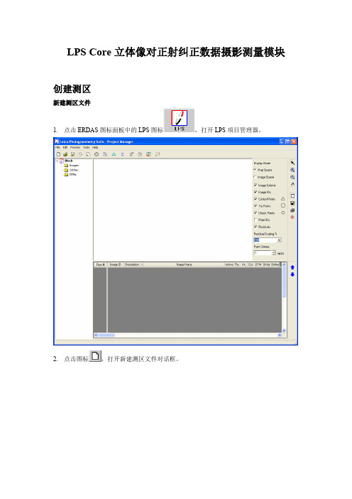
LPS Core立体像对正射纠正数据摄影测量模块创建测区新建测区文件1.点击ERDAS图标面板中的LPS图标,打开LPS项目管理器。
2.点击图标,打开新建测区文件对话框。
3.在File Name文本框中输入测区文件名后按回车建。
4.点击OK按钮,关闭新建测区文件对话框,同时自动打开建立相机模型对话框。
选择相机模型1.点击Geometric Model Category下拉列表并选择Polynomial-based Pushbroom列表项。
2.在Geometric Model中选择SPOT Pushbroom。
3.点击OK关闭创建模型对话框。
弹出创建测区属性对话框。
4.在创建测区属性对话框中的Horizontal Reference Coordinate栏中点击Set按钮,弹出选择投影对话框(Projection Chooser)5.在Custom选项卡中,点击Projection Type下拉列表并选择UTM.6.点击Spheroid Name下拉列表并选择Clarke 1866。
7.7.点击Datum Name下拉列表并选择NAD27(CONUS)。
8.点击UTM Zone并键入11.9.确定NORTH or SOUTH项设定为NORTH。
10.在(Edited) Projection Chooser对话框中点击OK按钮。
11.确定Horizontal Units设置为Meters.12.点击OK,关闭Block Property Setup对话框。
向测区中添加影像1.在LPS工程管理器左边的测区工程目录视图(Block Project Tree View)中,点击Images文件夹。
2.在LPS工程管理器的菜单中选择选择Edit | Add Frame或点击添加影像图标,打开影像文件名称对话框(Image File Name dialog).3.打开文件夹/examples/LPS/spot并选择影像文件spot_pan.img后点击OK按钮。
- 1、下载文档前请自行甄别文档内容的完整性,平台不提供额外的编辑、内容补充、找答案等附加服务。
- 2、"仅部分预览"的文档,不可在线预览部分如存在完整性等问题,可反馈申请退款(可完整预览的文档不适用该条件!)。
- 3、如文档侵犯您的权益,请联系客服反馈,我们会尽快为您处理(人工客服工作时间:9:00-18:30)。
LPS-700同步相量测量装置技术说明书编制:孟新校核:宁元元审定:于浩技术支持电话:(025)86728200市场部电话:(025)52103712传真:(025)52103712网址版权所有:江苏华瑞泰科技股份有限公司2012.02(Ver2.2)注:本公司保留对此说明书修改的权利。
如果产品与说明书有不符之处,请您及时与我公司联系,我们将为您提供相应的服务。
目录第1章LPS-700系统概述 (1)1.1 LPS-700开发背景 (1)1.2 LPS-700系统特点 (1)1.3 LPS-700技术创新 (2)1.4 同步相量测量技术 (2)第2章PMU测量系统体系结构概述 (4)2.1 PMU测量系统体系结构组成 (4)2.2 主站系统体系结构 (4)2.3 PMU子站装置体系结构 (5)2.4 通道接口及网络系统 (6)第3章LPS-700同步相量测量装置的技术指标 (7)3.1 LPS-700同步相量测量装置功能 (7)3.2 LPS-700同步相量测量装置的技术条件 (7)3.2.1 环境条件 (7)3.2.2 绝缘性能 (7)3.2.3 电磁兼容性 (8)3.2.4 机械性能 (8)3.2.5 安全性能 (9)3.2.6 热性能(过载能力) (9)3.2.7 输出触点容量 (9)3.3 LPS-700同步相量测量装置的功能指标 (9)第4章LPS-700同步相量测量装置原理 (11)4.1 概述 (11)4.2 LPS-700装置硬件单元组成 (11)4.3 PMU装置数据流 (11)4.4 PMU装置的同步 (12)4.5 PMU装置的测量数据类型 (12)4.6 PMU装置的稳态(动态)测量 (12)4.7 PMU装置的暂态测量 (12)4.8 发电机功角δ的测量原理 (13)第5章计算方法 (15)5.1 软件自适应频率跟踪计算法 (15)5.2 相量计算 (15)5.3 序量计算 (16)5.4 高次谐波相量计算 (18)5.5 功率及相角计算 (18)5.6 平均值计算 (19)5.7 突变量计算 (19)5.8 变化率(滑差)计算 (20)第6章LPS-700同步相量测量装置的硬件部分 (21)6.1 装置的结构布局 (21)6.2 装置的硬件结构 (22)6.3.1 非智能插件 (22)6.3.2 智能插件 (23)第7章相量数据集中器PDC单元 (27)7.1 PDC相量数据集中器功能 (27)7.2 PDC相量数据集中器性能 (27)7.2.1 技术参数 (27)7.2.2 接线端子及前面板指示灯 (28)7.3 动态数据文件名命名规则 (29)第8章通过彩色触摸屏使用装置 (30)8.1 概述 (30)8.2 装置面板 (30)8.2.1 主机面板包括 (30)8.2.2 扩展装置面板灯 (30)8.3 触摸屏 (31)8.3.1 开机界面 (31)8.3.2 实时数据显示 (32)8.3.3 定值整定界面 (34)8.3.4 整组试验界面 (38)8.3.5 异常查询界面 (39)第9章通过本地工作站使用装置 (41)9.1 本地监视工作站概述 (41)9.2 数据分析软件 (42)9.3 PMU模拟软件 (43)9.4 客户端软件 (44)9.4.1 PDC软件-LINUX版 (44)9.4.2 主站监控系统 (44)9.4.3 数据分析软件 (51)9.4.4 PMU模拟软件 (54)第10章LPS-700同步相量测量装置暂态录波说明 (55)10.1 暂态数据文件名命名规则 (55)10.2 记录方式及采样频率 (55)10.3 录波启动判据 (56)10.3.1 电压判据 (56)10.3.2 电流判据 (57)10.3.3 频率判据 (58)10.3.4 其它判据 (59)10.3.5 关于长期越限启动的说明 (59)第11章安装调试 (60)11.1 装置调试方法简介 (60)11.2 对测试仪器的要求 (60)11.3 装置的一般检验 (60)11.4 运行前检查 (61)第12章定货与维护 (62)12.2 产品包装 (62)12.3 运输条件 (62)12.4 贮存条件 (62)12.5 保修时间 (62)12.6 供应成套性 (62)12.7 产品附件 (63)12.8 订货须知 (63)附录1:PMU装置插件布置图 (64)附录2: 屏后端子图 (65)第1章LPS-700系统概述1.1LPS-700开发背景电力系统中两种传统的监测方法都存在一定的不足。
故障录波器记录的原始波形的快速暂态数据量太大,难以保存长时间的数据,仅记录故障前后短时间内的采样数据,对于电网中许多系统类型的故障不足以进行分析;SCADA系统中慢速刷新的稳态数据不能满足电力系统动态状态估计、低频振荡分析、故障分析的数据动态需求。
基于同步相量测量技术的广域测量系统能在时、空、幅值三维坐标下实时地、并且同步地观测系统全局的动态过程,弥补了现有EMS/SCADA系统和数字故障录波系统的不足,同时也为电力系统动态分析与监控提供了最直接的技术手段,是电力系统安全稳定经济运行的重大基础设施。
它是由相量测量单元PMU (Phase Measurement Units)、相量数据集中器PDC(Phase Data Concentrator)、分析与应用中心AAC(Analysis and Application Centre)以及作为其基础的高速数据通信网络和电网运行状态定位(时间和空间)的全球卫星通信系统GPS(Global Positioning System)等5部分组成。
分布于广域电网各处的PMU同步测量各站点(电厂和变电站)的相量数据,实时发送至上级主站,它是W AMS(Wide-Area Measurement System)的核心。
其最大价值在于传送相量数据,真实、实时地对互联电网进行广域测量。
PMU在电力系统中的广泛应用不仅为解决电网安全稳定问题,提高电网动态安全水平和防止大停电事故提供了新的技术途径;同时PMU装置采集的同步数据也为电力系统在线应用领域中的分析、控制功能的研究开发提供了新的数据源。
1.2LPS-700系统特点江苏华瑞泰科技股份有限公司,依托多年电力系统相关产品的开发经验和雄厚的开发人才优势,成功研制出LPS-700型全局相量同步测量系统。
该系统是按《电力系统实时监测系统技术规范》,在华瑞泰稳定控制产品及系统的基础上开发出来的新一代数字电力系统实时计算平台。
它以电力系统各种电压等级的厂站(子站)为数据源,用最前沿的、先进的IT 技术(电子技术,通信技术和网络技术)将其同步采集并实时传送到数据处理中心,为电力计算及控制提供实时数据。
整套系统是基于全局、应用、前沿技术、以及行业积累的设计,主要有以下特点:1. 性能指标最高的配置● 采样密度高:9600Hz (192点/周波);● 快速存储、传输数据:10ms 基本间隔;● 子站裸机方式(无操作系统)下实现网络传输,并采用实时性极强的UDP 协议,探索解决了PMU 用于全局控制和保护的技术障碍之一;● 准确判断低频振荡;● 精确补偿装置内PT 、CT 及滤波电路的相位延迟;● 采用新的IEEE Std C37.118-2005规约;● 理论相量取在相量计算时间窗的中点;2. 软件自适应频率跟踪计算法采用独有的软件跟频新算法,保证了相量在任何频率(20~200Hz )下计算的准确性,可以彻底消除基频波动引起的计算误差,能在任何频率下准确计算出当时系统的基波分量、序分量和谐波分量。
1.3 LPS-700技术创新采用独特的高精度光纤自同步技术方法,为PMU 在实时控制领域的应用提供了可行性。
1. 基于2M 光纤通信和高密度门阵列技术,而不依赖于GPS 接收装置,实现远距离采样时钟的同步技术。
其原理是通过精确计算对时报文在光纤中的传输时间,同步被对时站的采样脉冲上升沿。
同步精度<0.050μs,开机同步时间<3ms/100km 。
计算和同步过程完全由高密度门阵列CPLD 组成的硬件完成。
2. 鉴于目前还没有对不同地点的GPS 秒脉冲精确性进行测量和校准的手段。
利用电力系统的光纤通信网结合光纤自同步技术,为测量异地GPS 的同步精度提供了可能性。
同时也为区域性的不依赖GPS 同步技术提供了可能性。
1.4 同步相量测量技术电力系统常见的正弦电压和电流均可以表示为相量。
例如电压信号cos(2)u f πϕ=+表示成相量形式为:j U Ue ϕ•=(如图1-1所示)。
U ()ϕπ+=ft U u 2cos 2ϕj Ue = ϕ50HzReIm图1-1 瞬时量转化为相量GPS 为电力系统提供了全网统一的时钟信号,定时精度可达ns 级。
借助GPS 时钟信号,可以在各厂站构造以余弦函数050f Hz =的参考相量,其它相量都与参考相量比较,得到“绝对”相角。
经过通信系统传输,异地相量按时标综合在一起,削去共同的参考相量就得到“相对”相角(如图1-2)。
Re Re ReIm Im Im OO O Phasor1Phasor2 Phasor2 Phasor1Ref1 Ref2 (a) (c)1-2 同步相量测量原理第2章PMU测量系统体系结构概述2.1PMU测量系统体系结构组成整个测量系统由测量站或参考站(子站)、调度中心站(主站)、远程通信网组成。
通信网络2通信网络1GPS卫星图2-1 LPS-700系统体系结构LPS-700装置安装于PMU子站,采用9600Hz的采样速率,实时监测系统的各种实时运行信息。
并通过100M以太网可向多个主站实时传送所有采集到的同步信息,为主站端观测系统的稳定裕度,记录电压失稳、低频振荡等动态过程,实现电力系统安全预警提供数据支撑,进而逐步实现电力系统控制分析等高级应用。
2.2主站系统体系结构主站是安装在电力系统调度中心,用于接收、管理、存储、分析、告警、决策和转发动态数据的计算机系统。
其主要功能包括:接收、管理、存储和转发源自子站的实时测量数据,对电力系统的运行状态进行监测、告警、分析、决策等;主站之间交换实时测量数据,并与调度中心EMS系统及安全自动控制系统进行数据交换。
…客户机2客户机1客户机N监控管理机(Windows 系统)事务处理网1000M/100M 以太网交换机1000M Ethernet1000M Ethernet(千兆)(百兆)PDC 相位集中器 (双网卡)实时数据网PMU 数据采集网(百兆光纤) 以太转光纤装置15 以太转光纤装置2 以太转光纤装置1… 数据库服务器Web 服务器(双网卡Linux图2-2 同步相量测量系统主站体系结构2.3 PMU 子站装置体系结构PMU 子站LPS-700装置根据模拟量或开关量信息的采集,形成电压相角信息,调度根据各子站的相量数据得出系统的惯性中心,或得到相对于参考站功角信息,并自上而下地提供各枢纽变电站同惯性中心的相角差、或相对于参考站的功角信息,以作为调度人员对系统稳定性分析判断的参考量。
