L2TP+ADSL穿越公网配置
路由器 设置L2TP

Ruijie(config#)username ruijie password 123456------>创建VPN的用户名和密码,用户名为ruijie,密码是123456
步骤二:配置虚拟模板
Ruijie(config)#n客户端的网关地址
1 1 Ruijie est 222.200.200.1 1701 1 1
本地ID远端ID客户端用户名VPN隧道状态VPN客户端公网地址VPN客户端端口
est表示已成功建立隧道
%No active PPTP tunnels
客户端:
Ruijie#show vpdn session
L2TP Session Information Total sessions 1
Ruijie(config-l2tp-class)#exit
步骤二:
Ruijie(config)#pseudowire-class test------>创建虚线路,命名为vpn-l2tp
Ruijie(config-pw-class)# encapsulation l2tpv2------>封装L2TPV2
Ruijie(config-if-Loopback 0)#ip address 172.16.100.1 255.255.255.0
Ruijie(config-if-Loopback 0)#exi
Ruijie(config)#interface Virtual-Template 1------>配置虚模板
Ruijie(config-pw-class)# protocol l2tpv2 test------>关联拨号模板
Ruijie(config-pw-class)# ip local interface FastEthernet 0/0------>关联路由器的外网接口
MSR系列路由器L2TP-OVER-IPSEC功能配置

MSR系列路由器
L2TP OVER IPSEC功能配置
关键字:MSR;L2TP;IPsec;VPN
一、组网需求:
移动用户通过L2TP客户端软件接入LNS以访问总部内网,在PC和LNS之间交互的数据通过IPsec加密后传输。
设备清单:MSR系列路由器1台
PC 1台
二、组网图:
三、配置步骤:
LNS 配置
#
sysname H3C
#
l2tp enable //使能L2TP
#
ike local-name lns //设置本端IKE名字
#
PC的配置如下:
在PC端,采用SECPOINT拨号软件,因此首先需要按照SECPOINT软件,然后再进行拨号连接。
在此假设已经按照此软件,接下来的配置如下:
第一步、创建一个连接,输入LNS地址10.1.1.1,如下:
第二步、设置Pre-share-key为123
第三步、输入VPN的名字“l2tp”,单击完成
第四步、双击刚创建好的连接“l2tp”,设置VPN连接属性,单击高级
第五步、选择IKE设置栏,设置野蛮模式,名字认证方式,并输入本端安全网关名字“pc”和对端安全网关设备名字“lns”。
注意要与LNS侧配置一致。
点击确定,此时就已经配置好PC,双击连接“l2tp”,输入用户名usera和密码usera,就可以连入LNS,访问内网了。
四、配置关键点:
1)L2TP的认证最好采用域方式认证
2)IPsec协商方式采用野蛮方式,采用名字识别3)在接口里应用IPsec Policy
4)PC侧的配置要与LNS上的配置一致。
华为路由器L2TPVPN配置案例

华为路由器L2TPVPN配置案例为了实现远程访问内部网络资源的需求,我们可以使用华为路由器的L2TPVPN功能。
本文将提供一个简单的案例来演示如何配置L2TPVPN。
以下是详细的步骤:1. 首先,我们需要登录到华为路由器的Web管理界面。
在浏览器中输入路由器的IP地址,并使用管理员账号和密码登录。
2.在管理界面中,找到“VPN”选项,并点击“VPN服务器”子选项。
这将打开L2TPVPN服务器的配置页面。
在这个页面上,可以配置L2TPVPN服务器的相关参数。
3.在配置页面中,我们首先需要启用L2TPVPN功能。
找到“L2TPVPN服务开关”选项,在选项旁边的复选框中打勾以启用。
然后,点击“应用”按钮保存更改。
4.接下来,我们要配置L2TPVPN服务器的IP地址池。
找到“IP地址池”选项,在选项旁边的复选框中打勾以启用。
然后,点击“添加”按钮添加一个新的IP地址池。
5.在添加IP地址池的界面中,输入一个名称来标识该IP地址池。
在“首地址”和“末地址”字段中,输入IP地址的范围。
然后,点击“应用”按钮保存更改。
7.在L2TPVPN服务器的配置页面上,还有其他一些可选的设置,如DNS服务器和MTU值。
根据需要进行配置,并点击“应用”按钮保存更改。
8.配置完成后,我们需要为L2TPVPN服务器指定一个用户。
找到“VPN用户信息”选项,在选项旁边的复选框中打勾以启用。
然后,点击“添加”按钮添加一个新的VPN用户。
9.在添加VPN用户的界面中,输入一个用户名和密码来标识该用户。
在“所在组”字段中,选择用户所属的用户组。
然后,点击“应用”按钮保存更改。
10.配置完成后,我们需要重启L2TPVPN服务器以应用所有更改。
找到“重启”选项,在选项旁边的复选框中打勾以启用。
然后,点击“应用”按钮重启服务器。
11.配置完成后,我们可以使用L2TPVPN客户端来连接到服务器。
将VPN客户端配置为使用服务器的IP地址、预共享密钥、用户名和密码等参数。
L2TP配置
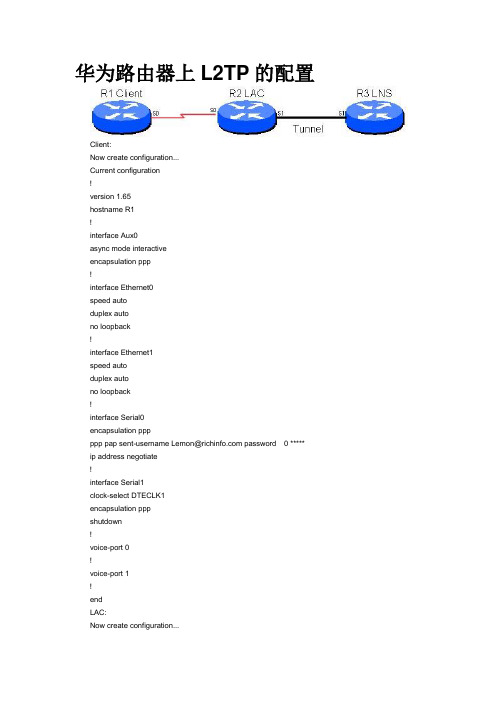
华为路由器上L2TP的配置Client:Now create configuration...Current configuration!version 1.65hostname R1!interface Aux0async mode interactiveencapsulation ppp!interface Ethernet0speed autoduplex autono loopback!interface Ethernet1speed autoduplex autono loopback!interface Serial0encapsulation pppppp pap sent-username Lemon@ password0 ***** ip address negotiate!interface Serial1clock-select DTECLK1encapsulation pppshutdown!voice-port 0!voice-port 1!endLAC:Now create configuration...Current configuration!version 1.65user Lemon@ service-type ppp password 0 ***** vpdn enableaaa-enableaaa authentication ppp default localaaa authentication login default localaaa accounting optionalhostname R2!interface Aux0async mode interactiveencapsulation ppp!interface Ethernet0speed autoduplex autono loopback!interface Ethernet1speed autoduplex autono loopback!interface Ethernet1speed autoduplex autono loopback!interface Serial0clock-select DTECLK1encapsulation pppppp authentication pap!interface Serial1encapsulation pppip address 202.103.1.21 255.255.255.252!vpdn-group 1request dialin l2tp ip 202.103.1.22 fullusername *****l2tp tunnel password 0 ****!endLNS:Now create configuration...Current configuration!version 1.65user Lemon@ service-type ppp password 0 ***** vpdn enableip local pool 1 192.168.1.2 192.168.1.254aaa-enableaaa authentication ppp default localaaa authentication login default localaaa accounting optionalhostname R3!interface Aux0async mode interactiveencapsulation ppp!interface Ethernet0speed autoduplex autono loopback!interface Serial0no loopback!interface Serial0encapsulation pppshutdown!interface Serial1clock-select DTECLK1encapsulation pppip address 202.103.1.22 255.255.255.252!interface Virtual-Template1encapsulation pppppp authentication pappeer default ip address pool 1ip address 192.168.1.1 255.255.255.0!vpdn-group 1accept dialin l2tp virtual-template 1 remote R2l2tp tunnel password 0 **** !end华为路由器配置VPN(2008-07-14 03:34:11)标签:l2tp vpn it分类:华为技术华为路由器配置VPN环境:路由器A公网IP:202.101.1.2/24Tunnel IP:192.168.0.1/30Source IP:202.101.1.2Destnation IP:202.101.2.2路由器B公网IP:202.101.2.2/24Tunnel IP192.168.0.2/30Source IP202.101.2.2Destnation IP202.101.1.2命令配置:命令版本 V3.40Router A#sysname RTA#interface Ethernet2/0ip address 202.101.1.2 255.255.255.0 /公网IP/#interface Ethernet2/1ip address 192.168.1.1 255.255.255.0 /内部私网IP/#interface Tunnel0 /创建tunnel 0/ip address 192.168.0.1 255.255.255.252 /tunnel IP和对方tunnel IP在同一网段/source 202.101.1.2 /源地址/destination 202.101.2.2 /目的地址/#ip route-static 0.0.0.0 0.0.0.0 202.101.1.1 preference 60 /到公网的默认路由/ip route-static 192.168.2.0 255.255.255.0 Tunnel 0 preference 60 /通过tunnel 访问对方私网的路由/Router B#sysname RTB#interface Ethernet2/0ip address 202.101.2.2 255.255.255.0 /内部私网IP/#interface Tunnel0 /创建tunnel 0/ip address 192.168.0.2 255.255.255.252 /tunnel IP和对方tunnel IP在同一网段/source 202.101.2.2 /源地址/destination 202.101.1.2 /目的地址/#ip route-static 0.0.0.0 0.0.0.0 202.101.2.1 preference 60 /到公网的默认路由/ip route-static 192.168.1.0 255.255.255.0 Tunnel 0 preference 60 /通过tunnel 访问对方私网的路由/#return2.5.4 lac 作为客户端典型应用1. 组网需求lac 同时作为l2tp 客户端,与lns 建立常连接。
路由器L2TP设置(自发隧道模式)
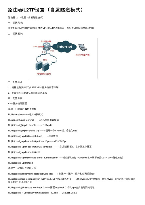
路由器L2TP设置(⾃发隧道模式)路由器 L2TP设置(⾃发隧道模式)⼀、组⽹需求:要求外⽹的VPN客户端使⽤L2TP VPN拨⼊RSR路由器,然后访问内⽹服务器和应⽤⼆、组⽹拓扑:三、配置要点:1、锐捷设备⽀持作为L2TP VPN 服务端和客户端2、配置VPN前要确认路由器上⽹正常四、配置步骤VPN服务端的配置步骤⼀:配置VPN相关参数Ruijie>enable ------>进⼊特权模式Ruijie#configure terminal ------>进⼊全局配置模式Ruijie(config)#vpdn enable ------>开启vpdnRuijie(config)#vpdn-group l2tp ------>创建⼀个VPDN组,命名为l2tpRuijie(config-vpdn)#accept-dialin ------>允许拨号Ruijie(config-vpdn-acc-in)#protocol l2tp ------>协议为l2tpRuijie(config-vpdn-acc-in)#virtual-template 1 ------>引⽤虚模板1,在步骤三中配置Ruijie(config-vpdn-acc-in)#exitRuijie(config-vpdn)#no l2tp tunnel authentication ------>隧道不加密(windows客户端不⽀持L2TP VPN隧道加密)Ruijie(config-vpdn)#exit步骤⼆:配置⽤户和地址池Ruijie(config)#username test password test ------>创建⼀个账户,⽤户和密码都是testRuijie(config)#ip local pool vpn 192.168.1.100 192.168.1.110 ------>创建vpn拨⼊的地址池,命名为vpn,给vpn客户端分配范围是192.168.1.100-110Ruijie(config)#interface loopback 0 ------>配置loopback 0 ,作为vpn客户端的⽹关地址Ruijie(config-if-Loopback 0)#ip address 192.168.1.1 255.255.255.0Ruijie(config-if-Loopback 0)#exit步骤三:配置虚拟模板Ruijie(config)#interface virtual-template 1 ------>创建虚模板1Ruijie(config-if)#ppp authentication chap ------>加密⽅式为chap Ruijie(config-if)#ip unnumbered loopback 0 ------>关联loopback 0 ,作为vpn 客户端的⽹关地址Ruijie(config-if)#peer default ip address pool vpn ------>引⽤地址范围,在步骤⼆中配置Ruijie(config-if)#ip nat inside ------>VPN客户端参与NAT步骤四:检查和保存配置Ruijie(config)#end ------>退出到特权模式Ruijie#write ------>确认配置正确,保存配置电脑客户端配置电脑作为L2TP VPN 客户端时需要修改注册表,参见附件或通过⽹络搜索。
H3C路由器L2TP配置详解

H3C路由器L2TP配置详解H3C路由器L2TP配置详解1:引言L2TP(Layer 2 Tunneling Protocol)是一种用于在公共互联网上建立虚拟私人网络(VPN)连接的协议。
本文将详细介绍如何在H3C路由器上配置L2TP协议。
2:确认硬件和软件要求在开始配置L2TP协议之前,请确保满足以下硬件和软件要求:- H3C路由器设备- 最新的H3C路由器操作系统- 有效的许可证3:步骤一、创建L2TP配置文件要创建L2TP配置文件,请按照以下步骤操作:- 连接到H3C路由器设备。
- 使用管理员权限登录。
- 打开路由器CLI(命令行界面)。
- 进入全局配置模式。
- 创建L2TP配置文件,并配置相关参数,如:隧道名称、IP 地址、预共享密钥等。
4:步骤二、配置L2TP隧道一旦L2TP配置文件创建成功,您需要完成以下步骤来配置L2TP隧道:- 进入隧道配置模式。
- 配置隧道类型和IP地址范围。
- 配置L2TP隧道的其他参数,如:数据压缩、最大会话数等。
5:步骤三、配置L2TP服务继续按照以下步骤配置L2TP服务:- 进入L2TP服务配置模式。
- 配置L2TP服务相关参数,如:监听端口、报文加密方式等。
- 配置L2TP客户端的IP地址池。
6:步骤四、配置用户认证为了确保只有经过身份验证的用户才能访问L2TP隧道,您需要配置用户认证。
请按照以下步骤操作:- 进入L2TP用户池配置模式。
- 配置用户认证相关参数,如:认证方式、用户名密码等。
7:步骤五、保存和应用配置完成以上步骤后,请保存并应用您的配置,使其生效。
示例如下:- 保存当前配置。
- 退出并应用配置。
8:附件本文档涉及以下附件:- 示例配置文件- L2TP隧道配置示意图9:法律名词及注释- L2TP(Layer 2 Tunneling Protocol):一种用于在公共互联网上建立虚拟私人网络(VPN)连接的协议。
- VPN(Virtual Private Network):通过使用公共互联网等非专用传输网络,在不同的网络之间建立安全的连接。
l2tpoveripsec(lns地址在内网,通过公网映射)
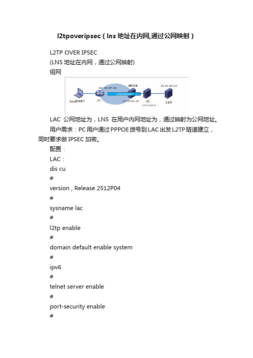
l2tpoveripsec(lns地址在内网,通过公网映射)L2TP OVER IPSEC(LNS地址在内网,通过公网映射)组网LAC公网地址为,LNS在用户内网地址为,通过映射为公网地址。
用户需求:PC用户通过PPPOE拨号到LAC出发L2TP隧道建立,同时要求做IPSEC加密。
配置:LAC:dis cu#version , Release 2512P04#sysname lac#l2tp enable#domain default enable system#ipv6#telnet server enable#port-security enable#password-recovery enable#acl number 3500rule 5 permit ip source 0 destination 0rule 10 permit ip source 0 destination 0#vlan 1#Ddomainauthentication ppp localaccess-limit disablestate activeidle-cut disableself-service-url disabledomain systemaccess-limit disablestate activeidle-cut disableself-service-url disable#ike peer lacexchange-mode aggressivepre-shared-key cipher $c$3$1x8s/6RGe2wayz2b/ilLMlHyJ86Kag==id-type nameremote-name lnsremote-address local-address local-name lacnat traversal#ipsec transform-set lacencapsulation-mode tunneltransform espesp authentication-algorithm sha1esp encryption-algorithm 3des#ipsec policy lac 1 isakmpsecurity acl 3500ike-peer lactransform-set lac#user-group systemgroup-attribute allow-guest#local-user adminpassword cipher $c$3$EiAlBrd/gVGFvSMRAmLoJwgze3wHlYa1BQ== authorization-attribute level 3service-type telnetservice-type weblocal-user testpassword cipher $c$3$SQ3SM2FRQoXeMijjRitI72ToSwbJ9f09xw== service-type pppl2tp-group 1tunnel password cipher $c$3$TVsHV3HQRBs5eubLlDPrKCp8o8kwnA== tunnel name lac start l2tp ip domain#interface Aux0async mode flowlink-protocol ppp#interface Cellular0/0async mode protocollink-protocol ppp#interface Virtual-T emplate1ppp authentication-mode pap chap domain#interface NULL0#interface Vlan-interface1pppoe-server bind Virtual-Template 1ip address GigabitEthernet0/0port link-mode routeip address ipsec policy lac#interface GigabitEthernet0/1port link-mode bridgeinterface GigabitEthernet0/2port link-mode bridge#interface GigabitEthernet0/3port link-mode bridge#interface GigabitEthernet0/4port link-mode bridge#ip route-static ip route-static dialer-rule 1 ip permit # load xml-configurationload tr069-configuration#user-interface tty 12user-interface aux 0user-interface vty 0 4authentication-mode scheme#returnLNS:#version Release 0202#sysname lns#telnet server enable#ip pool 1#password-recovery enable#vlan 1#interface Virtual-T emplate1ppp authentication-mode pap chap remote address pool 1 ip address NULL0#interface LoopBack0ip addressinterface GigabitEthernet1/0interface GigabitEthernet1/ description to-12/32 ip address vlan-type dot1q vid 1498 # interface GigabitEthernet2/0#interface GigabitEthernet2/description to-11/32ip address vlan-type dot1q vid 1499ipsec apply policy lns#scheduler logfile size 16#line class auxuser-role network-operator#line class consoleuser-role network-admin#line class vtyuser-role network-operator#line aux 0user-role network-operator#line con 0user-role network-admin#line vty 0 63authentication-mode schemeuser-role network-operatorip route-static 0 ip route-static 28 ip route-static 28authentication ppp local authorization ppp local accounting ppp local#domain system#aaa session-limit ftp 32aaa session-limit telnet 32aaa session-limit http 32aaa session-limit ssh 32aaa session-limit https 32 domain default enable system#role name level-0description Predefined level-0 role #role name level-1description Predefined level-1 role #role name level-2description Predefined level-2 role #role name level-3description Predefined level-3 role #role name level-4description Predefined level-4 role#role name level-5description Predefined level-5 role #role name level-6description Predefined level-6 role #role name level-7description Predefined level-7 role #role name level-8description Predefined level-8 role #role name level-9description Predefined level-9 role #role name level-10description Predefined level-10 role #role name level-11description Predefined level-11 role #role name level-12description Predefined level-12 role #role name level-13description Predefined level-13 role#role name level-14description Predefined level-14 role#user-group system#local-user admin class managepassword hash $h$6$rhjYlaMxTE8Yrgy/$pL4ngHJErR5IS6mIM2TVTpxVJoXAz3Z7 twS5WUoHnTBAVcnQ6zRTt3l/IV25NzoxYG4+xduBzNhiM+NovY5gUQ==service-type telnetauthorization-attribute user-role network-adminauthorization-attribute user-role network-operator#local-user test class managepassword hash $h$6$aeSFBsuE4NLmKV/p$Bmfz5WpYqTIdkrJhRl8v9xOkz2sxaxZ4Y0ZtkKglmyw3gvtamdEAxf0CItYelhqBRz/xZmmQF5DcZ3Y15oa5YA==service-type ftpservice-type telnetauthorization-attribute user-role network-operator#local-user test class networkpassword cipher $c$3$dxUAzslPK2voJ3xxO+kdUpqKQK52oAsuNQ== service-type pppauthorization-attribute user-role network-operator#ipsec transform-set lnsesp encryption-algorithm 3des-cbcesp authentication-algorithm sha1#ipsec policy-template lns 1transform-set lnsike-profile lns#ipsec policy lns 1 isakmp template lns#l2tp-group 1 mode lnsallow l2tp virtual-template 1 remote lactunnel name lnstunnel password cipher $c$3$TbJ0N3WspYQUVRSjjmPBxkFjo3Xhyg== #l2tp enable#ike identity fqdn lns#ike profile lnskeychain lacexchange-mode aggressivelocal-identity fqdn lnsmatch remote identity fqdn lacmatch local address GigabitEthernet2/#ike keychain lacpre-shared-key hostname lac key cipher $c$3$QGKCezjZ+NqQIHxyMuZsfR/weMCQAw== #return一:概述首先,先将这两个概念理顺一下。
L2TP的配置
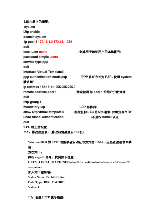
1.路由器上的配置:systeml2tp enabledomain systemip pool 1 172.16.1.2 172.16.1.254quitlocal-user usera /创建用于验证用户的本地帐号/ password simple useraservice-type pppquitinterface Virtual-Template0ppp authentication-mode pap /PPP认证方式为PAP,使用system 默认域/ip address 172.16.1.1 255.255.255.0remote address pool 1 /指定使用ip pool 1给用户分配地址/ quitl2tp-group 1mandatory-lcp /LCP再协商/allow l2tp virtual-template 0 /接受任何LAC的l2tp请求,并绑定到VT0/ undo tunnel authentication /不进行tunnel认证/quit2.PC机上的配置2.1:修改注册表:(修改后需要重启PC机)Windows2000的L2TP功能缺省启动证书方式的IPSEC,应当在注册表中禁用。
方法如下:执行regedit命令,找到如下位置HKEY_LOCAL_MACHINE\System\CurrentControlSet\Services\Rasman\P arameters加入如下注册项:Value Name: ProhibitIpSecData Type: REG_DWORDValue: 12.2:创建L2TP拨号链接:[RT1]dis cu[RT1]dis current-configuration#version 5.20, Alpha 1011#sysname RT1#password-control login-attempt 3 exceed lock-time 120 #l2tp enable#undo voice vlan mac-address 00e0-bb00-0000#ipsec cpu-backup enable#undo cryptoengine enable#domain default enable system#vlan 1#domain systemaccess-limit disablestate activeidle-cut disableself-service-url disableip pool 1 192.168.200.10 192.168.200.20#local-user l2tpuserservice-type ppppassword-control length 5local-user pppoeuserservice-type ppppassword-control length 5local-user pppuserservice-type ppppassword-control length 5#l2tp-group 1tunnel password simple 123tunnel name LACstart l2tp ip 23.1.1.2 fullusername l2tpuser#interface Ethernet0/1/0pppoe-server bind Virtual-Template 1 #interface Ethernet0/1/1port link-mode route#interface Serial0/2/0link-protocol pppppp authentication-mode chapppp chap user pppuser1ip address 12.1.1.1 255.255.255.0#interface Serial0/2/1link-protocol ppp#interface Virtual-Template1ppp authentication-mode pap remote address pool 1ip address 192.168.200.1 255.255.255.0 #interface NULL0#interface Ethernet0/4/0port link-mode bridge#interface Ethernet0/4/1port link-mode bridge#interface Ethernet0/4/2port link-mode bridge#interface Ethernet0/4/3port link-mode bridge#interface Ethernet0/4/4port link-mode bridge#interface Ethernet0/4/5port link-mode bridge#interface Ethernet0/4/6port link-mode bridge#interface Ethernet0/4/7#ip route-static 0.0.0.0 0.0.0.0 12.1.1.2#load xml-configuration#user-interface con 0idle-timeout 0 0user-interface vty 0 4#return[H3C]DIS CU[H3C]DIS current-configuration#version 5.20, Alpha 1011#sysname H3C#password-control login-attempt 3 exceed lock-time 120 #l2tp enable#undo voice vlan mac-address 00e0-bb00-0000#ipsec cpu-backup enable#undo cryptoengine enable#domain default enable system#ppp mp user pppuserb bind Virtual-Template 2 #vlan 1#domain systemaccess-limit disablestate activeidle-cut disableself-service-url disableip pool 1 192.168.100.2 192.168.100.3#local-user l2tpuserservice-type ppppassword-control length 5local-user pppuserbservice-type ppppassword-control length 5#l2tp-group 1mandatory-lcpallow l2tp virtual-template 1 remote LAC tunnel password simple 123tunnel name LNS#interface Ethernet0/1/0port link-mode route#interface Serial0/2/0link-protocol pppppp authentication-mode chapppp chap user pppusercppp mp#interface Serial0/2/1link-protocol pppppp authentication-mode chapppp chap user pppusercppp mp#interface Serial0/2/2link-protocol ppp#interface Serial0/2/3link-protocol ppp#interface Virtual-Template1ppp authentication-mode pap remote address pool 1ip address 192.168.100.1 255.255.255.0 #interface Virtual-Template2ppp mp binding-mode authentication ip address 23.1.1.2 255.255.255.0#interface NULL0#interface Ethernet0/4/0port link-mode bridge#interface Ethernet0/4/1port link-mode bridge#interface Ethernet0/4/2port link-mode bridge#interface Ethernet0/4/3port link-mode bridge#interface Ethernet0/4/4port link-mode bridge#interface Ethernet0/4/5port link-mode bridge#interface Ethernet0/4/6port link-mode bridge#interface Ethernet0/4/7port link-mode bridge#ip route-static 0.0.0.0 0.0.0.0 23.1.1.1 #load xml-configuration#user-interface con 0user-interface vty 0 4#return。
l2tp穿越nat实验
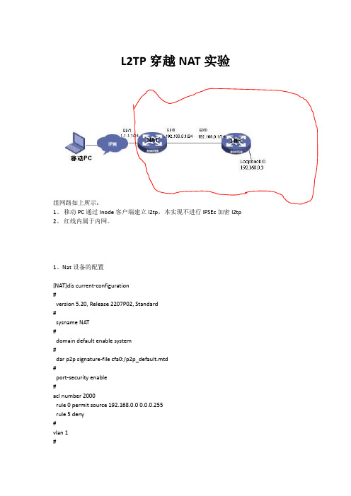
L2TP穿越NAT实验组网路如上所示:1、移动PC通过Inode客户端建立l2tp,本实现不进行IPSEc加密l2tp2、红线内属于内网。
1、Nat设备的配置[NAT]dis current-configuration#version 5.20, Release 2207P02, Standard#sysname NAT#domain default enable system#dar p2p signature-file cfa0:/p2p_default.mtd#port-security enable#acl number 2000rule 0 permit source 192.168.0.0 0.0.0.255rule 5 deny#vlan 1#domain systemaccess-limit disablestate activeidle-cut disableself-service-url disable#user-group systemgroup-attribute allow-guest#local-user adminpassword cipher .]@USE=B,53Q=^Q`MAF4<1!!authorization-attribute level 3service-type telnet#cwmpundo cwmp enable#interface Aux0async mode flowlink-protocol ppp#interface Cellular0/0async mode protocollink-protocol ppp#interface Ethernet0/0port link-mode routeip address 192.168.0.2 255.255.255.0#interface Ethernet0/1port link-mode routenat outbound 2000nat server 1 protocol udp global current-interface 1701 inside 192.168.0.3 1701 //因l2tp使用UDP 1701端口,所以需要将该端口映射。
windows自带的l2tp over ipsec配置参数
windows自带的l2tp over ipsec配置参数关于Windows自带的L2TP over IPsec配置参数Windows操作系统自带了一种名为L2TP over IPsec的VPN连接方式,该方式通过使用网络协议L2TP(Layer 2 Tunneling Protocol)和IPsec (Internet Protocol Security)来建立安全的虚拟私有网络(VPN),以增加网络传输的安全性和保密性。
在本文中,我们将一步一步地回答关于Windows自带的L2TP over IPsec的配置参数。
一、打开VPN连接设置:首先,打开Windows操作系统的“设置”菜单,点击“网络和Internet”选项,然后进入“VPN”部分。
二、创建新的VPN连接:点击“添加一个VPN连接”选项,然后在弹出的窗口中填入相关配置参数。
1. VPN提供商:请选择“Windows内建”选项,以使用Windows自带的VPN连接方式。
2. 连接名称:填入一个您喜欢的可以唯一标识该VPN连接的名称,例如“公司VPN”或“个人VPN”。
3. 服务器名称或地址:在此处填写VPN服务器的名称或IP地址。
您可以从VPN服务提供商或网络管理员那里获取这些信息。
4. VPN类型:请选择“使用L2TP/IPsec建立VPN连接”。
三、配置IPsec相关参数:点击“IPsec设置”选项,进入IPsec相关参数的设置页面。
1. 连接安全性:选择“需要加密”以确保连接的安全性。
2. 使用预共享密钥进行连接:选择“是”,并在“预共享密钥”文本框中填入与VPN服务器共享的预共享密钥。
预共享密钥是通过VPN提供商或网络管理员提供的安全口令,用于验证连接的身份。
3. 密码算法:选择您希望使用的加密算法。
Windows操作系统支持多种不同的算法,例如DES、3DES、AES等。
四、配置L2TP相关参数:点击“L2TP设置”选项,进入L2TP相关参数的设置页面。
L2TP和VPN接入方式介绍
这个场景适用于城域 网内部,各分支站点 访问总部资源,并且 不需要上公网的客户, 比如小企业分支等等, 可以采用WLAN与 GPON等专线结合的 方式。后面采用烟台 交运来举例
SSID:专用
R
BRAS VPN
移动城域网
农业银行专用VPN专 线
SR VPN
农业银行这个应用,
如果是各地市采用 VPN方式接入,但是 需要访问省行,就需 要与省行采用GRE方 式互联。如果是济南
IP报文头 (公网地址)
UDP 报文头
L2TP 报文头
PPP 报文头
IP报文头
Data
(私网地址)
• LNS收到报文后解封装时发现是L2TP报文,根据L2TP报 文头中的Tunnel ID和Session ID将其交给相应的进程处理
L2TP实现细节
数据封装与转发过程:
Dialer 10.2.2.2/24
L2TP实现细节
数据封装与转发过程:
Dialer 10.2.2.2/24
1.1.1.2/24 LAC
1.1.1.1/24
LNS 10.2.2.1/24
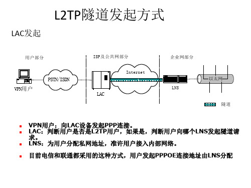
• 如上典型组网图中,Dialer为VPN用户,VPN用户发往 LNS的数据,首先发给LAC,格式如下图,可以看出此段 的数据是未经L2TP保护的
以太网报文头
BAS作为LAC的配置
• 看一个现网体彩的例子
• domain sdticai ---建立体彩的域,用户必须带域名上来 authentication-scheme none accounting-scheme none l2tp-group sdticai ---关联体彩的L2TP
l2tp-group sdticai -----配置体彩的l2tp LAC数据 tunnel password simple xxxxxxxx tunnel name sd-lac start l2tp ip-address 202.102.170.132 tunnel source LoopBack0
网件路由器怎么设置L2TP

网件路由器怎么设置L2TP全球领先的企业网络解决方案,及数字家庭网络应用倡导者美国网件公司,其出产的netgear网件路由器功能强大,那么你知道网件路由器怎么设置L2TP 吗?下面是店铺整理的一些关于网件路由器怎么设置L2TP 的相关资料,供你参考。
什么是L2TP?L2TP是一种工业标准的Internet隧道协议,功能大致和PPTP协议类似,比如同样可以对网络数据流进行加密。
不过也有不同之处,比如PPTP要求网络为IP网络,L2TP要求面向数据包的点对点连接;PPTP使用单一隧道,L2TP使用多隧道;L2TP提供包头压缩、隧道验证,而PPTP不支持。
在连接中要设置L2TP连接,方法同PPTP设置,同样是在连接属性窗口的“网络”选项卡中,将类型设置为“L2TP IPSec ”即可。
第二层隧道协议(L2TP)是用来整合多协议拨号服务至现有的因特网服务提供商点。
PPP 定义了多协议跨越第二层点对点链接的一个封装机制。
特别地,用户通过使用众多技术之一(如:拨号POTS、ISDN、ADSL 等)获得第二层连接到网络访问服务器(NAS),然后在此连接上运行 PPP。
在这样的配置中,第二层终端点和 PPP 会话终点处于相同的物理设备中(如:NAS)。
L2TP 扩展了 PPP 模型,允许第二层和 PPP 终点处于不同的由包交换网络相互连接的设备来。
通过L2TP,用户在第二层连接到一个访问集中器(如:调制解调器池、ADSL DSLAM 等),然后这个集中器将单独得的 PPP 帧隧道到 NAS。
这样,可以把 PPP 包的实际处理过程与 L2 连接的终点分离开来。
对于这样的分离,其明显的一个好处是,L2 连接可以在一个(本地)电路集中器上终止,然后通过共享网络如帧中继电路或英特网扩展逻辑 PPP 会话,而不用在 NAS 上终止。
从用户角度看,直接在 NAS 上终止 L2 连接与使用 L2TP 没有什么功能上的区别。
L2TP 协议也用来解决“多连接联选组分离”问题。
l2tp穿越nat实验

L2TP穿越NAT实验组网路如上所示:1、移动PC通过Inode客户端建立l2tp,本实现不进行IPSEc加密l2tp2、红线内属于内网。
1、Nat设备的配置[NAT]dis current-configuration#version 5.20, Release 2207P02, Standard#sysname NAT#domain default enable system#dar p2p signature-file cfa0:/p2p_default.mtd#port-security enable#acl number 2000rule 0 permit source 192.168.0.0 0.0.0.255rule 5 deny#vlan 1#domain systemaccess-limit disablestate activeidle-cut disableself-service-url disable#user-group systemgroup-attribute allow-guest#local-user adminpassword cipher .]@USE=B,53Q=^Q`MAF4<1!!authorization-attribute level 3service-type telnet#cwmpundo cwmp enable#interface Aux0async mode flowlink-protocol ppp#interface Cellular0/0async mode protocollink-protocol ppp#interface Ethernet0/0port link-mode routeip address 192.168.0.2 255.255.255.0#interface Ethernet0/1port link-mode routenat outbound 2000nat server 1 protocol udp global current-interface 1701 inside 192.168.0.3 1701 //因l2tp使用UDP 1701端口,所以需要将该端口映射。
使用L2TP VPN连接总部和分部.跨互联网的内网机器可以互相通信.从零开始配起!!

使用L2TP VPN连接总部和分部跨互联网的内网机器可以互相通信L2TP,即二层遂道协议,用来在IP网络建立加密遂道。
routeros可以做为L2TP的服务器,也可以做为L2TP的客户端。
公司总部路由器做L2TP服务器,公司分部接入路由器做L2TP客户端,两台路由器通过L2TP 连接后,两公司的内部的机器可以互相直接通信。
下面有一个布置实例。
先说一下网络拓扑结构。
总部路由器LAN侧网络使用私有地址10.1.1.254,WAN侧公网地址是201.1.1.1,总部路由器通过配置NAT使用LAN内部机器可以访问互联网。
分部中由器LAN侧网络使用私有地址192.168.1.254,WAN侧公网地址是202.1.1.4,分部路由器也通过配置NAT使用LAN内部机器可以访问互联网。
众所周知,此时,总部LAN内部机器是不可能直接和分部LAN内部机器直接通信。
因为各LAN内部机器用的是私有地址。
拓扑图如下:ISP----201.1.1.1 总部路由器10.1.1.254-----LAN交换机------ PC 192.168.1.1ISP----202.1.1.4 分部路由器182.168.1.254-----LAN交换机-------- PC 192.168.1.1经过L2TP VPN的配置,最终的目标是在两路由器之间建立L2TP会话,再通过静态路由,使用的两台处于内网的PC可以直接通信。
如下:ISP----201.1.1.1 总部路由器10.1.1.254-----LAN交换机------ PC 192.168.1.1|L2TP会话(总部端IP是172.16.1.1,分部端IP 是172.16.1.2)|ISP----202.1.1.4 分部路由器182.168.1.254-----LAN交换机-------- PC 192.168.1.1最终的路由效果如下:#总部内网机器到分部内网机器的路径,可以看到路径是走L2TP会话(172.16.1.1-172.16.1.2)的。
中国电信L2TP宽带认证客户端操作指引

L2TP认证客户端操作指引
1、在网管中心主页下载电信L2TP拨号客户端压缩包并解压。
2、双击运行HappyDialerSetup.exe,按安装向导提示安装软件。
完成安装后,
桌面将出现以下应用程序图标:
3、双击以上HappyDialer应用程序图标,打开软件界面。
点击菜单栏上的“网
络配置”,选择“新建”。
4、选择“新建”选项后,出现“网络连接配置”对话框,在“配置名称”
栏随意设置一个名称,如123。
接入方式选择L2TP。
然后点击“设置”
按钮。
5、点击“设置”按钮后,出现“接入方式设置”对话框。
在“宽带帐号”
和“宽带密码”栏填入在网络中心申请的宽带帐号和密码(如:帐号gzVPDNxxxxxx@gdcp211.v.gd 密码ABCDEFG )注意用户名和密码区分大小写。
6、完成帐号密码输入后,点击“导入以下配置按钮”,打开“文件选择对话
框”,选择下载本软件解压后的文件夹,选取“L2TP.txt”文件.
7、完成配置导入后结果如下:
点击确定。
8、完成以上配置,在“网络连接—配置”对话框点击“保存”
9、点击保存后返回应用程序主界面,在“网络连接”栏选择第4步在配置名
称栏设置的名称123。
点击“连接”
12、点击连接后客户端会自动进行L2TP拨号认证。
13、下线时,必须用鼠标右键点击右下角的连接图标,选择断开连接以正常下线。
- 1、下载文档前请自行甄别文档内容的完整性,平台不提供额外的编辑、内容补充、找答案等附加服务。
- 2、"仅部分预览"的文档,不可在线预览部分如存在完整性等问题,可反馈申请退款(可完整预览的文档不适用该条件!)。
- 3、如文档侵犯您的权益,请联系客服反馈,我们会尽快为您处理(人工客服工作时间:9:00-18:30)。
1用小凡模拟,R2,R3,R4用3640 R1,R5用3620
2 PC机一定要在虚拟机上做,而且拨号属性应把“证书”改为预共享密钥:gys198975
3 R3是公网路由,它上面有一还回口用来模拟公网地址
实验结果:
一:如果开启隧道分离(PC上设置,默认是不分离的),将可以访问公网但只能访问12.1.1.0网段。
15.1.1.0和1.1.1.0网段都不能访问,因为此时PC是无网关的只有IP地址
二:如果隧道不分离,PC不但可访问12.1.1.0,还可访问1.1.1.0和15.1.1.0,即系可以访问内网全部网段,因为此时PC机是有网关的,但隧道不分离就不能访问公网了
建议如果要访问公网就先断掉VPN连接,等访问完公网再连接VPN
HO R4
int e0/1
pppoe enable
pppoe-client dial-pool-number 1
nosh
int e0/0
ip add 192.168.1.1 255.255.255.0
ipnat inside
nosh
int dialer 1
ip address negotiated
encapsulationppp
ppp authentication chap callin
ppp chap hostname adsl
ppp chap pass gys198975
ipmtu 1492
dialer pool 1
ipnat outside
ipnat inside source list 101 interface dialer1 overload
access-list 101 permit ip any any
ip route 0.0.0.0 0.0.0.0 dialer1
********************************************************
ho R3
int e0/1
pppoe enable
nosh
int loopback 0
ip add 34.1.1.3 255.255.255.0
nosh
nosh
int e0/2
ip add 23.1.1.3 255.255.255.0
nosh
int lo3
ip add 3.3.3.3 255.255.255.0
nosh
vpdn enable
vpdn-grouppppoe_s
accept-dialin
protocolpppoe
bba-grouppppoe global
virtual-template 1
interface virtual-template 1
ip unnumbered loopback 0
encapsulationppp
ppp authentication chap
peer default ip address pool adsl-pool
exit
ip local pool adsl-pool 34.1.1.4 34.1.1.100
usernameadsl password gys198975
******************************************************************888 ho R2
vpdn enable
vpdn-group 1
accept-dialin
protocol l2tp
virtual-template 1
exit
no l2tp tunnel authen
usernamegys pass 0 gys198975
cryptoisakmp policy 1
encr 3des
hash md5
authen pre-share
group 2
exit
cryptoisakmp key 0 gys198975 address 0.0.0.0 0.0.0.0
cryptoipsec transform-set myset esp-3des esp-md5-hmac mode transport
exit
crypto dynamic-map dmap 1
set transform-set myset
exit
crypto map mymap 1 ipsec-isakmp dynamic dmap
int virtual-template 1
ip unnumbered e0/2
peer default ip add pool l2tp-pool
pppauthen chap ms-chap-v2
exit
ip local pool l2tp-pool 12.1.1.10 12.1.1.100
ip route 0.0.0.0 0.0.0.0 e0/2
int e0/2
ip add 23.1.1.2 255.255.255.0
crypto map mymap
ipnat outside
nosh
int e0/3
ip add 12.1.1.2 255.255.255.0
ipnat inside
nosh
access-list 111 permit ip any any
ipnat inside source list 111 interface e0/2 over
int lo2
ip add 2.2.2.2 255.255.255.0
nosh
exit
routerospf 110
router-id 2.2.2.2
net 12.1.1.0 0.0.0.255 area 0
net 2.2.2.2 0.0.0.255 area 0
*************************************************************** HO R1
int e0/3
ip add 12.1.1.1 255.255.255.0
nosh
exit
int e0/0
ip add 15.1.1.1 255.255.255.0
nosh
exit
int lo1
ip add 1.1.1.1 255.255.255.0
nosh
exit
routerospf 110
router-id 1.1.1.1
net 15.1.1.0 0.0.0.255 area 0
net 12.1.1.0 0.0.0.255 area 0
net 1.1.1.0 0.0.0.255 area 0。
