壁装 P10户外 6-3 Model (1)
户外P10单色LED模组电路图
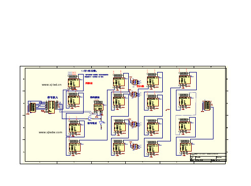
159-12行1列 1 2 3 4 5 6 7 9-12行8列 9
14 11 10 12 SCK 13 SER O0 O1 SRCLK O2 SRCLR O3 O4 RCLK O5 E O6 O7 Q7 SER O0 O1 SRCLK O2 SRCLR O3 O4 RCLK O5 E O6 O7 Q7
15 13-16行1列 1 2 3 4 5 6 7 9 GND VCC GND SER O0 O1 SRCLK O2 SRCLR O3 O4 RCLK O5 E O6 O7 Q7
U2 74HC595 U1 74HC595 U3 74HC595
2 GND
U4 74HC595 1 U2A
2
14 11 10 12 SCK 13
15 1 2 3 4 5 6 7 9
14 11 10 12 13 GND GND
SER O0 O1 SRCLK O2 SRCLR O3 O4 RCLK O5 E O6 O7 Q7
U14 74HC595 OE U?
15 1 2 3 4 5 6 7 9 GND Title P10单元板电路图
14 11 10 12 13 GND
15 1 2 3 4 5 6 7 9
14 11 10 12 SCK 13 GND
SER O0 O1 SRCLK O2 SRCLR O3 O4 RCLK O5 E O6 O7 Q7
U6 74HC595
15 5-8行9列 1 2 3 4 5 6 7 5-8行16列 9
14 11 10 12 SCK 13 GND VCC
6
A B
D
C
SER O0 O1 SRCLK O2 SRCLR O3 O4 RCLK O5 E O6 O7 Q7
P10P16P20户外全彩模组价格参数规格图片供应商
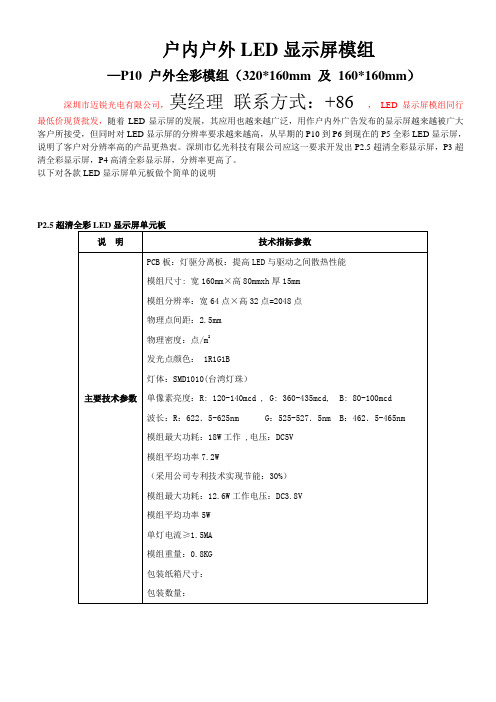
户内户外LED显示屏模组—P10 户外全彩模组(320*160mm 及160*160mm)深圳市迈锐光电有限公司,莫经理联系方式:+86 ,LED显示屏模组同行最低价现货批发,随着LED显示屏的发展,其应用也越来越广泛,用作户内外广告发布的显示屏越来越被广大客户所接受,但同时对LED显示屏的分辨率要求越来越高,从早期的P10到P6到现在的P5全彩LED显示屏,说明了客户对分辨率高的产品更热衷。
深圳市亿光科技有限公司应这一要求开发出P2.5超清全彩显示屏,P3超清全彩显示屏,P4高清全彩显示屏,分辨率更高了。
以下对各款LED显示屏单元板做个简单的说明P2.5超清全彩LED显示屏单元板说明技术指标参数主要技术参数PCB板:灯驱分离板:提高LED与驱动之间散热性能模组尺寸: 宽160mm×高80mmxh厚15mm模组分辨率:宽64点×高32点=2048点物理点间距:2.5mm物理密度:点/m2发光点颜色: 1R1G1B灯体:SMD1010(台湾灯珠)单像素亮度:R: 120-140mcd , G: 360-435mcd, B: 80-100mcd波长:R:622.5-625nm G:525-527.5nm B:462.5-465nm 模组最大功耗:18W工作 ,电压:DC5V模组平均功率7.2W(采用公司专利技术实现节能:30%)模组最大功耗:12.6W工作电压:DC3.8V模组平均功率5W单灯电流≥1.5MA模组重量:0.8KG包装纸箱尺寸:包装数量:主要技术参数1)驱动器件:采用台台湾聚积(5020)LED恒流驱动器件提高显示屏的刷新速度:≥3840帧/秒完美还原:4096级灰度图像:2)驱动方式:16/1驱动3)支持10(bit)位颜色:颜色数为1024X1024X1024=种颜色在播放高速运动视屏更加绚丽4)灰度:RGB各4096级5)白平衡亮度:≥1800cd/m266)亮度调节方式:软件调节255级可调7)平均无故障时间:≥6000小时8)半衰期寿命:≥7万小时9)平整度:任意相邻像素间≤0.18mm;模块拼接间隙<0.3mm ;10)有效通讯距离:网线100m,多模光纤500m,单模光纤50kmP3超清全彩LED显示屏单元板项目参数像素间距3mm最佳视距3-7.5m物理密度点/㎡显示亮度≥1200nite模组分辨率64点*32点LED封装SMD2020 1R1G1B驱动方式实像素1/16视角H:120°V:100°模组尺寸192mm*96mm*11mm模组功耗42W模组重量600g箱体尺寸384mm*384mm*131mm箱体分辨率128点*96点箱体重量11.5kg防护等级前/后:IP30刷新频率1000-4000Hz(取决于驱动芯片的不同而不同数值)光损耗在常温25℃使用30mA电流老化1000小时,LED亮度衰减小于5%平均无故障时间>5000小时杂点率<0.0001正常使用寿命>10万小时工作电压110V-240V AC±10%50-60Hz工作温湿度﹣30℃---﹢50℃/ 10%-90% RH存储温湿度﹣40℃---﹢60℃/ 10%-90% RH输入信号RF, S-VIDEO, RGBHV, YUN, YC & COMPOSITION, etc通信连接CA T5 Cable(Length≤1430m);Optical (Length≤20Km)Optional备注:以上参数仅作参考数据,可根据客户需求再做改动P4高清全彩LED显示屏单元板项目参数像素间距4mm最佳视距4-10m物理密度62500点/㎡显示亮度≥1500nite模组分辨率64点*32点LED封装SMD0606 1R1G1B驱动方式实像素1/8视角H:120°V:100°模组尺寸256mm*128mm*11mm模组功耗45W模组重量560g箱体尺寸576mm*576mm*131mm箱体分辨率144点*144点箱体重量11.5kg防护等级前/后:IP30刷新频率1000-4000Hz(取决于驱动芯片的不同而不同数值)光损耗在常温25℃使用30mA电流老化1000小时,LED亮度衰减小于5%平均无故障时间>5000小时杂点率<0.0001正常使用寿命>10万小时工作电压110V-240V AC±10%50-60Hz工作温湿度﹣30℃---﹢50℃/ 10%-90% RH存储温湿度﹣40℃---﹢60℃/ 10%-90% RH输入信号RF, S-VIDEO, RGBHV, YUN, YC & COMPOSITION, etc通信连接CA T5 Cable(Length≤1430m);Optical (Length≤20Km)Optional备注:以上参数仅作参考数据,可根据客户需求再做改动P5全彩LED显示屏单元板项目参数像素间距5mm最佳视距5-12.5m物理密度40000点/㎡显示亮度≥1800nite模组分辨率32点*32点LED封装SMD3528 1R1G1B驱动方式实像素1/8视角H:120°V:100°模组尺寸160mm*160mm*11mm模组功耗40W模组重量280g箱体尺寸640mm*640mm*131mm箱体分辨率128点*128点箱体重量13.6kg防护等级前/后:IP30刷新频率1000-4000Hz(取决于驱动芯片的不同而不同数值)光损耗在常温25℃使用30mA电流老化1000小时,LED亮度衰减小于5%平均无故障时间>5000小时杂点率<0.0001正常使用寿命>10万小时工作电压110V-240V AC±10%50-60Hz工作温湿度﹣30℃---﹢50℃/ 10%-90% RH存储温湿度﹣40℃---﹢60℃/ 10%-90% RH输入信号RF, S-VIDEO, RGBHV, YUN, YC & COMPOSITION, etc通信连接CA T5 Cable(Length≤1430m);Optical (Length≤20Km)Optional备注:以上参数仅作参考数据,可根据客户需求再做改动P6全彩LED显示屏单元板项目参数像素间距6mm最佳视距6-15m物理密度27777点/㎡显示亮度≥2000nite模组分辨率32点*16点LED封装SMD3528 1R1G1B驱动方式实像素1/8视角H:120°V:100°模组尺寸192mm*96mm*11mm模组功耗35W模组重量250g箱体尺寸576mm*576mm*11mm箱体分辨率96点*96点箱体重量10.6kg防护等级前/后:IP30刷新频率1000-4000Hz(取决于驱动芯片的不同而不同数值)光损耗在常温25℃使用30mA电流老化1000小时,LED亮度衰减小于5%平均无故障时间>5000小时杂点率<0.0001正常使用寿命>10万小时工作电压110V-240V AC±10%50-60Hz工作温湿度﹣30℃---﹢50℃/ 10%-90% RH存储温湿度﹣40℃---﹢60℃/ 10%-90% RH输入信号RF, S-VIDEO, RGBHV, YUN, YC & COMPOSITION, etc通信连接CA T5 Cable(Length≤1430m);Optical (Length≤20Km)Optional备注:以上参数仅作参考数据,可根据客户需求再做改动P7.62全彩LED显示屏单元板项目参数像素间距7.62mm最佳视距7.62-21m物理密度17222点/㎡显示亮度≥2200nite模组分辨率32点*16点LED封装SMD3528 1R1G1B驱动方式实像素1/8视角H:120°V:100°模组尺寸244mm*122mm*11mm模组功耗35W模组重量250g箱体尺寸976mm*976mm*131mm箱体分辨率128点*128点箱体重量24kg防护等级前/后:IP30刷新频率1000-4000Hz(取决于驱动芯片的不同而不同数值)光损耗在常温25℃使用30mA电流老化1000小时,LED亮度衰减小于5%平均无故障时间>5000小时杂点率<0.0001正常使用寿命>10万小时工作电压110V-240V AC±10%50-60Hz工作温湿度﹣30℃---﹢50℃/ 10%-90% RH存储温湿度﹣40℃---﹢60℃/ 10%-90% RH输入信号RF, S-VIDEO, RGBHV, YUN, YC & COMPOSITION, etc通信连接CA T5 Cable(Length≤1430m);Optical (Length≤20Km)Optional备注:以上参数仅作参考数据,可根据客户需求再做改动产品品质是企业生存的根本,以次充优,偷梁换柱是绝对没有发展的!。
P10高清户外全彩方案及技术参数

户外传媒LED显示屏工程方案目录第一部分 (3)1、显示屏通用技术特点 (4)2、公司显示屏工艺特点 (5)2.1材料控制工艺 (5)2.2模组控制工艺.............................. 错误!未定义书签。
2.3箱体结构设计工艺 (6)2.4屏体结构 (7)3、显示屏系统扩展技术优点综述 (8)3.1软件兼容性强 (8)3.2多种视频信号输入接口 (8)第二部分 (9)1、设计遵循原则 (10)2、设计指导思想 (10)3、软件设计说明 (11)3.1编辑/播放软件 (11)4、结构设计方案 (12)4.1材料选择 (12)4.2箱体结构 (12)4.3框架结构 (12)5显示屏功能描述 (13)5.1显示屏系统功能描述 (13)5.2户外适应性 (18)5.3防水处理 (19)5.4防尘处理 (19)5.5防晒 (19)5.6防潮 (20)5.7防冻 (20)5.8防眩处理 (20)5.9产品维护 (21)5.10产品维护 (21)5.11三级防雷技术 (21)5.12通讯接口 (22)第三部分 (24)产品相关报价 (29)第四部分 (28)4.1、品质定义 (28)质量保证体系 (29)4.2售后服务以及承诺 (30)1、品质承诺 (30)2、免费培训承诺 (30)基础培训 (31)现场培训 (31)3、售后服务承诺 (32)第一部分显示屏技术特点1、福建强力巨彩显示屏通用技术特点➢256级灰度控制技术单基色实现256级灰度,具有丰富的色彩、层次表现力。
➢非线性校正技术一种根据人眼对亮度级差敏感程度不同而做出的对LED显示屏亮度的修正技术。
➢Gamma 校正技术在控制电路采用一级Gamma校正技术。
➢静态恒流驱动以往显示屏由于技术水平以及设计及生产成本和空间的限制,全部是采用恒压驱动/动态扫描的驱动方式,这对于发光管的寿命和发光效率以及图文显示效果都是不利的。
随着行业技术水平的发展,驱动电路摒弃了动态恒压的驱动方式,采用静态恒流驱动方式,完美体现了LED的电流特性。
TF卡座规格大全
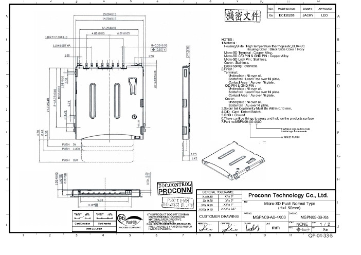
4/31!4/31!5/563/512/311/:61/222/1126/11MSPN09A REV.SHEET SCALE .X°± 2°X.°± 5°.XX°± 1°.XXX°± 0.5°.XXX± 0.10.XX± 0.20.X± 0.30X.± 0.40PROJ.UNIT APPROVAL CHECKED TITLE DRAWN DWG NO.B C D E F G H I I H G F ED AC B Proconn Technology Co., Ltd.J J PART NO.mmGENERAL TOLERANCE CUSTOMER DRAWING PROCESS COMPLIANT Pb -01-D GND WITHOUT CARD CARD INSERTED (#10)(#9) PATENTS PENDING. ARE COVERED BY PATENTS AND/OR 2.ALL RIGHTS RESERVED,PRODUCTS )TE!DBSE!DJSDVU!;(#9(#10)GND C/D 1.THIS PRODUCT DOESN'T CONTAIN ENVIRONMENTAL HAZARDOUS MATERIALS PER DIRECTIVE 2002/95/EC FOR RoHS.C/D Micro SD Normal push-push Type Connector 4:1D /21MSPN09-X0-0000D M B Dbse!Tmpu .B.1/96!2/21!2/:11/7122/261/211/16.1/16,B!!)23!;!2* A -- CONTACT UNLEAD PLATING: A:GOLD FLASH C:10ȝ" GOLD NOTES : 1. MATERIAL : INSULATOR : HIGH TEMPERATURE THERMOPLASTIC FLAMMABILITY RARING : UL94V-0 COLOR : BLACK CONTACT : COPPER ALLOYS COVER : COPPER ALLOYS 2. CONTACT AREA PLATING : GOLD OVER Ni C/D : MICRO SD CARD CARD DETECT INDICATION 3. P/N : MSPN09- X0-0000T A 1/4B C D D EN030807 BOB :/61:/:1y3!2/21!9/111/911/41QSPDPOO YYYYYYYEBUF!DPEFQSPDPOO!MPHP!!!!DBSE DFOUFS!MJOF 25/81.X°± 2°X.°± 5°.XX°± 1°.XXX°± 0.5°.XXX± 0.10.XX± 0.20.X± 0.30X.± 0.40UNIT APPROVAL CHECKED TITLE DRAWN Proconn Technology Co., Ltd.PART NO.GENERAL TOLERANCECUSTOMER DRAWING Micro SD Normal push-push MSPN09-X0-0000YYYYYYY YYYYYYYNOTES :1.Material :Housing/Slide : High temperature thermoplastic,UL94-V0. Housing Color : Black/Slide Color11.10 0.05NOTES :1.Material :Housing/Slide : High temperature thermoplastic,UL94-V0. Housing Color : Black/Slide Color11.10 0.05OPUFT!;!2/!NBUFSJBM!;!!!!!JOTVMBUPS!;!IJHI!UFNQFSBUVSF!UIFSNPQMBTUJD!!!!GMBNNBCJMJUZ!SBSJOH!;!VM:5W.1!DPMPS!;!CMBDLProconn Technology Co., Ltd.MICRO SD REV. PUSH-PUSH TYPE (H=1.8mm)DWG NO.MSPR09-15-BMICRO SD REV. PUSH-PUSH TYPE (H=1.8mm).X°± 2°X.°± 5°.XX°± 1°.XXX°± 0.5°TITLE Proconn Technology Co., Ltd.PART NO.GENERAL TOLERANCECUSTOMER DRAWING2/96²1/2²1/21/4²1/23/21.THIS PRODUCT DOESN'T CONTAIN ENVIRONMENTAL HAZARDOUSmm .nd hold on the products sur fa ce DWG NO.Proconn Technology Co., Ltd.1.THI S PRODUCT DOE S N'T CONT A M S PN10-09-0-4000D Push Nor ma l Type(H=1.50mm ).X °± 2°X .°± 5°.XX °± 1°.XXX °± 0.5°TITLEProconn Technology Co., Ltd.PART NO.L TOLER A NCETOMER DR A WING1.THI S PRODUCT DOE S N'T CONT A M SInput M a teri a l Direction1.THI S PRODUCT DOE S N'T CONT Arton P a per Connector Other bel P a perReel P S rrier T a pe P Sˠ˦˛ˡ˃ˋˀ˔˃ˀ˃˃˄ˆˠ˦˛ˡ˃ˋˀ˔˃ˀ˃˃˄ˆˠ˦˛ˡ˃ˋˀ˔˃ˀ˃˃˄ˆ。
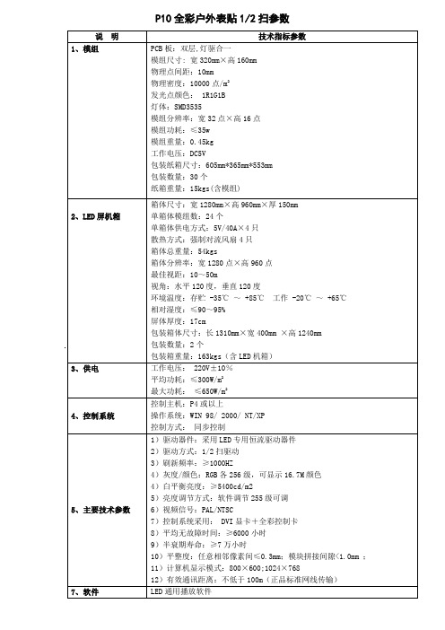
P10全彩户外模组参数
操作系统:WIN 98/ 2000/ NT/XP
控制方式:同步控制
5、主要技术参数
1)驱动器件:采用LED专用恒流驱动器件
2)驱动方式:1/2扫驱动
3)刷新频率:≥1000HZ
4)灰度/颜色:RGB各256级,可显示16.7M颜色
4)白平衡亮度:≥5400cd/m2
5)亮度调节方式:软件调节255级可调
环境温度:存贮-35℃~+85℃工作-20℃~+65℃
相对湿度:≤90~95%
屏体厚度:17cm
包装箱体尺寸:长1310mm×宽400mm×高1240mm
包装数量:2个
包装箱重量:163kgs(含LED机箱)
3、供电
工作电压:220V±10%
平均功耗:≤300W/m2
最大功耗:≤650W/m2
4、控制系统
6)视频信号:PAL/NTSC
7)控制系统采用:DVI显卡+全彩控制卡
8)平均无故障时间:≥6000小时
9)半衰期寿命:≥7万小时
10)平整度:任意相邻像素间≤0.3mm;模块拼接间隙<1.0mm;
11)计算机显示模式:800×600;1024×768
12)有效通讯距离:不低于100m(正品标准网线传输)
P10全彩户外表贴1/2扫参数
说明
技术指标参数
1、模组
PCB板:双层,灯驱合一
模组尺寸:宽320mm×高160mm
物理点间距:10mm
物理密度:10000点/m2
发光点颜色:1R1G1B
灯体:SMD3535
模组分辨率:宽32点×高16点
模组功耗:≤35w
模组重量:0.45kg
工作电压:DC5V
SPED1系列多位置开关说明书

94HorizontalType Vertical TypePower Push Slide RotaryEncoders Jog Shuttle Telephone -hook DetectorVibration Sensors Dual-in-line Package Type Multi Control Devices TACT4.5mm-travel Push Switch (Push-Push Type)SPED1 SeriesSwitches with a long travel of 4.5 mm are equipped with a connector terminal that can be installed without soldering.Typical SpecificationsItemsRating max. Resistive load 1A 14.5V DC 100m max.4.5 1N 30,000 cyclesContact resistance Operating forceOperating lifeSpecifications1Non shortingAlternateSPED110100Poles Changeover timingTerminal styleMinimum packing unit pcs. OperatingProducts No.Products LineRatingConnectorMountingmethodTravel mm 4.5Total travel mmFor other detailed specifications, see P.1004.5 mm-travel.Switching made available with push / push alternation movement.FeaturesFor switches of in-vehicle map lamps, game consoles, and other electronic devicesApplicationsCar Use95Horizontal Type Vertical TypePower PushSlideRotary EncodersJog Shuttle Telephone -hook Detector Vibration Sensors Dual-in-line Package TypeMulti Control Devices TACT12CCircuit Diagram (Viewed from the Direction A)8211.60.3(R 0.5)14±0.054±0.050 0.1DimensionsUnit : mmStyleReference dimension of connectiointerminal (T=0.4 to 0.6mm)Factory setting for contact points can be either 1or 2.Note4.5mm-travel Push Switch (Push-Push Type)SPED1 Series16.86.1ø11.15ø4.88ø9.7ø10 0.11417.24.5 0.56.75±0.29.51.28.8TravelTerminal No 1.Terminal No 2.Terminal No c .ø10 0.1APush Switch100Horizontal Type Vertical TypePower Push Slide Rotary Encoders Jog Shuttle Telephone -hook Detector Vibration Sensors Dual-in-line Package Type Multi Control Devices TACTProducts SpecificationsSPPJ3SeriesItemSPUJSPUPSPUN SPEC SPEA SPPJ2SPPJ6SPPH1SPPH2SPUNmedium currentSPPH4Operating temperature range0.1A 30VDC100M min. 500V DC 3N for 1 min.500V AC for 1 min.50N50N50N10 to 55 to 10Hz/min., the amplitude is 1.5mm for all the frequencies,in the 3 direction of X, Y and Z for 2 hours respectively230 5 3 0.5s300 10 3 1s 0350 103 1s0350 max.3s max.–20 2 for 96h85 2 for 96h40 2 ,90 to 95%RH for 96h10,000 cycles 40m max.10,000 cycles 40m max.10,000 cycles 40m max.10,000cycles 40m max.30,000 cycles 40m max.10,000 cycles 50m max.10,000cycles 50m max.10,000 cycles 50m max.10,000 cycles 40m max.10,000 cycles 100m max.10,000cycles 50m max.5,000cycles 40m max.10,000cycles 100m max.350 10 3 1s 0260 5 10 1s 260 max.5s max.260 5 5 1s260 5 10 1s260 5 5 1s 260 5 5 1s 260 5 10 1s 260 5 5 1s50N 50N30N30N10N5N for 1 min.20m max.20m max.30m max.30m max.100m max.0.2A30V DC0.2A 12V DC 0.1A 12V DC1A 25V DC 0.1A 30V DCSPED1SPED2SPED340˚C to 85˚C 10˚C to 60˚C3M min. 100V DC 100V AC for 1 min.230 5 3 0.5s–40 2 for 96h30,000 cycles 1 max.10,000 cycles 1 max. 350 10 3 0.5s260 510 1s100m max.1A 14.5V DC Rating max.Resistive loadElectricalperformanceMechanical performanceDurabilityEnvironmental performanceInitial contact resistance Insulation resistance Voltage proof Robustness ofterminalOperating directionPullingdirection Vibration SolderabilityOperating lifewithout loadOperating lifewith load Load : As ratingColdDry heat Damp heatDip soldering Manual soldering Resistance to soldering heat Robustnessof actuator 350 103 1s。
户外P10单红显示屏预算方案

驱动IC
恒流
最大功耗(KW)
300w/m²(启动功率×1.5倍)
平均功耗(KW)
180W/m²
总屏幕功耗(最大功耗)
13千瓦
平均寿命
>10万使用小时
最佳视距
大于10米
供压要求
220V50HZ±15%
外环境要求
-20℃-+60℃,30%-90%RH
2、系统报价(户外高清P10mm全彩LED显示屏系统价)
--
7
计算机
主留线开关
1台
1
用户自配
8
布线
提供
10
安装调试费
提供
11
运输费
包括
12
税金(普票8%)
另外收取
13
工程总价
RMB:26530元
1、LED显示屏报价(户外P10mm全彩)
屏体技术参数
屏体技术参数
户外钢架结构
型号
P10红色
像素
组 成
1R(红绿蓝)
点间距
10mm
单元模组
像素点数
32×16
尺寸(mm)
32厘米*18厘米
数 量
155张模块
屏体
宽高尺寸(mm)
9.92米*0.9米
像 素 数
864点×512点
防水方式
户外简易防水箱体
成品尺寸
10.2米*0.96米
平方
9.79
亮度(mcd/点)
≥6000cd/平方
发光管
光磊仕蓝二级发光
屏幕底色
黑色
点密度
1000ห้องสมุดไป่ตู้像素/m²
视角(度)
≥180°
P10全彩户外模组参数

控制主机:P4或以上
操作系统:WIN 98/ 2000/ NT/XP
控制方式: 同步控制
5、主要技术参数
1)驱动器件:采用LED专用恒流驱动器件
2)驱动方式:1/2扫驱动
3)刷新频率:≥1000HZ
4)灰度/颜色:RGB各256级,可显示颜色
4)白平衡亮度:≥5400cd/m2
5)亮度调节方式:软件调节255级可调
P10全彩户外表贴1/2扫参数
说 明
技术指标参数
1、模组
PCB板:双层,灯驱合一
模组尺寸: 宽320mm×高160mm
物理点间距:10mm
物理密度:10000点/m2
发光点颜色: 1R1G1B
灯体:SMD3535
模组分辨率:宽32点×高16点
模组寸:605mm*365mm*553mm
6)视频信号:PAL/NTSC
7)控制系统采用: DVI显卡+全彩控制卡
8)平均无故障时间:≥6000小时
9)半衰期寿命:≥7万小时
10)平整度:任意相邻像素间≤;模块拼接间隙< ;
11)计算机显示模式:800×600;1024×768
12)有效通讯距离:不低于100m(正品标准网线传输)
7、软件
LED通用播放软件
环境温度:存贮 -35℃ ~ +85℃ 工作 -20℃ ~ +65℃
相对湿度:≤90~95%
屏体厚度:17cm
包装箱体尺寸:长1310mm×宽400mm ×高1240mm
包装数量:2个
包装箱重量:163kgs(含LED机箱)
3、供电
工作电压: 220V±10%
平均功耗:≤300W/m2
最大功耗: ≤650W/m2
温室气环控制器说明书
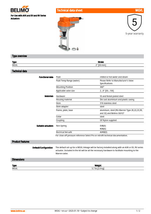
WGVLDefault/ConfigurationFor Use with AVK and EV and RV Series ActuatorsType overviewType Stroke WGVL2" [50 mm]Technical dataFunctional dataFluidchilled or hot water and steam Fluid Temp Range (water)Please Refer to Manufacturer's Valve Specifications Mounting Position 360°Applicable valve size2...6" [50...150]MaterialsHardware SS and Nickel plated steelHousing material Die cast aluminium and plastic casing Stem 316 stainless steel Stem adapter steelFrame, plate, base aluminum, steel (fits Warren Type 20,22,23,30, and 32) and Belimo G6/G7Collar steelCouplingGF Nylon supplied Suitable actuatorsNon-Spring EVB(X)RVB(X)Electrical fail-safeAVKB(X)For close-off pressure reference Select Pro or retrofit technical documentation.Product featuresThe default set up for a WGVL linkage will be factory installed along with an AVK or EV, RV series actuator. Included in the kit will be all the necessary hardware to facilitate mounting to the Warren valve.DimensionsType Weight WGVL5.7 lb [2.6 kg]WGVLEVB, EVX, RVB, RVXA B C D10.2" [260] 5.5" [140]9.2" [234]12.2" [310]AVKB, AVKXA B C D10.4" [264] 5.5" [140]10.3" [262]10.9" [276]AVKB120-3On/Off, Floating Point, Electrical Fail-Safe,Linear, 120 VTechnical dataElectrical dataNominal voltageAC 100...240 V Nominal voltage frequency 50/60 Hz Nominal voltage rangeAC 85...265 V Power consumption in operation 3.5 W Power consumption in rest position 2 W Transformer sizing 6.5 VAElectrical Connection18 GA appliance cable with 1/2" conduitconnector, 1 m, degree of protection NEMA 2 / IP54Overload Protection electronic throughout full stroke Electrical Protectionactuators are double insulated Functional dataActuating force motor 2000 N [450 lbf]Position feedback U note No Feedback Bridging time (PF)2 s Pre-charging time 5...20 sDirection of motion motor selectable with switch Direction of motion fail-safe reversible with switchManual override 5 mm hex crank (3/16" Allen), supplied Stroke1.25" [32 mm] Running Time (Motor)90 s /Running time motor note constant, independent of load Running time fail-safe <35 s Noise level, motor 60 dB(A)Noise level, fail-safe 60 dB(A)Position indicationMechanical, with pointer Safety dataPower source ULClass 2 Supply Degree of protection IEC/EN IP54Degree of protection NEMA/UL NEMA 2Enclosure UL Enclosure Type 2Agency ListingcULus acc. to UL60730-1A/-2-14, CAN/CSA E60730-1:02, CE acc. to 2014/30/EU and 2014/35/EU Quality Standard ISO 9001Ambient humidity Max. 95% RH, non-condensing Ambient temperature -22...122°F [-30...50°C]Storage temperature -40...176°F [-40...80°C]Servicingmaintenance-free Weight Weight6.39 lb [2.9 kg]MaterialsHousing materialDie cast aluminium and plastic casingAVKB120-3Footnotes† Use flexible metal conduit. Push the listed conduit fitting device over the actuator’s cable to butt against the enclosure. Screw in conduit connector. Jacket the actuators input wiring with listed flexible conduit. Properly terminate the conduit in a suitable junction box. Rated impulse Voltage 800V. Type of action 1. Control pollution degree 3.Electrical installationINSTALLATION NOTESActuators with appliance cables are numbered.Actuators may be connected in parallel. Power consumption and input impedance must beobserved.Meets cULus requirements without the need of an electrical ground connection.Warning! Live electrical components!During installation, testing, servicing and troubleshooting of this product, it may be necessary to work with live electrical components. Have a qualified licensed electrician or other individual who has been properly trained in handling live electrical components perform these tasks. Failure to follow all electrical safety precautions when exposed to live electrical components could result in death or serious injury.Wiring diagrams On/OffFloating Point。
室外P10全彩色LED显示屏设计施工方案

室外P10全彩色LED显示屏设计施工方案一、项目概述二、设计流程1.用户需求分析:与客户沟通了解其需求和要求,包括显示屏尺寸、安装位置、显示内容等。
2.技术参数确定:根据客户需求,确定P10全彩色LED显示屏的像素点密度、亮度、防护等级等技术参数。
3.结构设计:根据实际情况,设计LED显示屏的支架结构,并确定安装方式和固定方法。
4.电气连线设计:设计电气连线图,确定电源线路、信号线路和控制系统等的布置方案。
5.控制系统设计:选择合适的控制系统,确保显示屏可以按照要求顺利工作。
三、施工流程1.基础施工:根据显示屏尺寸和安装位置,打好基础,确保显示屏的稳固安装。
2.支架安装:根据设计方案,安装好显示屏的支架结构,并进行固定和调整。
3.模块安装:将LED显示屏的模块逐一安装到支架上,确保每个模块的位置和连接正确。
4.电气连线:根据设计图纸,连接电源线路、信号线路和控制系统等,确保电气连线正确无误。
5.调试测试:完成安装后,对LED显示屏进行调试测试,检查显示效果、亮度等是否符合要求。
6.安装调整:根据实际情况,对显示效果、亮度等进行调整,确保达到最佳效果。
7.防护措施:对显示屏进行防护,如加装防水罩、防晒罩等,确保其长期稳定运行。
四、注意事项1.施工前需充分了解客户需求,确保设计方案和施工流程符合其要求。
2.施工过程中,需严格遵守相关安全规范,确保施工人员和设备的安全。
3.在施工过程中,需密切配合供应商和客户,及时解决问题和沟通需求。
4.施工完成后,需进行全面的测试和调试,确保显示屏可以正常运行和使用。
5.在显示屏的后期维护中,需定期检查和清洁,确保其长期稳定运行和良好显示效果。
五、总结本方案提供了一套完整的室外P10全彩色LED显示屏设计和施工方案。
通过合理的设计和施工流程,可以确保显示屏的稳定安装和正常使用,满足客户的需求和要求。
同时,也需要注意施工过程中的安全和维护工作,以保证显示屏的长期稳定运行。
西部猴车(湘潭)电控发货图纸 Model (1)

ib-20 ib-21
D2 端子注释
N
L 端子号
3
127V
2
1
127V
D1 端子注释
AC127V电源
去KXJ-1/127矿用隔爆兼本安PLC控制箱ib1
4
23-5 23-4 8-5 8-4
端子号 4-3 4-2 4-1 CAN-L CAN-H
VSS ibGND1 4
设置 3
VSS ibGND1 2
1
VCC1 5V
端子注释
2 23-8
IN2
14-2
OUT103 1
15-2 OUT102
2
11-6 OUT101 3
OUT93 4
1 OUT121
2
16-2
OUT122
3 OUT123
11-8
4 OUT111
2
HXD-CK3 CAN开关量输入模块
5
HXD-YT-4
语言信号通讯模块
9
二极管电路板
13 远程呼叫
14 打点
15-2 16-2
14-2 OUT92
5
11-4 OUT91 6
18-2 OUT83
7
5 OUT112 6 OUT113
IN12
7 IN12
1
2 3
IN6 12 IN6
IN5 11 IN5
IN4 10 IN4
IN3 9 IN3
IN2 8 IN2
3 IN9 4 IN10 5 IN11 6 IN12 7 IN1
IN8 2 IN8
11-72 11-82 2-L7/ib-15 2-L8/ib-16 11-92 11-103
矩阵输入Y1 15 ib-11
3.9兴文凤麟广告
180
180
数据转接线3米
1条
10
10
16P排线长50cm
4条
3
12
背条1*4*10.675米/支
26支
6
156
背条1*2*1 0.675米/支
4
4.5
18
铝合金边框45*90
18.6米
20
371
45*90拐角
4个
3
12
合计
8037
5V电源线(标准)
赠送
16P短排线
赠送
P10全户外单红板,27张长*4张高整屏尺寸:8.73米*0.73米=6.37平方
9.92米
20
198
45*90拐角
4个
3
12
合计
3284
5V电源线(标准)
赠送
16P短排线
赠送
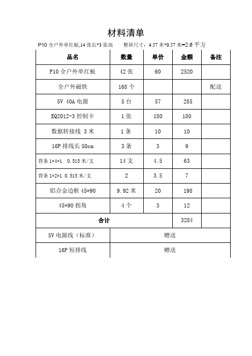
P10全户外单红板,14张长*3张高整屏尺寸:4.57米*0.57米=2.6平方
材料清单
品名
数量
单价
金额
备注
P10全户外单红板
108张
60
6480
全户外磁铁
432个
配送
5V40A电源
14台
57
798
EQ2012-3控制卡
材料清单
品名
数量
单价
金额
备注
P10全户外单红板
42张
60
2520
全户外磁铁
168个
配送
5V40A电源
5台
57
285
EQ2012-3控制卡
1张
180
180
数据转接线3米
1条
10
19
Carter Ground Fueling Model 64031 3英寸双性接口应用说明说明书
Model 640313" Unisex CouplingA pplicable additional manuals :NONESM 64031May 2007Maintenance & Repair ManualAerospace GroupConveyance Systems DivisionCarter ® Brand Ground Fueling EquipmentTABLE OF CONTENTSPAGE (3)1.0 INTRODUCTIONDESCRIPTION (3)2.0 EQUIPMENT3.0 TABLE OF OPTIONS AND ORDERING INFORMATION (3)4.0 DISASSEMBLY (3)5.0 INSPECTION (4)6.0 REASSEMBLY (4)7.0 TEST (5)8.0 ILLUSTRATED PARTS CATALOG (6)MAINTENANCE, OVERHAUL & TEST INSTRUCTIONSCARTER PART NUMBER 64031 UNISEX COUPLING 1.0 INTRODUCTIONThis manual furnishes detailed instructions covering the maintenance and overhaul of Carter Ground Fueling Model Number 64031, 3" Unisex Couplings and the various options listed in Section 3.0.2.0 EQUIPMENT DESCRIPTIONCarter Model 64031 Valved Unisex Coupling is a 3 inch hose coupling that is universally connectable to other 64031 Valved Unisex Couplings. The units are qualified in accordance with A-A 59377, Class A which supercedes MIL-C-53071. Section 3.0 details the various options available. Other configurations of Carter units that are available and to which the 64031 will mate are listed in Section 3.0. The basic valved coupling would be procured under the part number 64031 with various options that determine the desired inlet or hose mounting configuration. The exploded views in the figures at the end of the manual include the various options available. Item numbers referenced in Sections 4 through 7 refer to the parts list in Table 1.3.0 TABLE OF OPTIONS AND ORDERING INFORMATIONThe 64031 is available with various inlet or hose mounting configurations as described in the tables below. The units are available in two colors to meet the customers requirements, tan (standard) and green (option V).DESCRIPTION OPTION LETTER DESCRIPTION OPTION LETTERC Adds 100 Mesh Screen N Adds 1-1/2" Male NPT inletD Adds 3" Hose Barb Inlet P Adds 4" Male Camlock InletE Adds 4" Hose Barb Inlet Q Adds Dust Cap/Plugs, Camlock TypeF Adds 2" Male Camlock Inlet R Adds 3" Female NPT InletG Adds 2" Female Camlock Inlet S Adds 3" Male NPT InletH Adds D-1/D-2 Inlet Flange T Adds 3" MS33786-48 Flanged InletJ Adds 2" Male NPT Inlet U Adds 3" Vitaulic Grooved End Inlet K Adds 3" Female Camlock Inlet V Changes exterior color to greenL Adds 2” Hose Barb Inlet W Adds 4" Male BSPP InletM Adds 4" Female Camlock Inlet Z CRES Interface Locking Lugs Note: One of the above options letters must be included with the basic part number 64031 to receivea completed unit.Example: 64031D - 3" Unisex Coupling with 3" Hose Barb Inlet Fitting.64031KQ – 3” Unisex Coupling with 3” Female Camlock Inlet and Dust Plug.4.0 DISASSEMBLY4.1 Remove Screw (1) using a torque wrench,checking the running torque. If the runningtorque is less than 9.5 in lbs (0.11 m kg),discard the Screw (1). Note: Screw (1) isself-locking and is designed to be reused upto 15 times before replacement is necessary. If a torque wrench is not used to remove it, Screw (1) should be replaced. Remove and discard Packing (2). Holding the unit over a suitable container to collect the Balls (3) in the swivel joint, with the screw hole toward the container, rotate theinlet fitting to allow the Balls (3) to fall intothe container. There should be 41 Balls (3).When all 41 Balls (3) have been collected,remove the inlet adapter (ref. Figure 2 forvarious inlet types). Note there is a smallspring loaded Ball (4) and Spring (5) thatare used to maintain electrical continuity.This ball and spring are located on theadapter. As the adapter is removed the ballwill become exposed and be pushed out bythe spring and may be lost in the removalprocess. Remove and discard Packing (6). 4.2 Rotate handle 8 to the open position.Remove Screws (7) and Handle Assembly(8). It is not necessary to disassembleHandle Assembly (8) unless it is damagedand in need of repair. Set the HandleAssembly (8) aside for later use.If necessary to disassemble HandleAssembly (8), use an Allen Key to removeScrew (9) and Spring (10).4.3 Using an Allen Key, remove Screw (13),turn unit over and remove the secondScrew (13) from the opposite end. Usingone of the Screws (7) in the Shaft (14) as aremoval tool, remove Shaft (14). Removeand discard Packings (15) and (16) andBushing (17). Remove and discard Bushing(18).4.4 Reaching in the inlet end, remove Ball (19)from the unit. Push out the Lower Shaft(20). Remove and discard Packings (15)and (16) and Bushing (17).Remove Seal Wire (22) from inside ofHousing (21). Remove Seal Retainer (23)and Seal (24). Discard Seal (24).4.5 Remove the Bumper (25) only ifreplacement is needed or if it is necessaryto replace Lugs (26) or (27). If necessary,remove Screws (28) from Lugs (26) or(27).4.7 Do not remove Spring Pin (29) that retainsthe Lockout Pin (30) unless it is necessaryto replace any of these parts. If necessary,using a drift pin, press out Spring Pin (29)and discard it. This will allow the removalof Lockout Pin (30) and Spring (31).4.8 Remove Seal (32) from unit and discard.4.9 Do not try to disassemble the Housing (21)to remove the spring loaded Ball (33) orRetainer (34) permanently affixed in theface of the unit. If the ball is damaged,replacement of the Housing (21) will benecessary.4.10 Peel out and discart Seal (32) from theDust Cap (36). Note: do not remove centerplug from dust cap. It is a pressed fit andnever needs replacing. If the obsoletemetal Dust Cap Assy (36A) is present andneeds replairing, it is recommended that itbe replaced with the newer plastic cap(36).5.0 INSPECTIONIt is recommended that all Packings (2), (6), (15) & (16), Seals (24) and (32) and Bushings (17) and (18) be discarded and replaced at each overhaul.Inspect all metal parts for dings, gouges, abrasions, etc. On all parts except for the Ball (19), use 320 grit paper to smooth and remove sharp edges. Replace any part with damage exceeding 15% of local wall thickness. Use alodine 1200 to touch up bared aluminum. If Ball (19) is scratched or damaged it should be replaced.Inspect the Bumper (25) for evidence of cracking or wear. Replace as necessary. Check Lugs (26) and (27) to assure that they are not loose. If loose, remove Bumper (25) to check the tightness of the Screws (28). Screws should be tightened to 6 in-lb. Count the Balls (3) to make sure that all 41 are present.Check the ball groove (round bottom) of the inlet swivel. If groove is worn such that burrs exist, use 320 grit paper to smooth and remove sharp edges. Burrs will make it difficult to re-install the part.Inspect the small spring loaded ball located in the face of the unit. Push the ball in and be sure that it pops back into place. The purpose of this ball is to provide electrical continuity between mating units.Inspect Screw (9) and Handle (11) for damage that could have been caused by dropping the unit. If either part is bent replace it.Inspect Dust Cap Assy (36) to make sure that the center portion that is pressed in place remains in place. If it is missing, theSeal (32) will also be missing, in whichevent it will be necessary to replace theCap Assy..6.0 REASSEMBLYReassemble the parts in the reverseorder of disassembly noting thefollowing:6.1 Make certain all components are cleanand free from oil, grease, or any othercorrosion resistant compound on all interior or exterior surfaces. Wash allparts with cleaning solvent, Federal Specification P-D-680 or equivalent, anddry thoroughly with a clean, lint-free clothor compressed air.WARNING!Use cleaning solvent in a well-ventilated area. Avoid breathing of fumes and excessive solvent contact with skin. Keep away from open flame.NOTE: A light coat of petrolatum, FederalSpecification VV-P-236 or equivalent commercial quality, can be applied to all o-rings and seals for ease of installation. A thin coating should also be applied to the Ball(19).6.2 When installing Seal (32) into DustCap (36) use a finger to be sure thatthe seal is properly seated in itsgroove. The same procedure shouldbe used when installing the same Seal(32) into the groove in the Housing(21). These seals are identical andcan be interchanged.6.3 If the Lockout Pin (30) and Spring (31)were removed, it will be necessary toreinstall them using a drift pin to installSpring Pin (29) into Housing (21).Note that the rounded portion of theLockout Pin (30) is positioned towardthe outer diameter of the Housing (21).6.4 If the Lugs (26) and (27) were removed, installthem in their proper positions. Align the holesin the Lugs (26) or (27) with the hole pattern inthe Housing (21). Tighten Screws (28) to 15in-lb.6.5 Re-install Bumper (25) onto Housing (21) suchthat the thin lip seal end is facing away fromthe unit.6.6 Place Seal (24) into Housing (21) with the flatsurface inserted into the Housing (21). InsertSeal Retainer (23) and reinstall Seal Wire (22)into the groove to retain.6.7 Insert Ball (19) into Housing (21). PlaceBushings (17) onto Lower Shaft (20) along withPacking (15). Place Packing (16) into groovein Lower Shaft (20) and insert into Housing (21)and Ball (19) aligning the flats of the two parts,retaining with Screw (13).6.8 Install Bushing (18) into the groove in theHousing (21). Place Bushing (17) onto UpperShaft (14) along with Packing (15). PlacePacking (16) into groove in Upper Shaft andinsert into Housing (21) and Ball (19) aligningthe flats of the two parts. Retain with Screw(13).6.9 If Handle Assembly (8) was disassembledearlier, reinstall Spring (10) and Screw (9) intoHandle (11) and bottom out into Knob (12).Handle Assembly (8) can then be assembledusing the two Screws (7).6.10 Place Packing (6) onto Inlet [ref. Fig. 2, items(1) thru (20)] and start the Inlet into the openingin the Housing (21). Install Spring (5) and Ball(4) into hole in Inlet, and holding it in thecompressed position, finish installing the Inletinto Housing (21). Insert the 41 Balls (3) intothe hole in the Housing (21) by rotating the Inletwhile installing the Balls (3). Once all 41 Balls(3) are installed, place Packing (2) onto Screw(1) and install the assembly into the threadedholes to retain the joint. Torque to 76 ± 4 in-lb.7.0 TEST7.1 The following test procedures will beaccomplished after overhaul:7.2 Test conditionsTest media shall be JP-8 MIL-T-83133, JetA, odorless kerosene or Stoddard typesolvent MIL-PRF-7024E Type II.7.3 Functional Test7.3.1 Using the test unit and a similar valvedunisex coupling, make sure that they willconnect correctly while both couplings arein closed condition. After connecting thecouplings, open the test unit and try todisconnect by applying a counterclockwisemotion. The coupling, in open position, willprevent any disconnect attempt. Thenclose the test unit and disconnect byapplying a counter-clockwise motion.7.3.2 Connect the test unit to another unisexcoupling with inlet capped. Connect fluidpressure source capable of 100 psipressure to the inlet of the test unit. Withthe Handle Assembly (8) in the openposition, apply pressure of 5 and 100 psigto the system and observe for externalleakage. There should be no leakage overa period of at least one minute. Reduce thesystem pressure.7.3.3 C onnect fluid pressure source capable of100 psi pressure to the inlet of test unit.With the test unit in disconnected conditionand the Handle Assembly (8) in the closedposition, apply pressure of 5 and 100 psigto the system and observe for externalleakage. There should be no leakage overa period of at least one minute. Reduce thesystem pressure.7.3.4 Remove test unit from the test system andinstall the dust cap.8.0 ILLUSTRATED PARTS CATALOGTable 1.0 tabulates the parts and sub-assemblies comprising the 64031 Unisex Coupling. The item numbers of the table are keyed to the exploded views of the nozzle diagrammed in Figures 1 and 2.TABLE 1.0 Refer. To Figure 1Item PartNumber Description Units PerAssemblyCouplingOptionUnits/YrSpares/101 220484 Screw...............................................1 All -2 MS29512-03 Packing............................................1 All 103 82123 Ball ...............................................41 All -4 220265 Ball .................................................1 All 55 220153 Spring...............................................1 All 56 MS29513-234 Packing............................................1 All 107 PL24693C50 Screw...............................................2 All -8 47119 HandleAssembly.............................1 All -9 220204 Screw.......................................1 All -10 220145 Spring.......................................1 All -11 220435 Handle......................................1 All -12 220142 Knob.........................................1 All -13 GF16997-32L Screw...............................................2 All -14 220430 Shaft, Upper.....................................1 All -15 MS29513-016 Packing............................................2 All 2016 MS29513-009 Packing............................................2 All 2017 220464 Bushing............................................3 All 3018 220466 Bushing............................................1 All 1019 220449 Ball .................................................1 All -20 220432 Shaft, Lower.....................................1 All -21 220429-1 Housing, Tan...................................1 Allbut V -220429-2 Housing, Green................................1 V-22 220470 Wire, Seal........................................1 All -23 220459 Retainer, Seal..................................1 All -24 220465 Seal .................................................1 All -SM64031 May 2007Item PartNumber Description Units PerAssemblyCouplingOptionUnits/YrSpares/1025 220468 Bumper............................................1 All -26 220446-1 Lug, Long (aluminum)......................1 All but Z, ZV -220800-1 Lug, Long (CRES)...........................1 Z,ZV27 220446-2 Lug, Short (aluminum).....................1 All but Z, ZV -220800-2 Lug, Long (CRES)...........................1 Z,ZV28 GF16997-20L Screw...............................................4 All -29 .094x1.000LDP Pin, Spring.......................................1 All -30 220457 Pin, Lockout.....................................1 All -31 LC030D-8 Spring ............................................. 1 All-32 220467 Seal ............................................. 1 All 1033 220265 Ball ............................................. 1 All -34 220334 Retainer ........................................... 1 All-35 220153 Spring ............................................. 1All- -36 47395 Cap Assy ......................................... 1All-37 28-2-G Sleeve................................... 2 All -38 82499-2000 Cable..................................... 1 All -39 220482 Ring....................................... 1 All-36A 47121-1 Cap Assy, Tan (on older units)......... - All but V -47121-2 Cap Assy, Green (on older units)..... - V -- KD64031-1 Kit of seals for 64031 (any option except G, K & M; use kits -2 thru -4for these options) with single coupling - contains items2,6,7,13,15,16,17,18,24,28,32.- KD64031-2 Kit of seals for 64031JG or JGV only - contains items 2, 6, 7, 13, 15,16, 17, 18, 24, 28, 32, 13A- KD64031-3 Kit of seals for 64031KS only - contains items 2, 6, 7, 13, 15, 16, 17,18, 24, 28, 32, 15A.- KD64031-4 Kit of seals for 64031MS only - contains items 2, 6, 7, 13, 15, 16, 17,18, 24, 28, 32 14A.SM64031 May 2007 TABLE 2.0Refer to Figure 2Item PartNumber Description Units PerAssemblyCouplingOptionUnits/YrSpares/101 221498-1 Inlet, 2” Hose Barb, Tan.............................1 L -221498-2 Inlet, 2” Hose Barb, Green.........................1 LV -2 220381-1 Inlet, 3" Hose Barb, Tan.............................1 D -220381-2 Inlet, 3" Hose Barb, Green.........................1 DV -3 221085-1 Inlet, 4” Hose Barb, Tan.............................1 E -221085-2 Inlet, 4” Hose Barb, Green.........................1 EV -4 220503-1 Inlet, 3" MS33786-48 Flange, Tan.............1 T -220503-2 Inlet, 3" MS33786-48 Flange, Green.........1 TV -5 220510-1 Inlet, 3" Victaulic Groove, Tan...................1 U -220510-2 Inlet, 3" Victaulic Groove, Green................1 UV -6 47305-1 Inlet,D-2/D-2 Flange, Tan.........................1 H - 47305-2 Inlet,D-2/D-2Flange, Green.....................1 HV -7 221183-1 Inlet, 1-1/2” Male NPT, Tan.......................1 N -221183-2 Inlet, 1-1/2” Male NPT, Green....................1 NV -8 220384-1 Inlet, 2" Male NPT, Tan..............................1 J -220384-2 Inlet, 2" Male NPT, Green..........................1 JV -9 220455-1 Inlet, 3" Male NPT, Tan..............................1 S -220455-2 Inlet, 3" Male NPT, Green..........................1 SV -10 221243-1 Inlet, 4” Male BSPP, Tan...........................1 W -221243-2 Inlet, 4” Male BSPP, Green.......................1 WV -11 221084-1 Inlet, 3” Female NPT, Tan.........................1 R -221084-2 Inlet, 3” Female NPT, Green......................1 RV -12 220382-1 Inlet, 2" Male Camlock, Tan.......................1 F -220382-2 Inlet, 2" Male Camlock, Green...................1 FV -13 220383-1 Inlet, 3" Male Camlock, Tan.......................1 P -220383-2 Inlet, 3" Male Camlock, Green...................1 PV -14 20DAL-TN Inlet, 2" Female Camlock, Tan...................1 G -20DAL-GN Inlet, 2" Female Camlock, Green...............1 GV -14A MS27030-6 Gasket............................................1 G,GV 1015 30DAL-TN Inlet, 3" Female Camlock, Tan...................1 K -30DAL-GN Inlet, 3" Female Camlock, Green...............1 KV -15A MS27030-8 Gasket............................................1 K, KV 1016 4030DAL-TN Inlet, 4" Female Camlock, Tan...................1 M -4030DAL-GN Inlet, 4" Female Camlock, Green...............1 MV -16A MS27030-9 Gasket............................................1 M,MV 1017 GF27028-11-TN Dust Cap, 2” Female Camlock, Tan..........1 FQ -GF27028-11-GN Dust Cap, 2” Female Camlock, Green......1 FQV -18 GF27028-17-TN Dust Cap, 4” Female Camlock, Tan..........1 PQ 1GF27028-17-GN Dust Cap, 4” Female Camlock, Green......1 PQV 119 GF27029-11-TN Dust Plug, 2” Male Camlock, Tan..............1 GQ 1GF27029-11-GN Dust Plug, 2” Male Camlock, Green..........1 GQV 1SM64031 May 2007Item PartNumber Description Units PerAssemblyCouplingOptionUnits/YrSpares/1020 GF27029-15-TN Dust Plug, 3” Male Camlock, Tan..............1 KQ 1GF27029-15-GN Dust Plug, 3” Male Camlock, Green..........1 KQV 121 GF27029-17-TN Dust Plug, 4” Male Camlock, Tan..............1 MQ 1GF27029-17-GN Dust Plug, 4” Male Camlock, Green..........1 MQV 122 47307-100 Screen Assy...............................................1 C -23 47306-100 Screen.........................................1 C -24 221181 Ring, Retaining...........................1 C -25 221182 Ring, Inside Retaining.................1 C -SM64031 May 2007FIGURE 1SM64031 May 2007 11Figure 2OptionsAerospace Group Conveyance Systems Division 9650 Jeronimo RdIrvine, CA 92618Ph (949) 452-9500Fax (949) 452-9992。
ML10 MP10 视频墙挂载说明书

Installing 46-55" flat panel screens on the ML10/MP10 wall mountThe ML10/MP10 is a full-service video wall mount that can accommodate the FHD462-X and FHD552-X LCD flat panels.The ML10 mount is used for landscape orientations and the MP10 mount is used for portrait orientations. The modular mount system features an innovative pull-out and prop-open hingemechanism that provides rear screen access, the ability to adjust the X, Y , and Z axis alignment, andwall plate spacers that set each mount into position.FeaturesUse the ML10 and MP10 wall mounts to hang and adjust the flat panels, and to access the rear of the panels.•Modular mount for large video wall display configurations.•Tool-less adjustments of panels for optimal gaps.•Spring-loaded mechanisms secure displays.•Pull-out/prop-open mechanism provides quick service access.•Integrated cable management tie-backs make display-to-display cabling simple.•Included security hardware prevents the mount from extending out from the wall.•Adjustable VESA® mounting hole patterns in 100 mm (3.9”) increments, starting at 200 x 200 mm (7.9” x 7.9”) up to 700 x 400 mm (27.5” x 15.7”) for ML10 LCD mounts. Additionalpatterns supported with adapter plates.•Adjustable VESA® mounting hole patterns in 100 mm (3.9”) increments, starting at 200 x 200 mm (7.9” x 7.9”) up to 600 x 400 mm (23.6” x 15.7”) for MP10 LCD mounts. Additionalpatterns supported with adapter plates.Safety warnings and cautionsTo prevent personal injury and to protect the device from damage, read and follow these safety precautions.Warning! Failure to comply with the following could result in death or serious injury.•The supporting structure must safely support the combined load of the product, all attached hardware, and components following all local safety standards and regulations.• A minimum of two people or lift equipment is required to safely lift, install, or move the product.•Always handle the screen from its sides. Do not touch the inside of the screen.•Christie products must be installed and serviced by Christie qualified technicians.Caution! Failure to comply with the following could result in minor or moderate injury.•Do not over-tighten hardware.•This product is intended for indoor use only.Types of installationsLearn the supported surfaces for installing the wall mounts.Required kitsLearn the kits that are required for installing the wall mounts.•LCD Mount 40-65” ML10 (Landscape) P/N: 135-101103-xx•LCD Mount 40-65” MP10 (Portrait) P/N: 135-104106-xxOptional kits•LCD Spacer Kit 55” ML10 (135-102104-xx)•LCD Spacer Kit 55” MP10 (135-107109-xx)Other available resources•LCD Panel FHD552-X User Manual (P/N: 020-000741-xx)•LCD Panel FHD462-X User Manual (P/N: 020-000769-xx)•ML10/MP10 Spacer Kit for the FHD552-X Instruction Sheet (P/N: 020-100728-xx) Required partsA Pull out mount assembly (Qty. 1)H M6 x 12 mm socket pin screw (Qty. 4)B Adapter Bracket (Qty. 2)I M8 x 16 mm socket pin screw (Qty. 4)C#14 x 2.5” hex head wood screw (Qty. 5)J4mm Allen wrench (Qty. 1)E Fender washer (Qty. 4)-Mesh sleeve (not shown) (Qty. 1)F Nylon shoulder washer (Qty. 4)-Cable tie (not shown) (Qty. 2)G M5 x 10 mm socket pin type-F screw (Qty. 2)Required toolsEnsure the appropriate tools are available during the installation.•Stud finder (edge-to-edge stud finder is recommended)•Phillips® screwdriver•Socket wrench•Pencil•Drill•3/8" socket•5/16” (8 mm) bit for concrete and cinder block walls•5/32” (4 mm) bit for wood stud walls•LevelInstalling the wall mountLearn how to install the wall mounts onto different surfaces.The maximum load capacity of the wall mount is 125 lbs (57 kg). Illustrations are graphical representations only and are provided to enhance the understanding of the written material.When installing the wall mounts, ensure there is proper spacing between the mounts to accommodate the panels. Always start with the bottom left display in the array.1.Measure the width and height of the display panel.2.Locate the center of the bottom left display.3.To identify where the mount for the display to the right of the first display should be installed,measure the width of the display panel from the center of the first display to the center of the second display (X).4.Install all panels in the bottom row.Install all rows starting with the far left display.5.To identify where the mount for the second row of displays should be installed, measure theheight of the display panel from the top of the bottom left display to the top of the firstdisplay in the second row (Y).Installing the mount to wall studs, plywood, drywall over wall studsLearn how to install the wall mounts onto wall studs, plywood, or drywall.Hardware provided is for attaching the mount through standard thickness drywall or plaster into wood studs. Installers are responsible for providing the hardware for other types of mounting situations. When installing the wall mounts on a wood stud wall covered with plywood, verify that the wood studs are a minimum of 2" x 4" nominal size and plywood is a minimum 1/2" (13 mm) thickness. Plywood may be covered by drywall up to 5/8" thick.e an “edge-to-edge” stud finder to locate the edges of the stud.2.Based on their edges, draw a vertical line down the stud center.3.Place the pull out mount assembly on the wall to use as a template, and verify the pull outmount is level on the center line of the stud.4.Mark the center of the four mounting holes.In the landscape orientation, make sure there is a minimum 16” (406.4 mm) horizontaldistance between the #14 x 2.5” screws.5.Drill four 5/32" (4 mm) diameter holes 2-1/2" (65 mm) deep.6.Tighten the four #14 x 2.5" wood screws and fender washers so that the wall plate is firmlyattached, but do not over-tighten.Never tighten in excess of 80 in-lbs (9Nm).Installing the mount to solid concrete or cinder blockLearn how to install the wall mounts onto solid concrete or cinder block walls.Warning! Failure to comply with the following could result in death or serious injury.•Concrete must be a minimum of 2000 psi density. Lighter density concrete may not hold the concrete anchor.•The supporting structure must safely support the combined load of the product, all attached hardware, and components following all local safety standards and regulations.When installing wall mounts onto cinder blocks, verify that you have a minimum of 1-3/8" (35 mm) of actual concrete thickness in the hole to be used for the concrete anchors. Cinder block must meet ASTM C-90 specifications and a minimum nominal width of 8".1.Place the pull out mount assembly on the wall to use as a template, and verify the pull outmount is level.2.Mark the center of the four mounting holes.In the landscape orientation, make sure there is a minimum 16” (406.4 mm) horizontaldistance between the #14 x2.5” screws.Landscape orientation Portrait orientatione a standard electric drill on slow setting to drill four 5/16” (8 mm) diameter holes to aminimum depth of 2.5” (64 mm).To avoid breaking out the back of the hole when entering a void or cavity, do not use ahammer drill. On cinder block walls, mount in a solid part of the block, generally 1" (25 mm) minimum from the side of the block. Do not drill into mortar joints.4.Insert anchors into the holes flush with the wall.Never attach concrete expansion anchors to concrete covered with plaster, drywall, or otherfinishing material. If mounting to concrete surfaces covered with a finishing surface isunavoidable, the finishing surface must be counter bored, as shown in the image below.5.Place the pull out mount assembly over the anchors and secure it with four #14 x 2.5”screws, and fender washers.Make sure concrete anchors do not pull away from the concrete when tightening screws. Ifthe wall is covered with plaster, drywall, or other finishing material thicker than 5/8" (16mm), custom fasteners must be supplied by the installer.6.Tighten the four #14 x 2.5" wood screws and fender washers so that the wall plate is firmlyattached, but do not over-tighten.Never tighten in excess of 80 in-lbs (9Nm).Installing the mount to a Unistrut P series metal frameLearn how to install a wall mount onto the Unistrut metal frame channel.When installing Peerless wall mounts to Unistrut "P" Series metal framing channels, the channels must be installed and supported per the Unistrut design specifications. Use only compatible Unistrut hardware. Never exceed maximum load capacity of Unistrut channel or supporting surface.1.Insert the 1/4-20 Unistrut channel nut with spring on the Unistrut metal frame channel.2.Level and install the Unistrut P series metal frame channel to the wall according to theinstructions included with the Unistrut frame.3.Attach the wall mount to the Unistrut metal frame channel with the 1/4-20 hex head screws.Installing the mount to the F100 frameLearn how to install the wall mounts onto the F100 frame.1.Make sure all components within the video wall are level, starting with the P100 Pedestal. Ifthe floor surface is not level adjust the feet on the pedestal.For information on installing the P100 pedestal and the F100 frame, see P100 Pedestal andF100 Frame for FHD552-X Installation Manual (020-101714-xx).2.Install the F100 Frame onto the pedestal.If the F100 Frame is used as stand alone unit it must be leveled before securing the wallmount.3.Before installing the wall mount use a standard level to check alignment on the horizontal andvertical edge of the frame.4.Position the wall mount within the center of the frame, aligning it with the mounting holes.5.Tighten the wall mount to the F100 Frame using the four M6 screws.Never tighten in excess of 80 in- lbs (9Nm).6.For good screen planarity within a video wall adjust the top knob of the adapter bracket toachieve a 9 mm (0.35”) gap.7.Adjust the bottom knob of the adapter bracket to achieve a 14 mm (0.55”) gap. If furtheradjustment is required, leave a 1 mm (0.04”) minimum clearance to allow the bracket to be easily released.8.Mount the adapter bracket and use a level to ensure it is flush.9.Turn the knobs located on the bottom of the mount to adjust the position until it is verticallycentered.10.Check that the mount is level. If necessary fine adjust the vertical position.11.Adjust the vertical position of the panel to leave a minimum 1 mm (0.04”) gap betweenpanels so the weight of the panels do not rest on the panels underneath.Always adjust the X position of the panels individually, rather than pushing an entire row left to right. For example, if you are constructing a 3x3 video wall push the panels individually from the right and left sides, towards the center of the wall.Attaching the adapter brackets to the displayThe panel must have the adapter brackets installed before it can be attached to the wall bracket.Attach the adapter brackets to the back of the panel using four M6 x 12 mm socket pinscrews with a nylon shoulder washer, or four M8 x 15 mm socket pin screws, as shown below.Landscape orientationPortrait orientationAttaching the panel to the wall mountInstall the panel with the brackets onto the wall mount.1.Slide the adapter brackets into position.2.Loosely fasten the panel in place using the security screw.3.Adjust the panel until it is ±2”/50.8 mm from the center.4.To lock the panel in place, use a 4mm Allen wrench to tighten the security screws.Adjusting the pull out mount assemblyAlign the pull out mount.Use the knob to make fine-tuned adjustments to the pull out mount alignment.•Turn the knob clockwise to raise a side.•Turn the knob counter-clockwise to lower a side.Securing the display cablesDisplay cables can be routed through the top or bottom of the pull out mount assembly.e the cable ties and cable management slots on the pull out mount assembly to secure thedisplay cables.Landscape orientationPortrait orientation2.Bundle the cables with the mesh sleeve and cable ties.Opening and closing the pull out mount assemblyUnlock the mount to pull the panel out from the wall.1.Release the locking tab to open the pull out mount assembly.2.Push or pull up on the locking tab.To avoid damaging the LCD panel always release both locking tabs at the same time andmove the panel forwards evenly.Opening the adapter bracketsLift the bottom of the panel up and away from the pull out mount.To open the adapter brackets, pull down on the long back release cords while pulling thebottom of the display away from the wall.Two people are required when opening the adapter brackets, one to release the left-siderelease cord and the other the right-side release cord. After the back release cords are pulled, the kick stand engages to hold the panel open.Landscape orientationPortrait orientationClosing the adapter bracketsTake caution when closing the adapter brackets to ensure the LCD panel is not damaged.1.Pull down on the short front release cords.Once the short cords are pulled, the kick stand will disengage. You may need to slightly pull the display away from the wall to release the kick stand.Landscape orientationPortrait orientation2.Gently guide it back into place as you close the brackets.Securing the pull out mount assembly (Optional) Prevent the locking tabs from releasing.Insert and tighten two M5 x 10 mm socket pin type-F screws into the locking tab.。
Goodman 96% Gas Furnace 技术手册说明书

Cop yright ©2014 Goodman Manufacturing Co mpany, L.P.RT6612032August 2014This manual is to be used by qualified, professionally trained HVAC technicians only. Goodman does not assume any responsibility for property damage or personal injury due to improper service procedures performed by an unqualified person.•Refer to Service Manual RS6612010 for installation, operation, and troubleshooting information.•Refer to the appropriate Parts Catalog for part number information.•Models listed on page 3.TECHNICAL MANU AL*CVC96/*MVC9696% Gas Furnace UnitsPRODUCT IDENTIFICATION2The model and manufacturing number are used for positive identification of component parts used in manufacturing.Please use these numbers when requesting service or parts information.60 - 60,000 80 - 80,000 100 - 100,000 120 - 120,0003PRODUCT IDENTIFICATIONThe model and manufacturing number are used for positive identification of component parts used in manufacturing.Please use these numbers when requesting service or parts information.*CVC960403BNAA *CVC960603BNAA *CVC960804CNAA *CVC961005CNAA *CVC961205DNAA *MVC960403BNAA *MVC960603BNAA *MVC960803BNAA *MVC960804CNAA *MVC961005CNAA *MVC961205DNAAFURNACE SPECIFICATIONS¹Natural Gas BTU/h²³Vent pipe must be either2" or3" in diameter, depending upon furnace input, number of elbows, length of run and must be2" or3" diameter PVC.⁴Minimum Circuit Ampacity = (1.25 x Circulator Blower Amps) +ID Blower amps.Wire size should be determined ⁵May use fuses or HACR-type circuit breakers of the same size as noted.Notes•All furnaces are manufactured for use on115VAC,60 Hz, single-phase electrical supply.•••and noise issues.•may necessitate greater clearances than the minimum clearances listed above.In all cases,accessibilityclearance must take precedence over clearances from the enclosure where accessibility clearances are greater. 4FURNACE SPECIFICATIONS¹Natural Gas BTU/h²³Vent pipe must be either2" or3" in diameter, depending upon furnace input, number of elbows, length of runand must be2" or3" diameter PVC.⁴Minimum Circuit Ampacity = (1.25 x Circulator Blower Amps) +ID Blower amps.Wire size should be determined⁵May use fuses or HACR-type circuit breakers of the same size as noted.Notes•All furnaces are manufactured for use on115VAC,60 Hz, single-phase electrical supply.•••and noise issues.•may necessitate greater clearances than the minimum clearances listed above.In all cases,accessibilityclearance must take precedence over clearances from the enclosure where accessibility clearances are greater.5PRODUCT DIMENSIONS DM96VCModel A B C D E*MVC960403BNA17½"16"13⅞"12⅛"13⅝"*MVC960603BNA17½"16"13⅞"12⅛"13⅝"*MVC960803BNA17½""16"13⅞"12⅛"13⅝"*MVC960804CNA 21"19½"17⅜"16"17½"*MVC961005CNA 21"19½"17⅜"16"17½"*MVC961205DNA 24½"23"20⅞"19⅜"20⅞" Minimum Clearances to Combustible Materials6PRODUCT DIMENSIONS DC96VCModel A B C D E*CVC960403BNA 17½"14⅝"14"14½"16"*CVC960603BNA 17½"14⅝"14"14½"16"*CVC960804CNA 21"18⅛" 17½"18"19½"*CVC961005CNA 21"18⅛" 17½"18"19½"*CVC961205DNA 24½”21⅝"21"21½"23" Minimum Clearances to Combustible Materials7BLOWER PERFORMANCE SPECIFICATIONS8*MVC960403BNACooling Speed(@ .1" - .8"w.c.ESP)*MVC960403BNAHeating Speed(@ .1" - .5"w.c.ESP; Rise Range: 35 - 65°F)Tap AdjustHigh-StageCFMLow-StageCFMTap AdjustHigh-StageCFMLow-StageCFMRise(°F)AMinus 10%536363AMinus 10%445380n/a Minus 5%566383Minus 5%469401n/a Normal596403Normal494422n/a Plus 5%626423Plus 5%519443n/a Plus 10%656443Plus 10%54346465BMinus 10%716474BMinus 10%498424n/a Minus 5%756501Minus 5%525447n/a Normal796527Normal55347164 Plus 5%836553Plus 5%58149561 Plus 10%876580Plus 10%60851858CMinus 10%877608CMinus 10%541469n/a Minus 5%925641Minus 5%57149562 Normal974675Normal60152159 Plus 5%1,023709Plus 5%63154756 Plus 10%1,071743Plus 10%66157354DMinus 10%1,073723DMinus 10%60851758 Minus 5%1,132763Minus 5%64254555 Normal1,192803Normal67657453 Plus 5%1,252843Plus 5%71060350 Plus 10%1,311883Plus 10%74463148*MVC960603BNACooling Speed(@ .1" - .8"w.c.ESP)*MVC960603BNAHeating Speed(@ .1" - .5"w.c.ESP; Rise Range: 20 - 50°F)Tap AdjustHigh-StageCFMLow-StageCFMTap AdjustHigh-StageCFMLow-StageCFMRise(°F) AMinus 10%539358AMinus 10%858600n/a Minus 5%569378Minus 5%905634n/a Normal599398Normal953667n/a Plus 5%629418Plus 5%1,001700n/a Plus 10%659438Plus 10%1,048734n/aBMinus 10%735501BMinus 10%953666n/a Minus 5%776529Minus 5%1,006703n/a Normal817557Normal1,05974050 Plus 5%858585Plus 5%1,11277748 Plus 10%899613Plus 10%1,16581446CMinus 10%906626CMinus 10%1,042727n/a Minus 5%957661Minus 5%1,10076848 Normal1,007696Normal1,15880846 Plus 5%1,057731Plus 5%1,21684844 Plus 10%1,108766Plus 10%1,27488942DMinus 10%1,091729DMinus 10%1,13479347 Minus 5%1,151770Minus 5%1,19783745 Normal1,212810Normal1,26088142 Plus 5%1,273851Plus 5%1,32392540 Plus 10%1,333891Plus 10%1,38696938Notes•All furnaces ship as high speed for cooling.Installer must adjust blower speed as needed.•For most jobs, about400 CFM per ton when cooling is desirable.•BLOWER PERFORMANCE SPECIFICATIONS9*MVC960803BNA Cooling Speed( @ .1" - .8"w.c.ESP)*MVC960803BNA Heating Speed(@ .1" - .5"w.c.ESP; Rise Range: 35 - 65°F)Tap Adjust High-Stage CFMLow-Stage CFM Tap Adjust High-Stage CFM Low-Stage CFM Rise (°F)A Minus 10%566363A Minus 10%1,082770n/a Minus 5%598383Minus 5%1,14281262Normal 629403Normal 1,20285559Plus 5%660423Plus 5%1,26289856Plus 10%692443Plus 10%1,32294154B Minus 10%725486BMinus 10%1,18483160Minus 5%766513Minus 5%1,25087757Normal 806540Normal 1,31692354Plus 5%846567Plus 5%1,38296951Plus 10%887594Plus 10%1,4481,01549C Minus 10%921635C Minus 10%1,25093057Minus 5%972670Minus 5%1,32098154Normal 1,023705Normal 1,3891,03351Plus 5%1,074740Plus 5%1,4581,08549Plus 10%1,125776Plus 10%1,5281,13647D Minus 10%1,107737D Minus 10%1,25695757Minus 5%1,169778Minus 5%1,3261,01054Normal 1,230819Normal 1,3961,06351Plus 5%1,292860Plus 5%1,4661,11649Plus 10%1,353901Plus 10%1,5361,16946*MVC960804CNA Cooling Speed( @ .1" - .8"w.c.ESP)*MVC960804CNA Heating Speed(@ .1" - .5"w.c.ESP; Rise Range: 25 - 55°F)Tap Adjust High-Stage CFMLow-Stage CFM Tap Adjust High-Stage CFM Low-Stage CFM Rise (°F)AMinus 10%710462AMinus 10%1,082780n/a Minus 5%750487Minus 5%1,142824n/a Normal 789513Normal 1,202867n/a Plus 5%828539Plus 5%1,262910n/a Plus 10%868564Plus 10%1,32295454B Minus 10%870594B Minus 10%1,184845n/a Minus 5%919627Minus 5%1,250892n/a Normal 967660Normal 1,31693954Plus 5%1,015693Plus 5%1,38298651Plus 10%1,064726Plus 10%1,4481,03349C Minus 10%1,064712C Minus 10%1,250914n/a Minus 5%1,123751Minus 5%1,32096554Normal 1,182791Normal 1,3891,01651Plus 5%1,241831Plus 5%1,4581,06749Plus 10%1,300870Plus 10%1,5281,11847D Minus 10%1,238822D Minus 10%1,256969n/a Minus 5%1,306867Minus 5%1,3261,02354Normal 1,375913Normal 1,3961,07751Plus 5%1,444959Plus 5%1,4661,13149Plus 10%1,5131,004Plus 10%1,5361,18546Notes•All furnaces ship as high speed for cooling.Installer must adjust blower speed as needed.•For most jobs, about 400 CFM per ton when cooling is desirable.•BLOWER PERFORMANCE SPECIFICATIONS10*MVC961005CNACooling Speed( @ .1" - .8"w.c.ESP)*MVC961005CNAHeating Speed(@ .1" - .5"w.c.ESP; Rise Range: 35 - 65°F)Tap Adjust High-StageCFMLow-StageCFMTap AdjustHigh-StageCFMLow-StageCFMRise(°F)A Minus 10%738508AMinus 10%1,6361,13054 Minus 5%779536Minus 5%1,7271,19351 Normal820564Normal1,8181,25649 Plus 5%861592Plus 5%1,9091,31947 Plus 10%902620Plus 10%2,0001,38244B Minus 10%1,020706BMinus 10%1,6831,16353 Minus 5%1,076745Minus 5%1,7771,22750 Normal1,133784Normal1,8701,29248 Plus 5%1,190823Plus 5%1,9641,35745 Plus 10%1,246862Plus 10%2,0571,42143C Minus 10%1,318884CMinus 10%1,7191,18452 Minus 5%1,391933Minus 5%1,8151,25049 Normal1,464982Normal1,9101,31647 Plus 5%1,5371,031Plus 5%2,0061,38244 Plus 10%1,6101,080Plus 10%2,1011,44842D Minus 10%1,5621,133DMinus 10%1,7611,22250 Minus 5%1,6491,196Minus 5%1,8591,29048 Normal1,7361,259Normal1,9571,35845 Plus 5%1,8231,322Plus 5%2,0551,42643 Plus 10%1,9101,385Plus 10%2,1531,49441*MVC961205DNACooling Speed( @ .1" - .8"w.c.ESP)*MVC961205DNAHeating Speed(@ .1" - .5"w.c.ESP; Rise Range: 35 - 65°F)Tap Adjust High-StageCFMLow-StageCFMTap AdjustHigh-StageCFMLow-StageCFMRise(°F)A Minus 10%780492AMinus 10%1,7021,19663 Minus 5%824520Minus 5%1,7961,26359 Normal867547Normal1,8911,32956 Plus 5%910574Plus 5%1,9861,39554 Plus 10%954602Plus 10%2,0801,46251B Minus 10%1,044748BMinus 10%1,7461,22661 Minus 5%1,102789Minus 5%1,8431,29458 Normal1,160831Normal1,9401,36255 Plus 5%1,218873Plus 5%2,0371,43052 Plus 10%1,276914Plus 10%2,1341,49850C Minus 10%1,320918CMinus 10%1,7711,25160 Minus 5%1,394969Minus 5%1,8701,32157 Normal1,4671,020Normal1,9681,39054 Plus 5%1,5401,071Plus 5%2,0661,46052 Plus 10%1,6141,122Plus 10%2,1651,52949D Minus 10%1,7191,150DMinus 10%1,8251,29658 Minus 5%1,8151,214Minus 5%1,9271,36855 Normal1,9101,278Normal2,0281,44053 Plus 5%2,0061,342Plus 5%2,1291,51250 Plus 10%2,1011,406Plus 10%2,2311,58448Notes•All furnaces ship as high speed for cooling.Installer must adjust blower speed as needed.•For most jobs, about400 CFM per ton when cooling is desirable.•BLOWER PERFORMANCE SPECIFICATIONS*CVC960403BNA Cooling Speeds ( @ .1" - .8"w.c.ESP)*CVC960403BNAHeating Speed(@ .1" - .5"w.c.ESP; Rise Range: 20 - 50°F)Tap Adjust High-StageCFMLow-StageCFMTap AdjustHigh-StageCFMLow-StageCFMRise(°F)A Minus 10%590404AMinus 10%86161441 Minus 5%622427Minus 5%90964839 Normal655449Normal95768237 Plus 5%688471Plus 5%1,00571635 Plus 10%721494Plus 10%1,05375034B Minus 10%726512BMinus 10%95367537 Minus 5%767541Minus 5%1,00671335 Normal807569Normal1,05975034 Plus 5%847597Plus 5%1,11278832 Plus 10%888626Plus 10%1,16582531C Minus 10%898644CMinus 10%1,04073834 Minus 5%948680Minus 5%1,09777932 Normal998716Normal1,15582031 Plus 5%1,048752Plus 5%1,21386129 Plus 10%1,098788Plus 10%1,27190228D Minus 10%1,086769DMinus 10%1,12679932 Minus 5%1,147811Minus 5%1,18884430 Normal1,207854Normal1,25188828 Plus 5%1,267897Plus 5%1,31493227 Plus 10%1,328939Plus 10%1,37697726*CVC960603BNACooling Speeds( @ .1" - .8"w.c.ESP)*CVC960603BNAHeating Speed(@ .1" - .5"w.c.ESP; Rise Range: 35 - 65°F)Tap Adjust High-StageCFMLow-StageCFMTap AdjustHigh-StageCFMLow-StageCFMRiseA Minus 10%590390AMinus 10%84461863 Minus 5%623411Minus 5%89165360 Normal656433Normal93868757 Plus 5%689455Plus 5%98572154 Plus 10%722476Plus 10%1,03275652B Minus 10%711487BMinus 10%85567662 Minus 5%751514Minus 5%90371359 Normal790541Normal95075156 Plus 5%830568Plus 5%99878953 Plus 10%869595Plus 10%1,04582651C Minus 10%875617CMinus 10%88773360 Minus 5%923652Minus 5%93777357 Normal972686Normal98681454 Plus 5%1,021720Plus 5%1,03585552 Plus 10%1,069755Plus 10%1,08589549D Minus 10%1,076725DMinus 10%89378760 Minus 5%1,135766Minus 5%94283057 Normal1,195806Normal99287454 Plus 5%1,255846Plus 5%1,04291851 Plus 10%1,315887Plus 10%1,09196149Notes•All furnaces ship as high speed for cooling.Installer must adjust blower speed as needed.•For most jobs, about400 CFM per ton when cooling is desirable.•BLOWER PERFORMANCE SPECIFICATIONSNotes•All furnaces ship as high speed for cooling.Installer must adjust blower speed as needed.•For most jobs, about 400 CFM per ton when cooling is desirable.•*CVC960804CNA Cooling Speeds ( @ .1" - .8"w.c.ESP)*CVC960804CNA Heating Speed(@ .1" - .5"w.c.ESP; Rise Range: 45 - 75°F)TapAdjust High-Stage CFMLow-Stage CFM TapAdjust High-Stage CFM Low-Stage CFM RiseAMinus 10%753500A Minus 10%1,111800n/a Minus 5%795528Minus 5%1,172845n/a Normal 837556Normal 1,234889n/a Plus 5%879584Plus 5%1,29693355Plus 10%921612Plus 10%1,35797852BMinus 10%920643B Minus 10%1,193850n/a Minus 5%971678Minus 5%1,259897n/a Normal 1,022714Normal 1,32594454Plus 5%1,073750Plus 5%1,39199151Plus 10%1,124785Plus 10%1,4581,03849CMinus 10%1,085754C Minus 10%1,29891755Minus 5%1,146796Minus 5%1,37096852Normal 1,206838Normal 1,4421,01949Plus 5%1,266880Plus 5%1,5141,07047Plus 10%1,327922Plus 10%1,5861,12145DMinus 10%1,328892D Minus 10%1,37596152Minus 5%1,401941Minus 5%1,4521,01549Normal 1,475991Normal 1,5281,06847Plus 5%1,5491,041Plus 5%1,6041,121n/a Plus 10%1,6231,090Plus 10%1,6811,175n/a*CVC961005CNA Cooling Speeds ( @ .1" - .8"w.c.ESP)*CVC961005CNA Heating Speed(@ .1" - .5"w.c.ESP; Rise Range: 45 - 75°F)TapAdjust High-Stage CFMLow-Stage CFM TapAdjust High-Stage CFM Low-Stage CFM RiseAMinus 10%706472A Minus 10%1,5831,08856Minus 5%745498Minus 5%1,6711,14953Normal 784524Normal 1,7591,20951Plus 5%823550Plus 5%1,8471,26948Plus 10%862576Plus 10%1,9351,33046BMinus 10%970670B Minus 10%1,6171,12455Minus 5%1,024707Minus 5%1,7071,18752Normal 1,078744Normal 1,7971,24949Plus 5%1,132781Plus 5%1,8871,31147Plus 10%1,186818Plus 10%1,9771,37445CMinus 10%1,249834C Minus 10%1,6561,14954Minus 5%1,319881Minus 5%1,7481,21351Normal 1,388927Normal 1,8401,27748Plus 5%1,457973Plus 5%1,9321,34146Plus 10%1,5271,020Plus 10%2,0241,40544DMinus 10%1,5891,067D Minus 10%1,6931,17053Minus 5%1,6781,126Minus 5%1,7871,23550Normal 1,7661,185Normal 1,8811,30047Plus 5%1,8541,244Plus 5%1,9751,36545Plus 10%1,9431,304Plus 10%2,0691,430n/aBLOWER PERFORMANCE SPECIFICATIONSNotes•All furnaces ship as high speed for cooling.Installer must adjust blower speed as needed.•For most jobs, about 400 CFM per ton when cooling is desirable.•*CVC961205DNA Cooling Speeds ( @ .1" - .8"w.c.ESP)*CVC961205DNA Heating Speed(@ .1" - .5"w.c.ESP; Rise Range: 35 - 65°F)TapAdjust High-Stage CFMLow-Stage CFM TapAdjust High-Stage CFM Low-Stage CFM RiseAMinus 10%769486A Minus 10%1,5701,156n/a Minus 5%811513Minus 5%1,6571,22064Normal 854540Normal 1,7441,28461Plus 5%897567Plus 5%1,8311,34858Plus 10%939594Plus 10%1,9181,41256BMinus 10%1,011783B Minus 10%1,6441,17965Minus 5%1,067827Minus 5%1,7361,24561Normal 1,123870Normal 1,8271,31058Plus 5%1,179914Plus 5%1,9181,37656Plus 10%1,235957Plus 10%2,0101,44153CMinus 10%1,259900C Minus 10%1,6741,21564Minus 5%1,329950Minus 5%1,7671,28360Normal 1,3991,000Normal 1,8601,35057Plus 5%1,4691,050Plus 5%1,9531,41855Plus 10%1,5391,100Plus 10%2,0461,48552DMinus 10%1,6241,112D Minus 10%1,7261,24962Minus 5%1,7141,173Minus 5%1,8221,31959Normal 1,8041,235Normal 1,9181,38856Plus 5%1,8941,297Plus 5%2,0141,45753Plus 10%1,9841,359Plus 10%2,1101,52751Wiring is subject to change. Always refer to the wiring diagram on the unit for the most up-to-date wiring.0140F02006-ASEE NOTE 6WIRING TO UNITL WARNING:GROUNDED.OVERCURRENT PROTECTION DEVICEMUST BE PROPERLY POLARIZED ANDNTO 115VAC/1Ø/60HZ POWER SUPPLY WITHBEFORE SERVICING.DISCONNECT POWER GND WH/PUORBRBKWHWH WH WHPUGYYLORBRPKPKWHWHWHBKBK RDWHBK BR PU GY YL GYGYBROR PK GNORORORRDBK GY BL RDWH WHBLBK FUSE3A24V PK WARNING:DISCONNECT TRANSFORMER40VAPUGYNBRCOLOR CODES:E SWITCHPRESSUR LOW FIRE SENSORFLAME GN GREEN GR PRESSURE SWITCHFRONT COVER VAC TO UNIT MUST BEBLRD AND GROUNDED.115WHSWITCH (PRESS.)FIELD SPLICE FIELD GND LOW VOLTAGE FIELD GNBLBR WH LIMIT CONTROLAUTO RESET PRIMARYWHORRD RED GY GRAY 40kBTU)CONTROLS (SINGLE CONTROL ONMANUAL RESET ROLLOUT LIMIT WH LPU GYPKBK SWITCH ASSEMBLYID BLOWER TWO-STAGE PRESSUREORWHSERVICING.WIRING EQUIPMENT GNDINTERNAL TOSWITCHPRESSURE HIGH FIRE PROT.DEVICEINTEGRATED CONTROLPK$PUPLUG CONNECTIONBKC SWITCH (TEMP.)GNDBLOWERCIRCULATOR PU PURPLE JUNCTIONORPK PINK Ø/60HZ DISCONNECT(WHITERODGERS)GAS VALVETWO STAGE OVERCURRENTHI VOLTAGE (115V)CONNECTOR2CIRCUIT LOW VOLTAGE (24V)YLGNDVACCHASSIS GROUNDIGNITER SURFACE HOT BK BLACKYLPU BL BLUE BLOWER DRAFT INDUCED BKWH WHITE PMBK24BLOWER COMPARTMENT115VAC/1OVERCURRENT BKBR BROWN YL YELLOW HI VOLTAGE FIELDHARNESSECM MTR OR ORANGE HI TERMINAL OR POWER BEFORE IGNITERRD BKTORDPOWER SUPPLY WITH BURNER COMPARTMENT PROTECTION DEVICE PROPERLY POLARIZED JUNCT ION BOX。
新波特460P系列高性能模块直流滑行平台说明书
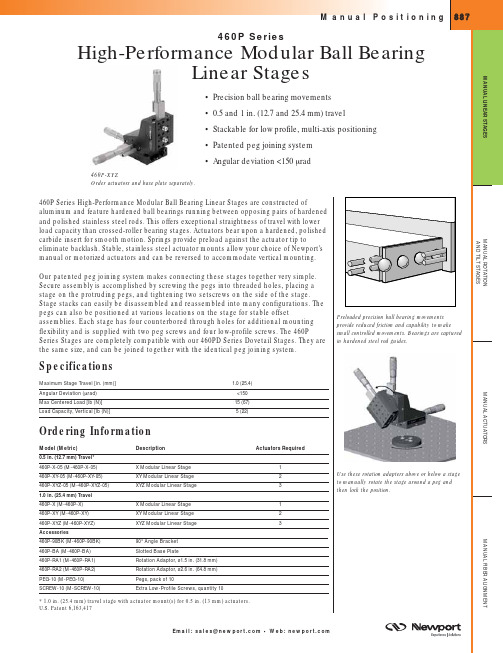
888P h o n e : 1-800-222-6440 • F a x : 1-949-253-1680M a n u a l P o s i t i o n i n gM A N U A L R O T A T I O N A N D T I L T S T A G E SM A N U A L F I B E R A L I G N M E N TM A N U A L A C T U A T O R SM A N U A L L I N E A R S T A G E SRecommended ActuatorsManual DrivesDescription460P-05460PTravel (mm)Sensitivity (µm)AJS Series (page 921)Fine Adjustment Screw ••13–250.6–0.6 -0.75SM-13(page 923)Micrometer •131SM-25(page 923)Micrometer •251HR-13(page 925)High-Resolution Micrometer•130.5HR-1Long Travel, High-Resolution Micrometer •250.25DM-13(page 928)Differential Micrometer •130.1DM-13L (page 926)Differential Micrometer •130.1DM-25L (page 926)Differential Micrometer•250.1Motorized DrivesLTA-HS (page 836)Motorized Actuator ••500.1CMA Series (page 839)Motorized Actuator ••12.5–250.2–0.5PZA12 Actuator (page 834)NanoPZ actuator, 12.5mm travel••12.50.03Pegs are used to securely attach the stages together,allowing quick assembly and great flexibility.Four counterbored holes in the base can be used for bolting the stage down.460P-XY (M-460P-XY)Model 460P-BA8 Holes, Thd B, D x E Spacing8 Holes, Thd B, ø D Spacing2.400(61.0)4.000 (101.6) Typ.524 (13.3)Typ.250 (6.4)8 Slots, Thd B CLR 4.500 (114.3)ED Model 460P-RA1.320(8.12)2X #8-32 LOCKINGSET SCREWSNEAR AND FAR SIDES4X 1/4-20 THD THRU ON 1.00 INCH SPACING (M6 THD THRU ON 25.0MM SPACING )2X #8-32 THD THRU ON 1.00 INCH SPACING (M4 THD THRU ON 25.0MM SPACING ).75(19.0).75(19.0)1.50(Ø38.1).375(Ø9.5)THRU FOR PEGModel 460P-90BK2.375(60.3)1.188 (30.2)2X "Peg" Insertion Hole2.375(60.3)2.675 (67.9)11 Holes, Thd B,C Spacing4 Holes, Thd A,D SpacingModel 460P-RA22X #8-32 LOCKINGSET SCREWNEAR AND FAR SIDES12X 1/4-20 THD THRU ON 1.00 INCH SPACING (M6 THD THRU ON 25.0MM SPACING )4X #8-32 THD THRU ON 1.00 INCH SPACING (M4 THD THRU ON 25.0MM SPACING )1.275(32.4).32(8.1)1.275(32.4)2.55(Ø64.8).375(Ø9.5)THRU FOR PEGThreadDimensions [in. (mm)]Model (Metric)AB CD E 460P-BA (M-460P-BA)1/4-20 (M6) 1.000 (25.0) 2.000 (50.0)460P-90BK (M-460P-90BK)8-32 (M4)1/4-20 (M6)0.500 (12.5)1.000 (25.0)See our website for CAD filesCADModel PEG-101/4-20(M6).30 (7.6).22 (5.6)ø .374(9.5)Pegs allow secure and rigid offset mounting.E m a i l : s a l e s @n e w p o r t.c o m • We b : n e w p o r t.c o mM a n u a l P o s i t i Model 460P-XModel 460P-XYModel 460P-XYZThreadDimensions [in. (mm)]Model (Metric)A B C D E 460P-X (M-460P-X)8-32 (M4)1/4-20 (M6)0.500 (12.5) 1.000 (25.0) 2.000 (50.0)460P-XY (M-460P-XY)8-32 (M4)1/4-20 (M6)0.500 (12.5) 1.000 (25.0) 2.000 (50.0)460P-XYZ (M-460P-XYZ)8-32 (M4)1/4-20 (M6)0.500 (12.5)1.000 (25.0)2.000 (50.0)460P-X (M-460P-X)460P-BA (M-460P-BA)PEG-10 (M-PEG-10)The 90°。
