GB204AHGABNUB-V01中文资料
GB204AHGAAMLB-V01中文资料
JEWEL HILL ELECTRONIC CO.,LTDJEWEL HILL ELECTRONIC CO.,LTD.SPECIFICATIONS FORLCD MODULEModule No. GB204AOffice Address: Rm. 518,5/F., 101 Shangbu Industrial District,HuaqiangNorthRoad, Shenzhen, ChinaTEL : (86)-755-83362489 83617492FAX: (86)-755-83286396 83365871E-mail: sales@jhlcd@Website: TABLE OF CONTENTSLCM NUMBER SYSTEM (2)1. GENERAL DESCRIPTION (3)2. FEATURES (3)3. MECHANICAL SPECIFICATION (3)4. MECHANICAL DIMENSION (4)5. MAXIMUM RATINGS (5)6. ELECTRICAL CHARACTERISTICS (5)7. MODULE FUNCTION DESCRIPTION (6)8. ELECTRO-OPTICAL CHARACTERISTICS (12)9. RELIABILITY (16)10. PRECAUTIONS FOR USING LCD MODULES (17)11. USING LCD MODULES (19)12. REVISION HISTORY (21)SAMPLE APPROVED REPORT (22)LCM Number SystemNUMBER OF CHAR. PER LINE F: FSTN; X: OTHER VERSION NUMBER: V00~V99IC TYPE:VIEWING DIRECTION:TEMPERATURE RANGE:BACKLIGHT TYPE:SERIAL NUMBER: A~ZGRAPHIC MODULEs: NUMBER OF COMMONs GRAPHIC MODULEs:NUMBER OF SEGMENTs COB & SMT LCMBACKLIGHT COLOR:CHARACTER MODULEs:CHARACTER MODULEs: NUMBER OF LINE G: REFLECTIVE,NONE BACKLIGHT A: TRANSFLECTIVE, EL BACKLIGHT B: TRANSMISSIVE, EL BACKLIGHT C: TRANSFLECTIVE, LED BACKLIGHT D: TRANSMISSIVE, LED BACKLIGHT E: TRANSFLECTIVE, CCFL BACKLIGHT F: TRANSMISSIVE, CCFL BACKLIGHT A: AMBER; B: BLUE; Y: YELLOW-GREEN R: RED; W: WHITE; O: THER COLOR N: NORMAL TEMPERATURE RANGE U: UPPER(12:00); D: DOWN(6:00)L: LEFT(9:00); R: RIGHT(3:00);A: BONDING IC, WITH CONTROLLER B: BONDING IC, WITHOUT CONTROLLER C: SMT IC, WITH CONTROLLER D: SMT IC, WITHOUT CONTROLLER O: OTHER TYPEW: BLACK-WHITE; O: OTHER G: GRAY; Y: YELLOW-GREEN; B: BLUE; LCD COLOR MODE:N: TN; H: HTN; S: STN LCD TYPE:S: SUPER WIDE TEMPERATURE RANGE W: WIDE TEMPERATURE RANGEM: MIDDLE TEMPERATURE RANGE1. GENERAL DESCRIPTIONThe GB204A is a 20C x 4L Character LCD module. It has a STN panel composed of 200 segmentsand 16 commons. The LCM can be easily accessed by micro-controller via parallel interface.2. FEATURESTransflective and positiveDisplay ModeSTN(Yellow - Green) moduleDisplay Format Character 20C x4LInput Data 8/4-bit parallel data input from MPUMultiplexing Ratio 1/16 DutyBiasBias 1/5Viewing Direction 6 O’clockBacklight LED3. MECHANICAL SPECIFICATIONItem Specifications Unit Dimensional outline 98.0 x 60.0 x 13.5(max) mmResolution 200segs x 16coms dotsActive area 70.4(W) x 20.8(H) mmChar. pitch 3.55(W) x 5.35(H) mmChar. size 2.95(W) x 4.75(H) mmDots pitch 0.6 (W)×0.6(H) mmDots size 0. 55(W)×0.55(H) mm4. MECHANICAL DIMENSION5. MAXIMUM RATINGSItem Symbol Min Max Unit NoteV DD - V ss -0.3 7.0 V Supply voltage V LCD -0.3 13.0 V Input Voltage V IN -0.3 V DD +0.3 VOperating temperature T OPR -10 +60 Storage temperature T STR -20 +70Humidity --- --- 90 %RH6. ELECTRICAL CHARACTERISTICSItem SymbolCondition Min. Typ. Max. UnitSupply Voltage Logic V DD------ 5.0 --- VH level V IH 0.8V DD --- V DDInput VoltageL levelV IL --- V SS --- 0.2V DDVCurrent Consumption(LCD DRIVER)I DDV DD =5.0V;V LCD =4.3V,T amb =25 ;--- --- 1.0 mALCD Driving Voltage V LCDBias=1/5V LCD =V DD -V O--- 4.3 --- VCurrent Consumption (With LED BackLight)I LEDV DD =5.0V;V LED =4.2V,T amb =25 ;--- --- 300 mA7. MODULE FUNCTION DESCRIPTION7.1. PIN DESCRIPTIONPin No. Symbol Description1 VSSPower supply for Ground (0V)2 VDDPower supply for positive (+5V)3 VOLCD driver voltage regulation terminal4 RSData/Command register selection; “H”: Data; “L”: Command5 R/WRead/write selection signal, ”H”: Read; ”L”: Write6 ERead/write Enable signal input pin7 DB08 DB19 DB210 DB38-bit bi-directional data bus11 DB412 DB513 DB614 DB715 LED+Power supply voltage for backlight positive16 LED-Power supply voltage for backlight negative7.2 TIMING CHARACTERISTICS1. SYSTEM BUS READ/WRITE CHARACTERISTIC7.3 APPLICATION OF LCMReference circuitCircuit Block Diagram7.4 TABLE OF COMMAND7.5 CHARACTER GENERATOR ROM8. ELECTRO-OPTICAL CHARACTERISTICSItem Symbol Condition Temp Min Typ. Max UnitsNote4.2 4.5 4.825 4.0 4.3 4.6 LCD driving voltageV LCD = = 050 3.8 4.1 4.4 V NOTE1Rise Time (Tr) --- --- -- Decay Time (Tf)0 --- ---- --- Rise Time (Tr) --- 225 340Decay Time (Tf) 25 --- 240 360Rise Time (Tr) --- --- -- Response TimeDecay Time (Tf)= = 0 50 --- --- --msec NOTE2Contrast Ratio Cr= = 0 255 10 --- --- NOTE4Viewing AngleRange( = 0°)(6”) = 90°(3”) =180°(12”) =270°(9”)(25 ) CR ≥245 35 25 30DegNOTE3z For panel only․Electro-Optical Characteristics Measuring Equipment(DMS501)SystemIllumination (D65)․Note 1. Definition of Driving Voltage( Vlcd) :․Note 3. Definition of Viewing Angle and :․Note 4. Definition of Contrast ratio( CR) :Brightness of Non-selected Segment (B2)Brightness of Selected Segment (B1)CR =V,maxCR,maxDriving VoltageB r i gh t n e s s (%)Brightness Curve forSelected Segment0%=90 =270Viewing Direction 6 O’clock DirectionNormal :9. RELIABILITY9.1. MTBFThe LCD module shall be designed to meet a minimum MTBF value of 50000 hours with normal. (25°C in the room without sunlight)9.2. TESTSNO. ITEM CONDITION CRITERION1 High Temperature Operating 60 120Hrs2 Low Temperature Operating -10 120Hrs3High Temperature/Humidity Non-Operating60 ,90%RH ,120 Hrs4 High TemperatureNon-Operating70 120Hrs5 Low TemperatureNon-Operating-20 120Hrs6 Temperature CyclingNon-Operating-10 (30Min )↔ 60 (30Min)10 CYCLESNo Defect OfOperational Function InRoom Temperature AreAllowable.IDD of LCM inPre-and post-test shouldfollow specificationNotes: Judgments should be mode after exposure in room temperature for two hours.10. PRECAUTIONS FOR USING LCD MODULES10.1. HANDLING PRECAUTIONS(1) The display panel is made of glass. Do not subject it to a mechanical shock or impact by droppingit.(2) If the display panel is damaged and the liquid crystal substance leaks out, be sure not to get any inyour mouth. If the substance contacts your skin or clothes, wash it off using soap and water.(3) Do not apply excessive force to the display surface or the adjoining areas since this may cause thecolor tone to vary.(4) The polarizer covering the display surface of the LCD module is soft and easily scratched. Handlethis polarizer carefully.(5) If the display surface becomes contaminated, breathe on the surface and gently wipe it with a softdry cloth. If it is heavily contaminated, moisten a cloth with one of the following solvents: - Isopropyl alcohol- Ethyl alcohol(6) Solvents other than those above mentioned may damage the polarizer.Especially, do not use the following:- Water- Ketone- Aromatic solvents(7) Extra care to minimize corrosion of the electrode. Water droplets, moisture condensation or acurrent flow in a high-humidity environment accelerates corrosion of the electrode.(8) Install the LCD Module by using the mounting holes. When mounting the LCD Module, makesure it is free of twisting, warping and distortion. In particular, do not forcibly pull or bend the I/Ocable or the backlight cable.(9) Do not attempt to disassemble or process the LCD Module.(10) NC terminal should be open. Do not connect anything.(11) If the logic circuit power is off, do not apply the input signals.(12) To prevent destruction of the elements by static electricity, be careful to maintain an optimumwork environment.- Be sure to ground the body when handling he LCD Module.- Tools required for assembling, such as soldering irons, must be properly grounded.-To reduce the amount of static electricity generated, do not conduct assembling and other workunder dry conditions.-The LCD Module is coated with a film to protect the display surface. Exercise care when peeling off this protective film since static electricity may be generated.10.2. STORAGE CONDITIONSWhen storing, avoid the LCD module to be exposed to direct sunlight of fluorescent lamps. For stability, to keep it away form high temperature and high humidity environment (The best condition is : 23±5°C, 45±20%RH). ESD protection is necessary for long-term storage also.10.3. OTHERSLiquid crystals solidify under low temperature (below the storage temperature range) leading to defective orientation or the generation of air bubbles (black or white). Air bubbles may also be generated if the module is subject to a low temperature.If the LCD Module have been operating for a long time showing the same display patterns the display patterns may remain on the screen as ghost images and a slight contrast irregularity may also appear.A normal operating status can be recovered by suspending use for some time. It should be noted that this phenomenon does not adversely affect performance reliability.To minimize the performance degradation of the LCD Module resulting from destruction caused by static electricity etc. exercise care to avoid holding the following sections when handling the modules.- Exposed area of the printed circuit board.- Terminal electrode sections.11. Using LCD modules11.1 LIQUID CRYSTAL DISPLAY MODULESLCD is composed of glass and polarizer. Pay attention to the following items when handling.(1) Please keep the temperature within specified range for use and storage. Polarization degradation,bubble generation or polarizer peel-off may occur with high temperature and high humidity.(2) Do not touch, push or rub the exposed polarizers with anything harder than a HB pencil lead (glass,tweezers, etc).(3) N-hexane is recommended for cleaning the adhesives used to attach front/rear polarizers andreflectors made of organic substances, which will be damaged by chemicals such as acetone, toluene, toluene, ethanol and isopropyl alcohol.(4) When the display surface becomes dusty, wipe gently with absorbent cotton or other soft materiallike chamois soaked in petroleum ether. Do not scrub hard to avoid damaging the display surface.(5) Wipe off saliva or water drops immediately, contact with water over a long period of time maycause deformation or color fading.(6) Avoid contacting oil and fats.(7) Condensation on the surface and contact with terminals due to cold will damage, stain orpolarizers. After products are tested at low temperature they must be warmed up in a container before coming is contacting with room temperature air.(8) Do not put or attach anything on the display area to avoid leaving marks on.(9) Do not touch the display with bare hands. This will stain the display area and degrade insulationbetween terminals (some cosmetics are determinate to the polarizers).(10)As glass is fragile, it tends to become or chipped during handling especially on the edges. Pleaseavoid dropping or jarring.11.2 INSTALLING LCD MODULEAttend to the following items when installing the LCM.(1) Cover the surface with a transparent protective plate to protect the polarizer and LC cell.(2) When assembling the LCM into other equipment, the spacer to the bit between the LCM and thefitting plate should have enough height to avoid causing stress to the module surface, refer to the individual specifications for measurements. The measurement tolerance should be ±0.1mm.11.3 ELECTRO-STATIC DISCHARGE CONTROLSince this module uses a CMOS LSI, the same careful attention should be paid for electrostatic discharge as for an ordinary CMOS IC.(1) Make certain that you are grounded when handing LCM.(2) Before removing LCM from its packing case or incorporating it into a set, be sure the module andyour body have the same electric potential.(3) When soldering the terminal of LCM, make certain the AC power source for the soldering irondoes not leak.(4) When using an electric screwdriver to attach LCM, the screwdriver should be of groundpotentiality to minimize as much as possible any transmission of electromagnetic waves produced sparks coming from the commutator of the motor.(5) As far as possible, make the electric potential of your work clothes and that of the workbenches tothe ground potential.(6) To reduce the generation of electro-static discharge, be careful that the air in the work is not toodried. A relative humidity of 50%-60% is recommended.11.4PRECAUTIONS FOR OPERATION(1) Viewing angle varies with the change of liquid crystal driving voltage (Vo). Adjust Vo to showthe best contrast.(2) Driving the LCD in the voltage above the limit will shorten its lifetime.(3) Response time is greatly delayed at temperature below the operating temperature range. However,this does not mean the LCD will be out of the order. It will recover when it returns to the specified temperature range.(4) If the display area is pushed hard during operation, the display will become abnormal. However, itwill return to normal if it is turned off and then on.(5) Condensation on terminals can cause an electrochemical reaction disrupting the terminal circuit.Therefore, this product must be used and stored within the specified condition of 23±5°C, 45±20%RH.(6) When turning the power on, input each signal after the positive/negative voltage becomes stable.11.4 SAFETY(1) It is recommended to crush damaged or unnecessary LCDs into pieces and wash them off withsolvents such as acetone and ethanol, which should later be burned.(2) If any liquid leaks out of a damaged glass cell and comes in contact with the hands, wash offthoroughly with soap and water.12. REVISION HISTORYrecord Date Version Reviseversion 05-01-011.0 Original2.0 Change specification format 05-11-193.0 Change contact mode 06-07-30SAMPLE APPROVED REPORT。
E203-V01 喷码机培训教材

(Stock Code : 1997)
噴碼機培训教材
编写人员: 羅建星 编写日期:2012/11/22 审 核﹕
职称:副課長 REV:1.1 核准﹕
0
教材變更履歷
變更日期
變更內容
變更頁數
生效日期
擔當
1
课 程 大 纲
教學時數: 1H
课程编号
课程名称 工傷預防及處理流程 选用对象 课程目标:让学員了解撐握噴碼機工作原理及保養事項 教学大约/重点内容 一、前言 二、概念與定义 教学方法 讲授法 讲授法 教学资源 時數 5分钟 10分钟 备注 ME人員
• 5.2清洗噴頭
充電極 噴嘴片
偏轉板 負極
偏轉板 正極
回收管
• 按上圖範圍清洗,嚴禁將溶劑噴射到其它區域。
14
四.噴碼機保養功能
• 6.調整墨線 • 在清洗噴嘴及拆洗噴嘴片后,仍未能改善墨線片射的時候, 採取調教噴嘴位置,使墨線射進回收管中央。
噴嘴與噴頭需垂直平行
水平方向鎖緊螺絲 垂直方向鎖緊螺絲
• c.按右下角執行鍵,如下:
•
•
如需中斷操作,按右下角中斷鍵,屏幕提示將回收用軟管復 位后,按執行鍵,屏幕返回循環控制版面。
• d.廢棄處理完畢。
11
四.噴碼機保養功能
• e.將回收用軟管復位,按操作說明要求改變墨水過濾器的方向 。
• f.待墨水沖入完畢后,打開運行管理版面,將運行時間復位為 0.
12
四.噴碼機保養功能
• 5.1噴嘴逆清洗 • a.打開循環控制面板,按噴嘴逆清洗及執行。 • b.用洗壺將溶劑噴在噴嘴片處,真空作用溶劑倒吸入噴嘴內。
• c.清洗過程1分鐘,如需提前終止,點擊中斷。 • d.将喷头清洗部分用吹球吹干。 注:喷嘴逆清洗程序不能超过三次,以免造成墨水变稀。
204-10SUBC-C470-S400-A6中文资料
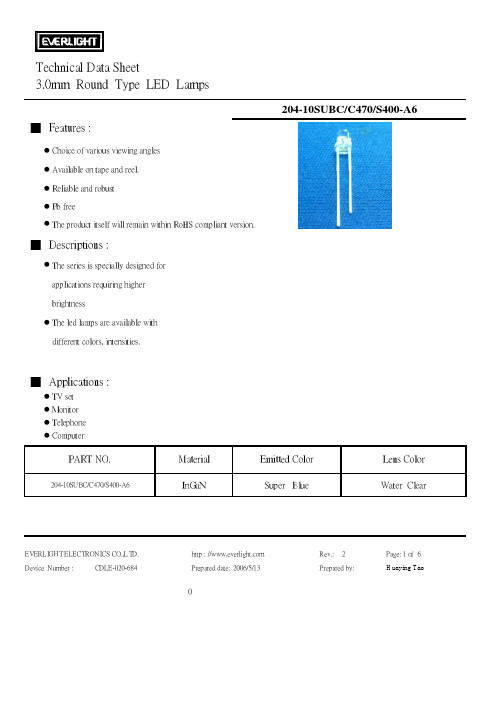
Technical Data Sheet3.0mm Round Type LED Lamps█ Features :●Choice of various viewing angles ●Available on tape and reel.●Reliable and robust ●Pb free●The product itself will remain within RoHS compliant version.█ Descriptions :●The series is specially designed forapplications requiring higher brightness●The led lamps are available with different colors, intensities.█ Applications :●TV set ●Monitor ●Telephone ●Computer204-10SUBC/C470/S400-A6InGaNSuper BlueWater ClearEVERLIGHT ELECTRONICS CO.,LTD.http : // Rev.:2Page: 1 of 6Device Number :CDLE-020-684Prepared date:2006/5/13Prepared by:Huaying Tao204-10SUBC/C470/S400-A6Lens ColorPART NO.MaterialEmitted ColorTechnical Data Sheet█ Absolute Maximum Ratings at Ta = 25℃Parameter Symbol Rating UnitForward Current I F 25mA Operating Temperature Topr -40 to +85℃Storage Temperature Tstg -40 to +100℃ESD 150V Soldering Temperature Tsol 260 ± 5℃Power Dissipation Pd 110mW Reverse VoltageV R5VNote: *1:Soldering time ≦ 5 seconds.EVERLIGHT ELECTRONICS CO.,LTD.http : // Rev.:2Page: 2 of 6Device Number :CDLE-020-684Prepared date:Prepared by:Huaying TaoElectrostatic Discharge 2006/5/13Technical Data Sheet3.0mm Round Type LED LampsElectro-Optical Characteristics (Ta=25℃)SymbolMin.Typ.Max.UnitVF I F =20mA / 3.4 4.0VIR V R =5V //50μAIv I F =20mA 2550/mcd2θ1/2I F =20mA /20/degλp I F =20mA /468/nmλd I F =20mA /470/nm△λI F =20mA /35/nmEVERLIGHT ELECTRONICS CO.,LTD.http : // Rev.:2Page: 3 of 6Device Number :CDLE-020-684Prepared date:Prepared by:Huaying Tao204-10SUBC/C470/S400-A6ConditionParameter2006/5/13Peak Wavelength Dominant Wavelength Spectrum RadiationBandwidthForward Voltage Reverse Current Luminous Intensity Viewing AngleTechnical Data Sheet3.0mm Round Type LED Lamps█Reliability test items and conditions:The reliability of products shall be satisfied with items listed below. Confidence level:97% LTPD:3%NO Item Test ConditionsSample SizeFailure JudgmentCriteria1Solder Heat TEMP : 260℃ ± 5 ℃76 PCS H : +100℃ 15min2Temperature Cycle∫ 5 min 76 PCSL : -40℃ 15min H : +100℃ 5min3Thermal Shock ∫ 10 sec 76 PCSL : -10℃ 5min 4High TemperatureStorage TEMP : 100℃76 PCS 5Low TemperatureStorage TEMP : -40℃76 PCS TEMP : 25℃I F = 20mA 7High Temperature /High Humidity85℃ / 85% RH76 PCSNote:Ivt:To test Iv value of the chip before the reliablility testIv:The test value of the chip that has completed the reliablility test U:Upper Specification Limit L: Lower Specification LimitEVERLIGHT ELECTRONICS CO., http : // Rev.:2 Page: 5 of 6Device Number :CDLE-020-684Prepared by:Huaying TaoPrepared date:2006/5/13Test Hours/Cycle 10 SEC0/176 PCS 300 CYCLES 300 CYCLES1000 HRS 6DC Operating Life Ac/Re0/10/10/10/10/10/1Iv≦Ivt*0.5 or Vf≧U orVf≦L1000 HRS 1000 HRS 1000 HRS204-10SUBC/C470/S400-A6Technical Data Sheet3.0mm Round Type LED LampsEVERLIGHT ELECTRONICS CO.,LTD. http : // Rev.:2 Device Number :CDLE-020-684Prepared date:2006/5/13 Prepared by:Page: 6 of 6 Huaying Tao。
贝加莱50点壁厚控制器说明书3.30

PP41型壁厚控制器使用说明书贝加莱工业自动化(上海)有限公司目录系统特性简介 (3)1系统特性介绍 (3)2控制系统各部件介绍 (4)2.1控制操作面板 (4)2.1.1 面板 42.1.2 接口 52.1.3 性能 62.1.4 安装 62.2功能按键及指示灯 (7)2.3控制器及接线 (9)2.3.1AI351 (9)2.3.2 Am351 (10)2.3.3 PP41自带输入 (10)2.3.4 PP41自带输出 (11)3画面操作说明 (12)3.1登陆画面 (12)3.2连续式型胚曲线设定画面 (12)3.2.1 操作按钮 (12)3.2.2 输入参数 (13)3.2.3 输出参数 (14)3.2.4 插入与删除设定数值点 (14)3.2.5 微调设定数值点间的曲线单元 (15)3.3储料式型胚曲线设定画面 (17)3.3.1 操作按钮 (17)3.3.2 输入参数 (18)3.3.3 输出参数 (19)3.4曲线跟踪画面 (19)3.5标记画面 (20)3.6存储画面 (20)3.7文件改名画面 (21)3.8参数存储画面 (21)3.9文件调出画面 (22)3.10监控画面 (22)3.11数据1(曲线点)画面 (22)3.12数据2画面 (23)3.13初始设定画面 (23)3.13.1 输入参数 (23)3.13.2 模式转换 (24)3.14型芯设定画面 (24)3.14.1 输入参数 (24)3.14.2 输出参数 (25)3.14.3 手动调校 (25)3.14.4 自动调校 (25)3.14.5 调校提示: (25)3.15储料设定画面 (26)3.15.1 输出参数 (26)3.15.2 手动调校 (26)3.16增益设定画面 (26)3.16.1 按钮 273.16.2 输入参数 (27)3.16.3 输出参数 (27)3.17时间设定画面 (27)3.17.1 输入参数 (27)3.17.2 输出参数 (27)3.18中英文切换画面 (28)4机器操作说明 (29)4.1开机步骤 (29)4.2系统参数设定 (29)4.2.1 初始设定 (29)4.2.2 型芯设定 (29)4.2.3 储料设定 (29)5故障处理 (30)5.1故障对应 (30)5.2干扰处理 (30)6电源 (30)7附件 (30)系统特性简介1 系统特性介绍这是一款50点型坯壁厚控制器,用来控制中空成型机型坯的壁厚。
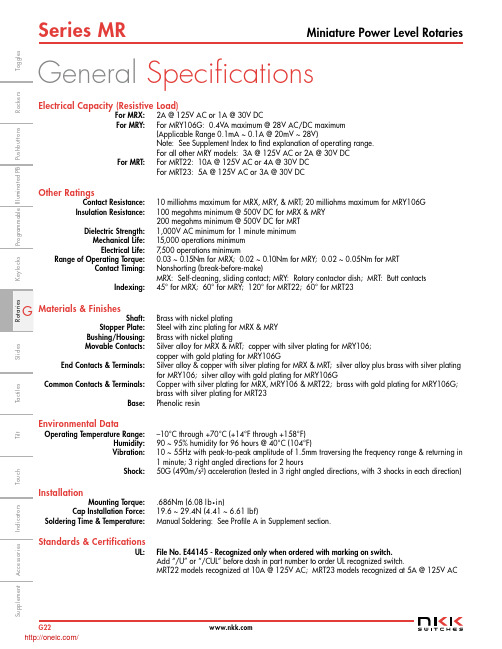
MRT23-A;MRX108-A;MRT22-A;MRX204-A;MRT23;中文规格书,Datasheet资料
(20.0) .787
(5.0) .197
(0.8) .031 Thk = (0.9) .035
Shaft
Terminal
G24 /
1
6
(3.15) Dia .124
T
Shaft Actuated with Solder Lug Terminals *
Poles & Circuits
108 SP with 2-8 Positions 204 DP with 2-4 Positions 402 4P with 2 Positions
106 106G
SP with 2-6 Positions
Installation
Mounting Torque: Cap Installation Force: Soldering Time & Temperature:
.686Nm (6.08 lb•in) 19.6 ~ 29.4N (4.41 ~ 6.61 lbf) Manual Soldering: See Profile A in Supplement section.
SP with 2-6 Positions Gold Contacts 0.4VA
22 DPDT ON-NONE-ON 23 DPDT ON-OFF-ON
Knobs A Plain Black B Small Color Tipped C Large Color Tipped
Colors
For Plain Knob
No Code
Black
For Color Tipped
A
Black
B
White
C
Red
E
Yellow
常用金属材料中日新旧标准牌对照表

Q235-B
SS400
Q235-C
Q235-C
SS400
Q235-D
Q235-D
SS400
Q255-A
SM400A(JISG3106-2004)
Q255-B
SM400B(JISG3106-2004)
Q275
SS490
Q275-A
-
Q275-B
-
Q275-C
SS540
Q275-D
SS540
发至:电 梯 设 计 部、电 梯 技 术 部、扶 梯 技 术 部 和 亚 洲 研 究 开 发 中 心 各 科 室
标 记
处 数
10、优质碳素结构钢
中国现行标准牌号
GB/T699-1999
中国旧标准牌号
GB699-88
日本旧标准牌号
日本现行标准牌号
JISG3131-2005
JISG3506-2004
JISG4051-2005
FCMB35-10
KTH370-12
KT37-12
FCMB37(2000版无此牌号)
KTZ450-06
KTZ45-5
FCMP45-06
KTZ550-04
KTZ50-4
FCMP55-04
KTZ650-02
KTZ60-3
FCMP65-02
KTZ700-02
KTZ70-2
FCMP70-02
白心可锻铸铁
白心可锻铸铁
KTB350-04
-
FCMW34-04
KTB380-12
-
FCMW38-12
KTB400-05
-
FCMW40-05
KTB450-07
电阻器、电位器标准精选(最新)
电阻器、电位器标准精选(最新)G5729《GB/T5729-2003 电子设备用固定电阻器:总规范》G6663.1《GB/T 6663.1-2007 直热式负温度系数热敏电阻器第1部分:总规范》G7154.1《GB/T7154.1-2003 直热式阶跃型正温度系数热敏电阻器:限流用》G7154.2《GB/T7154.2-2003 直热式阶跃型正温度系数热敏电阻器:加热元件用》G7154.3《GB/T7154.3-2003 直热式阶跃型正温度系数热敏电阻器:浪涌电流用》G7154.4《GB/T7154.4-2003 直热式阶跃型正温度系数热敏电阻器:敏感用》G10193《GB/T10193-1997 电子设备用压敏电阻器:总规范》G10194《GB/T10194-1997 电子设备用压敏电阻器:浪涌抑制型压敏电阻器》G10195.1《GB/T 10195.1-1997 电子设备用压敏电阻器:碳化硅浪涌抑制型压敏电阻器评定水平E》G10195.2《GB/T 10195.2-1997 电子设备用压敏电阻器:氧化锌浪涌抑制型压敏电阻器评定水平E》G15883《GB/T15883-1995 电子设备用膜固定电阻网络空白详细规范::评定水平E》G16515《GB/T16515-1996 电子设备用电位器:分规范》G17025《GB/T17025-1997 单圈旋转功率电位器分规范》G17026《GB/T17026-1997 单圈旋转功率电位器评定水平E》G17027《GB/T17027-1997 单圈旋转功率电位器评定水平F》G17028《GB/T17028-1997 单圈旋转低功率电位器评定水平E》G17029《GB/T17029-1997 单圈旋转低功率电位器评定水平F》G17034《GB/T17034-1997 低功率非线绕固定电阻器评定水平F》G17035《GB/T17035-1997 带散热器的功率型固定电阻器评定水平H》GJ244A《GJB 244A-2001 有质量等级的薄膜固定电阻器总规范》GJ601A《GJB601A-1998 热敏电阻器总规范》GJ920A《GJB 920A-2002 膜固定电阻网络、膜固定电阻和陶瓷电容的阻容网络通用规范》GJ955A《GJB 955A-2003 贵金属及其合金电位器绕组裸丝材规范》GJ956A《GJB 956A-2003 电阻应变铂钨合金片、带、箔、丝材规范》GJ1782《GJB1782-1993 压敏电阻器总规范》GJ1809《GJB1809-1993 模拟直流高值电阻器通用规范》GJ2828《GJB2828-1997 功率型线绕固定电阻器总规范》SJ10774《SJ/T10774-2000 电子元器件详细规范:RT14型碳膜固定电阻器评定水平E》SJ10775《SJ/T10775-2000 电子元器件详细规范:RT14型金属膜固定电阻器评定水平E》SJ10798《SJ/T10798-2000 电子元器件详细规范MF11型直热式温度负系数热敏电阻器评定水平》SJ10799《SJ/T10799-2000 电子元器件详细规范:MF53-1型直热式负温度系数热敏电阻器评定水平E》SJ10872《SJ/T10872-2000 电子元器件详细规范RJ15型金属膜固定电阻器评定水平E》SJ11113《SJ/T11113-1999电子元器件详细规范RJ型金属膜固定电阻器评定水平E》SJ11267《SJ/T11267-2002 电子设备用压敏电阻器安全要求》SJ11255《SJ/T11255-2001叠层型片式电感器详细规范》SJ11267《SJ/T11267-2002 电子设备用压敏电阻器安全要求》SJ11278《SJ/T11278-2002 电子设备用压敏电阻器:防雷型压敏电阻器》SJ11279《SJ/T11279-2002 电子设备用压敏电阻器:防雷指示型过电压保护器评定水平E》SJ20647《SJ20647-1997 铂热敏电阻器总规范》SJ20794《SJ20794-2000 表面安装膜固定电阻网络总规范》SJ20857《SJ20857-2002电阻箔复合材料规范》SJ52828/1《SJ52828/1-1998RXG9功率线绕固定电阻器详细规范》J6319《JB/T 6319-2010 电阻器基本技术要求》YS613《YS/T 613-2006 碳膜电位器用电阻浆料》。
204中文说明书

GSW型光栅数显系统(中文液晶提示)使用说明书成都远山机电产品有限公司尊敬的用户:欢迎您使用远山机电最新开发液晶中文提示的GSW 光栅数显系统,远山机电光栅系统广泛用于铣床、磨床、镗床、线切割、车床、电火花加工设备,它的应用有助于提高生产效率、显示直观、操作方便、精度准确、重复性稳定,是模具制造业、机械加工业、精密测量仪器必不可少的装置。
本系统设置多种智能化功能,如SDM300点记忆、等分圆和椭圆、斜面加工、R的加工8个面选择、分中功能的用法,还配置了计算器,等等功能,使用起来十分方便。
应用远山机电的光栅数显系统,不须经过培训,按照中文使用说明书每步提示一看就懂。
最适合刚使用操作的新手,对于熟练的操作者更是得心应手。
要想了解有关的细节请阅读使用说明书。
安全注意事项:打开产品包装,取出箱内数显表与电子尺相接,然后插上电源检查显示是否正常。
①开箱后检查外观是否完好,若有故障应立即联系本公司销售部,切勿自行拆卸维修。
②本装置使用110V~220V,50Hz~60Hz的交流电源,电源插头是带有接地脚的三芯电源插头。
三芯电源插座地线一定要接地牢靠。
③用户不可以自行打开机壳修理,表内有高压电源以免造成人员伤害。
④本机壳是采用ABS工程塑料,不具防爆高温的环境中使用。
⑤平时不用时请关闭电源,可延长本产品使用时间。
⑥在雷雨天气时应关闭或拔掉电源线以免高压雷击电网引起表的电源电压突然猛增高而烧毁表内电源,给用户带来不必要的损失。
日常维护:①每天下班时,清洁时请关闭电源。
②用干布或毛刷擦拭数显表或电子尺防护外壳。
③不能用甲苯或乙醇清洗外壳。
④数显表外壳或显示窗的污迹可用洗衣粉和水搅匀用毛巾扭干水擦拭。
承诺:本公司产品如因用户使用操作不当造成电子尺和数显表的损坏,特别是因碰撞造成产品外观或内部损坏,或自行拆下电子尺限位,造成因超行程把尺撞坏,需本公司维修服务的,本公司要收取适当的材料费和维修费。
面板按键说明GSW-204GSW-304目录功能项目 (7)清零 (8)输入坐标 (8)公/英制显示 (8)ABS/INC坐标 (9)自动分中 (10)RI(寻找师傅零位) (11)半径/直径 (11)计算器 (11)SDM300组记忆 (12)圆周分孔 (18)椭圆分孔 (21)斜线分孔 (25)圆弧加工 (27)平滑圆弧加工 (35)斜面加工 (39)电火花加工 (42)基本参数 (45)高级用户 (46)光栅线位移传感器 (48)光栅线位移动传感器行程和安装尺寸 (51)安装示图 (52)故障分析与处理 (53)GSW-中文提示光栅数显表,中文辅助显示智能表,采用高科技软件电子技术,功能多、易操作、可靠耐用,使机械加工的必备产品。
电子元器件标准精选
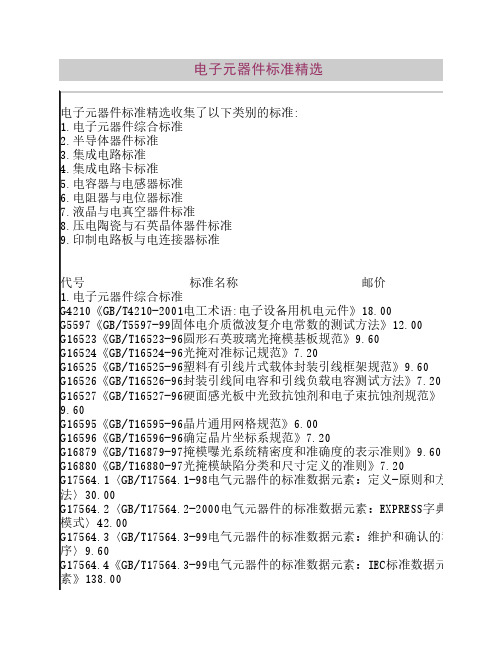
GJ3157《GJB3157-1998半导体分立器件失效分析方法和程序》36.00 GJ3519《GJB3519-99半导体激光二极管总规范》18.00 SJ10585《SJ/T10584—94半导体分立器件表面安装器件外形尺寸》18.00 SJ11225《SJ/T11225-2000电子元器件详细规范:3DA504型S波段硅脉冲功 率晶体管》12.00 SJ11226《SJ/T11226-2000电子元器件详细规范:3DA505型L波段硅脉冲功 率晶体管》12.00 SJ11227《SJ/T11227-2000电子元器件详细规范:3DA98型NPN硅高频大功率 晶体管》14.40 SJ20756《SJ20756-1999半导体分立器件结构相似性应用指南》16.80 SJ20757《SJ20757-1999微波电路系列和品种微波开关系列的品种》19.20 SJ20744《SJ20744-1999半导体材料杂质含量红外吸收光谱分析通用导 则》7.20 SJ20782《SJ20782-2000充气整流管总规范》12.00 SJ20784《SJ20784-2000微型杜瓦总规范》9.60 SJ20785《SJ20785-2000超辐射发光二极管组件测试方法》24.00 SJ20786《SJ20786-2000半导体光电组件总规范》15.60 SJ20787《SJ20787-2000半导体桥式整流器热阻测试方法》9.60 SJ20788《SJ20788-2000半导体二极管热阻测试方法》16.80 SJ20789《SJ20789-2000MOS场效应晶体管热敏参数快速筛选试验方法》 6.00 J9684《JB/T9684-2000电力半导体器件用散热器选用导则》26.40 J10096《JB/T10096-2000电力半导体器件用管壳选用导则》16.80 J10097《JB/T10097-2000电力半导体器件用管壳》26.40 DB723〈电力半导体器件和半导体变流器标准〉(93电工版)103.50.00 DB735〈电力半导体器件标准〉(93电工版)92.00 DB795〈电力半导体器件和整流设备标准(1)〉(94电工版)50.00 DB827〈电力半导体器件和整流设备标准(2)〉(95电工版)84.00 DB827〈电力半导体器件和整流设备标准(3)〉(96电工版)48.00 DB887〈电力半导体器件和整流设备标准(4)〉(97电工版)60.00 DB930〈电力半导体器件和整流设备标准(5)〉(98电工版)48.00 DB982〈电力半导体器件专业卷(1)〉(2000电工版)126.50 3.集成电路标准 G4377〈GB/T4377-96半导体集成电路电压调整器测试方法和基本原理〉 18.00 G5965〈GB/T5965-2000集成电路:双极型单片数字集成电路门电路空白详
巨鹰Giant204 四通道称重模块 用户手册说明书

Giant204四通道称重模块用户手册 V1.0目录1 技术支持 (3)2 产品介绍 (4)3 技术参数 (5)4 外形尺寸,电气连接以及选型 (6)4.1 外形尺寸 (6)4.2 电气连接与说明 (6)4.2.1 称重传感器连接 (7)4.2.2 指示灯 (8)4.2.3 通信接口RS232/RS485 (8)4.3 选型 (8)5 显示与按键 (9)6 功能与设置 (10)6.1 主界面显示与功能 (11)6.1.1 相关指令 (12)6.2功能菜单 (15)6.2.1 相关指令 (16)6.3校准菜单 (21)6.3.1 校准方式选择菜单 (21)6.3.2 实物校准菜单 (22)6.3.3 数字校准菜单 (24)6.3.4 相关指令 (25)6.4 参数保存菜单 (27)6.4.1相关指令 (27)6.5 显示设置菜单 (28)6.5.1相关指令 (28)6.6 通信设置菜单 (29)6.6.1 相关指令 (30)7 MODBUS通讯协议 (33)8用户设置软件 (40)8.1 软件安装与启动 (40)9 附件 (41)9.1 仪表显示的错误代码 (41)9.2 基本术语 (41)9.3 标准ASCII码 (42)1 技术支持感谢您选择并使用大连哲勤科技有限公司产品,此用户手册协助您了解并正确使用设备。
如需订购产品、技术支持、以及产品信息反馈,请通过以下方式联系我们。
请在联系时附注设备的购买时间,购买方式,联系人信息,地址以及电话等相关信息,便于我们为您服务。
网址E-Mail**************电话+86-411-66831953, 4000-511-521传真+86-411-82388125版本控制2 产品介绍Giant204四通道称重变送器是面向工业控制领域的重量变送器,集四个高速称重通道,RS485和RS232通信接口于一体(Modbus-RTU通信协议),同时进行四个重量的独立并行高速检测。
特种劳动防护用品产品生产许可证实施细则

编号:(X)XK02-001特种劳动防护用品生产许可证实施细则2011年1月19日公布 2011年1月19日实施国家质量监督检验检疫总局目录1 总则.....................................................................2 工作机构.................................................................3 企业申请生产许可证的基本条件.............................................4 许可程序................................................................. 申请和受理................................................................ 企业实地核查.............................................................. 产品抽样与检验............................................................ 审定与发证................................................................ 集团公司的生产许可........................................................5 审查要求................................................................. 企业生产特种劳动防护用品应执行的产品标准及相关标准........................ 企业生产特种劳动防护用品必备的生产设备和检测设备.......................... 特种劳动防护用品出厂检验项目.............................................. 特种劳动防护用品生产许可证企业实地核查办法................................ 特种劳动防护用品生产许可证检验规则........................................6 证书和标志............................................................... 证书...................................................................... 标志......................................................................7 委托加工备案程序.........................................................8 监督检查.................................................................9 收费.....................................................................10 生产许可证工作人员守则..................................................11 附则.................................................................... 附件1 特种劳动防护用品生产许可证检验机构名单及检验产品范围................ 附件2 特种劳动防护用品生产许可证企业实地核查办法.......................... 附件3 生产许可证企业实地核查报告.......................................... 附件4 企业实地核查轻微缺陷项汇总表........................................ 附件5检验报告............................................................. 附件6 本细则与旧版细则主要内容对照表......................................特种劳动防护用品生产许可证实施细则1 总则为了做好特种劳动防护用品生产许可证发证工作,依据《中华人民共和国工业产品生产许可证管理条例》(国务院令第440号)、《中华人民共和国工业产品生产许可证管理条例实施办法》(国家质检总局令第80号)、《国家质量监督检验检疫总局关于修改〈中华人民共和国工业产品生产许可证管理条例实施办法〉的决定》(国家质检总局令第130号)、《关于电线电缆等12类产品生产许可由省级质量技术监督部门负责审批发证的公告》(国家质检总局2009年第16号公告)、《关于摩托车头盔等11类产品生产许可由省级质量技术监督部门负责审批发证的公告》(国家质检总局2010年第89号公告)、《关于印发<工业产品生产许可省级发证工作规范>的通知》(国质检监[2006]413号)等规定,制定本实施细则。
手持式交流平板砂光机-2023最新标准
手持式交流平板砂光机1范围本文件规定了手持式交流平板砂光机的术语和定义、基本参数、技术要求、试验方法、检验规则、标志、包装、运输与贮存。
本文件适用于一般环境条件下,由单相串励电动机驱动偏心机构,使旋转运动变为摆动,并在平板上装有刚玉或其他磨料的砂纸(或砂布)对木材、金属材料等表面进行砂磨的手持式电动摆动式平板砂光机(以下简称砂光机)。
本文件不适用于单相异步鼠笼型电动机驱动的摆动式平板砂光机、电池供电的砂光机。
2规范性引用文件下列文件中的内容通过文中的规范性引用而构成本文件必不可少的条款。
其中,注日期的引用文件,仅该日期对应的版本适用于本文件;不注日期的引用文件,其最新版本(包括所有的修改单)适用于本文件。
GB/T 191包装储运图示标志(ISO 780:1997,MOD)GB/T 1002家用和类似用途单相插头插座型式、基本参数和尺寸GB/T 2099.1家用和类似用途单相插头插座第1部分:通用要求(GB/T 2099.1—2008IEC 60884-1:2006,E3.1MOD)GB/T 2900.28电工名词术语电动工具GB/T 4208-2017外壳防护等级GB/T 3883.1-2014手持式、可移式电动工具和园林工具的安全第1部分:通用要求GB/T 3883.204-2019手持式、可移式电动工具和园林工具的安全第204部分:手持式非盘式砂光机和抛光机的专用要求(IP代码)(IEC 60529:2013,IDT)GB 4343.1家用电器、电动工具和类似器具的电磁兼容要求第1部分:发射GB/T 5013.4-2008额定电压450/750V 及以下橡皮绝缘电缆第4部分:软线和软电缆(IEC 60245-4:2004,IDT)GB/T 5023.5-2008额定电压450/750V及以下聚氯乙烯绝缘电缆第5部分:软电缆(软线)(IEC 60227-5:2003,IDT)GB 17625.1电磁兼容限值谐波电流发射限值(设备每相输入电流≤16A)GB/T 17625.2电磁兼容限值对每相额定电流≤16A且无条件接入的设备在公用低压供电系统中产生的电压变化、电压波动和闪烁的限制SJ/T 11364-2014电子电气产品有害物质限制使用标识要求3术语和定义GB/T 2900.28、GB/T 3883.1-2014界定的以及下列术语和定义适用于本文件。
不锈钢牌号对照表之欧阳文创编

不锈钢牌号对照表
欧阳文创编
欧阳文创编
欧阳文创编
欧阳文创编
世界金属牌号对照表
碳素结构钢
欧阳文创编
欧阳文创编
[返回]优质碳素结构钢
欧阳文创编
欧阳文创编
欧阳文创编
欧阳文创编
欧阳文创编
[返回]碳素工具钢
欧阳文创编
[返回]合金结构钢
欧阳文创编
欧阳文创编
欧阳文创编
欧阳文创编
欧阳文创编
欧阳文创编
[返回]淬透性合金结构钢
欧阳文创编
欧阳文创编
[返回]弹簧钢
欧阳文创编
[返回]滚动轴承钢
[返回]高速工具钢
欧阳文创编
欧阳文创编
[返回]不锈耐酸钢
欧阳文创编
欧阳文创编
欧阳文创编
[返回]耐热钢
欧阳文创编
欧阳文创编
[返回]易切结构钢
欧阳文创编
合金工具钢
欧阳文创编
欧阳文创编
欧阳文创编
欧阳文创编。
B21 7130-09-2004-A-中文
B21 7130
电气和电子装备环境 通用技术规范
物理-化学特性
本标准部分代替标准 B21 7090
页码 1/16
目录
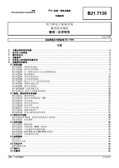
1 主题内容和使用范围 ···················································································································································3 2 在文件上的表述 ···························································································································································3 3 缩写和定义 ···································································································································································3 4 试验条件 ·······································································································································································4 5 在设备上的试验的实施向导 ·······································································································································4 6 试验程序和要求 ···························································································································································5
WE01系列全球2片钢球阀,全流量,氮式球说明书
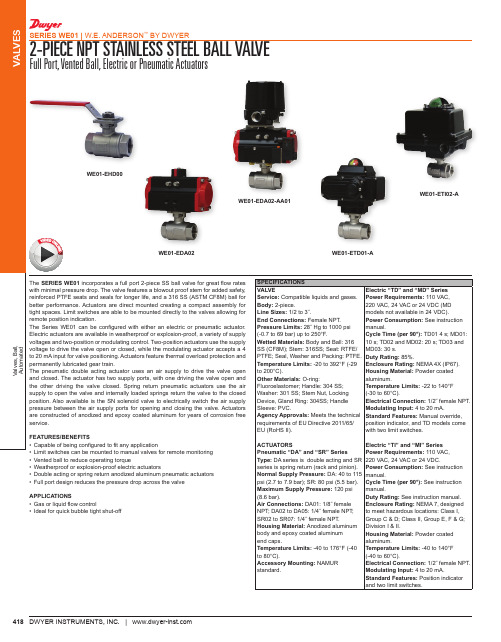
incorporates a full port 2-piece SS ball valve for great flow rates with minimal pressure drop. The valve features a blowout proof stem for added safety, reinforced PTFE seats and seals for longer life, and a 316 SS (ASTM CF8M) ball for mounted creating a compact assembly for tight spaces. Limit switches are able to be mounted directly to the valves allowing for with either an electric or pneumatic actuator. Electric actuators are available in weatherproof or explosion-proof, a variety of supply voltages and two-position or modulating control. Two-position actuators use the supply voltage to drive the valve open or closed, while the modulating actuator accepts a 4 to 20 mA input for valve positioning. Actuators feature thermal overload protection and uses an air supply to drive the valve open and closed. The actuator has two supply ports, with one driving the valve open and Spring return pneumatic actuators use the air supply to open the valve and internally loaded springs return the valve to the closed position. Also available is the SN solenoid valve to electrically switch the air supply pressure between the air supply ports for opening and closing the valve. Actuators are constructed of anodized and epoxy coated aluminum for years of corrosion free SPECIFICATIONSVALVE Service: Compatible liquids and gases.Body: 2-piece.Line Sizes: 1/2 to 3˝.End Connections: Female NPT.Pressure Limits: 28˝ Hg to 1000 psi (-0.7 to 69 bar) up to 250°F.Wetted Materials: Body and Ball: 316 SS (CF8M); Stem: 316SS; Seat: RTFE/PTFE; Seal, Washer and Packing: PTFE.Temperature Limits: -20 to 392°F (-29 to 200°C).Other Materials: O-ring:Fluoroelastomer; Handle: 304 SS; Washer: 301 SS; Stem Nut, Locking Device, Gland Ring: 304SS; Handle Sleeve: PVC.Agency Approvals: Meets the technical requirements of EU Directive 2011/65/Electric “TD” and “MD” Series Power Requirements: 110 VAC, 220 VAC, 24 VAC or 24 VDC (MD models not available in 24 VDC).Power Consumption: See instruction manual.Cycle Time (per 90°): TD01 4 s; MD01: 10 s; TD02 and MD02: 20 s; TD03 and MD03: 30 s.Duty Rating: 85%.Enclosure Rating: Housing Material: aluminum.Temperature Limits: (-30 to 60°C).Electrical Connection: Modulating Input: Standard Features: position indicator, and TD models come with two limit switches.WE01-EDA02WE01-ETD01-AWE01-EDA02-AA01WE01-ETI02-A419Valves, Ball,AutomatedVALVES2-PIECE NPT STAINLESS STEEL BALL VALVEFull Port, Vented Ball, Electric or Pneumatic ActuatorsSERIES WE01 | W.E. ANDERSON ™ BY DWYER®DWYER INSTRUMENTS, INC. | MODEL CHARTSize Cv (gal/min)PopularHand Operated Model PricePopularDouble Acting Pneumatic ModelPrice PopularSpring Return Pneumatic ModelPrice Popular NEMA 4X Two Position Electric (110 VAC) Model Price Popular NEMA 4X Modulating Electric (110 VAC) Model Price 1/2˝3/4˝1˝1-1/4˝1-1/2˝2˝2-1/2˝3˝36.6467.69110.27184.73266.62485.3791.571151.95WE01-CHD00WE01-DHD00WE01-EHD00WE01-FHD00WE01-GHD00WE01-HHD00WE01-IHD00WE01-JHD00$24.75b 37.25b 58.00b 70.50b 108.00b 158.00b 196.00b 434.00bWE01-CDA01WE01-DDA01WE01-EDA02WE01-FDA02WE01-GDA03WE01-HDA03WE01-IDA04WE01-JDA05$186.00b 191.00b 206.00b 258.00b 304.00b 382.00b 567.00b 773.00bWE01-CSR02WE01-DSR02WE01-ESR03WE01-FSR03WE01-GSR04WE01-HSR05WE01-ISR07WE01-JSR07$196.00b 217.00b 258.00b 299.00b 361.00b 464.00b 670.00b 876.00bWE01-CTD01-A WE01-DTD01-A WE01-ETD01-A WE01-FTD01-A WE01-GTD02-A WE01-HTD02-A WE01-ITD03-A WE01-JTD03-A $405.00b 405.00b 428.00b 473.00b 518.00b 563.00b 990.00b 1170.00b WE01-CMD01-A WE01-DMD01-A WE01-EMD01-A WE01-FMD01-A WE01-GMD01-A WE01-HMD02-A WE01-IMD03-A WE01-JMD03-A$720.00b 760.00b 800.00b 920.00b 1040.00b 1200.00b 1360.00b 1440.00bb Items are subject to Schedule B discounts.MODEL CHART - HAND OPERATED & PNEUMATIC ACTUATOR Example WE01-EDA02-A A 01WE01-EDA02-AA01Price Series WE01316 SS 2-piece NPT -Size and Actuator CHD00DHD00EHD00FHD00GHD00HHD00IHD00JHD00CDA01DDA01EDA02FDA02GDA03HDA03IDA04JDA05CSR02DSR02ESR03FSR03GSR04HSR05ISR07JSR071/2˝ hand operated 3/4˝ hand operated1˝ hand operated 1-1/4˝ hand operated 1-1/2˝ hand operated 2˝ hand operated 2-1/2˝ hand operated 3˝ hand operated 1/2˝ double acting 3/4˝ double acting 1˝ double acting 1-1/4˝ double acting 1-1/2˝ double acting 2˝ double acting 2-1/2˝ double acting 3˝ double acting 1/2˝ spring return 3/4˝ spring return 1˝ spring return 1-1/4˝ spring return 1-1/2˝ spring return 2˝ spring return 2-1/2˝ spring return 3˝ spring return$24.75b 37.25b 58.00b 70.50b 108.00b 158.00b 196.00b 434.00b 186.00b 191.00b 206.00b 258.00b 304.00b 382.00b 567.00b 773.00b 196.00b 217.00b 258.00b 299.00b 361.00b 464.00b 670.00b 876.00bSolenoid N A No solenoidNEMA 4X NAMUR solenoid-+50.00bSolenoid Voltage N A B C D E No solenoid 110 VAC220 VAC 24 VAC 24 VDC 12 VDC------Positioner and Switches 000102030406070809None 42AD0 exp limit switch 45VD0 exp position transmitter42AD0-B ATEX limit switch 42AD0-IE IECEX limit switch QV-210101 poly limit switch VPS and P1 prox switch 265ER-D5 positioner 285ER-D5 smart positioner-+230.00b +525.00b +323.00b +320.00b +143.00b +176.00b +620.00b +1389.00bOptions NO Fail open spring return actuator -b Items are subject to Schedule B discounts.MODEL CHART - ELECTRIC ACTUATORExample WE01-GMD01-A WE01-GMD01-A Price Series WE01316 SS 2-piece NPT -Size and Actuator CTD01DTD01ETD01FTD01GTD02HTD02ITD03JTD03CMD01DMD01EMD01FMD01GMD01HMD02IMD03JMD03CTI01DTI01ETI02FTI02GTI02HTI04ITI05JTI06CMI01DMI01EMI02FMI02GMI02HMI04IMI05JMI061/2˝ NEMA 4X two-position 3/4˝ NEMA 4X two-position1˝ NEMA 4X two-position 1-1/4˝ NEMA 4X two-position 1-1/2˝ NEMA 4X two-position 2˝ NEMA 4X two-position 2-1/2˝ NEMA 4X two-position 3˝ NEMA 4X two-position 1/2˝ NEMA 4X modulating 3/4˝ NEMA 4X modulating 1˝ NEMA 4X modulating 1-1/4˝ NEMA 4X modulating 1-1/2˝ NEMA 4X modulating 2˝ NEMA 4X modulating 2-1/2˝ NEMA 4X modulating 3˝ NEMA 4X modulating 1/2˝ exp two-position 3/4˝ exp two-position 1˝ exp two-position 1-1/4˝ exp two-position 1-1/2˝ exp two-position 2˝ exp two-position 2-1/2˝ exp two-position 3˝ exp two-position 1/2˝ exp electric modulating 3/4˝ exp electric modulating 1˝ exp electric modulating 1-1/4˝ exp electric modulating 1-1/2˝ exp electric modulating 2˝ exp electric modulating 2-1/2˝ exp electric modulating 3˝ exp electric modulating $405.00b 405.00b 428.00b 473.00b 518.00b 563.00b 990.00b 1170.00b 720.00b 760.00b 800.00b 920.00b 1040.00b 1200.00b 1360.00b 1440.00b 712.00b 801.00b 810.00b 936.00b 1035.00b 1440.00b 1800.00b 2070.00b 1600.00b 1600.00b 1640.00b 1680.00b 1680.00b 2000.00b 2400.00b 2640.00bActuatorVoltageA B C D 110 VAC 220 VAC 24 VAC 24 VDC--+70.00b +70.00bb Items are subject to Schedule B discounts.ACCESSORIES Model Description Price AFR4VB-01Air filter regulator 0 to 120 psi Volume booster $67.00b 170.00b b Items are subject to Schedule B discounts.REPAIR KITModel Valve Series and Size Price VRK-02VRK-03VRK-04VRK-06VRK-07VRK-08VRK-09WE01-1/2˝WE01-3/4˝WE01-1˝WE01-1-1/2˝WE01-2˝WE01-2-1/2˝WE01-3˝$3.404.605.7011.5015.0030.5049.75Parts List - Included in Kit 1 PTFE thrust washer 1 FKM O-ring2 PTFE stem packing 2 PTFE seals 2 RTFE seats。
D204安装调试大纲正文中文
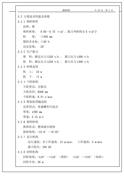
3.2 主要技术性能及参数3.2.1 物料特性品种:煤堆积密度: 0.65~0.78 t/m3,能力考核按0.8 t/m3计粒度:≤300 mm煤的含水份:≤30 %动安息角: 20°3.2.2 生产能力堆料:额定出力1250 t/h ,最大出力1500 t/h取料:额定出力1250 t/h ,最大出力1500 t/h3.2.3 料堆高度轨上: 10 m轨下: -2 m3.2.4 斗轮机构斗轮型式:无格式斗轮直径:6300 mm斗轮转速:6.54 r/min3.2.5 臂架胶带输送机皮带型式:普通槽形可逆式带宽:1200 mm带速:3.15 m/s3.2.6 俯仰机构俯仰形式:整体液压俯仰俯仰角度:-15.6°~+8.02°3.2.7 走行机构走行速度:非工作速度:15 m/min;工作速度:5 m/min最大轮压:250 kN3.2.8 回转机构回转角度:-110°~+110°(堆料) -110°~+110°(取料)回转半径:30 m回转速度:按1/cosΦ变频调速n=0.078~0.156 r/min3.2.9 尾车型式:半趴式单尾车尾车配套皮带带宽:1200 mm带速:3.15 m/s3.2.10 其它:风压:工作状态:250 Pa非工作状态:400 Pa行走距离:~294 m机器重量:~365 t装机容量:~320 kW常用功率:~300 kW整机外形尺寸:(长³宽³高)68.13m³11.17m³21.85m4.安装前的准备本机属大型设备,总重约365t、长约68.13m、宽11.17m、高21.85m,制造厂内总装后无法进行吊运,并且部分构件因尺寸过大运输困难,因而需分开发运,在用户现场再进行整机安装。
4.1 在安装前安装施工单位应按装箱目录及装箱单清点零部件数量是否齐全,检查机器零部件是否有损伤情况,并应对已损伤的零部件进行修补整理和去污工作。
固定翼地面站用户手册-零度智控
041-压煮器 技术协议(签定稿)
内蒙古鑫旺再生资源有限公司1000Kt/a氧化铝项目脉冲缓冲器、压煮器技术协议甲方:内蒙古鑫旺再生资源有限公司乙方:新兴能源装备股份有限公司重型机械分公司二零一一年九月技术协议甲方:内蒙古鑫旺再生资源有限公司乙方:新兴能源装备股份有限公司重型机械分公司经甲乙双方协商,甲方委托乙方制造脉冲缓冲器I(2台)、脉冲缓冲器II(2台)、加热压煮器(6台带加热管束)、保温压煮器(6台)。
共16台设备,并达成如下技术协议:一、参考技术参数(具体参数以蓝图为准)二、技术要求1.制造、检验和验收适用法规、标准和技术文件1.1GB150-1998 《钢制压力容器》1.2GB GB713-2008《锅炉和压力容器用钢板》1.3JB/T4708-2000《钢制压力容器焊接工艺评定》1.4JB/T4709-2000 《钢制压力容器制造技术规程》1.5HG20584-1998 《钢制化工容器制造技术要求》1.6NB/T47008-2010 《承压设备用碳素钢和合金钢锻件》1.7GB985.1-2008《气焊、焊条电弧焊及气体保护焊和高能束焊的推荐坡口》1.8GB985.2-2008《埋弧焊的推荐坡口》1.9JB4730.1~.6-2005 《承压设备无损检测》1.10JB/4711-2003《压力容器涂敷与运输包装》1.11国家质量监督检验检疫总局颁布的《固定式压力容器安全技术监察规程》1.12甲方提供的设备制造图纸及所引用的国家、行业标准1.13乙方工厂制订的《通用工艺规程》1.14企业标准1.14.1压力容器制造工艺守则1.14.2下料工艺守则1.14.3通用焊接工艺守则1.14.4热处理工艺守则1.14.5 ISO9001质量手册1.14.6设计图样及其文件2、材料2.1设备封头、筒体材料采用Q345R,采购应满足GB713-2008标准要求。
材料正火状态供货,按JB4730.3-2005《承压设备无损检测》进行100%超声波探伤,应逐张进行超声波探伤及拉伸和夏比(V型缺口)冲击(常温、低温)试验。
- 1、下载文档前请自行甄别文档内容的完整性,平台不提供额外的编辑、内容补充、找答案等附加服务。
- 2、"仅部分预览"的文档,不可在线预览部分如存在完整性等问题,可反馈申请退款(可完整预览的文档不适用该条件!)。
- 3、如文档侵犯您的权益,请联系客服反馈,我们会尽快为您处理(人工客服工作时间:9:00-18:30)。
JEWEL HILL ELECTRONIC CO.,LTDJEWEL HILL ELECTRONIC CO.,LTD.SPECIFICATIONS FORLCD MODULEModule No. GB204AOffice Address: Rm. 518,5/F., 101 Shangbu Industrial District,HuaqiangNorthRoad, Shenzhen, ChinaTEL : (86)-755-83362489 83617492FAX: (86)-755-83286396 83365871E-mail: sales@jhlcd@Website: TABLE OF CONTENTSLCM NUMBER SYSTEM (2)1. GENERAL DESCRIPTION (3)2. FEATURES (3)3. MECHANICAL SPECIFICATION (3)4. MECHANICAL DIMENSION (4)5. MAXIMUM RATINGS (5)6. ELECTRICAL CHARACTERISTICS (5)7. MODULE FUNCTION DESCRIPTION (6)8. ELECTRO-OPTICAL CHARACTERISTICS (12)9. RELIABILITY (16)10. PRECAUTIONS FOR USING LCD MODULES (17)11. USING LCD MODULES (19)12. REVISION HISTORY (21)SAMPLE APPROVED REPORT (22)LCM Number SystemNUMBER OF CHAR. PER LINE F: FSTN; X: OTHER VERSION NUMBER: V00~V99IC TYPE:VIEWING DIRECTION:TEMPERATURE RANGE:BACKLIGHT TYPE:SERIAL NUMBER: A~ZGRAPHIC MODULEs: NUMBER OF COMMONs GRAPHIC MODULEs:NUMBER OF SEGMENTs COB & SMT LCMBACKLIGHT COLOR:CHARACTER MODULEs:CHARACTER MODULEs: NUMBER OF LINE G: REFLECTIVE,NONE BACKLIGHT A: TRANSFLECTIVE, EL BACKLIGHT B: TRANSMISSIVE, EL BACKLIGHT C: TRANSFLECTIVE, LED BACKLIGHT D: TRANSMISSIVE, LED BACKLIGHT E: TRANSFLECTIVE, CCFL BACKLIGHT F: TRANSMISSIVE, CCFL BACKLIGHT A: AMBER; B: BLUE; Y: YELLOW-GREEN R: RED; W: WHITE; O: THER COLOR N: NORMAL TEMPERATURE RANGE U: UPPER(12:00); D: DOWN(6:00)L: LEFT(9:00); R: RIGHT(3:00);A: BONDING IC, WITH CONTROLLER B: BONDING IC, WITHOUT CONTROLLER C: SMT IC, WITH CONTROLLER D: SMT IC, WITHOUT CONTROLLER O: OTHER TYPEW: BLACK-WHITE; O: OTHER G: GRAY; Y: YELLOW-GREEN; B: BLUE; LCD COLOR MODE:N: TN; H: HTN; S: STN LCD TYPE:S: SUPER WIDE TEMPERATURE RANGE W: WIDE TEMPERATURE RANGEM: MIDDLE TEMPERATURE RANGE1. GENERAL DESCRIPTIONThe GB204A is a 20C x 4L Character LCD module. It has a STN panel composed of 200 segmentsand 16 commons. The LCM can be easily accessed by micro-controller via parallel interface.2. FEATURESTransflective and positiveDisplay ModeSTN(Yellow - Green) moduleDisplay Format Character 20C x4LInput Data 8/4-bit parallel data input from MPUMultiplexing Ratio 1/16 DutyBiasBias 1/5Viewing Direction 6 O’clockBacklight LED3. MECHANICAL SPECIFICATIONItem Specifications Unit Dimensional outline 98.0 x 60.0 x 13.5(max) mmResolution 200segs x 16coms dotsActive area 70.4(W) x 20.8(H) mmChar. pitch 3.55(W) x 5.35(H) mmChar. size 2.95(W) x 4.75(H) mmDots pitch 0.6 (W)×0.6(H) mmDots size 0. 55(W)×0.55(H) mm4. MECHANICAL DIMENSION5. MAXIMUM RATINGSItem Symbol Min Max Unit NoteV DD - V ss -0.3 7.0 V Supply voltage V LCD -0.3 13.0 V Input Voltage V IN -0.3 V DD +0.3 VOperating temperature T OPR -10 +60 Storage temperature T STR -20 +70Humidity --- --- 90 %RH6. ELECTRICAL CHARACTERISTICSItem SymbolCondition Min. Typ. Max. UnitSupply Voltage Logic V DD------ 5.0 --- VH level V IH 0.8V DD --- V DDInput VoltageL levelV IL --- V SS --- 0.2V DDVCurrent Consumption(LCD DRIVER)I DDV DD =5.0V;V LCD =4.3V,T amb =25 ;--- --- 1.0 mALCD Driving Voltage V LCDBias=1/5V LCD =V DD -V O--- 4.3 --- VCurrent Consumption (With LED BackLight)I LEDV DD =5.0V;V LED =4.2V,T amb =25 ;--- --- 300 mA7. MODULE FUNCTION DESCRIPTION7.1. PIN DESCRIPTIONPin No. Symbol Description1 VSSPower supply for Ground (0V)2 VDDPower supply for positive (+5V)3 VOLCD driver voltage regulation terminal4 RSData/Command register selection; “H”: Data; “L”: Command5 R/WRead/write selection signal, ”H”: Read; ”L”: Write6 ERead/write Enable signal input pin7 DB08 DB19 DB210 DB38-bit bi-directional data bus11 DB412 DB513 DB614 DB715 LED+Power supply voltage for backlight positive16 LED-Power supply voltage for backlight negative7.2 TIMING CHARACTERISTICS1. SYSTEM BUS READ/WRITE CHARACTERISTIC7.3 APPLICATION OF LCMReference circuitCircuit Block Diagram7.4 TABLE OF COMMAND7.5 CHARACTER GENERATOR ROM8. ELECTRO-OPTICAL CHARACTERISTICSItem Symbol Condition Temp Min Typ. Max UnitsNote4.2 4.5 4.825 4.0 4.3 4.6 LCD driving voltageV LCD = = 050 3.8 4.1 4.4 V NOTE1Rise Time (Tr) --- --- -- Decay Time (Tf)0 --- ---- --- Rise Time (Tr) --- 225 340Decay Time (Tf) 25 --- 240 360Rise Time (Tr) --- --- -- Response TimeDecay Time (Tf)= = 0 50 --- --- --msec NOTE2Contrast Ratio Cr= = 0 255 10 --- --- NOTE4Viewing AngleRange( = 0°)(6”) = 90°(3”) =180°(12”) =270°(9”)(25 ) CR ≥245 35 25 30DegNOTE3z For panel only․Electro-Optical Characteristics Measuring Equipment(DMS501)SystemIllumination (D65)․Note 1. Definition of Driving Voltage( Vlcd) :․Note 3. Definition of Viewing Angle and :․Note 4. Definition of Contrast ratio( CR) :Brightness of Non-selected Segment (B2)Brightness of Selected Segment (B1)CR =V,maxCR,maxDriving VoltageB r i gh t n e s s (%)Brightness Curve forSelected Segment0%=90 =270Viewing Direction 6 O’clock DirectionNormal :9. RELIABILITY9.1. MTBFThe LCD module shall be designed to meet a minimum MTBF value of 50000 hours with normal. (25°C in the room without sunlight)9.2. TESTSNO. ITEM CONDITION CRITERION1 High Temperature Operating 60 120Hrs2 Low Temperature Operating -10 120Hrs3High Temperature/Humidity Non-Operating60 ,90%RH ,120 Hrs4 High TemperatureNon-Operating70 120Hrs5 Low TemperatureNon-Operating-20 120Hrs6 Temperature CyclingNon-Operating-10 (30Min )↔ 60 (30Min)10 CYCLESNo Defect OfOperational Function InRoom Temperature AreAllowable.IDD of LCM inPre-and post-test shouldfollow specificationNotes: Judgments should be mode after exposure in room temperature for two hours.10. PRECAUTIONS FOR USING LCD MODULES10.1. HANDLING PRECAUTIONS(1) The display panel is made of glass. Do not subject it to a mechanical shock or impact by droppingit.(2) If the display panel is damaged and the liquid crystal substance leaks out, be sure not to get any inyour mouth. If the substance contacts your skin or clothes, wash it off using soap and water.(3) Do not apply excessive force to the display surface or the adjoining areas since this may cause thecolor tone to vary.(4) The polarizer covering the display surface of the LCD module is soft and easily scratched. Handlethis polarizer carefully.(5) If the display surface becomes contaminated, breathe on the surface and gently wipe it with a softdry cloth. If it is heavily contaminated, moisten a cloth with one of the following solvents: - Isopropyl alcohol- Ethyl alcohol(6) Solvents other than those above mentioned may damage the polarizer.Especially, do not use the following:- Water- Ketone- Aromatic solvents(7) Extra care to minimize corrosion of the electrode. Water droplets, moisture condensation or acurrent flow in a high-humidity environment accelerates corrosion of the electrode.(8) Install the LCD Module by using the mounting holes. When mounting the LCD Module, makesure it is free of twisting, warping and distortion. In particular, do not forcibly pull or bend the I/Ocable or the backlight cable.(9) Do not attempt to disassemble or process the LCD Module.(10) NC terminal should be open. Do not connect anything.(11) If the logic circuit power is off, do not apply the input signals.(12) To prevent destruction of the elements by static electricity, be careful to maintain an optimumwork environment.- Be sure to ground the body when handling he LCD Module.- Tools required for assembling, such as soldering irons, must be properly grounded.-To reduce the amount of static electricity generated, do not conduct assembling and other workunder dry conditions.-The LCD Module is coated with a film to protect the display surface. Exercise care when peeling off this protective film since static electricity may be generated.10.2. STORAGE CONDITIONSWhen storing, avoid the LCD module to be exposed to direct sunlight of fluorescent lamps. For stability, to keep it away form high temperature and high humidity environment (The best condition is : 23±5°C, 45±20%RH). ESD protection is necessary for long-term storage also.10.3. OTHERSLiquid crystals solidify under low temperature (below the storage temperature range) leading to defective orientation or the generation of air bubbles (black or white). Air bubbles may also be generated if the module is subject to a low temperature.If the LCD Module have been operating for a long time showing the same display patterns the display patterns may remain on the screen as ghost images and a slight contrast irregularity may also appear.A normal operating status can be recovered by suspending use for some time. It should be noted that this phenomenon does not adversely affect performance reliability.To minimize the performance degradation of the LCD Module resulting from destruction caused by static electricity etc. exercise care to avoid holding the following sections when handling the modules.- Exposed area of the printed circuit board.- Terminal electrode sections.11. Using LCD modules11.1 LIQUID CRYSTAL DISPLAY MODULESLCD is composed of glass and polarizer. Pay attention to the following items when handling.(1) Please keep the temperature within specified range for use and storage. Polarization degradation,bubble generation or polarizer peel-off may occur with high temperature and high humidity.(2) Do not touch, push or rub the exposed polarizers with anything harder than a HB pencil lead (glass,tweezers, etc).(3) N-hexane is recommended for cleaning the adhesives used to attach front/rear polarizers andreflectors made of organic substances, which will be damaged by chemicals such as acetone, toluene, toluene, ethanol and isopropyl alcohol.(4) When the display surface becomes dusty, wipe gently with absorbent cotton or other soft materiallike chamois soaked in petroleum ether. Do not scrub hard to avoid damaging the display surface.(5) Wipe off saliva or water drops immediately, contact with water over a long period of time maycause deformation or color fading.(6) Avoid contacting oil and fats.(7) Condensation on the surface and contact with terminals due to cold will damage, stain orpolarizers. After products are tested at low temperature they must be warmed up in a container before coming is contacting with room temperature air.(8) Do not put or attach anything on the display area to avoid leaving marks on.(9) Do not touch the display with bare hands. This will stain the display area and degrade insulationbetween terminals (some cosmetics are determinate to the polarizers).(10)As glass is fragile, it tends to become or chipped during handling especially on the edges. Pleaseavoid dropping or jarring.11.2 INSTALLING LCD MODULEAttend to the following items when installing the LCM.(1) Cover the surface with a transparent protective plate to protect the polarizer and LC cell.(2) When assembling the LCM into other equipment, the spacer to the bit between the LCM and thefitting plate should have enough height to avoid causing stress to the module surface, refer to the individual specifications for measurements. The measurement tolerance should be ±0.1mm.11.3 ELECTRO-STATIC DISCHARGE CONTROLSince this module uses a CMOS LSI, the same careful attention should be paid for electrostatic discharge as for an ordinary CMOS IC.(1) Make certain that you are grounded when handing LCM.(2) Before removing LCM from its packing case or incorporating it into a set, be sure the module andyour body have the same electric potential.(3) When soldering the terminal of LCM, make certain the AC power source for the soldering irondoes not leak.(4) When using an electric screwdriver to attach LCM, the screwdriver should be of groundpotentiality to minimize as much as possible any transmission of electromagnetic waves produced sparks coming from the commutator of the motor.(5) As far as possible, make the electric potential of your work clothes and that of the workbenches tothe ground potential.(6) To reduce the generation of electro-static discharge, be careful that the air in the work is not toodried. A relative humidity of 50%-60% is recommended.11.4PRECAUTIONS FOR OPERATION(1) Viewing angle varies with the change of liquid crystal driving voltage (Vo). Adjust Vo to showthe best contrast.(2) Driving the LCD in the voltage above the limit will shorten its lifetime.(3) Response time is greatly delayed at temperature below the operating temperature range. However,this does not mean the LCD will be out of the order. It will recover when it returns to the specified temperature range.(4) If the display area is pushed hard during operation, the display will become abnormal. However, itwill return to normal if it is turned off and then on.(5) Condensation on terminals can cause an electrochemical reaction disrupting the terminal circuit.Therefore, this product must be used and stored within the specified condition of 23±5°C, 45±20%RH.(6) When turning the power on, input each signal after the positive/negative voltage becomes stable.11.4 SAFETY(1) It is recommended to crush damaged or unnecessary LCDs into pieces and wash them off withsolvents such as acetone and ethanol, which should later be burned.(2) If any liquid leaks out of a damaged glass cell and comes in contact with the hands, wash offthoroughly with soap and water.12. REVISION HISTORYrecord Date Version Reviseversion 05-01-011.0 Original2.0 Change specification format 05-11-193.0 Change contact mode 06-07-30SAMPLE APPROVED REPORT。
