BAXI Eco3-2010
ProMinent gamma L 电动隔膜计量泵说明书
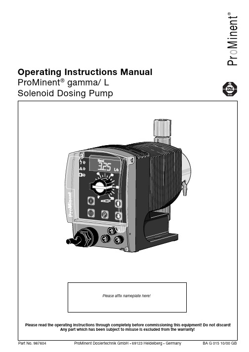
P r o M i n e n t®Operating Instructions Manual ProMinent ® gamma/ L Solenoid Dosing PumpPrintingPrinting:Operating Instructions ProMinent® gamma/ L© ProMinent Dosiertechnik GmbH, 1999Address:ProMinent Dosiertechnik GmbHIm Schuhmachergewann 5-11D-69123 HeidelbergPostfach 101760D-69007 Heidelberg*****************www.prominent.deSubject to technical alteration.Please fold out this page! ÈOperating-/Settings DiagramContinuous displayFunction DescriptionOperating modes Operating modes are selected using the MODE menu (depending upon identity code, someoperating modes may be absent)..“Analogue” operating mode: (Identity code, control variant: analogue current)The stroke rate is controlled via an analogue electrical signal via the “external control” terminal.Signal processing is pre-selected at the controller.“Manual” operating mode: (Identity code, control variant: manual, standard function)The stroke rate is controlled manually via the controller.“Contact” operating mode: (Identity code, control variant: external 1:1 / external with pulsecontrol)This operating mode offers the opportunity to make fine adjustments with small increase/decrease factors. Dosing can be activated by a pulse via the “external control” terminal or by asemiconductor element. With the “pulse control” option it is possible to pre-set a feed quantity(batch) or number of strokes (factor 0.01 to 99.99) via the control unit.“Batch” operating function: (identity code, control variant, external 1:1 / external with pulsecontrol)This operating mode offers the option of working with larger transfer factors (up to 65535).Metering can be triggered by pressing the P key or a pulse from the “external control” terminalvia a contact or semiconductor element. A batching quantity or number of strokes can be pre-selected via the control unit.Functions The following functions can be selected using the SET menu:“Calibrate” function:The gamma/ L can be operated in all operating modes including in calibrating mode. Thecorresponding continuous displays can show the actual feed quantity or the feed rate.Calibration is maintained within the stroke frequency range 0 - 180 strokes/ min. Calibration isalso maintained when a stroke frequency is altered up to ± 10 %.“Pressure level” function:It is possible to set different pressure levels.“Auxiliary frequency” function:It is possible to set a stroke rate in the SET menu, which may be activated via the “externalcontrol” terminal. This auxiliary frequency overrides all other pre-set stroke rate frequencies.“Flow” function:Stops the gamma/ L when the flow is insufficient. In the SET menu, the number of failed strokesis entered after which the pump will be turned off.The following functions are available as standard:“Float switch” function:Information on the liquid level in the feed chemical container is transmitted to the gamma/ L.This option requires the installation of a 2-stage float switch. This is connected to the “floatswitch” terminal.“Pause” function:The gamma/ L can be stopped by remote control via the “external control” terminal. The “pau-se” function operates only via the “external control” terminal.The following functions are activated by keystrokes:“Stop” function:The gamma/ L can be stopped by pressing the STOP/START key without disconnecting fromthe mains power supply.Function Description“Prime” function:Priming (short term feed at maximum frequency) is activated by pressing both arrow keys at thesame time.Optional relay The gamma/ L has two connection options.“Fault indicating relay” option:In the event of fault signals, warning signals or float switch activation signals, connects anelectrical circuit to trigger alarm sirens etc. The relay is retrofitted via an aperture in the powerend.“Fault indicating and pacing relay” option:Along with the fault indicating relay, the pacing relay produces an electrical impulse for everystroke. The relay is retrofitted via an aperture in the power end.Function and errorindicators The operating and error status is shown via the three LEDs and the “error” indicator on the LCD (see also section 12):LCD indicator If a fault occurs “error” will appear along with an additional fault warning.LED indicator Operating indicator (green)This indicator is lit as long as the gamma/ L is operating correctly.Warning indicator (yellow)This warning light appears if the gamma/ L electronics detect a situation that could lead to afault, e.g. “liquid levels low 1st stage”.Warning indicator (red)This warning light appears if a fault occurs, e.g. “liquid levels low 2nd stage”.Hierarchy of operating modes, functions and fault statusesThe different operating modes, functions and fault statuses each have a differing effect onwhether and how the gamma/ L functions. These effects are given below:1.Prime2.Fault, stop, pause3.Auxiliary frequency4.Manual, analogue, contact, batchto:1.“Prime” can be activated in any pump status (as long as it is operable)2.“Fault”, “stop” and “pause” stop all system parts up to “prime”.3.The stroke rate of the “auxiliary frequency” always overrides the existing operating strokerate.Commissioning / Operating8.2Diagrams for setting feed capacityGeneralS Open out the page showing the diagram of your pump type (see appendix).S Calculate the correction factor. Mark the operating pressure for your application in the dia-gram “correction factor depending upon operating pressure”.S Trace a line from this value vertically up to the curve and then horizontally left. Read off thecorrection factor.S Divide the required feed rate by the correction factor determined as above. Mark this value(l/h) on the “l/h” axis in the diagram “feed rate depending upon stroke length and strokerate”.S Trace a line horizontally from this value to the left. Trace a line from the intersection with thestraight line for the adjustable stroke frequencies vertically downwards to the “strokelength” axis.S Set the gamma/ L to one of the stroke frequencies determined in this way, and thecorresponding stroke length.The measurements for determining the feed rate for the following diagrams were carried outusing water and the correction factor was determined at a 70 % stroke length. Distribution ofthe feed rate across all material versions: -5 to +15 %.9OperatingThis section describes all operating options available to you when the gamma/ L is incontinuous display mode (no P key symbol in the LCD display).GUIDELINE•Open out the fold-out page following the title page fully! There you will find theoverviews “control elements and key functions” and “operating settings dia-gram”.•Look at the overview “continuous displays”. This page shows you which displaysare available in which operating mode, and which values are directly alterable inthe corresponding continuous displays.9.1Manual operationSet stroke length Stroke length is continually adjustable within a range of 0 - 100 %. The recommended strokelength range, which will practically guarantee technical reproducibility, is 30 - 100 % (SEK type:50 - 100 %).The following operating options are available via the different keys (see also figure on the nextpage):Stop/Start gamma/ L To stop gamma/ L: press STOP/START key.To start gamma/ L: press STOP/START key.Start batch Press the P key briefly in “batch” operating mode.Load factory settings Press the P key for 15 s to load factory calibration settings!Current settings will be deleted.Change to settings mode WeIf you press the P key for 2 s in any continuous display the gamma/ L will change to settingsmode (see section 7).If CODE 1 is set, the code must be entered after pressing the P key.Check adjustable values Each time you press the i key you will see a different continuous display. The number ofcontinuous displays depends upon the identity code, the selected operating mode and theconnected accessories.Change directlyalterable values To change a value (see below) directly in the corresponding continuous display, press one of thearrow keys until “set” appears in the LCD display. The delay has been programmed in to preventinadvertent changing of values.If CODE 2 has been set, this code must be entered after pressing the arrow key.Directly alterable values are as follows:。
丙酮安全技术说明书
丙酮安全技术说明书页码 1 / 10生效日期 28-Apr-2009修订日期 04-Apr-2019版本 4ACR17680根据G B /T 16483-2008, G B /T 17519-2013一 化学品及企业标识产品描述:丙酮Product Description:Acetone目录编号176800000; 176800010; 176800025; 176800026; 176800050; 176800051; 176800250;176805000同义字2-Propanone 化学文摘编号(C A S N o .)67-64-1分子式C3 H6 O供应者Acros Organics BVBAJanssen Pharmaceuticalaan 3a 2440 Geel, Belgium tel: 00800 14 57 52 11fax: 0800 96 656紧急电话号码4008215118电子邮件地址******************************推荐用途实验室化学品.不建议的用途无资料。
二 危险性概述物质或混合物的分类 严重眼损伤 / 眼刺激类别2特定目标器官毒性 - (单次接触类别3标签元素应急综述高度易燃液体和蒸气. 造成严重眼刺激. 可能引起昏睡或晕眩。
. 反复接触可能造成皮肤干燥或龟裂.易燃液体.类别2物理状态液体外观无色气味甜的警示语危险危害声明H225-高度易燃液体和蒸气H319-造成严重眼刺激H336-可能引起昏睡或眩晕防范说明预防P210-远离热源/火花/明火/热表面。
禁止吸烟P240-容器和接收设备接地/等势联接P241-使用防爆电气/通风/照明/设备P242-使用无火花工具P243-采取防止静电放电的措施P264-作业后彻底清洗脸部、手部和任何接触的皮肤P271-只能在室外或通风良好之处使用P280-戴防护手套/穿防护服/戴防护眼罩/戴防护面具。
Trigonox 311 3,3,5,7,7-Pentamethyl-1,2,4-trioxepan
Product Data SheetTrigonox 3113,3,5,7,7-Pentamethyl-1,2,4-trioxepaneTrigonox® 311 is a pure peroxide in liquid form.CAS number215877-64-8EINECS/ELINCS No. 455-560-2TSCA statuslisted on inventory Molecular weight 174.24Active oxygen content peroxide9.18%Concentration 8.72% min.SpecificationsAppearance Clear liquidAssay≥ 95.0 %ApplicationsTrigonox® 311 is a monofunctional peroxide which is used for the crosslinking of natural rubber and synthetic rubbers, as well as polyolefins. Safe processing temperature: 180°C (rheometer ts2 > 20 min.). Typical crosslinking temperature: 220°C (rheometer t90 about 12 min.).Thermal stabilityOrganic peroxides are thermally unstable substances, which may undergo self-accelerating decomposition. The lowest temperature at which self-accelerating decomposition of a substance in the original packaging may occur is the Self-Accelerating Decomposition Temperature (SADT). The SADT is determined on the basis of the Heat Accumulation Storage Test.SADT120°C (248°F)Method The Heat Accumulation Storage Test is a recognized test method for thedetermination of the SADT of organic peroxides (see Recommendations on theTransport of Dangerous Goods, Manual of Tests and Criteria - United Nations, NewYork and Geneva).StorageDue to the relatively unstable nature of organic peroxides a loss of quality can be detected over a period of time. To minimize the loss of quality, Nouryon recommends a maximum storage temperatureTs Max.40°C (104°F)Ts Min.15°C (59°F) to prevent crystallizationNote When stored under these recommended storage conditions, Trigonox® 311 willremain within the Nouryon specifications for a period of at least 12 months afterdelivery.Packaging and transportThe standard packaging is a 30-liter HDPE can (Nourytainer®) for 25 kg peroxide solution. Both packaging and transport meet the international regulations. For the availability of other packed quantities contact your Nouryon representative. Trigonox® 311 is classified as Organic peroxide type E; liquid, Division 5. 2; UN 3107.Safety and handlingKeep containers tightly closed. Store and handle Trigonox® 311 in a dry well-ventilated place away from sources of heat or ignition and direct sunlight. Never weigh out in the storage room. Avoid contact with reducing agents (e. g. amines), acids, alkalis and heavy metal compounds (e. g. accelerators, driers and metal soaps). Please refer to the Safety Data Sheet (SDS) for further information on the safe storage, use and handling of Trigonox® 311. This information should be thoroughly reviewed prior to acceptance of this product. The SDS is available at /sds-search.Major decomposition productsMethane, Acetone, Isopropyl acetate, 3-Hydroxy-1,3-dimethylbutyl acetate, 3-Methoxy-1,3-dimethylbutyl acetateAll information concerning this product and/or suggestions for handling and use contained herein are offered in good faith and are believed to be reliable.Nouryon, however, makes no warranty as to accuracy and/or sufficiency of such information and/or suggestions, as to the product's merchantability or fitness for any particular purpose, or that any suggested use will not infringe any patent. Nouryon does not accept any liability whatsoever arising out of the use of or reliance on this information, or out of the use or the performance of the product. Nothing contained herein shall be construed as granting or extending any license under any patent. Customer must determine for himself, by preliminary tests or otherwise, the suitability of this product for his purposes.The information contained herein supersedes all previously issued information on the subject matter covered. The customer may forward, distribute, and/or photocopy this document only if unaltered and complete, including all of its headers and footers, and should refrain from any unauthorized use. Don’t copythis document to a website.Trigonox® and Nourytainer are registered trademarks of Nouryon Functional Chemicals B.V. or affiliates in one or more territories.Contact UsPolymer Specialties Americas************************Polymer Specialties Europe, Middle East, India and Africa*************************Polymer Specialties Asia Pacific************************2022-6-30© 2022Polymer crosslinking Trigonox 311。
三(2-甲氧基甲氧基乙基)胺氧化物

三(2-甲氧基甲氧基乙基)胺氧化物下载提示:该文档是本店铺精心编制而成的,希望大家下载后,能够帮助大家解决实际问题。
文档下载后可定制修改,请根据实际需要进行调整和使用,谢谢!本店铺为大家提供各种类型的实用资料,如教育随笔、日记赏析、句子摘抄、古诗大全、经典美文、话题作文、工作总结、词语解析、文案摘录、其他资料等等,想了解不同资料格式和写法,敬请关注!Download tips: This document is carefully compiled by this editor. I hope that after you download it, it can help you solve practical problems. The document can be customized and modified after downloading, please adjust and use it according to actual needs, thank you! In addition, this shop provides you with various types of practical materials, such as educational essays, diary appreciation, sentence excerpts, ancient poems, classic articles, topic composition, work summary, word parsing, copy excerpts, other materials and so on, want to know different data formats and writing methods, please pay attention!三(2甲氧基甲氧基乙基)胺氧化物是一种常用的有机化合物,具有较强的氧化性和活性。
类普鲁士蓝的制备及其活化PMS降解双酚S
化工进展Chemical Industry and Engineering Progress2023 年第 42 卷第 12 期类普鲁士蓝的制备及其活化PMS 降解双酚S杨有威1,2,3,曾亦婷1,2,郭昌胜3,罗玉霞1,2,高艳1,2,王春英1,2(1 矿冶环境污染防控江西省重点实验室,江西 赣州 341000;2 江西理工大学资源与环境工程学院, 江西 赣州341000;3 中国环境科学研究院环境基准与风险评估国家重点实验室, 北京 100012)摘要:通过简单共沉淀法合成了类普鲁士蓝化合物(CoFe-PBA ),用于活化过一硫酸盐(PMS )降解有机污染物双酚S (BPS )。
使用扫描电镜、X 射线衍射、X 射线光电子能谱等手段对CoFe-PBA 进行表征,结果表明CoFe-PBA 由紧密结合的Co 3[Fe(CN)6]2构成,为纳米级,表面均匀分布着C 、Fe 、Co 、O 元素,具有丰富的活性位点。
催化剂投加量300mg/L 、PMS 投加量400mg/L 、pH=5.89条件下,CoFe-PBA/PMS 降解体系40min 内去除73.77%的BPS ,对酸性和共存离子(SO 42−、NO 3−和Cl −)敏感,碱性环境能促进PMS 快速活化,重复实验显示该体系具有良好稳定性,使用4次后仅下降26.70%,活化性能优于其他材料。
机理分析表明,CoFe-PBA 与PMS 相互作用,作用过程中改变了金属位点价态,发生电子转移,产生各种活性物质降解BPS ,其主要作用活性物种为1O 2;产物分析表明,在CoFe-PBA 活化PMS 系统中,BPS 可历经三种路径最终转化为开环产物及CO 2和H 2O 。
本研究通过低耗能、低成本、快速简易的方法制备CoFe-PBA ,可为活化PMS 绿色降解BPS 提供思路。
关键词:双酚S ;过硫酸盐活化;类普鲁士蓝;过渡金属中图分类号:X703 文献标志码:A 文章编号:1000-6613(2023)12-6676-11Preparation of Prussian blue and its activation of PMS fordegrading bisphenol SYANG Youwei 1,2,3,4,ZENG Yiting 1,2,GUO Changsheng 3,LUO Yuxia 1,2,GAO Yan 1,2,WANG Chunying 1,2(1 Jiangxi Provincial Key Laboratory of Environmental Pollution Prevention and Control in Mining and Metallurgy,Ganzhou 341000, Jiangxi, China; 2 School of Resources and Environmental Engineering, Jiangxi University of Science and Technology, Ganzhou 341000, Jiangxi, China; 3 State Key Laboratory of Environmental Criteria and Risk Assessment,Chinese Research Academy of Environmental Sciences, Beijing 100012, China)Abstract: A Prussian blue-like compound (CoFe-PBA) was synthesized by a simple co -precipitation method for activating permonosulfate (PMS) to degrade organic pollutant bisphenol S (BPS). CoFe-PBA showed high activity on the removal of bisphenol S from activated PMS. Scanning electron microscopy, X-ray diffraction, and X-ray photoelectron spectroscopy were used to characterize CoFe-PBA. The results showed that CoFe-PBA was composed of Co 3[Fe(CN)6]2, which was in nanometer scale. The surface was evenly distributed with C, Fe, Co, O elements, with abundant active sites. Under the conditions of catalyst研究开发DOI :10.16085/j.issn.1000-6613.2023-0803收稿日期:2023-05-15;修改稿日期:2023-07-21。
IEC 60079-26.2006

Disclosure to Promote the Right To InformationWhereas the Parliament of India has set out to provide a practical regime of right to information for citizens to secure access to information under the control of public authorities, in order to promote transparency and accountability in the working of every public authority, and whereas the attached publication of the Bureau of Indian Standards is of particular interest to the public, particularly disadvantaged communities and those engaged in the pursuit of education and knowledge, the attached public safety standard is made available to promote the timely dissemination of this information in an accurate manner to the public. इंटरनेटमानक“!ान$एकन'भारतका+नम-ण”Satyanarayan Gangaram Pitroda“Invent a New India Using Knowledge”“प0रा1कोछोडन'5तरफ”Jawaharlal Nehru“Step Out From the Old to the New”“जान1 का अ+धकार, जी1 का अ+धकार”Mazdoor Kisan Shakti Sangathan“The Right to Information, The Right to Live”“!ानएकऐसाखजाना>जोकभीच0रायानहB जासकताह”Bhart ṛhari—N īti śatakam“Knowledge is such a treasure which cannot be stolen”ge””हIS/IEC 60079-26 (2006): Electrical apparatus for explosive gas atmospheres, Part 26: Equipment With Equipment Protection Level (EPL) Ga [ETD 22: Electrical Apparatus for Explosive Atmosphere]IS/IEC 60079-26 : 2006Hkkjrh; ekudfoLiQks V h i;kZ o j.kHkkx 26 miLdj lq j{kk Lrj (bZ i h,y) th, okys miLdjIndian StandardEXPLOSIVE ATMOSPHERESPART 26 EQUIPMENT WITH EQUIPMENT PROTECTION LEVEL (EPL) GaICS 29.260.20© BIS 2013B U R E A U O F I N D I A N S T A N D A R D SMANAK BHAVAN, 9 BAHADUR SHAH ZAFAR MARGNEW DELHI 110002February 2013 Price Group 8Electrical Apparatus for Explosive Atmospheres Sectional Committee, ETD 22NATIONAL FOREWORDThis Indian Standard (Part 26) which is identical with IEC 60079-26 : 2006 ‘Explosive atmospheres — Part 26: Equipment with equipment protection level (EPL) Ga’ issued by the International Electrotechnical Commission (IEC) was adopted by the Bureau of Indian Standards on the recommendation of the Electrical Apparatus for Explosive Atmospheres Sectional Committee and approval of the Electrotechnical Division Council.The text of IEC Standard has been approved as suitable for publication as an Indian Standard without deviations. Certain conventions are, however, not identical to those used in Indian Standards. Attention is particularly drawn to the following:a)Wherever the words ‘International Standard’ appear referring to this standard, they should beread as ‘Indian Standard’.b)Comma (,) has been used as a decimal marker while in Indian Standards, the current practiceis to use a point (.) as the decimal marker.In this adopted standard, references appear to certain International Standards for which Indian Standards also exist. The corresponding Indian Standards, which are to be substituted in their respective places are listed below along with their degree of equivalence for the editions indicated: International Standard Corresponding Indian Standard Degree of EquivalenceIEC 60079-0 : 2004 Electrical apparatus for explosive gas atmospheres — Part 0: General requirementsIEC 60079-1 Electrical apparatus for explosive gas atmospheres —Part1: Flameproof enclosures “d”IEC 60079-10 Electrical apparatus for explosive gas atmospheres —Part10: Classification of hazardous areasIEC 60079-11 Explosive atmospheres — Part 11: Equipment protection by intrinsic safety “i”IEC 60079-18 Electrical apparatus for explosive gas atmospheres —Part18:Construction,test and marking of type of protection encapsulation “m” electrical apparatus IS/IEC 60079-0 : 2007 Explosiveatmospheres: Part 0 Equipment —General requirementsIS/IEC 60079-1 : 2007 Explosiveatmospheres: Part 1 Equipmentprotection by flameproof enclosures“d”IS 5572 : 2009 Classification ofhazardous areas (other than mines)having flammable gases and vapoursfor electrical installationIS/IEC 60079-11 : 2006 Explosiveatmospheres: Part 11 Equipmentprotection by intrinsic safety “i”IS/IEC 60079-18 : 2009 Explosiveatmospheres: Part 18 Equipmentprotection by encapsulation “m”(firstrevision)Identical toIEC 60079-0 : 2007Identical toIEC 60079-1 : 2007ModifiedIdentical toIEC 60079-11 : 2006Identical toIEC 60079-18 : 2009(Continued on third cover)The technical committee has reviewed the provision of the following International Standard referred in this adopted standard and has decided that it is acceptable for use in conjunction with this standard: International Standard TitleIEC 60695-11-10Fire hazard testing — Part 11-10: Test flames — 50 W horizontal and vertical flame test methodsIS/IEC 60079-26 : 2006Indian StandardEXPLOSIVE ATMOSPHERESPART 26 EQUIPMENT WITH EQUIPMENT PROTECTION LEVEL (EPL) Ga1 ScopeThis part of IEC 60079 specifies the particular requirements for construction, test and marking for electrical equipment that provides equipment protection level (EPL) Ga. This electrical equipment, within the operational parameters specified by the manufacturer, ensures a very high level of protection that includes rare faults related to the equipment or two faults occurring independently of each other.NOTE 1 A malfunction may result from a failure of the component parts of the electrical equipment or from anticipated externally applied influences. Two independent malfunctions which may occur more frequently and which, separately, would not create an ignition hazard but which, in combination, could create a potential ignition hazard, should be regarded as occurring together to form a rare fault.NOTE 2 This electrical equipment is intended for use in zone 0 hazardous areas, in which explosive gas atmospheres caused by mixtures of air and gases, vapours or mists under normal atmospheric conditions are present continuously, for long periods or frequently.This standard also applies to equipment mounted across a boundary where different protection levels may be required.EXAMPLE: In the wall of a storage vessel containing zone 0 with an ambient defined as zone 1.This standard also applies to equipment installed in an area requiring a lower protection level, but electrically connected to equipment with equipment protection level (EPL) Ga (associated apparatus).This standard supplements the general requirements in IEC 60079-0 and the requirements of the standardized types of protection, in accordance with the IEC 60079 series, to adapt the level of safety provided by those standards in order to provide EPL Ga.NOTE 3 In designing equipment for operation in explosive gas atmospheres under conditions other than the atmospheric conditions given in IEC 60079-0, this standard may be used as a guide. However, additional testing is recommended related specifically to the intended conditions of use. This is particularly important when the types of protection ‘Flameproof enclosures’ (IEC 60079-1) and ‘Intrinsic safety’ (IEC 60079-11) are applied.NOTE 4 The classification of hazardous areas in zones is defined in IEC 60079-10.NOTE 5 There may be other non-electrical sources of ignition (for example ultrasonic, optical or ionizing radiation) that are not addressed by this standard; these should also be taken into consideration (see, for example, EN 1127-1). NOTE 6This concept provides equipment protection level (EPL) Ga. For further information, see Annex A.IS/IEC 60079-26 : 20062 Normative referencesThe following referenced documents are indispensable for the application of this document. For dated references, only the edition cited applies. For undated references, the latest edition of the referenced document (including any amendments) applies.IEC 60079-0:2004, Electrical apparatus for explosive gas atmospheres – Part 0: General requirementsIEC 60079-1, Electrical apparatus for explosive gas atmospheres – Part 1: Flameproof enclosures "d"IEC 60079-10, Electrical apparatus for explosive gas atmospheres – Part 10: Classification of hazardous areasIEC 60079-11, Explosive atmospheres – Part 11: Equipment protection by intrinsic safety "i"IEC 60079-18, Electrical apparatus for explosive gas atmospheres – Part 18: Construction, test and marking of type of protection encapsulation "m" electrical apparatusIEC 60695-11-10, Fire hazard testing – Part 11-10: Test flames – 50 W horizontal and vertical flame test methods3 Terms and definitionsFor the purposes of this document, the terms and definitions given in IEC 60079-0 apply, together with the following abbreviation.NOTE Additional definitions applicable to explosive atmospheres can be found in IEC 60050-426.3.1EPLabbreviation of equipment protection level as defined in Annex A4 Requirements for design and construction4.1 GeneralThe equipment shall comply with the requirements of 4.2 for the electrical circuits and with the requirements of 4.3 to 4.6 for mechanical and electrostatic ignition hazards.4.2 Protection measures against ignition hazards of the electrical circuits4.2.1 GeneralThe equipment shall comply with the requirements of eithera) 4.2.2 or 4.2.3 in the event of two faults occurring independently of each other in a singleequipment means of protection; orb) 4.2.4 or 4.2.5 in the event of a failure of one equipment means of protection, by theprovision of a second independent means of protection.IS/IEC 60079-26 : 2006 Electrical connections and permanently connected cables of the equipment sited within an area requiring EPL Ga equipment shall comply with the same level of protection required by this standard, for example an Ex “e” cable containing non-Ex ia circuits additionally protected by a flameproof conduit or an Ex “e” cable provided with an earth leakage protection.NOTE 1 Detailed cable and installation requirements for non-intrinsically safe circuits providing EPL Ga are in consideration in IEC 60079-14.NOTE 2 Because of ignition hazards which can arise from faults and/or transient circulating currents in the potential equalization system, galvanic isolation in the power and signal connections to the equipment according to 4.2.2, 4.2.3 and 4.2.4 is preferred. Consideration should also be given to minimize the effect of transient fault currents in the potential equalization network by the use of electrical protection equipment such as sensitive earth leakage monitors.4.2.2 Intrinsic safety as a sole means of protectionIntrinsically safe electrical equipment providing EPL Ga and intrinsically safe electrical circuits of associated apparatus entering an area requiring EPL Ga shall comply with the requirements of IEC 60079-11, intrinsic safety “ia”.NOTE Intrinsic safety “ib” in accordance with IEC 60079-11 may be considered as one of two independent means of protection according to 4.2.4.4.2.3 Encapsulation as a sole means of protectionElectrical equipment which is protected by encapsulation providing EPL Ga shall comply with the requirements of IEC 60079-18, encapsulation “ma”.NOTE Encapsulation “mb” in accordance with IEC 60079-18 may be considered as one of two independent means of protection according to 4.2.4.4.2.4 Application of two independent types of protection providing EPL GbElectrical equipment shall comply with the requirements of two independent types of protection that provide EPL Gb. If one type of protection fails, the other type of protection shall continue to function. The independent types of protection shall not have a common mode of failure, except as specified in this clause.An example of a common mode failure is if an Ex “d” enclosure with arcing contacts inside it is used inside an Ex “e” enclosure. If the Ex “d” enclosure is compromised, then arcing inside the enclosure will also compromise the Ex “e” enclosure.NOTE Combined types of protection providing EPL Gb should depend on different physical protection principles. For example the combination of Ex “d” and Ex “q” both depend on the avoidance of flame propagation and may not be useful in combination. In practice, some combinations may not be useful, for example the combination of oil and powder filling.Where combined types of protection are used, it shall be possible for each type of protection to be tested individually (see 5.1).Both types of protection shall be assessed using the most arduous fault condition of the other type of protection. When combining intrinsic safety, type of protection “ib”, with other types of protection, the second type of protection shall be assessed, with the most arduous fault condition applied to the intrinsically safe circuit.When using two types of protection, which rely both on the same parameter (for example, the creepage distance combining Ex “ib” with Ex “e”), the most stringent requirement of both types of protection shall be applied.IS/IEC 60079-26 : 2006If two types of protection are combined which both rely on the enclosure, one of the following shall be met:a) if two enclosures are used (one totally enclosed within the other), each enclosure shallcomply with the requirements of the respective type of protection; orb) if only one enclosure is used, the enclosure and the cable glands shall meet the impact testrequirements of 26.4.2 of IEC 60079-0, using the group I values.Examples of combinations of two independent types of protection are as follows:– inductive transmitters (for example proximity switches, electrical position sensors) with intrinsic safety “ib” enclosed by encapsulation “mb”. The connections to intrinsically safe “ib” circuits can be protected by the increased safety “e”;– a lamp with the bulb designed as increased safety “e”, the lamp circuit with the switch as intrinsic safety “ib”. These components may be incorporated in a flameproof enclosure “d”; – measuring transducers with intrinsic safety “ib” and a flameproof enclosure “d”;– equipment with electrical circuits of intrinsic safety “ib”, additionally protected by a powder filling “q”;– electromagnetic valves with encapsulation “mb”, enclosed by a flameproof enclosure “d”;– increased safety “e”, with pressurized equipment “px”.4.2.5 Application of a type of protection providing EPL Gb and a separation element 4.2.5.1 GeneralEquipment which is mounted through or forming part of the boundary wall to an area requiring EPL Ga and containing electrical circuits which do not comply with protection level Ga shall comply at least with one of the types of protection providing EPL Gb. Additionally, they shall contain a mechanical separation element as part of the equipment to seal off the electrical circuits of the equipment from the area requiring EPL Ga.If the type of protection fails, the separation element shalla) prevent flame propagation through the equipment into the area requiring EPL Ga,b) maintain its safety characteristics,c) not be heated above the temperature class of the equipment.Separation elements consist of a partition wall, possibly combined with a flameproof joint or an air gap with natural ventilation.4.2.5.2 PartitionwallsPartition walls shall be constructed of eithera) corrosion-resistant metals, glass or ceramics, which are specified in the manufacturer’sdocumentation; orb) other materials as long as the same level of safety can be demonstrated. In this case, X-marking or an advisory marking in accordance with 29.2 of IEC 60079-0 shall be applied and the certificate shall clearly specify the material and its thermal and mechanical properties to enable the user to confirm the suitability for the particular application.If the wall thickness is less than 1 mm, the equipment shall be marked with an “X” or an advisory marking according to 29.2 of IEC 60079-0 with a special condition for safe use that the material shall not be subject to environmental conditions which might adversely affect the partition wall. If the partition wall is under constant vibrational stress (for example vibrating membranes), the minimum endurance limit at maximum amplitude shall be defined in the documentation.NOTE 1 A wall thickness less than 1 mm is only permitted in combination with intrinsic safety “ib”, or a flameproof joint or natural ventilation, see 4.2.5.3.NOTE 2 For glass or ceramics, a minimum thickness of 1/10 of the diameter/maximum dimension but not less than 1 mm is recommended.In addition to the requirements of 4.2.5.1 to 4.2.5.3, metallic partition walls with a thickness ≥ 1 mm may be provided with suitable conductor bushings (see Figure 1). To avoid a critical concentration of explosive gas atmosphere diffusing from the area requiring EPL Ga into the enclosure containing the electrical circuits, the leakage rate through the bushing shall be low compared to the leakage rate from the enclosure into the free atmosphere. This can be achieved, for example, by using a glass or ceramic bushing as shown in Figure 1.NOTE 3 Using a standard enclosure with an IP67 rating according to IEC 60529, a bushing with a leakage rate equivalent to a helium-leakage rate less than 10-2 Pa ×l/s (10–4 mbar ×l/s) at a pressure difference of 105 Pa (1 bar) is sufficient. Ex “ia” circuit Partition wall(≥1 mm) Electrical apparatusArearequiringEPL GaFigure 1 – Example of a partition wall with a conductor bushingbeing considered gas diffusion tight4.2.5.3 Requirements depending on the thickness of the partition wallThe combinations of separation elements and additional protective measures depend on the wall thickness, t , of the partition wall as described below and shown in Table 1:i) for homogeneous partition walls with a thickness ≥3 mm, no additional protection measuresare required;IS/IEC 60079-26 : 2006ii) for homogeneous partition walls with a thickness of 3 mm > t≥ 1 mm,one EPL Gb type of protection is required (see example a) of Table 1). A homogeneous part of the enclosure of an equipment with a EPL Gb type of protection may form the partition wall, even for types of protection which rely on the enclosure, provided the equipment does not contain an ignition capable source, for example exposed contacts (see example a) of Table 1). If the equipment contains a source of ignition in normal operation, additionally either a flameproof joint (example b) of Table 1) or a ventilated air gap (example c) of Table 1) is required;iii) behind partition walls of 1 mm > t≥ 0,2 mm, one of the following protective measures isrequired:−type of protection intrinsic safety “ib” according to IEC 60079-11 (example a) of Table 1); or−one EPL Gb type of protection in combination with a flameproof joint (example b) of Table 1); or−one EPL Gb type of protection in combination with a ventilated air-gap and a flameproof joint (example c) of Table 1);iv) for a partition wall with t < 0,2 mm (for example membranes), a flameproof joint and one EPL Gb type of protection are required (example b) of Table 1). If the equipment contains a source of ignition in normal operation (for example by exposed contacts), additionally a ventilated air gap is required (example c) of Table 1).NOTE In the context of this clause, ‘homogeneous’ means a membrane constructed of a single piece of material without any insertions such as feed-thrus, bushings.Table 1 – Separation elementsArearequiringEPL GaPartitionwallArearequiringEPL GaPartitionwall aTable 1 (continued) Flameproof joint and partition wall are exchangeable in sequence of order.4.2.5.4 Partition wall combined with a flameproof jointJoints supplementing partition walls shall comply with eithera) the requirements in IEC 60079-1; orNOTE 1 To determine the joint characteristics, the free volume of the enclosure containing the electrical circuits should be considered.b) a construction, where the same level of safety as for a) can be demonstrated.NOTE 2 For example, a cylindrical PTFE-bushing pressed form-fit into a metallic enclosure at a length ≥40 mm. A permanently compressed joint with a length of at least 17 mm is also suitable (for example using a conical PTFE-bushing compressed by a spring).Non-metallic components in separation elements shall meet the requirements of IEC 60695-11-10, flammability category V-0 and have a chemical resistivity equivalent, for example to that of glass, ceramics, non-regenerated PTFE or epoxy resin for petrol applications. The materials of the separation element and its mechanical and thermal stress limits shall be clearly defined in the documentation to enable the user to confirm their suitability for the particular application.4.2.5.5 Partition wall combined with an airgap with natural ventilationThe ventilation shall ensure that under the most onerous process conditions specified by the manufacturer and the anticipated leakages, an accumulation of flammable materials in the equipment is prevented. Under atmospheric process conditions, the ventilation is valid for all gases, vapours and mists, if the length of the air-gap is ≥10 mm and the effective perforation in the circumference is at least 50 %. In addition to the requirements of 4.2.5.1 to 4.2.5.3, metallic partition walls with a thickness ≥1 mm and a suitable air-gap may be provided, for example with a cylindrical flameproof shaft joint according to IEC 60079-1, see Figure 2. In this case, the ventilation air gap shall have a minimum length of 10 mm or a length equal to the diameter of the shaft, whichever is greater.Area requiringEPL Ga Partitionwall aPartition wall(≥1 mm) Area requiringEPL Ga Shafta Required for sufficient ventilation. NOTE 1 The cylindrical shaft joint inside the partition wall as shown in Figure 2 is not a supplementing joint as referred to in 4.2.5.4.NOTE 2 The electrical equipment should be selected in accordance with the appropriate gas group.Figure 2 – Example of a separation element with a cylindrical shaft jointand natural ventilation4.3 Equipment with moving parts4.3.1 Frictional heatingIf the equipment contains moving parts, temperature rise due to frictional heating may occur under normal operation or fault condition. It shall be taken into consideration when determining the maximum surface temperature.4.3.2 Damage arising from failure of moving partsIn case of a failure of moving parts, the types of protection shall not be adversely affected.4.3.3 Light metalsOperational friction or impact between equipment parts made of light metals or their alloys (with concentrations above the limits given in IEC 60079-0) with equipment parts made of iron/steel is not permitted. Operational friction or impact between two light metals is permitted. NOTE Light metals are for example aluminium, magnesium, titanium or zirconium.4.4 Isolated conductive componentsIsolated conductive components on the surface of the equipment shall be bonded to ground, except where they cannot be charged to an ignition capable level as demonstrated by the charging test procedure of IEC 60079-0.4.5 Non-conductive enclosures and accessible non-conductive components4.5.1 GeneralPrecautions shall be taken to ensure that the risk of ignition from electrostatic discharge is reduced to a negligible level, particularly since equipment providing EPL Ga may be applied directly in the process and non-conductive surfaces may be charged by the flow of non-conductive media (for example in stirring vessels or pipes).Therefore, the accessible chargeable surfaces of the equipment shall comply with the requirements of 7.3 of IEC 60079-0 or one of the following:a) limitation of the size of chargeable non-conductive surfaces – see 4.5.2;b) limitation of the thickness of chargeable non-conductive layers – see 4.5.3;c) provision of a conductive coating – see 4.5.4.If none of these requirements can be complied with, X-marking or an advisory marking in accordance with 29.2 of IEC 60079-0 shall be applied and the certificate shall contain special conditions for safe use to enable the user to decide on the suitability of the equipment for the particular application.4.5.2 Limitation of the size of chargeable non-conductive surfacesThe projection of the chargeable non-conductive surface shall be limited to the values given in in Table 4 of IEC 60079-0 for zone 0 (EPL Ga). In the case of long parts with non-conductive surfaces, such as tubes, bars, cables or ropes, independent of their length, the diameters or widths shall not exceeda) 3 mm for equipment of groups IIA and IIB;b) 1 mm for equipment of group IIC.4.5.3 Limitation of the thickness of chargeable non-conductive layersWhere a non-conductive layer covers a bonded conductive surface, the thickness of that layer shall not exceeda) 2 mm for equipment of group IIA, IIB;b) 0,2 mm for equipment of group IIC.The bonded conductive surface may be formed by a wire mesh with a mesh area as defined in IEC 60079-0, Table 4 for zone 0 (EPL Ga).NOTE 1 Cables with a protective covering over a screen may comply.NOTE 2 It should, however, be noted that in the presence of a very efficient charge generating mechanism propagating brush discharges could occur.4.5.4 Provision of a conductive coatingNon-conductive surfaces may be covered with a bonded durable conductive coating. The resistance between coating and the point of bond shall not exceed 1 GΩ.The resistance shall be measured in accordance with 26.13 of IEC 60079-0 using a 1 cm2 electrode at the worst case position of the surface and the point of bond.X-marking or an advisory marking in accordance with 29.2 of IEC 60079-0 shall be applied and the certificate shall advise on the use of the bonding connection (if separately accessible to the user and not an integral part of the equipment) and provide information to enable the user to decide on the durability of the coating material with respect to the environmental conditions (see Clause 7).NOTE The requirements of 4.5 will be deleted after incorporation in IEC 60079-0.connection4.6 ProcessIf the equipment is mounted across the boundary wall between an area requiring EPL Ga and a less hazardous area, the construction shall ensure that eithera) explosive gas atmospheres cannot be released from an area requiring EPL Ga creating anexplosive atmosphere in the surrounding area; orb) that in case of an ignition of an explosive gas atmosphere in the surrounding area there isno flame propagation into the area requiring EPL Ga.The equipment shall be designed to allow installation in a manner that will result in a sufficiently tight joint (IP67) or flameproof joint (IEC 60079-1) between the less hazardous area and zone 0.NOTE 1 For example equipment with an integrated separation element according to 4.2.5 or with an IP67 rating according to IEC 60529 between zone 0 and the less hazardous area are suitable.Process connections shall comply with an international, or equivalent national, standard.NOTE 2 Examples of process connections which are considered as suitable include:a) gas-tight standardized industry flange;b) gas-tight standardized tube fitting;c) gas-tight standardized thread connection.NOTE 3 If, for functional purposes, an opening is required in the boundary wall of zone 0 (for example chemical sampling at the open nozzle, rope guide for probes), instructions for the user are required in the documentation referring to the risk of flammable gas release and flame entrance.5 Type tests5.1 Standardized types of protectionEquipment in which EPL Gb types of protection are applied shall be submitted to type verifications and tests as specified in the respective standards. If the combination of two zone 1 types of protection according to 4.2.4 are applied, both types of protection shall be tested independently.elements5.2 SeparationSeparation elements in accordance with 4.2.5 shall be tested in such a way that the operational parameters (for example pressure or temperature limits) stated by the manufacturer are verified.evaluation5.3 TemperatureFor the temperature evaluation, two independent faults shall be taken into account.。
岛津应对2010版药典--标准

新增--中药指纹图谱(1)--LC与GC法
中药制剂中引入指纹图谱: -----(详细规定各个参数及相似度)
1、复方丹参滴丸 ----- HPLC-等度,8个特征峰,相似度不低于0.9 2、天舒胶囊 ----- HPLC-梯度, 7个特征峰,相似度不低于0.85 3、注射用双黄连 ----- HPLC-梯度,7个特征峰,相似度不低于0.9; 4、桂枝茯苓胶囊 ----- HPLC-梯度,8个特征峰,相似度不低于0.9; 5、诺迪康胶囊 ----- HPLC-梯度,相似度不低于0.9; 6、腰痛宁胶囊 ----- HPLC-梯度,相似度不低于0.9;
13
部分值得关注点(6)
总有机碳测定法(TOC测定仪)进入药典正文,被用于纯化水、注射用 水等标准中; 针对药物特点,含量测定采用了专属性更强的检查方法。 例如:TLC与UV检测方法大量改进为HPLC法定量;
例如:HPLC法梯度分析条件大量替代原有等度分析条件,某些中药材的定量更 是引入LCMS方法; 例如:液相五种检测器均出现在2010版中国药典中。
2010版药典
2010年版《中国药典》分为三部出版,一部为 中药,二部为化学药,三部为生物制品。 2010年版《中国药典》收载品种4567余种,其中 新增1386种,原有药典品种系统性修订提高的标 准2237个,基本覆盖国家基本药物目录品种和国 家医疗保险目录品种。
4
一部正文
药典一部收载药材及饮片、植物油脂和提取物、 成方和单味制剂共2165个,比05年版1146个增加 约1019个。 其中药材和饮片:新增药材59,新增饮片355, 共新增414,修订365 植物油脂和提取物标准:新增27,修订14 中成药标准:新增549,修订233
17
丹参滴丸HPLC指纹图谱
西班牙Comspain公司的磷复肥生产设备
最理 想 的流态 化 。因 此 , 不仅 要 仔 细 考虑 气 流 的设 计 , 足所 要 求 的 工 作设 备 尺 寸 大 小 , 且 气 体 散 满 而 布板 的开 孔 、 层 高度 以 及 加 热 、 却 的方 法 也 是 床 冷
很重 要 的。
料机 、 式 输 送 机 、 仓 、 车 机 等 ) 二 是 在 20 带 料 卸 ; 09
物 料混 和 。
体 而 形 成 的气 流 柱 中时 , 体 将 穿 透 颗 粒 群 , 使 气 并
颗 粒之 间互 相分 离 。随着 气 流 的增 大 , 粒分 离 的 颗
许 多 流化床成 套 设 备 主要 用 于 干燥 , 用 的热 所 空 气 由蒸 汽 加 热 或 者 用 燃 油 加 热 器 加 热 。对 于 可
格, 以提供 在各操 作 阶段 最佳 的流 化 速 度 。流 化气
体 的温度 在每个 强 制 通 风分 隔 里 可 以改 变 , 后 的 最
一
具有 特色 的几项 技 术作 一些 考察 。
格 可 以是 冷却 区 , 使产 物在低 温下 出料 。 流化 物料 的性 质 很 像 液 体 。加 工 产 物 从 可 调
热能 力 。 当颗 粒 的搅 动 和 鼓 泡 的大 小 平 衡 时 达 到
需成 套设 备 和装卸 设备 的合 同 , 以及 为 Ma ae ’dn磷
酸盐 公 司 ( 特 阿拉 伯 矿 业 公 司 的子 公 司 ) 建磷 沙 在 酸厂 和磷 矿装 卸提 供所 需 设 备 ( 料 机 、 取 堆垛 机 、 耙
20 09年 , 班 牙 C m pi 司 在 其 肥 料 工 业 西 o san公 设 备业 务 名 录 中又 增 加 了 4项 。一 是 与 It s ne a工 c
废水处理硝酸盐异化还原与厌氧氨氧化
化工进展Chemical Industry and Engineering Progress2024 年第 43 卷第 3 期废水处理硝酸盐异化还原与厌氧氨氧化/反硝化耦合工艺构建赵瑞强1,2,周鑫1,2,牛冰心1,2(1 太原理工大学环境科学与工程学院,山西 晋中 030600;2 山西省市政工程研究生教育创新中心,山西 晋中 030600)摘要:采用厌氧膨胀颗粒污泥床反应器(EGSB )处理含COD 、氨氮和硝氮的模拟废水,旨在高浓度有机废水处理系统中快速构建厌氧氨氧化(Anammox )运行工艺。
通过接种少量Anammox 污泥和逐步提高氨氮浓度的操作方式,在连续运行58d 后,系统成功启动Anammox 反应,此时的总氮和COD 去除率稳定在97%和98%以上。
物料衡算显示,Anammox 反应途径对氮的去除贡献逐渐增加,硝酸盐异化还原(DNRA )耦合Anammox 和反硝化共同促进了系统的同步脱氮除碳。
对微生物群落分析发现,Candidatus Kuenenia 相对丰度由0.27%快速升高至35.87%,DNRA 菌(Ignavibacterium 、Thermogutta )及反硝化菌(Azospira 、Gp 3)在体系内共存。
通过基因注释法,检测出了Anammox 、DNRA 、硝酸盐还原及亚硝酸盐还原关键基因。
运行过程中,颗粒污泥颜色变红且粒径增大;胞外聚合物(EPS )分析表明多糖(PS )和蛋白质(PN )含量增加而PN/PS 下降;三维荧光光谱发现腐殖酸类物质增多。
研究结果为高浓度有机含氮废水高效处理提供了一种新的工艺途径。
关键词:膨胀颗粒污泥床反应器;高浓度有机含氮废水;硝酸盐异化还原;厌氧氨氧化;反硝化;耦合脱氮中图分类号:X703 文献标志码:A 文章编号:1000-6613(2024)03-1593-13Construction of a coupled process integrating dissimilatory nitrate reduction and anaerobic ammonia oxidation/denitrification forwastewater treatmentZHAO Ruiqiang 1,2,ZHOU Xin 1,2,NIU Bingxin 1,2(1 College of Environmental Science and Engineering, Taiyuan University of Technology, Jinzhong 030600, Shanxi, China;2Innovation Center for Postgraduate Education in Municipal Engineering of Shanxi, Jinzhong 030600, Shanxi, China)Abstract: An anaerobic expanded granular sludge bed reactor (EGSB) was used to treat simulated wastewater containing COD, ammonia and nitrate nitrogen to rapidly establish anaerobic ammonium oxidation (Anammox) process in a high-concentration organic wastewater treatment system. By inoculating a small amount of Anammox sludge and gradually increasing the concentration of ammonia nitrogen, the system successfully started the Anammox reaction after 58d of continuous operation, at which the total nitrogen and COD removal efficiencies were stable to over 97% and 98%, respectively.Mass balance showed that the contribution of Anammox reaction pathway to nitrogen removal gradually increased, and dissimilatory nitrate reduction (DNRA) coupled with Anammox and denitrification研究开发DOI :10.16085/j.issn.1000-6613.2023-0449收稿日期:2023-03-23;修改稿日期:2023-05-12。
改性柿子生物吸附剂对铜和铅的吸附性能
改性柿子生物吸附剂对铜和铅的吸附性能郭学益;公琪琪;梁沙;田庆华;肖彩梅【摘要】The persimmon powder was used as raw material to prepare two persimmon biosorbents SPP and HPP by chemical modification withH2SO4 and HNO3, respectively. The adsorption behaviors of Cu2+ andPb2+ in aqueous solutions on two persimmon biosorbents were investigated. The effects of solution pH, solid-liquid ratio, temperature, adsorption time and metal ion concentration were considered. The results show that the adsorption process of SPP and HPP can be well described by pseudo-second order kinetic equation. The fitting effect of equilibrium isotherms follows Langmuir equation better than that of the Freundlich equation. The maximum adsorption capacities of Cu2+ and Pb2+ on SPP are 61.47 mg/g and 207.90 Mg/g, respectively. And the maximum adsorption capacities of Cu2+ and Pb2+ on HPP are 64.0 mg/g and 220.8 mg/g, respectively. The adsorption is controlled by chemical process.%以柿子粉为原料,分别采用硫酸和硝酸进行化学改性制备两种柿子生物吸附剂SPP和HPP,研究它们对Cu2+和pb2+的吸附性能,考察溶液pH值、固液比、温度、吸附时间以及金属离子浓度及对吸附性能的影响.结果表明:SPP和HPP的吸附过程可以很好地用准二级动力学方程描述,吸附等温线用Langmuir方程拟合的效果优于Freundlich方程的;SPP对Cu2+和pb2+的最大吸附容量分别为61.47 mg/g和207.90 mg/g,HPP对Cu2+和pb2+的最大吸附容量分别为64.0 mg/g 和220.8 mg/g,吸附过程为化学吸附所控制.【期刊名称】《中国有色金属学报》【年(卷),期】2012(022)002【总页数】5页(P599-603)【关键词】改性柿子生物吸附剂;生物吸附;Cu2+;Pb2+【作者】郭学益;公琪琪;梁沙;田庆华;肖彩梅【作者单位】中南大学冶金科学与工程学院,长沙410083;中南大学冶金科学与工程学院,长沙410083;中南大学冶金科学与工程学院,长沙410083;中南大学冶金科学与工程学院,长沙410083;中南大学冶金科学与工程学院,长沙410083【正文语种】中文【中图分类】X703.1随着现代工业的迅速发展,重金属污染日趋严重。
甘氨酸-硝酸盐燃烧法合成BaCeO_3纳米粉末
第3 5卷 第 4期 2 1 年 8月 0 1
南京理 工 大学 学报 J r l f aj g n e i c ne n eho g o n nn i rto Si c adTcnl y u a oN i U v sy f e o
V0 . 5 1 3 No 4 . Auz 01 .2 1
( c ol f h m cl n ier g N S N nig2 0 9 C ia Sh o o e ia E gnei , U T, aj 10 4, h ) C n n n A s a tP rvkt— p a e 3 B O) siv sgtd t s d h f c ft lc ent t b t c :eo si t eB C O ( C i n et a o t y tee e t o e g i —ia r ey i e u f s h yn re
粒 径 大小约 为 5 n 0 m。
关键 词 : 铈酸 钡 ; 氨 酸一 酸 盐法 ; 米粉 末 ; 甘 硝 纳 钙钛 矿
中 图分类 号 : 6 4 2 3 0 1 . 3 O 1 .3 ; 6 4 3
文章编 号 :0 5 9 3 (0 1 0 - 5 3 0 10 - 8 0 2 1 )4 0 6 — 4
甘 氨 酸 一 酸 盐 燃 烧 法 合 成 B C O3 米 粉 末 硝 ae 纳
邹文斌 , 朱俊武 , 绪杰 , 杨 陆路德 , 汪 信
( 京理工 大学 化工学院 , 南 江苏 南 京 2 0 9 ) 10 4
纯水处理消泡剂
水处理用的消泡剂SXP-103水处理消泡剂
分类名称:水处理用有机硅消泡剂
活性成分:聚硅氧烷、分散剂、乳化剂、表面活性剂
用途:本品专为水处理工艺设计,消泡速度快、抑泡持久,应用于制药、造纸、皮革、印染、城市污水生物法处理工艺和化学清洗等多种发泡体系。
本品使用环保型配方,产品无毒无害、不影响细菌繁殖。
也可用于石油钻井液泥浆体系消泡。
性状:本品为乳白色或微黄色水包油型乳液;不挥发物16±1%;PH值:6.5-7.5;稳定性(3000转/20分钟):不分层;离子特性:非离子型;分散性:能够较好地分散于水中。
使用方法:①建议在使用前用清水或溶剂(也可用发泡液)稀释1-3倍后使用;②在泡沫集中的地方集中滴加、流加或喷雾加入,也可在污水流动性好的池口直接加入。
建议使用量30-300PPM。
包装贮运:25kg白色塑料桶或200kg内涂塑铁桶包装;在凉暗处贮存,按无毒、非危险品运输,注意防冻。
改性偶氮二甲酰胺
第44卷第19期包装工程2023年10月PACKAGING ENGINEERING·283·改性偶氮二甲酰胺/水复合发泡在硬质聚氨酯发泡中的应用研究莫国超,姜贵全,程士金,杨兆杰,庞久寅*(北华大学材料科学与工程学院,吉林吉林132013)摘要:目的通过偶氮二甲酰胺(AC)热分解反应释放出发泡用气体,用改性偶氮二甲酰胺/水复合发泡制备无卤素硬质聚氨酯泡沫(RPUF)。
探讨改性偶氮二甲酰胺在聚氨酯发泡中的可行性。
方法通过改变体系中改性偶氮二甲酰胺的用量,探讨改性偶氮二甲酰胺对聚醚发泡体系黏度、聚氨酯泡沫力学性能和导热系数的影响。
结果发泡剂的加入能显著降低聚醚体系的黏度,提高发泡物料的流动性,随着改性AC用量的增加,体系黏度逐渐增加,当改性AC的添加量为0.3 g时,体系黏度最低为2 080 mPaꞏs。
当改性AC用量为0.75 g时,聚氨酯泡沫的表观密度为78.65 kg/m3,压缩强度为539.35 kPa,改性AC的加入使得聚氨酯泡沫的导热系数增高,导热系数为0.023 51 W/mK。
结论改性AC的加入能显著提高硬质聚氨酯泡沫的压缩强度,相比纯水发泡,二者复合发泡性能更优异,可以作为无卤素发泡剂应用于聚氨酯发泡。
关键词:改性偶氮二甲酰胺;无卤素硬质聚氨酯;压缩强度;发泡剂中图分类号:TQ328.3;O6622.6 文献标识码:A 文章编号:1001-3563(2023)19-0283-06DOI:10.19554/ki.1001-3563.2023.19.036Application of Modified Azodicarbonamide/Water Composite Foam in RigidPolyurethane FoamsMO Guo-chao, JIANG Gui-quan, CHENG Shi-jin, YANG Zhao-jie, PANG Jiu-yin*(Material Science and Engineering College, Beihua University, Jilin Jilin 132013, China)ABSTRACT: The work aims to prepare halogen-free rigid polyurethane foam (RPUF) by compound foaming with mod-ified azodicarbonamide and water through the release of gases for foaming by thermal decomposition reaction of azodi-carbonamide (AC), to explore the feasibility of modified azodicarbonamide in polyurethane foaming. By changing the amount of modified azodicarbonamide in the system, the effects of modified azodicarbonamide on the viscosity, mechan-ical properties and thermal conductivity of the polyether foaming system were investigated. The results showed that the addition of the foaming agent could significantly reduce the viscosity of the polyether system and improve the fluidity of the foamed material, and the viscosity of the system gradually increased with the increase of the amount of modified AC, and the lowest viscosity of the system was 2 080 when the amount of modified AC was 0.3 g. When the amount of mod-ified AC was 0.75 g, the apparent density of polyurethane foam was 78.65 kg/m3, the compression strength was 539.35 kPa, and the addition of modified AC increased the thermal conductivity of polyurethane foam, which was 0.023 51 W mK-1. The addition of modified AC can obviously improve the compressive strength of rigid polyurethane foam. Com-pared with pure water foaming, the compound foaming performance of the two is superior and can be applied to polyure-thane foaming as a halogen-free foaming agent.KEY WORDS: modified azodicarbonamide; halogen-free rigid polyurethane; compressive strength; foaming agent收稿日期:2023-06-02·284·包装工程2023年10月在21世纪的聚氨酯工业中,硬质聚氨酯泡沫(RPUF)[1]被广泛用作建筑外墙保温、包装、冷链以及管道外层的保温抗压材料。
基于响应面法优化双酶同步酶解的全豌豆乳的稳定性及营养特性研究
肖丹虹,李萍,邓媛元,等. 基于响应面法优化双酶同步酶解的全豌豆乳的稳定性及营养特性研究[J]. 食品工业科技,2024,45(8):235−246. doi: 10.13386/j.issn1002-0306.2023060114XIAO Danhong, LI Ping, DENG Yuanyuan, et al. Study on the Stability and Nutritional Properties of Double Enzyme Simultaneous Enzymatic Hydrolysis of Whole Pea Milk Based on Response Surface Method[J]. Science and Technology of Food Industry, 2024,45(8): 235−246. (in Chinese with English abstract). doi: 10.13386/j.issn1002-0306.2023060114· 工艺技术 ·基于响应面法优化双酶同步酶解的全豌豆乳的稳定性及营养特性研究肖丹虹1,2,李 萍1,邓媛元1,刘 光1,赵志浩1,王佳佳1,钟立煌1,廖 娜1,张名位1,3, *(1.广东省农业科学院蚕业与农产品加工研究所,农业农村部功能食品重点实验室,广东省农产品加工重点实验室,广东广州 510610;2.华中农业大学食品科学技术学院,湖北武汉 430070;3.中原食品实验室,河南漯河 462300)摘 要:豌豆作为一种大宗豆类,具有营养价值高及低致敏性等特点,但全豌豆乳体系易絮凝失稳,限制其在食品中的应用。
本文以脱皮豌豆为原料,采用高压均质耦合生物酶解(中温α-淀粉酶和纤维素酶)处理,通过离心沉淀率等指标,以及Box-Behnken 设计优化酶解工艺条件,揭示最优工艺下全豌豆乳的稳定性和营养特性变化规律。
臭氧+生物活性炭滤池工艺应用于高比例工业废水提标改造项目实例
2021年第7期广东化工第48卷总第441期ꞏ107ꞏ臭氧+生物活性炭滤池工艺应用于高比例工业废水提标改造项目实例陈健豪(广东益诺欧环保股份有限公司,广东广州510335)[摘要]本文主要介绍臭氧+生物活性炭滤池作为深度处理工艺用于高比例工业废水提标改造项目的实际案例情况,根据该工程运营状况表明,该工艺能有效降低常规生化系统无法处理的污染物,对有机物与氨氮有较高的去除率。
处理后出水可稳定达到《四川省岷、沱江流域水污染物排放标准》(DB51/2311-2016)工业园区集中式污水处理厂标准。
[关键词]高比例工业废水;臭氧;生物活性炭滤池;提标改造[中图分类号]TQ[文献标识码]A[文章编号]1007-1865(2021)07-0107-02The Application of Ozone&Biological Activated Carbon Filter Technology in the Upgrading and Reconstruction Project of High Proportion Industrial WastewaterChen Jianhao(Guangdong Yinuoou Environmental Protection Co.,Ltd.,Guangzhou510335,China) Abstract:This paper mainly introduces the actual case of ozone&biological activated carbon filter as an advanced treatment process used in the upgrading and reconstruction project of high proportion industrial wastewater.According to the operation status of the project,the process can effectively reduce the pollutants that the conventional biochemical system can not deal with,and has a high removal rate of organic matter and ammonia nitrogen.After treatment,the effluent can stably meet the standard of Sichuan Min and Tuo River Basin Water Pollutant Discharge Standard(DB51/2311-2016)for a centralized sewage treatment plant in an industrial park.Keywords:High proportion of industrial wastewater;ozone;biological activated carbon filter;upgrading and reconstruction四川省某镇区由于交通区位优势明显,工业区企业数量逐渐增加,经济发展迅速,人民生活水平逐渐提高。
特斯拉模型3用户手册.pdf_1703336468.7659264说明书
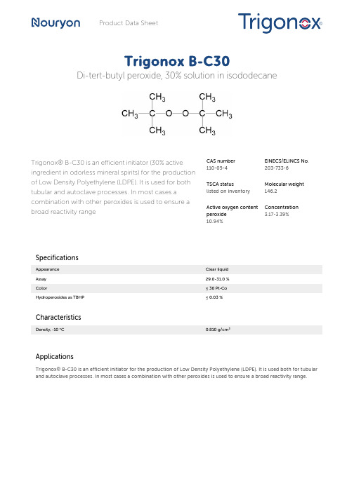
Product Data SheetTrigonox B-C30Di-tert-butyl peroxide, 30% solution in isododecaneTrigonox® B-C30 is an efficient initiator (30% active ingredient in odorless mineral spirits) for the production of Low Density Polyethylene (LDPE). It is used for both tubular and autoclave processes. In most cases a combination with other peroxides is used to ensure a broad reactivity range CAS number110-05-4EINECS/ELINCS No.203-733-6TSCA statuslisted on inventoryMolecular weight146.2Active oxygen contentperoxide10.94%Concentration3.17-3.39%SpecificationsAppearance Clear liquidAssay29.0-31.0 %Color≤ 30 Pt-CoHydroperoxides as TBHP≤ 0.03 %CharacteristicsDensity, -10 °C0.810 g/cm³ApplicationsTrigonox® B-C30 is an efficient initiator for the production of Low Density Polyethylene (LDPE). It is used both for tubular and autoclave processes. In most cases a combination with other peroxides is used to ensure a broad reactivity range.Half-life dataThe reactivity of an organic peroxide is usually given by its half-life (t1/2) at various temperatures. For Trigonox® B-C30 in chlorobenzene half-life at other temperatures can be calculated by using the equations and constants mentioned below:0.1 hr at 164°C1 hr at 141°C10 hr at 121°CFormula 1kd = A·e-Ea/RTFormula 2t½ = (ln2)/kdEa153.46 kJ/moleA 4.20E+15 s-1R8.3142 J/mole·KT(273.15+°C) KThermal stabilityOrganic peroxides are thermally unstable substances which may undergo self-accelerating decomposition. The lowest temperature at which self-accelerating decomposition may occur with a substance in the packaging as used for transport is the Self-Accelerating Decomposition Temperature (SADT). The SADT is determined on the basis of the Heat Accumulation Storage Test.Method The Heat Accumulation Storage Test is a recognized test method for thedetermination of the SADT of organic peroxides (see Recommendations on theTransport of Dangerous Goods, Manual of Tests and Criteria - United Nations, NewYork and Geneva).StorageDue to the relatively unstable nature of organic peroxides, a loss of quality will occur over a period of time. To minimize the loss of quality, Nouryon recommends a maximum storage temperature (Ts max. ) for each organic peroxide product.Ts max.40°CNote When stored according to these recommended storage conditions, Trigonox® B-C30 will remain within the Nouryon specifications for a period of at least 3 monthsafter delivery.Packaging and transportThe standard packaging is a 1000 l composite Intermediate Bulk Container (IBC). Delivery in a 20 m3 Nouryon tank container is also possible in a number of countries. Both packaging and transport meet the international regulations. For the availability of other packed quantities consult your Nouryon representative. Trigonox® B-C30 is classified as Organic peroxide type F; liquid, Division 5. 2; UN 3109.Safety and handlingKeep containers tightly closed. Store and handle Trigonox® B-C30 in a dry well-ventilated place away from sources of heat or ignition and direct sunlight. Never weigh out in the storage room. Avoid contact with reducing agents (e. g. amines), acids, alkalis and heavy metal compounds (e. g. accelerators, driers and metal soaps). Please refer to the Safety Data Sheet (SDS) for further information on the safe storage, use and handling of Trigonox® B-C30. This information should be thoroughly reviewed prior to acceptance of this product. The SDS is available at /sds-search.Major decomposition productsAcetone, Methane, tert-ButanolAll information concerning this product and/or suggestions for handling and use contained herein are offered in good faith and are believed to be reliable.Nouryon, however, makes no warranty as to accuracy and/or sufficiency of such information and/or suggestions, as to the product's merchantability or fitness for any particular purpose, or that any suggested use will not infringe any patent. Nouryon does not accept any liability whatsoever arising out of the use of or reliance on this information, or out of the use or the performance of the product. Nothing contained herein shall be construed as granting or extending any license under any patent. Customer must determine for himself, by preliminary tests or otherwise, the suitability of this product for his purposes.The information contained herein supersedes all previously issued information on the subject matter covered. The customer may forward, distribute, and/or photocopy this document only if unaltered and complete, including all of its headers and footers, and should refrain from any unauthorized use. Don’t copythis document to a website.Trigonox is a registered trademark of Nouryon Functional Chemicals B.V. or affiliates in one or more territories.Contact UsPolymer Specialties Americas************************Polymer Specialties Europe, Middle East, India and Africa*************************Polymer Specialties Asia Pacific************************2023-3-22© 2023Polymer production Trigonox B-C30。
低投资成本促使Degussa公司扩大在巴西的过氧化氢生产
低投资成本促使Degussa公司扩大在巴西的过氧化氢生产于剑昆(摘译)
【期刊名称】《化学推进剂与高分子材料》
【年(卷),期】2006(4)6
【摘要】一次具有吸引力的投资成本和在南美洲的机遇的偶然组合,激励了Dcgussa公司将其在巴西的过氧化氢(H2O2)产能提升至10万t/a。
该扩产计划将按照2步进行,第一步包括使用“高产率工作方案”,使其在BarradoRiacho的装置产量增加到7万t/a;在下一阶段中,Dcgussa公司将建造2套过氧化氢生产线,它将新增产能3万t/a。
【总页数】1页(P60-60)
【关键词】Degussa公司;过氧化氢;投资成本;生产线;巴西;南美洲;吸引力;高产率【作者】于剑昆(摘译)
【作者单位】
【正文语种】中文
【中图分类】TQ342.731
【相关文献】
1.日挥公司开发二甲醚制丙烯技术/Degussa推进过氧化氢/环氧丙烷一体化工艺的工业化进程/美开发可提高乙烯产量的装置控制系统/德Degussa推出应用于石化单体生产的服务工艺包 [J],
2.道康宁公司获准在华生产有机硅结构密封胶/Performance有机硅公司成为
Dow Corning的分销商/道康宁宣布增加硅烷产品产量/Degussa提高硅烷售价/Degussa在日本投资建沉淀法白炭黑厂/《气相法二氧化硅》国家标准审定会在广州召开 [J],
3.Degussa公司扩大特殊化学品生产 [J], 张泗文
4.Degussa公司和Headwaters公司计划以新路线生产过氧化氢 [J], 彭琳
5.Solvay公司扩大在美国的过氧化氢生产能力并且计划在智利进行新的投资 [J], 李建文
因版权原因,仅展示原文概要,查看原文内容请购买。
- 1、下载文档前请自行甄别文档内容的完整性,平台不提供额外的编辑、内容补充、找答案等附加服务。
- 2、"仅部分预览"的文档,不可在线预览部分如存在完整性等问题,可反馈申请退款(可完整预览的文档不适用该条件!)。
- 3、如文档侵犯您的权益,请联系客服反馈,我们会尽快为您处理(人工客服工作时间:9:00-18:30)。
¾三星级锅炉效率
在ECO3中,更新升级了多种内部部件,如: ¾新型卫生热水流量传感器; ¾新型主热交换器 ¾新型数字控制电路板 这些都极大地提高了ECO3系列锅炉的综合性能,按照CEE 92/42标准锅炉的效率达 到了***级,额定输出功率时的效率高达93%。
¾最高的IP保护等级
ECO3 系列壁挂炉的IP保护等级(防水、防尘保护等级)达到了行业内产品所能达到 的最高级IPX5D。
Documento riservato – A solo uso interno / Confidential document – Internal use only
¾ 完全由黄铜制成,确保部件的可靠性 及使用寿命
¾ 卫生热水不锈钢热交换器:超强的换 热器能力可以保证在恒定温度下,热水 的出水量达到13.7升/分钟,具有更好 的热舒适性
以往
新式
Documento riservato – A solo uso interno / Confidential document – Internal use only
板式热交换器 (combi models)
不锈钢制,特殊的流道设计,表面镜面处理,增强换热能 力,减少结垢风险
部件介绍
Documento riservato – A solo uso interno / Confidential document – Internal use only
Documento riservato – A solo uso interno / Confidential document – Internal use only
产品主要特点 ¾液晶屏显示 ¾三星级热效率,最高的IP保护等级 ¾ 双热交换器 ¾卫生热水舒适性高 ¾质量可靠,操作、维修方便。
Documento riservato – A solo uso interno / Confidential document – Internal use only
部件介绍
燃气阀
由两道安全阀及一道调节阀组成 安全阀 起开通/关闭燃气通路的作用 调节阀 调节燃气供应量的功能,根据主电脑板提供的直流电流来调节燃气流量
Documento riservato – A solo uso interno / Confidential document – Internal use only
• ECO3 280 Fi 强排型 – 28 kW 热水产量16,1 升/分钟 (ΔT 25°C)
Documento riservato – A solo uso interno / Confidential document – Internal use only
¾ 外形尺寸
• 与老款的ECO2000系列相同 • 760*450*345
Safety device indicators activation
当出现故障时,显示屏显示故障代码,根据故障代码可判断故障原因 (es.
E 10):
故障需重新启动
将选择开关旋转至“R”并至少停留2秒,然后再将选择开关旋转至某工作模式,壁挂炉即 可重新启动,如果重新启动三次后,故障仍不能排除,请直接联系当地技术服务中心。 注意:如果连续重新启动壁挂炉5次后,故障仍然存在,壁挂炉将锁定。 如果想解除锁定,只需将选择开关置于OFF位置并停留2秒中以上,然后打开壁挂炉。
谢谢!
Documento riservato – A solo uso interno / Confidential document – Internal use only
Documento riservato – A solo uso interno / Confidential document – Internal use only
室外温度传感器的连接
Documento riservato – A solo uso interno / Confidential document – Internal use only
Documento riservato – A solo uso interno / Confidential document – Internal use only
¾质量可靠,
操作、维修方便
¾水力组件采用黄铜材料 ¾电动三通阀 ¾不锈钢卫生热水换热器 ¾点火、火焰检测电极单 独设置 ¾旋钮+液晶显示屏,操作 简单,显示清晰。
¾ 电动三通阀:全面的防冻保护功能
¾ 新一代的低能耗热水循环泵(55W) :可节省超过25%的能耗
¾ 内置的自动旁通系统可在外部采暖系 统发生堵塞时有效的保护壁挂炉
New compact hydraulic group
Documento rise/ Confidential document – Internal use only
部件介绍
Documento riservato – A solo uso interno / Confidential document – Internal use only
电动三通换向阀
部件介绍
通过电动机来切换主热交换器出水的流向,从而切换壁挂炉的工作模式
相关信息
具备全面的防冻保护、防粘死功能
燃烧器及火焰检测装置
不锈钢制燃烧器,集合了点火电极及火焰检测电极。
点火电极
在点火过程中,通过脉冲高电压产生电火花,点燃燃气,点火 时间一般为8秒钟左右
火焰检测装置
燃气在燃烧过程中会发生电离,电路板通过在火焰检测电极上 施加一定的电压,从而会通过火焰与燃烧器形成一定的电流, 通过检测该电流的大小来判断火焰正常与否
风机
通过叶轮的旋转,使燃烧室内部形成负压,通过外界的大气 压将燃烧所需的新鲜空气送入燃烧室,并带走燃烧后的废气
相关功能
在采暖及卫生热水状态下,当燃烧室内燃烧停止后,风机继 续运转一定时间,以带走多余的热量,减少再次启动等待的 时间
部件介绍
Documento riservato – A solo uso interno / Confidential document – Internal use only
Documento riservato – A solo uso interno / Confidential document – Internal use only
部件介绍
自动旁通
当外部采暖系统水流量小于一定值时,旁通会自动打开,在机内形成 一定循环流量,确保壁挂炉的最小循环水量,从而保护壁挂炉
部件介绍
主热交换器
由铜管制成,外涂防腐蚀涂层 通过翅片吸收烟气中的热量,然后通过铜管传递给管内的水,铜管内 装有扰流片,增强换热效率 新型换热器,锅炉效率高达3星级
Documento riservato – A solo uso interno / Confidential document – Internal use only
Documento riservato – A solo uso interno / Confidential document – Internal use only
常见的故障信息
Documento riservato – A solo uso interno / Confidential document – Internal use only
• 燃烧器工作 • 燃气供应问题
• 卫生热水模式
• 需要重启符号
• CH供水温度 • CH-DHW 设定温度 • 故障代码 • 内部参数
• 缺水符号
Documento riservato – A solo uso interno / Confidential document – Internal use only
气候补偿功能的主要优势
¾ 采暖供水温度根据真实的室外温度自动调节; ¾ 在室外天气发生突然变化时,相比较与仅安装由室内温度控制装置的 采暖系统,带室外气候补偿装置的采暖系统对天气的变化反应更迅速; ¾ 采暖运行费用更低:进入采暖系统的供水温度被最大化的降低,减少 了管道的热损失
• 更舒适 • 更高效 • 更节能
冬/夏/复位
¾从锅炉前侧能接触到其 选择开关 内的所有部件,方便维修 。
液晶 显示屏
采暖温度 调节旋钮
卫生热水温度 调节旋钮
Documento riservato – A solo uso interno / Confidential document – Internal use only
• CH模式 • 故障警示
卫生热水流量传感器
利用霍尔原理,通过检测热水的流量来启动热水加热
部件介绍
Documento riservato – A solo uso interno / Confidential document – Internal use only
卫生热水流量传感器可以检测热水流量:
锅炉根据流量与设定的温度调节锅炉的输出功 率,当锅炉的热水需求发生变化时,锅炉可立 即作出反馈,保证热水供应的舒适性。
开-关 传感器 (水流开关)
Modulating sensor (流量计)
两种热水优先开关的特性比较,水流量从300 升/分钟升至600升/分钟. 流量计的优势是:
- 热水温度恢复的时间缩小了一半 - 更小的温度波动
Documento riservato – A solo uso interno / Confidential document – Internal use only
¾液晶屏显示
ECO3 系列配置液晶显示屏: BAXI在新一代ECO3产品中,结合应用了许多当今 世界上先进的控制、分析、显示技术。
在ECO3 的液晶显示屏上,可了解三个层次的锅炉 运行信息: 1、运行参数、状态信息 2、故障信息 3、锅炉内部参数(专为维修人员)
