tlp350
FSP350-60PLN中文资料
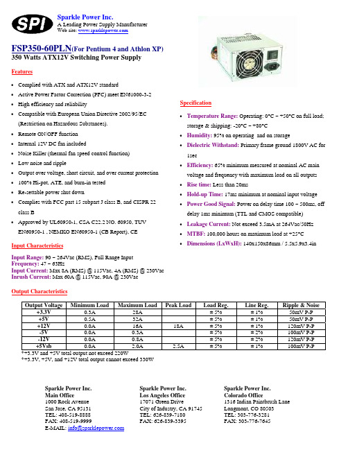
Input CharacteristicsInput Range: 90 ~ 264Vac (RMS), Full Range Input Frequency: 47 ~ 63HzInput Current: Max 8A (RMS) @ 115Vac, 4A (RMS) @ 230Vac Inrush Current: Max 60A @ 115Vac, 90A @ 230VacSparkle Power Inc.A Leading Power Supply ManufacturerWeb site: Specification• Temperature Range: Operating: 0°C ~ +50°C on full load; storage & shipping: -20°C ~ +80°C• Humidity: 95% on operating and on storage•Dielectric Withstand: Primary frame ground 1800V AC for 1sec•Efficiency: 65% minimum measured at nominal AC main voltage and frequency with maximum load on all outputs • Rise time: Less than 20ms• Hold-up Time: 17ms minimum at nominal input voltage • Power Good Signal: Power on delay time 100 ~ 500ms, off delay 1ms minimum (TTL and CMOS compatible) • Leakage Current: Not exceed 3.5mA at 264Vac/50Hz • MTBF: 100,000 hours on maximum load at +25°C •Dimensions (LxWxH): 140x150x86mm / 5.5x5.9x3.4inOutput CharacteristicsOutput Voltage Minimum Load Maximum LoadPeak Load Load Reg.Line Reg.Ripple & Noise +3.3V0.3A 28A± 5% ± 1% 50mV P-P +5V0.5A 32A± 5% ± 1% 50mV P-P +12V0.0A 16A 18A ± 5%± 1% 120mV P-P -5V0.0A 0.3A± 5% ± 2% 100mV P-P -12V0.0A 0.8A± 5% ± 2% 120mV P-P +5Vsb0.0A 2.0A 2.5A ± 5% ± 1% 100mV P-P*+3.3V and +5V total output not exceed 220W*+3.3V, +5V, and +12V total output cannot exceed 330WFSP350-60PLN (For Pentium 4 and Athlon XP) 350 Watts ATX12V Switching Power SupplySparkle Power Inc. Main Office1000 Rock Avenue San Jose, CA 95131 TEL: 408-519-8888 FAX: 408-519-9999E-MAIL: info@Sparkle Power Inc. Los Angeles Office 17071 Green DriveCity of Industry, CA 91745 TEL: 626-839-7180 FAX: 626-839-3395 Sparkle Power Inc. Colorado Office1316 Indian Paintbrush Lane Longmont, CO 80503 TEL: 303-776-3281 FAX: 303-776-7645Features• Complied with ATX and ATX12V standard• Active Power Factor Correction (PFC) meet EN61000-3-2 • High efficiency and reliability•Compatible with European Union Directive 2002/95/EC (Restriction on Hazardous Substances). • Remote ON/OFF function • Internal 12V DC fan included• Noise Killer (thermal fan speed control function) • Low noise and ripple• Output over voltage, short circuit, and over current protection • 100% Hi-pot, ATE, and burn-in tested • Re-settable power shut down•Complies with FCC part 15 subpart J class B, and CISPR 22 class B•Approved by UL60950-1, CSA C22.2 NO. 60950, TUV EN60950-1 , NEMKO EN60950-1 (CB Report), CE元器件交易网。
Cisco 350系列产品参数与价格表说明书
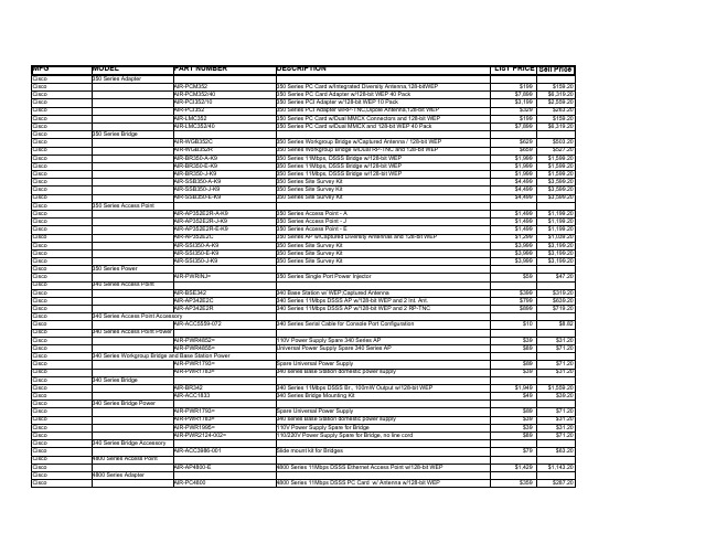
4800 Series Adapter
AIR-PC4800
DESCRIPTION
350 Series PC Card w/Integrated Diversity Antenna,128-bitWEP 350 Series PC Card Adapter w/128-bit WEP 40 Pack 350 Series PCI Adapter w/128-bit WEP 10 Pack 350 Series PCI Adapter w/RP-TNC,Dipole Antenna,128-bit WEP 350 Series PC Card w/Dual MMCX Connectors and 128-bit WEP 350 Series PC Card w/Dual MMCX and 128-bit WEP 40 Pack
350 Series Power
AIR-SSI350-J-K9 AIR-PWRINJ=
340 Series Access Point
AIR-BSE342
AIR-AP342E2C AIR-AP342E2R
340 Series Access Point Accessory AIR-ACC5559-072
350 Series Workgroup Bridge w/Captured Antenna / 128-bit WEP 350 Series Workgroup Bridge w/Dual RP-TNC and 128-bit WEP 350 Series 11Mbps, DSSS Bridge w/128-bit WEP 350 Series 11Mbps, DSSS Bridge w/128-bit WEP 350 Series 11Mbps, DSSS Bridge w/128-bit WEP 350 Series Site Survey Kit 350 Series Site Survey Kit 350 Series Site Survey Kit
ypt系列变频调速电机80400

YPT系列变频调速电机80400简介YPT系列变频调速电机80400,是一种新型的电机产品,能够根据不同的负荷要求进行变频调速,使得电机工作更加稳定。
该电机以永磁同步电机为主体,采用微机控制技术和高效能稀土永磁材料,实现了高效、节能、智能、环保的特性。
技术规格1.额定功率:75kW2.输出转速:0-2000r/min3.转矩:375N·m4.绝缘等级:F级5.防护等级:IP546.运行温度:-20℃~+40℃7.频率范围:0.02-400Hz产品特点1.高效节能YPT系列变频调速电机80400采用永磁同步电机技术,具有高效的电机效率、低音量和低能耗,与传统的交流异步电机相比可节能20%-30%以上。
2.智能化控制系统该电机内置微机控制器,可实时监测电机转速、转矩和运行状态,通过反馈控制实现恰当的输出电压和电流,从而大幅度减少能耗。
3.环保低噪音YPT系列变频调速电机采用高度稀土永磁材料,使电机噪音下降约3到5分贝。
同时,该电机实现无污染、无噪音排放,符合国家环保要求。
4.可靠性高电机的主要部件均采用高质量的材料,且通过了多种严格的测试与验证,确保电机的可靠性和稳定性。
应用领域YPT系列变频调速电机广泛应用于风力发电、水泵、压缩机等各种工业场所。
其中,风力发电和水泵是其主要应用领域之一。
由于其高效、智能、可靠的特性,得到了广大用户的青睐和追捧。
使用注意事项1.在使用前,请确认电机与电源线路连接正确,确保使用环境符合电机规定的工作条件。
2.使用时,请保持电机清洁,并根据规定定期加注润滑油。
3.如果遇到电机故障,请及时报修。
在维修和更换配件时,应按照说明书和技术要求进行操作。
4.停机前,请先断开电源,以确保人员安全。
自动化毕业设计论文题目大全

自动化毕业设计论文题目大全1.智能压力传感器系统设计2.智能定时器3.液位控制系统设计4.液晶控制模块的制作6.嵌入式激光打标机运动控制卡硬件系统设计7.基于单片机控制的数字气压计的设计与实现8.基于MSC1211的温度智能温度传感器9.机器视觉系统11.防盗报警器12.AT89S52单片机实验系统的开发与应用13.在单片机系统中实现SCR(可控硅)过零控制14.微电阻测量系统16.基于GSM短信模块的家庭防盗报警系统18.基于单片机的智能火灾报警系统19.WIN32环境下对PC机通用串行口通信的研究及实现20.FIR数字滤波器的MA TLAB设计与实现方法研究21.无刷直流电机数字控制系统的研究与设计22.直线电机方式的地铁模拟地铁系统制作23.稳压电源的设计与制作24.线性直流稳压电源的设计26.全自动汽车模型的设计制作27.单片机数字电压表的设计28.数字电压表的设计30.模拟量转换成为数字量的红外传输系统31.液位控制系统研究与设计33.基于单片机的居室安全报警系统设计38.模拟量处理为数字量红外语音传输接收系统的设计40.电话远程监控系统的研究与制作41.基于UCC3802的开关电源设计42.串级控制系统设计43.分立式生活环境表的研究与制作(多功能电子万年历)44.高效智能汽车调节器45.变速恒频风力发电控制系统的设计46.全自动汽车模型的制作47.信号源的设计与制作48.智能红外遥控暖风机设计49.基于单片控制的交流调速设计50.基于单片机的多点无线温度监控系统52.数字触发提升机控制系统53.农业大棚温湿度自动检测54.无人监守点滴自动监控系统的设计55.积分式数字电压表设计56.智能豆浆机的设计57.采用单片机技术的脉冲频率测量设计59.基于单片机实现汽车报警电路的设计60.多功能数字钟设计与制作61.超声波倒车雷达系统硬件设计62.基于A T89C51单片机的步进电机控制系统63.模拟电梯的制作64.基于单片机程控精密直流稳压电源的设计65.转速、电流双闭环直流调速系统设计66.噪音检测报警系统的设计与研究68.基于单片机的多功能函数信号发生器设计69.基于单片机的超声波液位测量系统的设计73.基于DS18B20的多点温度巡回检测系统的设计74.计数及数码显示电路的设计制作75.矿井提升机装置的设计77.数字PWM直流调速系统的设计78.开关电源的设计80.锅炉控制系统的研究与设计82.基于CPLD的出租车计价器设计——软件设计83.声纳式高度计系统设计和研究84.集约型无绳多元心脉传感器研究与设计86.六路抢答器设计88.机床润滑系统的设计89.塑壳式低压断路器设计90.直流接触器设计92.大棚温湿度自动控制系统93.基于单片机的短信收发系统设计――硬件设计94.三层电梯的单片机控制电路95.交通灯89C51控制电路设计96.基于D类放大器的可调开关电源的设计97.直流电动机的脉冲调速98.红外快速检测人体温度装置的设计与研制99.基于8051单片机的数字钟101.动力电池充电系统设计102.多电量采集系统的设计与实现103.PWM及单片机在按摩机中的应用104.IC卡预付费煤气表的设计105.基于单片机的电子音乐门铃的设计106.基于单片机的温湿度测量系统设计107.基于单片机的简易GPS定位信息显示系统设计108.基于单片机的简单数字采集系统设计109.大型抢答器设计110.新型出租车计价器控制电路的设计111.500kV麻黄线电磁环境影响计算分析112.单片机太阳能热水器测控仪的设计113.LED点阵显示屏-软件设计114.双容液位串级控制系统的设计与研究115.三电平Buck直流变换器主电路的研究116.基于PROTEUS软件的实验板仿真117.基于16位单片机的串口数据采集118.电机学课程CAI课件开发119.单片机教学实验板——软件设计120.PN结(二极管)温度传感器性能的实验研究121.微电脑时间控制器的软件设计122.基于单片机A T89S52的超声波测距仪的研制123.硼在TLP扩散连接中的作用机理研究124.多功能智能化温度测量仪设计125.电网系统对接地电阻的智能测量126.基于数字采样法的工频电参数测量系统的设计127.动平衡检测系统的设计128.非正弦条件下电参测量的研究129.频率测量新原理的研究130.基于LABVIEW的人体心率变异分析测量131.学校多功能厅音响系统的设计与实现132.利用数字电路实现电子密码锁133.矩形微带天线的设计134.简易逻辑仪的分析135.无线表决系统的设计136.110kV变电站及其配电系统的设计137.10KV变电所及低压配电系统设计138.35KV变电所及低压配电系统设计139.6KV配电系统及车间变电所设计140.交流接触器自动化生产流水线设计148.真空断路器的设计149.总线式智能PID控制仪150.自动售报机的设计151.小型户用风力发电机控制器设计152.断路器的设计153.基于MATLAB的水轮发电机调速系统仿真154.数控缠绕机树脂含量自控系统的设计155.软胶囊的单片机温度控制(硬件设计)156.空调温度控制单元的设计157.基于人工神经网络对谐波鉴幅158.基于单片机的鱼用投饵机自动控制系统的设计159.基于MATLAB的调压调速控制系统的仿真研究160.锅炉汽包水位控制系统161.基于单片机的无刷直流电机控制系统设计162.煤矿供电系统的保护设计——硬件电路的设计163.煤矿供电系统的保护设计——软件设计164.大容量电机的温度保护——软件设计165.大容量电机的温度保护——硬件电路的设计166.模块化机器人控制器设计167.电子式热分配表的设计开发168.中央冷却水温控制系统169.基于单片机的玻璃管加热控制系统设计170.基于AT89C51单片机的号音自动播放器设计171.基于单片机的普通铣床数控化设计172.基于AT89C51单片机的电源切换控制器的设计173.基于51单片机的液晶显示器设计174.手机电池性能检测175.自动门控制系统设计176.汽车侧滑测量系统的设计177.超声波测距仪的设计及其在倒车技术上的应用179.基于单片机控制的红外防盗报警器的设计180.智能多路数据采集系统设计181.继电器保护毕业设计182.电力系统电压频率紧急控制装置研究183.用单片机控制的多功能门铃184.全氢煤气罩式炉的温度控制系统的研究与改造185.基于ATmega16单片机的高炉透气性监测仪表的设计186.基于MSP430的智能网络热量表187.火电厂石灰石湿法烟气脱硫的控制188.家用豆浆机全自动控制装置189.新型起倒靶控制系统的设计与实现190.软开关技术在变频器中的应用195.用单片机实现电话远程控制家用电器196.无线话筒制作197.温度检测与控制系统198.数字钟的设计199.汽车尾灯电路设计203.基于RS485总线的远程双向数据通信系统的设计204.宾馆客房环境检测系统205.智能充电器的设计与制作206.基于单片机的电阻炉温度控制系统设计207.单片机控制的PWM直流电机调速系统的设计208.遗传PID控制算法的研究216.步进电机实现的多轴运动控制系统217.IC卡读写系统的单片机实现218.基于单片机的户式中央空调器温度测控系统设计219.基于单片机的乳粉包装称重控制系统设计220.18B20多路温度采集接口模块221.基于单片机防盗报警系统的设计222.基于MAX134与单片机的数字万用表设计223.数字式锁相环频率合成器的设计224.集中式干式变压器生产工艺控制器225.小型数字频率计的设计226.可编程稳压电源227.数字式超声波水位控制器的设计228.基于单片机的室温控制系统设计229.基于单片机的车载数字仪表的设计230.单片机的水温控制系统231.数字式人体脉搏仪的设计235.智能恒压充电器设计236.基于单片机的定量物料自动配比系统237.现代发动机自诊断系统探讨238.基于单片机的液位检测239.基于单片机的水位控制系统设计244.他励直流电动机串电阻分级启动虚拟实验245.并励直流电动机串电阻三级虚拟实验252.基于87C196MC交流调速实验系统软件的设计与开发253.87C196MC单片机最小系统单路模板的设计与开发254.MOSFET管型设计开关型稳压电源255.电子密码锁控制电路设计256.基于单片机的数字式温度计设计257.智能仪表用开关电源的设计258.遥控窗帘电路的设计259.双闭环直流晶闸管调速系统设计260.三路输出180W开关电源的设计261.多点温度数据采集系统的设计262.列车测速报警系统263.PIC单片机在空调中的应用264.基于单片机的温度采集系统设计265.基于单片机89C52的啤酒发酵温控系统266.基于MCS-51单片机温控系统设计的电阻炉267.基于单片机的步进电机控制系统272.基于MCS-96单片机的双向加力式电子天平273.语音控制小汽车控制系统设计274.智能型客车超载检测系统的设计275.热轧带钢卷取温度反馈控制器的设计276.直流机组电动机设计277.龙门刨床驱动系统的设计278.基于单片机的大棚温、湿度的检测系统279.微波自动门280.基于DS18B20温度传感器的数字温度计设计281.节能型电冰箱研究286.基于单片机的实时时钟287.基于MCS-51通用开发平台设计288.基于MP3格式的单片机音乐播放系统289.基于单片机的IC卡智能水表控制系统设计290.基于MATLAB的FIR数字滤波器设计297.单片机电器遥控器的设计298.自动剪板机单片机控制系统设计304.单片机与PC串行通信设计310.温度测控仪设计311.数字频率计312.数字集成功率放大器整体电路设计316.路灯控制器317.扩音机的设计318.交直流自动量程数字电压表319.交通灯控制系统设计324.电机遥控系统设计328.家用对讲机的设计329.流速及转速电路的设计330.基于单片机的家电远程控制系统设计334.逆变电源设计335.基于单片机的电火箱调温器336.表面贴片技术SMT的广泛应用及前景337.中型电弧炉单片机控制系统设计338.中频淬火电气控制系统设计339.新型洗浴器设计350.软开关直流逆变电源研究与设计351.单片机电量测量与分析系统352.温湿度智能测控系统353.现场总线控制系统设计354.加热炉自动控制系统362.智能定时闹钟设计363.数字音乐盒设计364.数字温度计设计365.数字定时闹钟设计366.数字电压表设计367.计算器模拟系统设计368.定时闹钟设计369.电子万年历设计370.电子闹钟设计371.单片机病房呼叫系统设计378.汽车防盗系统379.简易远程心电监护系统386.试论供电系统中的导体和电器的选择387.大棚仓库温湿度自动控制系统388.自行车车速报警系统389.智能饮水机控制系统390.基于单片机的数字电压表设计391.多用定时器的电路设计与制作392.智能编码电控锁设计393.串联稳压电源的设计401.感应式门铃的设计与制作408.公交车站自动报站器的设计409.单片机波形记录器的设计410.音频信号分析仪411.基于单片机的机械通风控制器设计412.论电气设计中低压交流接触器的使用419.浅析数字信号的载波传输420.浅析通信原理中的增量控制421.太阳能热水器水温水位测控仪分析422.电气设备的漏电保护及接地423.论“人工智能”中的知识获取技术424.论PLC应用及使用中应注意的问题425.论传感器使用中的抗干扰技术426.论电测技术中的抗干扰问题427.论高频电路的频谱线性搬移428.论高频反馈控制电路436.论无损探伤的特点437.论在线检测438.论专家系统439.论自动测试系统设计的几个问题440.浅析时分复用的基本原理441.试论配电系统设计方案的比较442.试论特殊条件下交流接触器的选用443.音频功率放大器的设计444.具有红外保护的温度自动控制系统的设计445.直流数字电压表的设计452.基于立体声调频收音机的研究456.基于高速公路监控系统的研究457.多种变化彩灯458.单片机音乐演奏控制器设计459.单片机的打印机的驱动设计460.单目视觉车道偏离报警系统461.基于单片机的压电智能悬臂梁振动控制系统设计462.遥控小汽车的设计研究463.单片机的数字电压表设计464.多路输出直流稳压源469.火灾自动报警系统470.基于单片机的电子时钟控制系统475.国产化PLC的研制476.串行显示的步进电机单片机控制系统477.编码发射与接收报警系统设计:看护机481.红外线遥控器系统设计484.基于嵌入式系统的原油含水分析仪的硬件与人机界面设计485.低频功率放大器设计486.银行自动报警系统487.超媒体技术488.数字电子钟的设计与制作489.温度报警器的电路设计与制作490.数字电子钟的电路设计491.鸡舍电子智能补光器的设计492.高精度超声波传感器信号调理电路的设计493.电子密码锁的电路设计与制作494.单片机控制电梯系统的设计495.常用电器维修方法综述496.控制式智能计热表的设计497.电子指南针设计498.汽车防撞主控系统设计499.电力拖动控制系统设计500.解析民用建筑的应急照明501.对漏电保护器安全性能的剖析502.基于单片机的多功能智能小车设计503.电气火灾自动保护型断路器的设计504.电力电子技术在绿色照明电路中的应用505.单片机的智能电源管理系统514.汽车倒车雷达515.基于DSP的电机控制523.基于AT89C51的路灯控制系统设计524.点阵式汉字电子显示屏的设计与制作525.全数字控制SPWM单相变频器526.小功率UPS系统设计527.正弦信号发生器电路设计528.基于Matlab的多频率FMICW的信号分离及时延信息提取B接口设备驱动程序的框架设计530.单片机大型建筑火灾监控系统531.单片机电加热炉温度控制系统532.单片机控制单闭环直流电动机的调速控制系统533.通用串行总线数据采集卡的设计534.全氢罩式退火炉温度控制系统535.网络视频监控系统的设计536.一氧化碳报警器537.基于DSP的短波通信系统设计IIR设计538.电压稳定毕业设计539.基于ARM的嵌入式web服务器的设计与实现540.数字式心电信号发生器硬件设计及波形输出实现541.电话卡代拨器的设计542.基于单片机的遥控器的设计543.数字电容测量仪的设计544.基于MCU温控智能风扇控制系统的设计545.红外遥控电子密码锁的设计546.水位报警显时控制系统的设计547.生产流水线产品产量统计显示系统548.数字温度计的设计549.基于单片机设计的自动售货机系统设计550.基于USB总线的设计与开发551.通过USB实现PC间数据传输552.超声波特征提取系统553.单片机实验教学平台分析554.110kv电网继电保护设计555.16×16点阵LED电子显示屏的设计560.基于单片机A T89C51的语音温度计的设计561.基于单片机的带智能自动化的红外遥控小车564.单片机呼叫系统的设计565.音频多重混响设计566.探讨未来通信技术的发展趋势567.智能小车自动寻址设计--小车悬挂运动控制系统568.湿度传感器单片机检测电路制作569.单片机定时闹钟设计570.基于单片机的多点温度检测系统571.智能火灾报警监测系统572.智能立体仓库系统的设计573.单片机交通灯控制系统的设计574.交流电机型式试验及计算机软件的研究575.大功率电器智能识别与用电安全控制器的设计579.基于虚拟仪器的电网主要电气参数测试设计580.单片机演奏音乐歌曲装置的设计581.单片机电铃系统设计582.智能电子密码锁设计583.八路智能抢答器设计584.基于单片机控制音乐门铃585.基于单片机控制文字的显示586.基于单片机控制发生的数字音乐盒587.基于单片机控制动态扫描文字显示系统的设计588.基于LMS自适应滤波器的MATLAB实现589.D功率放大器毕业论文593.智能电话报警器597.基于单片机的智能电子负载系统设计598.电压比较器的模拟与仿真599.脉冲变压器设计600.MATLAB仿真技术及应用601.基于单片机的水温控制系统603.发电机-变压器组中微型机保护系统604.基于单片机的鸡雏恒温孵化器的设计605.基于单片机步进电机控制系统设计606.多路数据采集系统的设计608.基于单片机的数字钟设计609.自动存包柜的设计610.空调器微电脑控制系统611.全自动洗衣机控制器612.小功率不间断电源(UPS)中变换器的原理与设计613.电力线载波调制解调器毕业设计论文614.图书馆照明控制系统设计616.电视伴音红外转发器的设计617.多传感器障碍物检测系统的软件设计618.基于单片机的电器遥控器设计619.基于单片机的数码录音与播放系统620.单片机控制的霓虹灯控制器621.电阻炉温度控制系统622.智能温度巡检仪的研制623.保险箱遥控密码锁624.基于蓝牙技术的心电动态监护系统的研究627.卷扬机自动控制限位控制系统628.磁敏传感器水位控制系统629.继电器控制两段传输带机电系统630.广告灯自动控制系统632.霍尔传感器水位控制系统633.全自动车载饮水机634.浮球液位传感器水位控制系统635.干簧继电器水位控制系统636.电接点压力表水位控制系统637.低成本智能住宅监控系统的设计638.大型发电厂的继电保护配置639.直流操作电源监控系统的研究640.悬挂运动控制系统641.气体泄漏超声检测系统的设计642.电压无功补偿综合控制装置646.数字显示式电子体温计647.基于单片机的病床呼叫控制系统648.红外测温仪649.基于单片微型计算机的测距仪650.基于单片微型计算机的多路室内火灾报警器651.基于单片微型计算机的语音播出的作息时间控制器652.交通信号灯控制电路的设计653.信号发生器654.智能数字频率计659.函数信号发生器设计论文660.单片机控制步进电机毕业设计论文661.基于单片机的数字电压表662.恒温箱单片机控制663.单片机控制的全自动洗衣机毕业设计论文664.单片机脉搏测量仪665.双闭环直流调速系统设计668.红外报警器设计与实现669.正弦信号发生器670.水电站电气一次及发电机保护671.单片机汽车倒车测距仪672.基于单片机的自行车测速系统设计673.基于MCS51单片机温度控制毕业设计论文674.开关稳压电源设计675.单片机控制步进电机676.步进电动机竹竿舞健身娱乐器材677.超声波测距仪毕业设计论文678.语音电子门锁设计与实现679.工厂总降压变电所设计-毕业论文680.单片机无线抢答器设计681.基于单片机控制直流电机调速系统毕业设计论文682.单片机串行通信发射部分毕业设计论文683.基于VHDL语言PLD设计的出租车计费系统毕业设计论文684.基于单片机的数字显示温度系统毕业设计论文685.单片机控制的数控电流源毕业设计论文686.声控报警器毕业设计论文687.基于单片机的锁相频率合成器毕业设计论文688.基于Multism/protel的数字抢答器689.单片机智能火灾报警器毕业设计论文690.无线多路遥控发射接收系统设计毕业论文691.数字频率计毕业设计论文692.单片机对玩具小车的智能控制毕业设计论文693.基于单片机控制的电机交流调速毕业设计论文694.楼宇自动化--毕业设计论文695.车辆牌照图像识别算法的实现--毕业设计696.超声波测距仪--毕业设计697.工厂变电所一次侧电气设计698.电子测频仪--毕业设计699.点阵电子显示屏--毕业设计700.电子电路的电子仿真实验研究701.单片机数字钟设计702.自动起闭光控窗帘毕业设计论文708.宽带视频放大电路的设计709.简易数字存储示波器设计毕业论文710.球赛计时计分器711.IIR数字滤波器的设计毕业论文712.PC机与单片机串行通信毕业论文713.基于CPLD的低频信号发生器设计毕业论714.基于51单片机的多路温度采集控制系统715.仓库温湿度的监测系统716.基于单片机的电子密码锁717.单片机控制交通灯系统设计718.智能抢答器设计719.基于DSP的IIR数字低通滤波器的设计与实现720.基于LabVIEW的PC机与单片机串口通信721.DSP设计的IIR数字高通滤波器的设计722.单片机数字钟设计723.数字自动打铃系统724.激光切割轨道系统的上位机设计725.由A T89C51控制的太阳能热水器726.单片机歩进电机转速控制器的设计727.频率特性测试仪的设计728.用集成温度传感器组成测温控制系统729.微尺度观测仪的物理原理及应用730.低频数字式相位差测量仪的设计731.智能开关稳压电源的设计735.小型风光互补路灯控制器设计736.基于MCS-51单片机的高精度数字测相装置的设计737.基于单片机的火灾自动报警系统738.数字显示多路电压设计739.智能防盗报警系统设计740.数字调频立体收音机741.基于单片机的水温控制系统742.电子广告牌的设计743.电力变压器保护744.变电站综合自动化系统研究745.智能象棋比赛定时器的设计746.基于单片机的电动车跷跷板747.艺术彩灯设计748.基于单片机的密码锁设计749.双输出可调稳压电源的设计750.用IC卡实现门禁管理系统751.智能消毒柜控制系统752.自动太阳光追踪器753.基于89C51的点阵屏显示设计754.利用AT89C5单片机实现节日彩灯控制755.自动温度控制系统756.室内温度控制报警器757.8751H单片机控制步进电机758.高精密多路计时器759.小型触摸式防盗报警器760.频率特性测试仪设计761.出租车计价器762.数控直流稳压电源设计763.数字电度表--具有远程抄表功能764.基于多单片机的数据测控硬件系统的设计765.基于MATLAB的他励直流电机虚拟教学实验系统的设计与开发766.基于87C196MC交流调速系统主电路硬件的设计与开发767.基于80C196MC交流调速系统控制电路的硬件设计与开发768.多环教学实验系统模拟电子电路控制模板的设计与开发773.调幅收音机的原理与调试774.电力线载波系统775.基于单片机的温室电炉的控制系统776.基于MCS-51单片机的变色灯控制系统设计与实现777.基于单片机的频率计的设计778.烤箱温度控制系统779.电容测量仪780.基于AT89S51单片机的波形发生器设计781.简易低频信号发生器782.基于单片机的红外遥控开关783.发动机电喷内核模型的研究及实践784.基于AT89S52的函数信号发生器785.智能住宅的功能设计与实现原理研究786.基于PIC16F876A单片机的超声波测距仪787.基于单片机的呼叫系统的设计788.电容测量电路的设计789.电压频率变换器790.基于单片机的IC卡门禁系统设计791.压阻式传感器在压力方面的技术应用792.全集成电路高保真扩音机793.单片机控制的三相全控桥触发系统设计794.IC卡智能燃气表的研制795.传感器信号模拟电路设计研究796.基于C8051F040单片机的智能电导率分析仪797.基于MODBUS协议的远程端口控制系统798.两路电力线加载信号检测识别系统799.单片机的语音存储与重放的研究800.基于单片机的电器遥控器的设计。
Helvar调光驱动器说明书

Functional Description• DALI Type 8 compatible. One DALI address for controlling colour temperature by two output channels• DALI colour type: Colour temperature T c• Adjustable constant current output: 100 mA to 1200 mA• Current setting programmable via NFC, DALI or with external (LED-Iset) resistors • Suitable for flicker-free camera recording applications• Patented Switch-Control 2 functionality for easy-to-use intensity and colour temperature control with single push button • Full load recognition with automatic recovery, open and short circuit protection• Multipurpose terminal LED-Iset/NTC for current setting or overtemperature protection • Constant Light Output (CLO), adjustable up to 100 000 h (default disabled)• Energy consumption monitor (real time), running hour monitor (accumulative), energy management (accumulative)• Memory bank for OEM customer dataMains CharacteristicsNominal rated voltage range 220 V – 240 V, 0 / 50 – 60 Hz AC voltage range 198 VAC – 264 VAC Withstands max. 320 VAC (max. 1 hour) DC voltage range 176 VDC – 280 VDC DC starting voltage > 190 VDC Mains current at full load 0.23 - 0.26 A Frequency 0 / 50 Hz – 60 Hz Stand-by power consumption < 0.5 W THD at full power < 10 %Leakage current to earth < 0.7 mA Tested surge protection 1 kV L-N, 2 kV L-GND (IEC 61000-4-5)Tested fast transient protection 2 kV (IEC 61000-4-4)Insulation between circuits & driver caseMains circuit - SELV circuitDouble/reinforced insulation DALI circuit - SELV circuit Double/reinforced insulation Mains circuit - DALI circuit Basic insulation Output - Driver case Basic insulationMains and DALI circuit - Driver case Double/reinforced insulation Mains input - Ground inputDouble/reinforced insulationLoad Output (SELV <60 V)Output current (I out ) 100 mA – 1200 mAAccuracy ± 5 %1)Ripple < 1 %2) at ≤ 120 Hz1) At 350 - 1200 mA range. 2) Low frequency, LED load: Cree XP-G LED s.PstLM < 0.23)SVM < 0.01 3)3) At full power, measured with Cree XP-G LED modules.50 W Dimmable two channel intelligent Colour LED driver• 2-channel tunable white for human centric lighting• Wide dynamic range of colour temperatures on all dimming levels *• 0.1 % - 100 % dimming range per single channel (total range 2 % - 100 %)*• SELV output protection for safety and flexibility in luminaires• Amplitude dimming for the highest quality light output, complying with IEEE 1789 recommendation• NFC technology for wireless programming• Suitable for DC use• Ideal solution for Class I and Class II • Helvar Driver Configurator support*) See pages 2-3 for details50 W 220 – 240 V 0/ 50 –60 HzProduct code: 5775OUT(MAX) .Amplitude dimming technologyLL50iC-DA-100-1200 LED driver implements amplitude dimming technology across whole dimming range. Amplitude dimming offers the best available technology for dimming the light output in an accurate and flicker-free way to ensure high quality lighting in even the most demanding situations such as camera recording applications. Amplitude dimming technology complies with IEEE 1789-2015 recommendations of current modulation to mitigate health risks to viewers.100 %L E D c u r r e n tBrightnessD y n a m i c r a n g eDynamic range in colour temperature controlLL50iC-DA-100-1200 LED driver is ready to be used out of the box.Highest precision and color consistency in controlling combinations of different luminaire types is achieved by setting colour temperatures and lumen outputs before use with Helvar driver configurator. The configured colour temperatures of the channels should match the ones of the LED modules used. The factory default settings of cool and warm channels are 6500 K and 2700 K accordingly.After setting up the colour temperatures, the lumen output values of full dimming level (100 %) should be configured for both channels. By default, output currents are set to be equal in both channels.Total available dimming rangeset output currentD y n a m i c r a n g eSwitch-Control with tunable whiteRetractive SwitchHelvar iC drivers provide the simplest form of control in tunable white with Helvar patented single switch Switch-Control functionality. With single push button the user is able to control both the light intensity and colour temperature to the desired level. The system synchronises the light levels and CCTs every time the colour temperature is adjusted to ensure pleasant user experience and uncompromised lighting comfort. More information about the functionality can be found in Switch-Control user guide at .Wireless configurationLL50iC-DA-100-1200 LED driver is equipped with NFC wireless technology for effortless configuration of the driver via Helvar Driver Configurator Support. Helvar Driver Configurator enables easy-to-use automatic configuration of the driver parameters via NFC, without mains or DALI connection to the driver. The most popular MD-SIG qualified NFC readers (FEIG CPR30-USB & ISC.MR102-USB ) are supported giving flexibility for the operator. For further information about the usage with Helvar Driver Configura-tor, please see the user guide at Quantity of drivers per miniature circuit breaker 16 A Type CTotal continous current of the drivers and installation environment must always be considered and taken into calculations when installing drivers behind miniature circuit breaker. Example calculation of total drivers amount limited by continous current: n(I cont ) = (16 A (I nom,Ta ) / “nominal mains current with full load”) x 0.76). This calculation is an example according to recommended precautions due to multiple adjacent circuit breakers (> 9 MCBs) and installa-tion environment (T a 30 degrees); variables may vary according to the use case. Both inrush current and continous current calculations are based on ABB S200 series circuit breakers. More specific information in ABB series S200 circuit breaker documentation.NOTE! Type C MCB’s are strongly recommended to use with LED lighting. Please see more details in “MCB information” document in each driver product page in “downloads & links” section.CONTINOUS CURRENT I ½ IConnections and Mechanical DataWire size 0.5 mm 2 – 1.5 mm 2Wire type Solid core and fine-stranded Wire insulation According to EN 60598Maximum driver to LED wire length 1.5 m Weight 263 g IP rating IP20Helvar LED-Iset resistors and currents (Nominal I out(±5 % tol.*))The current can be adjusted also with normal resistors by selecting suitable resistor value (formula R [Ω] = (5 [V] / I_out [A]) * 1000). Reference resistor values can be found below order code in the table above.The LED-Iset resistor/current setting values are adjusted according to the LEDset specification. The resistor value for each required output current can thus be calculated from the formula R [Ω] = (5 [V] / I_out [A]) * 1000. Below are the available LED-Iset resistors from Helvar, pre-adjusted for the most common output currents.LL50iC-DA-100-1200 LED driver is suited for built-in usage in luminaires. In order to have safe and reliable LED driver operation, the LED luminaires will need to comply with the relevant standards and regulations (e.g. IEC/EN 60598-1). The LED luminaire shall be designed to adequately protect the LED driver from dust, moisture and pollution. The luminaire manufacturer is responsible for the correct choice and installation of the LED drivers according to the application and product datasheets. Operating conditions of the LED drivers may never exceed the specifications as per the product datasheet.Installation & operationMaximum ambient and t c temperature :• For built-in components inside luminaires, the t a ambienttemperature range is a guideline given for the optimum operating environment. However, integrator must always ensure proper thermal management (i.e. mounting base of the driver, air flow etc.) so that the t c point temperature does not exceed the t c maximum limit in any circumstance.• Reliable operation and lifetime is only guaranteed if the maximum t c point temperature is not exceeded under the conditions of use.Current setting resistorLL50iC-DA-100-1200 LED driver features a constant current output adjustable via current setting resistor.• An external resistor can be inserted in to the current settingterminal, allowing the user to adjust the LED driver output current.• When no external resistor is connected, then the LED drivers willoperate at their default lowest current level.• A standard through-hole resistor can be used for the current setting. To achieve the most accurate output current it is recommended to select a quality low tolerance resistor. Minimum diameter for resistor leg is 0.51mm.• Always connect the current setting resistor only into theterminals marked with LED-Iset on the LED driver label.• For the resistor/current values, refer to the table on page 4.LED driver earthing• LL50iC-DA-100-1200 is LED driver suitable for Class I and IIluminaires. When used inside Class I and Class II luminaires, the earth cable is recommended to be connected to improve the EMC performance of the driver, but it is not mandatory. It is the responsibility of the integrator to ensure that the assembled luminaire EMC performance complies with the latest standards. Miniature Circuit Breakers (MCB)• Type-C MCB’s with trip characteristics in according to EN 60898are recommended.• Please see more details in “MCB information” document in eachdriver product page in “downloads & links” section.Helvar Driver Configurator -supportLL50iC-D A-100-1200 LED driver is supported by Helvar D river configurator software. The LL50iC-D A-100-1200 driver supports output current setting with software, the output current of the driver can be programmed using Helvar D river Configurator, as well as OEM customer data and parameters for functions such as CLO and Tunable White behavior. Programming the driver with Helvar Driver Configurator can be done either wirelessly via NFCor then via DALI bus. Also the operation of the multifunction LED-Iset terminal usage can be changed from current setting resistor(default) to NTC overtemperature protection mp failure functionalityNo loadWhen open load is detected, driver will go to standby power consumption and remains in automatic recovery mode. In automatic recovery mode, the driver waits till load is returned and once that happens, it returns to normal operation.Short circuitWhen short circuit is detected, driver goes to automatic recoverymode and follows the same logic as described in the no load condition.OverloadWhen overload is detected, driver goes to standby mode and returnsthrough mains reset.UnderloadWhen undervoltage is detected, driver goes to standby mode and returns through mains reset.NTC triggerWhen NTC is enabled via Helvar Driver Configurator, driver follows NTC feature behaviour. D efault NTC trigger point is 8,2 kΩ, after which the driver starts to decrease the output level.Switch-Control 2Use of Switch-Control functionality• Maximum numbers of LED drivers to be connected to one switchis 60. Wire length is not restricted by the driver technology.• Ensure that all components connected to Switch-Controlcircuitry are mains rated.• More information in Switch-Control User Guide at www.helvar.com.Conformity & standardsGeneral and safety requirements EN 61347-1 Particular safety requirements for DCor AC supplied electronic control gearfor LED modulesEN 61347-2-13Additional safety requirements for AC or DC supplied electronic controlgear for emergency lighting EN 61347-2-13, Annex JThermal protection class EN 61347, C5e Mains current harmonics EN 61000-3-2 Limits for voltage fluctuations andflickerEN 61000-3-3 Radio frequency interference EN 55015 Immunity standard EN 61547 Performance requirements EN 62384 Digital addressing lighting interface:General requirements for DALI system Requirements for DALI control gear Requirements for control gear of LED modulesParticular requirements for control gear - Colour control (Dali Device Type 8)EN 62386-101 EN 62386-102 EN 62386-207EN 62386-209Recommended Practices forModulating Current in High-BrightnessLEDs for Mitigating Health Risks toViewersIEEE 1789-2015Compliant with relevant EU directivesRoHS/REACH compliantCE/UKCA and ENEC markedLabel symbolsSafety isolating control gear with short circuit protection(SELV control gear).Double insulated control gear suitable for built-in use.Thermally controlled control gear, incorporating means of protection against overheating to prevent the case temperature under any conditions of use from exceeding 120°C.D riverequipped with NFC wireless technology for effortless configuration.Helvar Intelligent Colour drivers providing DALI colour control (tunable white) functionality.。
TLP3506驱动工作原理电路
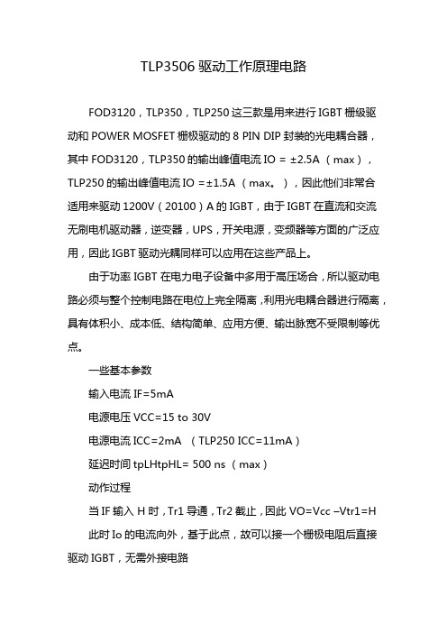
TLP3506驱动工作原理电路FOD3120,TLP350,TLP250这三款是用来进行IGBT栅级驱动和POWER MOSFET栅极驱动的8 PIN DIP封装的光电耦合器,其中FOD3120,TLP350的输出峰值电流IO = ±2.5A (max),TLP250的输出峰值电流IO =±1.5A (max。
),因此他们非常合适用来驱动1200V(20100)A的IGBT,由于IGBT在直流和交流无刷电机驱动器,逆变器,UPS,开关电源,变频器等方面的广泛应用,因此IGBT驱动光耦同样可以应用在这些产品上。
由于功率 IGBT 在电力电子设备中多用于高压场合,所以驱动电路必须与整个控制电路在电位上完全隔离,利用光电耦合器进行隔离,具有体积小、成本低、结构简单、应用方便、输出脉宽不受限制等优点。
一些基本参数输入电流 IF=5mA电源电压VCC=15 to 30V电源电流ICC=2mA (TLP250 ICC=11mA)延迟时间tpLHtpHL= 500 ns (max)动作过程当IF输入 H 时,Tr1导通,Tr2截止,因此 VO=Vcc –Vtr1=H 此时Io的电流向外,基于此点,故可以接一个栅极电阻后直接驱动IGBT,无需外接电路当IF输入 L 时,Tr1截止,Tr2导通,此时 VO=Vgnd+Vtr2=L 此时如果IGBT栅极上有残存的电荷,可通过Tr2到GND进行放电,关闭IGBT逻辑关系如下注意事项1. 为了保证电压的稳定,防止电压突变损坏IGBT,需要在8脚与5脚间需要接一个0.1uF的电容。
2. IGBT大多是工作于感性负载状态,当其处于关断状态,反并二极管正在反向恢复过程时,就会有很大的dvdt加于CE两端,由于米勒电容的存在,I=C*dudt,将会产生瞬间电流流向驱动电路,与栅极电阻作用,将产生电压,此电压若超过IGBT栅极开启电压,则会造成IGBT误触发导通,因此提供负偏压Vge能有效防止误触发,建议VE接负压。
I.C.T IR350插线SMT PCBA路由器说明书
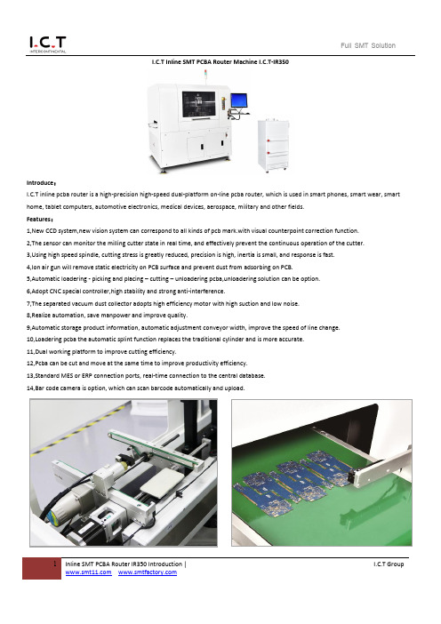
1Inline SMT PCBA Router IR350 Introduction |I.C.T GroupI.C.T Inline SMT PCBA Router Machine I.C.T-IR350Introduce :I.C.T inline pcba router is a high-precision high-speed dual-platform on-line pcba router, which is used in smart phones, smart wear, smart home, tablet computers, automotive electronics, medical devices, aerospace, military and other fields. Features :1,New CCD system,new vision system can correspond to all kinds of pcb mark.with visual counterpoint correction function. 2,The sensor can monitor the milling cutter state in real time, and effectively prevent the continuous operation of the cutter. 3,Using high speed spindle, cutting stress is greatly reduced, precision is high, inertia is small, and response is fast. 4,Ion air gun will remove static electricity on PCB surface and prevent dust from adsorbing on PCB.5,Automatic loadering - picking and placing – cutting – unloadering pcba,unloadering solution can be option. 6,Adopt CNC special controller,high stability and strong anti-interference.7,The separated vacuum dust collector adopts high efficiency motor with high suction and low noise. 8,Realize automation, save manpower and improve quality.9,Automatic storage product information, automatic adjustment conveyor width, improve the speed of line change. 10,Loadering pcba the automatic splint function replaces the traditional cylinder and is more accurate. 11,Dual working platform to improve cutting efficiency.12,Pcba can be cut and move at the same time to improve productivity efficiency. 13,Standard MES or ERP connection ports, real-time connection to the central database. 14,Bar code camera is option, which can scan barcode automatically and upload.2Inline SMT PCBA Router IR350 Introduction |I.C.T GroupConfiguration :Feeding SystemThe new feeding system replaces the traditional cylinder structure to ensure more accurate feeding and automatic width adjustment of the conveyor. Unloading to conveyor belt, with detection function, easy to use at the back of the station, unloading conveyor modeis optional.Pick&Place SystemUsing precise double servo to pick and place Pcba instead of traditional cylinder (or double cylinder to take and place)Double servo screw structure pick and place Pcba will improve the accuracy.The Z1 axis is responsible for picking Pcba in and out of the board, while the Z2 axis is responsible for picking Pcba out and putting it in the next station after the cutting is completed. The traditional which has the disadvantages of slow speed. Dual mechanicalpick-and-place structure greatly improves operation efficiency and productivity.CCD camera alignment system, Milling cutter Auto-change system,Whole board scanning function,MES system,Precision Dust-proof Module, The UPH is calculated automatically.Intelligent Milling Tool Database,Automatic recording of products cut byeach milling cutter to achieve traceability3Inline SMT PCBA Router IR350 Introduction | I.C.T Group PartsBrand Place of origin X-axis servomoter Panasonic Japan Y-axis servomoter Panasonic Japan Z-axis servomoter Panasonic Japan Main-axis/ spindle NSK Japan CCD MINTRON Taiwan I/O Board I.C.T China Guide rail PMI/HIWIN Taiwan Ball screw PMI Taiwan Coupling NBK Japan Sensor Takex Japan Tank Chain IGUS Germany Flexible cable IGUS Germany Bearing NSK Japan Switch, Button TD,LJTaiwanSpecification :PCB Router I.C.T-IR350 Pcb Size 300*350mm Platform Number Double PCB thickness 0.3~6.0mmPCB support mode Multifunctional fixture, special fixtureX 、Y Cutting Speed 0~100mm/s Repeat Precision ± 0.01mm X 、Y 、Z Driving Method AC Servo motor X 、Y 、Z Control mode CNC controllerIon air gun≤±15v (ESD 12M09158A58)Operation and Data Storage PC System Cut Precision± 0.08mm Rotational Speed of the Main Shaft Max 80000rpm Voltage220V,50/60HZ Air Pressure Supply 4.5kg/cm2 Power Supply1.5kw Weight(with vacuum cleaner) 1100kg Dimension1930*1350*1700mm Dust Collection Method Vacuum cleaning Air volume of vacuum cleaner 28~35m³/min Vacuum cleaner Dimension 750*600*620mm Voltage of the Dust Collector380V,50/60HZ,3kw* I.C.T keeps working on quality and performance,specifications and appearance may be updated without particular notice.Thanks for choosing I.C.T.I.C.T looks forward to win-win cooperation.4Inline SMT PCBA Router IR350 Introduction | I.C.T Group。
标准电路V3.4

标准电路V3.3版更改记录1. 增加耳机插座的AV输入电路(AV_Three in one),并增加了简化版AV输入电路2. 增加耳机插座的YPbPr输入电路(YPbPr_Three in one),并增加了简化版YPbPr输入电路3. 增加SD_CARD电路4. 增加DDR3 电路(K4B2G1646C)5. 增加 SERIAL FLASH 电路6. 增加eMMC电路7. 增加RESET电路8.优化功放电路:功放TAS5707、STA380、STA381中3.3V数字电源输入的220Ω磁珠去掉,模拟电源输入的220Ω磁珠改为120Ω;功放TAS5707的MCLK和BCLK之间预留33Ω跳线电阻;功放STA381增加耳机保护电路9.LOCAL_DIMMING中CS脚的滤波电容删除10.IR主板电路的5V电源脚预留0Ω串接电阻位,并将原来的滤波电容NC11.MAINPOWER电路中DIM直流控制脚的串接电阻和滤波电容NC12.MHL电路中限流IC的EN脚加10K下拉电阻13.优化DC-DC电路:MP2905 增加了输入欠压锁存电路;AOZ1284 输出5V时,RD91改为33K;TPS54519 输出电容增加一颗22UF电容CD7814.增加DTMB电路系统技术组2013-7-19第 2 页标准电路V3.2.1版更改记录1.增加了FFC模块接口电路2.增加了WiFi模块接口电路3.电路的排版顺序进行了调整4.增加了带隔离器的TUNNER182575.对位号以及版面进行了优化改善系统技术组2013-4-28 第 4 页标准电路V3.2版 更改记录1、AVOUT电路:增加基极分压电阻及滤波电容,提高视频输出信噪比。
2、IR单色指示灯电路:删除1‐亮、0‐灭电路,保留0‐亮、1‐灭电路,增加主板端IR插头5pin、7pin兼容插座,提高组件一致性。
3、USB接口电路:为开发多家供应商,更改限流保护IC为RT9711AGBG。
TLP350

Note 1: Pulse width PW ≤ 1 µs, 300 pps Note 2: Exponential waveform pulse width PW ≤ µs, f ≤ Note 3: Ta ≤ 100 °C A (≤ µs), IOPL ≤ + A (≤ µs),Ta = °C kHz
Note 8: Input signal rise time (fall time) < 0.5 µs.
2
2003-10-27
TLP350
Electrical Characteristics (Ta = −40 to 100°C, unless otherwise specified)
CP350功率表说明书
壹.前言CP-300系列是智慧型多功能功率表,采用微处理控制,辅以软体校正方式达到CLOSE CASE校验境界,有校正容易,维修方便的优点,拥有7种量测功能、4组显示视窗,一组RS-232界面,7种量测功能分是V、A、Hz、W、PF、VA、VAR。
而V、A、Hz各以一组视窗显示,余W、PF、VA、VAR则共用一视窗。
V、A各有3档,瓦特则多至9档。
具有手动及自动换档功能,频率表采用全自动换档,V,A,Hz频宽高达100KHz,非常适合于高频率电源测试。
RS-232界面为标准配备,可搭配在ATE上使用。
CP-300系列智慧型功率表有下列机种:1-1附件︰选购配备︰1-2参.规格特性Basic specificationLine measure :Single phase, two conductor (1Ø2ω)Values measured :Voltage, current, Active power, Power factor,reactive power, apparent power, frequency.Measurement ranges :Voltage, current and active power see separatetable of ranges and resolutionFrequency:10Hz~100KHzOperating principle :Voltage and current:True RMSPower:Analog multiplier circuit.Range selection :Auto or manual (remote via RS-232)Sampling rate :3.3 times/secInput impedance :Voltage:approx 1MΩCurrent:approx 10mΩ(CP-310, CP-320A)approx 5mΩ(CP-350) Maximum allowable input :Voltage:650VrmsCurrent:20A RMS 50A peak(CP-310, CP-320A)50A RMS 125A peak (CP-350) Maximum common mode:Voltage and current input terminals:600Vrms voltageCrest factor :3Input method :Voltage:resistance dividerCurrent:shuntInput terminals :Large binding posts.Effective input range :5% to 100% of the set range.Temperature Coefficient :Less than ±0.05% f.s/℃Averaging function :Displays computed average (fix 3 measured).Computing FunctionComputing Range :VA, VAR:Voltage and current rangePF :Zero to unity leading or lagging.Computing Accuracy :VA, VAR:±0.05% of rated valuePF :±0.0013-1Frequency measurement functionOperating principle:Reciprocal counting method.Measurement range:5% to 100% set range (10Hz~100KHz)Auto Range:450Hz/10KHz/100KHzAccuracy:±1 DGT of the rangeMeasurement cycle:3.3 times/secDisplay Range:10.00Hz~99999Hz (5 digits)InterfaceRS-232:Baud Rate :1200,2400,9600 bpsTransmission system:Start-stop synchronization. 8 bit ,1 stop bit ,none parity Accuracy (at 23℃±5℃, power factor 1, warm-up time at least 30 minutes) Power Range and Resolution3-2※规格若有变更恕不另行通知3-3(12)电流显示器:测量电流显示,最大显示值为20.00A。
TPL7407L高压低侧驱动器说明书
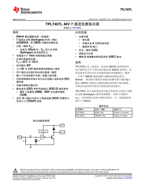
TPL7407L ZHCSC16A–JANUARY2014–REVISED JANUARY2014TPL7407L40V7通道低侧驱动器查询样片:TPL7407L特性应用范围•600mA额定漏极电流(每通道)•电感负载•7通道达灵顿(Darlington)阵列(例如–继电器ULN2003A)的CMOS引脚到引脚改进–单极步进&有刷直流电机•功耗(极低V OL)–螺线管&阀门–电流为100mA时,V OL低于达灵顿•发光二极管(LED)(Darlington)阵列的四分之一•逻辑电平位移•每通道小于10nA的极低输出泄露•栅极&绝缘栅双极型晶体管(IGBT)驱动•扩展环境温度范围:T A=-40°C至125°C说明•高压输出40V TPL7407L是一款高压、高电流NMOS晶体管阵列。
•与1.8V至5.0V微控制器和逻辑接口兼容这个器件包含7个特有高压输出的NMOS晶体管,这•用于感应反冲保护的内部自振荡二极管些晶体管具有针对开关电感负载的共阴极钳位二极管。
•输入下拉电阻器可实现三态输入驱动器一个单个NMOS通道的最大漏极电流额定值为•用来消除嘈杂环境中寄生运行的输入电阻电容(RC)600mA。
增加的全新稳压和驱动电路在整个通用输入缓冲器输出(GPIO)范围内(1.8V-5.0V)提供最大驱动强度。
•电感负载驱动器应用可将这些晶体管并联以实现更高的电流能力。
•静电放电(ESD)保护性能超过JESD22规范要求TPL7407L的主要优势是其经提升的效率以及低于双极–2kV人体模型(HBM),500V充电器件模型达灵顿(Darlington)器件的泄露值。
借助于较低的(CDM)V OL,功率耗散比传统中继驱动器少一半,每通道的电•采用16引脚小外形尺寸集成电路(SOIC)和薄型小流少于250mA。
外形尺寸(TSSOP)封装器件信息订货编号封装(引脚)封装尺寸TPL7407L SOIC(16)9.9mm x3.91mmTPL7407L TSSOP(16) 5.0mm x4.4mm 简化电路原理图Please be aware that an important notice concerning availability,standard warranty,and use in critical applications ofTexas Instruments semiconductor products and disclaimers thereto appears at the end of this data sheet.TPL7407L TSSOP/SOICTPL7407LZHCSC16A –JANUARY 2014–REVISED JANUARY 2014These devices have limited built-in ESD protection.The leads should be shorted together or the device placed in conductive foam during storage or handling to prevent electrostatic damage to the MOS gates.TERMINAL CONFIGURATION AND FUNCTIONSTerminal FunctionsTERMINALDESCRIPTIONNAME NUMBER IN(X)1,2,3,4,5,6,7GPIO inputs that will drive the outputs "low"(or sinnk current)when driven "high"16,15,14,13,12,11,OUT(X)Driver output that sinks currents after input is driven "high"10COM 9Supply PIn that should be tied to 8.5V or higher for proper operation GND8Ground pinSpecificationsAbsolute Maximum Ratings (1)at 25°C free-air temperature (unless otherwise noted)MINMAX UNIT V OUT Pins OUT1-OUT7to GND voltage -0.342V V OK Ouput Clamp diode reverse voltage (2)-0.342V V COM COM pin voltage (2)-0.342V V IN Pins IN1-IN7to GND voltage (2)-0.330V I DS Continuous drain current per channel (3)(4)600mA I OK Output clamp current500mA I GND Total continuous GND-terminal current –2A T A Operating free-air temperature range –40125°C T J Operating virtual junction temperature -40150°C T stg Storage temperature range–65150°C(1)Stresses beyond those listed under "absolute maximum ratings"may cause permanent damage to the device.These are stress ratings only,and functional operation of the device at these or any other conditions beyond those indicated under "recommended operating conditions"is not implied.Exposure to absolute-maximum-rated conditions for extended periods may affect device reliability.(2)All voltage values are with respect to the GND/substrate terminal,unless otherwise noted.(3)Maximum power dissipation is a function of T J (max),θJA ,and T A .The maximum allowable power dissipation at any allowable ambient temperature is P D =(T J (max)–T A )/θJA .Operating at the absolute maximum T J of 150°C can affect reliability.(4)The package thermal impedance is calculated in accordance with JESD 51-7.TPL7407L ZHCSC16A–JANUARY2014–REVISED JANUARY2014Thermal InformationTPL7407LTHERMAL METRIC(1)SOIC(D)TSSOP(PW)UNIT16PINS16PINSθJA Junction-to-ambient thermal resistance91.9115.2°C/WθJCtop Junction-to-case(top)thermal resistance50.149.5°C/WθJB Junction-to-board thermal resistance49.460.8°C/WψJT Junction-to-top characterization parameter18.68.5°C/WψJB Junction-to-board characterization parameter49.160.2°C/WθJCbot Junction-to-case(bottom)thermal resistance N/A N/A°C/W (1)For more information about traditional and new thermal metrics,see the IC Package Thermal Metrics application report,SPRA953.Recommended Operating ConditionsOver operating temperature rangeMIN NOM MAX UNITV OUT OUT1-OUT7pin voltage for recommended operation040VV COM COM pin voltage range for full output drive8.540VV IL IN1-IN7input low voltage("Off"high impedance output)0.9VV IH IN1-IN7input high voltage("Full Drive"low impedance output) 1.5VT J Operating virtual junction temperature-40125°CI DS Continuous drain current0500mAElectrical CharacteristicsT J=–40°C to125°C;Typical Values at T A=T J=25°CPARAMETER TEST CONDITIONS MIN TYP MAX UNITV IN≥1.5V I D=100mA200320 OUT1-OUT7low-level outputV OL(V DS)mV voltage I=200mA420650DI OUT(OFF)(I DS_OFF)OUT1-OUT7OFF-state leakage V OUT=24V,V IN≤1.0V10500nAcurrentV F Clamp forward voltage I F=200mA 1.4VI IN(off)IN1-IN7Off-state input current V INX=0V V OUT=40V500nAI IN(ON)IN1-IN7ON state input current V INX=1.5V-5.0V10μAI COM Static current flowing through COM V COM=8.5V-40V1525μApinSwitching CharacteristicsTypical Values at T A=T J=25°CPARAMETER TEST CONDITIONS MIN TYP MAX UNITPropagation delay time,low-to high-level350t PLH V INX≥1.65V,Vpullup=24V,Rpull-up=48Ωns outputPropagation delay time,high-to low-level350t PHL V INX≥1.65V,Vpullup=24V,Rpull-up=48Ωns outputC i Input capacitance V I=0,f=100KHz5pFTPL7407LZHCSC16A–JANUARY2014–REVISED Typical CharacteristicsOL DS(TSSOP)Cycle at25°C Cycle at70°CTPL7407L ZHCSC16A–JANUARY2014–REVISED JANUARY2014Typical Characteristics(continued)Cycle at25°C Cycle at70°C()J(MAX)A (MAX)JAT T PD -=q ND OLi Lii 1P V I ==´åTPL7407LZHCSC16A –JANUARY 2014–REVISED JANUARY 2014APPLICATION AND IMPLEMENTATIONTTL and other Logic InputsTPL7407L input interface is specified for standard 1.8V and 5V CMOS logic interface and can tolerate up to 30V.At any input voltage the output drivers will be driven at it's maximum when Vcom is greater than or equal to 8.5V.Input RC SnubberTPL7407L features an input RC snubber that helps prevent spurious switching in noisy environment.Connect an external 1k Ωto 5k Ωresistor in series with the input to further enhance TPL7407L’s noise tolerance.High-impedance Input DriversTPL7407L features a 1M Ωinput pull-down resistor.The presence of this resistor allows the input drivers to be tri-stated.When a high-impedance driver is connected to a channel input the TPL7407L detects the channel input as a low level input and remains in the OFF position.The input RC snubber helps improve noise tolerance when input drivers are in the high-impedance state.On-chip Power DissipationUse the below equation to calculate TPL7407L on-chip power dissipation P D :Where:N is the number of channels active together.V OLi is the OUT i pin voltage for the load current I Li .(1)Thermal ReliabilityIt is recommended to limit TPL7407L IC’s die junction temperature to less than 125°C.The IC junction temperature is directly proportional to the on-chip power e the following equation to calculate the maximum allowable on-chip power dissipation for a target IC junction temperature:Where:T J(MAX)is the target maximum junction temperature.T A is the operating ambient temperature.θJA is the package junction to ambient thermal resistance.(2)Improving Package Thermal PerformanceθJA value depends on the PC board layout.An external heat sink and/or a cooling mechanism,like a cold air fan,can help reduce θJA and thus improve device thermal capabilities.Refer to TI’s design support web page at /thermal for a general guidance on improving device thermal performance.TPL7407L ZHCSC16A–JANUARY2014–REVISED JANUARY2014 Application ExamplesUnipolar Stepper Motor DriverFigure9shows an implementation of TPL7407L for driving a uniploar stepper motor.The unconnected input channels can be used for other functions.When an input pin is left open the internal1MΩpull down resistor pulls the respective input pin to GND potential.For higher noise immunity use an external short across an unconnected input and GND pins.The COM pin must be tied to the supply of whichever inductive load is being driven for the driver to be protected by the free-wheeling diode.Figure9.TPL7407L as a Stepper Motor DriverTPL7407LZHCSC16A–JANUARY2014–REVISED Multi-Purpose Sink DriverWhen configured as per Figure10TPL7407L can be used as a multi-purpose driver.The output channels can be tied together to sink more current.TPL7407L can easily drive motors,relays&LEDs with little power dissipation. COM must be tied to highest load voltage,which may or may not be same as inductive load supply.VSUPFigure10.TPL7407L Multi-Purpose Sink Driver ApplicationTPL7407L ZHCSC16A–JANUARY2014–REVISED JANUARY2014 24V Relay DriverTo drive lower resistance relays,like<48Ω,connect two or more adjacent channels in parallel as shown in Figure11.Connecting several channels in parallel lowers the channel output resistance and increases the drive current.TPL7407L can be used for driving12V,24V&36V relays with similar a implementation.Figure11.TPL7407L Driving24V RelaysTPL7407LZHCSC16A–JANUARY2014–REVISED REVISION HISTORYChanges from Original(January2014)to Revision A Page •初次发布完整版本。
东芝TLP350F光耦合器数据表说明书

TOSHIBA Photocoupler GaA ℓAs IRED + Photo ICTLP350FIndustrial InverterInverter for Air ConditionerIGBT/Power MOSFET Gate Drive IH(Induction Heating)The TOSHIBA TLP350F consists of a GaA ℓAs light-emitting diode and an integrated photodetector.This unit is an 8-lead DIP package.The TLP350F is suitable for gate driving IGBTs or power MOSFETs.Absolute maximum ratings and electrical characteristics are the same as TLP350technical datasheet.• Peak output current: I O = ±2.5A (max)• Guaranteed performance over temperature: −40 to 100°C • Supply current:I CC = 2 mA (max) • Power supply voltage: V CC = 15 to 30 V • Threshold input current : I FLH = 5 mA (max) • Switching time (t pLH /t pHL ) : 500 ns (max) • Common mode transient immunity: 15 kV/μs • Isolation voltage: 3750 Vrms• UL Recognized : UL1577,File No.E67349 • Option(D4)VDE Approved : DIN EN 60747-5-2Maximum Operating Insulation Voltage : 1140V PK Highest Permissible Over Voltage : 6000V PK (Note): When an EN60747-5-2 approved type is needed, Please designate “Option(D4)”• Construction mechanical ratingTruth Table Input LED Tr1 Tr2 Output H ON ON OFF H LOFF OFF ONLUnit: mmTOSHIBA 11-10C402 Weight: 0.54 g (typ.)81: NC 2: Anode 3: Cathode 4: NC 5: GND6: V O (output)7: NC 8: V CC7 6 51234A 0.1 μF bypass capacitor must be connected between pins 8 and 5. (See Note 6)2+3−V CCV OGND(Tr1)(Tr2) I CC I O I FV F8657.62mm pitch TLP350 type 10.16mm pitch TLP350F type Creepage distance ClearanceInsulation thickness6.4 mm (min) 6.4 mm (min) 0.4 mm (min) 8.0 mm (min) 8.0 mm (min) 0.4 mm (min)Pin Configuration (top view)SchematicRESTRICTIONS ON PRODUCT USE20070701-EN •The information contained herein is subject to change without notice.•TOSHIBA is continually working to improve the quality and reliability of its products. Nevertheless, semiconductor devices in general can malfunction or fail due to their inherent electrical sensitivity and vulnerability to physical stress. It is the responsibility of the buyer, when utilizing TOSHIBA products, to comply with the standards of safety in making a safe design for the entire system, and to avoid situations in which a malfunction or failure of such TOSHIBA products could cause loss of human life, bodily injury or damage to property.In developing your designs, please ensure that TOSHIBA products are used within specified operating ranges as set forth in the most recent TOSHIBA products specifications. Also, please keep in mind the precautions and conditions set forth in the “Handling Guide for Semiconductor Devices,” or “TOSHIBA Semiconductor Reliability Handbook” etc.• The TOSHIBA products listed in this document are intended for usage in general electronics applications (computer, personal equipment, office equipment, measuring equipment, industrial robotics, domestic appliances, etc.).These TOSHIBA products are neither intended nor warranted for usage in equipment that requires extraordinarily high quality and/or reliability or a malfunction or failure of which may cause loss of human life or bodily injury (“Unintended Usage”). Unintended Usage include atomic energy control instruments, airplane or spaceship instruments, transportation instruments, traffic signal instruments, combustion control instruments, medical instruments, all types of safety devices, etc.. Unintended Usage of TOSHIBA products listed in his document shall be made at the customer’s own risk.•The products described in this document shall not be used or embedded to any downstream products of which manufacture, use and/or sale are prohibited under any applicable laws and regulations.• The information contained herein is presented only as a guide for the applications of our products. No responsibility is assumed by TOSHIBA for any infringements of patents or other rights of the third parties which may result from its use. No license is granted by implication or otherwise under any patents or other rights of TOSHIBA or the third parties.•GaAs(Gallium Arsenide) is used in this product. The dust or vapor is harmful to the human body. Do not break, cut, crush or dissolve chemically.• Please contact your sales representative for product-by-product details in this document regarding RoHS compatibility. Please use these products in this document in compliance with all applicable laws and regulations that regulate the inclusion or use of controlled substances. Toshiba assumes no liability for damage or losses occurring as a result of noncompliance with applicable laws and regulations.。
TLP350

A 0.1 F bypass capacitor must be connected between pins 8 and 5. (See Note 6)
1
2005-08-05
TLP350
Maximum Ratings (Ta 25°C)
Characteristic
Symbol
Rating
Unit
Operating temperature range
Lead soldering temperature (10 s) Isolation voltage (AC, 1 minute, R.H. ≤ 60%)
(Note 4) (Note 5)
IF IF/ Ta IFP VR
Tj IOPH IOPL VCC VCC / Ta
UL Recognized
: UL1577,File No.E67349
Option(D4)
VDE Approved : DIN EN60747-5-2
Maximum Operating Insulation Voltage : 890VPK
Highest Permissible Over Voltage
Forward current
Forward current de-rating (Ta ≥ 85°C)
LE D
Peak transient forward current
(Note 1)
Reverse voltage
Junction temperature
“H” peak output current “L” peak output current
3
2005-08-05
TLP350
SHARP光耦替换其它品牌型号对照表

TLP114/TLP112/TLP109 PC400J00000F
ACPL-P480-500E
Pin To Pin
PC410L0NIP0F稳定性优于TLP115A
Pin To Pin
PC457L0NIP0F稳定性优于TLP109
Pin5、4脚位和Avago 定义相反
PC400J00000F已广泛应用
1.PC925LENIP0F响应速率比TLP350要高
变频器、UPS电源
2.PC925LENIP0F绝缘电压是5KV,TLP350是3.75KV。
、电动汽车等等
1.PC925LENIP0F响应速率比TLP250要高 2.PC925LENIP0F绝缘电压是5KV,TLP350是3.75KV。
变频器、UPS电源 、电动汽车等等
变频器、各类电 源,驱动器等
变频器、各类电 源,驱动器等
变频器、各类电 源,驱动器等 变频器、各类电 源,驱动器等
变频器、各类电 源,驱动器等
伺服、驱动器等
伺服、驱动器等
SHARP一致性好
Pin To Pin
稳定性优于Toshiba
PC900V0NSZXF H11L1/H11L3-TOSHIBA
Pin To Pin
相当
PC851XJ0000F TLP628
Hale Waihona Puke Pin To Pin稳定性优于Toshiba的TLP628
应用行业
变频器、各类电 源,驱动器等
变频器、各类电 源,驱动器等 变频器、各类电 源,驱动器等
HCPL-181-00_E
TLP185_B - Toshiba
需要改板 Pin To Pin Pin To Pin
TLP555中文资料
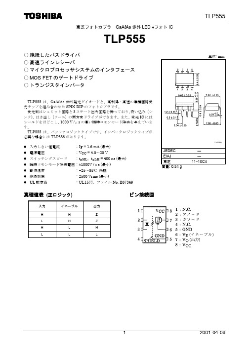
TLP555
注: 8 ピンと 5 ピンの間に、バイパス用のコンデンサ 0.1μF をつける必要があります。
最大定格 (Ta = 25℃)
項目
発 直流順電流
光 過 渡 パ ル ス 順 電 流 (注 1) 側
直流逆電圧
出
力
電
流
ピ ー ク 出 力 電 流 (注 2)
受
出
力
電
圧
光
電
源
電
圧
側 3 ステートイネーブル電圧
2
2001-04-06
推奨動作条件
項目
記号
最小 標準 最大 単位
入力ハイレベル電流、ON 入力ローレベル電圧、OFF
電
源
電
圧
ハイレベルイネーブル電圧
ローレベルイネーブル電圧 フ ァ ン ア ウ ト (TTL 負荷)
動
作
温
度
IF (ON) VF (OFF)
VCC VEH VEL
N Topr
2*
―
0
―
出 力 許 容 損 失 (注 3)
全 許 容 損 失 (注 4)
動
作
温
度
保
存
温
度
は ん だ 付 け 温 度 (10 秒 ) **
絶
縁
耐
圧
(AC1 分間、R.H.≦60%、Ta = 25℃)
(注 5)
記号
IF IFPT VR IO IOP VO VCC VE PO PT Topr Tstg Tsol
BVS
1.0
1.7
V
― mV /℃
10 μA
―
pF
100 μA
tlp350的经典使用案例
tlp350的经典使用案例TLP350是一款高速光耦隔离器,广泛应用于工业控制、通信设备、仪器仪表等领域。
其经典使用案例如下:1. 工业自动化控制系统:TLP350可用于工业自动化控制系统中的隔离接口,实现信号的隔离和传输。
例如,将PLC输出信号通过TLP350隔离后,再传输给驱动器或执行器,实现对电机或执行器的控制。
2. 电力系统监控:TLP350可以用于电力系统的监控和保护,实现信号的隔离和传输。
例如,将电力系统中的电流、电压等信号通过TLP350隔离后,传输给监控设备,实时监测电力系统的状态。
3. 医疗设备:TLP350可应用于医疗设备中,实现信号的隔离和传输。
例如,在医疗设备中,将传感器采集到的信号通过TLP350隔离后,传输给控制系统,实现对医疗设备的控制和监测。
4. 通信设备:TLP350可以用于通信设备中的信号隔离和传输。
例如,在光纤通信系统中,将光信号转换为电信号后,通过TLP350隔离后再传输,保证信号的稳定和可靠传输。
5. 智能家居系统:TLP350可以应用于智能家居系统中,实现信号的隔离和传输。
例如,在智能家居系统中,将传感器采集到的温度、湿度等信号通过TLP350隔离后,传输给控制中心,实现对家居设备的智能控制。
6. 电力电子设备:TLP350可用于电力电子设备中的信号隔离和传输。
例如,在变频器中,将控制信号通过TLP350隔离后,传输给功率模块,实现对电机的精确控制。
7. 安防监控系统:TLP350可以应用于安防监控系统中,实现信号的隔离和传输。
例如,在监控摄像头中,将视频信号通过TLP350隔离后,传输给监控系统,实现对监控画面的实时监测。
8. 仪器仪表:TLP350可用于仪器仪表中的信号隔离和传输。
例如,在测量仪器中,将测量信号通过TLP350隔离后,传输给数据采集系统,实现对测量数据的准确采集。
9. 汽车电子系统:TLP350可以应用于汽车电子系统中,实现信号的隔离和传输。
PL350使用说明书
机将自动开机并收到指定的电台节
定
时 目,这时屏幕上的 “ ” 符号开
始闪烁,30 分钟后,收音机会自动
自
关机。
动
提示:收音机自动开机后,只
开
机 有[电源/睡眠开关](1)和[照明/贪
睡]键(4)起作用,其他按键均处于
功
锁定状态。
能
如果您还想做其他操作,只要
按一下[电源/睡眠开关](1)即可解
除按键锁定。
步骤 1:利用定时开机功 能自动开机。
步骤 2:按一下[照明/贪
睡]键(4)可暂时关闭收音机,
使 即启动了贪睡功能。
用
贪
10 分钟后收音机再次响
睡 起,如没有人为进行干预,收
功 音机会在 30 分钟后自动关
能 闭。
提示:第 2 步操作可重复 3 次,当第 4 次按[照明/贪睡] 键(4)时,会关闭收音机,屏 幕上的“ ”符号也停止闪 烁。
步 骤 2
连接稳压电源
按一下[充电开关](16)即开始 充电。
提示:充电过程中遇到问题详见 步 “常见问题与解答”。 骤 3
六、时间设置
步骤 1: 在关机状态下,按住[时 间设置]键(17),直到屏幕上 的时间开始闪烁时松手。
步骤 2:
调 按一下[向上/小时]键
整 (6),然后旋转[多功能旋
当 钮](25)调整小时。
步骤 1:在关机状态下, 输入系统设置码 28,屏幕上出
现闪烁的“
”符
选 号。
择
步骤 2:按[向上/小时]
充 键 ,将数字调整到
电“
”。
电
步骤 3:再按一下[系统设
池 置]键(15)确认,3 秒钟后,屏
- 1、下载文档前请自行甄别文档内容的完整性,平台不提供额外的编辑、内容补充、找答案等附加服务。
- 2、"仅部分预览"的文档,不可在线预览部分如存在完整性等问题,可反馈申请退款(可完整预览的文档不适用该条件!)。
- 3、如文档侵犯您的权益,请联系客服反馈,我们会尽快为您处理(人工客服工作时间:9:00-18:30)。
TOSHIBA Photocoupler GaA ℓAs IRED + Photo ICTLP350Inverter for Air ConditionerIGBT/Power MOS FET Gate Drive Industrial InverterThe TOSHIBA TLP350 consists of a GaA ℓAs light emitting diode and a integrated photodetector.This unit is 8-lead DIP package.TLP350 is suitable for gate driving circuit of IGBT or power MOS FET..• Peak output current: I O = ±2.0 A (max)• Guaranteed performance over temperature: −40 to 100°C • Supply current:I CC = 2 mA (max) • Power supply voltage: V CC = 15 to 30 V • Threshold input current : I FLH = 5 mA (max) • Switching time (t pLH /t pHL ) : 500 ns (max) • Common mode transient immunity: 15 kV/µs • Isolation voltage: 3750 VrmsTruth TableInput LED Tr1 Tr2 Output H ON ON OFF H LOFF OFF ONLPin Configuration (top view)SchematicUnit: mmJEDEC ―JEITA―TOSHIBA 11-10C4 Weight: 0.54 g (typ.)PreliminaryA 0.1 µF bypass capacitor must be connected between pin 8 and 5. (See Note 6)2+3−CCOV FMaximum Ratings (Ta = 25°C)Characteristics Symbol Rating UnitForward currentI F 20 mA Forward current derating (Ta ≥ 85°C) ∆I F /∆Ta−0.54 mA/°CPeak transient forward current (Note 1)I FP 1 A Reverse voltage V R 5 V L E DJunction temperature T j 125 °C “H” peak output current (Note 2)I OPH−2.0 A“L” peak output current(Note 2)I OPL 2.0 A Output voltage (Note 3)V O 35 V Supply voltage (Note 3)V CC 35 V D e t e c t o rJunction temperatureT j 125 °COperating frequency (Note 4) f kHz Storage temperature range T stg −55 to 125 °C Operating temperature range T opr−40 to 100°CLead soldering temperature (10 s)(Note 5)T sol 260 °C Isolation voltage (AC, 1 minute, R.H. ≤ 60%)(Note 6)BV S 3750 VrmsNote 1: Pulse width P W ≤ 1 µs, 300 ppsNote 2: Exponential waveform pulse width P W ≤ µs, f ≤ kHz Note 3: Ta ≤ 100 °CNote 4: Exponential waveform I OPH ≤ A (≤ µs), I OPL ≤ + A (≤ µs),Ta = °C Note 5: It is 2 mm or more from a lead root.Note 6: Device considerd a two terminal device: pins 1, 2, 3 and 4 shorted together, and pins 5, 6, 7 and 8 shortedtogether. Note 7: A ceramic capacitor(0.1 µF) should be connected from pin 8 to pin 5 to stabilize the operation of the highgain linear amplifier. Failure to provide the bypassing may impair the switching property. The total lead length between capacitor and coupler should not exceed 1 cm.Recommended Operating ConditionsCharacteristics Symbol Min Typ.MaxUnitInput current, ON (Note 8)I F (ON) 7.5 10 mA Input voltage, OFF V F (OFF) 00.8 VSupply voltage V CC 15 30 V Peak output current I OPH /I OPL±1.0A Operating temperatureT opr−40100°CNote 8: Input signal rise time (fall time) < 0.5 µs.Characteristics SymbolTestCircuitTest ConditionMinTyp.* MaxUnit Forward voltageV F I F = 5 mA, Ta = 25°C 1.55 1.70VTemperature coefficient of forward voltage∆V F /∆Ta I F = 5 mA−2.0mV/°CInput reverse current I R V R = 5 V, Ta = 25°C10 µAInput capacitanceC T V = 0 , f = 1 MHz,Ta = 25°C 45 pF I OPH1 V 8-6 = 4.0 V −1.0 −1.5 “H” LevelI OPH21V CC = 30 V I F = 5 mA V 8-6 = I OPL1V 6-5 = 2.0 V 1.0 2.0 Output current(Note 9) “L” LevelI OPL22V CC = 30 V I F = 0 mAV 6-5 =A“H” LevelV OH 3I O = −100 mA, I F = 5 mA 11Output voltage“L” LevelV OL 4 V CC 1= +15 V V EE 1= -15 VI O = 100 mA, V F = 0.8 V 1.0V“H” Level I CCH 5 I F = 10 mA 2.0Supply current“L” LevelI CCL 6 V CC = 30 VV O openI F = 0 mA2.0mAThreshold input current L → H I FLH V CC 1= +15 VV EE 1= -15 V, V O > 0 V 5 mA Threshold input voltage H → LV FHL V CC 1= +15 VV EE 1= -15 V, V O < 0 V 0.8VSupply voltage V CC 15 30 VV UVLO+ 11.0 13.5V UVLO thresh holdV UVLO-V O > 2.5 V , I F = 5 mA , I O =100 mA9.512.0V*: All typical values are at Ta = 25°C Note 9: Duration of I O time ≤ 50 µsNote 10: This product is more sensitive than the conventional product to static electricity (ESD) because of a lowestpower consumption design.General precaution to static electricity (ESD) is necessary for handling this component.Isolation Characteristics (Ta = 25°C)Characteristic Symbol Test Condition Min. Typ. Max.UnitCapacitance input to output C S V = 0,f = 1MHz(Note6)0.8 pF Isolation resistanceR SV S = 500 V, Ta = 25°C,R.H. ≤ 60% (Note6)1×10121014― ΩAC,1 minute3750 ――AC,1 second,in oil ― 10000 ―V rmsIsolation voltageBV SDC,1 minute,in oil― 10000 ― VdcCharacteristics SymbolTestCircuitTest ConditionMin Typ.* Max UnitL → Ht pLH I F = 0 → 5 mA 50 250500Propagation delay timeH → Lt pHL V CC 1= +15 V V EE1= -15 V R g = 20 ΩC g = 10 nFI F = 5 → 0 mA50 250500nsPropagation delay differencebetween any two parts or channels PDD |t pHL -t pLH |V CC 1= +15 V , V EE1= -15 V, R g = 20 Ω, C g = 10 nF 450nsOutput rise time (10-90%) t r I F = 0 → 5 mAOutput fall time (90-10%)t f 7V CC 1= +15 V V EE 1= -15 V R g = 20 ΩC g = 10 nFI F = 5 → 0 mAnsCommon mode transient immunity at hight level outputCM HI F = 5 mAV O (min) =26V −15000Common mode transient immunity at low level outputCM L8V CM = 1000 Vp-p Ta = 25°CV CC = 30 VI F = 0 mA V O (max) =1V15000V/µs*: All typical values are at Ta = 25°CTest Circuit 1: I OPHTest Circuit 2: I OPLTest Circuit 3: V OH Test Circuit 4: V OLTest Circuit 5: I CCHTest Circuit 6: I CCLI F CCI F 14CC14CCI FV FTest Circuit 7: t pLH , t pHL , t r , t f , PDDTest Circuit 8: CM H , CM LCM L (CM H ) is the maximum rate of rise (fall) of the common mode voltage that can be sustained with the output voltage in the low (high) state.CCV CM H VCM L V CMV O • SW A: I F = 5 mA• SW B: I F = 0 mACM L =800 V t f (µs)CM H =800 V t r (µs)I F%%V OOH V OLI F• The information contained herein is subject to change without notice.• The information contained herein is presented only as a guide for the applications of our products. No responsibility is assumed by TOSHIBA for any infringements of patents or other rights of the third parties which may result from its use. No license is granted by implication or otherwise under any patent or patent rights of TOSHIBA or others. • TOSHIBA is continually working to improve the quality and reliability of its products. Nevertheless, semiconductor devices in general can malfunction or fail due to their inherent electrical sensitivity and vulnerability to physical stress. It is the responsibility of the buyer, when utilizing TOSHIBA products, to comply with the standards of safety in making a safe design for the entire system, and to avoid situations in which a malfunction or failure of such TOSHIBA products could cause loss of human life, bodily injury or damage to property.In developing your designs, please ensure that TOSHIBA products are used within specified operating ranges as set forth in the most recent TOSHIBA products specifications. Also, please keep in mind the precautions and conditions set forth in the “Handling Guide for Semiconductor Devices,” or “TOSHIBA Semiconductor Reliability Handbook” etc.. • The TOSHIBA products listed in this document are intended for usage in general electronics applications (computer, personal equipment, office equipment, measuring equipment, industrial robotics, domestic appliances, etc.). These TOSHIBA products are neither intended nor warranted for usage in equipment that requires extraordinarily high quality and/or reliability or a malfunction or failure of which may cause loss of human life or bodily injury (“Unintended Usage”). Unintended Usage include atomic energy control instruments, airplane or spaceship instruments, transportation instruments, traffic signal instruments, combustion control instruments, medical instruments, all types of safety devices, etc.. Unintended Usage of TOSHIBA products listed in this document shall be made at the customer’s own risk. • The products described in this document are subject to the foreign exchange and foreign trade laws.• TOSHIBA products should not be embedded to the downstream products which are prohibited to be produced and sold, under any law and regulations. • GaAs(Gallium Arsenide) is used in this product. The dust or vapor is harmful to the human body. Do not break, cut, crush or dissolve chemically.030619EBCRESTRICTIONS ON PRODUCT USE。
