irf7834
MT7834A
供给电压 & VDD电压检测
启动电路
DSEN
反馈检测电路
脉冲宽度调制器
驱动级
VOCP
过流保护
COMP
误差放大器
VFB
CS
GND
功能描述
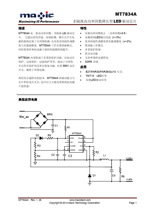
MT7834A 内部集成了功率因数校正电路,并且工 作在准谐振模式。输出 LED 电流可以通过检测电 感电流而被精准地调节。
控制回路的建立。一旦 COMP 脚电压达到 1.4V, 整个系统开始正常工作。
如果芯片 VDD 是由辅助绕组供电(请参考图 3) , LED 电压的过压阈值可以通过下式计算:
DRV
VOUT _OV 3.2 (1
Sampling Point
R3 N p ) R4 N a
其中, Np 是主级绕组的匝数, Na 是辅助绕组的匝 数。 通过设计合适的 R3, R4 电阻比值, 使得系统正常 工作时,DSEN 脚电压低于 2.7V。
D1
C4
R6
VLED-
MT7834A Rev. 1. 35
Copyright © 2014 Maxic Technology Corporation
Page 1
MT7834A
Maximizing IC Performance
非隔离高功率因数降压型 LED 驱动芯片
DSEN
LEB=2uS (typ)
图.2、反馈电压检测
短路保护
如果 DSEN 脚的电压在 5 到 10mS 内连续小于 400mV,短路保护就会被触发。然后 MT7834A 就 会进入打嗝模式。
打嗝模式
MT7834A 在检测到任何异常状态后,比如过压、 短路等,都会进入到打嗝模式,这时 PWM 脉冲信 号被关闭。因此 VDD 电压被 MT7834A 自身的静 态电流放电, 一直到 VDD 电压低于欠压保护阈值。 然后 MT7834A 进入下一个启动过程。 当异常的状 态消除后,MT7834A 就会在下一个启动过程之后 进入到正常的恒流控制模式,实现自恢复。 打嗝模式使系统在异常状态下保持极低的功耗, 从 而增强了系统的可靠性。
IRFS3307ZTRLPBF;IRFS3307ZPBF;IRFB3307ZPBF;IRFSL3307ZPBF;中文规格书,Datasheet资料
Coss
Output Capacitance
––– 4750 ––– ––– 420 –––
Crss
Reverse Transfer Capacitance
––– 190 –––
i Coss eff. (ER) Effective Output Capacitance (Energy Related) ––– 440 –––
PD - 97214D
Applications l High Efficiency Synchronous Rectification in
SMPS l Uninterruptible Power Supply l High Speed Power Switching l Hard Switched and High Frequency Circuits
g V TJ = 25°C, IS = 75A, VGS = 0V
––– 33 50 ns TJ = 25°C
VR = 64V,
––– 39 59
TJ = 125°C
––– 42 63 nC TJ = 25°C
g IF = 75A
di/dt = 100A/μs
––– 56 84
TJ = 125°C
––– 2.2 ––– A TJ = 25°C
Continuous Drain Current, VGS @ 10V (Silicon Limited) Continuous Drain Current, VGS @ 10V (Silicon Limited)
d Continuous Drain Current, VGS @ 10V (Wire Bond Limited)
some lead mounting arrangements.
IRF7304中文资料

IRF7304HEXFET ®Power MOSFETPD - 9.1240BDescriptionPRELIMINARYAbsolute Maximum RatingsSO-8Thermal Resistance** When mounted on 1" square PCB (FR-4 or G-10 Material).For recommended footprint and soldering techniques refer to application note #AN-994.Generation V Technology Ultra Low On-Resistance Dual P-Channel Mosfet Surface MountAvailable in Tape & Reel Dynamic dv/dt Rating Fast Switching Fifth Generation HEXFETs from International Rectifier utilize advanced processing techniques to achieve the lowest possible on-resistance per silicon area. This benefit, combined with the fast switching speed and ruggedized device design for which HEXFET Power MOSFETs are well known, provides the designer with an extremely efficient device for use in a wide variety of applications.The SO-8 has been modified through a customized leadframe for enhanced thermal characteristics and multiple-die capability making it ideal in a variety of power applications. With these improvements, multiple devices can be used in an application with dramatically reduced board space. The package is designed for vapor phase, infra-red, or wave soldering techniques. Power dissipation of greater than 0.8W is possible in a typical PCB mount application.V DSS = -20V R DS(on) = 0.090ΩParameterMin.Typ.Max.UnitsR θJAJunction-to-Amb. (PCB Mount, steady state)**––––––––90°C/W127Source-Drain Ratings and CharacteristicsIntrinsic turn-on time is negligible (turn-on is dominated by L S +L D )A。
IR公司_大功率MOS管选型

I DContinuous Drain Current(A)70°Micro3Surface Mount PackagesV (BR)DSSDrain-to-Source Breakdown Voltage (V)R DS(on)On-State Resistance ()ΩI D Continuous Drain Current 25°C(A)R ΘMax.Thermal Resistance (°C/W)1FaxonDemand Number Case Outline KeyPartNumberPD Max.PowerDissipation (W)N-ChannelLogic LevelIRLML2402*912570.54200.25 1.20.95230H1IRLML2803912580.54300.251.20.93230P-ChannelLogic LevelIRLML6302*912590.54-200.6-0.62-4.8230H1IRLML5103912600.54-300.6-0.61-4.8230* Indicates low VGS(th), which can operate at VGS = 2.7VMeasured at ambient for Micro3, Micro6, Micro8, SO-8, and SOT-223 package styles. All others measured at case.1Micro3SO-8D-PakD -PakSOT-227Micro6SOT-223Micro82 Illustrations not to scaleI DContinuous Drain Current(A)70°Micro6Surface Mount PackagesV (BR)DSSDrain-to-Source Breakdown Voltage (V)R DS(on)On-State Resistance ()ΩI D Continuous Drain Current 25°C(A)R ΘMax.Thermal Resistance (°C/W)1FaxonDemand Number Case Outline KeyPartNumberPD Max.PowerDissipation (W)N-ChannelLogic LevelIRLMS1902915401.7200.10 3.2 2.675H2IRLMS1503915081.7300.103.22.675P-ChannelLogic LevelIRLMS6702*914141.7-200.20-2.3-1.975H2IRLMS5703914131.7-300.20-2.3-1.975* Indicates low VGS(th), which can operate at VGS = 2.7VMeasured at ambient for Micro3, Micro6, Micro8, SO-8, and SOT-223 package styles. All others measured at case.1Micro3SO-8D-PakD -PakSOT-227Micro6SOT-223Micro82 Illustrations not to scaleI DContinuous Drain Current(A)70°Micro8Surface Mount PackagesV (BR)DSSDrain-to-Source Breakdown Voltage (V)R DS(on)On-State Resistance ()ΩI D Continuous Drain Current 25°C(A)R ΘMax.Thermal Resistance (°C/W)1FaxonDemand Number Case Outline KeyPart NumberP D Max.PowerDissipation (W)N-Channel Logic LevelIRF7601* 912611.820 0.035 5.7 4.6 70 H3IRF7603 912621.830 0.035 5.6 4.5 70Dual N-Channel Logic LevelIRF7501* 912651.220 0.135 2.4 1.9 100 H3IRF7503 912661.2530 0.135 2.4 1.9 100P-Channel Logic LevelIRF7604* 912631.8-20 0.09 -3.6 -2.9 70 H3IRF7606 912641.8-30 0.09 -3.6 -2.9 70Dual P-Channel Logic LevelIRF7504* 912671.25-20 0.27 -1.7 -1.4 100 H3IRF7506 912681.25-30 0.27 -1.7 -1.4 100Dual N- and P-Channel Logic LevelIRF7507* 912691.2520 0.1352.4 1.9 100 H3-20 0.27 -1.7 -1.4IRF7509 912701.2530 0.135 2.4 1.9 100-30 0.27 -1.7 -1.4* Indicates low VGS(th), which can operate at VGS = 2.7VMeasured at ambient for Micro3, Micro6, Micro8, SO-8, and SOT-223 package styles. All others measured at case.1Micro3SO-8D-Pak D -PakSOT-227Micro6SOT-223Micro8 2 Illustrations not to scaleI DContinuous Drain Current(A)70°SO-8Surface Mount PackagesV (BR)DSSDrain-to-Source Breakdown Voltage (V)R DS(on)On-State Resistance ()ΩI D Continuous Drain Current 25°C(A)R ΘMax.Thermal Resistance (°C/W)1FaxonDemand Number Case Outline KeyPart Number P D Max.PowerDissipation (W)N-ChannelIRF7413913302.5300.011139.250H4IRF7413A 916132.5300.0135128.450IRF9410915622.5300.0375.850Dual N-ChannelIRF7311914352.0200.029 6.6 5.362.5H4IRF7313914802.0300.029 6.5 5.262.5IRF7333917002.0300.10 3.5 2.862.5917002.0300.050 4.9 3.962.5IRF9956915592.0300.103.52.862.5Dual P-ChannelIRF7314914352.0-200.058-5.3-4.362.5H4IRF7316915052.0-300.058-4.9-3.962.5IRF9953915602.0-300.25-2.3-1.862.5* Indicates low VGS(th), which can operate at VGS = 2.7VMeasured at ambient for Micro3, Micro6, Micro8, SO-8, and SOT-223 package styles. All others measured at case.1Micro3SO-8D-PakD -PakSOT-227Micro6SOT-223Micro82 Illustrations not to scaleI DContinuous Drain Current(A)70°SO-8Surface Mount PackagesV (BR)DSSDrain-to-Source Breakdown Voltage (V)R DS(on)On-State Resistance ()ΩI D Continuous Drain Current 25°C(A)RΘMax.ThermalResistance(°C/W)1FaxonDemand Number Case Outline KeyPart NumberP D Max.PowerDissipation (W)Dual N- and P-ChannelIRF7317 915682.020 0.029 6.6 5.3 62.5 H42.0-20 0.058 -5.3 -4.3 62.5IRF9952 915622.030 0.103.5 2.8 62.5915622.0-30 0.25 -2.3 -1.8 62.5IRF7319 916062.030 0.029 6.5 5.2 62.52.0-30 0.058 -4.9 -3.9 62.5* Indicates low VGS(th), which can operate at VGS = 2.7VMeasured at ambient for Micro3, Micro6, Micro8, SO-8, and SOT-223 package styles. All others measured at case.1Micro3SO-8D-Pak D -PakSOT-227Micro6SOT-223Micro8 2 Illustrations not to scaleI DContinuous Drain Current(A)70°SO-8Surface Mount PackagesV (BR)DSSDrain-to-Source Breakdown Voltage (V)R DS(on)On-State Resistance ()ΩI D Continuous Drain Current 25°C(A)R ΘMax.Thermal Resistance (°C/W)1FaxonDemand Number Case Outline KeyPart Number P D Max.PowerDissipation (W)N-ChannelLogic LevelIRF7401912442.5200.0228.77.050H4IRF7201911002.5300.0307.0 5.650IRF7403912452.5300.0228.55.450Dual N-ChannelLogic LevelIRF7101908712.0200.10 3.5 2.362.5H4IRF7301912382.0200.050 5.2 4.162.5IRF7303912392.0300.050 4.9 3.962.5IRF7103910952.0500.1303.02.362.5P-ChannelLogic LevelIRF7204911032.5-200.060-5.3-4.250H4IRF7404912462.5-200.040-6.7-5.450IRF7205911042.5-300.070-4.6-3.750IRF7406912472.5-300.045-5.8-3.750IRF7416913562.5-300.02-10-7.150* Indicates low VGS(th), which can operate at VGS = 2.7VMeasured at ambient for Micro3, Micro6, Micro8, SO-8, and SOT-223 package styles. All others measured at case.1Micro3SO-8D-PakD -PakSOT-227Micro6SOT-223Micro82 Illustrations not to scaleI DContinuous Drain Current(A)70°SO-8Surface Mount PackagesV (BR)DSSDrain-to-Source Breakdown Voltage (V)R DS(on)On-State Resistance ()ΩI D Continuous Drain Current 25°C(A)R ΘMax.Thermal Resistance (°C/W)1FaxonDemand Number Case Outline KeyPart Number P D Max.PowerDissipation (W)Dual P-ChannelLogic LevelIRF7104910962.0-200.250-2.3-1.862.5H4IRF7304912402.0-200.090-4.3-3.462.5IRF7306912412.0-300.10-3.6-2.962.5Dual N- and P-Channe Logic LevelIRF7307912421.4200.050 4.3 3.490H4-200.090-3.6-2.9IRF7105910972.0250.1093.5 2.862.52-250.25-2.3-1.862IRF7309912432.0300.050 4.9 3.962.5-300.10-3.6-2.9* Indicates low VGS(th), which can operate at VGS = 2.7VMeasured at ambient for Micro3, Micro6, Micro8, SO-8, and SOT-223 package styles. All others measured at case.1Micro3SO-8D-PakD -PakSOT-227Micro6SOT-223Micro82 Illustrations not to scaleI DContinuous Drain Current(A)70°SOT-223Surface Mount PackagesV (BR)DSSDrain-to-Source Breakdown Voltage (V)R DS(on)On-State Resistance ()ΩI D Continuous Drain Current 25°C(A)R ΘMax.Thermal Resistance (°C/W)1FaxonDemand Number Case Outline KeyPart Number P D Max.PowerDissipation (W)N-ChannelIRFL4105913812.1550.045 3.7 3.060H6IRFL110908612.01000.54 1.50.9660IRFL4310913682.11000.20 1.6 1.360IRFL21090868 2.02001.50.960.660IRFL214908622.02502.00.790.560P-ChannelIRFL9110908642.0-1001.2-1.1-0.6960H6N-ChannelLogic LevelIRLL3303913792.1300.031 4.6 3.760H6IRLL014N 914992.1550.14 2.0 1.660IRLL2705913802.1550.043.83.060* Indicates low VGS(th), which can operate at VGS = 2.7VMeasured at ambient for Micro3, Micro6, Micro8, SO-8, and SOT-223 package styles. All others measured at case.1Micro3SO-8D-PakD -PakSOT-227Micro6SOT-223Micro82 Illustrations not to scaleI DContinuous Drain Current(A)100°D-PakSurface Mount PackagesV (BR)DSSDrain-to-Source Breakdown Voltage (V)R DS(on)On-State Resistance ()ΩI D Continuous Drain Current 25°C(A)R ΘMax.Thermal Resistance (°C/W)1FaxonDemand Number Case Outline KeyPart Number P D Max.PowerDissipation (W)N-ChannelIRFR33039164257300.0313321 2.2H7IRFR024N9133638550.0751610 3.3IRFR41059130248550.0452516 2.7IRFR12059131869550.0273723 1.8IRFR11090524251000.54 4.3 2.75IRFR120N 91365391000.219.1 5.8 3.2IRFR391091364521000.11159.5 2.4IRFR2109052625200 1.5 2.6 1.75IRFR22090525422000.8 4.833IRFR21490703252502 2.2 1.45IRFR2249060042250 1.1 3.8 2.43IRFR3109059725400 3.6 1.7 1.15IRFR3209059842400 1.8 3.123IRFR42090599425003 2.4 1.53IRFRC2090637426004.421.33* Indicates low VGS(th), which can operate at VGS = 2.7VMeasured at ambient for Micro3, Micro6, Micro8, SO-8, and SOT-223 package styles. All others measured at case.1Micro3SO-8D-PakD -PakSOT-227Micro6SOT-223Micro82 Illustrations not to scaleI DContinuous Drain Current(A)100°D-PakSurface Mount PackagesV (BR)DSSDrain-to-Source Breakdown Voltage (V)R DS(on)On-State Resistance ()ΩI D Continuous Drain Current 25°C(A)R ΘMax.Thermal Resistance (°C/W)1FaxonDemand Number Case Outline KeyPart Number P D Max.PowerDissipation (W)P-ChannelIRFR55059161057-550.11-18-11 2.2H7IRFR53059140289-550.065-28-18 1.4IRFR90149065425-600.5-5.1-3.25IRFR90249065542-600.28-8.8-5.63IRFR91109051925-100 1.2-3.1-25IRFR91209052042-1000.6-5.6-3.63IRFR9120N 9150739-1000.48-6.5-4.1 3.2IRFR92109052125-2003-1.9-1.25IRFR92209052242-200 1.5-3.6-2.33IRFR92149165850-250 3.0-2.7-1.7 2.5IRFR93109166350-4007.0-1.8-1.12.5* Indicates low VGS(th), which can operate at VGS = 2.7VMeasured at ambient for Micro3, Micro6, Micro8, SO-8, and SOT-223 package styles. All others measured at case.1Micro3SO-8D-PakD -PakSOT-227Micro6SOT-223Micro82 Illustrations not to scaleI DContinuous Drain Current(A)100°D-PakSurface Mount PackagesV (BR)DSSDrain-to-Source Breakdown Voltage (V)R DS(on)On-State Resistance ()ΩI D Continuous Drain Current 25°C(A)R ΘMax.Thermal Resistance (°C/W)1FaxonDemand Number Case Outline KeyPart Number P D Max.PowerDissipation (W)N-ChannelLogic LevelIRLR27039133538300.0452214 3.3H7IRLR33039131657300.0313321 2.2IRLR31039133369300.0194629 1.8IRLR024N 9136338550.0651711 3.3IRLR27059131746550.042415 2.7IRLR29059133469550.0273623 1.8IRLR120N 91541391000.18511 6.9 3.2IRLR341091607521000.10159.52.4* Indicates low VGS(th), which can operate at VGS = 2.7VMeasured at ambient for Micro3, Micro6, Micro8, SO-8, and SOT-223 package styles. All others measured at case.1Micro3SO-8D-PakD -PakSOT-227Micro6SOT-223Micro82 Illustrations not to scaleI DContinuous Drain Current(A)100°D 2PakSurface Mount PackagesV (BR)DSSDrain-to-Source Breakdown Voltage (V)R DS(on)On-State Resistance ()ΩI D Continuous Drain Current 25°C(A)R ΘMax.Thermal Resistance (°C/W)1FaxonDemand Number Case Outline KeyPart NumberP D Max.PowerDissipation (W)N-ChannelIRFZ24NS 913554555 0.07 17 12 3.3 H10IRFZ34NS 913116855 0.04 29 20 2.2IRFZ44NS 9131511055 0.022 49 35 1.4IRFZ46NS 9130512055 0.020 53 37 1.3IRFZ48NS 9140814055 0.016 64 45 1.1IRF1010NS 913723.855 0.011 84 60 40IRF3205S 9130420055 0.008 110 80 0.75IRFZ44ES 9171411060 0.023 48 34 1.4IRF1010ES 9172017060 0.012 83 59 0.90IRF2807S 9151815075 0.013 71 50 1.0IRF520NS 9134047100 0.2 9.5 6.7 3.2IRF530NS 9135263100 0.11 15 11 2.4IRF540NS 91342110100 0.052 27 19 1.6IRF1310NS 91514120100 0.036 36 25 1.3IRF3710S 91310150100 0.028 46 33 1.0IRF3315S 9161794150 0.082 21 15 1.6IRF3415S 91509150150 0.042 37 26 1.0IRFBC20S 9.101450600 4.4 2.2 1.4 2.5IRFBC30S 9101574600 2.2 3.6 2.3 1.7IRFBC40S 91016130600 1.2 6.2 3.9 1.0* Indicates low VGS(th), which can operate at VGS = 2.7VMeasured at ambient for Micro3, Micro6, Micro8, SO-8, and SOT-223 package styles. All others measured at case.1Micro3SO-8D-Pak D -PakSOT-227Micro6SOT-223Micro8 2 Illustrations not to scaleI DContinuous Drain Current(A)100°D 2PakSurface Mount PackagesV (BR)DSSDrain-to-Source Breakdown Voltage (V)R DS(on)On-State Resistance ()ΩI D Continuous Drain Current 25°C(A)R ΘMax.Thermal Resistance (°C/W)1FaxonDemandNumberCase Outline KeyPart NumberP D Max.PowerDissipation (W)IRFBF20S 9166554900 8.0 1.7 1.1 2.3 H10P-ChannelIRF5305S 91386110-55 0.06 -31 -22 1.4 H10IRF4905S 914783.8-55 0.02 -74 -52 40IRF9520NS 9152247-100 0.48 -6.7 -4.8 3.2IRF9530NS 9152375-100 0.20 -14 -9.9 2.0IRF9540NS 9148394-100 0.117 -19 -13 1.6IRF5210S 91405150-100 0.06 -35 -25 1.0* Indicates low VGS(th), which can operate at VGS = 2.7VMeasured at ambient for Micro3, Micro6, Micro8, SO-8, and SOT-223 package styles. All others measured at case.1Micro3SO-8D-Pak D -PakSOT-227Micro6SOT-223Micro8 2 Illustrations not to scaleI DContinuous Drain Current(A)100°D 2PakSurface Mount PackagesV (BR)DSSDrain-to-Source Breakdown Voltage (V)R DS(on)On-State Resistance ()ΩI D Continuous Drain Current 25°C(A)R ΘMax.Thermal Resistance (°C/W)1FaxonDemand Number Case Outline KeyPart NumberP D Max.PowerDissipation (W)N-Channel Logic LevelIRL3302S 916925720 0.020 39 25 2.2 H10IRL3202S916756920 0.016 48 30 1.8IRL3102S 916918920 0.013 61 39 1.4IRL3402S 9169311020 0.01 85 54 1.1IRL3502S 9167614020 0.007 110 67 0.89IRL2703S 913604530 0.04 24 17 3.3IRL3303S 913236830 0.026 38 27 2.2IRL3103S 9133811030 0.014 64 45 1.4IRL2203NS 9136717030 0.007 116 82 0.90IRL3803S 9131920030 0.006 140 98 0.75IRLZ24NS 913584555 0.06 18 13 3.3IRLZ34NS 913086855 0.035 30 21 2.2IRLZ44NS 9134711055 0.022 47 33 1.4IRL3705NS 9150217055 0.01 89 63 0.90IRL2505S 9132620055 0.008 104 74 0.75IRLZ44S 9090615060 0.028 50 36 1.0IRL530NS 9134963100 0.1 15 11 2.4IRL2910S 91376150100 0.026 48 34 1.0* Indicates low VGS(th), which can operate at VGS = 2.7VMeasured at ambient for Micro3, Micro6, Micro8, SO-8, and SOT-223 package styles. All others measured at case.1Micro3SO-8D-Pak D -PakSOT-227Micro6SOT-223Micro8 2 Illustrations not to scaleI DContinuous Drain Current(A)100°SOT-227Surface Mount PackagesV (BR)DSSDrain-to-Source Breakdown Voltage (V)R DS(on)On-State Resistance ()ΩI D Continuous DrainCurrent 25°C(A)RΘMax.Thermal Resistance (°C/W)1FaxonDemand Number Case Outline KeyPart Number P D Max.PowerDissipation (W)N-ChannelFully Isolated Low ChargeFA38SA50LC 916155005000.1338240.25H21FA57SA50LC916506255000.0857360.20* Indicates low VGS(th), which can operate at VGS = 2.7VMeasured at ambient for Micro3, Micro6, Micro8, SO-8, and SOT-223 package styles. All others measured at case.1Micro3SO-8D-PakD -PakSOT-227Micro6SOT-223Micro82 Illustrations not to scaleI DContinuous Drain Current(A)100°I-PakThrough-Hole PackagesV (BR)DSSDrain-to-Source Breakdown Voltage (V)R DS(on)On-State Resistance ()ΩI D Continuous Drain Current 25°C(A)R ΘMax.Thermal Resistance (°C/W)1FaxonDemand Number Case Outline KeyPart Number P D Max.PowerDissipation (W)N-ChannelIRFU33039164257300.0313321 2.2H8IRFU024N 9133638550.0751610 3.3IRFU41059130248550.0452519 2.7IRFU12059131869550.0273723 1.8IRFU11090524251000.54 4.3 2.7 5.0IRFU120N 91365391000.219.1 5.8 3.2IRFU391091364521000.11159.5 2.4IRFU2109052625200 1.5 2.6 1.7 5.0IRFU22090525422000.80 4.8 3.0 3.0IRFU2149070325250 2.0 2.2 1.4 5.0IRFU2249060042250 1.1 3.8 2.4 3.0IRFU3109059725400 3.6 1.7 1.1 5.0IRFU3209059842400 1.8 3.1 2.0 3.0IRFU4209059942500 3.0 2.4 1.5 3.0IRFUC2090637426004.42.01.33.0I-PakTO-220 FullPakTO-262TO-247HEXDIPTO-220AB Illustrations not to scale** Not ratedI DContinuous Drain Current(A)100°I-PakThrough-Hole PackagesV (BR)DSSDrain-to-Source Breakdown Voltage (V)R DS(on)On-State Resistance ()ΩI D Continuous Drain Current 25°C(A)R ΘMax.Thermal Resistance (°C/W)1FaxonDemand Number Case Outline KeyPart Number P D Max.PowerDissipation (W)P-ChannelIRFU55059161057-550.11-18-11 2.2H8IRFU53059140289-550.065-28-18 1.4IRFU90149065425-600.50-5.1-3.2 5.0IRFU90249065542-600.28-8.8-5.6 3.0IRFU91109051925-100 1.2-3.1-2.0 5.0IRFU91209052042-1000.60-5.6-3.6 3.0IRFU9120N 9150739-1000.48-6.5-4.1 3.2IRFU92109052125-200 3.0-1.9-1.2 5.0IRFU92209052242-200 1.5-3.6-2.3 3.0IRFU92149165850-2503.0-2.7-1.7 2.5IRFU93109166350-4007.0-1.8-1.12.5N-ChannelLogic LevelIRLU27039133538300.0452214 3.3H8IRLU33039131657300.0313321 2.2IRLU31039133369300.0194629 1.8IRLU024N 9136338550.0651711 3.3IRLU27059131746550.04241715IRLU29059133469550.0273623 1.8IRLU120N 91541391000.18511 6.9 3.2IRLU341091607521000.10159.52.4I-PakTO-220 FullPakTO-262TO-247HEXDIPTO-220AB Illustrations not to scale** Not ratedI DContinuous Drain Current(A)100°HEXDIPThrough-Hole PackagesV (BR)DSSDrain-to-Source Breakdown Voltage (V)R DS(on)On-State Resistance ()ΩI D Continuous Drain Current 25°C(A)R ΘMax.Thermal Resistance (°C/W)1FaxonDemand Number Case Outline KeyPart Number P D Max.PowerDissipation (W)N-ChannelIRFD014907001.3600.2 1.7 1.2120H9IRFD024906991.3600.1 2.5 1.8120IRFD110903281.31000.54 1.00.71120IRFD120903851.31000.27 1.30.94120IRFD210903861.3200 1.50.60.38120IRFD220904171.32000.80.80.50120IRFD214912711.3250 2.00.570.32120IRFD224912721.3250 1.10.760.43120IRFD310912251.3400 3.60.420.23120IRFD320912261.3400 1.80.600.33120IRFD420912271.3500 3.00.460.26120IRFDC20912281.36004.40.320.21120I-PakTO-220 FullPakTO-262TO-247HEXDIPTO-220AB Illustrations not to scale** Not ratedI D Continuous Drain Current (A)100°TO-220Qg TotalGate Charge(nC)Through-Hole PackagesV (BR)DSSDrain-to-Source Breakdown Voltage (V)R DS(on)On-State Resistance ()ΩI D Continuous Drain Current 25°C (A)R ΘMax.Thermal Resistance(°C/W)1Faxon Demand Number Case OutlineKeyPart Number P D Max.Power Dissipation (W)N-ChannelLow ChargeIRF737LC91314743000.75 6.1** 1.7 3.9H11IRF740LC 910681254000.5510** 1.039IRF840LC 910691255000.858.0** 1.039IRFBC40LC910701256001.26.2**1.039I-PakTO-220 FullPakTO-262TO-247HEXDIPTO-220AB Illustrations not to scale** Not ratedI DContinuous Drain Current(A)100°TO-220ABThrough-Hole PackagesV (BR)DSSDrain-to-Source Breakdown Voltage (V)R DS(on)On-State Resistance ()ΩI D Continuous Drain Current 25°C(A)R ΘMax.Thermal Resistance (°C/W)1FaxonDemand Number Case Outline KeyPart Number P D Max.PowerDissipation (W)N-ChannelIRFZ24N 9135445550.071712 3.3H12IRFZ34N9127656550.042618 2.7IRFZ44N 9130383550.0244129 1.8IRFZ46N 9127788550.024633 1.7IRFZ48N 9140694550.0165337 1.6IRF1010N 91278130550.0127251 1.2IRF320591279150550.0089869 1.0IRFZ34E 9167268600.0422820 2.2IRFZ44E 91671110600.0234834 1.4IRF1010E 91670170600.01281570.90IRF280791517150750.0137150 1.0IRF520N 91339471000.209.5 6.79.5IRF530N 91351601000.111511 2.4IRF540N 91341941000.0522719 1.6IRF1310N 916111201000.0363625 1.3IRF3710913091501000.0284633 1.0IRF331591623941500.0822115 1.6IRF3415914771501500.0423726 1.0IRFBC209062350600 4.4 2.2 1.4 2.5IRFBC309048274600 2.2 3.6 2.3 1.7IRFBC4090506125600 1.2 6.2 3.9 1.0IRFBE2090610548006.51.81.22.3I-PakTO-220 FullPakTO-262TO-247HEXDIPTO-220AB Illustrations not to scale** Not ratedI DContinuous Drain Current(A)100°TO-220ABThrough-Hole PackagesV (BR)DSSDrain-to-Source Breakdown Voltage (V)R DS(on)On-State Resistance ()ΩI D Continuous Drain Current 25°C(A)R ΘMax.Thermal Resistance (°C/W)1FaxonDemand Number Case Outline KeyPart Number P D Max.PowerDissipation (W)IRFBE3090613125800 3.0 4.1 2.6 2.0H12IRFBF3090616125900 3.7 3.6 2.3 1.0IRFBG209060454100011 1.40.86 2.3IRFBG309062012510005.03.12.01.0P-ChannelIRF9Z24N 9148445-550.175-12-8.53.3H12IRF9Z34N 9148556-550.10-17-12 2.7IRF530591385110-550.06-31-22 1.4IRF490591280150-550.02-64-45 1.0IRF9530N 9148275-1000.20-13-9.2 2.0IRF9540N 9143794-1000.117-19-13 1.6IRF521091434150-1000.06-35-25 1.0IRF62159147983-1500.29-11-7.81.8I-PakTO-220 FullPakTO-262TO-247HEXDIPTO-220AB Illustrations not to scale** Not ratedI DContinuous Drain Current(A)100°TO-220ABThrough-Hole PackagesV (BR)DSSDrain-to-Source Breakdown Voltage (V)R DS(on)On-State Resistance ()ΩI D Continuous Drain Current 25°C(A)R ΘMax.Thermal Resistance (°C/W)1FaxonDemand Number Case Outline KeyPart NumberP D Max.PowerDissipation (W)N-Channel Logic LevelIRL3302 916965720 0.020 39 25 2.2 H12IRL3202 916956920 0.016 48 30 1.8IRL3102 916948920 0.013 61 39 1.4IRL3402 9169711020 0.01 85 54 1.1IRL3502 9169814020 0.007 110 67 0.89IRL2703 913594530 0.04 24 17 3.3IRL3303 913225630 0.026 34 24 2.7IRL3103 913378330 0.014 56 40 1.8IRL2203N 9136613030 0.007 100 71 1.230 0.007 61 43 3.2IRL3803 9130115030 0.006 120 83 1.0IRLZ24N 913574555 0.06 18 13 3.3IRLZ34N 913075655 0.035 27 19 2.7IRLZ44N 913468355 0.022 41 29 1.8IRL3705N 9137013055 0.01 77 54 1.2IRL2505 9132520055 0.008 104 74 0.75IRL520N 9149447100 0.18 10 7.1 3.2IRL530N 9134863100 0.10 15 11 2.4IRL540N 9149594100 0.044 30 21 1.6IRL2910 91375150100 0.026 48 34 1.0I-PakTO-220 FullPakTO-262TO-247HEXDIPTO-220AB Illustrations not to scale** Not ratedI D Continuous Drain Current (A)100°TO-220 FullPak (Fully Isolated)Qg TotalGate Charge(nC)Through-Hole PackagesV (BR)DSSDrain-to-Source Breakdown Voltage (V)R DS(on)On-State Resistance ()ΩI D Continuous DrainCurrent 25°C(A)R ΘMax.Thermal Resistance (°C/W)1Fax on Demand Number Case OutlineKeyPart Number P D Max.Power Dissipation (W)N-ChannelLow ChargeIRFI740GLC91209404000.55 6.0** 3.139H13IRFI840GLC 91208405000.85 4.8** 3.139IRFIBC40GLC91211406001.24.0**3.139I-PakTO-220 FullPakTO-262TO-247HEXDIPTO-220AB Illustrations not to scale** Not ratedI DContinuous Drain Current(A)100°TO-220 FullPak (Fully Isolated)Through-Hole PackagesV (BR)DSSDrain-to-Source Breakdown Voltage (V)R DS(on)On-State Resistance ()ΩI D Continuous Drain Current 25°C(A)R ΘMax.Thermal Resistance (°C/W)1FaxonDemand Number Case Outline KeyPart Number P D Max.PowerDissipation (W)N-ChannelIRFIZ24N 9150126550.07139.2 5.8H14IRFIZ34N9148931550.041913 4.8IRFIZ44N 9140338550.02428200.024IRFIZ46N 9130640550.023122 3.8IRFIZ48N 9140742550.0163625 3.6IRFI1010N 9137347550.0124431 3.2IRFI32059137448550.0085640 3.1IRFIZ24E 9167329600.071149.6 5.2IRFIZ34E 9167437600.0422115 4.1IRFI510G 90829271000.54 4.5 3.2 5.5IRFI520N 91362271000.207.2 5.1 5.5IRFI530N 91353331000.11117.8 4.5IRFI540N 91361421000.0521813 3.6IRFI1310N 91611451000.0362216 3.3IRFI371091387481000.0252820 3.1IRFI620G 90832302000.8 4.1 2.6 4.1IRFI630G 90652322000.4 5.9 3.7 3.6IRFI640G 90649402000.189.8 6.2 3.1IRFI614G 9083123250 2.0 2.1 1.3 5.5IRFI624G 9083330250 1.1 3.4 2.2 4.1IRFI634G 90738322500.45 5.6 3.5 3.6IRFI644G 90739402500.287.953.1I-PakTO-220 FullPakTO-262TO-247HEXDIPTO-220AB Illustrations not to scale** Not ratedI DContinuous Drain Current(A)100°TO-220 FullPak (Fully Isolated)Through-Hole PackagesV (BR)DSSDrain-to-Source Breakdown Voltage (V)R DS(on)On-State Resistance ()ΩI D Continuous Drain Current 25°C(A)R ΘMax.Thermal Resistance (°C/W)1FaxonDemand Number Case Outline KeyPart Number P D Max.PowerDissipation (W)IRFI720G 9083430400 1.8 2.6 1.7 4.1H14IRFI730G 9065032400 1.0 3.7 2.3 3.6IRFI740G 90651404000.55 5.4 3.4 3.1IRFI734G 9100135450 1.2 3.4 2.1 3.6IRFI744G 91002404500.63 4.9 3.1 3.1IRFI820G 9064130500 3.0 2.1 1.3 4.1IRFI830G 9064632500 1.5 3.12 3.6IRFI840G 90642405000.85 4.6 2.9 3.1IRFIBC20G 90850306004.41.71.1 4.1IRFIBC30G 90851356002.2 2.5 1.63.6IRFIBC40G 9085240600 1.2 3.5 2.2 3.1IRFIBE20G 9085330800 6.5 1.4.86 4.1IRFIBE30G 9085435800 3.0 2.1 1.4 3.6IRFIBF20G 90855309008.0 1.2.79 4.1IRFIBF30G90856359003.71.91.23.6P-ChannelIRFI9Z24N 9152929-550.175-9.5-6.7 5.2H14IRFI9Z34N 9153037-550.10-14-10 4.1IRFI49059152663-550.02-41-29 2.4IRFI9540G 9083742-1000.117-13-9.2 3.6IRFI9540N 9148742-1000.117-13-9.2 3.6IRFI52109140448-1000.06-20-14 3.1IRFI9634G 9148835-2501.0-4.1-2.63.6I-PakTO-220 FullPakTO-262TO-247HEXDIPTO-220AB Illustrations not to scale** Not ratedI DContinuous Drain Current(A)100°TO-220 FullPak (Fully Isolated)Through-Hole PackagesV (BR)DSSDrain-to-Source Breakdown Voltage (V)R DS(on)On-State Resistance ()ΩI D Continuous Drain Current 25°C(A)R ΘMax.Thermal Resistance (°C/W)1FaxonDemand Number Case Outline KeyPart Number P D Max.PowerDissipation (W)N-ChannelLogic LevelIRLI2203N 9137847300.0076143 3.2H14IRLI38039132048300.0066747 3.1IRLIZ24N 9134426550.06149.9 5.8IRLIZ34N 9132931550.0352014 4.8IRLIZ44N 9149838550.0222820 4.0IRLI3705N 9136947550.014733 3.2IRLI25059132763550.00858412.4IRLI520N 91496271000.187.7 5.4 5.5IRLI530N 91350331000.10117.8 4.5IRLI540N 91497421000.04420143.6IRLI291091384481000.02627193.1P-ChannelLogic LevelIRFI9520G 9083537-1000.6-5.2-3.6 4.1H14IRFI9530G 9083638-1000.03-7.7-5.4 3.6IRFI9620G 9087430-200 1.5-3.0-1.9 4.1IRFI9630G 9083840-2000.8-4.3-2.7 3.6IRFI9640G9083940-2000.5-6.1-3.93.1I-PakTO-220 FullPakTO-262TO-247HEXDIPTO-220AB Illustrations not to scale** Not ratedI D Continuous Drain Current (A)100°TO-247Qg TotalGate Charge(nC)Through-Hole PackagesV (BR)DSSDrain-to-Source Breakdown Voltage (V)R DS(on)On-State Resistance ()ΩI D Continuous Drain Current 25°C (A)R ΘMax.Thermal Resistance (°C/W)1Fax on Demand Number Case OutlineKeyPart Number P D Max.Power Dissipation (W)1N-ChannelLow ChargeIRFP350LC912291904000.3018**0.6570H16IRFP360LC 912302804000.2023**0.4598IRFP450LC 912311905000.4016**0.6570IRFP460LC 912322805000.2720**0.4598IRFPC50LC 912331906000.6013**0.6570IRFPC60LC912342806000.4016**0.4598I-PakTO-220 FullPakTO-262TO-247HEXDIPTO-220AB Illustrations not to scale** Not rated。
逆变器用到的IC
KA5H0165RN 原装正品 06年份 FSC 4000 现货
FSDM0265RNB 原装正品 06年份 FSC 40000 香港现货
FSDL0165RN 原装正品 06年份 FSC 9000 香港现货
FSDH321 原装正品 06年份 FSC 12000 香港现货
STP10NK60 原装正品 04年份 ST 10000 现货
IRF640B 原装正品 04年份 FSC 3800 现货
IRF630B 原装正品 06年份 FSC 2000 现货
FDP2532 原装正品 06年份 FSC 4200 现货
FQP50N06 原装正品 07年份 FSC 20000 现货
SSH70N10A 原装正品 07年份 FSC 480 香港现货
FQA160N08 原装正品 06年份 FSC 1300 现货
FQA40N25 原装正品 05年份 FSC 340 现货
FQA16N50 原装正品 04年份 FSC 2600 现货
FQPF10N60C 原装正品 07年份 FSC 6000 现货
FQPF12N60C 原装正品 07年份 FSC 550 现货
KA5L0380RYDTU 原装正品 07年份 FSC 10000 香港现货
FQPF8N60C 原装正品 07年份 FSC 20000 香港现货
2SK2645 原装正品 06年份 FUJI 5400 现货
2SK2765 原装正品 06年份 FUJI 2500 现货
FQA90N15 原装正品 06年份 FSC 500 现货
IRFP460C 原装正品 06.07年份 FSC 5600 香港现货
irf7343
VGS , Gate-to-Source Voltage (V)
N-Ch P-Ch N-Ch P-Ch N-Ch P-Ch
24 36 26 38 2.3 3.4 3.0 4.5 7.0 10 8.4 13
nC
N-Channel ID = 4.5A, VDS = 44V, VGS = 10V
P-Channel ID = -3.1A, VDS = -44V, VGS = -10V
VDS = 55V, VGS = 0V
P-Ch N-Ch
-2.0 25
µA
VDS = -55V, VGS = 0V VDS = 55V, VGS = 0V, TJ = 55°C
P-Ch -25
VDS = -55V, VGS = 0V, TJ = 55°C
N-P ±100 nA VGS = ±20V
P-Ch -2.0 A
N-Ch 38
ISM
Pulsed Source Current (Body Diode)
P-Ch -27
VSD
Diode Forward Voltage
N-Ch 0.70 1.2 P-Ch -0.80 -1.2
V
TJ = 25°C, IS = 2.0A, VGS = 0V TJ = 25°C, IS = -2.0A, VGS = 0V
SO-8
Max.
N-Channel
P-Channel
55
-55
4.7
-3.4
3.8
-2.7
38
-27
2.0
1.3
72
114
4.7
-3.4
常见mos管
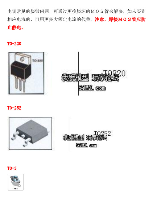
电调常见的烧毁问题,可通过更换烧坏的MOS管来解决,如未买到相应电流的,可用更多大额定电流的代替。
注意,焊接MOS管应防止静电。
TO-220TO-252TO-3附SO-8(贴片8脚)封装MOS管 IRF7805Z 的引脚图。
上图中有小圆点的为1脚注:下表按电流降序排列(如有未列出的,可回帖,我尽量补充)封装形式 极性 型号 电流(A) 耐压(V)导通电阻(m Ω)SO-8 N 型 SI4336 22 30 4.2 SO-8 N 型 IRF7831 21 30 3.6 SO-8 N 型 IRF7832 20 30 4 SO-8 N 型 IRF7822 18 30 SO-8 N 型 IRF7836 17 30 5.7 SO-8 N 型 IRF8113 17 30 5.6 SO-8 N 型 SI4404 17 30 8 SO-8 N 型 FDS6688 16 30 6SO-8 N型IRF8721 14 30 8.5 SO-8 N型IRF7805 13 30SO-8 N型IRF7805Q 13 30 11 SO-8 N型IRF7413 12 30 18 SO-8 N型TPC8003 12 30 6 SO-8 N型IRF7477 11 30 20 SO-8 N型IRF7811 11 30 12 SO-8 N型IRF7466 10 30 15 SO-8 N型SI4410 10 30 14 SO-8 N型SI4420 10 30 10 SO-8 N型A2700 9 30 7.3 SO-8 N型IRF7807 8.3 30SO-8 N型SI4812 7.3 30 28 SO-8 N型SI9410 6.9 30 50 SO-8 N型IRF7313 6 30 29 SO-8 P型SI4405 17 30 7.5 SO-8 P型STM4439A 14 30 18 SO-8 P型FDS6679 13 30 9 SO-8 P型SI4411 13 30 8 SO-8 P型SI4463 12.3 20 16 SO-8 P型SI4407 12 30SO-8 P型IRF7424 11 30 13.5 SO-8 P型IRF7416 10 30 20 SO-8 P型IRF7416Q 10 30 20 SO-8 P型SI4425 9 30 19 SO-8 P型IRF7424 8.8 30 22 SO-8 P型SI4435 8 30 20 SO-8 P型SI4435DY 8 30 20 SO-8 P型A2716 7 30 11.3 SO-8 P型IRF7406 5.8 30 45 SO-8 P型SI9435 5.3 30 50 SO-8 P型IRF7205 4.6 30 70 TO-252 N型FDD6688 84 30 5 TO-3 N型IRF150 40 100 55 TO-220 N型IRF3703 210 30 2.8 TO-220 N型IRL3803 140 30 6 TO-220 N型IRF1405 131 55 5.3 TO-220 N型IRF3205 110 55 8 TO-220 N型BUZ111S 80 55 8 TO-220 N型05N05 75 50 9.5 TO-220 N型IRF2804 75 40 2 TO-220 N型60N06 60 60 14 TO-220 N型50N03L 28 25 21TO-220 N型06N60 5.5 600 750MOS管应用电路设计本文来自: 原文网址:/sch/jcdl/0084942.htmlMOS管应用电路设计MOS管最显著的特性是开关特性好,所以被广泛应用在需要电子开关的电路中,常见的如开关电源和马达驱动,也有照明调光。
脉宽调制开关电源控制IC汇总

脉宽调制开关电源控制IC开关电源这个名字我们大家都不会感到很陌生。
常见的计算系统电源录象机、电视机电源都使用了这种电源技术。
但是常常会觉得这种电源技术好象很复杂根本不可能自已制作此类电源,当然早期的开关电源控制部份集成电路使得开关电源的外围变得如此简单以至于简单过一线性稳压电源。
这里介绍的是 sgs T开关电源这个名字我们大家都不会感到很陌生。
常见的计算系统电源录象机、电视机电源都使用了这种电源技术。
但是常常会觉得这种电源技术好象很复杂根本不可能自已制作此类电源,当然早期的开关电源控制部份集成电路使得开关电源的外围变得如此简单以至于简单过一线性稳压电源。
这里介绍的是 sgs Thomson 公司生产的新型系列集成稳压IC:UCX84X 之中的 UC1842 与系列中的其它 IC 相比,它们的内部电路结构基本上是一致的,只在某些参数如工作环境温度内部基准电压精度,最大占空比系数等方面有所区别所以原则上此类IC的外围电路是可以通用的。
UC1842 为脉冲调制 (PCM) 的开关电源控制 IC。
其封装为 8 脚,可谓简洁说明了。
其内部方框图如下:现介绍各脚功能:1脚为内部误差放大器输出端;2脚为误差放大输入端;1与2 脚之间接有反馈网络以确定反馈放大器增益与频响;2脚输入的反馈电压将与基准2.5V电压比较以产生控制电压;3脚为电流传感器输入引脚,当由电流传感器送来的电压超过1V时及当开关管过流时调宽脉冲就停止输出这样就保护了开关管防止意外损坏。
4脚为接定时电阻电容端口。
由外接的电容电阻决定内部振荡器振荡频率:f=1.8/Rt*Ct;5脚为接地端;6脚为输出调宽脉冲端口,输出的脉冲是推动后的开关管。
其驱动很强,达到 +1A 或 -1A 。
在负载叫容为 1000pF 时上升下降时间仅为 500S,所以很适合于推动VMOS管7脚为电源电压输入端,供电电压可在10V-30V,当电压低于10V时停止工作,工作电流 15mA,功耗是非常小的,因此工作稳定。
- 1、下载文档前请自行甄别文档内容的完整性,平台不提供额外的编辑、内容补充、找答案等附加服务。
- 2、"仅部分预览"的文档,不可在线预览部分如存在完整性等问题,可反馈申请退款(可完整预览的文档不适用该条件!)。
- 3、如文档侵犯您的权益,请联系客服反馈,我们会尽快为您处理(人工客服工作时间:9:00-18:30)。
3
IRF7834
100000 C rss = C gd C oss = C ds + C gd
VGS, Gate-to-Source Voltage (V)
VGS = 0V, f = 1 MHZ C iss = C gs + C gd, C ds SHORTED
12 ID= 16A 10 8 6 4 2 0 VDS= 24V VDS= 15V
Min. Typ. Max. Units
30 ––– ––– ––– 1.35 ––– ––– ––– ––– ––– 85 ––– ––– ––– ––– ––– ––– ––– ––– ––– ––– ––– ––– ––– ––– ––– 0.023 3.6 4.4 ––– - 5.2 ––– ––– ––– ––– ––– 29 7.5 2.7 9.8 9.0 12.5 19 13.7 14.3 18 5.0 3710 810 350 ––– ––– 4.5 5.5 2.25 ––– 1.0 150 100 -100 ––– 44 ––– ––– ––– ––– ––– ––– ––– ––– ––– ––– ––– ––– ––– pF VGS = 0V VDS = 15V ns nC nC VDS = 15V VGS = 4.5V ID = 16A S nA V mV/°C µA V mΩ
Fig 9. Maximum Drain Current Vs. Case Temperature
Fig 10. Threshold Voltage Vs. Temperature
Ã
e
e
2
IRF7834
1000
VGS TOP 10V 4.5V 3.8V 3.5V 3.3V 3.0V 2.8V BOTTOM 2.5V
1000
VGS 10V 4.5V 3.8V 3.5V 3.3V 3.0V 2.8V BOTTOM 2.5V TOP
ID, Drain-to-Source Current (A)
Max.
30 ± 20 19 16 160 2.5 1.6 0.02 -55 to + 150
Units
V
f Power Dissipation f
Power Dissipation
c
A W
Linear Derating Factor Operating Junction and Storage Temperature Range
Min. Typ. Max. Units
––– ––– ––– ––– ––– ––– ––– ––– 21 13 3.1 A 160 1.0 32 20 V ns nC
Conditions
MOSFET symbol showing the integral reverse p-n junction diode. TJ = 25°C, IS = 16A, VGS = 0V TJ = 25°C, IF = 16A, VDD = 15V di/dt = 100A/µs
ID , Drain Current (A)
1.8
12
ID = 250µA
1.4
8
4
0 25 50 75 100 125 150
1.0 -75 -50 -25 0 25 50 75 100 125 150
T J , Junction Temperature (°C)
T J , Temperature ( °C )
d
Typ. ––– –––
Max. 25 16
Units mJ A
Diode Characteristics
Parameter
IS ISM VSD trr Qrr Continuous Source Current (Body Diode) Pulsed Source Current (Body Diode) Diode Forward Voltage Reverse Recovery Time Reverse Recovery Charge
1
2/26/04
IRF7834
Static @ TJ = 25°C (unless otherwise specified)
Parameter
BVDSS ∆ΒVDSS/∆TJ RDS(on) VGS(th) ∆VGS(th) IDSS IGSS gfs Qg Qgs1 Qgs2 Qgd Qgodr Qsw Qoss td(on) tr td(off) tf Ciss Coss Crss Drain-to-Source Breakdown Voltage Breakdown Voltage Temp. Coefficient Static Drain-to-Source On-Resistance Gate Threshold Voltage Gate Threshold Voltage Coefficient Drain-to-Source Leakage Current Gate-to-Source Forward Leakage Gate-to-Source Reverse Leakage Forward Transconductance Total Gate Charge Pre-Vth Gate-to-Source Charge Post-Vth Gate-to-Source Charge Gate-to-Drain Charge Gate Charge Overdrive Switch Charge (Qgs2 + Qgd) Output Charge Turn-On Delay Time Rise Time Turn-Off Delay Time Fall Time Input Capacitance Output Capacitance Reverse Transfer Capacitance
VDS , Drain-toSource Voltage (V)
Fig 7. Typical Source-Drain Diode Forward Voltage
Fig 8. Maximum Safe Operating Area
4
IRF7834
20 2.2
16
VGS(th) Gate threshold Voltage (V)
PD - 94761
IRF7834
HEXFET® Power MOSFET
Applications l Synchronous MOSFET for Notebook Processor Power l Synchronous Rectifier MOSFET for Isolated DC-DC Converters in Networking Systems Benefits l Very Low RDS(on) at 4.5V VGS l Ultra-Low Gate Impedance l Fully Characterized Avalanche Voltage and Current l 20V VGS Max. Gate Rating
W/°C °C
Thermal Resistance
RθJL RθJA
g Junction-to-Ambient fg
Junction-to-Drain Lead
Parameter
Typ.
––– –––
Max.
20 50
Units
°C/W
Notes through are on page 10
VGS, Gate-to-Source Voltage (V)
T J , Junction Temperature (°C)
Fig 3. Typical Transfer Characteristics
Fig 4. Normalized On-Resistance Vs. Temperature
100.0 T J = 150°C 10.0
100
10
1.0
T J = 25°C VGS = 0V
1 Tc = 25°C Tj = 150°C Single Pulse 0.1 0 1 10
100µsec 1msec 10msec 100 1000
0.1 0.2 0.4 0.6 0.8 1.0 1.2 VSD, Source-to-Drain Voltage (V)
Conditions
VGS = 0V, ID = 250µA VGS = 10V, ID = 19A VGS = 4.5V, ID = 16A
V/°C Reference to 25°C, ID = 1mA
e e
VDS = VGS, ID = 250µA VDS = 24V, VGS = 0V VDS = 24V, VGS = 0V, TJ = 125°C VGS = 20V VGS = -20V VDS = 15V, ID = 16A
See Fig. 16 VDS = 16V, VGS = 0V VDD = 15V, VGS = 4.5V ID = 16A Clamped Inductive Load
e
ƒ = 1.0MHz
Avalanche Characteristics
EAS IAR Parameter Single Pulse Avalanche Energy Avalanche Current
Fig 6. Typical Gate Charge Vs. Gate-to-Source Voltage
1000.0
1000 OPERATION IN THIS AREA LIMITED BY R DS(on)
ID, Drain-to-Source Current (A)
ISD, Reverse Drain Current (A)