DVC6000系列定位器475手操器调试[专业参考]
费希尔DVC6000的基本设置与行程校验
औᐺ!!DVC ࡼ۾ᒙᎧቲ߈ቅዩগၤ本章介绍对DVC6000进行基本设置与自动行程校验的步骤。
छඡቲ߈ቅዩ۾ݛᒾ对DVC6000进行自动行程检验的基本步骤:1. 确保DVC6000正确地安装在执行机构上。
参见DVC6000系列数字式阀门控制器操作手册中有关DVC6000安装 的章节。
2.把375与DVC6000的通讯线缆连接起来,见第一章。
3.给DVC6000提供4-20mA 的电流,并给仪表供气。
4.启动375手操器(参见第一章),ྜྷጥܭOnline )Ᏼሣ*!ݩ。
5.把DVC6000ጥܭෝါ设置为Out of Service (非投用状态)。
6.利用Setup Wizard )ᒙሶࡴ*,对DVC6000进行基本设置。
参见第2-2页上的Setup Wizard (设置向导)。
如果之前已经对DVC6000进行过设置,如DVC 与阀门都是由Fisher 公司提供的,这一步可以忽略,直接执行 下一步。
7.双作用执行机构需要对DVC6000的放大器进行调整,见第四章。
如DVC 与阀门都是Fisher 提供,或单作用执 行机构忽略这一步,直接执行下一步。
8.进行自动行程校验。
参见第2-9页上的Auto Travel Calibration (自动行程校验)。
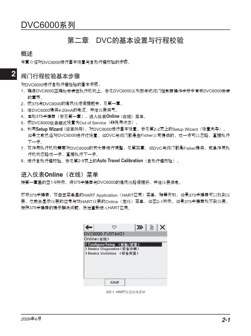
进入仪表Online (在线)菜单按第一章里的图1-9所示,将375手操器与DVC6000的通讯线路连接好,并给仪表供电。
打开375手操器,双击主菜单里的HART Application (HART 应用)菜单,稍等片刻,如果375手操器可以找到仪表,它就会显示仪表的位号与该HART 仪表的Online (在线)菜单,如图2-1所示。
如果375手操器找不到仪表,按照375手操器的提示解决问题,然后重新进入HART 应用。
ᅄ2-1. HARTጥܭᏴሣݩ2ᓖፀǖ当375进入Online (在线)菜单之后有时候会出现如图2-2的屏幕提示,这是因为系统设置或者报警内存等原因,设备提示诸如报警非空或者系统时间无效等。
DVC6000f基本调试步骤
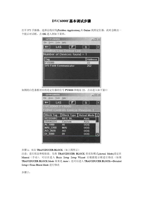
DVC6000f基本调试步骤打开375手操器,选择总线应用(Fieldbus Application),从Online找到定位器,此时会跳出一个提示对话框,点OK进入到如下菜单:如图的白色条框对应的是定位器的位号PY6000和地址22,点击进入如下窗口步骤1:双击TRANSDUCER BLOCK(如上图所示)注意:进行组态和校验前,先将TRANSDUCER BLOCK的实际模式(Actual Mode)设定在Manual(手动)。
可以在进入Basic Setup--Setup Wizard后根据提示框进行修改(如果TRANSDUCER BLOCK Mode原来是Auto),也可以进入TRANSDUCER BLOCK—Detailed Setup—Trans Block Mode进行修改步骤2:步骤3:双击Basic Setup,然后在出现的对话框中双击Setup Wizard步骤4:对于双作用执行机构,只能选择Travel Control(行程控制),点击NEXT。
但是对于单作用执行机构,推荐选用TVL/PRESS Auto Recv说明:Pressure Control(压力控制)。
定位器将当作一个普通电气转换器用,开环控制,在没有行程反馈的状态下工作TVL/PRESS Auto Recv(行程控制带压力控制,自动恢复)。
当行程传感器失效时,能自动切换成压力控制模式。
而当行程传感器能恢复正常工作时,压力控制会被自动恢复到行程控制。
TVL/PRESS Man Recv(行程控制带压力控制,手动恢复)。
当行程传感器失效时,能自动切换成压力控制模式。
但当行程传感器能恢复正常工作时,仍然留在压力控制模式,需要把控制模式手动修改成Travel Control或TVL/PRESS Auto Recv以后,才能恢复行程控制。
步骤5:选择压力单位(Pressure units),再选NEXT进入下一步选择Other(其他)。
FISHER_DVC6000定位器调试说明
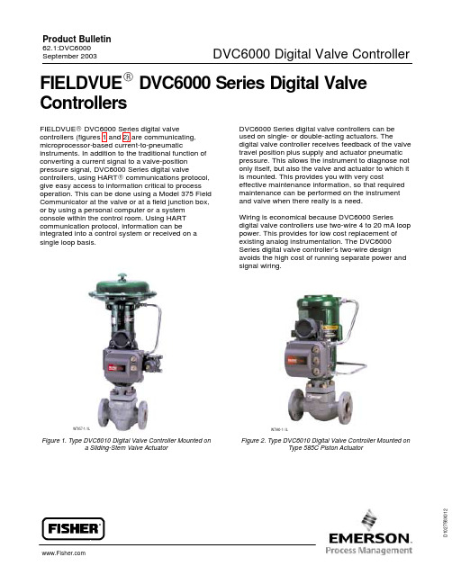
D 102758X 012FIELDVUE R DVC6000 Series Digital ValveControllersFIELDVUE RDVC6000 Series digital valvecontrollers (figures 1 and 2) are communicating,microprocessor-based current-to-pneumaticinstruments. In addition to the traditional function of converting a current signal to a valve-position pressure signal, DVC6000 Series digital valvecontrollers, using HART R communications protocol,give easy access to information critical to process operation. This can be done using a Model 375 Field Communicator at the valve or at a field junction box,or by using a personal computer or a system console within the control room. Using HART communication protocol, information can be integrated into a control system or received on a single loop basis.W7957-1 / ILFigure 1. Type DVC6010 Digital Valve Controller Mounted ona Sliding-Stem Valve Actuator DVC6000 Series digital valve controllers can be used on single- or double-acting actuators. Thedigital valve controller receives feedback of the valve travel position plus supply and actuator pneumatic pressure. This allows the instrument to diagnose not only itself, but also the valve and actuator to which it is mounted. This provides you with very costeffective maintenance information, so that required maintenance can be performed on the instrument and valve when there really is a need.Wiring is economical because DVC6000 Seriesdigital valve controllers use two-wire 4 to 20 mA loop power. This provides for low cost replacement of existing analog instrumentation. The DVC6000Series digital valve controller’s two-wire designavoids the high cost of running separate power and signal wiring.W7960-1 / ILFigure 2. Type DVC6010 Digital Valve Controller Mounted onType 585C Piston Actuator(continued) 2actuator has been tested to 15 meters (50 feet) maximum without performance degradation.2. These terms are defined in ISA Standard S51.1.3. Normal m3/hr--Normal cubic meters per hour at 0_C and 1.01325 bar, absolute; Scfh--Standard cubic feet per hour at 60_F and 14.7 psia.4. Values at 1.4 bar (20 psig) based on a single-acting direct relay; values at5.5 bar (80 psig) based on double-acting relay.5. Not applicable for Type DVC6020 digital valve controllers in long-stroke applications or remote-mounted Type DVC6005 digital valve controllers with long pneumatic tubing lengths.6. Approvals for remote-mounted units are pending.7. The Low Bleed Relay is offered as standard relay for DVC6000 ESD tier, used for On/Off applications.FeaturesD Improved Control—Two-way digital communications give you current valve conditions. You can rely on this real-time information to make sound process management decisions. By analyzing valve dynamics through AMS ValveLink Software , you can identify control areas needing improvement and maintain a high level of system performance. D Environmental Protection—You can avoid additional field wiring by connecting a leak detector or limit switch to the auxiliary terminals in theDVC6000 Series digital valve controller. In this way, the instrument will issue an alert if limits are exceeded.34D Enhanced Safety—You can check instrumentand valve operation and keep the process running smoothly and safely from a remote location. Access is possible at a field junction box, marshalling panel, or within the safety of the control room using either a 375 Field Communicator, a notebook PC, or a system workstation. Your exposure to hazardous environments is minimized and you can avoid having to access hard-to-reach valve locations.D Hardware Savings—DVC6000 Series digital valve controllers, when used in an integrated system, allow you to realize significant hardware and installation cost savings by replacing other devices in the process loop, such as positioners and limit switches, with a FIELDVUE digital valve controller.D Built to Survive—Field-tough DVC6000 Series digital valve controllers have fully encapsulated printed wiring boards that resist the effects of vibration, temperature, and corrosive atmospheres.A separate weather-tight field wiring terminal box isolates field-wiring connections from other areas of the instrument.D Increased Uptime—With the self-diagnostic capability of DVC6000 Series digital valve controllers, you can answer questions about a valve’s performance, without pulling the valve from the line. You can run diagnostics (I/P and relay integrity, travel deviation, and on-line friction and deadband analysis and trending) while the valve is in service and operating. You can also compare the present valve/actuator signature (bench set, seat load, friction, etc.) against previously stored signatures to discover performance changes, before they cause process control problems.D Faster Commissioning—The two-way communication capability allows you to quickly commission loops by remotely identifying each instrument, verifying its calibration, reviewing stored maintenance notes, and more.D Easy Maintenance—DVC6000 Series digital valve controllers are modular in design. The single master module can be removed from the instrument housing without disconnecting the field wiring, pneumatic connections or stem linkages. This module contains the critical sub-modules so component removal is quick and simple.DiagnosticsDVC6000 Series digital valve controllers are packed with user-configurable alerts and alarms. When integrated with a HART communication-based system, these flags provide real-time notification of current and potential valve and instrument problems. With AMS ValveLink R Software, tests can be performed to identify problems with the entire control valve assembly. Diagnostic capabilities available are Performance Diagnostics (PD) and Advanced Diagnostics (AD).Performance DiagnosticsPerformance Diagnostics enables the use of diagnostics while the valve is in service and operating.D Red/Yellow/Green Condition Indicator(see figure 3)D I/P and Relay Integrity DiagnosticD Travel Deviation DiagnosticD1-Button DiagnosticD On-Line Friction and Deadband Analysis(see figure 4)D Friction and Deadband TrendingWhile all diagnostics can be run while the valve is inline, only the Performance Diagnostics can be performed while the valve is in service and operating.5ERROR(RED)NO CONDITIONS HAVE BEEN DETECTED(GREEN)Figure 3. Red/Yellow/Green Condition Indicators, Shown in AMS ValveLink SoftwareFigure 4. Valve Friction and Deadband AnalysisAdvanced DiagnosticsAdvanced Diagnostics include the following dynamic scan tests:D Valve Signature (see figure 6)D Dynamic Error Band D Instrument Drive SignalThese diagnostic scans vary the positioner set point at a controlled rate and plot valve operation to determine valve dynamic performance. The valve signature test allows you to determine thevalve/actuator friction, bench set, spring rate, and seat load. The Dynamic Error Band test is a combination of hysteresis and deadband plus “slewing.” Hysteresis and deadband are static measurements. However, because the valve is moving, a dynamic error, or “slewing” error is introduced.Dynamic scan tests give a better indication of how the valve will operate under process conditions which are dynamic, not static.The Step Response Test checks the valveassemblies response to a changing input signal. and plots travel versus time. The end results of this test allow you to evaluate the dynamic performance of the valve. The Performance Step Test (25pre-configured points) provides a standardized step test with which to evaluate your valve performance.It utilizes small, medium and large changes.Advanced Diagnostics are performed with AMS ValveLink Software . The valve must be out ofservice for Advanced Diagnostics to be performed.6W8082 / ILHART MULTIPLEXERControl System I/O4-20 mA+HARTFigure 5. Integrate Information from the Digital Valve Controller into a Non-HART Compatible Control System With AMS ValveLinkSoftware’s Modbus InterfaceW7468/ILFigure 6. The Valve Signature DisplayIntegrationD Non-HART Systems—Because DVC6000Series digital valve controllers operate with atraditional 4 to 20 mA control signal, they directlyreplace older analog instruments.Microprocessor-based electronics provide improvedperformance along with repeatable and reliableconfiguration and calibration.D Modbus with AMS ValveLink Software andHART Multiplexers—HART communication allowsyou to extract more value from DVC6000 Seriesdigital valve controllers beyond their inherentimproved performance. When integrated into amultiplexer network and using AMS ValveLinkSoftware, the device and valve information isreal-time. From the safety of a control room, multipleinstruments can be monitored for alerts and alarms.Additionally, tasks such as configuration, calibrationand diagnostic testing do not require special trips tothe field. AMS ValveLink Software can communicatevia Modbus to the distributed control system (DCS)to provide critical information such as valve travelalerts and alarms (figure 5).D Integrated Control System—A control systemwith HART communication capabilities has the abilityto directly gather information from DVC6000 Seriesdigital valve controllers. Information such as valvetravel, alerts and alarms can be seamlesslyaccessed to provide a view into the field device fromthe safety of the control room.71200 Hz “1”2200 Hz “0”AVERAGE CURRENT CHANGE DURING COMMUNICATION = 0A6174/ILFigure 7. HART rFrequency Shift Keying TechniqueFigure 8. Perform Configuration and Calibration at the Valve or Anywhere on the 4 to 20 mA Loop with the Model 375Field CommunicatorCommunicationHART Protocol OverviewThe HART (Highway Addressable Remote Transducer) protocol gives field devices thecapability of communicating instrument and process data digitally. This digital communication occurs over the same two-wire loop that provides the 4 to 20 mA process control signal, without disrupting the process signal (figure 7). In this way, the analog process signal, with its faster response, can be used for control. At the same time, the HART digital communication gives access to calibration,configuration, diagnostic, maintenance, andadditional process data. The protocol provides total system integration via a host device.Model 375 Field CommunicatorYou can perform configuration and calibration at the valve or anywhere on the two-wire loop via a Model 375 Field Communicator (figure 8). Powerful tools such as the Setup Wizard and Auto TravelCalibration automate the tasks of commissioning DVC6000 Series digital valve controllers. Theseautomation tools not only save time, but also provide accurate and repeatable results.AMS ValveLink SoftwareAMS ValveLink Software is a Windows-based software package that allows easy access to the information available from DVC6000 Series digital valve controllers.Using AMS ValveLink Software, you can monitor the performance characteristics of the valve and obtain vital information without having to pull the valve from the line. I/P and Relay Integrity and Travel Deviation Diagnostics, as well as On-Line Friction andDeadband Analysis and Trending can be run while the valve is in service and operating. ValveSignature, Dynamic Error Band, and Step Response are displayed in an intuitive user-friendlyenvironment that allows easy interpretation of data.Diagnostic graphs can be superimposed over those previously stored to view areas of valve degradation.This allows plant personnel to concentrate efforts on equipment that needs repair, avoiding unnecessary maintenance. This diagnostic capability is readily accessible and available to you either in the control room or on the plant floor. In addition to the diagnostic features, AMS ValveLink Softwarecontains an Audit Trail, Batch Runner for automating repetitive tasks, and Trending to view valve performance.AMS ValveLink Software provides integration into AMS and DeltaV, with HART and Fieldbus communications.TRAVEL SENSORTERMINAL BOXTERMINAL BOX COVERPRINTED WIRING BOARD ASSEMBLYI/P CONVERTERPNEUMATIC RELAYGAUGESCOVERW8083-1 / ILFigure 9. DVC6000 Series Digital Valve Controller Assembly (valve-mounted instrument)Principle of OperationDVC6000 Series instruments (figures 9 and 10) receive a set point and position the valve where it needs to be.D The input signal provides electrical power and the set point simultaneously. It is routed into the terminal box through a twisted pair of wires.D The input signal is then directed to the printed wiring board assembly where the microprocessor runs a digital control algorithm resulting in a drive signal to the I/P converter.D The I/P converter assembly is connected to supply pressure and converts the drive signal into a pressure output signal.D The I/P output is sent to the pneumatic relay assembly. The relay is also connected to supply pressure and amplifies the small pneumatic signal from the I/P converter into a single larger pneumatic output signal used by a single-acting actuator. For double-acting actuators, the relay accepts the pneumatic signal from the I/P converter and provides two pneumatic output signals.D The change in relay output pressure to the actuator causes the valve to move.D Valve position is sensed through the feedback linkage by the instrument’s travel sensor. The travel sensor is electrically connected to the printed wiring board to provide a travel feedback signal used in the control algorithm.The valve continues to move until the correct position is attained.8E0408 / ILFigure 10. DVC6000 Series Digital Valve Controller Block DiagramInstallationThe Type DVC6010 digital valve controller is designed for yoke mounting to sliding stem actuators. Type DVC6020 digital valve controllers are designed for mounting to rotary actuators or long stroke sliding stem actuators (over 4-inches travel). Type DVC6030 digital valve controllers are designed for mounting on virtually any quarter-turn actuator. Dimensions for valve-mounted instruments are shown in figures 11, 12, and 13. Dimensions for remote-mounted instruments are shown in figures 14 and 15.The Type DVC6005 digital valve controller base unit may be remote mounted on 2-inch pipestand or wall. The remote-mounted Type DVC6005 base unit connects to the Type DVC6015, DVC6025, orDVC6035 feedback unit mounted on the actuator. Feedback wiring and pneumatic tubing to the control valve assembly must be connected in the field.9102 MOUNTING HOLES 8.6 (0.34)1/4-18 NPTOUTPUT CONN B28.6(1.13)122.8(4.84)144.5(5.69)210.7(8.29)148.7(5.85)ACTUATOR CENTERLINE1/4-18 NPTOUTPUT CONN PLUGGED1/2-14 NPTCONDUIT CONN BOTH SIDES 1/4-18 NPTOUTPUT CONN A 1/4-18 NPT VENT CONNTYPE 67CFR 1/4-18 NPTSUPPLY CONNFigure 11. Dimensions for Type DVC6010 Digital Valve Controller with Integrally Mounted Filter Regulator4 MOUNTING HOLES j 95.3(3.75)158.1(6.23)156.3(6.16)1/2-14 NPTCONDUIT CONN BOTH SIDES 1/4-18 NPTOUTPUT CONN A TYPE 67CFR 1/4-18 NPTSUPPLY CONN19B3557-A E0406 / ILmm(INCH)Figure 12. Dimensions for Type DVC6020 Digital Valve Controller with Integrally Mounted Filter Regulator19B3558-A E0407 / ILmm (INCH)Figure 13. Dimensions for Type DVC6030 Digital Valve Controller with Integrally Mounted Filter Regulator11PIPESTAND MOUNTED10C1795-A / DOC10C1796-A / DOC234184mm (INCH)WALL MOUNTED64(2.50)57(2.25)72(2.82)HOLES 0.86 (0.34)Figure 14. Dimensions for Remote-Mounted Instruments--Type DVC6005 Base UnitThe digital valve controllers are 4 to 20 mA loop powered and do not require additional power.Electrical connections are made in the terminal box.All pressure connections on the digital valvecontrollers are 1/4-inch NPT female connections.The digital valve controller outputs are typically connected to the actuator inputs using 3/8-inch diameter tubing. Remote venting is available.Ordering InformationNote: Fisher does not assume responsibility for the selection, use, or maintenance of anyproduct. Responsibility for proper selection, use,and maintenance of any Fisher product remains solely with the purchaser and end user.When ordering, specify:1. Actuator type and size2. Maximum actuator travel or rotation3. Optionsa. Supply pressure regulatorb. Supply and output gaugesc. HART filterd. Stainless steel housing (valve-mounted instruments only)e. Remote mountingTYPE DVC6015 SLIDING STEM ACTUATOR MOUNTINGUP TO 102 mm (4−INCH) TRAVEL TYPE DVC6025 ROTARY AND LONG−STROKE SLIDING STEMACTUATOR MOUNTINGE0867 / IL10C1799-AE0869 / ILTYPE DVC6035 ROTARY ACTUATOR SHAFT MOUNTING10C1798-A E0868 / ILmm (INCH)(4.50)(3.00)38(1.50)HOLES1/4 - 20 UNC46(1.83)46(1.81)67103135120CONDUIT CONNFigure 15. Dimensions for Remote-Mounted Instruments--Feedback UnitsFisherMarshalltown, Iowa 50158 USA Cernay 68700 France Sao Paulo 05424 Brazil Singapore 128461The contents of this publication are presented for informational purposes only, and while every effort has been made to ensure their accuracy,they are not to be construed as warranties or guarantees, express or implied, regarding the products or services described herein or their use or applicability. We reserve the right to modify or improve the designs or specifications of such products at any time without notice.Fisher does not assume responsibility for the selection, use or maintenance of any product. Responsibility for proper selection, use and maintenance of any Fisher product remains solely with the purchaser and end-user.FIELDVUE, ValveLink and Fisher are marks owned by Fisher Controls International LLC, a business of Emerson Process Management. The Emerson logo is a trademark and service mark of Emerson Electric Co. HART is a mark owned by the HART Communications Foundation.All other marks are the property of their respective owners. This product may be covered under one or more of the following patents (5,451,923; 5,434,774; 5,439,021; 5,265,637) or under pending patent applications.Emerson Process Management 。
FISHERDVC6000系列阀门定位器原理和检修
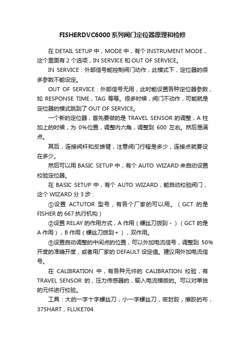
FISHERDVC6000系列阀门定位器原理和检修在DETAIL SETUP中,MODE中,有个INSTRUMENT MODE,这个里面有2个选项,IN SERVICE 和OUT OF SERVICE。
IN SERVICE:外部信号能控制阀门动作,此模式下,定位器的很多参数不能设定。
OUT OF SERVICE:外部信号无用,此时能设置各种定位器参数,如RESPONSE TIME,TAG等等。
很多时候,阀门不动作,可能就是定位器的模式跳到了OUT OF SERVICE。
一个新的定位器,首先要做的是TRAVEL SENSOR的调整,A柱加上的时候,为0%位置,调整内六角,调整到600左右。
然后是满点。
其后,连接阀杆和反馈臂,注意阀门行程是多少,连接点就要设在多少。
然后可以用BASIC SETUP中,有个AUTO WIZARD来自动设置校验定位器。
在BASIC SETUP中,有个AUTO WIZARD,能自动校验阀门,这个WIZARD分3步:①设置ACTUTOR型号,有各个厂家的可以用。
(GCT的是FISHER的667执行机构)②设置RELAY的作用方式,A作用(螺丝刀拨到-)(GCT的是A作用),B作用(螺丝刀拨到+),双作用。
③设置自动调整的中间点的位置,可以外加电流信号,调整到50%开度的准确开度,或者用厂家的DEFAULT设定值。
建议用外加电流信号。
在CALIBRATION中,有各种元件的CALIBRATION校验,有TRAVEL SENSOR的,压力传感器的,输入电流模版的。
可以对单独的元件进行校验。
工具:大的一字十字螺丝刀,小一字螺丝刀,密封胶,擦胶的布,375HART,FLUKE704呆扳手:7/8 11/16 1/2 7/16 1/4 5/16 套筒扳手英制一套。
白布一大块手电。
475调试DVC6200定位器

ROSEMOUNT 475现场通讯器调试FISHER DVC6200定位器步骤说明版权所有:大连保税区路迈顺国际贸易有限公司一、初始引导设置调试步骤进入界面,选择HART选择Online如有报警信号,选择YESOnline下拉菜单选择Configure(组态)选择Guided Setup(引导设置)菜单选择Device Setup警告菜单选择Out of Service压力单位选择可任意,选择Psi放大器类型,选择A or C用于单作用和双作用放大器,B为反作用定位器。
选择Travel Control行程控制执行器制造厂商选择Fisher(如果是国产执行机构,可根据具体参数对应Fisher执行机构来选)执行机构的型号根据执行机构铭牌来选择。
执行机构尺寸型号选择同样根据执行机构铭牌进行输入阀门气开气关,可根据条件选择开始驱动阀门,设置行程传感器动作,选择YES定位器自动捕捉行程传感器动作。
等待下图界面弹出根据现场执行机构安装的附件,选择是否含有流量放大器和快排阀,有选择Yes,没有选择no。
发送设备设置数据给仪表,按Enter等待发送,发送完成后如下图界面使用工厂默认设置选择YES发送工厂默认数据中,等待完成后出现下图界面设备设置完成选OK完成阀门设置,需要运行阀门自动行程校验,选择OK选择Yes阀门自动校验中,分别捕捉高、低驱动点调整输出偏离等待自动校验中阀门校检完成,点OK选择OK二、直接校验行程(引导设置已经完成,可直接进行行程校验)进入界面,选择HART选择Online如有报警信号,选择YES后enterOnline下拉菜单选择Configure选择Calibration菜单选择Auto Calibration选择非投用Out of Service选择CONTINUE 后,选择travel control阀门自动校验无须操作,只需等待直到下图界面自动校验完成OK 键确认选择OK修改为In Service 状态,校检完成。
DVC6000 调试基本步骤

DVC6010 调试基本步骤:准备工作:定位器调试前必须已将机务阀杆与执行器输出推杆正确连接,并已将定位器反馈臂与执行器推杆上反馈用连接臂正确连接。
同时气源压力必须调整到正确值。
开度反馈如用T ri-Loop,必须先激活并已正确设置!机务阀杆与执行器输出推杆连接:因执行器为单作用下缸进气的气开式阀门(开时定位器反馈臂逆时针旋转向上),连接前要求机务将阀门门杆完全向下压倒底,保证阀门处于完全关闭状态。
直接向执行器气缸输入铭牌“BENCH SET:14 —30”中下限压力并适当放大1~2psi,然后将执行器输出推杆与机务阀杆连接。
连接后的理想状态是当气缸输入压力大于“BENCH SET:14 —30”中下限压力时能较快地开始开启,当气缸输入压力达“BENCH SET:14 —30”上限时能够全开。
定位器反馈臂连接:断开至执行器气缸气源,阀门处于全关状态,确认执行器输出推杆上反馈用连接臂已正确用螺丝固定,从定位器内部旋出连接用定位销,将定位销穿过定位器反馈臂上标记为“A”的孔(如是气关式则为“B”孔)并插入定位器壳体上的定位孔,使定位器反馈臂固定不动,根据铭牌“TRA VEL:3/4(inch)”中的执行器行程值,上下滑动调整调整臂与推杆上连接臂的位置,使调整臂在定位器反馈臂滑槽内对准有相应行程标注的数字刻度处,然后拧紧调整臂与推杆上连接臂的连接固定螺母。
注意,调整臂是将定位器反馈臂与执行器推杆上反馈连接臂的连接过渡。
气源压力调整:调整减压阀使气源压力闭执行机构要求的最大值(参考BENCH SET 上限)高0.3bar(5psi),注意此压力必须能使锁气器完全顶开,离开锁气状态。
按检修规程要求锁气器闭锁压力的调整一般不得低于0.3MPa。
Tri-Loop激活并设置:先通讯器连接DVC6000,ONLINE Setup&Diag Detailed Setup Mode Burst Burst Enable,设置成激活状态。
Fisher DVC6000系列智能定位器
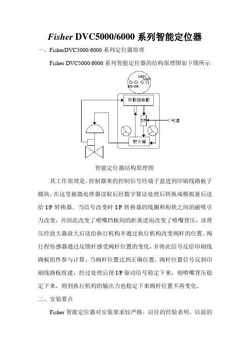
Fisher DVC5000/6000系列智能定位器一、FisherDVC5000/6000系列定位器原理Fisher DVC5000/6000系列智能定位器的结构原理图如下图所示智能定位器结构原理图其工作原理是,控制器来的控制信号经端子盒进到印刷线路板子模块,在这里被微处理器读取后经数字算法处理后转换成模拟量后送给I/P转换器。
当信号改变时I/P转换器的线圈和衔铁之间的磁吸引力改变,并因此改变了喷嘴挡板间的距离进而改变了喷嘴背压,该背压经放大器放大后送给执行机构并通过执行机构改变阀杆的位置。
阀行程传感器通过反馈杆感受阀杆位置的变化,并将此信号反给印刷线路板组件参与计算。
当阀杆位置达到正确位置,阀杆位置信号反到印刷线路板组建,经过处理后使I/P驱动信号稳定下来,则喷嘴背压稳定下来,则到执行机构的输出力也稳定下来阀杆位置不再变化。
二、安装要点Fisher智能定位器对安装要求较严格,以往的经验表明,以前的几次阀门校验出错都是因为安装错误造成的。
Fisher智能定位器的反馈杆如图所示其上有A、B两个孔来确定连接位置。
当阀门为风开阀时,定位销钉穿过A孔插入定位器表体上的固定孔,当阀门为风关阀时,定位销钉穿过B孔插入定位器表体上的固定孔来确定连接位置。
然后将十字架的连接杆放入反馈杆的槽内,其所放位置与该阀的行程相对应。
三、275型HART通讯器简介HART通讯器各部分功能如图所示:校验时将HART编程器的引出线接到定位器的LOOP+与LOOP-端子,接线时不分极性。
四、初始设置和校准4.1为了对定位器进行设置和校准必须用HART编程器将仪表模式必须设成“Out of service”并且将保护设为“None”。
如果仪表模式不在“Out of service”模式下时,则按以下步骤将仪表模式设为“Out of service”。
1、将HART编程器接好并打开电源。
2、按HART编程器上的热键并选择仪表模式或从主菜单→详细设置→模式(Mode)→仪表模式(Instrument Mode)来选择仪表模式。
475手操器中文使用手册
2简介3爆炸可能会导致严重伤害或死亡:在有爆炸危险的环境中使用时,必须遵守相关的本地、国家和国际标准、规范和规程。
请查阅《475型现场通讯器用户手册》中的“参考信息”和“产品认证”部分,以了解有关安全使用的限制规定。
触电可能会导致严重伤害或死亡。
此设备符合 FCC 规范的第 15 部分。
设备操作应符合以下两个条件:(1) 本设备可能不会产生有害干扰,以及 (2) 本设备必须接受任何接收到的干扰,包括可能会导致非预定操作的干扰。
©2009 艾默生过程管理。
保留所有权利。
HART 为 HART 通信基金会的注册商标。
F OUNDATION为现场总线基金会的商标。
IrDA 为红外数据协会的注册商标。
Bluetooth 为 Bluetooth SIG, Inc. 的注册商标。
AMS Suite 为艾默生电气公司的注册商标。
艾默生标志为艾默生电气公司的商标和服务标志。
所有其他商用标志的所有权归其各自的所有者。
简介《475型现场通讯器使用入门指南》提供了 475型现场通讯器的基本操作指南、注意事项和设置信息。
它不包括有关配置、诊断、维护、保养、故障排除或本质安全 (IS) 安装的详细说。
有关更多说明,请参阅资源 CD 里的《475型现场通讯器用户手册》或访问。
475型现场通讯器支持 HART 和 F OUNDATION现场总线设备,使您可以进行现场配置或排除故障。
电子设备描述语言 (EDDL) 技术使得 475型现场通讯器能与大量不同生产商的设备进行通讯。
4475 型现场通讯器概述475 型现场通讯器概述便携式 475 型现场通讯器包括一个彩色 LCD 触摸屏、一块锂离子电池(电源模块)、一个 SH3 处理器、存储组件以及集成通讯与测量电路。
当使用 475 型现场通讯器与设备进行通讯时,请遵守当地适用的所有标准和程序。
不遵守这些标准和程序可能会导致设备损坏和/或人身伤害。
请理解并遵守本手册中的各项内容。
475手操器使用方法与故障维修

475手操器使用方法与故障维修小编在朋友们的帮助下整理了部分475手操器的使用方法和故障维修经验资料,及常用菜单的中英文对照总结,希望能帮助仪表人掌握并使用好475手操器。
手操器是什么?其实我们常说的手操器应该叫做现场通讯器(field communicator),是为了组态调试现场仪表使用的。
现场仪表受限于尺寸往往显示信息和按键有限,使用通讯协议的手操器可以显示更详细的信息,更方便调试,也提供了在机柜间而不用去现场调试仪表的选择,让仪表工作人员更便利更安全。
HART475手操器支持超过200个供应商的1,500 多种HART 和Ff现场总线设备, 能完美地与您的设备协同工作。
通过便利升级选项, 可以获得最新的HART和Ff现场总线设备描述文件(DD)。
475 现场通讯器, 确保通过单一的本安手操器, 完成对HART和现场总线仪表的通用支持。
手操器产品手操产品品牌多样,常用的国外产品有:Rosemount/罗斯蒙特最常用的型号罗斯蒙特手操器475HP1ENA9GM9(基本型)罗斯蒙特手操器475HP1ENAUGMT(三年升级)罗斯蒙特手操器475HP1EKL9GM9T(防爆)罗斯蒙特手操器475HP1EKLUGM9T(防爆+三年升级)罗斯蒙特手操器475FP1EKLUGMT(HART+FF协议)YOKOGAWA/横河BT200系列HONEYWELL/霍尼韦尔 MCT202手操器SIEMENS/西门子HART 475手操器部分国内产品有:西安欧迪475手操器西安能特475手操器北京华控475hart手操器如何使用475手操怎样连接?一般手操器的两个表笔(或者是钩子和夹子)要加到仪表的电流输出的两个端子上(对于二线制仪表当然就是电源端子)。
两个表笔不分正负。
如何调试仪表?首先,请阅读仪表的使用说明书,只要你的仪表支持hart协议,里面就会有Online之后的菜单结构以及每个调试项的详细解释。
往往需要调节的包括:位号检查与设置(Tag),测量源的选择,测量单位,仪表的输出方式,输出定标(对于电流输出就是上下限,URV和LRV),滤波与信号处理(最常见的是damp,阻尼时间),实际测试,与DCS回路测试等等。
475手操器与DVC6000调试黄波解析

费希尔控制阀校验
Max Supply Press(psi)(最大气源压力) 30 DEL ABORT ENTER
Actuator Manufcturer(Fisher controls)执行机构的制造商 Fisher controls Baumann Gulde ATI Masonelian Neles-jannesbury Valtek ENTER
费希尔控制阀校验
• 校验:
Online 1 Setup&Diag(设置和诊断) 2 Analog In (模拟输入) 3 Travel(行程) 4 Valve SP(阀门设定点) 5 Drive Sgl(驱动信号) 6 Pressures(压力) 7 Instrument Status (仪表状态) SAVE
费希尔控制阀校验
REMINDER: Instrument must be returned to in SERVICE for output to track input 输出跟踪输入仪表模式必须返回投用状态
OK Basic Setup 1 Auto Setup (自动设置) 2 Manual Setup(手动设置) SAVE HOME
费希尔控制阀校验
Auto Setup 1 Setup Winzard (设置向导 ) 2 Relag Adjust (气动放大器调整 ) 3 Auto Calib Travel (自动校验行程) 4 Stabilize/Optimize (稳定/优化) HELP SAVE HOME Pressure Units(psi) (压力单位) psi bar kpa ABORT ENTER
确定行程位置:
行程
1. 调整臂销钉 必须置于补 偿弹簧之上 2. 销钉位置对 应阀门行程
DVC6000 调试基本步骤
DVC6010 调试基本步骤:准备工作:定位器调试前必须已将机务阀杆与执行器输出推杆正确连接,并已将定位器反馈臂与执行器推杆上反馈用连接臂正确连接。
同时气源压力必须调整到正确值。
开度反馈如用T ri-Loop,必须先激活并已正确设置!机务阀杆与执行器输出推杆连接:因执行器为单作用下缸进气的气开式阀门(开时定位器反馈臂逆时针旋转向上),连接前要求机务将阀门门杆完全向下压倒底,保证阀门处于完全关闭状态。
直接向执行器气缸输入铭牌“BENCH SET:14 —30”中下限压力并适当放大1~2psi,然后将执行器输出推杆与机务阀杆连接。
连接后的理想状态是当气缸输入压力大于“BENCH SET:14 —30”中下限压力时能较快地开始开启,当气缸输入压力达“BENCH SET:14 —30”上限时能够全开。
定位器反馈臂连接:断开至执行器气缸气源,阀门处于全关状态,确认执行器输出推杆上反馈用连接臂已正确用螺丝固定,从定位器内部旋出连接用定位销,将定位销穿过定位器反馈臂上标记为“A”的孔(如是气关式则为“B”孔)并插入定位器壳体上的定位孔,使定位器反馈臂固定不动,根据铭牌“TRA VEL:3/4(inch)”中的执行器行程值,上下滑动调整调整臂与推杆上连接臂的位置,使调整臂在定位器反馈臂滑槽内对准有相应行程标注的数字刻度处,然后拧紧调整臂与推杆上连接臂的连接固定螺母。
注意,调整臂是将定位器反馈臂与执行器推杆上反馈连接臂的连接过渡。
气源压力调整:调整减压阀使气源压力闭执行机构要求的最大值(参考BENCH SET 上限)高0.3bar(5psi),注意此压力必须能使锁气器完全顶开,离开锁气状态。
按检修规程要求锁气器闭锁压力的调整一般不得低于0.3MPa。
Tri-Loop激活并设置:先通讯器连接DVC6000,ONLINE Setup&Diag Detailed Setup Mode Burst Burst Enable,设置成激活状态。
费舍尔DVC6000调试方法
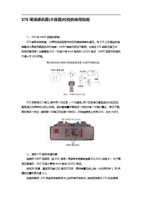
375现场通讯器(手操器)校验的使用指南一、375与HART回路的联接375能够与控制室、仪表现场或回路中的任何接线端接头通讯。
将375以及适当的连接器与仪表或负载阻抗并行连接,HART接线对极性不敏感。
为保证375能够正常工作,现场设备终端(这里是指DVC)处至少有4mA电流和12VDC电压,HART回路中的阻抗不得小于250欧姆。
375顶部有三个端口。
其中两个为红色,一个为黑色。
两个红色端口是各自协议的正极。
黑色端口为两种协议的公共端。
保护盖装置可确保任一时刻只有一对端口露出,参见下图。
同时有多个标记,指明哪一对端口对应哪一种协议,对防喘振阀上所用DVC,均为HART。
二、启动375型现场通讯器连接好HART回路后,给DVC信号(用信号发送器或者是PLC/DCS供电卡),为了确保正常通讯,DVC处至少要有4mA电流12VDC电压。
按住开/关键,直至多功能LED指示灯闪烁,表明装置已经上电(大约两秒钟)。
开/关键的位置可参见图2-2。
在启动期间,375将自动安装系统卡上的所有升级软件。
完成后将显示375的主菜单,您可以从中选择:1、HART Application(启动HART应用)2、FOUNDATION Fieldbus Application(启动基金会现场总线应用程序)3、Setting(组态/查看设置)4、Listen For PC(进入PC控制方式)5、ScratchPad(启动ScratchPad应用程序)三、关机当应用程序打开时,开/关键被禁用。
使用开/关键之前,您必须返回到375的主菜单。
如果要关闭375,可按住开/关键直至其显示关闭(大约三秒钟)。
四、设定和校验对于防喘振阀所配DVC,选择HART Application(启动HART应用)。
如果375已联接在DVC上,并已给DVC信号,这时375将直接进入Online(在线)菜单,否则将进入Field Communicator(现场通讯器)菜单:1、Offline(离线)2、Online(在线)3、Utility在Field Communicator(现场通讯器)菜单中选择Online(在线)后,将进入Online(在线)菜单:1、Setup &Diag(设置和和诊断)2、Analog in(模拟输入)3、Travel(行程)4、Valve SP(阀门设定点)5、Drive Sgl(驱动信号)6、Pressure(压力)7、Instrument Status(仪表状态)选择Setup &Diag(设置和和诊断)进入该菜单:1、Basic Setup(基本设置)2、Detailed Setup(详细设置)3、Display(显示)4、Calibrate(校验)5、Stroke Valve(驱动阀门)对于一台没有校验过的或是从另一台阀门上拆下装到这台阀门上的DVC,选择Basic Setup(基本设置):1、Auto Setup(自动设置)2、Manual Setup(手动设置)对375不太熟的用户可选择Auto Setup(自动设置):1、Setup Wizard(设置向导)2、Relay Adjust(放大器调整)3、Auto Calib Travel(自动校验行程)4、Stabilize/Optimize(稳定/优化)5、Performance Tuner(特性整定)6、注:为了设定和校验仪表,Instrument Mode(仪表模式)必须置于Out Of Service (非投用状态)。
DVC6000系列定位器安装调校步骤
dvc6000系列定位器安装在直行程执行机构上的调教步骤1.参考调节阀铭牌信息了解以下参数的意义;a.TYPE——(执行机构类型)b. SIZE——(执行机构尺寸)c. TRA VEL——(执行机构行程)d. OPER RANGE——(压力操作范围)2.安装定位器(依照厂家图纸)a.打开定位器保护罩盖,在主模块靠近I/P转换器的地方取下左上角的“定位销”b.如果最大行程大于4英寸要采用“加长型反馈臂”和“调整臂”c.对于气开式执行机构(667),要把定位销插入标记为“A”的孔里d.对于气关式执行机构(657),要把定位销插入标记为“B”的孔里e.安装调整臂使其滑动,直到它的销子对准相应的“阀门行程标记”,然后旋紧带垫片的六角螺母。
f.取走定位销,把它放回主模块靠近I/P转换器的地方。
3.组态定位器参数a.利用手操器取消“组态保护”,设定为“NONE”,可以进行以下操作;当手操器显示“跳线”时,用一根短接线“短接AUX(辅助接线端子)”,按“OK”确认。
再断开,在按ok,手操器提示保护解除。
b.将“instrument mode 仪表模式”改为“非投用状态”,在校验和设定时必须改为“OUTOF SERVICE”c.进入“auto setup 自动设置”利用“setup wizard 设置诀窍”修改以下参数输入压力单位、执行机构设置、安装类型、等等。
d.也可以进入手动设置阀门的各种参数,详细见275、375手操器菜单。
4.校验(自动校验1-4-2)a.如果定位器不能被校验,可以通过“restore calibration”“1-4-6”恢复到出厂设定。
b.如果反馈杆是“sstem-standard 滑杆-标准”时需要调整交叉点,其他两种方式“旋转、滚轮”不需要。
调整好交叉点后便可进入“AUTO CALIB Traver”,手操器会提示你自动校验行程。
c.调整交叉点可以选择“手动、前次值、缺省值”,如果选择“手动”则会提示你选择调整源是“模拟”或“数字”。
DVC6000系列定位器475手操器调试 ppt课件

11. 选择Actuator Model(执行机构型号)。如果执
行机构型号未出现在列表中,选Other(其它),点 击ENTER(回车)。
12. 选择Actuator Size(执行机构尺寸)的大 小。点击ENTER(回车)
10.如果不是费希尔执行机her;则进入下面菜单, 根据执行机构类型选择
12. 选择阀门类型,选直行程
13. Tvl Tuning Set(行程整定参数组)— 选择合适的整定参数 组。如果不知道哪一组整定参数最合适时,请暂时先用一组
较慢的整定参数如C或D,然后进行校验
14. 零信号位置
15. 选择传感器方向,选yes
选择第二项,进入选择离线,退到手动 设置菜单
退到手动设置菜单,选择第六项,输出
进入Outputs项,进入第四项,进入选择相反 项,点击发送SEND
进入手动与保护项,将设备改成在线状 态
故障
1. 检查执行机构气管连接是否有漏气;
2. 检查定位器与反馈磁条或旋转型的凸轮 是否安装正确;
2020/12/27
DVC6000
系列定位器校准
1. 475手操器连接到定位器指令端子上,进入Online菜单; 选择第二项Configure 菜单
精品资料
• 你怎么称呼老师? • 如果老师最后没有总结一节课的重点的难点,你
是否会认为老师的教学方法需要改进? • 你所经历的课堂,是讲座式还是讨论式? • 教师的教鞭 • “不怕太阳晒,也不怕那风雨狂,只怕先生骂我
36
3.填料压盖太紧或阀体
2020/12/27
37
Thank you
16. 选择NO,按ENTER
17. 设备设置发送到仪表,选send
费希尔DVC6000系列定位器的调校
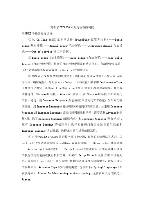
费希尔DVC6000系列定位器的调校用HART手操器进行调校:①从On line(在线)菜单里选择Setup&Diag(设置和诊断)——Basic setup(基本设置)——Manual setup(手动设置)——Instrument Manual(仪表模式)——Out of service(非工作状态)。
②Basic setup (基本设置)——Auto setup (自动设置)——Auto Calib Travel(自动校验行程)剩余的自动校验步骤是自动进行的。
自动校验完成后,HART会提示您将仪表设置到In Service(投用状态)。
③如果在完成基本设置和校验之后,阀门还是振荡或过调(不稳定),或响应不灵(响应缓慢),您可以Auto Setup (自动设置)菜单中Performance Tune (性能优化整定)或Stabilize/Optimize(稳定/优化)改善调试结果;其中有两种选择:Standard(标准)、Advanced(高级)。
在Standard(标准)中如果阀门工作不稳定,用Decrease Response(削弱响应)来使阀门工作稳定;如果阀门响应缓慢,用Increase Response(增加响应)来使阀门响应灵敏。
如果用Decrease Response或Increase Response后阀门超调还是很严重,需要选择Advanced(高级)项,除了Decrease Response(削弱响应) 和Increase Response(增加响应),还有Decrease Damping(降低阻尼) 选择允许阀门有更多过调的阻尼值和Increase Damping(增加阻尼) 选择减少阀门过调的阻尼值。
④对于FISHER DVC6000系列数字阀门定位器,典型的安装调试方式为:从On line(在线)菜单里选择Setup&Diag(设置和诊断)——Basic setup(基本设置) ——Auto setup (自动设置) ——Setup Wizard(设置诀窍),首先是选择所调试的执行机构制造商或执行机构型号,如果在Setup Wizard(设置诀窍)中没有列出,就选择Other(其它)来作为执行机构制造商或执行机构型号,被提示设定的参数如下:Actuator Type(执行机构类型)选项如下:Spring&Diaphragm(弹簧膜片式)、Piston Double-acting without spring(无弹簧双作用气缸式)、PistonSingle-acting with spring(带弹簧单作用气缸式)、Piston Double-acting with spring(带弹簧双作用气缸式)。
475(HART)手操器使用教程

475(HART)手操器使用教程HART手操器:HART(Highway Addressable Remote Transducer),可寻址远程传感器高速通道的开放通信协议,是一种用于现场智能仪表和控制室设备之间的通信协议。
使用它几乎可用来完成所有的现场仪表检修调试工作,包括故障诊断,日常检修,开车调试,校准等。
你是怎样用HART475配置压力变送器的?先看看小7总结的吧:1.开机,将手操器与仪表连接,选择HART2.通讯成功以后,选择Online(在线)当出现以下文字时,不要慌张,点YES就行3.具体操作,以川仪(EJA)为例。
改量程改位号、改单位回路测试(打点)调零点PS:在更改完数据后要选“SEND”发送给变送器HART475图形图像都说明了啥现场通讯器屏幕布局常用按钮使用下列按钮,可修改窗口上曲线图和图表的(以艾默生HART475为例)平移,触击按钮,选择图表或曲线图中的一点,拖动此点在窗口中反复地移动。
区域缩放,触击按钮,然后触击并拖动图表中的一点来创建放大的方框。
当您从窗口释放触笔后,图表将放大并适应此区域。
此控件仅可用于条形图表和曲线图。
放大,触击此按钮,从图表中心以固定比率放大。
再次触击,重复此操作。
缩小,触击此按钮,从图表中心以固定比率缩小。
再次触击,重复此操作。
重置,触击按钮,将图表或曲线图返回至原始主屏幕,取消您执行的任何平移或缩放操作。
下拉列表,触击此菜单,在不同的变量中选择,在图表上或曲线图的不同波形中高亮显示。
图形选项图像图像是设备的全屏幕照片。
图像可包含标识和多种图形,如容器。
要查看图像,选择菜单中的图像或绘图标签。
显示全屏幕图像。
要返回菜单视图,按任何键或触击触摸屏。
一些图像具有链接,可以运行方法或查看附加菜单。
如果图像具有链接,将在菜单中的图像或绘图标记旁出现箭头。
当打开图像后,使用向左键返回菜单、或按任意键启动方法或与图像或图纸关联的附加菜单。
如果链接未与图像关联,按任意键返回菜单。
DVC6000系列定位器475手操器调试[专业参考]
![DVC6000系列定位器475手操器调试[专业参考]](https://img.taocdn.com/s3/m/985d148aa1c7aa00b52acb6d.png)
专业参考
33
故障
1. 检查执行机构气管连接是否有漏气;
2. 检查定位器与反馈磁条或旋转型的凸轮 是否安装正确;
专业参考
34
3.填料压盖太紧或阀体
专业参考
35
专业参考
36
12
12. 选择Actuator Size(执行机构尺寸)的大 小。点击ENTER(回车)
专业参考
13
10.如果不是费希尔执行机构选择第一项,选 择最后一项(other);
专业参考
14
11. 选择了最后一项other;则进入下面菜单, 根据执行机构类型选择
专业参考
15
12. 选择阀门类型,选直行程
作用)
专业参考
9
9. 选择控制模式,选择行程控制(第一项)
专业参考
10
10.如果是费希尔执行机构选择第一项,不是 选择最后一项(other);
专业参考
11
11. 选择Actuator Model(执行机构型号)。如果执
行机构型号未出现在列表中,选Other(其它),点 击ENTER(回车)。
专业参考
专业参考
4
4. In Service(投用状态)/Out of Service(非投用状态); 选择第二项Out of Service(非投用状态);
专业参考
5
5. 选择控制模式,选择行程控制
专业参考
6
6. 选择压力单位
专业参考
7
7. 填写压力值(根据执行机构要求)
专业参考
8
8. Relay Type(放大器类型)共有三种类型的放大器类型: A (双作用或者单作用)B(单作用,反作用)C (单作用,正
艾默生475手操器操作步骤
艾默生475手操器操作步骤1.连接设备:首先,将475手操器与压力变送器进行连接。
一般来说,可以通过电缆连接或者无线连接来实现。
确保连接稳固可靠。
2.打开电源:将475手操器的电源开关打开,确保设备正常供电。
如果是无线连接的话,还需要确保操纵器和变送器之间的无线信号强度良好。
3.选择菜单:使用手操器的菜单键来选择要进行的操作。
通过上下方向键和确认键来浏览和选择不同的菜单选项。
4.设置参数:在菜单中选择“参数设置”选项,进入参数设置界面。
这个界面可以用来配置和调整压力变送器的参数,比如测量范围、输出信号类型等。
5.校准变送器:使用手操器进行压力变送器的校准操作。
在菜单中选择“校准”选项,然后根据手册的指示进行操作。
通常情况下,需要输入校准点的压力值,并确保校准点的正确性和准确性。
6.数据记录和导出:如果需要记录和导出变送器的数据,可以在菜单中选择相应的选项。
手操器通常可以存储一定数量的数据,并支持导出到外部设备或者电脑。
7.故障排除:如果在操作过程中遇到问题,可以通过手操器的故障排除功能来查找并解决问题。
在菜单中选择“故障排除”选项,然后根据手册的指示进行操作。
8.操作完成:在需要的操作都完成之后,可以在手操器上选择退出或者关机选项,然后关闭电源开关。
需要注意的是,在操作过程中一定要谨慎并且按照手册上的指示进行操作,避免错误操作导致不必要的损坏或者风险。
另外,不同型号的475手操器可能存在差异,因此在具体操作前最好查阅相关的使用手册和指南。
- 1、下载文档前请自行甄别文档内容的完整性,平台不提供额外的编辑、内容补充、找答案等附加服务。
- 2、"仅部分预览"的文档,不可在线预览部分如存在完整性等问题,可反馈申请退款(可完整预览的文档不适用该条件!)。
- 3、如文档侵犯您的权益,请联系客服反馈,我们会尽快为您处理(人工客服工作时间:9:00-18:30)。
专业参考
27
选择第二项手动设置
专业参考
28
选择第一项,模式与保护项
专业参考
29
选择第二项,进入选择离线,退到手动设置 菜单
专业参考
30
退到手动设置菜单,选择第六项,输出
专业参考
31
进入Outputs项,进入第四项,进入选择相反项, 点击发送SEND
专业参考
32
进入手动与保护项,将设备改成在线状态
专业参考
20
17. 设备设置发送到仪表,选send
专业参考
21
18.其他参数使用工厂缺省设置,选yes
专业参考
22
19.设备设置完成,点ok
专业参考
23
20. 是否进行自动行程校验,选yes,点ENTER
专业参考后,设备调到在线,点ENTER
专业参考
26
修改反馈正反
12
12. 选择Actuator Size(执行机构尺寸)的大 小。点击ENTER(回车)
专业参考
13
10.如果不是费希尔执行机构选择第一项,选 择最后一项(other);
专业参考
14
11. 选择了最后一项other;则进入下面菜单, 根据执行机构类型选择
专业参考
15
12. 选择阀门类型,选直行程
专业参考
16
13. Tvl Tuning Set(行程整定参数组)— 选择合适的整定参数 组。如果不知道哪一组整定参数最合适时,请暂时先用一组
较慢的整定参数如C或D,然后进行校验
专业参考
17
14. 零信号位置
专业参考
18
15. 选择传感器方向,选yes
专业参考
19
16. 选择NO,按ENTER
作用)
专业参考
9
9. 选择控制模式,选择行程控制(第一项)
专业参考
10
10.如果是费希尔执行机构选择第一项,不是 选择最后一项(other);
专业参考
11
11. 选择Actuator Model(执行机构型号)。如果执
行机构型号未出现在列表中,选Other(其它),点 击ENTER(回车)。
专业参考
DVC6000
系列定位器校准
专业参考
1
1. 475手操器连接到定位器指令端子上,进入Online菜单; 选择第二项Configure 菜单
专业参考
2
2. 进入Configure 菜单,选择第一项Guided Setup;
专业参考
3
3. 进入Guide Setup 菜单,选择第一项Device Setup;
专业参考
4
4. In Service(投用状态)/Out of Service(非投用状态); 选择第二项Out of Service(非投用状态);
专业参考
5
5. 选择控制模式,选择行程控制
专业参考
6
6. 选择压力单位
专业参考
7
7. 填写压力值(根据执行机构要求)
专业参考
8
8. Relay Type(放大器类型)共有三种类型的放大器类型: A (双作用或者单作用)B(单作用,反作用)C (单作用,正
专业参考
33
故障
1. 检查执行机构气管连接是否有漏气;
2. 检查定位器与反馈磁条或旋转型的凸轮 是否安装正确;
专业参考
34
3.填料压盖太紧或阀体
专业参考
35
专业参考
36