EN 1320金属材料焊缝的无损检测-断裂试验 word 格式 译文
ISO 17636:2003中文版 焊缝的无损检验.熔焊接头的放射检验
ISO国际标准化组织ISO 17636:2003焊缝的无损检测 —— 熔化焊接头的射线检测Non-destructive testing of welds —— Radiographic testing of fusion-welded joints(翻译稿)国际标准化组织 发布ww .b z f xw .c o m国际标准化组织标准焊缝的无损检测 —— 熔化焊接头的射线检测翻译单位:哈尔滨焊接研究所 翻 译:陈宇校 对:朴东光 编 辑:朴东光2006年8月ww .b zf xw .c o1 范围本国际标准规定了金属材料熔化焊接头射线检验的基本方法。
目标是通过经济的方法得到满意的和可重复的结果。
该方法总体基于该学科中认可的实践和基本原理。
本国际标准适用于板或管的熔化焊接头检验。
它遵循ISO5579中给出的规则。
本国际标准没有规定缺陷的验收等级。
注:由于本国际标准的目的,术语“管”适用于“导管”、“管”、“水管”、“锅炉”和“压力导管”。
2 规范性引用文件下列文件对于本标准的应用是不可或缺的。
对于注日期的引用文件,只能引用指定的版本。
对于未注日期的引用文件,应采用其最新版本(包含所有修改版)。
ISO2504 焊缝射线检验和胶片观察条件——推荐模式的图象质量指示器的使用 ISO5580 无损检测——工业射线照明——最低要求ISO11699-1 无损检测——工业射线胶片——第一部分:工业射线照相系统分级ISO11699-2 无损检测——工业射线胶片——第二部分:照相过程控制,通过参考值的方法3 术语和定义由于本文件的目的,使用以下术语和定义。
3.1 公称壁厚 t指母材的公称厚度。
注:制造偏差不予考虑。
3.2 透照厚度 w射线入射方向上的材料厚度,基于公称壁厚来计算。
注:多壁透照时的透照厚度由公称壁厚计算取得。
3.3工件—胶片的距离 b在射线中心束方向上被检工件的非射线照射一侧至胶片间的距离。
3.4射线源的尺寸 d放射性源的尺寸。
EN1321金属材料焊缝的无损检测

EN1321欧洲标准(德文版)关键词:焊缝,无损试验,微观检测,宏观检测,焊接缺陷,样件准备,工作方法,符号金属材料焊缝的无损检测焊缝的微观和宏观检测本欧洲标准在1996-09-27由CEN批准。
CEN成员一定要符合CEN/CENELEC内部规则,规定给予本欧洲标准为国家标准,而不能作任何修改。
关于国家标准的最新的著书目录参考可向中央秘书处或任何CEN成员申请获得。
本标准有三个正式版本(英语,德语,法语)。
任何其它语言的翻译版本在由CEN成员负责下翻译成其本国语言并通知中央秘书处后,可与享受与正式版本同样的地位。
CEN成员为比利时,丹麦,德国,芬兰,法国,希腊,爱尔兰,冰岛,意大利,卢森堡,荷兰,挪威,奥地利,葡萄牙,瑞典,瑞士,西班牙和英国的国家标准机构。
目录前言1.使用范围2.标准参考3.定义4.原则页脚内容15.缩写6.检测目的7.选择样件8.检测方法8.1 概述8.2样件准备8.3表面状况8.4酸洗方法8.5酸洗剂8.6安全措施9.检验10. 符号11. 检验报告附件A(参考)检验报告前言本欧洲标准由CEN、TC121技术委员会制定。
本欧洲标准必须通过出版识别性文本或通过至1997年4月有效的认可保持国家标准的状态。
一些可能与之相对立的标准必须在1997年4月前收回。
页脚内容2根据CEN/CENELEC行业规则,以下国家的国家标准机构须保存本欧洲标准:比利时,丹麦,芬兰,德国,法国,希腊,爱尔兰,冰岛,意大利,卢森堡,荷兰,挪威,奥地利,葡萄牙,瑞典,瑞士,西班牙和英国。
1.使用范围本标准规定了样件准备,检验方法以及宏观和微观检验的检测目的。
2.标准参考本欧洲标准通过在日期或无日期的参考资料包含了其他出版物的规定。
本标准参考在文本的有关的地方被引用。
在有日期的参考文献中,如果有变更或修改,则均属于对本标准的的变更或修改。
对于无日期的参考文献,则以最近的出版为准。
EN288-3金属材料的焊接工艺要求和认可-第3部分:钢材氩弧焊的焊接工艺检验EN288-4金属材料的焊接工艺要求和认可-第4部分:铝材和铝合金的焊接工艺检验EN26520金属熔焊不规则性的分类和说明(ISO6520:1982)CEN CR12187焊接材料分类的原则CEN CR12361页脚内容3金属材料焊缝的无损检验―宏观和微观检测的酸洗。
EN 287-1 2004中文版 焊工技能评定 熔焊

仅供参考!BS EN 287-1:2004目 次前 言 (Ⅱ)1范围…………………………………………………………………………………… 1 2规范性引用文件……………………………………………………………………… 1 3术语和定义…………………………………………………………………………… 2 4符号和缩略语………………………………………………………………………… 2 4.1概述…………………………………………………………………………………… 2 4.2焊接工艺方法代号…………………………………………………………………… 2 4.3缩略语………………………………………………………………………………… 3 5主要参数及认可范围………………………………………………………………… 4 5.1概述…………………………………………………………………………………… 4 5.2焊接方法……………………………………………………………………………… 4 5.3试件类型……………………………………………………………………………… 4 5.4焊缝种类……………………………………………………………………………… 5 5.5材料分组……………………………………………………………………………… 5 5.6焊接材料……………………………………………………………………………… 6 5.7尺寸…………………………………………………………………………………… 7 5.8焊接位置……………………………………………………………………………… 7 5.9其他焊接因素………………………………………………………………………… 8 6考核和检验…………………………………………………………………………… 9 6.1监督…………………………………………………………………………………… 9 6.2试件的形状、尺寸和数量…………………………………………………………… 9 6.3焊接条件……………………………………………………………………………… 10 6.4检验方法……………………………………………………………………………… 10 6.5试件和试样…………………………………………………………………………… 11 6.6试验报告……………………………………………………………………………… 14 7试件验收要求………………………………………………………………………… 14 8补考…………………………………………………………………………………… 15 9有效期………………………………………………………………………………… 15 9.1初次认可……………………………………………………………………………… 15 9.2有效期的确认………………………………………………………………………… 15 9.3延期…………………………………………………………………………………… 15 10证书…………………………………………………………………………………… 15 11焊工考试认可标记.............................................................................. 16 附录A (资料性附录) 焊工资格证书..................................................................... 17 附录B (资料性附录) 焊工考试认可标记示例......................................................... 18 附录C (资料性附录) 专业知识........................................................................... 22 附录D (资料性附录) 延期需确认及可追溯的参数................................................... 25 附录ZA (资料性附录) EN287-1:2004标准与欧盟压力设备指令97/23/EC 基本要求的关系 26 参考文献 (27)仅供参考!焊工技能评定 熔焊 第1部分:钢1 范围本标准规定了钢材熔化焊的焊工资格考试。
常用无损检测国际实用标准简略版

高级国际焊接质检人员教程目录〔IWIP-C〕8 标准节选8.1 EN 12062 焊缝的无损检测—金属材料一般原如此8.2 EN 970 焊缝的无损检测—外观检测8.3 ISO 5817 钢的电弧焊焊接接头—不规如此性的等级评定8.4 ISO 10042 铝和铝合金电弧焊焊接接头—不规如此性的等级评定8.5 EN 571-1 无损检测—渗透检测—第1局部:一般原如此8.6 EN 1289 焊缝的无损检测—焊缝的渗透检测—验收等级8.7 EN 1290 焊缝的无损检测—焊缝的磁粉检测8.8 EN 1291 焊缝的无损检测—焊缝的磁粉检测—验收等级8.9 ISO 17636焊缝的无损检测—熔焊接头的射线检测8.10 EN 12517 焊缝的无损检测—焊接接头的射线照相检测—验收等级8.11 SEL 072 板材的超声波探伤—供货技术条件8.12 EN 1712 焊缝的无损检测—焊接接头的超声波检测—验收等级8.13 EN 1714 焊缝的无损检测—焊接接头的超声波检测附录D〔资料性〕不可承受的显现在批量检验的局部检测中,在暴露了不可承受的显现现象之处,应采用如下有关附加检测内容的指导条款。
对采用同样参数的焊缝实施检测,这种参数可能是出现不合格现象的主要原因,例如,焊接工具,焊接规X或3.10中所提与的其他一些事项:a)两个附加的试验样品或一样焊缝的区域均应采用一样类型的检测;和b)如果按照a〕条的要求,被检测的试验样品或一样的焊缝区域都是可以被承受的话,那么,有欠缺的地方应加以修理或更换,重新进展检测,由两个附加试验样品或一样焊缝区域所代表的检测内容都应当是可以承受的;但是c)如果按照a〕条的要求,承受检测的试验样品或一样焊接的区域暴露出了不可承受的现象的话,那么,每个出现有缺陷的焊缝,均应再提供两个试验样品或一样焊缝的区域供检测;和d)如果按照c〕条要求,而承受检测的试验样品或一样焊缝的区域是可以承受的话,欠缺的地方如此应加以修理或更换,并且需进展进一步的检测,附加试验样品或一样焊缝的区域所代表的所有各项都应当是可以承受的;但是e)如果按照c〕条要求,被检测的试验样品或一样的焊接区域暴露出了不可承受的现象的话,那么,工作中抽样检查和样品试验所代表的各项均应当:1)按照要求进展修理或更换,做进一步的检测;或2)如必要的话,进展彻底检测,修理或更换,然后再实施检测。
ASTM金属疲劳与断裂标准一览

ASTM金属疲劳与断裂标准一览ASTM 金属疲劳与断裂标准一览ASTM 金属疲劳与断裂标准一览E468-90(2004)显示金属材料定幅疲劳试验结果的方法Standard Practice for Presentation of Constant Amplitude Fatigue Test Results for Metallic MaterialsE561-05 R-曲线测定Standard Practice for R-Curve DeterminationE602-03 圆柱形试样的锐切口张力的试验方法Standard Test Method for Sharp-Notch Tension Testing with Cylindrical SpecimensE606-92(2004)e1 应变控制环疲劳试验Standard Practice for Strain-Controlled Fatigue TestingE647-05 疲劳裂缝增大率测量用测试方法 Standard Test Method for Measurement of Fatigue Crack Growth RatesE1457-00 测量金属蠕变开裂增长速度的试验方法 Standard Test Method for Measurement of Creep Crack Growth Rates in Metals E1290-02 测量裂缝尖端开口位移(CTOD)裂缝韧性的试验方法Standard Test Method for Crack-Tip Opening Displacement (CTOD) Fracture Toughness MeasurementE1823-96(2002) 疲劳和裂纹试验相关的标准术语Standard Terminology Relating to Fatigue and Fracture Testing E1921-05 测定铁素体钢在转变范围内基准温度的标准试验方法Standard Test Method for Determination of Reference Temperature, To', for Ferritic Steels in the Transition Range E740-03 用表面破裂张力试样做断裂试验 Standard Practice for Fracture Testing with Surface-Crack T ension Specimens Steels Using Equivalent Energy MethodologyE1049-85(1997) 疲劳分析的周期计数Standard Practices forCycle Counting in Fatigue AnalysisE1152 Test Method for Determining J-R Curves3E1169-02 耐久性试验的实施Standard Guide for Conducting Ruggedness TestsE1221-96(2002) 测定Kla铁素体钢的平面应变,断裂抑制,破裂韧性的试验方法 Standard Test Method for Determining Plane-Strain Crack-Arrest Fracture Toughness, KIa, of Ferritic Steels。
NBT 47013无损检测专业词汇中英对照
承压设备无损检测nondestructive testing of pressure equipments涡流检测ET eddy current testing衍射时差法超声检测TOFD ultrasonic time of flight diffraction techniqueX射线数字成像检测standard practice for X-ray digital radiography漏磁检测magnetic flux leakage testing脉冲涡流检测pulsed eddy current testing无损检测NDT nondestructive testing在不损坏检测对象的前提下,以物理或化学方法为手段,借助相应的设备器材,按照规定的技术要求,对检测对象的内部及表面的结构、性质或状态进行检查和测试,并对结果进行分析和评价。
未焊透incomplete penetration焊接时接头根部未完全熔透的现象。
对于对接焊缝,也指熔敷深度未达到设计要求的现象。
未熔合lack of fusion焊缝金属和母材或焊缝金属各焊层之间未结合的部分,可能是如下某种形式:A)侧壁未熔合;B)层间未熔合;C)根部未熔合。
夹渣slag残留在焊缝金属中的熔渣。
根据其形成的情况,这些夹渣可能是:A)线状的;B)孤立的;C)成簇的。
烧穿burn-through焊接过程中,熔化金属自坡口背面流出形成的穿孔。
焊瘤overlap焊接过程中,熔化金属流淌到未熔化的母材或焊缝上所形成的金属瘤。
咬边undercut母材(或前一道熔敷金属)在焊趾处因焊接而产生的不规则缺口。
气孔porosity熔化的金属在凝固时,其中的气体未能逸出而残留下来所形成的空穴。
裂纹crack金属原子的结合遭到破坏而形成的新界面所产生的缝隙。
腐蚀corrosion金属与环境间的物理-化学相互作用(通常为电化学性质),其结果使金属的性能发生变化、并常可导致金属、环境或由他们作为组成部分的技术体系的功能受到损伤。
译作:焊工教材资格认定测试(PDF版)-冰湖译文;原文见后。

冰湖译文;原文见后。
1. 范围 本欧洲标准规范钢材料氧炔焊的焊工资格认定测试。
本标准内技术规则用于对焊工进行系统性资格认定测试;此类资格认定具有独立 于产品类型、产地,以及检查人/检查机构的适用性。
焊工资格认定着重考察焊工手工操作焊条/焊枪/焊接喷灯以及进行合格焊接的 能力。
本标准内焊接工艺包括手工或部分机械化焊接的氧炔焊工艺,不包括全机械化和 自动化的焊接工艺(见 EN 1418)。
2. 参考标准 本标准引用了有/无日期的其它一些规范。
正文引用的参考标准列于下文。
带日 期的参考标准应用所标日期的版本;本标准应以修正或修订形式引用该类参考标 准的修正或修订版。
无日期的参考标准应用它们的最新版本(包括修正)。
EN 910,金属材料焊接的破坏性测试——弯曲性测试。
EN 970,氧炔焊的非破坏性检查——外观检查。
EN 1320,金属材料焊接的破坏性测试——断裂测试。
EN 1435,焊接的非破坏性测试——焊接点的射线照相检查。
EN ISO 4063,焊接和相关工艺——工艺和索引编号的命名法。
EN ISO 5817,焊接——钢、镍、钛及其合金的氧炔焊缝(不包括光束焊接)——缺 陷的质量等级(ISO 5817:2003)。
EN ISO 6947, 焊接—工作位置——坡度和旋转的角度定义(ISO 6947:1993)。
EN ISO 15607:2003, 金 属 材 料 焊 接 程 序 的 规 范 和 质 量 认 证 ——一般规 则(ISO 15607:2003)。
CR ISO 15608, 焊接 —金属材料分组系统指导方针(ISO/TR 15608:2000)。
prEN ISO 15609-1:2000,金属材料焊接程序的规范和批准——焊接程序规范—— 第1部分:电弧焊(ISO/DIS 15609-1:2000)。
EN ISO 15609-2:2001, 金属材料焊接程序的规范和质量认证——焊接程序规 范——第2部分:气焊(ISO 15609-2:2001)。
DIN EN 12062-2002 焊接无损检测 金属材料的一般规则
European Standard EN 12062:1997 + A1:2002 has the status of a DIN Standard.National forewordThis standard has been prepared by CEN/TC 121.The responsible German body involved in its preparation was the Normenausschuss Materialprüfung (Ma-terials Testing Standards Committee), Technical Committee Elektrische und magnetische Prüfverfahren.AmendmentsThis standard differs from the October 1997 edition in that it has been editorially revised.Previous editionDIN EN 12062: 1997-07.ICS 25.160.40Zerstörungsfreie Prüfung von Schweißverbindungen –Allgemeine Regeln für metallische Werkstoffe (enthält Änderung A1:2002)Ref.No.DIN EN 12062:2002-09English price group 10Sales No.111003.03DEUTSCHE NORM September 2002EN 12062{EN comprises 10 pages.©No part of this standard may be reproduced without the prior permission ofDIN Deutsches Institut f ür Normung e.V., Berlin. Beuth Verlag GmbH , 10772Berlin, Germany,has the exclusive right of sale for German Standards (DIN-Normen).Non-destructive testing of weldsGeneral rules for metallic materials(includes Amendment A1)English version of DIN EN 12062:1997 + A1:2002SupersedesOctober 1997 edition.www.b zf x w.co mmoc.wxfzb.wwwEnglish versionICS 25.160.40Management Centre: rue de Stassart 36, B-1050 BrusselsEuropean Committee for Standardization Comit é Europ éen de Normalisation Europ äisches Komitee f ür NormungNon-destructive examination of weldsGeneral rules for metallic materials(includes Amendment A1)©2002.CEN –All rights of exploitation in any form and by any means reserved worldwide for CEN national members.Ref. No. EN 12062:1997+A1:2002EContr ôle non destructif des assem-blages soud és – R ègles g én érales pour les mat ériaux m étalliques (Amendement A 1 inclus)Zerst örungsfreie Pr üfung vonSchwei ßverbindungen – Allgemeine Regeln f ür metallische Werkstoffe (enth ält Änderung A1:2002)This European Standard was approved by CEN on 1998-08-02. Amendment A1was approved by CEN on 2002-05-01.CEN members are bound to comply with the CEN/CENELEC Internal Regulations which stipulate the conditions for giving this European Standard the status of a national standard without any alteration.Up-to-date lists and bibliographical references concerning such national standards may be obtained on application to the Management Centre or to any CEN member.The European Standards exist in three official versions (English, French, German).A version in any other language made by translation under the responsibility of a CEN member into its own language and notified to the Management Centre has the same status as the official versions.CEN members are the national standards bodies of Austria, Belgium, the Czech Republic, Denmark, Finland, France, Germany, Greece, I celand, I reland, I taly,Luxembourg, Malta, the Netherlands, Norway, Portugal, Spain, Sweden, Switzer-land, and the United Kingdom.ÈÉËEN 12062F ebruary 1997+A1M ay 2002www.b zf x w.co mPage 2EN 12062:1997+A1:2002PageForeword to EN 12062:1997 . . . . . . . . . . . . . . 2Foreword to EN 12062:1997/A1:2002 . . . . . 21Scope . . . . . . . . . . . . . . . . . . . . . . . . . . . . . . . 32Normative references . . . . . . . . . . . . . . . . . 33Definitions . . . . . . . . . . . . . . . . . . . . . . . . . . . 34Abbreviations . . . . . . . . . . . . . . . . . . . . . . . . 45Limitations . . . . . . . . . . . . . . . . . . . . . . . . . . . 45.1Stage of manufacture . . . . . . . . . . . . . . . . . 45.2Scope of testing . . . . . . . . . . . . . . . . . . . . . 45.3Materials . . . . . . . . . . . . . . . . . . . . . . . . . . .46Personnel qualification . . . . . . . . . . . . . . . . 47Test organization . . . . . . . . . . . . . . . . . . . . . 58Documentation . . . . . . . . . . . . . . . . . . . . . . . 58.1Documentation prior to testing8.1.1Written procedures . . . . . . . . . . . . . . . . . 58.1.2Test plan . . . . . . . . . . . . . . . . . . . . . . . . . 58.2Documentation after testing . . . . . . . . . . . 58.2.1Records of individual tests . . . . . . . . . . . 58.2.2Final report . . . . . . . . . . . . . . . . . . . . . . . .59Selection of test method . . . . . . . . . . . . . . . 59.1General . . . . . . . . . . . . . . . . . . . . . . . . . . . . 59.2Butt- and T-joints with full penetration . . 5Page9.3Butt- and T-butt joints without fullpenetration and fillet welds . . . . . . . . . . . . 610Performance of testing . . . . . . . . . . . . . . . 610.1Determination of standard to beapplied . . . . . . . . . . . . . . . . . . . . . . . . . . . .610.2Prerequisites for testing . . . . . . . . . . . . . . 610.3Time of testing . . . . . . . . . . . . . . . . . . . . . 710.4Non-acceptable indications . . . . . . . . . . 7Annex A (normative) Rules and standards tobe applied . . . . . . . . . . . . . . . . . . . . . .7A.1Visual testing . . . . . . . . . . . . . . . . . . . . . . . 7A.2Penetrant testing . . . . . . . . . . . . . . . . . . . . 7A.3Magnetic particle testing . . . . . . . . . . . . . . 8A.4Eddy current testing . . . . . . . . . . . . . . . . . 8A.5Radiographic testing . . . . . . . . . . . . . . . . . 8A.6Ultrasonic testing of ferritic steels . . . . . .8Annex B (informative) Classification ofindications . . . . . . . . . . . . . . . . . . . . . . 9Annex C (informative) Scope of testing . . . . . . 9Annex D (informative) Non-acceptableindications . . . . . . . . . . . . . . . . . . . . . . 9Annex ZA (informative) Clauses of thisEuropean Standard addressing essential requirements or otherprovisions of EU Directives . . . . . . 10ContentsForeword to EN 12062:1997This European Standard has been prepared by CEN/TC 121 ‘Welding ’, the Secretariat of which is held by DS.This European Standard has been prepared under a mandate given to CEN by the Commission of European Communities and the European Free Trade Association and supports essential requirements of the relevant EC Directive. For relationship with this directive see Annex ZA.This European Standard shall be given the status of a national standard, either by publication of an identical text or by endorsement, and conflicting national standards withdrawn, by February 1998 at the latest.In accordance with the CEN/CENELEC Internal Regulations, the following countries are bound to implement this European Standard:Austria, Belgium, the Czech Republic, Denmark, Finland, France, Germany, Greece, I celand, I reland, I taly,Luxembourg, the Netherlands, Norway, Portugal, Spain, Sweden, Switzerland, and the United Kingdom.Foreword to EN 12062:1997/A1:2002This Amendment to EN 12062:1997 has been prepared by Technical Committee CEN/TC 121 ‘Welding ’, the Secretariat of which is held by DS.This Amendment has been prepared under a mandate given to CEN by the European Commission and the European Free Trade Association, and supports essential requirements of the relevant EC Directive. For rela-tionship with this directive, see Annex ZA.This Amendment shall be given the status of a national standard, either by publication of an identical text or by endorsement, and conflicting national standards withdrawn, by November 2002 at the latest.In accordance with the CEN/CENELEC Internal Regulations, the following countries are bound to implement this European Standard:Austria, Belgium, the Czech Republic, Denmark, Finland, France, Germany, Greece, I celand, I reland, I taly,Luxembourg, Malta, the Netherlands, Norway, Portugal, Spain, Sweden, Switzerland, and the United Kingdom.www.b zf x w.co mPage 3EN 12062:1997+A1:20021ScopeBased on quality requirements, material, weld thickness, welding process and scope of testing, this standard gives guidance for the choice of non-destructive methods for testing welds and evaluation of results for quality control purposes.This standard also specifies general rules and standards to be applied for the different types of test, for either the methodology or the acceptance level for metallic materials.Acceptance levels cannot be derived directly from the quality levels defined in EN 25817 or EN 30042. They are linked to the overall quality of the produced batch of welds.Requirements for acceptance levels for non-destructive testing comply with quality levels given in EN 25817or EN 30042 (moderate, intermediate, stringent) only on a general basis and not in detail for each indication.2Normative referencesThis European Standard incorporates by dated or undated reference, provisions from other publications. These normative references are cited at the appropriate places in the text and the publications are listed hereafter. For dated references, subsequent amendments to or revisions of any of these publications apply to this European Standard only when incorporated in it by amendment or revision. For undated references, the latest edition of the publication referred to applies.EN 473Qualification and certification of NDT personnel – General principles EN 571-1Non-destructive testing – Penetrant testing – Part 1: General principles EN 970Non-destructive testing of fusion welds – Visual examinationEN 1289Non-destructive testing of welds – Penetrant testing of welds – Acceptance levels EN 1290Non-destructive testing of welds – Magnetic particle testing of weldsEN 1291Non-destructive testing of welds – Magnetic particle testing of welds – Acceptance levels EN 1435Non-destructive testing of welds – Radiographic testing of welded jointsEN 1711Non-destructive testing of welds – Eddy current testing of welds by complex plane analy-sisEN 1712Non-destructive testing of welds – Ultrasonic testing of welded joints – Acceptance levels EN 1713Non-destructive testing of welds – Ultrasonic testing – Characterization of imperfections in weldsEN 1714Non-destructive testing of welds – Ultrasonic testing of welded jointsEN 12517Non-destructive examination of welds – Radiographic examination of welded joints –Acceptance levelsEN 25817Arc-welded joints in steel – Guidance on quality levels for imperfections (ISO 5817:1992)EN 30042Arc-welded joints in aluminium and its weldable alloys – Guidance on quality levels for imperfections (ISO 10042:1992)EN 45001General criteria for the operation of testing laboratoriesEN ISO/IEC 17025General requirements for the competence of testing and calibration laboratories (ISO/IEC 17025:1999)3DefinitionsFor the purposes of this standard, the following definitions apply:3.1Testing Testing of a material in accordance with a standard, a specification, or a procedure.3.2Testing levelDegree of stringency and selection of parameter settings with which a test method is applied. Different levels correspond to different sensitivities and/or probabilities of detection. The selection of testing levels is normally related to the quality requirements.3.3Evaluation level Testing level from which an indication is to be evaluated (see Annex B).3.4Recording level Testing level from which an indication is to be recorded (see Annex B).3.5Acceptance levelTesting level below which components are accepted (see Annex B).www.b zf x w.co mPage 4EN 12062:1997+A1:20023.6Test organization Internal or external organization carrying out non-destructive testing.3.7IndicationRepresentation or signal from a discontinuity in the format allowed by the non-destructive testing method used.3.8Internal imperfections Imperfections that are not open to a surface or not directly accessible.3.9Quality levelFixed limits of imperfections corresponding to the expected quality in a weld. The limits are determined with regard to type of imperfection, their amount and their actual dimensions.3.10Inspection lotA group of welds (a group can be a part of weld or a full weld or several welds) which would be expected to show a uniform quality because of the welding procedure applied, material, type of joints, welder, environmental conditions during welding, time period or other items affecting the quality.4AbbreviationsFor the purposes of this standard, the abbreviations given in table 1 apply.Table 1:AbbreviationsTest methodAbbreviationEddy current test ETMagnetic particle testMT Penetrant test PT Radiographic test RT Ultrasonic test UTVisual checkVT 5Limitations5.1Stage of manufactureThis standard has been prepared for the testing of completed welds (see 10.3). Testing of parent materials prior to welding or between welding sequences is not covered by this standard. It is, however, recommended that such testing be performed in accordance with the standards referred to for methods and acceptance levels.5.2Scope of testingThe scope of testing shall be specified in an application standard or defined by specification.Guidance on random testing is given in Annex C.5.3MaterialsThis standard includes requirements for testing fusion welds in the following materials, their alloys and their combinations:–steel;–aluminium;–copper;–nickel;–titanium.The use of this standard for other metallic materials shall be as defined by specification.6Personnel qualificationPersonnel performing non-destructive testing and the evaluation of results for final acceptance of welds shall be qualified in accordance with EN 473 or equivalent at an appropriate level in the relevant industrial sector.www.b zf x w.co mPage 5EN 12062:1997+A1:20027Test organizationThe test organization should be organized independently of the production and its activities should be control-led by a quality assurance system.If required, an external test organization, which is employed with the inspection, shall be accredited in accord-ance with EN ISO/IEC 17025.8Documentation8.1Documentation prior to testingPrior to testing, all necessary preliminary information required by the test standards shall be provided.8.1.1Written proceduresTesting shall always be performed in accordance with written procedures as required by the standard for the individual test method or as defined by specification.8.1.2Test planIn certain cases, it may be necessary to carry out additional tests including more than one non-destructive method (other than visual checks) or multiple applications of one method. In such cases, all methods used shall be defined in a test plan, which is to determine the sequence and scope of testing and other relevant aspects for control of tests and other related activities.8.2Documentation after testing8.2.1Records of testsTest results shall always be recorded as required by the relevant standard for the particular test method.8.2.2Final reportFor each component or group of components, a final report shall be prepared which contains the information required in the test plan and shall include as a minimum:–reports as required in the standards covering the individual test methods;–identification of component;–reference to individual test records, including status (not inspected, accepted, rejected);–identification of welds examined and/or reference to documents identifying these welds;–system for marking of individual welds and/or reference to documents indicating the description of the coordinate system used for testing;–identification of personnel and organizations that have performed the tests;–record of deviations from the standard applied regarding testing technique and acceptance levels.9Selection of test method9.1GeneralThis standard specifies requirements for selection of test methods for various types of materials and types of fusion welds. These methods may be used alone or in combination in order to give the required result.Before selecting test methods and levels, the following items should be considered:–welding processes;–parent metal, welding consumable and treatment;–joint type and geometry;–component configuration (accessibility, surface condition, etc.);–quality levels;–type of imperfection and orientation expected.If necessary, test methods and levels other than those listed in Annex A may be selected. If an application standard only requires another selection of methods, testing levels listed in Annex A may be used as appro-priate. Such alterations shall be defined by specification.9.2Butt- and T-joints with full penetrationThe generally accepted methods for testing welds are given in table 2 for surface imperfections and in table 3for internal imperfections.www.b zf x w.co mPage 6EN 12062:1997+A1:2002Table 2:Generally accepted methods for detection of accessible surface imperfections for all types of welds including fillet weldsMaterialsTest methodFerritic steelVTVT and MT VT and PT VT and (ET)Austenitic steel, aluminium,VTnickel, copper and titaniumVT and PT VT and (ET)() Indicates that the method is applicable with limitations.Table 3:Generally accepted methods for detection of internal imperfections for butt-and T-joints with full penetrationMaterials, type of jointThickness, t , in mm 1)Up to 8Above 8 up to 40Above 40Ferritic, butt-joints RT or (UT)RT or UTUT or (RT)Ferritic, T-joints (UT) or (RT)UT or (RT)UT or (RT)Austenitic, butt-joints RTRT or (UT)RT or (UT)Austenitic, T-joints (UT) or (RT)(UT) and/or (RT)(UT) or (RT)Aluminium, butt-joints RTRT or UT RT or UTAluminium, T-joints(UT) or (RT)UT or (RT)UT or (RT)Nickel-and copper-alloys, butt joints RTRT or (UT)RT or (UT)Nickel-and copper-alloys, T-joints (UT) or (RT)(UT) or (RT)(UT) or (RT)Titanium, butt-joints RTRT or (UT)Titanium, T-joints(UT) or (RT)UT or (RT)()Indicates that the method is applicable with limitations.1)Thickness, t , is the nominal thickness of the parent material to be welded.9.3Butt- and T-butt joints without full penetration and fillet weldsFor partial-penetration welds and fillet welds, the unfused root can prevent satisfactory volumetric testing when using the methods given in table 3. In cases where special test methods have not been defined by specification,the quality of the weld shall be ensured by controlling the welding process.Techniques other than those given in tables 2 and 3 can be defined for determining the actual degree of penetration and the dimensions of other types of imperfection.It is recommended that welds in steel with a minimum yield strength above 280N/mm 2, in austenitic steel, in aluminium, in nickel and copper alloys and in titanium be examined using method(s) in addition to VT as in table 2.10Performance of testing10.1Determination of standard to be appliedSee Annex A.10.2Prerequisites for testingPrior to testing, the test personnel shall have access to all information relevant to the object including:a)necessary preliminary information required in the standards specifying the individual test methods;b)test plan, if required;www.b zf x w.co mPage 7EN 12062:1997+A1:2002c)actions to be taken in case of detection of non-conforming welds;d)responsibility for coordination of the inspection of parts of subassemblies manufactured by subcontrac-tors;e)time and place of testing.10.3Time of testingTesting should be carried out after completion of any required heat treatments. Welds in materials sensitive to hydrogen cracking (e.g. high strength steels) or other time delayed cracking shall not be examined until the minimum time required after welding is achieved or as defined by specification.If required by specification, special conditions may call for testing prior to final heat treatment or elapse of a certain time.If surface testing is to be carried out, it shall be performed prior to any testing for internal imperfections.10.4Non-acceptable indicationsIn the case of detection of non-acceptable indications, the procedure for handling shall be given in the appli-cation standard or defined by specification.In case of repair of non-acceptable indications, the weld shall normally be tested at least as required for the original weld.Further guidance is given in Annex D.Annex A (normative)Rules and standards to be appliedThis annex gives the correlation between the quality levels specified in EN 25817 or EN 30042 and testing techniques, testing levels and acceptance levels specified in test standards.It should be noted that the correlation does not represent relations in quantitative tems.A.1Visual testingSee table A.1.Table A.1:Visual checkQuality level as in EN 25817Testing technique and levelAcceptance level 1)or EN 30042as in EN 970BNot specified B CNot specified C DNot specified D1)The acceptance levels for visual checking are the same as the quality levels specified in EN 25817 or EN 30042.A.2Penetrant testingSee table A.2.Table A.2:Penetrant testingQuality level as in EN 25817Testing technique and levelAcceptance level as in EN 1289or EN 30042as in EN 571-1B Not specified Twice the levelC Not specified Twice the level DNot specifiedThree times the levelwww.b zf x w.co mPage 8EN 12062:1997+A1:2002A.3Magnetic particle testingSee table A.3.Table A.3:Magnetic particle testingQuality level as in EN 25817Testing technique and levelAcceptance level as EN 1291as in EN 1290B Not specified Twice the levelC Not specified Twice the level DNot specifiedThree times the levelA.4Eddy current testingSee table A.4.Table A.4:Eddy current testing (ET)Quality level as in EN 25817Testing technique and levelAcceptance levelor EN 30042as in EN 1711B C Not specifiedTo be defined by specificationDA.5Radiographic testingSee table A.5.Table A.5:Radiographic testing (RT)Quality level as in EN 25817Testing technique and levelAcceptance level as in EN 12517or EN 30042as in EN 1435B B1C B 1)2DA31)However, the maximum area for a single exposure shall satisfy the requirements for class A of EN 1435.A.6Ultrasonic testing of ferritic steelSee table A.6.Table A.6:Ultrasonic testing of ferritic steelQuality level as in EN 25817Testing technique and levelAcceptance level as in EN 1712or EN 30042as in EN 17141)BAt least B 2CAt least A 3DNot specified 2)Not applicable 2)1)When characterization of indications is defined by specification, EN 1713 shall apply.2)UT is not recommended but can be defined by specification (with the same requirements as for quality level C).www.b zf x w.co mPage 9EN 12062:1997+A1:2002Annex B (informative)Classification of indicationsSee figure B.1.TESTING LEVELACTION Size of IndicationRejection/repair Rejection/repair or further evaluation based on fitness for purpose criteria Recording of indications Evaluation of indications with regard to size,type or others characteristicsNo action required Figure B.1:Classification of indicationsAnnex C (informative)Scope of testing If the scope of testing is defined as a part (as a percentage, p ) of an inspection lot, the following rules should apply unless otherwise required:–each weld in the inspection lot should be examined over a length of minimum p % of the individual length,the area to be examined being selected by random;–if the total length of all the welds in an inspection lot is less than x m (e.g. x = 1), at least one weld should be examined over its entire length regardless the p %.–if an inspection lot consists of several identical welds with individual lengths less than x m (e.g. x = 1),randomly selected welds with a minimum total length of p % of the total length of all welds in the inspection lot should be tested over their entire length.Annex D(informative)Non-acceptable indicationsWhere testing of part of an inspection lot reveals non-acceptable indications, the following guidelines for the scope of any additional testing can be used. Testing should be performed at welds executed using those parameters which might be the main cause of failure (e.g. welder, welding procedure or other of the items mentioned under 3.10):a)two additional samples or areas of the same weld should be given the same type of testing; andb)if the samples or areas of the same weld examined as required under item a) are acceptable, the defective item should be repaired or replaced and reexamined and all items represented by these two additional samples or areas of the same weld should be accepted, butc)if any of the samples or areas of the same welds examined as required under item a) reveals a non acceptable indication, two further samples or areas of the same weld per defective one should be examined andd)if the samples or areas of the same weld examined as required under item c) are acceptable, the defective item(s) should be repaired, replaced and retested and all items represented by the additional samples or areas of the same weld should be accepted, bute)if any of the samples or areas of the same weld examined as required under item c) reveals a non-acceptable indication, all items represented by the progressive sampling should be either:1)repaired or replaced and retested as required, or2)fully examined and repaired or replaced as necessary, and retested.Acceptance level(fitness for purpose)Acceptance level(quality assurance)Recording levelEvaluation level ˆw w w .b z f x w .c o mPage 10EN 12062:1997+A1:2002Annex ZA (informative)Clauses of this European Standard addressing essential requirements or other provisions of EU DirectivesThis European Standard has been prepared under a mandate given to CEN by the European Commission and the European Free Trade Association and supports essential requirements of Directive 97/23/EC of the Euro-pean Parliament and the Council of 29 May 1997 on the approximation of the laws of the Member States concerning pressure equipment.WARNING. Other requirements and other EU Directives may be applicable to the product(s) falling within the scope of this standard.The following clauses of this standard as detailed in tables ZA.1 and ZA.2, are likely to support requirements of Directives 97/23/EC and 87/404/EEC.Compliance with these clauses of this standard provides a means of conforming to the specific essential requirements of the directives concerned and associated EFTA regulations.Table ZA.1:Correspondence between this European Standard and Directive 97/23/EC Clauses/subclauses of Essential requirements this European Standardof Directive 97/23/EC Qualifying remarks/notes All Annex I, § 3.1.2Non-destructive tests Table ZA.2:Correspondence between this European Standard and Directive 87/404/EEC Clauses/subclauses ofEssential requirements this European Standardof Directive 87/404/EEC Qualifying remarks/notes All Annex I, § 3.2Welds in pressurized parts w w w .b zf x w.c o m。
BS_EN_1321_焊缝宏观金相检验
8
8. 试验程序
8.1. 概述 应提供以下资料: ——母体金属及耗材; ——蚀刻剂的成份; ——表面光洁度(参见 8.3); ——蚀刻方法(参见 8.4); ——蚀刻时间; ——额外措施(参见 8.4); ——任何额外的要求; ——试验目的。 8.2. 试样制备 通过正确切割、安装、打磨和/或抛光和/或蚀刻(参见 CR12361),准备好检验用的试 样。要检验的表面,不应与这些工艺步骤相冲突。 8.3. 表面光洁度 表面光洁度取决于下列诸方面: ——设想的检验类型(宏观或微观); ——材质类型; ——设定的文件(如图片)。 注:打磨和抛光的细节以及打磨和抛光的方法,在 CR12361 中提供了。 8.4. 蚀刻方法 通常使用以下方法: ——将试样浸没在蚀刻剂中进行蚀刻; ——通过擦洗试样表面,进行蚀刻; ——电子蚀刻。 也可使用签约方之间协定的其他方法。 当蚀刻完成时,试样应洗涤干净,并干燥。 8.5. 蚀刻剂 在 CR12361 中,提供各种母体金属的典型蚀刻剂、焊接沉积物以及检验目的和类型。 根据所要求的资料,蚀刻剂的类型和浓度,以及蚀刻的温度和时间,按照检验的材质 和类型,是不相同的。 对于类似的接头,可使用不同的蚀刻剂。 8.6. 安全措施 应遵守以下安全措施: ——穿戴适合的眼镜或面部保护物; ——用合适的手套或钳子处理蚀刻剂;
范例 1:全名 微观检验具有以下条件: 已做蚀刻处理; 试验对象:43; 母体金属:左:5,4;
右:9,2; 耗量:43; 蚀刻剂:xy。
5.4
43
9.2
范例 1a:试验目标:仅指焊缝金属。 检验 EN1321-I-E-43-5.4/9.2/43/xy; 在此:
EN 287-1-焊工资格考核-氧炔焊-第1部分:钢
English version 英语版Qualification test of welders - Fusion welding - Part 1: Steels焊工资格考核—氧炔焊—第1局部:钢This European Standard was approved by CEN on 2 January 2004.本欧洲标准由CEN于2004年1月2日批准。
CEN members are bound to comply with the CEN/CENELEC Internal Regulations which stipulate the conditions for giving this European Standard the status of a national standard without any alteration. Up-to-date lists and bibliographical references concerning such national standards may be obtained on application to the Central Secretariat or to any CEN member.CEN成员有义务遵守CEN/CENELEC内部规章,该规章规定了本欧洲标准不作任何变更用作国家标准的条件。
假设要获得有关这些国家标准的最新列表和参考文献,可向中央秘书处或任何CEN成员提出申请。
This European Standard exists in three official versions (English, French, German). A version in any other language made by translation under the responsibility of a CEN member into its own language and notified to the Central Secretariat has the same status as the official versions.该欧洲标准有三种正式版本〔英语、法语,德语〕。
2.1焊缝的机械性能试验
2.1.1 拉伸试验2.1.1.1 概述拉伸试验因其能够提供结构强度计算中的材料特性值以及材料的变形能力而在材料的破坏性检验中起着非常重要的作用。
由于拉伸试验的结果影响到工作试验及工艺评定等一系列结果,因此必须保证试验的可重复性。
基于此点就要综合考虑所选用的试验机的种类、试件的形状、拉伸试验的具体实施等影响因素,就要利用相关标准对此加以规范。
2.1.1.2 标准ISO 204 金属材料—连续单轴蠕变拉力试验—试验方法ISO 4136 金属材料焊缝的破坏性试验—横向拉伸试验ISO 5178 金属材料焊缝的破坏性试验—熔化焊接头焊缝金属的纵向拉伸试验EN 10002-1 金属材料—拉伸试验—第1部分:在环境温度下的试验方法EN 895 金属材料焊缝的破坏性试验—横向拉伸试验EN 876 金属材料焊缝的破坏性试验—熔化焊接头焊缝金属的纵向拉伸试验2.1.1.3 拉伸试验的实施2.1.1.3 拉伸试验的实施试样的形状见图2.1-1~图2.1-3。
A型拉伸试样:端部呈光滑的圆棒状以利于装卡。
d0---试样直径L0---起始测量长度(L0=5d0)d1---端部直径(≈1.2d0)L c---试验长度(L c≥L0+d0)h ---端部长度L t---总长度图2.1-1 A型拉伸试样B 型拉伸试样:端部带螺纹的圆棒试样。
d 0---试样直径 L 0---起始测量长度(L 0=5d 0) d 1---ISO-螺纹杆直径L c ---试验长度(L c ≥L 0+d 0) h ---端部长度L t ---总长度图2.1-2 B 型拉伸试样E 型拉伸试样:带台肩的板条式样。
a ---试样厚度b ---试样宽度L 0---起始测量长度B---台肩宽度(≈1.2b+3mm ) L c ---试验长度(L c ≥L 0+1.5 ) h ---台肩长度(≈2b+10mm )L t ---总长度图2.1-3 E 型拉伸试样对于圆棒试样,起始测量长度L 0与试样直径d 0的关系为L 0=5d 0;对于板条试样,起始测量长度L 0与试样截面S 0的关系为L 0=5.65³ 焊缝的拉伸试验通过抗拉强度、断裂位置和断裂方式来确定焊缝的强度及变形能力。
EN_287-1_2004焊工技能评定测试——熔焊——第一部分:钢材(译文)

ÍST EN 287-1:2004Gildistaka 30.9.2004ICS: 25.16焊工技能评定测试——熔焊——第一部分:钢材欧洲标准EN 287-12004年03月ICS 25.160.10 代替EN 287-1:1992中文版焊工技能评定测试——熔焊——第一部分:钢材本欧洲标准于2004年01月02日通过欧洲标准化委员会(CEN)的批准。
CEN成员必须要遵守CEN/CENELEC的内部规定,该规定对赋予本欧洲标准以一种国家标准地位的条件进行了明确的规定,其内容未做任何修改。
有关这些国家标准的最新目录和文献资料参考可在提交给中央秘书处或任何CEN成员国的申请表中看到。
本欧洲标准有三种语言的正式版本(英语、法语、德语)。
经CEN成员国翻译为其本国语言的任何其他语言版本的该欧洲标准,经通报中央秘书处之后,将具有与原正式版本同样的效力。
欧洲标准化委员会(CEN)成员由各国的国家标准机构组成,包括:奥地利、比利时、塞浦路斯、捷克共和国、丹麦、爱沙尼亚、芬兰、法国、德国、希腊、匈牙利、冰岛、爱尔兰、意大利、拉托维亚、立陶宛、卢森堡公国、马耳他、荷兰、挪威、波兰、葡萄牙、斯洛伐克、斯洛文尼亚、西班牙、瑞典、瑞士和英国。
CEN欧洲标准化委员会管理中心:rue de Stassart, 36 B-1050 Brussels©2004 CEN 本标准的任何形式、任何方式的使用权利参考编号:EN 287-1:2004:E 由全球的CEN国家成员所有。
目录前言 (5)1 适用范围 (6)2 参考的标准 (6)3 术语和定义 (6)4 符号和缩写词 (7)4.1 总则 (7)4.2 焊接方法的参照数 (7)4.3 缩写词 (7)5 主要参数和技术要求的范围 (8)5.1 总则 (8)5.2 焊接方法 (8)5.3 试件类型 (9)5.4 焊接类型 (9)5.5 材料类型 (10)5.6 焊接耗材 (10)5.7 尺寸 (11)5.8 焊接位置 (12)5.9 焊接细节 (12)6 检查和测试 (13)6.1 检测 (13)6.2 测试试件的形状、尺寸和数量 (13)6.3 焊接情况 (16)6.4 测试方法 (16)6.5 测试试件或者测试样本 (17)6.6 测试记录 (21)7 测试试件可接受的要求 (21)8 重新测试 (22)9 有效期 (22)9.1 基本限制 (22)9.2 有效性的核查 (22)10 合格证书 (22)11 标志 (23)附录A (24)(内容提要) (24)焊工技能评定合格证书 (24)附录B (25)(内容提要) (25)标示样本 (25)附录C (29)(内容提要) (29)工作知识 (29)附录D (31)(内容提要) (31)对于延长有效期的可证实和查询的参数 (31)附录ZA (32)(内容提要) (32)欧洲标准规定的基本要求或者EU指示的其他规定的条款 (32)参考文献 (33)EN 287-1:2004 (E)序本文件(EN 287-1:2004)的编制工作由国际标准化组织(ISO)技术委员会的CEN /TC 121“焊接”部门负责,其秘书处由DIN担任。
EN1320中文版

欧洲标准EN 1320 :1996目录前言1适用范畴8 检验方法2标准性参阅文献8.1 对接焊缝3定义8.2 填充焊缝4 原则8.3 对可变形焊件的特别提示5 名称和缩写9 检验结果6 试件尺寸10 检验报告7取样7.1 概述附件A 检验报告(规范性)7.2 标记7.3 取样7.4 制作前言本欧洲标准由CEN/TC 121“焊接”技术委员会制定。
该委员会秘书处由DS主持。
通过颁布一致的文本或至1997年4月申明认可的方法,本欧洲标准将包括国家标准的内容。
至1997年4月,与本标准相违的国家标准至必须收回。
根据CEN/CENELEC-业务程序,下列国家的国家标准局有义务接受本标准:比利时,丹麦。
德国,芬兰,法国,奥地利,希腊,爱尔兰,冰岛,意大利,卢森堡,荷兰,挪威,葡萄牙,瑞典,瑞士,西班牙,捷克斯洛伐克和英国。
1适用范畴本标准规定了试样尺寸和断裂试验实施方法,以得出断裂面内部不匀缺陷如孔隙、裂纹和固体夹杂的类型、大小和分布。
本标准适用于各种方式制成金属材料的熔焊连接,并且连接焊缝等于或大于2 mm。
如果适用标准要求,或合同双方商定同意,可以使用本标准。
2标准性参阅文献通过注明日期和未注明日期的参阅文献,本欧洲标准包含了引自其他出版物的规定。
标准性参阅文献在有关处有引用文字,出版物名称载于其后。
对于注明日期的参阅文献,如果他们是通过变更或修订补进的,这些出版物以后的变更和修订只属于本欧洲标准。
未注明日期的参阅文献以有关出版物的最新版本为准。
prEN 970 熔焊焊缝无损探伤-外观目测检验EN 25817 钢材电弧焊-焊缝不匀缺陷评定分级标准(ISO 5817:1992)EN 30042 铝材及适合焊接的铝合金材料电弧焊-焊缝不匀缺陷评定分级标准(ISO 10042 :1992)3定义下列定义适用于本标准:3.1检测长度(L f) :于可能侧面缺口之间沿焊缝轴线测量的长度(见图6)。
3.2 总检测长度( L f) :沿焊缝轴线测得的试样侧缺口间断裂面试块的所有试样总长度(见图6)。
焊接检验文字稿本2
焊接检验教学软件5.2焊接质量检测5.2.1检验方法概述为了确保焊接结构的完整性、可靠性、安全性和使用性,除了对焊接技术和焊接工艺的要求以外,焊接检测也是焊接结构质量管理的重要一环。
焊接检测在生产中具有保证生产正常进行的职能,具有预防焊接缺陷的职能,具有提供质量管理信息的职能,因此,焊接检测与焊接生产是平行互动的,是开展焊接生产质量管理的主要具体工作。
焊接检测按时间顺序可分为焊前检验、焊中检验、焊后检验。
5.2.1.1焊前检验现代焊接工程管理思想认为:“焊前准备得好,等于已经完成了一半。
”这充分说明焊前质量控制的重要性。
焊前质量控制包括以下内容。
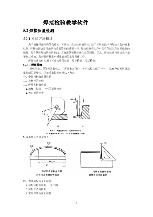
一、金属材料的质量检验二、接材料的检验三、焊件备料的检验1.放样、划线、下料的质量检查2.坡口质量检查3.成形加工的质量检查四、焊件装配质量的检验1.装配结构的检验见下图2.装配工艺的检验3.定位焊缝质量的检验五、焊接的其他工作检查1.焊工考核2.焊接工具的检查5.2.1.2焊中检验1.焊接环境的检查2.焊接规范执行情况的检查3.预热的检查4.焊接后热的检查5.产品试板的质量控制总之:对焊接过程的实时监控,可以帮助我们及时掌握情况,分清责任。
可以避免出现缺陷和减少时间的浪费。
5.2.1.3焊后检验(成品检查)焊缝结构的成品检验属于对产品的终端检验,其检验内容主要有以下几项:1.焊接结构几何尺寸的检查2.焊缝外观检查3.致密性试验和压力试验4.焊缝的表面、近表面及内部缺陷检查1.焊接结构几何尺寸的检查判断焊接结构的几何尺寸是否合格,实际上是判断这些尺寸的公差是否符合要求。
焊接结构上的几何尺寸有两类:一类的在图样上直接给出公差要求,对这类尺寸的检验可直接按图样要求进行检查;另一类是图样上不标公差的尺寸(自由公差),对这类尺寸的检验则应根据不同行业和产品的有关标准进行检查,详见下表2.焊缝外观检查(1)焊缝的目视检测焊缝的外观检测可用肉眼及放大镜,主要检测焊接接头的形状和尺寸,检测过程中可使用标准样板和量规。
EN1290焊缝的无损检测—焊缝的磁粉检测

EN 1290 焊缝的无损检测—焊缝的磁粉检测1. 应用范围本标准规定用磁化法检测铁磁性材料焊缝(包括热影响区)表面缺陷的磁粉探伤方法。
2. 引用标准(略)3. 定义见EN 12062。
4.安全措施应遵循相关的安全和环境保护的规则。
5. 总则5.1 须知进行磁粉探伤前,签约单位应商定检测相关事项,并索取相关技术资料。
5.2 人员资格无损检测人员应按EN 473或有关工业部门的等效标准进行资格鉴定。
5.3 表面状态和准备被检区域不应存在氧化皮、机油、油脂、焊接飞溅、机加工痕迹、厚实或松散的油漆,或其它有可能影响探伤灵敏度的外来杂物。
5.4 磁化5.4.1磁化设备除非另行商定,通常应使用下列交流磁化设备或磁化手段:(1)电磁轭法;(2)触头法;(3)穿棒法或线圈法。
使用直流磁化或永久磁铁,应由签约双方商定。
5.4.2磁化验证对大多数可焊接的铁磁性材料推荐使用2KA/m~6KA/m (有效值)的切向磁场强度。
应采用下列一种方法验证磁场强度:⑴不利部位带有自然或人工小缺陷的工件;⑵霍尔探头测量近表面的切向磁场强度;⑶通过计算,确定近似的切向磁场强度。
如表2、表3中的磁化电流值;⑷采用既定原理为依据的其他验证方法。
5.5 应用方法5.5.1 磁场方向和探测区域缺陷的可检性取决于缺陷主轴相对于磁场方向的夹角。
图1所示是用一个磁场方向来说明的。
为保证各种方向的缺陷均可被检出,对被检焊缝应作两次方向近似垂直(最大偏差30°)的磁化。
可用一次或多次磁化法来达到目的。
只在一个磁场方向进行探伤,应由合同双方商定。
检测过程中应保证被检区域有足够重叠如图2、图3所示。
图3 有效区的重叠图2 磁轭法和触头法磁化时的有效检测区(阴影区) 1.有效区2.重叠区5.5.2典型磁粉探伤方法常见焊接接头型式磁粉探伤法的应用见表1。
其它几何形状的被检焊缝也可参照使用相同的磁化条件,并应满足图1 缺陷可检方向①磁场方向 ②最佳灵敏度 ③灵敏度降低 ④灵敏度不够 α磁场与缺陷方向夹角 αmin缺陷最小可检角 αi 缺陷方向示例下式:d=W1+W2+50式中d——磁通或通电路径(mm);W1——焊缝宽度(mm);W2——热影响区宽度(mm)。
焊接质量的检验方法(2024)
焊接质量的检验方法引言概述:焊接是一种常见的金属连接方式,广泛应用于工业生产和建筑行业。
焊接质量的检验是确保焊接连接的强度和可靠性的重要环节。
本文将详细介绍焊接质量的检验方法,包括非破坏性检测和破坏性检测两大类。
正文内容:一、非破坏性检测方法(1)目测检查:通过肉眼观察焊缝表面情况,检查是否存在焊接缺陷,如裂纹、气孔、夹渣等。
同时还要检查焊缝的外形是否符合规范要求。
(2)磁粉检测:利用磁粉法检查焊接缺陷,先将试件表面涂覆磁粉,然后施加磁场,通过观察磁粉的沉积情况来检测焊接缺陷。
(3)超声波检测:利用超声波检测焊接缺陷,通过送入和接收超声波信号来分析焊缝的内部结构和缺陷情况,如裂纹、气孔等。
(4)液体渗透检测:将试件表面涂覆一层渗透剂,然后用开水或巴布志石等粉末覆盖试件表面,在一定时间内观察渗透液是否透出来,以及是否有色素上浮,来检测焊接缺陷。
(5)射线检测:利用射线(X射线或γ射线)对焊缝进行探测,通过观察照片和比对标准来判断焊接缺陷的存在与否。
二、破坏性检测方法(1)拉伸试验:取一段焊接试样,通过施加拉力来确定焊缝的强度和可靠性。
拉伸试验可以检测焊缝的延伸性、抗拉强度和断裂强度等指标。
(2)扭转试验:取一段焊接试样,通过施加扭矩来确定焊缝的耐久性和可靠性。
扭转试验可以检测焊接结构的耐久性和变形情况。
(3)冲击试验:取一段焊接试样,在低温环境下施加冲击力,来测试焊缝的韧性和抗冲击性能。
冲击试验可以判断焊接结构在低温环境下的使用性能。
(4)硬度试验:通过测量焊缝的硬度来判断焊接结构的质量和可靠性。
硬度试验可以检测焊接材料的变硬情况,从而判断焊接缺陷。
(5)金相检查:通过将焊接试样切割成薄片,经过打磨、腐蚀、染色等处理,观察焊接缺陷和组织结构来判断焊接质量。
金相检查可以检测焊接材料的显微组织和晶粒大小等指标。
总结:焊接质量的检验方法包括非破坏性检测和破坏性检测两大类。
非破坏性检测方法主要包括目测检查、磁粉检测、超声波检测、液体渗透检测和射线检测。
- 1、下载文档前请自行甄别文档内容的完整性,平台不提供额外的编辑、内容补充、找答案等附加服务。
- 2、"仅部分预览"的文档,不可在线预览部分如存在完整性等问题,可反馈申请退款(可完整预览的文档不适用该条件!)。
- 3、如文档侵犯您的权益,请联系客服反馈,我们会尽快为您处理(人工客服工作时间:9:00-18:30)。
EN 1320金属材料焊缝的无损检测-断裂试验
word 格式译文
关键词:焊缝,金属,熔焊,对焊,角焊,检验,结构,缺陷,目测,样件,符号
金属材料焊缝的无损检测
断裂试验
本欧洲标准在1996-09-27由CEN批准。
CEN成员一定要符合CEN/CE NELEC内部规则,规定给予本欧洲标准为国家标准,而不能作任何修改。
关于国家标准的最新的著书名目参考可向中央秘书处或任何CEN成员申请获得。
本标准有三个正式版本(英语,德语,法语)。
任何其它语言的翻译版本在由CEN成员负责下翻译成其本国语言并通知中央秘书处后,可与享受与正式版本同样的地位。
CEN成员为比利时,丹麦,德国,法国,希腊,爱尔兰,意大利,卢森堡,荷兰,挪威,奥地利,葡萄牙,瑞典,瑞士,西班牙和英国的国家标准机构。
名目
前言
用范畴
2.标准参考
3.定义
4.原则
5.名称和缩写
6.样件的大小
7.取样
7.1 概述
7.3 取样
7.4 预备
8. 检验工艺
8.1 对焊
8.2 角焊
8.3 变形熔敷金属的专门讲明
9.检验结果
10. 检验报告
附件A(参考)检验报告
前言
本欧洲标准由CEN、TC121技术委员会制定。
本欧洲标准必须通过出版识别性文本或通过至1997年4月有效的认可保持国家标准的状态。
一些可能与之相对立的标准必须在1997年4月前收回。
使用范畴
本标准规定了样件的大小和进行断裂试验的方法,以获得有关方法,大小和内部不规则性如孔穴,裂纹,未熔合,未焊透和断裂面的固体夹杂物方面的信息。
如果由于使用标准或合同双方的协议有要求,则必须使用本标准。
标准参考
本欧洲标准通过在日期或无日期的参考资料包含了其他出版物的规定。
本标准参考在文本的有关的地点被引用。
在有日期的参考文献中,如果有变更或修改,则均属于对本标准的的变更或修改。
关于无日期的参考文献,则以最近的出版为准。
PrEN970
熔焊无损试验-目测
钢材上弧焊缝-不规则性评估的准则(ISO5817:1992)
EN30042
铝材上的弧焊缝及其适合焊接的铝合金-不规则性评估的准则(ISO10 042:1992)
3.定义
本标准的使用适用于以下定义:
3.1测试长度(Lf):在可能的边缺口之间延焊缝轴测量的样件的长度(见图6)
3.2总长:(∑Lf):在样件侧缺口之间,沿焊缝轴测量的所有测试样件断裂面积的总长
(见图6)
3.3 测试厚度:(αf)每个样件的断裂面的厚度(见图7和8)
3.4 测试面积(Af)出自每个样件测试长度和测试厚度的产品。
3.5 总测试面积(∑Af):所有测试面积的总和。
4.原理
通过熔敷金属焊缝的断裂来判定断裂的面积。
亦可通过弯曲或拉伸在静态或动态负荷下发生断裂。
此外,也可改变缺口的大小和温度,产生断裂。
如未另外规定,测试可在室温下进行(23+/-5)0C。
5.名称和缩写
断裂试验的名称和缩写在表格1中有规定,并在表格5-8中有讲明。
通常情形下只给出差不多名称就够了。
在专门情形下也要求提供额外讲明缺口和试验方法。
表格1:名称和缩写
举例1:
从角焊中取样,测试长度40mm,测试厚度10mm。
-对缺口和测试方法无要求工:
差不多符号:FW/ Lf x af
举例:FW/ 40 X 10
-附加要求(直角上侧纵向缺口和测试方法):
全称:FW/ Lf x af / Fq/图8
举例:FW/40X10/ Fq/图8
举例2:
从对焊中取样,测试长度40mm,测试厚度10mm。
-对缺口和测试方法无要求工:
差不多符号:BW/ Lf x af
举例:BW/ 40 X 10
-附加要求(圆侧缺口和测试方法):
全称:BW/ Lf x af /Sr/图6
举例:FW/40X10/ Sr/图6
6.样件的大小
如在使用标准或合同双方协议中没有另外规定,样件大小必须与图1
-4一致。
必须提供足够数量的试样件,以满足测试总长度(∑Lf)和总面积(∑Af)的需要。
7.取样
7.1概述
测试(Lf)和面积(Af)以及样件的数量必须按照使用标准或合同双方协议来确定。
薄板的焊缝必须与样件的焊缝呈交叉状,各焊缝长度分为相同长度。
焊缝的轴线在对焊时必须保持在样的中心。
只要在使用标准或合同双方协议中没有另外规定,须至少取两次样。
在弯曲试验中,必须有同等数量的样件,它们在拉伸试验中已检测了根侧和上侧。
如果所要求的样件数量的取样的管的直径太小,必须额外焊接试验样件。
7.2 符号
每个样件必须如此标记,即它们在成品取样中或在焊缝中的准确位置必须一致。
在取样时,每个样件必须作标记。
注:关于较高导热性能的材料(如铝和铜)应≥150mm;t为样件厚度。
Abfall:废边
图1:薄板对焊的样件(单位:mm)
注:关于较高导热性能的材料(如铝和铜)应≥150mm;t为样件厚度。
图2:管材对焊的样件(单位:mm)
注:关于较高导热性能的材料(如铝和铜)应≥150mm;t1,t2为样件厚度。
图3:薄板角焊的样件(单位:mm)
注:关于较高导热性能的材料(如铝和铜)应≥150mm;t1,t2为样件厚度,l1,l2为样件长度。
图4:管材角焊的样件(单位:mm)
7.3 取样
7.3.1概述
在取样时,必须使用幸免不利的热或机械阻碍的方法。
通常须去掉样件两端25mm,因为需要关于焊接端部的信息。
(如头和尾和不规则性)。
7.3.2其它金属材料
在其它金属材料中只承诺机械切割。
7.4预备
薄板或管材上焊接的裂口能够用以下一种或多种措施支撑:
-去掉余高
-两个焊缝角的开口(侧缺口)
-在余高处开缺口(纵向缺口)
按照熔敷金属的变形程度能够使用直角,圆角或直角缺口(见图5,6, 7,和8)。
关于变形较大的材质(铝和铜)则举荐用尖角缺口。
缺口的深度必须足够,如此能够产生焊接的裂缝。
只要在使用标准或合同双方协议中没有另外规定,缺口的深度应为以下:
-关于侧缺口,测试长度,Lf必须等于或大于样件原先宽度w(见图6)或总测试长度(∑Lf)的70%的,必须等于或大于样件长度的60%。
-关于纵向缺口:测试厚度,af,必须等于或大于样的原始厚度的80%(见图7)。
图5:缺口形状
注:薄板为拉伸线,管材为点划线
图6:侧缺口
图7a:上侧缺口
注:薄板为拉伸线,管材为点划线
图7b:对焊纵向缺口
图8:角焊的纵向缺口
8.试验方法
8.1 对焊
8.1.1概述
可能通过以下方法进行断裂试验:
-动态冲击,如一个锤子(见图9a,9b,9c);
-使用虎钳,弯曲机或车间压机施加压力(见图9d, 9e, 9f);
-使用拉伸力(见图9g)
关于可变形材质能够是有关心的,当缺口和虎钳钳口之间存在最小距离时。
(见图9c)。
关于有些材质,可在低温下试验以产生缺口。
8.1.2较薄的材质
交替的弯曲有助于使较薄的焊缝断裂。
其极限取决于材质的变形性。
必须将样件压至夹紧钳口,使缺口靠近钳口进行弯曲。
如果未产生断裂,则必须将样件校正到原先形状并重新弯曲。
可用拉伸试验替代弯曲试验(见图9g)。
用锤打击较薄的材质进行断裂试验是不可取的。
8.1.3较厚的材质
关于较厚的材质可用锤子打击,使其断裂。
在使用弯曲机时,必须选择弯曲心棒直径,使之产生断裂,而无需交替弯曲。
按照图9c-9f,关于弯曲所采纳的作用力能够是垂直方向,也能够是与焊缝交叉方向的力。
铝材试验的最低限度约为8mm厚。
8.2角焊
试验方法与对焊相似(见8.1),除此之外,不能够作拉伸试验。
在图1 0中有讲明。
8.3可变形熔敷金属的专门讲明
关于可变形熔敷金属奥氏体钢,铝,铜,镍及其合金,如果要求熔敷金属断裂,则有必要限制样件和角焊的厚度,扩大缺口的宽度,缩小缺口半径,增加打击力度及锤子的力量。
关于可变形熔敷金属如铁素体钢,是有必要将样件再度冷却。
图9a 图9b 图9c 图9d
图9e 图9f 图9g 图9:对焊检验方法举例(缺口按图5-7)schlag:打击
图10a 图10b 图10c
图10:角焊检验方法举例(缺口按照图5-8)
bewegungsrichtung:运动方向;bewegung falls anwendbar:如果有用的话移动
实验结果
断裂面积必须按照EN970进行目测。
为了发觉和识别无缺陷的不规则性,能够使用放大镜(5倍)。
必须完整描述断裂面积的外观,并对可能的不规则性的方式和位置出具一个报告。
必须讲明质量是按照EN25817或EN30042进行评估的。
评估分组必须通过使用人均产值或合同双方的协议来确定。
10.检验报告
检验报告必须包括:
-本标准的参考
-样件的符号
-按照表格1的样件符号
-关于所有不承诺的不规则性的方法,位置和大小的报告
代表性检验报告的举例包括附件A。
