ITX说明书V1.0 HKL 主板 ATOM系列
ITX-M11主板说明书 ver1.0
JP16
JP16 设置 设置
1-2短路 3-4短路 5-6短路 7-8短路 9-10短路 11-12短路
功 能(JP16)
RS232
+5V
COM1
+12V
RS232
+5V +12V
COM2
ห้องสมุดไป่ตู้
ITX-M11 基于 Intel® IVY bridge 架构的 Mini-ITX 主板
3 1
JBAT
设置
功能
1-2短路
正常工作状态
2-3短路 清除CMOS内容,所有BIOS设置恢复成出厂值
2、硬件来电自启功能设置(JPW1) 该板支持硬件来电自启功能,默认为关闭状态。具体设置方式如下:
3 1
JPW1
设置 1-2短路 2-3短路
功能 关闭来电自启功能 打开来电自启功能
6、SATA2与SATA3功能设置 SATA2接口与SATA3(2.5寸笔记本硬盘位)只能支持二选一,具体设置方
式如下:
R243
R185
R148
R158
3
1
将R243、R185、R148、R158 4个电阻焊接到1-2为支持SATA3(2.5寸笔记 本硬盘位)
将R243、R185、R148、R158 4个电阻焊接到2-3为支持SATA2接口
器,具有超强的图形处理能力及应用计算能力,是一款低功耗、高性能、 结 构 紧 凑 的 高 清 播 放 主 板 , 采 用 Intel® HM65 高 速 芯 片 组 , 支 持 DDR Ⅲ 1333/1066MHz内存,最大可支持8GB,内部集成Intel® HD Graphics核心显 卡,提供高性能的显示输出,支持VGA\LVDS\双HDMI显示输出,同时使用可 实现独立双显示,集成1个RTL千兆网卡,2个MPCIE插槽支持WIFI\SSD\3G模 块,1个2.5寸笔记本硬盘位,2个SATA硬盘接口。
ITX 系列主板使用说明

2.2.6 JP7 跳线说明 (1)针对 COM1 跳线
COM1 com 接(预设)
PIN9 5V 带电 PIN9 12V 带电
JP7 跳至 5-6 脚 跳至 1-2 脚 跳至 3-4 脚
11
2.2.7 JC26 插针 主机板提供了 1 组 JC26 插针,控制 COM2/COM3/COM4/COM5/
b.PWRLED 电源指示灯 d.PWRSW ATX 电源开关
主机板提供了 1 组 F_PANEL 插针,其信号定义图如下所示:
v SPEAKER 喇叭连接头 电脑的喇叭连接头(也称蜂鸣器)共有四个脚位,只要把机箱上的喇叭接头 接至此四脚位上即可使用。
v PWRLER 电源指示灯 电源指示灯为三个脚位的连接头,用来指示电脑的工作状态,当电脑一旦 上电时,指示灯常亮,反之,则不亮(注:有正负之分)。
当将风扇连接到风扇连接头上时,使用者必须将红色的线连接到 +12V 的电源针上,黑色的线连接到地线上。如果您想在 BIOS 或硬件监控 程序中观察风扇的工作状态,您必须使用支持能侦测转速功能的风扇。对 于具有速度感应器的风扇,风扇每一次转动都会产生 2 个脉冲波,系统硬 件监控将作统计逼供内产生一个风扇转动速度的报告,可在 CMOS 中显示 出风扇的转速。
结构及 尺寸
工作温度 工作湿度 应用范围
IP 3 0 X 3 产 品 规 格
Intel ATOM 230 双 核 处 理 器
FSB 533MHz INTEL 945GC +ICH7 1 x DDR2 6 6 7/53 3 M H z D IM M , 最 大 容 量 支 持 2GB 集 成 GMA950 图 形 加 速 器 板 载 Realtek ALC662 HD 音 效 芯 片 板 载 Realtek 8111D 双 网 卡 , 支 持 无 盘 2 x SATA 3 Gb/s 磁 盘 接 口 1 x PCI 插 槽 支 持 8 个 USB 2.0 端 口 (4 个 需 要 扩 展 ) 1 x 24-pin ATX 主 电 源 接 口 2 x SATA SATA 磁 盘 接 口 1 x CPU fan header CPU 风 扇 接 口 1 x SYS fan header 系 统 风 扇 接 口 1 x front panel header 前 置 面 板 插 针 1 x Audio header 前 置 音 频 跳 线 插 针 2 x USB 2.0 headers USB 扩 展 插 针 1 x Clear CMOS Header 清 CMOS 插 针 1 x VGA-H 插 针 , 1 x Mini IDE 接 口 5 x COM 扩 展 插 针 , 1 组 COM 状 态 控 制 插 针 1 x IR 红 外 线 扩 展 插 针 1 x PS/2 鼠 标 端 口 , 1 x PS/2 键 盘 端 口 1 x VGA 端 口 , 1 x COM 端 口 1 x LPT 端 口 4 x USB 2.0 端 口 2 x RJ-45 网 卡 端 口 2 x audio 接 口 (6 声 道 音 频 接 口 )
ITX 系列主板 说明书

ITX系列用户手册你现选用的产品型号为:Rev:1.01Date:2009.02安全指导商标声明所有的品牌,产品,徽标,商标和公司名称都是属于商标或注册商标各自的拥有者。
AMI®是AMI 公司的注册商标。
Intel ® ,Celeron ® ,Pentium ®是 Intel 公司的注册商标。
Netware ®是Novell Inc.的注册商标。
PS/2 和 OS/2 是International Business Machines 公司的注册商标。
Windows ®98/ 2000/NT/XP 和Microsoft ®是Microsoft 公司的注册商标。
01. 务必请仔细通读本安全指导.02. 务必请妥善保管本手册,以备将来参考.03. 请保持本设备的干燥.04. 机箱的开口缝隙是用于通风避免机箱内的部件过热,请勿将此类开口掩盖或堵塞.05. 在将本设备与电源连接前,请确认电源电压值,将电压调整为110V/220V.06. 请将电源置于不会被践踏到的地方,并且不要在电源线上堆置任何实物.07. 插拔任何扩展卡或设备模块前,请将电源线拔下.08. 请留意手册上提到的所有注意和警告事项.09. 通电之前请确认主机箱中不要遗留螺丝等金属物件,以免电气短路烧毁其他部件.10.不得将任何液体倒入机箱开口的缝隙中,否则会产生严重损坏或电路瘫痪.11.如果发生以下情况,请找专业人员处理:v 电源线或插头损坏v 液体渗入机器内v 机器暴露在潮湿的环境中v 机器工作不正常或用户不能通过本手册的指导使其正常工作v 机器跌落或受创v 机器有明显的破损迹象目录安全指导......................................................................2商标声明......................................................................2第一章 主板简介及规格说明 (4)1.1 包装盒内物品清单.........................................................................................41.2 主板LAYOUT 图及规格表. (5)第二章 硬件设备的安装说明 (8)2.1 中央处理器的安装........................................................................................82.2 CPU 风扇的安装...........................................................................................92.3 内存的安装...................................................................................................112.4 主板跳线的设定说明.....................................................................................112.5 主机板接头说明 (12)第三章 BIOS 简介 (17)3.1 B IOS 升级更新..............................................................................................173.2 B IOS 设定.....................................................................................................173.3 B IOS 语言切换. (18)第四章 驱动程序的安装 (19)4. 1 芯片组驱动程序的安装...............................................................................194. 2 板载显卡驱动的安装...................................................................................194. 3 板载网卡驱动的安装...................................................................................194. 4 板载声卡驱动的安装...................................................................................194. 5 USB2. 0驱动程序的安装. (19)ITX-M4S1LAITX-M4S1LA-2主板规格如下表:步骤三 卸下CPU 保护盖,确认主机板上特别设计的 Socket 底座的2个凸出位置及CPU 的2个定位凹口位置方向对准后,将CPU 轻轻平放置入Socket 中,如果两者方向未对准CPU 将无法置入Socket 中。
代号阿童木英特尔Atom平台性能实测_IntelCPU评测-泡泡网
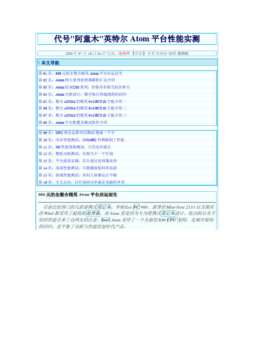
代号"阿童木"英特尔Atom平台性能实测2008年07月16日 04:57 出处:泡泡网【原创】作者:张柏松编辑:张柏松本文导航第01页:666元的全整合精英Atom平台应运而生第02页:Atom两大系列处理器解析汇总介绍第03页:Atom的N2X0系列:价格具有相当的亲和力第04页:Atom全新设计:顺序执行和超线程的回归第05页:整合ATOM的精英945GCT-D主板介绍一第06页:整合ATOM的精英945GCT-D主板介绍二第07页:整合ATOM的精英945GCT-D主板介绍三第08页:Atom平台配置及测试软件介绍第09页:CPU理论运算对比测试:慢就一个字第10页:内存性能测试:533MHZ外频限制了性能第11页:3D性能基准测试:只比没有强点第12页:整机功耗测试:仅相当于一个灯泡第13页:平台温度实测:芯片竟比处理器还热第14页:高清性能测试:只能播放低码率高清第15页:游戏性能测试:冰封王座都运行不畅第16页:全文总结:以灯泡的功率满足电脑的享受666元的全整合精英Atom平台应运而生目前比较热门的几款便携式笔记本,华硕Eee PC 900,惠普的Mini-Note 2133以及微星的Wind都采用了超低耗处理器。
而Atom更是因为专为便携式笔记本设计,低功耗以及不俗的性能引来了众网友的注意。
Intel Atom采用了一个全新的X86 CPU架构,是顺序架构的回归,是平衡了功耗与性能的划时代产品。
Atom处理器的优势• 价格方面:Atom N230 售价只有29美元•超低功耗需求• 超频性能好,且对整体功耗提升不明显Atom处理器的缺点•整体性能偏弱• 芯片组性能不好• 3D性能极差• 目前无合理的平台可更换随着制造商们开发基于英特尔“凌动”处理器的上网本和上网机产品。
这款售价仅为666元的全整合精英ECS P45GCT-D平台也随之营运而生,如此一来只需外加1G内存和160G 硬盘,就完全可以打造出千元出头的上网主机体,一台家电的价格就可以享受电脑的功能。
优质文档惠普瘦客户机ThinClient产品与使用介绍

瘦客户机采用Linux 精简型操作系统或Microsoft Windows Embedded 操作系统家族,包括Linux Embedded,和Microsoft Windows XP Embedded (wes09、WES 7)操作系统。
HP瘦客户机的特性和应用范围
安全
计算
可扩展
可靠
3
节能
管理
电信 金融服务 制造业 零售业 医疗保健 教育 政府与国防
• 瘦客户机精简的3个主要方面
− 硬件的精简: − 系统的精简: − 维护工作量和能耗的精简
• 安全性的保证
− EWF锁 − Sygate防火墙
• 管理的方便(免费附赠)
− Device Manager管理工具 − HP Thin State
主要功能1:安全性的提升
增强的安全性能
• 将重要数据都存储在安全的服务器上 • 将所有的设置存储于服务器加强了安全性和可管理
灵活型 t5740 – Windows Embedded Standard 2009
功能全面, 最高效!
t5740
配置
OPERATING SYSTEM: PROTOCOLS:
SUPPORTED BROKERS:
Microsoft Windows Embedded Standard 2009
GEMTECH ITX-8978 主板 说明书
主板后面板提供以下接口:
6
VGA接口
主板提供一个DB 15-pin母头接口以连接到一个VGA监视器。
DVI接口
主板提供一个DVI-D接口以连接到一个DVI监视器。
HDMI接口
主板提供一个HDMI 1.3接口以连接到一个HDMI监视器。
SPDIF接口
主板提供两个 S/PDIF 接口,一个是同轴输出(Coaxial Out),一个是光线输出(Optical Out)。
主板使用12V 5A 的适配器电源供应器给主板供电。在连接电源供应器之前,请务必确认所有的 组件都已正确安装,并且不会造成损坏。
另外,也可用ATX 12V电源接口PW1 为主板供电。在与ATX 电源供应器相连时,请务
必确认,电源供应器的接头安装方向正确,针脚对应顺序也准确无误。将电源接头插入,并使其 与主板电源接口稳固连接。 以上两种供电方式选择一种即可。
使用手册
版本 1.1 发行日期 2009年九月
安全指导
1. 务必请仔细通读本安全指导。 2. 务必请妥善保管本手册,以备将来参考。 3. 请保持本设备的干燥。 4. 在使用前,宜将本设备置于稳固的平面上。 5. 机箱的开口缝槽是用于通风,避免机箱内的部件过热。请勿将此类开口掩盖 或堵塞。 6. 在将本设备与电源连接前,请确认电源电压值,将电压调整为110/220V。 7. 请将电源线置于不会被践踏到的地方,并且不要在电源线上堆置任何物件。 8. 插拔任何扩展卡或模块前,请都将电源线拔下。 9. 请留意手册上提到的所有注意和警告事项。 10. 不得将任何液体倒入机箱开口的缝槽中,否则会产生严重损坏或电路瘫痪。 11. 如果发生以下情况,请找专业人员处理:
Expansion Slot
沃斯海尔IO扩展板用户手册说明书

XBee of MaxStream is a wireless communication module based on ZigBee technology. In an easy-to-use design, it can automatically transmit the inputted data to another XBee module by wireless connection. And it also supports AT commands for advance configuration.
o VCC : power positive o GND : ground o D : digital pin, correspond to the
Arduino board 5. WIFI-LPT100 connector 6. 4-pin sensor interface
o VCC : power positive o GND : ground o A : analog pin, correspond to the
2) Insert the XBee-A into the XBee interfaces of IO Expansion Shield-A, and insert the XBee-B into the XBee interfaces of IO Expansion Shield-B respectively.
Waveshare
3.1 Preparations
One WIFI-LPT100 module Two Arduino development boards Two XBee modules Two IO Expansion Shields TCP232 serial software
H610M-ITX eDP UEFI SETUP UTILITY 使用手册说明书

H610M-ITX/eDPUEFI SETUP UTILITY1 简介本节介绍如何使用 UEFI SETUP UTILITY 配置您的系统。
打开计算机电源后按 <F2> 或 <Del> ,您可以运行 UEFI SETUP UTILITY,否则,开机自检 (POST)将继续其测试例程。
如果您想要在 POST 后进入 UEFI SETUP UTILITY,可按<Ctl> + <Alt> + <Delete> 或按系统机箱上的重置按钮重新启动系统。
也可以通过关闭系统后再开启来重新启动它。
由于 UEFI 软件在不断更新,因此以下 UEFI 设置屏幕和说明仅供参考,并且可能与您在自己屏幕上看到的内容不同。
122 EZ 模式默认情况下,进入 BIOS 设置程序时,EZ Mode ( EZ 模式)屏幕会出现。
EZ 模式是一个仪表盘,包含系统当前状态的多个读数。
您可以检查系统最重要的信息,如:CPU 速度、DRAM 频率、SATA 信息、风扇速度等。
按 <F6> 或单击屏幕右上角的“Advanced Mode (高级模式)”按钮可以切换到“高级模式”,访问更多选项。
编号功能1Help (帮助)2Load UEFI Defaults (加载 UEFI 默认值)3Save Changes and Exit (保存更改并退出)4Discard Changes (放弃更改)5Change Language (更改语言)6Switch to Advanced Mode (切换到高级模式)简体中3H610M-ITX/eDP3 高级模式高级模式提供更多选项来配置 BIOS 设置。
请参阅以下部分了解详细配置。
要访问 EZ 模式,请按 <F6> 或单击屏幕右上角的“EZ Mode (EZ 模式)”按钮。
3.1 UEFI 菜单栏屏幕上部有一个菜单栏包含以下选项:主画面设置系统时间/日期信息3.2 导航键使用 < > 键或 < > 键选择菜单栏上的选项,并使用 < > 键或 < > 键上下移动光标以选择项目,然后按 <Enter> 进入子屏幕。
戴尔易安信刀片式服务器I O指南说明书

INFINIBAND
GbE M6220
3032
M6348
M8024 10GbE
FC4
FC4
FC8
M2401G
M3601Q
Pass
3130G
Pass
Pass M4424 M5424
DDR
QDR
DELTLhrCuONFIDENTIAL 3130X
Thru
Thru
Infiniband Infiniband
Cables CX4 cable, InfiniBand 4x connector
10GbE X2 Transceiver
Modules
MMF, dual SC
connector
10GbE X2 Transceiver
Modules
10GBASE-SR X2 Module
10GBASELRM X2 Module
4
POWERCONNECT M6220
PE server blade I/O
card
Uplinks
Uplinks
Transceivers XFP Optical Transceiver 10GBASE-LR, LC Connector XFP Optical Transceiver 10GBASE-SR, LC Connector
4 Copper
I/O bays
Fabric A1 &
A2
Fabric B1 &
B2
Fabric C1 &
C2
5
CISCO BLADE SWITCH
PE server blade I/O
card
Use Broadcom 5709 dual port server blade I/O Mezzanine Cards in PE blade servers for
ITX-M50 VER 2.2(2015.10.15)主板说明书

Intel○R Bay Trail Processor ITX-M50 VER:2.2说明除列明随产品配置的配件外,本手册包含的内容并不代表本公司的承诺,本公司保留对此手册更改的权利,且不另行通知。
对于任何因安装、使用不当而导致的直接、间接、有意或无意的损坏及隐患概不负责。
订购产品前,请向经销商详细了解产品性能是否符合您的需求。
本手册所涉及到的其他商标,其所有权为相应的产品厂家所拥有。
本手册内容受版权保护,版权所有。
未经许可,不得以机械的、电子的或其它任何方式进行复制。
订购信息温馨提示1、产品使用前,务必请仔细阅读产品说明书。
2、对未准备安装的主板,应将其保存在防静电保护袋中。
3、在从包装袋中拿主板前,应将手先置于接地金属物体上一会儿,以释放身体及手中的静电4、在使用前,宜将主板置于稳固的平面上。
5、请保持主板的干燥,散热片的开口缝槽是用于通风,避免机箱内的部件过热。
请勿将此类开口掩盖或堵塞。
6、在将主板与电源连接前,请确认电源电压值。
7、请将电源线置于不会被践踏的地方,且不要在电源线上堆置任何物件。
8、当您需连接或拔除任何设备前,须确定所有的电源线事先已被拔掉。
9、为避免人体被电击或产品被损坏,在每次对整机、板卡进行拔插或重新配置时,须先关闭交流电源或将交流电源线从电源插座中拔掉。
10、请留意手册上提到的所有注意和警告事项。
11、为避免频繁开关机对产品造成不必要的损伤,关机后,应至少等待30秒后再开机。
12、设备在使用过程中出现异常情况,请找专业人员处理。
13、请不要将本设备置于或保存在环境温度高于70℃上,否则会对设备造成伤害。
注意:如果电池换置不当,会产生爆炸的危险。
请务必使用同一型号的或者相当类型的且为制造商推荐的电池。
目录第一章产品介绍................................................................................................... - 4 -1.1 产品规格 .................................................................................................. - 5 - 第二章安装说明................................................................................................. - 10 -2.1 主板尺寸图............................................................................................. - 10 -2.2 接口位置示意图...................................................................................... - 11 -2.3 安装步骤 ................................................................................................ - 12 -2.4 内存安装 ................................................................................................ - 12 -2.5 跳线功能设置 ......................................................................................... - 12 -2.5.1 CMOS内容清除/保持设置(JBAT1).................................................. - 12 -2.5.2 JPW1选择跳线..................................................................................... -12 -2.5.3 SATA2、SATA5接口功能设置(SATA1_SW1) .................................. -12 -2.6 接口说明 ................................................................................................ - 14 -2.6.1 SATA接口(SATA2、PWROUT1) .............................. 错误!未定义书签。
MS-9832 微星miniITX工控主板说明书 用户手册
G52-98321X1Copyright NoticeThe material in this document is the intellectual property of M ICRO-STAR INTERNATIONAL. We take every care in the preparation of this document, but no guarantee is given as to the correctness of its contents. Our products are under continual improvement and we reserve the right to make changes without notice.TrademarksAll trademarks are the properties of their respective owners.Intel® and Pentium® are registered trademarks of Intel Corporation.AMD, Athlon™, Athlon™ XP, Thoroughbred™, and Duron™ are registered trade-marks of AMD Corporation.NVIDIA, the NVIDIA logo, DualNet, and nForce are registered trademarks or trade-marks of NVIDIA Corporation in the United States and/or other countries.PS/2 and OS®/2 are registered trademarks of International Business Machines Corporation.Windows® 98/2000/NT/XP/Vista are registered trademarks of Microsoft Corporation. Netware® is a registered trademark of Novell, Inc.Award® is a registered trademark of Phoenix Technologies Ltd.AMI® is a registered trademark of American Megatrends Inc.Revision HistoryRevision Revision History DateV1.0First release September 2008Technical SupportIf a problem arises with your system and no solution can be obtained from the user’s manual, please contact your place of purchase or local distributor. Alternatively, please try the following help resources for further guidance.Contact our technical staff at .Safety Instructions1.Always read the safety instructions carefully.2.Keep this User’s Manual for future reference.3.Keep this equipment away from humidity.y this equipment on a reliable flat surface before setting it up.5.The openings on the enclosure are for air convection hence protects the equip-ment from overheating. DO NOT COVER THE OPENINGS.6.Make sure the voltage of the power source and adjust properly 110/220V be-fore connecting the equipment to the power inlet.7.Place the power cord such a way that people can not step on it. Do not placeanything over the power cord.8.Always Unplug the Power Cord before inserting any add-on card or module.9.All cautions and warnings on the equipment should be noted.10.Never pour any liquid into the opening that could damage or cause electricalshock.11.If any of the following situations arises, get the equipment checked by servicepersonnel:The power cord or plug is damaged.Liquid has penetrated into the equipment.The equipment has been exposed to moisture.The equipment does not work well or you can not get it work according toUser’s Manual.The equipment has dropped and damaged.The equipment has obvious sign of breakage.12. DO NOT LEAVE THIS EQUIPMENT IN AN ENVIRONMENT UNCONDITIONED, STOR-AGE TEMPERATURE ABOVE 600 C (1400F), IT MAY DAMAGE THE EQUIPMENT.CAUTION: Danger of explosion if battery is incorrectly replaced.Replace only with the same or equivalent type recommended by themanufacturer.FCC-B Radio Frequency Interference StatementThis equipment has beentested and found to complywith the limits for a Class Bdigital device, pursuant to Part15 of the FCC Rules. These limits are designed to provide reasonable protection against harmful interference in a residential installation. This equipment generates, uses and can radiate radio frequency energy and, if not installed and used in accor-dance with the instructions, may cause harmful interference to radio communications. However, there is no guarantee that interference will not occur in a particular installation. If this equipment does cause harmful interference to radio or television reception, which can be determined by turning the equipment off and on, the user is encouraged to try to correct the interference by one or more of the measures listed below.Reorient or relocate the receiving antenna.Increase the separation between the equipment and receiver.Connect the equipment into an outlet on a circuit different from that towhich the receiver is connected.Consult the dealer or an experienced radio/television technician for help.Notice 1The changes or modifications not expressly approved by the party responsible for compliance could void the user’s authority to operate the equipment.Notice 2Shielded interface cables and A.C. power cord, if any, must be used in order to comply with the emission limits.VOIR LA NOTICE D’INSTALLATION AVANT DE RACCORDER AU RESEAU.Micro-Star InternationalMS-9832This device complies with Part 15 of the FCC Rules. Operation is subject to the following two conditions:(1) this device may not cause harmful interference, and(2) this device must accept any interference received, including interference thatmay cause undesired operation.WEEE (Waste Electrical and Electronic Equipment) StatementCONTENTSCopyright Notice (ii)Trademarks (ii)Revision History (ii)Technical Support (ii)Safety Instructions (iii)FCC-B Radio Frequency Interference Statement (iv)WEEE (Waste Electrical and Electronic Equipment) Statement (v)Chapter 1 Product Overview................................................................................1-1 Mainboard Specifications...................................................................................1-2 Block Diagram.......................................................................................................1-4 Mainboard Layout................................................................................................1-5 Board Dimension..................................................................................................1-6 Back Panel & I/O Shield Drawing........................................................................1-7 Power Consumption............................................................................................1-8 Safety Compliance & MTBF..............................................................................1-10 Chapter 2 Hardware Setup....................................................................................2-1 Quick Components Guide....................................................................................2-2 Memory.................................................................................................................2-3 Power Supply......................................................................................................2-4 Back Panel I/O......................................................................................................2-5 Connector............................................................................................................2-7 Jumper................................................................................................................2-13 Slot......................................................................................................................2-15 Chapter 3 BIOS Setup.............................................................................................3-1 Entering Setup.....................................................................................................3-2 The Main Menu.....................................................................................................3-4 Standard CMOS Features...................................................................................3-6 Advanced BIOS Features...................................................................................3-9 Integrated Peripherals.......................................................................................3-13 Power Management Setup...............................................................................3-16 PnP/PCI Configurations......................................................................................3-19 H/W Monitor........................................................................................................3-21 Load Fail-Safe / Optimized Defaults................................................................3-22 BIOS Setting Password.....................................................................................3-23 Chapter 4 System Resources.............................................................................4-1 Watch Dog Timer Setting.....................................................................................4-2 AMI POST Code...................................................................................................4-3 Resource List......................................................................................................4-7Product OverviewProduct Overview1-31-4Product Overview Mainboard LayoutIM-945GC (MS-9832 v1.X) Mini ITX MainboardIM-945GC-D (MS-9832 v1.X) Mini ITX Mainboard1-51-61-7Product OverviewBack Panel & I/O Shield Drawing1-8Product OverviewComponent DescriptionCPU Intel® Atom™ Processor 200 SeriesMemory Corsair 1G DDR2-800 x1Add-On VGA NAHard Disk Western 80G IDE 7200rpm HDD x1Operating system Microsoft® Windows XP®Professional SP2MS-9832 (DC) 12V inputCurrent(A) WattEnter DOS (Stable) 1.613 A 19.356WEnter BIOS (Stable) 1.600 A 19.200WIdle 1.578 A 18.936WCPU Stress 100% 1.760 A 21.120WWindowsstress(3dMARK2002.213 A 26.556W6)Windows DesktopStandby S1 without1.270 A 15.240WLAN connected(stable)Windows DesktopStandby S3 without0.240 A 2.880WLAN connected(stable)Windows DesktopHibernate S40.175 A 2.100Wwithout LANconnected (stable)Windows DesktopSoft Off S5 without0.188 A 2.256WLAN connected(stable)1-91-10Calculation ModelOperationTemperature (°C)OperatingEnvironmentDuty Cycle (FITs.) MTBF (hr.) Telcordia Issue 1 25GB, GC - GroundBenign,Controlled3,480.218071 287,3389832-02S MTBF - Reliability PredictionCalculation ModelOperationTemperature (°C)OperatingEnvironmentDuty Cycle (FITs.) MTBF (hr.)Telcordia Issue 1 25 GB, GC - GroundBenign,Controlled3,657.522543 273,409HardwareSetup2-1PCI1, p.2-14 2-2MemoryDDR2240-pin, These DIMM slots are intended for system memory modules.Installing Memory Modules1.Locate the DIMM slots on the mainboard. Flip open the retaining clip at each sideof the DIMM slot.2.Align the notch on the DIMM with the key on the slot. Insert the DIMM vertically intothe DIMM slot. Then push it in until the golden finger on the DIMM is deeply inserted in the DIMM slot. The retaining clip at each side of the DIMM slot will automatically close if the DIMM is properly seated.3.Manually check if the DIMM has been locked in place by the retaining clips at thesides.PIN SIGNAL 1GND 2GND 312V 412VPin DefinitionSystem Power Connector: JPW1 (for IM-945GC-D)This 12V power connector is used to provide power to the system & CPU.SATA HDD Power Connector: JPWR2 (for IM-945GC-D)These connectors provide power to the SATA hard disk drives.JPW11342JPWR2GND GND +12V VCC5Back Panel I/OSpeed I ndicatorActivity IMouse/KeyboardThe standard PS/2® mouse/keyboard DIN connector is for a PS/2® mouse/keyboard. Serial PortThe serial port is a 16550A high speed communications port that sends/ receives 16bytes FIFOs. You can attach a serial mouse or other serial devices directly to the connector.VGA PortThe DB15-pin female connector is provided for monitor.USB PortThe USB (Universal Serial Bus) port is for attaching USB devices such as keyboard,mouse, or other USB-compatible devices. LANThe standard RJ-45 LAN jack is for con-nection to the Local Area Network (LAN).You can connect a network cable to it.Keyboard USB Ports CONN1USB Ports VGA PortMICCONN2CONN2Serial PortConnectorIDE Connector: IDE1This connector supports IDE hard disk drives, optical disk drives and other IDE devices.IDE1nect to one Serial ATA device.SATA1SATA3SATA2SATA4Fan Power Connector: CPUFAN1, SYSFAN1The fan power connectors support system cooling fan with +12V. When connecting the wire to the connectors, always note that the red wire is the positive and should be connected to the +12V; the black wire is Ground and should be connected to GND.If the mainboard has a System Hardware Monitor chipset onboard, you must use a specially designed fan with speed sensor to take advantage of the CPU fan control.Serial Port Connector: COM1, COM2, COM3This connector is a 16550A high speed communications port that sends/receives 16bytes FIFOs. You can attach a serial device to it through the optional serial port bracket.Pin DefinitionCOM219210 COM110291 COM319210SYSFAN1FAN_RPM+12VGND CPUFAN1F A N _R P M +12VG N DF A N _P W MPin DefinitionFront Panel Connector: JFP1The mainboard provides one front panel connector for electrical connection to the front panel switches and LEDs. The JFP1 is compliant with Intel ® Front Panel I/O Connectivity Design Guide.JFP1LED Reset Switch Power Power2-13Hardware SetupClear CMOS Jumper: JBAT1There is a CMOS RAM onboard that has a power supply from an external battery to keep the data of system configuration. With the CMOS RAM, the system can auto-matically boot OS every time it is turned on. If you want to clear the system configuration,set the jumper to clear data.JumperClear Data1Keep Data1JBAT112-141+5V +12V JCOMP2(for COM2)2-15Hardware SetupSlotPCI (Peripheral Component Interconnect) Express SlotThe CON1 is Mini PCI-E connector for wireless LAN, TV tuner, and Robson NAND Flash.PCI (Peripheral Component Interconnect) SlotThe PCI slot supports LAN card, SCSI card, USB card, and other add-on cards that comply with PCI specifications.32-bit PCI SlotMini PCI-E SlotThis page is intentionally left blank.viiiBIOS Setup3-13-2BIOS Setup 3-3Getting HelpAfter entering the Setup menu, the first menu you will see is the Main Menu.Main MenuThe main menu lists the setup functions you can make changes to. You can use the arrow keys ( ↑↓ ) to select the item. The on-line description of the highlighted setup function is displayed at the bottom of the screen.Sub-M enuIf you find a right pointer symbol (as shown in the right view)appears to the left of certain fields that means a sub-menu canbe launched from this field. A sub-menu contains additional op-tions for a field parameter. You can use arrow keys ( ↑↓ ) to highlight the field and press <Enter> to call up the sub-menu. Then you can use the control keys to enter values and move from field to field within a sub-menu. If you want to return to the main menu, just press the <Esc >.General Help <F1>The BIOS setup program provides a General Help screen. Y ou can call up this screen from any menu by simply pressing <F1>. The Help screen lists the appropriate keys to use and the possible selections for the highlighted item. Press <Esc> to exit the Help screen.Control Keys3-4Standard CMOS FeaturesUse this menu for basic system configurations, such as time, date etc.Use this menu to setup the items of AMI ® special enhanced features.Integrated PeripheralsUse this menu to specify your settings for integrated peripherals.Power Management SetupUse this menu to specify your settings for power management.PnP/PCI ConfigurationsUse this menu to specify PnP/PCI settings.H/W MonitorThis entry shows your PC health status.Use this menu to load the default values set by the BIOS vendor for stable system performance.BIOS SetupLoad Optimized DefaultsUse this menu to load the default values set by the mainboard manufacturer specifi-cally for optimal performance of the mainboard.BIOS Setting PasswordUse this menu to set the password for BIOS.Save changes to CMOS and exit setup.Exit Without SavingAbandon all changes and exit setup.3-53-6 Date (MM:DD:YY)This allows you to set the system to the date that you want (usually the current date).The format is <day> <month> <date> <year>.day Day of the week, from Sun to Sat, determined byBIOS. Read-only.month The month from Jan. through Dec.date The date from 1 to 31 can be keyed by numeric function keys.year The year can be adjusted by users.Time (HH:MM:SS)This allows you to set the system time that you want (usually the current time). The time format is <hour> <minute> <second>.This setting specifies the operation mode of the ATA/IDE device.Vender, SizeThese settings show the IDE/SATA device information. Read only.LBA/Large ModeThis setting allows you to enable or disable the LBA Mode. Setting to [Auto]enables LBA mode if the device supports it and has not been formatted withLBA mode disabled.This setting specifies the DMA Mode.Hard Disk S.M.A.R.T.This setting allows you to activate the S.M.A.R.T. (Self-Monitoring Analysis &Reporting Technology) capability for the hard disk drives. S.M.A.R.T is a utilitythat monitors your disk status to predict hard disk failure. This gives you anopportunity to move data from a hard disk that is going to fail to a safe placebefore the hard disk becomes off-line.Boot Sector ProtectionThe item is to set the Virus Warning feature for IDE Hard Disk boot sector protection.If the function is enabled and any attempt to write data into this area is made, BIOSwill display a warning message on screen and beep.Setting the item to [Enabled] allows the system to boot within 5 seconds since it willskip some check items.This setting is to set the Num Lock status when the system is powered on. Setting to[On] will turn on the Num Lock key when the system is powered on. Setting to [Off]will allow users to use the arrow keys on the numeric keypad.This field is used to enable or disable the APIC (Advanced Programmable Interrupt Controller). Due to compliance with PC2001 design guide, the system is able to run in APIC mode. Enabling APIC mode will expand available IRQ resources for the system. MPS Table VersionThis field allows you to select which MPS (Multi-Processor Specification) version to be used for the operating system. You need to select the MPS version supported byAdvanced BIOS FeaturesFunctionThe processor uses Hyper-Threading technology to increase transaction rates and reduces end-user response times. The technology treats the two cores inside the processor as two logical processors that can execute instructions simultaneously. In this way, the system performance is highly improved. If you disable the function, the processor will use only one core to execute the instructions. Please disable this item if your operating system doesn ’t support HT Function, or unreliability and instability may occur.Intel's Execute Disable Bit functionality can prevent certain classes of malicious "buffer overflow" attacks when combined with a supporting operating system.This functionality allows the processor to classify areas in memory by where application code can execute and where it cannot. W hen a malicious worm attempts to insert code in the buffer, the processor disables code execution,preventing damage or worm propagation.This setting sets Max CPUID extended function value to 3.Chipset FeatureThe High Precision Event Timer (HPET) was developed jointly by Intel and Microsoft to meet the timing requirements of multimedia and other time-sensitive applications.In addition to extending the capabilities and precision of a system, the HPET also improves system performance.VGA Share MemoryThe system shares memory to the onboard VGA card. This setting controls the exact memory size shared to the VGA card.DVMT Mode SelectIntel's Dynamic Video Memory Technology (DVMT) allows the system to dy-namically allocate memory resources according to the demands of the system at any point in time. The key idea in DVMT is to improve the efficiency of the memory allocated to either system or graphics processor.It is recommended that you set this BIOS feature to DVMT Mode for maximum performance. Setting it to DVMT Mode ensures that system memory is dynami-cally allocated for optimal balance between graphics and system performance.When set to DVMT/FIXED Mode, the graphics driver will allocate a fixed amount of memory as dedicated graphics memory, as well as allow more system memory to be dynamically allocated between the graphics proces-sor and the operating system.1st Boot DeviceThe items allow you to set the first boot device where BIOS attempts to load the disk operating system.Boot From Other DeviceSetting the option to [Yes] allows the system to try to boot from other device. if the system fails to boot from the 1st boot device.USB Controller This setting allows you to enable/disable the onboard USB 1.1/ 2.0 controller. Onboard LAN ControllerThis setting allows you to enable/disable the onboard LAN controller.The items enable or disable the initialization of the onboard LAN Boot ROM during bootup. Selecting [Disabled] will speed up the boot process.Integrated PeripheralsOn-Chip IDE ControllerThis setting enables/disables the onchip IDE controller.PCI IDE BusMasterSet this option to [Enabled] to specify that the IDE controller on the PCI local bus has bus mastering capability.On-Chip SATA ControllerThis setting enables/disables the onchip SATA controller.COM Port 1, COM Port1 Mode, COM Port 2, Serial Port 3/ 4/ 5/ 6Address, Serial Port 3/ 4/ 5/ 6 IRQThese settings specify the base I/O port address and IRQ resource of the onboard serial ports.You can enable the system watch-dog timer, a hardware timer that generates either an NMI or a reset when the software that it monitors does not respond as expected each time the watch dog polls it.ACPI FunctionThis item is to activate the ACPI (Advanced Configuration and Power Management Interface) Function. If your operating system is ACPI-aware, such as Windows 98SE/2000/ME/ XP, select [Enabled].This item specifies the power saving modes for ACPI function. If your operating system supports ACPI, such as Windows 2000/ XP , you can choose to enter the Standby mode in S1(POS) or S3(STR) fashion through the setting of this field. Set-tings are:[S1]The S1 sleep mode is a low power state. In this state, nosystem context is lost (CPU or chipset) and hardware main-tains all system context.[S3]The S3 sleep mode is a lower power state where the information of system configuration and open applications/files。
华擎 H510M-ITX ac 主板用户手册说明书
131简体中文H510M-ITX/ac1.2 规格平台•Mini-ITX 规格尺寸•稳固的电容器设计CPU•支持第10 代 Intel® Core TM处理器及 11 代 Intel® Core TM处理器 (LGA1200)•Digi Power design•6电源相设计•支持 Intel® Turbo Boost Max Technology 3.0芯片集•Intel® H510内存•双通道 DDR4 内存技术•2 x DDR4 DIMM槽•第 11 代 Intel® Core TM处理器支持 DDR4 非 ECC、非缓冲内存,支持 3200/2933/2800/2666/2400/2133•第 10 代 Intel® Core TM处理器支持 DDR4 非 ECC、非缓冲内存,支持 2933/2800/2666/2400/2133* 第 11 代 Intel® Core TM (i9/i7/i5) 可支持的 DDR4 的最高频率为3200;Core TM (i3)、Pentium® 和 Celeron® 可支持的 DDR4 的最高频率为 2666。
* 第 10 代 Intel® Core TM (i9/i7) 可支持的 DDR4 的最高频率为2933;Core TM (i5/i3)、Pentium® 和 Celeron® 可支持的 DDR4 的最高频率为 2666。
* 请参阅华擎网站上的 Memory Support List(内存支持列表)了解详情。
(/)•支持 ECC UDIMM 内存模块(非 ECC 模式操作)•支持系统内存最大容量: 64GB•支持 Intel® Extreme Memory Profile (XMP) 2.0扩充槽第 11 代 Intel® Core TM处理器•1 x PCI Express 4.0 x16 槽*第 10 代 Intel® Core TM处理器•1 x PCI Express 3.0 x16 槽** 支持 NVMe SSD 用作启动盘•1 x 垂直 M.2 Socket (Key E),捆绑有 WiFi-802.11ac 模块(在后 I/O 上)132H510M-ITX/ac图形•只有 GPU 集成的处理器才支持 Intel® UHD Graphics 内置视效和 VGA 输出。
ITX-M58说明书 ver1.1
第一章产品产品介绍介绍1.1简介ITX-M58采用Intel ®Atom D525/D425/N455处理器,集成ICH8M高速芯片组,1条SO DDRIII插槽,支持800/1066MHz内存,最大可支持2GB;内部集成Intel ®GMA3150显示控制器,提供高性能的显示输出,支持双VGA+LVDS接口显示输出,VGA1\2与LVDS同时使用可实现独立双显示,网络方面提供1个RTL8105E百兆网卡,2个Mini-PCIE插槽,支持SSD、WIFI、3G 模块,提供6个RS232串口,其中COM2支持RS485、422模式。
ITX-M58以其低功耗、高性能和丰富的扩展接口等特点可适用于大多数工业应用场合,可广泛应用于通讯控制、医疗仪器、工业控制、交通控制、信息系统、金融设备、自动售票系统、汽车、数字控制、军工和各种终端机市场等领域。
主板主板实物图实物图1.2主板规格1*CPUFAN和SYSFAN接口1*FP12*5pin前面板功能按钮和指示灯接口1*JVGA1插针JVGA1与VGA接口两者不能同时连接使用1*JVGA2插针JVGA2可与VGA/LVDS同步/异步显示1*LVDS接口2*10Pin和LVDS INVERTER1*ATX_12V接口2*2pin支持+12V输入输出1*TX-RXCOM1接口2*2Pin1*SIM卡座BIOS AMI8MB DPI Flash ROM看门狗支持硬件复位功能(256级,0~255秒)电源类型DC_12V单电源输入或ATX电源20Pin工作温度-10℃~60℃工作湿度0~95%相对湿度,无冷凝尺寸170mm x170mm(Mini-ITX)主板尺寸图1.4产品产品接口示意图接口示意图背板I /O 接口TX-RXCOMinverterATXPWRLVDSJVGA1AUDIOCOM3_6MSATAJVGA2DDR3Mini-PCIEPS/2ATX_12VFP1PCI SATAUSBCPUFANSYSFANMICVGALine OUT LTP USB+RJ45键盘接口USB2.0第二章硬件安装信息2.1跳线功能设置在进行硬件设备安装之前请根据以下信息按照你的需要对相应的跳线进行设置。
首控科技 ITX-M945AVE MINI嵌入式主板 说明书
深圳市首控科技有限公司Shenzhen SOKON Technology Co., Ltd.用户手册ITX-M945AVEMINI嵌入式主板版本: A0请访问公司网址:地址:深圳市福田区八卦岭工业区八卦一路鹏盛村2栋20层电话:0755-********、89804448、82491458传真:0755-********E-mail:sales@目 录1. 简介 (1)1.1主板特性 (1)1.2环境与机械尺寸 (3)2. 主板构造图 (4)2.1功能接口标识描述 (4)3. 主板安装 (6)3.1安全指导 (6)3.2系统内存的安装 (7)3.3跳线设置 (7)4. 板载接头和接口 (9)5. 主板控制按钮、状态指示 (17)6.BIOS设置 (18)6.1BIOS主界面 (19)6.2标准CMOS设定 (21)6.3高级BIOS特性设定 (23)6.4高级芯片组特性设定 (26)6.5整合周边设定 (30)6.6电源管理设定 (37)6.7P N P/PCI配置设定 (41)6.8PC健康状况 (43)6.9加载故障保护/优化缺省值 (44)6.10设定管理员/用户密码 (46)6.11保存当前设置并退出 (47)7.WATCHDOG(看门狗)编程指南 (48)1. 简介1.1 主板特性ITX-M945AVE主板是一款支持Intel® Core TM Duo、Intel® Core2TM Duo、Intel® Core TM Solo、Intel® Celeron® M Processor基于Intel® 82945GM(GMCH)芯片组设计的高性能、高可靠产品,主要特点如下: 支持Intel® Core TM Duo、Intel® Core2TM Duo、Intel® Core TM Solo、Intel® Celeron® M Processor支持一条200Pin DDR2 SO-DIMM系统内存扩充插槽,主板内存最大容量可到2GB,支持 DDR2-400/533/667。
AIMB-B2000嵌入式Mini-ITX机箱用户手册
User ManualAIMB-B2000Embedded Mini-ITX Chassis with OneExpansion Slot嵌入式Mini-ITX机箱,带1个扩展槽嵌入式Mini-ITX機箱,帶1個擴充槽Copyright/版权声明/版權聲明The documentation and the software included with this product are copyright 2013 by Advantech Co., Ltd. All rights are reserved. Advantech Co., Ltd. reserves the right to make improvements in the products described in this manual at any time without notice. No part of this manual may be reproduced, copied, translated or transmitted in any form or by any means without the prior written permission of Advantech Co., Ltd. Information provided in this manual is intended to be accurate and reliable. How-ever, Advantech Co., Ltd. assumes no responsibility for its use, nor for any infringe-ments of the rights of third parties, which may result from its use.随附本产品发行的文件为研华公司2013年版权所有,并保留相关权利。
主板说明书Manual-TOP525-R110
TOP525 主板(PCB Rev:1.10)Manual Version 1.102012.02.151 简介TOP525是低功耗的Mini-ITX主板,采用Intel Atom D525/N455/N475 CPU和ICH8M 芯片组,主要特性如下。
1.1 主要特性1.1.1 CPU板载,可支持Intel Atom D525/N455/N475。
1.1.2 DDR3 SODIMM 204 Socket,最大支持 4GB DDR3内存,可选板载 2GB DDR3。
1.1.3 板载1个千兆网卡。
1.1.4 板载 HDA ALC662,提供MIC-IN/LINE-OUT 端口和排针接口,以及SPDIF接口。
1.1.5 1个 Mini-PCIE卡座,板载SIM 卡座。
1.1.6 1个 Mini-SATA 卡座。
1.1.7 2个 SATA2.0 接口。
1.1.8 1个 IDE-40 接口。
1.1.9 1个 PCI SLOT。
1.1.10 8个USB2.0 接口。
1.1.11 2 个 RS232 DB9接口(Pin9 可选RI、+5V、+12V);2个RS232 排针接口;1个RS485+RS422 排针接口。
1.1.12 1个 DB25 LPT 接口。
1.1.13 支持 RGB CRT 输出。
1.1.14 支持单通道 18 位 LVDS 输出。
1.1.15 提供 8 个 GPIO,供用户选用。
1.2 电源单12VDC(1+/-5%)电源与ATX电源均可,不能同时使用。
1.3 结构170 x 170 mm1.4 工作环境主板工作温度:-10℃ ~ +60℃主板储存温度:-40℃ ~ +85℃2 TOP525 正面接口布局Rev: 1.10 TOP层布局如下图所示。
注:图中接口,引脚是方形的为Pin 1。
都是主板DC12V电源输入接口,只能选插一个DC输入电源。
12V_P2 采用 DC-JACK 接口,中心为电源,中心柱直径2.5mm。
Atom D425使用说明书

中拔掉。
2.
当您要加入硬件设备或是拆除硬件设备时,请务必先连接设备的数据线,然后
在连接电源线.
3.
您 要 从 主 板 连 接 或 是 把 出 任 何 的 数 据 线 之 前 ,请 确 定 所 有 的 电 源 线 已 经 事 先 拔 掉 .
电器方面的安全性
1.
为了避免可能的电气短路,请使用静电环,静电手套组装和安装主板,做好静
PDF 文件使用 "pdfFactory Pro" 试用版本创建
l 9、 CMOS l 10、 LPC
PDF 文件使用 "pdfFactory Pro" 试用版本创建
l 11、 USB 排针定义 l 12 、SATA_POWER 硬盘电源定义
PDF 文件使用 "pdfFactory Pro" 试用版本创建
主板平面图 PDF 文件使用 "pdfFactory Pro" 试用版本创建
组装端口定义
l 1 、 LVDS POWER JUMPER(LVDS 电源跳帽)
l 2、 VGA 内置排针定义 (1.25×10)
电防护。
2.
为了避免可能的电气短路,请务必将没有使用到的螺丝等金属或含金属物件收
好,不要遗留在主板上或组装件中。
3.
灰尘、湿气以及剧烈的温度变化都会影响主板的使用寿命,因此请尽量避免放
置在这种地方。
主板配置
处理器: Intel Atom D425 1.8GHz
芯片 组:D425+NM10
主板布局图
尺 寸 (mm):154.8*117.4
PDF 文件使用 "pdfFactory Pro" 试用版本创建
G.Skill Z5i Mini-ITX Case User Guide
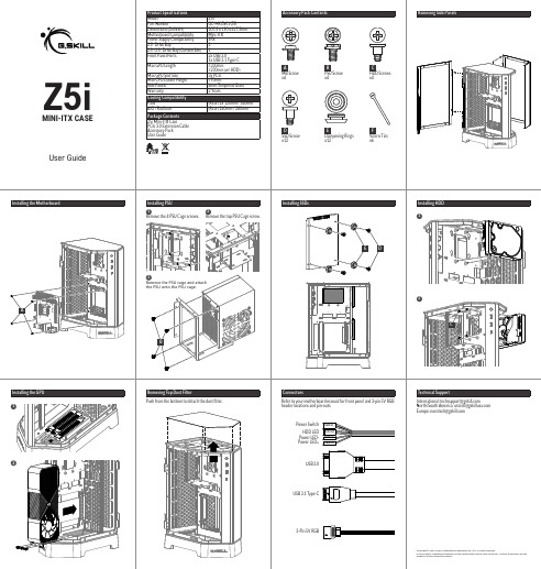
Z5i GC-MKGW1-Z5I 307.5 x 190 x 417.5mm Mini-ITX SFX 2 1 2x USB 3.0 1x USB 3.1 Type-C ≤330mm ≤230mm (w/ HDD) 3x PCIe 槽 ≤70mm 4mm 钢化玻璃 2年
POWER LEDPOWER LED+
USB 3.0
Technical Support
International: techsupport@ North/South America: ustech@ Europe: eurotech@
(后) 2x 120mm / 140mm (后) 240mm / 280mm
配件包内容
拆卸机箱侧板
A
主板螺丝 x4
B
电源螺丝 x4
C
机械硬盘螺丝 x4
D
固态硬盘螺丝 x12
E
固态硬盘防震垫 x12
F
扎线带 x6
安装电源
1 卸下电源支架 4 颗固定螺丝。
2 卸下电源支架上方的固定螺丝。
安装固态硬盘
3 取下电源支架,锁上电源后, 再安装回机箱上,固定好电源 支架的螺丝即可。
Connectors
Refer to your motherboard manual for front panel and 3-pin 5V RGB header locations and pin-outs.
Power Switch
HDD LED Power LEDPower LED+
POWER SW H.D.D LED
Z5i
- 1、下载文档前请自行甄别文档内容的完整性,平台不提供额外的编辑、内容补充、找答案等附加服务。
- 2、"仅部分预览"的文档,不可在线预览部分如存在完整性等问题,可反馈申请退款(可完整预览的文档不适用该条件!)。
- 3、如文档侵犯您的权益,请联系客服反馈,我们会尽快为您处理(人工客服工作时间:9:00-18:30)。
4. 1 个 MINI IDE 接口
5. 2 个 SATA 磁盘接口
6. 1 个 CPU 风扇接口
7. 1 个系统风扇接口
8. 1 组前置音频跳线插针
9. 3 个 USB 扩展插针接口
10. 1 组红外接口插针
11. 1 组 CMOS 清除跳线插针
12. 1 组 J3V 插针
13. 1 组 P12V 插针
--ITE8712F-S
--CPU 温度监控 --系统温度监控 --风扇转速监控 --各电压监控----可选
--1*4Mbit flash --提供中英文双语言 BIOS 界面
--ITX 170.00mm x 170.00mm
7
ITX-WN45AUP 正面图
8
ITX-WN45AUP 背板图
9
ITX-WN45AUP 主板规格表
2
目录
安全指导......................................................................2 商标声明...................................................................... 2 第一章 主板简介及规格说明............................................. 4
3
第一章 主板简介及规格说明
谢谢您采用了我司的 ITX 系列主板,为了保证产品品质并适合市场需 求,主板都通过了抗老化、低电压、各种温度、湿度环境下的反复测试, 均能满足行业的需求。是兼顾性价比、稳定、寿命长的高规格主流平台解 决方案,同时为了兼顾大部份海内外市场,我们专门提供了中英文两种语 言的 BIOS。本手册主要介绍了产品的规格参数及安装主板的步骤。需要更 加详细的主板 BIOS 设置信息可参看驱动光盘中的 BIOS 设置用户手册。
他部件. 10.不得将任何液体倒入机箱开口的缝隙中,否则会产生严重损坏或电路瘫痪. 11.如果发生以下情况,请找专业人员处理:
v 电源线或插头损坏 v 液体渗入机器内 v 机器暴露在潮湿的环境中 v 机器工作不正常或用户不能通过本手册的指导使其正常工作 v 机器跌落或受创 v 机器有明显的破损迹象
商标声明
1. 板载 Realtek ALC655 音效解码芯片 声卡
2. 支持2/4声道输出
网卡
1. 板载Realtek 8111C 双千兆网卡,支持10/100/1000M网络传输
存储标准
1. 2*SATA 3 Gb/s 磁盘接口 2. 1个44pin IDE磁盘接口
扩展槽
1. 1个PCI 插槽
USB
1. 支持7个USB 2.0 端口 (3个需要扩展)
14. 1 组 J5VSB 插针
15. 1 组 J5V 插针
16. 1 组 VGA_H 插针
17. 1 组 TV_OUT_H 插针
18. 1 个 COM 扩展插针
19. 4 组 JRI 插针
20. 1 组 LVDS 插针
21. 1 组 LVDS_PWR 插针
22. 1 组 INVERT 插针
23. 1 组前置面版插针
第三章 BIOS 简介..........................................................21
3.1 BIOS升级更新..............................................................................................21 3.2 BIOS设定.....................................................................................................21 3.3 BIOS语言切换..............................................................................................22
主机板支持 DDRII 内存,容量可从最小的 64MB 扩展至最大 2GB。 安装步骤如下: a. 将内存槽两端的白色卡榫向外扳开。 b. 将内存条有金手指的那边对准内存槽,注意内存条的凹孔要对应插槽
的凸起点。 c. 将内存条插入插槽中。若安装正确则插槽两端的白色卡榫会因为内存
条置入而自动卡紧,否则不会卡紧。
所有的品牌,产品,徽标,商标和公司名称都是属于商标或注册商标各自的拥 有者。
AMI® 是 AMI 公司的注册商标。 Intel® ,Celeron® ,Pentium® 是 Intel 公司的注册商标。 Netware® 是 Novell Inc.的注册商标。 PS/2 和 OS/2 是 International Business Machines 公司的注册商标。 Windows®98/ 2000/NT/XP 和 Microsoft® 是 Microsoft 公司的注册商 标。
后面板接口 I/O
1. 1个VGA 端口 2. 3个COM接口 3. 1个LPT接口 4. 4 个USB 2.0端口 5. 2 个RJ-45 网卡端口 1. ITE8712F-S双IO
10
内部输入/ 出 1. 1 个 24-pin ATX 主电源接口
接口
2. 1 个 DC 电源接口
3. 1 个 IDE_PWR 辅助电源接口
ITX 系列 用户手册
你现选用的产品型号为:
ITX-WN45A ITX-WN45AUP
Rev:1.0 Date:2009.1
1
安全指导
01. 务必请仔细通读本安全指导. 02. 务必请妥善保管本手册,以备将来参考. 03. 请保持本设备的干燥. 04. 机箱的开口缝隙是用于通风避免机箱内的部件过热,请勿将此类开口掩盖
由于主板规格和 BIOS 软件将不断更新,本手册之相关内容变 更恕不另行 通知,一切仅供参考,请以实际为准或留意网上公 布的升级版本.
1.1 包装盒内物品清单
v ITX-WN45A/WN45AUP 主板 v 80-Conductor Ultra ATA 66/100 IDE 数据线 v SATA 数据线 v 用户手册 -- 选配 v 驱动光盘 v 质保卡 v 合格证 v 挡板
1.2 主板 LAYOUT 图及规格表
ITX-WN45A
5 4
ITX-WN45A 主板规格如下表:
处理器 芯片组
内存
板上自带 Intel®AtomTM230/330 系列处理器
--北桥:Intel® 945GC --南桥:Intel® ICH7
--支持 DDRII533/667 内存. --最大容量支持 2GB --内存插槽 1*DDR2 DIMM
24. 1 组 PS/2 插针
1. CPU 温度监控
硬 件 监 测 功 2. 系统温度监控
能
3. 风扇转速监控
4. 各电压监控----可选
BIOS
1. 1*8Mbit flash
主板结构及 1. ITX 170.00mm x 170.00mm
尺寸
11
第二章 硬件设备的安装说明
2.1 内存的安装 2.1.1 DIMM 内存条的安装
第二章 硬件设备的安装说明.............................................12
2.1 内存的安装...................................................................................................12 2.2 主板跳线的设定说明.....................................................................................12 2.5 主机板接头说明.............................................................................................14
第四章 驱动程序的安装..................................................23
4. 1 芯片组驱动程序的安装...............................................................................23 4. 2 板载显卡驱动的安装...................................................................................23 4. 3 板载网卡驱动的安装...................................................................................23 4. 4 板载声卡驱动的安装...................................................................................23 4. 5 USB2. 0驱动程序的安装............................................................................23
处理器 芯片组
内存
1. 板上自带 Intel®AtomTMN270 系列处理器
1. 北桥:Intel®945GSE 2. 南桥:ICH7M
1. 支持DDRII533笔记本内存 2. 最大容量支持2GB 3. 内存插槽 1*DDR2 SODIMM
显卡