中国独角兽CEO的硅谷反思:这3个字,90%的中国企业都没做好
ceo岗位说明书
ceo岗位说明书一、岗位概述CEO(首席执行官)是公司最高级别的管理者,拥有决策权和领导权。
他/她负责制定和实施公司的战略目标和业务计划,监督并指导各部门的工作,确保公司运营高效、稳定发展。
二、岗位职责1. 定制战略目标:根据公司的使命和愿景,制定中长期战略目标,并确保其与公司业务发展的需要相匹配。
2. 领导团队:建立并领导高效的管理团队,指导各部门的工作,并定期组织公司管理层会议,促进信息沟通和协作。
3. 统筹运营管理:确保公司各项业务活动按照公司策略运行,并完善组织结构、流程和政策以提高运营效率。
4. 发展战略合作伙伴关系:寻找与公司业务战略相契合的战略合作伙伴,并建立、维护与其之间的合作关系。
5. 确保财务稳健:监督财务运营,与财务部门合作制定预算方案,并确保公司财务状况健康稳定。
6. 掌握市场趋势:保持对市场发展趋势、竞争对手动态、消费者需求变化的敏感度,为公司未来发展提供战略建议。
7. 代表公司形象:作为公司的形象代表出席各类公共活动,维护公司声誉。
三、任职资格1. 教育背景:本科及以上学历,管理类或相关专业。
2. 经验要求:具备丰富的企业管理经验,特别是在高级管理职位方面的经验。
3. 领导能力:卓越的领导才能,能够鼓舞员工、提升团队合作效率,并解决复杂问题。
4. 战略思维:具备推动公司发展的眼光和洞察力,能够制定战略目标并通过合理的执行计划实现。
5. 沟通技巧:出色的口头和书面沟通能力,能够与各级管理人员、员工和合作伙伴建立良好的关系。
6. 风险意识:敏锐的市场洞察力和危机应对能力,能够有效应对变化和风险。
7. 高度责任感:具备对公司利益高度关注和保护意识,能够权衡各方利益,并为员工创造有利的发展环境。
8. 领域专业知识:对所在行业和相关领域有深入了解和丰富的经验。
四、福利待遇公司将按照市场及个人能力提供具有竞争力的薪酬待遇,并提供完善的福利保障,包括但不限于社会保险、年度奖金、股权激励计划、健康体检、带薪年假等。
BOSS ME-90 吉他多效器说明书

Press ReleaseFOR IMMEDIATE RELEASEBOSS Announces ME-90 Guitar Multiple EffectsHands-On Guitar Processor with a Compact Design and Premium BOSS Amps and Effects Derived from the Flagship GT-1000Los Angeles, CA, July 6, 2023 announces the ME-90 Guitar Multiple Effects, afavorite of performing guitarists for over three decades, combining multi-effects power with hands-on control for crafting tones in seconds. The ME-90 is the most advanced ME model to date, offering exceptional audio quality with 24-bit AD/DA and 32-bit floating point processing, flagship-grade AIRD amp models, IR loading, an effects loop, and more. Compact, battery-powered, and filled with premium BOSS tones, this all-in-one processor makes it simple to build customized sound setups for every playing situation.With its intuitive interface and diverse effects selection, the ME-90 allows guitarists to create configurations and tweak tones with the ease of a stompbox-filled pedalboard. The panel includes 30 different knobs for selecting categories and dialing in sounds instantly. There are 36 preset patches with ready-to-play pro tones, plus 36 user patches for storing personalized setups.The ME-90 features a massive library of BOSS effects, offering seven different categories filled with selections derived from the flagship GT-1000. There are 60 effect types in total, with access to over 20 more via BOSS Tone Studio. A send/return loop is available for external pedals, complete with the ability to save the on/off status in patches and place the loop before or after amp models in the signal chain.Along with its effects, the ME-90 includes amp models ported from the GT-1000, driven by advanced AIRD technology for authentic tube tone and touch response. Eleven onboard amp types offer everything from clean combo tones to punishing high-gain stacks, and more selections are available in BOSS Tone Studio. Each amp includes a dedicated cab sound for connecting to a PA or recording device, and it’s also possible to load three user speaker IRs with a dedicated software app.The ME-90 features eight footswitches with smooth, quiet operation and an expression pedal with an integrated toe switch. Memory mode allows the player to call up complete patch setups with the footswitches, while Manual mode provides direct on/off control of each effect category within the patch. The footswitch LEDs light in different colors for quick identification in the heat of a performance. There’s also an option to set all LEDs to light in fixed colors for each mode if desired.BOSS Tone Studio for macOS and Windows allows users to organize patches, edit tones, and change out some amp and effect types with alternate selections. It’s also possible to download pro setups at BOSS Tone Central and swap patches with the ME-90 community on BOSS Tone Exchange. The ME-90 supports the optional Bluetooth® Audio MIDI Dual Adaptor, enablingusers to stream music from a mobile device and wirelessly shape tones using the dedicated BTS editor app for iOS and Android.The ME-90 is lighter than its previous generation model while maintaining the rock-solid durability that BOSS is famous for. The expression pedal has been newly redesigned as well for even finer parameter control. The processor can be powered with four AA batteries or an optional AC adaptor, and a rear-panel switch optimizes the outputs for use with a guitar amp or a full-range sound system such as a PA. And along with BOSS Tone Studio communication, the USB-C output provides audio interface functionality for working with music production software on a computer.Availability & PricingThe BOSS ME-90 is available in the U.S. now for $349.99. To learn more about the ME-90 Guitar Multiple Effects, visit /us/.*Price at the time of publishing.---------About BOSSBOSS, a division of Roland Corporation, has achieved legendary status among guitarists, bassists, and vocalists with a diverse, world-leading product lineup of creative tools with exceptional sound, intuitive control, and rugged durability. Since 1977, BOSS's famous compact pedals have been used daily by everyone from beginners to touring professionals, with over 125 unique models introduced and over 16 million units sold to date. BOSS also leads the way with innovative gear in numerous other categories, from amplifiers, multi-effects processors, and loopers to wireless systems, vocal effects, tuners, metronomes, rhythm machines, recorders, and more. For more information, visit . Follow BOSS on Facebook, Twitter (@BOSSInfoGlobal), and Instagram (@BOSSInfoGlobal).Press Contact:Sarah BellingerMax Borges Agency240-483-6671**********************************Company Contact:Rebecca GenelGlobal PR/Media Relations ManagerRoland Corporation+1 (323) 890-3718************************。
SSD2533

SOLOMON SYSTECHSEMICONDUCTOR TECHNICAL DATAThis document contains information on a product under development. Solomon Systech reserves the right to change or discontinue this product without notice. SSD2533 Rev 0.10 P 1/31 Oct 2010 Copyright © 2010 Solomon Systech LimitedSSD2533Product Preview23 Driving x 41 SensingCapacitive Touch Panel ControllerAppendix: IC Revision history of SSD2533 SpecificationVersion Change Items Effective Date 0.10 1st Release 26-Oct-10 Solomon Systech Oct 2010P 2/31 Rev 0.10 SSD2533CONTENTS1GENERAL DESCRIPTION (6)2FEATURES (6)3ORDERING INFORMATION (6)4BLOCK DIAGRAM (7)5PIN ARRANGEMENT (8)5.1100 PINS QFP (8)5.268 PINS QFN (9)5.348 PINS QFN (10)6PIN DESCRIPTIONS (11)6.1P OWER (11)6.2L OGIC (11)6.3A NALOG (12)6.4I NPUT AND O UTPUT (12)7FUNCTIONAL BLOCK DESCRIPTIONS (13)8COMMAND TABLE (13)9COMMAND DESCRIPTIONS (13)10REGISTERS (14)11MAXIMUM RATINGS (15)12DC CHARACTERISTICS (15)13AC CHARACTERISTICS (16)14POWER UP/DOWN SEQUENCE (18)14.1P OWER UP / DOWN FLOW CHART (18)14.2P OWER UP (19)14.3P OWER DOWN (20)15APPLICATION EXAMPLES (21)15.1A PPLICATION D IAGRAM (21)15.2P ANEL DESIGN REFERENCE (22)15.3FPC DESIGN REFERENCE (24)16PACKAGE INFORMATION (25)16.1QFP100 PINS (14X14MM) (25)16.2QFN68 PINS (8X8MM) (27)16.3QFN48 PINS (6X6MM) (28)16.4P ACKAGE ORIENTATION (29)SSD2533 Rev 0.10 P 3/31 Oct 2010Solomon SystechTABLEST ABLE 3-1:O RDERING I NFORMATION (6)T ABLE 5-1:100 PINS QFP P IN A SSIGNMENT T ABLE (8)T ABLE 5-2:68 PINS QFN P IN A SSIGNMENT T ABLE (9)T ABLE 5-3:48 PINS QFN P IN A SSIGNMENT T ABLE (10)T ABLE 11-1:M AXIMUM R ATINGS (V OLTAGE R EFERENCED TO V SS) (15)T ABLE 13-1:I2C I NTERFACE T IMING C HARACTERISTICS (16)T ABLE 13-2:S ERIAL T IMING C HARACTERISTICS (TA=-40 TO 85゚C,VDDIO=2.7V,VSS=0V) (17)T ABLE 15-1:5I NCH T OUCH P ANEL C HARACTERISTICS (23)T ABLE 15-2:7 TO 10I NCH T OUCH P ANEL C HARACTERISTICS (23)Solomon Systech Oct 2010P 4/31 Rev 0.10 SSD2533FIGURESF IGURE 4-1:SSD2533B LOCK D IAGRAM (7)F IGURE 5-1:P IN-OUT D IAGRAM –100 PINS QFP(T OP VIEW) (8)F IGURE 5-2:P IN-OUT D IAGRAM –68 PINS QFN(T OP VIEW) (9)F IGURE 5-3:P IN-OUT D IAGRAM –48 PINS QFN(T OP VIEW) (10)F IGURE 13-1:I2C INTERFACE T IMING CHARACTERISTICS (16)F IGURE 13-2:S ERIAL T IMING C HARACTERISTICS (17)F IGURE 15-1:A PPLICATION E XAMPLE (21)F IGURE 16-1:SSD2533QT2 PACKAGE ORIENTATION (29)F IGURE 16-2:SSD2533QN4 PACKAGE ORIENTATION (29)F IGURE 16-3:SSD2533QN5 PACKAGE ORIENTATION (30)SSD2533 Rev 0.10 P 5/31 Oct 2010Solomon Systech1GENERAL DESCRIPTIONSSD2533 is an all in one capacitive touch panel driver that integrated the power circuits, drivingand sensing circuits into a single MCU based chip. It can drive capacitive type touch panel withup to 23 driving and 41 sensing lines.2FEATURES•Operating voltage:o VCI: 2.5 ~ 3.3Vo VDDIO: 1.65 ~ 3.3V•6V to 9V(max.) driving voltage with external booster Caps•16 steps in 0.5V increment programmable driving voltage control•16 bit MCU core.•2K x 16 bit RAM for external ROM program.•16K x 16-bit Internal ROM•Support 2560x1408 touch resolution and capable to support up to Full-HD panel•Support 150Hz max. sampling rate (25 ~150Hz user programmable)•Total 23 driving and 41 sensing pins•Fully programmable driver scanning order•8 choices for Touch Screen Orientation control•Provide (X,Y) coordinates and number of touch points with force index and speed index• 4 independent capacitive sensing pins and 4 independent GPIO pins•Support up to 10 fingers•Automatic mode switching (Normal, Idle)•Auto calibration for each cross-over point•Support IIC (up to 400kbits/sec) and USB 1.1 interface•Package: QFN48, QFN68 and QFP1003ORDERING INFORMATIONTable 3-1: Ordering InformationOrdering Part Number Drive Sense Package Form MOQ / MPQ RemarkSSD2533QN5 1612 QFN48 TBD TBD SSD2533QN4 2112 QFN68 TBD TBD SSD2533QT2 2341 QFP100 TBD TBDSolomon Systech Oct 2010P 6/31 Rev 0.10 SSD25334BLOCK DIAGRAMFigure 4-1: SSD2533 Block DiagramSSD2533 Rev 0.10 P 7/31 Oct 2010Solomon Systech5 PIN ARRANGEMENT5.1100 pins QFPFigure 5-1: Pin-out Diagram – 100 pins QFP (Top view)Pin # Signal Name Pin # Signal Name Pin # Signal Name Pin # Signal Name1 AVSS 26 C3N 51 SENSE32 76 SENSE07SENSE0677SENSE312 /RESET 27 C3P 5278 SENSE05SENSE303 /IRQ 28 VOUT 5379 SENSE0429 VCHS 54SENSE294MASTER_SDA30 DRIVE00 55 SENSE28 80 SENSE035 MASTER_SCK6 SLAVE_SDA 31 DRIVE01 56 SENSE27 81 SENSE027 SLAVE_SCK 32 DRIVE02 57 SENSE26 82 SENSE018 STYPE0 33 DRIVE03 58 SENSE25 83 SENSE0084 AVSS9 STYPE1 34 DRIVE04 59 SENSE2410 KEY00 35 DRIVE05 60 SENSE23 85 VCI11 KEY01 36 DRIVE06 61 SENSE22 86 DRIVE2287 DRIVE2112 KEY02 37 DRIVE07 62 SENSE2188 DRIVE2013 KEY03 38 DRIVE08 63 SENSE2014 GPIO00 39 DRIVE09 64 SENSE19 89 DRIVE1915 GPIO01 40 DRIVE10 65 SENSE18 90 DRIVE1816 GPIO02 41 AVSS 66 SENSE17 91 DRIVE1717 GPIO03 42 VCI 67 SENSE16 92 DRIVE1693 DRIVE1518 DVSS 43 SENSE40 68SENSE1519 VCORE 44 SENSE39 69 SENSE14 94 DRIVE1420 VDDIO 45 SENSE38 70 SENSE1395 DRIVE1396SENSE12DRIVE1221 VCI 4671SENSE377297 DRIVE11SENSE11SENSE3622 BIAS 4798 VCHSSENSE1023 AVSS 48 SENSE35 7399 USB_DP74SENSE09SENSE3424 C2P 49100USB_DNSENSE0875SENSE3325 C2N 50Table 5-1 : 100 pins QFP Pin Assignment TableSolomon Systech Oct 2010P 8/31 Rev 0.10 SSD25335.268 pins QFNFigure 5-2: Pin-out Diagram – 68 pins QFN (Top view)Pin # Signal Name Pin # Signal Name Pin #Signal Name Pin #Signal Name1 /RESET 18 C3N 35 NC 52 AVSS2 /IRQ 19 C3P 36 NC 53 DRIVE223 MASTER_SDA 20 VOUT 37 NC 54 DRIVE214 MASTER_SCK 21 VCHS 38 SENSE20 55 DRIVE205 SLAVE_SDA 22 DRIVE00 39 SENSE19 56 DRIVE196 SLAVE_SCK 23 DRIVE01 40 SENSE18 57 DRIVE187 STYPE 24 DRIVE02 41 SENSE17 58 DRIVE178 GPIO003 25 DRIVE03 42 SENSE16 59 DRIVE169 DVSS 26 DRIVE04 43 SENSE15 60 DRIVE1510 VCORE 27 DRIVE05 44 SENSE14 61 DRIVE1411 VDDIO 28 DRIVE06 45 SENSE13 62 DRIVE1363SENSE12DRIVE1212 VCI 29DRIVE074613 BIAS 30 DRIVE08 47 SENSE11 64 DRIVE1114 AVSS 31 DRIVE09 48 SENSE10 65 VCHS15 C2P 32 DRIVE10 49 SENSE09 66 AVSS16 C2N 33 AVSS 50 NC 67 NC17 NC 34 NC 51 NC 68 NCTable 5-2 : 68 pins QFN Pin Assignment TableSSD2533 Rev 0.10 P 9/31 Oct 2010Solomon SystechSolomon SystechOct 2010P 10/31 Rev 0.10 SSD25335.3 48 pins QFNFigure 5-3: Pin-out Diagram – 48 pins QFN (Top view)Pin # Signal Name Pin # Signal Name Pin #Signal Name Pin #Signal Name 1 /RESET 13 C3N 25 SENSE20 37 AVSS 2 /IRQ 14 C3P 26 SENSE19 38DRIVE19 3 SLAVE_SDA 15 VOUT 27 SENSE18 39 DRIVE18 4 SLAVE_SCK 16 VCHS 28 SENSE17 40 DRIVE17 5 STYPE 17 DRIVE04 29 SENSE16 41 DRIVE16 6 DVSS 18 DRIVE05 30 SENSE15 42 DRIVE15 7 VCORE 19 DRIVE06 31 SENSE14 43 DRIVE14 8 VCI 20 DRIVE07 32 SENSE13 44 DRIVE13 9 BIAS 21 DRIVE08 33 SENSE12 45 DRIVE12 10 AVSS 22 DRIVE09 34 SENSE11 46 DRIVE11 11 C2P 23 DRIVE10 35 SENSE10 47 VCHS 12 C2N 24 AVSS 36 SENSE09 48 AVSSTable 5-3 : 48 pins QFN Pin Assignment Table6Key:PIN DESCRIPTIONSI = Input O =Output IO = Bi-directional (input/output) P = Power pin Hi-Z = High impedance6.1PowerPin Name VDDIO VCI VCHS DVSS AVSS Type P P P P P RESET# State N/A N/A N/A N/A N/A Description This pin is power supply input for I/O buffer This pin is power supply input for analog circuit This pin is ground for Booster and HV switches This pin is ground for logic This pin is ground for analog6.2LogicPin Name /RESET /IRQ SLAVE_ SDA SLAVE_ SCK MASTER _SDA MASTER _SCK STYPE0, STYPE1, GPIO3 USB_DP USB_DN Type I O IO I IO I I IO IO RESET# State VDDIO VDDIO Hi-Z Hi-Z Hi-Z Hi-Z Hi-Z Hi-Z Hi-Z Description This is Reset pin for the chip This is Interrupt pin for Interrupt request IIC data pin IIC clock input pin IIC data pin in MCU mode IIC clock input pin in MCU mode Bus interface mode selection pin. USB data+ pin USB data- pinSSD2533Rev 0.10P 11/31Oct 2010Solomon Systech6.3AnalogPin Name C2P C2N C3P C3N VOUTBIASType IO IO IO IO P P PRESET# State VCI/VCHS VCI/VCHS VCI/VCHS VCI/VCHS VCI/VCHS VCI/VCHS N/ADescription Booster pin. Connect a capacitor to C2N Booster pin. Connect a capacitor to C2P Booster pin. Connect a capacitor to C3N Booster pin. Connect a capacitor to C3P Output power supply for booster. Connect a capacitor for stabilization Regulated voltage supply for sensor circuit. Connect a capacitor for stabilization Regulated voltage supply for logic circuit. Connect a capacitor for stabilizationVCORE6.4Input and OutputPin Name SENSE00 – SENSE40 DRIVE00 – DRIVE22 KEY00 – KEY03 GPIO00 – GPIO03 Type I O I I RESET# State Hi-Z VCHS Hi-Z Hi-Z Description Sensor input pins Driver output pins Self-cap input pins GPIO pinsSolomon SystechOct 2010 P 12/31Rev 0.10SSD25337TBDFUNCTIONAL BLOCK DESCRIPTIONS8TBDCOMMAND TABLE9TBDCOMMAND DESCRIPTIONSSSD2533Rev 0.10P 13/31Oct 2010Solomon Systech10 REGISTERSVDDIO = VCI = 2.775V 1.) Hardware Reset 2.) Set the number of driver line. 3.) Set the number of sense line. 4.) Set the driver line scanning order. 5.) Turn on the booster circuit and set the VOUT to ~7.5V.Hardware ResetSet the number of driver lineSet the number of sense lineSet the driver line scanning orderTurn on the booster circuit and set the VOUT to ~7.5VSolomon SystechOct 2010 P 14/31Rev 0.10SSD253311 MAXIMUM RATINGSTable 11-1: Maximum Ratings (Voltage Referenced to VSS) Parameter Value Supply Voltage for Logic -0.3 to +2.0 Supply Voltage for I/O -0.3 to +4.0 Input Voltage VSS -0.3 to +5.0 Current Drain Per Pin Excluding VCORE and VSS 25 Operating Temperature -40 to +85 Storage Temperature -65 to +150Symbol VCORE VDDIO VCI I TA TSTGUnit V V V mA o C o CMaximum ratings are those values beyond which damages to the device may occur. Functional operation should be restricted to the limits in the Electrical Characteristics tables or Pin Description section This device contains circuitry to protect the inputs against damage due to high static voltages or electric fields; however, it is advised that normal precautions be taken to avoid application of any voltage higher than maximum rated voltages to this high impedance circuit. For proper operation it is recommended that VCI and VOUT be constrained to the range VSS < VDD ≤ VCI < VOUT. Reliability of operation is enhanced if unused input is connected to an appropriate logic voltage level (e.g., either VSS or VDD). Unused outputs must be left open. This device may be light sensitive. Caution should be taken to avoid exposure of this device to any light source during normal operation. This device is not radiation protected.12 DC CHARACTERISTICSDC Characteristics (Unless otherwise specified, Voltage Referenced to VSS, TA = -40 to 85oC)Symbol Parameter VDDIO VCI Isleep1 Isleep2 Idp VOUT VOH1 VOL1 VIH1 VIL1 IOH IOL IOZ IIL/IIH Note1: Power supply pin of I/O pins Booster Reference Supply Voltage Range (3) Sleep mode current (VCI pin) Sleep mode current (VDDIO pin) Operating mode current VOUT booster efficiency1 Logic High Output Voltage Logic Low Output Voltage Logic High Input voltage Logic Low Input voltage Logic High Output Current Source Logic Low Output Current Drain Logic Output Tri-state Current Drain Source Logic Input Current Conditions Recommend Operating Voltage Possible Operating Voltage Recommend Operating Voltage Possible Operating Voltage VDDIO=1.8V, VCI=2.8V 100pF loading at Source output VDDEXT=VDDIO=1.8V, VCI=3.3V IDP = IVDDIO + IVDDEXT + IVCI See Note1 Iout=-100uA Iout=100uA Min 1.65 2.5 or VDDIO 70 0.9 * VDDIO 0 0.8 * VDDIO 0 50 -1 -1 Typ TBD TBD TBD 85 Max 3.3 3.3 TBD TBD TBD VDDIO 0.1 * VDDIO VDDIO 0.2 * VDDIO -50 1 1 Unit VVuA uA mA % V V V V μA μA μA μAVOH = VDDIO-0.4V VOL = 0.4VVOUT efficiency = VOUT /(2 x VCI) x 100%SSD2533Rev 0.10P 15/31Oct 2010Solomon Systech13 AC CHARACTERISTICSConditions: VDD - VSS = 2.4 to 3.5V VDDIO = VDD TA = 25°CTable 13-1 :I C Interface Timing Characteristics2Symbol tcycle tHSTART tHD tSD tSSTART tSSTOP tR tF tIDLEParameter Clock Cycle Time Start condition Hold Time Data Hold Time (for “SDA” pin) Data Setup Time Start condition Setup Time (Only relevant for a repeated Start condition) Stop condition Setup Time Rise Time for data and clock pin Fall Time for data and clock pin Idle Time before a new transmission can startMin 2.5 0.6 0 100 0.6 0.6 1.3Typ -Max 300 300 -Unit us us ns ns us us ns ns usFigure 13-1 : I C interface Timing characteristicsSDA 0.8VDDIO 0.2VDDIO2////tIDLEtHD tHSTARTSCL 0.8VDDIO 0.2VDDIOtF tSDtRtSSTARTtSSTOPtCYCLESolomon SystechOct 2010 P 16/31Rev 0.10SSD2533Table 13-2 : Serial Timing Characteristics (TA = -40 to 85 ゚ C, VDDIO = 2.7V, VSS =0V)Symbol Parameter Clock Cycle Time Address Setup Time Address Hold Time Chip Select Setup Time Chip Select Hold Time Write Data Setup Time Write Data Hold Time Clock Low Time Clock High Time Rise Time Fall Time Min 58.8 10 5 30 29.4 30 30 29.4 29.4 Typ Max 15 15 Unit ns ns ns ns ns ns ns ns ns ns nstcycle tAS tAH tCSS tCSH tDSW tOHW tCLKL tCLKH tR tFD/C (Required if PS1 = H)0.8VDDIO 0.2VDDIOtAS tAH tCS H t c ycle tC L KHCStCSS0.2VDDIOtC LK L SCK tF tDSW SDA Valid DatatR0.8VDDIO 0.2VDDIOtDHW0.8VDDIO 0.2VDDIOCSSCKSDAD7D6D5D4D3D2D1D0Figure 13-2 : Serial Timing CharacteristicsSSD2533Rev 0.10P 17/31Oct 2010Solomon Systech14Power up/down Sequence14.1 Power up / down flow chartThe figures below illustrate a flow chart and timing diagram for power up/down sequence of the driver.Power Supply VCI = 2.5V ~ 3.3V VDDIO = 1.65V ~ VVCIHardware Reset Active low ≥10uSTurn on LCD panelInitialization init code (refer to software setup ) - Need 300ms to stabilizeNormal Operation ModeEntering Power Saving Powering offPower Saving Mode- Automatic entered after a period of time without touch. - Turn off LCD display -Power OffTurn off booster Delay 50ms Idle Mode Enable sleep Mode Discharge VOUT at least <4V - Power off VCI and VDDIO suppliesReturning to Normal Mode- Turn on LCD display - init code (refer to software setup )Note:To prevent potential damage to the device, all capacitors must be discharged to below 0.5V before the driver is removed from, or before the driver is attached to those components.Solomon SystechOct 2010 P 18/31Rev 0.10SSD253314.2 Power upSymbol tPR tPD tSTABLE tRES tREADYParameter Power rise time Power delay time Chip stable time Reset pulse Chip need time after hardware resetMin 4 -Typ -Max 30 30 10 1Unit us us us us ustPR VCI CS tPD VDDIO tSTABLE RES tREADY SDA, SCL tRESSSD2533Rev 0.10P 19/31Oct 2010Solomon Systech14.3 Power downSymbol tDISCHARGE tPDOWNParameter VOUT discharge wait time Power Hold timeMin 50 50Typ -Max -Unit ms msVOUT.TDISCHARGEVCI/VDDIORES tPHOLDSDA, SCL Power off Enter power save mode•With regards to the Power Off, Vout should be discharged at least below than 5V before turn off the VCI/VDDIO power suppliesSolomon SystechOct 2010 P 20/31Rev 0.10SSD253315APPLICATION EXAMPLES 15.1Application DiagramFigure 15-1: Application Example23 pins driving Signals 7.5V max1~2.2uF/6.3V1~2.2uF/16V15.2 Panel design referenceTable 15-1 : 5 Inch Touch Panel CharacteristicsUnitMax Symbol Parameter Min TypRdrive Drive line resistance - 4 6 kΩRsense Sense line resistance - 4 6 kΩPitch Touch pattern pitch 3 - 6 mmGw Pattern Gap width 0.3 0.5 1 mmISO Isolation Glass thickness - - 0.6 mmLens 0.4 0.5 1 mmProtectiveFPL FrontTable 15-2 : 7 to 10 Inch Touch Panel CharacteristicsUnitMax Symbol Parameter Min TypRdrive Drive line resistance - 20 TBDkΩRsense Sense line resistance - 20 TBDkΩPitch Touch pattern pitch 3 - 6 mmGw Pattern Gap width 0.3 0.5 1 mmISO Isolation Glass thickness - - 0.6 mmProtectiveLens 0.4 0.5 1 mmFPL Front•Drive line resistance and Sense line resistance included the Diamond pattern, routing trace, FPC and package resistance.•Metal coating is recommended for the ITO trace.•GND line is recommended to insert between the drive and sense line.15.3 FPC design reference• GND line is recommended to insert between the drive and sense line. • The DRIVE line should not cross over the SENSE line.G N DU S B _D P U S B _D N G N D /R E S E T /I R Q M A S T E R _S D A M A S T E R _S C K S L A V E _S D A S L A V E _S C K S T Y P E 0 S T Y P E 1 K E Y 00 K E Y 01 K E Y 02 K E Y 03 G P I O 00 G P I O 01 G P I O 02 G P I O 03 G N D G N D V D D I O V C I G N DDRIVE11…DRIVE22 GND SENSE00…SENSE40 GND DRIVE10…DRIVE0016PACKAGE INFORMATION 16.1QFP 100 pins (14x14mm)SYMBOL MIN NOM MAXTOTAL THICKNESS A --- --- 1.2STAND OFF A1 0.05 --- 0.15MOLD THICKNESS A2 0.95 --- 1.05WIDTH(PLATING) b 0.17 0.22 0.27LEADWIDTH b1 0.17 0.2 0.23LEADBSCX D 16BSCY E 16BODY SIZE X D1 14 BSCY E1 14 BSCLEAD PITCH e 0.5 BSCL 0.45 0.6 0.751REF FOOTPRINT L1θ0o 3.5o7oθ1 0o --- ---θ2 11o 12o 13oθ3 11o 12o 13oR1 0.08 --- ---R2 0.08 ---S 0.2 --- ---PACKAGE EDGE TOLERANCE aaa 0.2LEAD EDGE TOLERANCE bbb 0.2COPLANARITY ccc0.08 LEAD OFFSET ddd 0.08MOLD FLATNESS eee 0.0516.2QFN 68 pins (8x8mm)SYMBOL MIN NOM MAXTHICKNESS A 0.8 0.85 0.9 TOTALSTAND OFF A1 0 0.035 0.05MOLD THICKNESS A2 --- 0.65 0.67L/F THICKNESS A3 0.203 REFWIDTH b 0.15 0.20 0.25LEADBODY SIZE X D 8 BSCY E 8 BSCLEAD PITCH e 0.4 BSCSIZE X J 6.1 6.2 6.3 EPY K 6.1 6.2 6.3LENGTH L 0.35 0.4 0.45 LEADPACKAGE EDGE TOLERANCE aaa 0.1MOLD FLATNESS bbb 0.1COPLANARITY ccc 0.08LEAD OFFSET ddd 0.1EXPOSED PAD OFFSET eee 0.116.3QFN 48 pins (6x6mm)SYMBOL MIN NOM MAXTHICKNESS A 0.8 0.85 0.9TOTALSTAND OFF A1 0 0.035 0.05MOLD THICKNESS A2 --- 0.65 0.67L/F THICKNESS A3 0.203 REFWIDTH b 0.15 0.2 0.25LEADBODY SIZE X D 6 BSCY E6BSCLEAD PITCH e 0.4 BSCSIZE X J 4.1 4.2 4.3EPY K 4.1 4.2 4.3LENGTH L 0.35 0.4 0.45LEADPACKAGE EDGE TOLERANCE aaa 0.1MOLD FLATNESS bbb 0.10.08COPLANARITY cccLEAD OFFSET ddd 0.1EXPOSED PAD OFFSET eee 0.116.4Package orientationFigure 16-1 : SSD2533QT2 package orientationFigure 16-2 : SSD2533QN4 package orientationFigure 16-3 : SSD2533QN5 package orientationSolomon Systech reserves the right to make changes without notice to any products herein. Solomon Systech makes nowarranty, representation or guarantee regarding the suitability of its products for any particular purpose, nor does SolomonSystech assume any liability arising out of the application or use of any product or circuit, and specifically disclaims any, andall, liability, including without limitation consequential or incidental damages. “Typical” parameters can and do vary indifferent applications. All operating parameters, including “Typical” must be validated for each customer application by thecustomer’s technical experts. Solomon Systech does not convey any license under its patent rights nor the rights of others.Solomon Systech products are not designed, intended, or authorized for use as components in systems intended for surgicalimplant into the body, or other applications intended to support or sustain life, or for any other application in which the failureof the Solomon Systech product could create a situation where personal injury or death may occur. Should Buyer purchase oruse Solomon Systech products for any such unintended or unauthorized application, Buyer shall indemnify and hold SolomonSystech and its offices, employees, subsidiaries, affiliates, and distributors harmless against all claims, costs, damages, andexpenses, and reasonable attorney fees arising out of, directly or indirectly, any claim of personal injury or death associatedwith such unintended or unauthorized use, even if such claim alleges that Solomon Systech was negligent regarding the designor manufacture of the part.The product(s) listed in this datasheet comply with Directive 2002/95/EC of the European Parliament and of the council of27 January 2004 on the restriction of the use of certain hazardous substances in electrical and electronic equipment andPeople’s Republic of China Electronic Industry Standard SJ/T 11363-2006 “Requirements for concentration limits for certainhazardous substances in electronic information products (电子信息产品中有毒有害物质的限量要求)”. Hazardous Substancestest report is available upon request.SSD2533 Rev 0.10 P 31/31 Oct 2010Solomon Systech。
Lincoln Helix M85 Weld Head 用户操作手册说明书

Operator’s ManualRegister your machine:/registerAuthorized Service and Distributor Locator: /locatorIM6126 | Issue D a te 11/18© Lincoln Global, Inc. All Rights Reserved.For use with machines having Code Numbers:70315, 12735Need Help? Call 1.888.935.3877 to talk to a Service Representative Hours of Operation:8:00 AM to 6:00 PM (ET) Mon. thru Fri.After hours?Use “Ask the Experts” at A Lincoln Service Representative will contact you no later than the following business day. For Service outside the USA:Email:*********************************Save for future referenceDate PurchasedCode: (ex: 12735)Serial: (ex: U1060512345)SECTION A:WARNINGS CALIFORNIA PROPOSITION 65 WARNINGSWARNING: This product, when used for welding orcutting, produces fumes or gases which containchemicals known to the State of California to causebirth defects and, in some cases, cancer. (CaliforniaHealth & Safety Code § 25249.5 et seq.)ARC WELDING CAN BE HAZARDOUS. PROTECTYOURSELF AND OTHERS FROM POSSIBLE SERIOUSINJURY OR DEATH. KEEP CHILDREN AWAY.PACEMAKER WEARERS SHOULD CONSULT WITHTHEIR DOCTOR BEFORE OPERATING.Read and understand the following safety highlights. Foradditional safety information, it is strongly recommendedthat you purchase a copy of “Safety in Welding & Cutting -ANSI Standard Z49.1” from the American Welding Society,P.O. Box 351040, Miami, Florida 33135 or CSA StandardW117.2-1974. A Free copy of “Arc Welding Safety” bookletE205 is available from the Lincoln Electric Company,22801 St. Clair Avenue, Cleveland, Ohio 44117-1199.BE SURE THAT ALL INSTALLATION, OPERATION,MAINTENANCE AND REPAIR PROCEDURES AREPERFORMED ONLY BY QUALIFIED INDIVIDUALS.FOR ENGINE POWEREDEQUIPMENT.1.a.Turn the engine off before troubleshootingand maintenance work unless themaintenance work requires it to be running.1.b.Operate engines in open, well-ventilated areas or vent the engineexhaust fumes outdoors.1.c.Do not add the fuel near an open flame weldingarc or when the engine is running. Stop theengine and allow it to cool before refueling toprevent spilled fuel from vaporizing on contactwith hot engine parts and igniting. Do not spill fuel when fillingtank. If fuel is spilled, wipe it up and do not start engine untilfumes have been eliminated.1.d. Keep all equipment safety guards, coversand devices in position and in good repair.Keep hands, hair, clothing and tools awayfrom V-belts, gears, fans and all othermoving parts when starting, operating orrepairing equipment.1.e.In some cases it may be necessary to remove safety guards toperform required maintenance. Remove guards only whennecessary and replace them when the maintenance requiringtheir removal is complete. Always use the greatest care whenworking near moving parts.1.f. Do not put your hands near the engine fan. Do not attempt tooverride the governor or idler by pushing on the throttle controlrods while the engine is running.1.g.To prevent accidentally starting gasoline engines while turningthe engine or welding generator during maintenance work,disconnect the spark plug wires, distributor cap or magneto wireas appropriate.1.h.To avoid scalding, do not remove the radiatorpressure cap when the engine is hot.2.a.Electric current flowing through any conductorcauses localized Electric and Magnetic Fields (EMF).Welding current creates EMF fields around welding cablesand welding machines2.b.EMF fields may interfere with some pacemakers, andwelders having a pacemaker should consult their physicianbefore welding.2.c.Exposure to EMF fields in welding may have other health effectswhich are now not known.2.d.All welders should use the following procedures in order tominimize exposure to EMF fields from the welding circuit:2.d.1.Route the electrode and work cables together - Securethem with tape when possible.2.d.2.Never coil the electrode lead around your body.2.d.3.Do not place your body between the electrode and workcables. If the electrode cable is on your right side, thework cable should also be on your right side.2.d.4.Connect the work cable to the workpiece as close as pos-sible to the area being welded.2.d.5.Do not work next to welding power source.HELIX® M85 WELD HEADTABLE OF CONTENTSTechnical Specifications HELIX M85 WELD HEAD ................................................................................A-1 Safety Precautions ...................................................................................................................................A-2 Proper handling .....................................................................................................................................A-2 Operation ...............................................................................................................................................A-2 HELIX M85 WELD HEAD ...........................................................................................................................A-3 Basic Information ...................................................................................................................................A-3 Basic Components ................................................................................................................................A-3 Body Assembly ......................................................................................................................................A-3 Torch Motion Assembly .........................................................................................................................A-3 Torch Assembly .....................................................................................................................................A-4 Torch Consumables ...............................................................................................................................A-5 Tracks ....................................................................................................................................................A-6 Track Ring Installation ..........................................................................................................................A-7 Flat Track Installation ............................................................................................................................A-8 Weld Head Installation ..........................................................................................................................A-8 Weld Head Positioning ..........................................................................................................................A-8 Weld Head Setup ..................................................................................................................................A-8 Torch Placement ....................................................................................................................................A-8 Latch Tension ........................................................................................................................................A-9 Clamp Latch Adjustment .....................................................................................................................A-10 Checking Clutch Latch Tension ...........................................................................................................A-10 Clutch Latch Tension Adjustment .........................................................................................................A-11 Operational Safety Precautions ...............................................................................................................B-1 Operation Information ............................................................................................................................B-1 External inputs ......................................................................................................................................B-1 Control ...................................................................................................................................................B-1 Welding Power ......................................................................................................................................B-1 Manual Adjustments ..............................................................................................................................B-1 Accessories ...............................................................................................................................................C-1 Torch Accessories .................................................................................................................................C-1 Maintenance...............................................................................................................................................D-1 Maintenance Schedule ..........................................................................................................................D-1 Every Shift .......................................................................................................................................D-1 Monthly ............................................................................................................................................D-1 Semi Annually .................................................................................................................................D-1 Tools ................................................................................................................................................D-1 Trouble Shooting ........................................................................................................................................F-1 Wiring Diagram ..........................................................................................................................................G-1 Dimensions Diagram.................................................................................................................................G-2 Helix M85 Parts Manual.............................................................................................................................P-1Technical Specifications HELIX M85 Weld HeadExplanation of SymbolsElectric Shock WarningLiner InstallationInstallation of KP45 - [ ]a. Lay the gun and cable straight on a flat surface.b.M ake sure that the set screw in the connector end is backed out so as not to damage the liner or the liner bushing. Remove and save the gas nozzle, nozzle bushing and gas diffuser from the end of the gun assembly.c.I nsert a new untrimmed liner into the connector end of the cable. Be sure the liner bushing is stenciled appropriately for the wire size being used.d. Tighten the set screw.e.B e sure the cable is straight. Trim the liner to a length of approximately 9/16” (14.3 mm) past the coupler. Remove any burrs from the end of the liner.f.S crew the gas diffuser onto the end of the coupler and tighten.g. Replace the nozzle bushing and gas nozzle. CONTACT TIP AND GAS NOZZLE INSTALLATION a.C hoose the correct size contact tip for the electrode being used (wire size is stenciled on the side of the contact tip) and screw it snugly into the gas diffuser.b.I nstall the appropriate gas nozzle onto the diffuser. The proper nozzle should be selected based on the welding application. Choose the gas nozzle as ap-propriate for the process to be used. Typically, the contact tip end should be flush to 1/8" (3.2 mm) ex-tended for the short-circuiting transfer process for all three and .12" (3.1mm) recessed for spray transfer. For the FCAW-G process, 1/8" (3.2 mm) recess is recommended.CONNECTION TO FEEDERa.C heck that the drive roll(s) and the feeder guide plate is appropriate for the electrode size being used.b.F ully push the brass connector end of the gun cable into the conductor block on the outgoing side of the feeder wire drive. Secure the cable using the hand screw or set screw in the conductor block. AVOIDING WIRE FEEDING PROBLEMSWire feeding problems can be avoided by observing the following gun handling procedures: a. Do not kink or pull cable around sharp corners.b.K eep the electrode cable as straight as possible when welding or loading electrode through cable.c.A void wrapping excess cable around handle or front of wire feeder especially on longer 20 and 25 ft (6.1 and 7.6 m) length guns.d.D o not allow dolly wheels or trucks to run over cables.e.K eep cable clean by following maintenance instructions.f.U se only clean, rust-free electrodes. To better ensure proper surface lubrication, we recommend using only Lincoln Electric brand electrodes.g.R eplace contact tip when the arc starts to become unstable or the contact tip end is fused or deformed. IMPORTANT!a. Replace worn contact tips as required.b. R emove spatter from inside of gas nozzle and from tip after each 10 minutes of arc time or as required.GUN CABLESCABLE CLEANINGClean cable liner after using approximately 300 pounds (136 kg) of electrodes. Remove the cable from the wire feeder and lay it out straight on the floor. Remove the contact tip from the gun. Using an air hose and only partial pressure, gently blow out the cable liner from the gas diffuser end.Excessive pressure at the start may cause the dirt to form a plug.Flex the cable over its entire length and again blow out the cable. Repeat this procedure until no further dirt comes out.hen loosen the secondary set screw on the under-side of the HELIX M85,see Figure 20 - Secondary Clamp Set Screw.Turn the adjustment screw clockwise to increase the tension. Turning it counterclockwise will decrease the est the tension by placing the weld head back on the track.nce the desired tension is achieved, tighten the set screws to lock it in. Be sure not to over tighten the set screws.Checking Clutch Latch TensionIf the clutch latch is too tight it will not be able to rideSET SCREWFIGURE 19 - Latch Set ScrewSECONDARYSET SCREWADJUSTMENT SCREW FIGURE 21 - Adjustment ScrewADJUSTMENT SCREWFIGURE 23 - Adjustment ScrewHELIX® M85 WELD HEADACCESSORIESMAINTENANCE HELIX® M85 WELD HEADMaintenanceThe HELIX M85 weld head is designed for trouble-free operation and normally requires minimal preventive care and cleaning. This section provides instructions for maintaining user-serviceable items. The suggested repair procedure for all such items is to remove and replace defective assemblies or parts.When users and/or service personnel are not familiar with electrical and electronic equipment, the product should be returned to the factory or serviced by factory authorized representatives.Maintenance ScheduleThe maintenance schedule is suggested as a guideline for proper system maintenance. More stringent main-tenance requirements may be required depending on the work being performed and the requirements of the customer for whom the work is performed. All mainte-nance schedules are based on a 40-hour work week. Any excess play in parts or equipment should be noted and reported to an authorized repair facility. Any anomalous activity, such as motor hesitation, clicking or other noises, or anything out of the ordinary should be noted and reported to an authorized repair facility. Every Shift• Check lines, cables, and drive belts for loose con-nections and worn areas.• Change out consumables as needed.• Check torch height motion and travel for slop or wearing parts.N OTE: Do not force the oscillator in or out while checking for worn parts.• Inspect torch cable for wear or damage.Monthly• Apply a type of high temperature lubricant oranti-spatter spray to the bellows every 30 daysor as needed.• With the clutch latch and clamp latch engaged, grab the weld head by the handles and gently move back and forth to check for excess play in the weld head along the track.• Release the clutch latch and verify that the weld head moves smoothly along the track without rub-bing or binding.• Examine all cable connections to verify that there are no gas leaks, and that all cables are seated correctly and that there is no visible wear and tear to any con-nector or associated cables. • Check over the all weld head components for any signs of damage or wearing.• Ensure track ring gears and weld head gears are clean and clear of debris.• Check for wear of drive rolls on wire feeder.Semi Annually• Based on a 40-hour work week it is recommended that the belts be replaced every six months.• Verify that all motors are working correctly without strain. Listen to the motors to confirm that there is no excess noise or grinding.ToolsRequired tools to operate and repair the HELIX M85 weld head:• 2.5 mm hex key• 3 mm hex key• 4 mm hex key• 6 mm hex key• wire cutters• flat-head screwdriverFurther tools are required for in depth maintenance which is only authorized at local repair facilities.M85 WELD HEADHELIX®TROUBLE SHOOTINGObserve all Safety Guidelines detailed throughout this manual.HELIX® M85 WELD HEADTROUBLE SHOOTING Observe all Safety Guidelines detailed throughout this manual.P-788Weld Head Side Panels9-30-18Use only the parts marked “x” in the column under the heading number called for in the model index page.# Indicates a change in this printing.P-788Weld Head Side PanelsP-788Weld Head Torch Motion9-30-189-30-18Use only the parts marked “x” in the column under the heading number called for in the model index page.# Indicates a change in this printing.P-788Weld Head Torch MotionITEM DESCRIPTION PART NO.QTY.123456789Weld Head Torch Motion1Torch Stop9SM245561x 2Bellows Retainer 9SM245612x 33A 3B Torch Clamp Assy Torch Clamp (NSS) Washer (NSS)9SM24562112x x x 4Torch Mount Assy 9SM245661x 55A 5B Shaft Assy Shafts (NSS)Screws (not shown) (NSS)9SS30339124x x x 6Up Down Adjustment Handle 9SS305011x 7Lead Lag Adjustment Handle 9SS305031x 88A 8B Spatter Shield Assembly Spatter Shield (NSS) Screw (NSS)KP52112-11111x x x 9Oscillation Cover Kit (2 per kit)KP52135-11x 10Inner CoverKP52138-11x 11Torch Pivot AssyKP52139-11x 12Weld Angle Adjustment Handle9SS305021xP-788Weld Head Clamping Assemlby9-30-189-30-18Use only the parts marked “x” in the column under the heading number called for in the model index page.# Indicates a change in this printing.P-788Weld Head Clamping AssemblyITEM DESCRIPTION PART NO.QTY.123456789Weld Head Clamping Assembly1Roller Pivots9SM229494x 22A 2B Outer Cover Assy Outer Cover (NFS) Screw (NFS) 9SM24378116x x x 3Outboard Plate 9SM245581x 44A 4B 4C 4D 4E 4F Clamp Lever Assy Washer (NFS) Shaft (NFS) Cam Nut (NFS)Spring Washer (NFS) Set Screw (NFS) Clamp Lever9SS30726-19SM244191111411x x x x x x x 55A 5B 5C 5D 5ECable Retainer Clamp Assy Retainer Base (NFS) Retaining Screw (NFS) Washer (NFS)Retainer Top (NFS) Screw (NFS)9SS30726-4111112x x x x x xP-788Weld Head Top Panel9-30-189-30-18Use only the parts marked “x” in the column under the heading number called for in the model index page.# Indicates a change in this printing.P-788Weld Head Top PanelITEM DESCRIPTION PART NO.QTY.123456789M85 Weld Head Top Panel11A 1B M85 Top Cover Kit Top Cover (NFS) Screw (NFS)9SM24540115x x x 22A 2B 2C 2D 2E 2FClutch Lever Assy Cam Nut (NFS) Shaft (NFS)300 lb Spring (NFS) 5 lb Spring (NFS) Screw (NFS) Clutch Lever9SS30726-29SS296991111111x x x x x x xP-788Weld Head Internal Assembly9-30-189-30-18Use only the parts marked “x” in the column under the heading number called for in the model index page.# Indicates a change in this printing.P-788Weld Head Internal AssemblyITEM DESCRIPTION PART NO.QTY.123456789M85 Weld Head Internal1Tractor Input Harness 9SM230431x x 2Idler9SM245411x x 33Transmission Transmission9SM245509SM2356011x ••x 44A 4B Inboard Side Plate Assy Inboard Side Plate (NFS)Socket Head Cap Screw (NFS)9SM245881110x x x x x x 55A 5B 3/8 Linear Bearing Kit3/8 Linear Bearing (NFS) Retaining Clip (NFS)9SS28985444x x x x x x 6Compression Spring9SS290452x x 71/2 Flanged Linear Bearing 9SS299882x x 8Oscillator Ball Screw Assy 9SS299901x x 9Torch Height Screw9SS299911x x 1010A 10B Torch Height Motor Assy Torch Height MotorScrews (NFS) (Not Pictured)9SS30308-1113x x x x x x 1111A 11B Torch Height Controller Assy Torch Height Controller (NFS) Screws (NFS)9SM23204-2113x x x x x x 121212A 12B Travel Controller Assy Travel Controller Assy Travel Controller (NFS) Screw (NFS)9SM23203-19SM23203-21113x •x x •x x x 1313A 13B Oscillator Motor Assembly Oscillator Motor (NFS) Screw (NFS)9SS30496-1116x x x x x x 146mm Pulley Assembly 9SS305241x x 154mm Pulley Assembly 9SS305251x x 16Torch Height Belt KP52136-11x x 17Oscillator BeltKP52137-11x x 18Low Profile Shoulder Screw 9SS305051x x 1919A 19BOscillation Controller Assembly Oscillation Controller (NFS) Screw (NFS)9SM23204-1113x x xx x xP-788Mechanized Torch9-30-189-30-18Use only the parts marked “x” in the column under the heading number called for in the model index page.# Indicates a change in this printing.P-788Mechanized TorchITEM DESCRIPTION PART NO.QTY.123456789Mechanized Torch1Magnum Pro Torch Assembly 550A 25’ 550A 15’K52106-25K52106-151x x 2Torch Body Half 9SM23331-0552x 3Nozzle Bushing KP52144-11x 4Gas DiffuserKP2747-11x 5Magnum Pro Contact Tip Contact Tip 0.035” (0.9mm) Contact Tip 0.040” (0.9mm) Contact Tip 0.045” (0.9mm) Contact Tip 0.052” (0.9mm) Contact Tip 1/16” (0.9mm)KP2745-035R KP2745-040R KP2745-045R KP2745-052R KP2745-116R 1x x x x x 6Magnum Gas NozzleNozzle 1/8” (3.2mm) Recessed Nozzle FlushNozzle 1/8” (3.2mm) Stick Out KP2743-1-62R KP2743-1-62F KP2743-1-62S 1x x x 7Magnum Pro 550 Wire LinerWire Liner 0.030 - 0.045” (xx= 15’ or 25’ length) Wire Liner 0.052 - 1/16” (xx= 15’ or 25’ length) KP45-3545-xx KP45-116-xx 1x x 8Torch Coupler 9SS313851x 9Connector KitK613-71xP-788Track Options9-30-18Use only the parts marked “x” in the column under the heading number called for in the model index page.# Indicates a change in this printing.P-788Track OptionsCUSTOMER ASSISTANCE POLICYThe business of The Lincoln Electric Company is manufacturing and selling high quality welding equipment, consumables, and cutting equipment. Our challenge is to meet the needs of our customers and to exceed their expectations. On occasion, purchasers mayask Lincoln Electric for advice or information about their use of our products. We respond to our customers based on the best information in our possession at that time. Lincoln Electric is not in a positionto warrant or guarantee such advice, and assumes no liability,with respect to such information or advice. We expressly disclaim any warranty of any kind, including any warranty of fitness for any customer’s particular purpose, with respect to such information or advice. As a matter of practical consideration, we also cannot assume any responsibility for updating or correcting any such information or advice once it has been given, nor does the provision of information or advice create, expand or alter any warranty with respect to the sale of our products.Lincoln Electric is a responsive manufacturer, but the selection and use of specific products sold by Lincoln Electric is solely within the control of, and remains the sole responsibility of the customer. Many variables beyond the control of Lincoln Electric affect the results obtained in applying these types of fabrication methods and service requirements.Subject to Change – This information is accurate to the best of our knowledge at the time of printing. Please refer to for any updated information.。
ceo岗位职责说明书

ceo岗位职责说明书职位概述:CEO(首席执行官)是公司最高领导,负责制定和实施组织的战略计划,确保公司在各个领域的良好运营和可持续发展。
职责一:制定组织战略和目标作为CEO,您需要了解公司的使命和愿景,根据市场和行业的趋势,制定公司的长期战略和目标。
您需要与管理团队合作,确保战略计划与公司核心价值观和目标相一致,并把握市场机会,提升公司竞争力。
职责二:领导公司团队作为公司的最高领导者,您需要激励和管理一个高效的管理团队,确保团队各成员充分利用其专业知识和经验为公司发展做出贡献。
您需要建立一个积极的工作环境,鼓励团队创新和协作,以实现公司的战略目标。
职责三:建立和保持企业文化作为CEO,您需要设定公司的文化价值观,并确保所有员工都理解和遵守这些价值观。
您需要衡量和塑造公司的形象和声誉,与内外部利益相关者建立稳固的关系,并确保公司在商业道德和社会责任方面保持高标准。
职责四:监督公司运营作为公司的最高执行者,您需要监督和改进公司的运营状况。
您需要了解公司各个部门的职能和运营情况,确保资源的合理配置和管理,以提高生产效率和质量。
您还需要确保公司遵守相关法规和法律,管理风险,并提供公司的财务报告和绩效分析。
职责五:发展和维护关键合作伙伴关系作为CEO,您需要与公司的合作伙伴建立并维护长期的合作关系。
您需要寻找机会与合作伙伴合作,开拓新的市场和业务领域,以推动公司的增长和扩张。
您还需要与投资者、客户和员工保持良好的沟通,以建立信任和合作关系。
职责六:代表公司形象作为公司的最高代表,您需要在各类商务场合代表公司,包括会议、演讲和媒体采访等。
您需要展示公司的核心价值观和知识领导力,推动公司形象的提升。
总结:作为CEO,您将承担着巨大的责任,需要具备广泛的知识、出色的领导力和卓越的决策能力。
通过制定明确的战略目标,领导团队并管理公司的运营,您将为公司的成功和可持续发展做出重要贡献。
(总字数:534)。
Samsung电视用户操作手册说明书
ENGUSER MANUALThank you for purchasing this Samsung product.To receive more complete service, please register your product at Model Serial No.If you have any questions, please call us at 1-800-SAMSUNG (1-800-726-7864) for assistance.Figures and illustrations are provided for reference only and may differ from the actual product appearance.Product design and specifications may change without notice.© 2022 Samsung Electronics Co., Ltd. All rights reserved.Before Reading This UserManualThis TV comes with this User Manual and an embeddede-Manual ( > Menu > Settings > Support > Opene-Manual).On the website (), you can download themanuals and see its contents on your PC or mobile device.Warning! ImportantSafety InstructionsPlease read the Safety Instructions before using your TV.Refer to the table below for an explanation of symbols whichmay be on your Samsung product.CAUTIONRISK OF ELECTRIC SHOCK. DO NOT OPEN.CAUTION: TO REDUCE THE RISK OF ELECTRIC SHOCK,DO NOT REMOVE COVER (OR BACK). THERE ARENO USER SERVICEABLE PARTS INSIDE. REFER ALLSERVICING TO QUALIFIED PERSONNEL.This symbol indicates that high voltage ispresent inside. It is dangerous to make anykind of contact with any internal part ofthis product.This symbol indicates that this producthas included important literatureconcerning operation and maintenance.Class II product: This symbol indicatesthat a safety connection to electrical earth(ground) is not required. If this symbolis not present on a product with a powercord, the product MUST have a reliableconnection to protective earth (ground).AC voltage: Rated voltage marked withthis symbol is AC voltage.DC voltage: Rated voltage marked withthis symbol is DC voltage.Caution. Consult instructions for use: Thissymbol instructs the user to consult theuser manual for further safety relatedinformation.Power•Do not overload wall outlets, extension cords, or adaptorsbeyond their voltage and capacity. It may cause fire orelectric shock. Refer to the power specifications section ofthe manual and/or the power supply label on the productfor voltage and amperage information.•Power-supply cords should be placed so that they are notlikely to be walked on or pinched by items placed upon oragainst them. Pay particular attention to cords at the plugend, at wall outlets, and at the point where they exit fromthe appliance.•Never insert anything metallic into the open parts of thisapparatus. This may cause electric shock.•To avoid electric shock, never touch the inside of thisapparatus. Only a qualified technician should open thisapparatus.•Be sure to plug in the power cord until it is firmly seated.When unplugging the power cord from a wall outlet,always pull on the power cord's plug. Never unplug it bypulling on the power cord. Do not touch the power cordwith wet hands.•If this apparatus does not operate normally - in particular,if there are any unusual sounds or smells coming from it -unplug it immediately and contact an authorized dealer orSamsung service center.•To protect this apparatus from a lightning storm, or toleave it unattended and unused for a long time, be sure tounplug it from the wall outlet and disconnect the antennaor cable system.–Accumulated dust can cause an electric shock, anelectric leakage, or a fire by causing the power cord togenerate sparks and heat or by causing the insulationto deteriorate.•Use only a properly grounded plug and wall outlet.–An improper ground may cause electric shock orequipment damage. (Class l Equipment only.)•To turn off this apparatus completely, disconnect it fromthe wall outlet. To ensure you can unplug this apparatusquickly if necessary, make sure that the wall outlet andpower plug are readily accessible.Installation•Do not place this apparatus near or over a radiator or heat register, or where it is exposed to direct sunlight.•Do not place vessels (vases etc.) containing water on this apparatus, as this can result in a fire or electric shock.•Do not expose this apparatus to rain or moisture.•Be sure to contact an authorized Samsung service center for information if you intend to install your TV in a location with heavy dust, high or low temperatures, high humidity, chemical substances, or where it will operate 24 hours a day such as in an airport, a train station, etc. Failure to do so may lead to serious damage to your TV.•Do not expose this apparatus to dripping or splashing. Mounting the TV on a wallIf you mount this TV on a wall, followthe instructions exactly as set out by themanufacturer. If it is not correctly mounted,the TV may slide or fall and cause seriousinjury to a child or adult and serious damageto the TV.•To order the Samsung wall mount kit, contact Samsung service center at 1-800-SAMSUNG (1-800-726-7864).•Samsung Electronics is not responsible for any damage to the product or injury to yourself or others if you choose to install the wall mount on your own.•Samsung is not liable for product damage or personal injury when a non-VESA or non-specified wall mount is used or when the consumer fails to follow the product installation instructions.•You can install your wall mount on a solid wall perpendicular to the floor. Before attaching the wall mount to surfaces other than plaster board, contact your nearest dealer for additional information. If you install the TV on a ceiling or slanted wall, it may fall and result in severe personal injury.Safety PrecautionCaution: Pulling, pushing, or climbingon the TV may cause the TV to fall. Inparticular, ensure your children do nothang on or destabilize the TV. This actionmay cause the TV to tip over, causingserious injuries or death. Follow allsafety precautions provided in the SafetyFlyer included with your TV. For addedstability and safety, you can purchaseand install the anti-tip device, referringto "Preventing the TV from falling."WARNING: Never place a television set in anunstable location. The television set may fall,causing serious personal injury or death. Manyinjuries, particularly to children, can be avoidedby taking simple precautions such as:•Always use cabinets or stands or mounting methodsrecommended by Samsung.•Always use furniture that can safely support the televisionset.•Always ensure the television set is not overhanging theedge of the supporting furniture.•Always educate children about the dangers of climbingon furniture to reach the television set or its controls.•Always route cords and cables connected to yourtelevision so they cannot be tripped over, pulled orgrabbed.•Never place a television set in an unstable location.•Never place the television set on tall furniture (forexample, cupboards or bookcases) without anchoringboth the furniture and the television set to a suitablesupport.•Never place the television set on cloth or other materialsthat may be located between the television set andsupporting furniture.•Never place items that might tempt children to climb,such as toys and remote controls, on the top of thetelevision or furniture on which the television is placed.If the existing television set is going to be retained andrelocated, the same considerations as above should beapplied.•When you have to relocate or lift the TV for replacement orcleaning, be sure not to pull out the stand.•When installing a wall mount kit, we recommend youfasten all four VESA screws.•If you want to install a wall mount kit that attaches to thewall using two top screws only, be sure to use a Samsungwall mount kit that supports this type of installation. (Youmay not be able to purchase this type of wall mount kit,depending on the geographical region.)•Do not mount the TV at more than a 15 degree tilt.•Standard dimensions for wall mount kits are shown in thetable on the Quick Setup Guide.Do not install your wall mount kit while your TVis turned on. This may result in personal injuryfrom electric shock.•Do not use screws that are longer than the standarddimension or do not comply with the VESA standardscrew specifications. Screws that are too long may causedamage to the inside of the TV set.•For wall mounts that do not comply with the VESAstandard screw specifications, the length of the screwsmay differ depending on the wall mount specifications.•Do not fasten the screws too firmly. This may damage theproduct or cause the product to fall, leading to personalinjury. Samsung is not liable for these kinds of accidents.•Always have two people mount the TV onto a wall.–For 82 inch or larger models, have four people mountthe TV onto a wall.Providing proper ventilation for your TVWhen you install your TV, maintain a distance of at least4 inches (10 cm) between the TV and other objects (walls,cabinet sides, etc.) to ensure proper ventilation. Failing tomaintain proper ventilation may result in a fire or a problemwith the product caused by an increase in its internaltemperature.•When you install your TV with a stand or a wall mount, westrongly recommend you use parts provided by SamsungElectronics only. Using parts provided by anothermanufacturer may cause difficulties with the product orresult in injury caused by the product falling.Preventing the TV from fallingWall-anchor(not supplied)1. Using the appropriate screws, firmly fasten a set ofbrackets to the wall. Confirm that the screws are firmlyattached to the wall.–You may need additional material such as wall anchorsdepending on the type of wall.2. Using the appropriately sized screws, firmly fasten a set ofbrackets to the TV.–For the screw specifications, refer to the standardscrew part in the table on the Quick Setup Guide.3. Connect the brackets fixed to the TV and the bracketsfixed to the wall with a durable, heavy-duty string, andthen tie the string tightly.–Install the TV near the wall so that it does not fallbackwards.–Connect the string so that the brackets fixed to thewall are at the same height as or lower than thebrackets fixed to the TV.Contact SAMSUNG WORLD WIDECountry Samsung Service Center Web Site AddressU.S.A1-800-SAMSUNG (726-7864)/us/support Samsung Electronics America, Inc.85 Challenger Road Ridgefield Park, NJ 07660Accessibility contact information in U.S.A. : accessibility@If you experience issues, please do not take the TV back to the store.In the United States of America, call us at 1-800-SAMSUNG (1-800-726-7864) or visit us at or www.samsung. com/spsn for support and warranty service.-01–If your access point or modem has a standby mode button, use it to disconnect your home network from the Internet when it is not in use.•Use strong passwords for all your Internet accounts (Netflix, Facebook, etc.).•If any unexpected messages appear on your TV screen requesting permission to link a device or enable a remote session, do NOT accept.•Do not visit suspicious web sites and do not install any suspicious programs. We recommend that users install only those authorized apps provided by Samsung through Samsung Smart Hub.Operation•This apparatus uses batteries. In your community, there might be environmental regulations that require you to dispose of these batteries properly. Please contact your local authorities for disposal or recycling information. •Store the accessories (remote control, or etc.) in a location safely out of the reach of children.•Do not drop or strike the product. If the product is damaged, disconnect the power cord and contact a Samsung service center.•Do not dispose of remote control or batteries in a fire. •Do not short-circuit, disassemble, or overheat the batteries.•CAUTION : There is danger of an explosion if you replace the batteries used in the remote with the wrong type of battery. Replace only with the same or equivalent type. •WARNING - TO PREVENT THE SPREAD OF FIRE, KEEP CANDLES AND OTHER ITEMS WITH OPEN FLAMES AWAY FROM THIS PRODUCT AT ALL TIMES.Caring for the TV•To clean this apparatus, unplug the power cord from the wall outlet and wipe the product with a soft, dry cloth. Do not use any chemicals such as wax, benzene, alcohol, thinners, insecticide, air fresheners, lubricants, or detergents. These chemicals can damage the appearance of the TV or erase the printing on the product.•The exterior and screen of the TV can get scratched during cleaning. Be sure to wipe the exterior and screen carefully using a soft cloth to prevent scratches.•Do not spray water or any liquid directly onto the TV. Any liquid that goes into the product may cause a failure, fire, or electric shock.01 Initial SetupWhen you turn on your TV for the first time, it immediately starts the Initial Setup. Follow the instructions displayed on the screen and configure the TV's basic settings to suit your viewing environment.Using the TV ControllerYou can turn on the TV with the TV Controller button at the bottom of the TV, and then use the Control menu . The Control menu appears when the TV Controller button is pressed while the TV is On.•The screen may dim if the protective film on the SAMSUNG logo or the bottom of the TV is not removed. Please remove the protective film.Control menuTV Controller button / Remote control sensor / Microphone switchHow to turn on and off the MicrophoneType AOn Off Type BOn OffYou can turn on or off the microphone by using the switch at the bottom of the TV. If microphone is turned off, All voice and sound features using microphone are not available. •This function is supported only in Q7*B/Q8*B/QN8*B/QN9*B Series.•The position and shape of the microphone switch may differ depending on the model.•During analysis using data from the microphone, the data is not saved.Internet securitySamsung takes a number of steps to protect its Internet-compatible Smart TVs against unauthorized incursions and hacking. For example, certain sensitive communications between the TV and the Internet servers are encrypted. In addition, the TV’s operating system has adopted controls to prevent the installation of unauthorized applications.Although we take steps to protect your Smart TV and personal information, no Internet-connected device or transmission is completely secure. We therefore encourage you to take additional steps to safeguard your TV, secure your Internet connection, and minimize the risk of unauthorized access. These steps are listed below:•When Samsung releases software updates to improve the security of your TV, you should promptly install these updates. To automatically receive these updates, turn on Auto Update in the TV's menu (>Menu >Settings > Support > Software Update > Auto Update ). When an update is available, a popup message appears on the TV screen. Accept the software download and update by selecting Yes when prompted. Take steps to secure your wireless access point and network. Your access point's manual should provide additional details about how to implement the following measures: –Secure your wireless access point's management settings with a unique password to prevent unauthorized changes to security related settings. –Implement standard encryption (e.g., WPA2 encryption) on your wireless access point to secure your wireless network signal.–Secure access to your wireless network with a hard-to-guess password.–Confirm your access point's firewall setting is enabled (if so equipped).–Make sure that all your Internet-connected devices are behind your network's firewall.02 Troubleshooting and MaintenanceTroubleshootingFor more information, refer to "Troubleshooting " or "FAQ " in the e-Manual. >Menu >Settings > Support > Open e-Manual >Troubleshooting or FAQIf none of the troubleshooting tips apply, please visit "" and click Support or contact the Samsung service center.•This TFT LED panel is made up of sub pixels which require sophisticated technology to produce. There may be, however, a few bright or dark pixels on the screen. These pixels will have no impact on the performance of the product.•To keep your TV in optimum condition, upgrade to the latest software. Use the Update Now or Auto Update functions on the TV's menu ( >Menu >Settings> Support > Software Update > Update Now or AutoUpdate ).The TV won’t turn on.•Make sure that the power cord is securely plugged in to the TV and the wall outlet.•Make sure that the wall outlet is working and the remote control sensor at the bottom of the TV is lit and glowing a solid red.•Try pressing the TV Controller button at the bottom of the TV to make sure that the problem is not with the remote control. If the TV turns on, refer to "The remote control does not work."03 Specifications and Other InformationSpecificationsDisplay Resolution3840 x 2160Sound (Output)Q6*B/Q7*B Series: 20 W Q8*B Series: 60 W (50": 40 W)QN85BA Series: 60 W QN85BD Series: 70 WQN90BA Series: 60 W (43": 20 W, 50": 40 W)QN90BD Series: 70 W (43": 20 W, 50": 40 W)Operating Temperature50 °F to 104 °F (10 °C to 40 °C)Operating Humidity10 % to 80 %, non-condensingStorage Temperature-4 °F to 113 °F (-20 °C to 45 °C)Storage Humidity5 % to 95 %, non-condensing Notes•This device is a Class B digital apparatus.•For information about the power supply, and more information about power consumption, refer to the information on the label attached to the product. –On most models, the label is attached to the back of the TV. (On some models, the label is inside the cover terminal.)•To connect a LAN cable, use a CAT 7 (*STP type) cable for the connection. (100/10 Mbps)* Shielded Twisted Pair•The images and specifications of the Quick Setup Guide may differ from the actual product.The remote control does not work.•Check if the remote control sensor at the bottom of the TV blinks when you press the button on the remotecontrol.–When the remote's battery is discharged, charge the battery using the USB charging port (C-type), or turn over the remote to expose the solar cell to light. •Try pointing the remote directly at the TV from 5 ft. to 6 ft. (1.5-1.8 m) away.•If your TV came with a Samsung Smart Remote (Bluetooth Remote), make sure to pair the remote to the TV. To pair a Samsung Smart Remote, press the andbuttonstogether for 3 seconds.Eco Sensor and screen brightnessEco Sensor adjusts the brightness of the TV automatically. This feature measures the light in your room and optimizes the brightness of the TV automatically to reduce power consumption. If you want to turn this off, go to >Menu>Settings > All Settings > General & Privacy > Power andEnergy Saving > Brightness Optimization .•The eco sensor is located at the bottom of the TV. Do not block the sensor with any object. This can decrease picture brightness.Decreasing power consumptionWhen you shut the TV off, it enters Standby mode. In Standby mode, it continues to draw a small amount of power. To decrease power consumption, unplug the power cord when you don't intend to use the TV for a long time.LicensesThe terms HDMI and HDMI High-Definition Multimedia Interface, and the HDMI Logo are trademarks or registered trademarks of HDMI Licensing Administrator, Inc. in the United States and other countries.。
ceo职位说明书

ceo职位说明书CEO 职位说明书1. 职位概述CEO(首席执行官)是公司的最高管理者,负责制定并实施战略规划,确保公司的长期发展和业务目标的实现。
CEO直接向董事会汇报,并与其他高层管理人员紧密合作,监督公司的各个部门和职能,在市场竞争中确保公司的领先地位。
2. 职责和责任2.1 制定和执行战略规划:根据公司的使命、愿景和价值观,制定长期战略规划,并确保其实施与推进。
2.2 招聘和管理高级管理团队:选择并雇佣优秀的高层管理人员,并提供他们需要的资源和支持,确保公司在各个领域都有专业的管理团队。
2.3 维护董事会关系:向董事会汇报公司的业绩和重要决策,并保持透明度和沟通,获得董事会的支持和合作。
2.4 确保公司发展:监督公司的运营和业务发展,确保公司的利润增长,推动创新和竞争优势的持续提升。
2.5 建立战略合作关系:寻找并建立与其他公司、组织或机构的战略合作关系,促进公司的业务拓展和国际化发展。
2.6 维护企业形象:代表公司参与公开活动和媒体沟通,维护和提升公司的品牌形象和声誉。
3. 任职要求3.1 丰富的高级管理经验:具备多年的高级管理经验,拥有成功推动公司发展的记录和经验。
3.2 出色的领导能力:具备卓越的领导才能,能够激励团队、推动变革并引领公司走向成功。
3.3 卓越的战略思维:能够准确判断市场趋势和商业机会,并制定并实施有效的战略规划。
3.4 杰出的沟通和协调能力:具备优秀的口头和书面沟通能力,能够与各方沟通并协调合作,达成共识和目标。
3.5 较强的决策能力:能够在复杂和快速变化的环境下做出明智的决策,并承担相应的风险和后果。
3.6 良好的行业和商业理解:具备对相关行业和商业环境的深刻理解,能够洞察市场和竞争。
4. 教育背景和专业技能4.1 学士及以上学位:拥有商科、管理学或相关专业的学士或以上学位。
4.2 商业洞察力:具备对商业环境、市场趋势和竞争力的深入了解和分析能力。
4.3 项目管理能力:熟悉项目管理原理和方法,能够有效管理和分配资源。
首席执行官(ceo)职务说明书
首席执行官(ceo)职务说明书首席执行官(CEO)职务说明书首席执行官(CEO)是一家公司最高层的管理职位,在企业运营的方方面面起着至关重要的作用。
下面将从职责、技能和要求以及职位的重要性等方面进行说明。
首席执行官的主要职责包括但不限于以下几个方面:1. 制定和推动公司整体战略:CEO负责制定并推动公司的整体战略,包括长期目标和发展方向。
他们需要考虑市场竞争情况,制定相应的营销策略,以确保公司的长期发展。
2. 组织和管理企业运营:CEO负责组织和管理整个企业的运营工作,包括人力资源管理、财务管理、生产管理等方面。
他们需要合理安排资源,优化业务流程,提高运营效率。
3. 确保良好的企业文化:CEO是企业文化的缔造者和传承者,他们需要确保公司的核心价值观和文化与公司的战略目标相一致,并通过自身的言行来影响员工的行为和态度。
4. 代表公司与外界交流:CEO是公司的形象代表,他们需要代表公司与股东、合作伙伴、政府等各方进行交流和协商,维护公司的声誉和形象。
一个优秀的首席执行官需要具备以下几个方面的技能和要求:1. 领导和团队管理能力:CEO需要有卓越的领导能力和团队管理能力,能够激发和引导团队的创造力和合作精神。
2. 战略思维和决策能力:CEO需要有远见卓识,能够看清行业趋势和市场机会,并做出正确的决策,推动公司的发展。
3. 沟通和影响力:CEO需要具备高超的沟通能力和影响力,能够与不同背景和利益相关方进行有效的沟通和协商。
4. 抗压能力和适应性:CEO需要处理各种复杂情况和问题,承受巨大的工作压力,所以需要具备良好的抗压能力和对变化的适应能力。
首席执行官的职位是一家公司最高层的管理职位,具有至关重要的作用。
首席执行官的决策和领导直接影响公司的发展方向和业绩。
他们不仅要具备丰富的管理经验和专业知识,还需要具备创新和创业精神,能够做出正确的战略决策,推动公司的转型和发展。
此外,首席执行官还承担着对公司的全面责任,包括企业的利益相关方利益、员工福祉和社会责任等。
MSI Z790 GAMING PRO WIFI 商品说明书
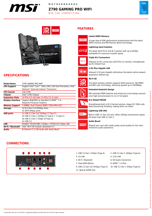
© 2023 Micro-Star Int'l Co.Ltd. MSI is a registered trademark of Micro-Star Int'l Co.Ltd. All rights reserved.SPECIFICATIONSModel Name Z790 GAMING PRO WIFICPU Support Support Intel ® Core™ 14th/ 13th/ 12th Gen Processors, Intel ®Pentium ® Gold and Celeron ® Processors CPU Socket LGA 1700ChipsetIntel ®Z790 ChipsetExpansion Slots 3x PCIe 4.0 x16 slots, 2x PCIe 3.0 x1 slotsDisplay Interface Support 4K@30Hz as specified in HDMI™ 1.4 –Requires Processor GraphicsMemory Support 4 DIMMs, Dual Channel DDR5-7200+MHz (OC)Storage 3x M.2 Gen 4 x4 64Gbps slots,4x SATA 6Gbps portsUSB ports1x USB 3.2 Gen 2x2 20Gbps (1 Type-C),4x USB 3.2 Gen 2 10Gbps (3 Type-A + 1 Type-C),8x USB 3.2 Gen 1 5Gbps (8 Type-A),4x USB 2.0LANRealtek ® RTL8125BG 2.5Gbps + RTL8111H 1Gbps LANWi-Fi / Bluetooth Intel ®Wi-Fi 6E module, Bluetooth 5.3Audio8-Channel (7.1) HD Audio with Audio BoostOnboard 2.5G plus Gigabits LAN deliver the better online network experience without lag.Wi-Fi 6EThe latest wireless solution supports 6GHz spectrum, MU-MIMO and BSS color technology, delivering speeds up to 2400Mbps.Extended Heatsink DesignMSI extended PWM heatsink and enhanced circuit design ensures even high-end processors to run in full speed.M.2 Shield FROZRStrengthened built-in M.2 thermal solution. Keeps M.2 SSDs safe while preventing throttling, making them run faster.Lightning USB 20GBuilt-in USB 3.2 Gen 2x2 port, offers 20Gbps transmission speed,4X faster than USB 3.2 Gen 1.Audio BoostReward your ears with studio grade sound quality for the most immersive audio experience.CONNECTIONS1. USB 3.2 Gen 1 5Gbps (Type-A)3. 1G LAN5. Wi-Fi / Bluetooth 7. Flash BIOS Button9. USB 3.2 Gen 2x2 20Gbps (Type-C)11. Optical S/PDIF-Out2. USB3.2 Gen 2 10Gbps (Type-A)4. 2.5G LAN6. HD Audio Connectors 8. HDMI™ 1.4 Port10. USB 3.2 Gen 1 5Gbps (Type-A)G e n e r a t e d 2023-10-24, c h e c k f o r t h e l a t e s t v e r s i o n w w w .m s i .c o m /d a t a s h e e t . T h e i n f o r m a t i o n p r o v i d e d i n t h i s d o c u m e n t i s i n t e n d e d f o r i n f o r m a t i o n a l p u r p o s e s o n l y a n d i s s u b j e c t t o c h a n g e w i t h o u t n o t i c e .。
ceo coo功能
ceo coo功能
CEO(首席执行官)和COO(首席运营官)是企业中两个非常重要的职位。
他们在公司的管理层中扮演着关键的角色,各自拥有不同的职责和职能。
CEO通常负责公司的战略规划和决策,而COO则负责实施这些决策并管理日常运营。
作为CEO,他是公司的领导者和决策者。
他需要制定公司的长期发展战略,并确保公司朝着正确的方向前进。
他需要与各部门的负责人合作,协调各项工作,确保公司的整体利益。
此外,CEO还需要与投资者、合作伙伴和其他利益相关者进行沟通和协商,以确保公司的声誉和利益得到保护。
COO作为首席运营官,负责公司的日常运营和管理。
他需要监督各个部门的工作,确保公司的运营效率和质量。
他需要与各部门的经理合作,优化业务流程,提高生产效率。
此外,COO还需要负责制定和执行公司的运营策略,确保公司的运营目标得到实现。
CEO和COO之间的合作是非常重要的。
他们需要共同制定公司的长期战略,并确保这些战略能够在运营层面得到有效实施。
CEO和COO之间需要建立良好的沟通渠道,以便及时了解彼此的想法和意见。
他们需要相互协作,共同解决公司面临的问题和挑战。
CEO和COO是企业中非常重要的职位。
他们分别负责公司的战略规划和日常运营,共同推动公司的发展。
他们之间的合作和沟通对于
公司的成功至关重要。
只有CEO和COO能够紧密合作,才能够将公司带向更高的高度。
ceo职位说明书

ceo职位说明书一、职位概述CEO即首席执行官(Chief Executive Officer),是公司中最高层次的管理者。
CEO负责整体战略规划与决策,确保公司的长期发展和利益最大化,同时承担着领导员工团队、激发创新和塑造企业文化的重要责任。
二、职责与要求1. 战略规划与决策:制定和执行公司的整体战略,确保公司的发展方向与目标一致,及时调整战略以应对市场变化。
对重大决策负责,包括公司投资、合作伙伴选择等。
2. 领导团队:组建并领导高效的管理团队,激励员工的创新与执行力,提高团队协作和沟通能力。
确保公司各部门、各层级之间的协调与合作,实现共同目标。
3. 资源管理与风险控制:合理分配资源,有效管理公司的财务、人力和物力资源。
对公司的风险进行评估和控制,制定应对措施,确保公司的可持续发展。
4. 市场开拓与拓展:开拓新市场,寻求合作与商机,扩大公司的业务范围和市场份额。
建立并维护与客户、供应商和利益相关者的良好关系,提升公司的声誉和品牌价值。
5. 制定企业文化:塑造和传承公司的核心价值观和企业文化,为员工提供良好的工作环境和发展空间。
倡导并推动企业社会责任,落实可持续发展战略。
三、背景与能力要求1. 教育背景:本科及以上学历,管理学、经济学或相关专业优先考虑。
2. 工作经验:至少10年以上相关行业工作经验,其中包括5年以上管理层经验。
具备创业、拓展新市场的经验者优先。
3. 领导力与决策能力:具备卓越的领导能力和战略思维,善于团队管理、激励和决策。
能够在复杂的环境下做出准确、果断的决策。
4. 行业洞察力与创新精神:对行业动态有敏锐的洞察力,能够抓住机遇,推动创新与变革。
5. 沟通与协调能力:良好的沟通、协调和谈判能力,能够有效管理公司内外部的关系,解决问题并达成共识。
6. 诚信与责任感:具备高度的诚信和职业道德,能够以身作则,以全面负责的态度履行职责。
四、待遇与福利公司将为CEO提供具有竞争力的薪酬待遇和丰厚的激励机制。
CEO、CSO职位简介
岗位:董事长CEO
集团的战略制定及执行
1、主持股东大会和召集、主持董事会会议,并负责上述会议的决议的贯彻落实;
2、组织讨论和决定公司的发展规划、经营方针、年度计划以及日常经营工作中的重大事项;
3、决定公司高层管理人员的聘用和解职、报酬、待遇和支付方式,并报董事会批准备案;签署批准调入公司的各级管理人员;
4、签署对外上报、印发的各种重要报表、文件、资料;签署公司重要合同和协议;
5、处理检督部门的管理工作的重大事项;
6、总结审核,组织审批公司实现规划目标业绩,主持公司内外的一切重大活动。
岗位:首席科学家CSO
主持集团研发工作
1、负责调研行业动态、研发项目信息,组织制定集团公司中、长期产品研发和发展战略计划;
2、统筹、指导各研发项目实施方案,评估技术瓶颈并提出解决方案,提供指导性意见;
3、负责带领研发团队推进研发项目的研究工作,解决开发过程中的关键技术问题;
4、负责集团研发人才的梯队建设、组织能效提升、技术能力构建工作;
5、负责识别心血管医疗器械行业发展趋势,顺应趋势制定集团发展战略及投资方向。
首席执行官ceo岗位职责(二篇)
首席执行官ceo岗位职责首席执行官(CEO)是一家公司的最高领导,负责制定和实施公司的战略目标和业务发展计划。
以下是CEO的岗位职责:1. 制定公司的战略方向和发展策略,确保公司能够实现长期可持续发展;2. 担任公司的发言人,代表公司与外界进行沟通和协调;3. 组织和管理公司的日常运营,确保公司的各项业务活动顺利进行;4. 领导公司的高级管理团队,指导和激励员工,确保公司的团队合作和有效管理;5. 监督公司的财务状况,确保公司的财务稳健和可持续增长;6. 管理公司的风险,制定风险管理策略和措施,保护公司免受不利因素的影响;7. 与董事会合作,制定公司的治理结构和政策,确保公司的合规性和透明度;8. 研究市场动态和竞争对手情况,及时调整公司的经营策略,保持竞争优势;9. 与合作伙伴和投资者进行有效的沟通和合作,建立和维护良好的关系;10. 提供领导力和激励,培养和发展公司的高级管理人员,确保公司的人才储备和继任计划。
总而言之,CEO是公司的最高决策者和执行者,负责推动公司的发展,保持公司的竞争力和盈利能力,并创造价值给股东和各利益相关方。
首席执行官ceo岗位职责(二)1、领导执行、实施董事长的各项决议:全面领会董事长的各项决议内容及其重要意义、组织实施董事长的各项决议;对各项决议的实施过程进行监控,发现问题及时纠正,确保决议的贯彻执行。
2、实施公司的总体战略:组织实施集团公司的发展战略,发掘市场机会,领导创新与变革。
3、根据董事长下达的年度经营目标组织制定、修改、实施公司年度经营计划。
4、建立良好的沟通渠道:负责与董事长保持良好沟通,定期向董事长汇报经营战略和计划执行情况、资金运用情况和盈亏情况、机构和人员调配情况及其他重大事宜;领导建立公司与客户、供应商、合作伙伴、上级主管部门、政府机构、金融机构、媒体等部门间顺畅的沟通渠道;领导开展公司的社会公共关系活动,树立良好的企业形象、领导建立公司内部良好的沟通渠道。
my dream英语作文ceo

my dream英语作文ceoCEO" with over 1000 words in English:I have always been fascinated by the world of business and the power of leadership. From a young age, I have dreamed of one day becoming a CEO, leading a successful company and making a lasting impact on the industry. This dream has been a driving force in my life, shaping my academic and professional pursuits, and guiding me towards the ultimate goal of becoming a Chief Executive Officer.As a child, I was always intrigued by the stories of successful entrepreneurs and the companies they had built from the ground up.I marveled at their ability to navigate the complexities of the business world, make strategic decisions, and inspire their teams to achieve greatness. These individuals seemed to possess a unique blend of vision, intelligence, and charisma that I aspired to emulate.Throughout my education, I have diligently pursued a path that would prepare me for the challenges of becoming a CEO. I have excelled academically, earning a degree in business administration with a focus on strategic management. During my time in university, I have had the opportunity to participate in various extracurricularactivities, such as student government and entrepreneurship clubs, which have honed my leadership skills and provided me with valuable real-world experience.In addition to my academic achievements, I have also gained practical experience through internships and part-time jobs in the corporate world. These experiences have given me a deeper understanding of the inner workings of businesses, the decision-making processes, and the challenges that leaders face on a daily basis. I have learned to navigate the complexities of office politics, work effectively in teams, and make informed decisions under pressure.As I have progressed through my career, my passion for becoming a CEO has only grown stronger. I am constantly seeking out opportunities to expand my knowledge and skills, whether it's through attending industry conferences, reading business literature, or networking with experienced professionals. I am driven by a desire to constantly improve and challenge myself, to push the boundaries of what I am capable of and to leave a lasting impact on the organizations I am a part of.One of the key aspects of my dream to become a CEO is the opportunity to lead and inspire a team of talented individuals. I believe that the role of a CEO is not just about making strategicdecisions, but also about creating a culture of excellence, empowering employees, and fostering a shared vision for the company's success. I am excited by the prospect of building a strong, cohesive team that is aligned with the company's mission and values, and working together to achieve ambitious goals.Another important aspect of my dream is the opportunity to make a positive impact on the broader community. As a CEO, I would have the platform and resources to address pressing social and environmental issues, and to use the company's influence to drive positive change. I am passionate about sustainability, corporate social responsibility, and the role that businesses can play in creating a more equitable and sustainable future.Of course, I am under no illusion that becoming a CEO is an easy or straightforward path. I understand that the road to the top is filled with challenges, setbacks, and fierce competition. However, I am confident in my abilities and my determination to succeed. I am willing to put in the hard work, the long hours, and the relentless pursuit of excellence that is required to reach the pinnacle of my profession.In conclusion, my dream of becoming a CEO is a deeply personal and ambitious goal that has been a driving force in my life. I am passionate about the world of business, the power of leadership, andthe opportunity to make a positive impact on the organizations and communities I serve. While the path ahead may be challenging, I am committed to pursuing this dream with unwavering determination and a steadfast belief in my ability to achieve it.。
CEO职责范文4篇

CEO职责范文4篇(经典版)编制人:__________________审核人:__________________审批人:__________________编制单位:__________________编制时间:____年____月____日序言下载提示:该文档是本店铺精心编制而成的,希望大家下载后,能够帮助大家解决实际问题。
文档下载后可定制修改,请根据实际需要进行调整和使用,谢谢!并且,本店铺为大家提供各种类型的经典范文,如演讲稿、总结报告、合同协议、方案大全、工作计划、学习计划、条据书信、致辞讲话、教学资料、作文大全、其他范文等等,想了解不同范文格式和写法,敬请关注!Download tips: This document is carefully compiled by this editor.I hope that after you download it, it can help you solve practical problems. The document can be customized and modified after downloading, please adjust and use it according to actual needs, thank you!In addition, this shop provides you with various types of classic sample essays, such as speech drafts, summary reports, contract agreements, project plans, work plans, study plans, letter letters, speeches, teaching materials, essays, other sample essays, etc. Want to know the format and writing of different sample essays, so stay tuned!CEO职责范文4篇鲁克留给我们的最后也是他最新的管理思想就是2004年10月1日,他在美国德鲁克档案馆举办的“智者对话”上精辟地阐述了21世纪CEO的职责。
企业中高层领导称呼的英文缩写CEOCFOCOO全面解释
CEOCEO(Chief Executive Officer),即首席执行官,是美国人在20世纪60年代进行公司治理结构改革创新时的产物,它的出现在某种意义上代表着将原来董事会手中的一些决策权过渡到经营层手中。
在中国,CEO这个概念最早出现在一些网络企业中。
在那里,CEO往往是自封的,也很少有人去研究这一称谓对企业到底意味着什么。
但是,当“CEO”在中国叫得越来越响的时候,我们应该认识到,高层人员称谓的改变不是一件小事,设立CEO职位不应仅仅是对时尚的追赶。
CFOCFO(Chief Financial Officer)意指公司首席财政官或财务总监,是现代公司中最重要、最有价值的顶尖管理职位之一,是掌握着企业的神经系统(财务信息)与血液系统(现金资源)灵魂人物。
做一名成功的CFO需要具备丰富的金融理论知识与实务经验。
公司理财与金融市场交互、项目估价、风险管理、产品研发、战略规划、企业核心竞争力的识别与建立以及洞悉信息技术及电子商务对企业的冲击等自然都是CFO职责范围内的事。
在一个大型公司运作中,CFO是一个穿插在金融市场操作与公司内部财务管理之间的角色。
担当CFO的人才大多是拥有多年在金融市场驰骋经验的人。
在美国,优秀的CFO常常在华尔街做过成功的基金经理人。
COO首席营运官【COO】chief Operation officer 的职责主要是负责公司的日常营运,辅助CEO的工作。
一般来讲,COO负责公司职能管理组织体系的建设,并代表CEO处理企业的日常职能事务。
如果公司未设有总裁职务,则COO还要承担整体业务管理的职能,主管企业营销与综合业务拓展,负责建立公司整个的销售策略与政策,组织生产经营,协助CEO制定公司的业务发展计划,并对公司的经营绩效进行考核。
还有:首席品牌官【CBO】chief brand officer首席文化官【CCO】Chief Cultural Officer开发总监【CDO】chief Development officer首席执行官【CEO】Chief Executive officer首席财务官【CFO】Chief finance officer人事总监【CHO】Chief Human resource officer首席信息官【CIO】chief information officer首席知识官【CKO】chief knowledge officer首席市场官【CMO】chief Marketing officer首席谈判官【CNO】chief Negotiation officer首席营运官【COO】chief Operation officer公关总监【CPO】chief Public relation officer质量总监【CQO】chief Quality officer销售总监【CSO】chief Sales officer首席技术官【CTO】chief Technology officer评估总监【CVO】chief Valuation officerCAO:Answerer 首席答辩人,专门负责解答媒体、债权人与用户等有关网站倒闭问题的询问。
Philips Series 7000 湿干电子剃须刀说明书

S7782/71shave, advanced skin protectionwith SkinIQ TechnologyThe Philips Series 7000 glides smoothly over your skin, while cutting each hairclose - even on 3-day beards. Equipped with advanced SkinIQ technology, theshaver senses, adapts and guides on the correct motion, for better skin protection.A close shaveFollows the contours of your faceMore cutting performance in every strokeGuides hair into the optimal cutting positionSkinIQ technologyGuides you to an improved shaving techniqueMaster your technique with the Philips GroomTribe appA shaver with the power to tame beardsA shaver that reduces friction to minimize irritationFor a convenient shaveChoose a convenient dry or refreshing wet shaveEven-up your mustache and sideburns60 minutes of shaving from a 1-hour chargePowerful cleaning pod for maintenance and hygieneFully charged in one hourHighlightsProtective SkinGlidecoatingA protective coating lies between the shaver heads and your skin . Made of up to 2.000micro -tech beads per square millimetre , it reduces friction on skin by 25%*, to minimize irritation .SteelPrecisionbladesPowerful yet gentle , the 45 self -sharpening SteelPrecision blades on this Philips shaver complete up to 90,000 cutting actions per minute , cutting more hair per stroke ** for a clean , comfortable finish .Motion ControlsensorA n electric shaver motion -sensing technology tracks how you shave and guides you to a more e fficient technique . A fter just threeshaves , the majority of men achieved a better shaving technique for fewer passes ***.Personalization viaappPair your Philips electric shaver to theGroomTribe app and prepare to master your technique . Just track your progress and personalize your routine to achieve a shave that 's both close and kind .Power A daptsensorThe electric shaver has intelligent facial -hair sensor that reads hair density 125 times per second . The technology auto -adapts cutting power for an e ffortless and gentle shave .360-D FlexingheadsDesigned to follow the contours of your face ,this Philips electric shaver has fully flexible heads that turn 360° for a thorough and comfortable shave .Hair -Guide precisionheadsThis new shape precision shaver is enhanced with hair guiding channels for optimal cutting and skin comfort .Cable -free Quick CleanPod10x more e ffective than cleaning with water ****, the powerful cleaning podthoroughly cleans and lubricates your shaver in just 1 minute . Using it helps maintain shaver performance and increase hygiene .Shave wet ordryA wet and dry shaver that adapts to yourpreference . Choose a convenient dry shave , or pair with your favourite foam or gel for a refreshing wet shave .SpecificationsA ccessoriesMaintenance: Cleaning brushQuick Clean Pod: 1 cartridge included, Yes Integrated pop-up trimmerTravel and storage: Travel caseSoftwareA pp: GroomTribe, Connects via Bluetooth®Software update: Philips offers relevant software updates for a period of 2 years after the date of purchaseSmartphone compatibility: iPhone andA ndroid™ devices PowerCharging: 1 hour full charge, 5 min quick chargeBattery type: Li-ionRun time: 60 minutesA utomatic voltage: 100-240 VStand-by power: 0.04 WMax power consumption: 9 WDesignHandle: Rubber gripColor(s): Midnight BlueShaving heads: A ngularService2-year warrantyReplacement head SH71: Replace every 2 yrswith SH71Shaving PerformanceContour following: 360-D Flexing headsShaving system: SteelPrecision bladesSkinIQ technology: Protective SkinGlidecoating, Motion Control sensor, Power A daptsensorEase of useCleaning: One-touch open, Fully washableDisplay: Motion control indicator, LED display,Battery level indicator, Travel lockWet & Dry: Wet and dry useSmartClick attachmentFits product type: RQ585/51 DOES NOT fitangular head type* compared to non-coated material* * Tested versus Philips Series 3000.* * * Based on Philips Series S7000 and GroomTribe appusers in 2019.* * * * comparing shaving debris after using cleaning fluidvs. water in the cartridge© 2023 Koninklijke Philips N.V.A ll Rights reserved.Specifications are subject to change without notice. Trademarks are the property of Koninklijke Philips N.V. or their respective owners.Issue date 2023‑08‑21 Version: 5.5.1 。
ceocfocoo岗位职责
ceocfocoo岗位职责第1篇:CEO、CFO、COO是什么意思?CEO、CFO、COO是什么意思?CAO: Art 艺术总监CBO: Busine 商务总监CCO: Content 内容总监CDO: Development 开发总监CEO: Executive 首席执行官CFO: Finance 财务总监CGO: Gonverment 政府关系CHO: Human resource 人事总监CIO: Information 技术总监CJO: Jet 把营运指标都加一个或多个零使公司市值像火箭般上升的人CKO: Knowledge 知识总监CLO: Labour 工会主席CMO: Marketing 市场总监CNO: Negotiation 首席谈判代表COO: Operation 首席营运官CPO: Public relation 公关总监CQO: Quality control 质控总监CRO: Research 研究总监CSO: Sales 销售总监CTO: Technology 首席技术官CUO: User 客户总监CVO: Valuation 评估总监CWO: Women 妇联主席CXO: 什么都可以管的不管部部长CYO: Yes 什么都点头的老好人CZO: 现在排最后,等待接班的太子CEO(Chief executive officer)首席执行官类似总经理、总裁,是企业地法人代表。
COO(Chief operating officer)首席运营官类似常务总经理CFO(Chief financial officer)首席财务官类似财务总经理CTO(Chief technology officer)首席技术官类似总工程师CIO(Chief information officer)首席信息官主管企业信息地收集和发布现在地CXO满天飞,不是XO洋酒,也不是XO酱,咱们说地都是各公司地高层,什么CEO,CFO,CIO,CTO啦。
CEO的职务说明
CEO的职务说明CEO是Chief Executive Officer的缩写,即首席执行官。
作为企业的高层管理者,CEO承担着组织和协调企业日常运营和战略发展的任务。
下面是CEO的职务说明:首先,CEO应制定企业的发展战略和目标。
CEO需要对企业的外部环境进行深入的研究和分析,了解市场趋势、竞争对手和消费者需求等因素,然后制定合适的发展战略和目标,确保企业能够在竞争激烈的市场中取得持续的竞争优势。
其次,CEO应建立一个高效的管理团队。
CEO需要聘请和培养具有优秀专业能力和团队合作精神的高级管理人才,并且激励他们充分发挥自己的才华和创造力。
CEO应确保每个部门都有合适的人员和资源,使得企业各部门之间能够紧密合作,协同努力实现公司的目标。
第三,CEO应发展和维护企业文化。
CEO应明确和传达企业的核心价值观和道德准则,引导员工们以正确的心态和行为来推动企业的发展。
CEO还应鼓励员工创新和学习,提供良好的培训和发展机会,促进员工的职业成长和个人发展。
第四,CEO应确保企业的财务健康和持续增长。
CEO需要制定有效的财务管理策略,控制企业运营成本和资金使用,及时调整业务结构和资源配置,以确保企业的盈利能力和可持续发展。
第五,CEO应与股东和投资者保持良好的关系。
CEO需要积极与股东和投资者沟通,及时向他们汇报企业的经营状况和未来发展计划,解答他们的疑虑和关注,并且根据他们的需求和期望进行有效的决策和执行。
总结起来,CEO是企业的领导者和决策者,需要具备战略思维、领导能力、沟通能力、创新能力和管理能力等全方位的素质。
只有通过有效的角色定位和职责履行,CEO才能带领企业顺利应对变革和挑战,并推动企业持续发展。
CEO经理岗位职责

CEO经理岗位职责CEO (Chief Executive Officer,即首席执行官)是公司的最高管理职位,其职责是领导公司发展,制定和实施企业的长期战略规划。
CEO要求具有出色的领导力、沟通能力、战略思维、决策能力和团队合作能力。
CEO岗位职责主要包括以下几个方面:1. 制定并实施企业战略计划。
CEO应该站高处,把握企业的发展方向,明确公司的目标和愿景,并根据市场变化和公司自身情况,制定企业战略计划。
执行计划需要启发并协调团队完成任务,保证进度和效果。
2. 管理和监督公司管理团队。
作为企业的最高经营者,CEO需要管理和监督领导和团队,确保每个人都能够素质过硬且各司其职。
其首要位置是指导和监察管理层,以确保公司目标的实现。
3. 确定、监督和控制公司预算。
实现财务目标是CEO的一项主要职责之一。
因此,CEO必须确保公司的财务状况稳定,并通过制定财务计划和预算控制公司资金的开支,以实现长期的财务目标。
4. 监督公司的销售和营销。
CEO需要对公司的销售业绩进行监督,执行正确的销售能力和营销策略,以保持公司的利润、市场份额和市场领先优势。
5. 建立和加强企业与客户和同业之间的关系。
CEO需要建立和加强公司和客户、同业和其他关系之间的联系,以实现公司的凝聚力和支撑力。
同时,CEO还应该积极参与行业内的议题和活动,以加强企业在行业内的影响力和竞争优势。
6. 加强公司的社会责任感。
CEO应该敏锐地理解企业应承担的社会责任,培养公司社会责任感,推进公司的公益活动,以加强公司的社会形象,获取更多的支持和理解。
CEO是搭建公司发展路线的枢纽,根据企业的发展战略,CEO要通过创新、领导力与管理能力,带领公司走向成功。
- 1、下载文档前请自行甄别文档内容的完整性,平台不提供额外的编辑、内容补充、找答案等附加服务。
- 2、"仅部分预览"的文档,不可在线预览部分如存在完整性等问题,可反馈申请退款(可完整预览的文档不适用该条件!)。
- 3、如文档侵犯您的权益,请联系客服反馈,我们会尽快为您处理(人工客服工作时间:9:00-18:30)。
中国独角兽CEO的硅谷反思:这3个字,90%的中国企
业都没做好
本文作者:硅谷密探
30个来自腾讯青腾大学的创业公司CEO,聚集在硅谷PaloAlto的WholeFoods门口。
亚马逊大手笔137亿美元收购WholeFoods的新闻刚刚宣布不久,这家零售企业吸引了大家的注意。
“上次我在波士顿和一个哈佛的教授交流,他们把我们永辉写到了哈佛商业案例里,他跟我说WholeFoods就是美国零售业的未来,有机会一定要做中国的WholeFoods”,永辉超市创始人张轩宁在大家走进WholeFoods前介绍说。
而走进去之后,一帮身价上亿的CEO开始讨论WholeFoods的选品策略。
除了感慨亚马逊的新零售布局,大家也顺便感叹了一下美国的蓝莓居然换成人民币后还比国内便宜,草莓也比国内的好吃。
但一堆创业者组队出现在硅谷,除了在WholeFoods买点吃的,显然有所希冀。
青腾学员于西雅图参观波音公司商用飞机制造厂
新思维:中国公司缺乏使命感
这是一次中美间的深度交流,这30多位创业者多涉足零售、金融、教育、内容各种垂直行业。
8天的日程里,腾讯青腾大学安排了Google、LendingClub、英伟达、SingularityUniversity等的参观和交流,在斯坦福的学习和宣讲,以及与YCombinator合伙人的密谈等。
这些国内的创业者们有机会亲身体会新零售技术在美国发展的如何,人工智能如何在硅谷落地,互联网金融在技术上中美之间的差异。
除了技术的先进,大家也贪婪的吸收硅谷新思维,而这个其实带来的震撼比技术更大。
参观北美最大的医药批发商麦克森
最大的感慨其实是对使命感的追求。
胖吴货栈创始人吴则飞发现,他在硅谷参访的每个企业都不断的强调它的愿景、使命、价值观,而一个企业所有的进步和所有的生态其实都围绕着使命愿景和价值观做。
这个给他的震撼非常大,而中国的很多公司经常做着做着就忘了。
随行游学导师、腾讯培训专家徐昊对此也感慨颇深,对于COSTCO,国内对其商业模式
极其清楚了,但是国内的观察只是停在了商业模式层面,只是冰山的一角。
令他感慨的是COSTCO所做事的原则,我只收你会员费,我替你把关所有的质量。
这种为用户服务的使命感体现在方方面面,比如1.5美元的热狗和汽水的组合,已经30年没提高过价格了,而COSTCO的汽油的会员价格明显低于其他加油站,每次路过都是长龙。
正是这种对使命感坚持,老会员的续费率在北美达到了91%。
所参访企业无不谈自己的愿景、使命和价值观
轻松筹创始人杨胤对硅谷企业对愿景的强烈追求也感触颇深,真正的把愿景落实到了公司的每一个好的问题、好的战略和人才培养的细节中。
TStudy创始人田雪松对硅谷企业的使命感也有强烈的共鸣,“先有东西去赚钱,赚着赚着我再总结愿景,这种情况也不是不好,但是后总结的东西,其实是硬找出来的东西”。
而
硅谷的公司无论大小,在创业之初,都给自己顶一个自己的理想、目标、愿景,解决一个什么样有价值的社会问题。
除了使命感,对设计和用户的关注也是一大启发。
斯坦福大学的BarryKatz讲述的设计思维,换位思考->定义->设想->原型->测试的流程里,以人为本的设计,一样用户为源头,以故事为载体,通过情景再现来挖掘人性需求,而不是以技术为源头去空想需求的理念让青腾大学的学员耳目一新。
设计思维这套方法论在国内可能水土不服,但设计应该贯穿到整个公司的上层建筑的设计,逻辑和架构的设计,再到产品的设计。
回收宝CTO叶飞也感慨,“文化有异同,但人性是相通的,产品无处不在,精心打造细节,就是壁垒”。
斯坦福商学院的RobertBurgelman讲的战略领导力也让永辉超市创始人张轩宁感慨,过去的控制型战略已经有点跟不上时代,新一代的公司关系都是互相依存和互相依赖的。
新技术:硅谷技术依旧领先
中国的商业模式创新的成就有目共睹,连YCombinator的合伙人Anu也承认其实中国在很多的方面已经弯道超车了,包括像微信、移动支付等。
所以技术的交流是这些创业者最想要的。
在英伟达的DemoRoom里,大家看到英伟达打造的强大的人工智能个人超级计算机DGX 以及其展示的AI能力,都殷切的关心这些AI技术如何应用到自己的领域。
田雪松已经大量在他们的产品中使用计算机视觉,他非常关注新的人工智能技术如何改善传统教育行业。
Linkedin的大数据架构也让贝贝网联合创始人柯尊尧打开认知,大数据驱动的网络互联让人才大战硝烟弥漫。
而在与微软HoloLens相关负责人交流的时候,在座的CEO都关心语音、脑电波是否能和视觉一起改造未来的人机交互。
“硅谷的技术在不少领域是领先几年的,硅谷的很多公司都是技术驱动”,不少CEO都暗自感慨。
出海:Copyfrom C hina
不过在2017年来考察硅谷,与5年前来硅谷,体会完全不一样。
从“copyto China”到“copyfrom C hina”,风向变了。
而这群来自中国的创业者,开始考虑用中国的产品和运营,做出海的生意。
其实“copytoChina”早就有了先例,除了大家熟悉的微信,不少美国都已经用上了共享单车。
青腾学员一行还在异国他乡看到漂洋过海的共享单车,他们兴奋的合影留念。
“美国很多地方实在是太村了,方圆几公里都没有几家店”,西少爷创始人孟兵感慨,“不过旧金山、纽约这些地方都不错,全球都在经历消费升级,我觉得对于美国的很多战略性的东西基本上思考到五六成了,可能以后还需要一些积累,很快就可以去开拓美国市场了”。
想开拓美国市场的不止有孟兵,轻松筹创始人杨胤早已在硅谷开了一个办公室,下一步是做美国市场的运营和推广。
而不少CEO已经开始考虑未来如何在硅谷当地开办公司。
挖人:硅谷最重要的是人才
不过说回硅谷的核心,依旧是人,萨摩耶金服产品负责人马驰骋此行感慨颇深,“湾区的公司技术驱动氛围非常浓厚,技术驱动是基因里的东西。
”而技术背后,更重要的是人。
第二届青腾中美创业论坛暨硅谷高端人才招聘会
而“硅谷游”的另一面,是一场巡演,背后的期待也很明显。
在斯坦福的中美创业论坛,30位CEO与300名来自斯坦福等学校的硅谷高端人才面对面交流。
虽然是叫中美创业论坛,但现场的招聘环节却是最火爆的。
固生堂创始人涂志亮来硅谷找高端人才的计划由来已久,在会场有几个斯坦福的学生找到他与他交流。
还有一个医学信息博士和他后续见了面深谈,希望在医学信息数据挖掘上有
所突破。
现场招聘环节火爆
涂志亮表示他们还需要AI算法和人脸识别的人才,而毕业三年的技术人员,他们能给到20-30万美元的待遇。
轻松筹创始人杨胤在中美创业论坛现场还遇到了几个利用轻松筹平台获得帮助的学子,他们都表达了加入轻松筹的意愿。
而杨胤对数据增长、机器学习、区块链技术方面的人才极
度渴求。
张首晟教授与青腾学员共进晚餐
在腾讯安排的参观活动之外,他们把日程安排得满满当当。
田雪松几乎用尽所有空隙时段,在硅谷安排了几场面试。
他的目标很明确,需要优秀的图像识别、搜索工程和算法工程师,3到5年工作经验的工程师他们可以给到每年30万美元的待遇。
本土化与国际化的融合,能否有承受挫折与挑战的能力,期望值与现实的妥协,工作强度的差异,这些都是硅谷人才回国面临的挑战。
大家都认同中国是个巨大的市场,有巨大的机会,归不归的确是不少工程师一直在考虑的
问题,而中美发展也日新月异,明年的硅谷也许又不一样?
作者介绍:
硅谷密探(w )是一家扎根于美国硅谷的科技新媒体。
为您带来正在发生的全球科技创新秘闻。
我们深度剖析海外产品、直播硅谷动态,连接中美创业者。