TC76_Simplified_Chinese
IBM Storwize V7000 信息中心勘误表说明书
IBM System Storage SAN Volume ControllerIBM Storwize V7000Information Center ErrataVersion 6.3.0April 27, 20121Contents Introduction (4)Who should use this guide (4)Last Update (4)Change History (4)iSCSI Limits (5)iSCSI Limits with Multiple I/O Groups (5)Definition of terms (5)Limits that take effect when using iSCSI (6)Single I/O Group Configurations (6)iSCSI host connectivity only (6)Mixed iSCSI and Fibre Channel host connectivity (6)Multiple I/O Group Config (7)Symptoms of exceeding the limits (7)Configuring the HP 3PAR F-Class and T-Class Storage Systems (8)Minimum Supported STORWIZE V7000 Version (8)Configuring the HP 3PAR Storage System (8)Supported models of HP 3PAR Storage Systems (8)Support firmware levels of HP 3PAR storage arrays (8)Concurrent maintenance on HP 3PAR storage arrays (8)HP 3PAR user interfaces (8)HP 3PAR Management Console (9)HP 3PAR Command Line Interface (CLI) (9)Logical units and target ports on HP 3PAR storage arrays (9)LUNs (9)LUN IDs (9)LUN creation and deletion (10)LUN Presentation (10)Special LUNs (10)LU access model (11)LU grouping (11)LU preferred access port (11)Detecting Ownership (11)Switch zoning limitations for HP 3PAR storage arrays (11)Fabric zoning (11)Target port sharing (11)Controller splitting (12)Configuration settings for HP 3PAR storage array (12)Logical unit options and settings for HP 3PAR storage array (12)Creation of CPG (12)Set up of Ports (13)Setup of Host (14)LUN creation (15)Host options and settings for HP 3PAR storage array (16)2Quorum disks on HP 3PAR storage arrays (16)Clearing SCSI reservations and registrations (17)Copy functions for HP 3PAR storage array (17)Thin Provisioning for HP 3PAR storage array (17)Recommended Settings for Linux Hosts (18)Multipath settings for specific Linux distributions and Releases (19)Udev Rules SCSI Command Timeout Changes (21)Editing the udev rules file (22)3IntroductionThis guide provides errata information that pertains to release 6.3.0 of the IBM System Storage SAN Volume Controller Information Center and the IBM Storwize V7000 Information Center.Who should use this guideThis errata should be used by anyone using iSCSI as a method to connect hosts, Connecting Linux hosts using Fibre Channel or when connecting HP 3PAR Storage to IBM System Storage SAN Volume Controller or IBM Storwize V7000 .Last UpdateThis document was last updated: April 27, 2012.Change HistoryThe following revisions have been made to this document:Revision Date Sections ModifiedNov 18, 2011 New publicationApr 27 2012 Linux Host SettingsTable 1: Change History4iSCSI LimitsiSCSI Limits with Multiple I/O GroupsThe information is in addition to, and a simplification of, the information provided in the Session Limits pages at the following links:/infocenter/StorwizeV7000/ic/index.jsp?topic=/com.ibm.storage.Storwize V7000.console.doc/StorwizeV7000_iscsisessionlimits.html/infocenter/storwize/ic/topic/com.ibm.storwize.v7000.doc/S torwize V7000_iscsisessionlimits.htmlDefinition of termsFor the purposes of this document the following definitions are used:IQN:an iSCSI qualified name – each iSCSI target or initiator has an IQN. The IQN should be unique within the network. Recommended values are of the formiqn.<date>.<reverse domain name>:<hostname>.<unique id> e.g. iqn.03-.ibm.hursley:host1.1initiator: an IQN that is used by a host to connect to an iSCSI targettarget: an IQN on an STORWIZE V7000 or V7000 node that is the target for an iSCSI logintarget portal: an IP address that can be used to access a target IQN. This can be either an IPv4 or an IPv6 address.5Limits that take effect when using iSCSISingle I/O Group ConfigurationsiSCSI host connectivity only1 target IQN per node2 iSCSI target portals (1xIPv4 and 1xIPv6) per network interface on a node4 sessions per initiator for each target IQN256 defined iSCSI host object IQNs512 host iSCSI sessions per I/O group **256 host iSCSI sessions per node (this is to allow the hosts to reconnect in the event of a failover)** e.g. if a single initiator logs in 3 times to a single target count this as 3. If a singleinitiator logs in to 2 targets via 3 target portals each count this as 6.Only the 256 defined iSCSI IQN limit is enforced by the GUI or CLI commands. Mixed iSCSI and Fibre Channel host connectivity512 total sessions per I/O group where:1 defined FC host object port (WWPN) = 1 session1 defined iSCSI host object IQN = 1 session1 additional iSCSI session to a target = 1 sessionIf the total number of defined FC ports & iSCSI sessions in an I/O group exceeds 512, some of the hosts may not be able to reconnect to the STORWIZE V7000/V7000 targets in the event of a node IP failover. See above section for help on calculating the number of iSCSI sessions.6Multiple I/O Group ConfigIf a host object is defined in more than one I/O group then each of its host object port definitions is counted against the session limits for every I/O group it is a member of. This is true for both FC and iSCSI host objects. By default a host object created using the graphical user interface is created in all available I/O groups.Symptoms of exceeding the limits.The following list is not comprehensive. It is given to illustrate some of the common symptoms seen if the limits defined above are exceeded.. These symptoms could also indicate other types of problem with the iSCSI network.•The host reports a time out during the iSCSI login process•The host reports a time out when reconnecting to the target after a STORWIZE V7000/V7000 node IP failover has occurred.In both of the above cases no errors will be logged by the STORWIZE V7000/V7000 system.7Configuring the HP 3PAR F-Class and T-Class Storage SystemsMinimum Supported STORWIZE V7000 Version6.2.0.4Configuring the HP 3PAR Storage SystemThis portion of the document covers the necessary configuration for using an HP 3PAR Storage System with an IBM Storwize V7000 cluster.Supported models of HP 3PAR Storage SystemsThe HP 3PAR F-Class (Models 200 and 400) the HP 3PAR T-Class (Models 400 and 800) are supported for use with the IBM STORWIZE V7000. These systems will be referred to as HP 3PAR storage arrays. For the latest supported models please visit /support/docview.wss?uid=ssg1S1003907Support firmware levels of HP 3PAR storage arraysFirmware revision HP InForm Operating System 2.3.1 (MU4 or later maintenance level) is the supported level of firmware for use with IBM STORWIZE V7000. For support on later versions, consult /support/docview.wss?uid=ssg1S1003907 Concurrent maintenance on HP 3PAR storage arraysConcurrent Firmware upgrades (“online upgrades”) are supported as per HP procedures. HP 3PAR user interfacesUsers may configure an HP 3PAR storage array with the 3PAR Management Console or HP 3PAR Command Line Interface (CLI).8HP 3PAR Management ConsoleThe management console accesses the array via the IP address of the HP 3PAR storage array. All configuration and monitoring steps are intuitively available through this interface.HP 3PAR Command Line Interface (CLI)The CLI may be installed locally on a Windows or Linux host. The CLI is also available through SSH.Logical units and target ports on HP 3PAR storage arraysFor clarification, partitions in the HP 3PAR storage array are exported as Virtual Volumes with a Virtual Logical Unit Number (VLUN) either manually or automatically assigned to the partition.LUNsHP 3PAR storage arrays have highly developed thin provisioning capabilities. The HP 3PAR storage array has a maximum Virtual Volume size of 16TB. A partition Virtual Volume is referenced by the ID of the VLUN.HP 3PAR storage arrays can export up to 4096 LUNs to the STORWIZE V7000 Controller (STORWIZE V7000’s maximum limit). The largest Logical Unit size supported by STORWIZE V7000 under PTF 6.2.0.4 is 2TB, STORWIZE V7000 will not display or exceeded this capacity.LUN IDsHP 3PAR storage arrays will identify exported Logical Units throughSCSI Identification Descriptor type 3.The 64-bit IEEE Registered Identifier (NAA=5) for the Logical Unit is in the form;5-OUI-VSID .The 3PAR IEEE Company ID of 0020ACh, the rest is a vendor specific ID.9Example 50002AC000020C3A.LUN creation and deletionVirtual Volumes (VVs) and their corresponding Logical Units (VLUNs) are created, modified, or deleted through the provisioning option in the Management Console or through the CLI commands. VVs are formatted to all zeros upon creation.To create a VLUN, highlight the Provisioning Menu and select the Create Virtual Volume option. To modify, resize, or destroy a VLUN, select the appropriate Virtual Volume from the window, right click when the specific VLUN is highlighted.*** Note: Delete the mdisk on the STORWIZE V7000 Cluster before deleting the LUN on the HP 3PAR storage array.LUN PresentationVLUNs are exported through the HP 3PAR storage array’s available FC ports by the export options on Virtual Volumes. The Ports are designated at setup and configured separately as either Host or Target (Storage connection). Ports being identified by a node : slot : port representation.There are no constraints on which ports or hosts a logical unit may be addressable.To apply Export to a logical unit, highlight the specific Virtual Volume associated with the Logical Unit in the GUI and right click and select Export.Special LUNsThere are no special considerations to a Logical Unit numbering. LUN 0 may be exported where necessary.Target PortsA HP 3PAR storage array may contain dual and/or quad ported FC cards. Each WWPN is identified with the pattern 2N:SP:00:20:AC:MM:MM:MM where N is the node, S is the slot and P is the port number on the controller and N is the controller’s address. The MMMMMM represents the systems serial number.Port 2 in slot 1 of controller 0 would have the WWPN of 20:12:00:02:AC:00:0C:3A The last 4 digits of serial number 1303130 in hex (3130=0x0C3A).This system has a WWNN for all ports of 2F:F7:00:02:AC:00:0C:3A.10LU access modelAll controllers are Active/Active. In all conditions, it is recommended to multipath across FC controller cards to avoid an outage from controller failure. All HP 3PAR controllers are equal in priority so there is no benefit to using an exclusive set for a specific LU.LU groupingLU grouping does not apply to HP 3PAR storage arrays.LU preferred access portThere are no preferred access ports on the HP 3PAR storage arrays as all ports are Active/Active across all controllers.Detecting OwnershipDetecting Ownership does not apply to HP 3PAR storage arrays.Switch zoning limitations for HP 3PAR storage arraysThere are no zoning limitations for HP 3PAR storage arrays.Fabric zoningWhen zoning an HP 3PAR storage array to the STORWIZE V7000 backend ports, be sure there are multiple zones or multiple HP 3PAR storage array and STORWIZE V7000 ports per zone to enable multipathing.Target port sharingThe HP 3PAR storage array may support LUN masking to enable multiple servers to access separate LUNs through a common controller port. There are no issues with mixing workloads or server types in this setup.Host splitting11There are no issues with host splitting on an HP 3PAR storage array.Controller splittingHP 3PAR storage array LUNs that are mapped to the Storwize V7000 cluster cannot be mapped to other hosts. LUNs that are not presented to STORWIZE V7000 may be mapped to other hosts.Configuration settings for HP 3PAR storage arrayThe management console enables the intuitive setup of the HP 3PAR storage array LUNs and export to the Storwize V7000 cluster.Logical unit options and settings for HP 3PAR storage array From the HP 3PAR storage array Management Console the following dialog of options are involved in setting up of Logical Units.Creation of CPGThe set up of Common Provisioning Groups (CPGs). If Tiering is to be utilised, it should be noted it is not good practice to mix different performance LUNs in the same STORWIZE V7000 mdiskgrp.Action->Provisioning->Create CPG (Common Actions)12Set up of PortsShown is on a completed 8 node STORWIZE V7000 cluster.Each designated Host ports should be set to Mode; point.Connection Mode: HostConnection Type: PointSystem->Configure FC Port (Common Actions)13Setup of HostHost Persona should be: 6 – Generic Legacy.All STORWIZE V7000 ports need to be included. Actions->Hosts->Create Host (Common Actions)14LUN creationSize limitations: 256 MiB minimum2TB maximum (STORWIZE V7000 limit)Provisioning: Fully Provision from CPGThinly ProvisionedCPG: Choose provisioning group for new LUN, usually R1,R5,R6 or drive specific. Allocation Warning: Level at which warning is given, optional [%]Allocation Limit: Level at which TP allocation is stopped, optional [%] Grouping: For creating multiple sequential LUNs in a set [integer values, 1-999] Actions->Provisioning->Create Virtual Volumes (Common Actions)15Exporting LUNs to STORWIZE V7000Host selection: choose host definition created for STORWIZE V7000Actions->Provisioning->Virtual Volumes->Unexported (Select VV and right click)Host options and settings for HP 3PAR storage arrayThe host options required to present the HP 3PAR storage array to Storwize V7000 clusters is, “6 legacy controller”.Quorum disks on HP 3PAR storage arraysThe Storwize V7000 cluster selects disks that are presented by the HP 3PAR storage array as quorum disks. To maintain availability with the cluster, ideally each quorum disk should reside on a separate disk subsystem.16Clearing SCSI reservations and registrationsYou must not use the HP 3PAR storage array to clear SCSI reservations and registrations on volumes that are managed by Storwize V7000. The option is not available on the GUI.Note; the following CLI command should only be used under qualified supervision,“setvv –clrsv”.Copy functions for HP 3PAR storage arrayThe HP 3PARs copy/replicate/snapshot features are not supported under STORWIZEV7000.Thin Provisioning for HP 3PAR storage arrayThe HP 3PAR storage array provides extensive thin provisioning features. The use of these thin provisioned LUNs is supported by STORWIZE V7000.The user should take notice of any warning limits from the Array system, to maintain the integrity of the STORWIZE V7000 mdisks and mdiskgrps. An mdisk will go offline and take its mdiskgroup offline if the ultimate limits are exceeded. Restoration will involve provisioning the 3PAR Array LUN, then including the mdisk and restoring any slandered paths.17Recommended Settings for Linux HostsThe following details the recommended multipath ( DMMP ) settings and udev rules for the attachment of Linux hosts to SAN Volume Controller and Storwize V7000. The settings are recommended to ensure path recovery in failover scenarios and are valid for x-series, all Intel/AMD based servers and Power platforms.A host reboot is required after completing the following two stepsEditing the multipath settings in etc/multipath.confEditing the udev rules for SCSI command timeoutFor each Linux distribution and releases within a distribution please reference the default settings under [/usr/share/doc/device-mapper-multipath.*] for Red Hat and[/usr/share/doc/packages/multipath-tools] for Novell SuSE. Ensure that the entries added to multipath.conf match the format and syntax for the required Linux distribution. Only use the multipath.conf from your related distribution and release. Do not copy the multipath.conf file from one distribution or release to another.Note for some OS levels the "polling_interval" needs to be located under defaults instead of under device settings.If "polling_interval" is present in the device section, comment out "polling_interval" using a # keyExamplesUnder Device Section# polling_interval 30,Under Defaults Sectiondefaults {user_friendly_names yespolling_interval 30}18Multipath settings for specific Linux distributions and ReleasesEdit /etc/multipath.conf with the following parameters and confirm the changes using “multipathd -k"show config".RHEL61device {vendor "IBM"product "2145"path_grouping_policy group_by_priogetuid_callout "/lib/udev/scsi_id --whitelisted --device=/dev/%n"features "1 queue_if_no_path"prio aluapath_checker turfailback immediateno_path_retry "5"rr_min_io 1# polling_interval 30dev_loss_tmo 120}RHEL56device {vendor "IBM"product "2145"path_grouping_policy group_by_prioprio_callout "/sbin/mpath_prio_alua /dev/%n"path_checker turfailback immediateno_path_retry 5rr_min_io 1# polling_interval 30dev_loss_tmo 120}19RHEL57device {vendor "IBM"product "2145"path_grouping_policy group_by_prioprio_callout "/sbin/mpath_prio_alua /dev/%n" path_checker turfailback immediateno_path_retry 5rr_min_io 1dev_loss_tmo 120}SLES10SP4device {vendor "IBM"product "2145"path_grouping_policy "group_by_prio"features "1 queue_if_no_path"path_checker "tur"prio "alua"failback "immediate"no_path_retry "5"rr_min_io "1"# polling_interval 30dev_loss_tmo 120}SLES11SP1device {vendor "IBM"product "2145"path_grouping_policy group_by_prioprio aluafeatures "0"no_path_retry 5path_checker turrr_min_io 1failback immediate# polling_interval 30dev_loss_tmo 12020}SLES11SP2device {vendor "IBM"product "2145"path_grouping_policy "group_by_prio"prio "alua"path_checker "tur"failback "immediate"no_path_retry "5"rr_min_io 1dev_loss_tmo 120}Udev Rules SCSI Command Timeout ChangesSet the udev rules for SCSI command timeoutSet SCSI command timeout to 120sOS Level Default Required SettingRHEL61 30 120RHEL62 30 120RHEL56 60 120RHEL57 60 120SLES10SP4 60 120SLES11SP1 60 120SLES11SP2 30 12021Creating a udev rules fileCreate the following udev rule that increases the SCSI command timeout for SVC and V7000 block devicesudev rules filecat /etc/udev/rules.d/99-ibm-2145.rules# Set SCSI command timeout to 120s (default == 30 or 60) for IBM 2145 devices SUBSYSTEM=="block", ACTION=="add", ENV{ID_VENDOR}=="IBM",ENV{ID_MODEL}=="2145", RUN+="/bin/sh -c 'echo 120 >/sys/block/%k/device/timeout'"Reconfirm the settings following the system reboot.22。
变废为宝用旧电脑自己diy组建 nas 服务器

变废为宝,用旧电脑自己DIY组建NAS 服务器i17986 出品,必属佳作!前言:老外不喜欢升级硬件和软件,大家应该都知道。
我昨天无意看到FreeNAS 自述文件,这个系统可以让你使用旧的计算机硬件,于是我决定这么做。
垃圾电脑你怎么能没有,那你一定不是玩家。
(垃圾电脑肯定比那些硬盘盒硬件要好的多)后几楼有人说这NAS 能干嘛,我觉得是最廉价提供多种网络及其服务的服务器:SMB/CIFS Windows 标准共享(大家基本每天都会使用)AFP AppleTalk File Protocol,Apple Talk 文件协议(用过osX 的人都不会陌生)NFS 是Network File System 的简写,即网络文件系统(目前好多人追捧)FTP 本地或者远程上传下载(很老的协议,大家都喜欢用)TFTP Trivial File Transfer Protocol,简单文件传输协议RSYNC 是类unix 系统下的数据镜像备份工具Unison 是一款跨平台的文件同步工具SCP (SSH) 终端命令操作(目前很流行终端操作)iSCSI Internet 小型计算机系统接口(可以把服务器的硬盘虚拟到本地,100mbs 网络可以达到300mbs 的效果)Bittorrent (Transmission) BT下载(大家都知道这是什么)UPnP Server (FUPPES) 媒体共享iTunes/DAAP (Firefly) iTunes 音乐共享Webserver (lighttpd) 个人网站(这个还比较实用的,租个空间一年也要200 元,还很小)后面写到150 人民币就可以提供上述网络及服务,还能RAID。
价格比路由器还要便宜,你该怎么选择呢?路由器电源一般是12V2A,硬盘盒电源一般是12V2A 换算12x4=48W,其实不像大家说的那么低。
我目前使用Airport Extreme + WD My Book 4代,发帖电脑可以用10.7、10.6、win7x64、win7x86 启动。
windows正版系统+正版密钥

Wi n d o w s
系 统 下 载 +正 版 密 钥
2010-05-3011:49 喜欢正版 Windows 系统 这是我收集 N 天后的成果,正版的 Windows 系统真的很好用,支持正 版!大家可以用激活工具激活!现将本收集的下载地址发布出来,希望大家多多支持! Windows98第二版(简体中文) 安装序列号: Q99JQ-HVJYX-PGYCY-68GM3-WXT6安8 装序列 号: Q4G74-6RX2W-MWJVB-HPXHX-HBB安XJ装序列号: QY7TT-VJ7VG-7QPHY-QXHD3-B838Q WindowsMillenniumEdition(WindowME) (简体中文) 安装序列号: HJPFQ-KXW9C-D7BRJ-JCGB7-Q2DR安J装序列号: B6BYC-6T7C3-4PXRW-2XKWB-GYV3安3 装序列号: K9KDJ-3XPXY-92WFW-9Q26K-MVRK8Windows2000PROSP(4 简体中文) SerialNumber:XPwithsp3VOL 微软原版(简体中文) 文件名 : 大小 : 字节 MD5:D142469D0C3953D8E4A6A490A58052EF52837F0CFRC32:FFFFFFFF邮寄日期 (UTC) : 5/2/200812:05:18XPprowithsp3VOL 微软原版(简体中文)正版密钥: MRX3F-47B9T-2487J-KWKMF-RPWB工Y(行版 ) (强推此号!!!) QC986-27D34-6M3TY-JJXP9-TBGMD台( 湾交大学生版 ) QHYXK-JCJRX-XXY8Y-2KX2X-CCXG广D州( 政府版 ) MFBF7-2CK8B-93MDB-8MR7T-4QRC北Q京( 政府 版 ) T72KM-6GWBP-GX7TD-CXFT2-7WT2上B海( 政府版 ) DG8FV-B9TKY-FRT9J-6CRCC-XPQ4上G(海 政府版 ) BCJTW-2M9JH-M8HHT-KWWWM-344英4文Y(版 ) CD87T-HFP4C-V7X7H-8VY68-W7D7M英(文 版 ) RFYPJ-BKXH2-26FWP-WB6MT-CYH2英Y文( 版 ) 7HPVP-8VHPV-G7CQ3-BTK2R-TDRF英3(文 版 ) DRXKM-94K47-38QVX-F8K7R-2H7CD日( 文版 ) FCKGW-RHQQ2-YXRKT-8TG6W-2B7韩Q文8( 版 ) VMXC2-M9HKH-DRYGC-FHQ7H-BJY33(04版08) CM3HY-26VYW-6JRYC-X66GX-JVY(2D可用) DP7CM-PD6MC-6BKXT-M8JJ6-RPX(G可J 用) F4297-RCWJP-P482C-YY23Y-XH8W(3可用) HCQ9D-TVCWX-X9QRG-J4B2Y-GR(2T可T用) M6TF9-8XQ2M-YQK9F-7TBB2-XGG(88可用) HH7VV-6P3G9-82TWK-QKJJ3-MXR(96可用) TDWGX-DMF97-BJYDQ-X9DJV-CYH(W可Q用) T8FMX-Q4HQJ-3JW77-JGPDC-FY9(DG可用) G6X78-XG4KV-3MXT7-FT8YM-F3YW(3可用) OEM 版: 华硕: 家庭版 : KR63J-B34MB-CVP9K-T478G-8Y3XG联想: 家庭 版 :PWBPT-6PGKF-TP6MY-299P4-CPXQG(XXXXX-XXXX专TX-4GKQJ(XXXXX-XXXXVXF)4HT-MPWB8-TWV6R-K6QM4-W6JHC3MB8D -MQPF9-WQMFB-GV3R4-VTF7W年(04联想版 ) DELL: 家庭 版 :RCBF6-6KDMK-GD6GR-K6DP3-4C8MT(XXXXX-XXXX专X业) 版 :XJM6Q-BQ8HW-T6DFB-Y934T-YD4YT(XXXXX-XXXXKXG) 7G9-67KHV-4FQKV-4DYXK-BHQTCJOMPA Q: 家庭版 :KG27H-JV9M6-2CXKV-GMP22-HF2BQ(XXXXX-XXXX专X)业 版 :KYKVX-86GQG-2MDY9-F6J9M-K42BQ(XXXXX-XXXXHXP) : 家庭 版 :MK48G-CG8VJ-BRVBB-38MQ9-3PMFT(XXXXX-XXXX专X)业 版 :DMQBW-V8D4K-9BJ82-4PCJX-2WPB6(XXXXX-XXXXPX2)BXT-D7Y8P-F6WF2-HYXYP-49TJDACER: 家庭版 :CXCY9-TTHBT-36J2P-HT3T3-QPMFB(XXXXX-XXXXX专) 业 版 :BW2VG-XXDY6-VW3P7-YHQQ6-C7RYM(XXXXX-XXXKXDXD)3G-HGVGM-M24p4-6BMMY-9XHIBFM8 : 家庭版 :DMY26-78CX9-Q89DP-Q8QK8-VF2B8(XXXXX-XXXXX专) 业 版 :HCBR8-FGC2K-RY7BM-HM3KT-BKVRW(XXXXX-XXX清XX华)同方 : 家庭 版 :KMHJF-9M82Y-YPFV7-YQHXH-F9JW8(XXXXX-XXXX专X)业 版 :M68XC-TX2C9-PKK8H-GP8JH-RC8XB(XXXXX-XXXXTXC) L: 家庭 版 :XPGYX-J7BF9-4YJVV-7MWK9-WQT3Y(XXXXX-XXXX七X)喜 : 家庭 版 :GJMY6-GMJHY-2VJ79-K67WT-KQHYT(XXXXX-XXXXSXa)msung: 家庭 版 :XVX72-2WCXQ-48VWH-T66HT-C7R2B(XXXXX-XXXXTXO) SHIBA家庭 版 :WDHPC-6WQPF-W3R3K-J2VF4-JFP8W(XXXXX-XXXSXOX)NY:专业 版 :K7RGC-CDXYJ-FTYH2-Y3VVV-KBYC7(XXXXX-XXXX方X)正 : 家庭
tc-helicon_mp-76_manual_chinese

介绍
关于本手册
本手册将全面向您介绍带有麦克风控制功能的 MP-76 现代表演麦克风的使用。
本手册是仅可从 TC-Helicon 网站下载 PDF 格 式的文件。
当然,您可以打印本手册,但我们鼓励您使用 PDF 版本,因为文件中有内部和外部的超链接。例如, 点击每一页左上角的徽标即可进入目录页。
若要获得全部内容,请通读本手册,否则您可能会 错过重要内容。
或“Momentary” ►►“Latched”表示:
“要激活功能,按下按钮。 要取消功能,再次按下按钮。” ►►“Momentary”表示: “要激活功能,按住按钮。要取消功能,松开 按钮。” ►►为其他三个麦克风按钮(Left,Right,Down) 重复此步骤。
大功告成!
MP-76 中文手册 – 2015-01-08
启用 VoiceLive Touch 2 上的 Mic Control:
►►按 SETUP。 ►►使用 SliderFX 条上的“<”或“>”按钮找到 IN-
PUT 选项卡。 ►►使用矩阵左上角的按钮选择 INPUT 参数。 ►►使用 SliderFX 条将 INPUT TYPE 更改为
MP-76。
MP-76 中文手册 – 2015-01-08
3
安装
安装
准备...
MP-76 包装盒中应该包含以下内容:
►►1 支MP-76 麦克风 ►►1 个麦克风夹 ►►1 个手提箱
检 查 所 有内 容 是 否 有运 输 损 伤 的 痕 迹 。万一发 生 运输损伤,请通知承运人和供应商。
如果发现损伤,请保留所有包装作为处理证据。
图形符号说明
等边三角形内带有箭头的闪电状标志 意 在 提 醒 用 户,在 产品 的 外 壳内存 在 未 绝缘的“危险电压”,且电压可能很高, 足以构成触电危险。
版本号命名规范
版本控制比较普遍的 3 种命名格式 :一、GNU 风格的版本号命名格式 :主版本号 . 子版本号 [. 修正版本号 [. 编译版本号 ]]Major_Version_Number.Minor_Version_Number[.Revision_Number[.Build_Num ber]]示例 : 1.2.1, 2.0, 5.0.0 build-13124二、Windows 风格的版本号命名格式 :主版本号 . 子版本号 [ 修正版本号 [. 编译版本号 ]]Major_Version_Number.Minor_Version_Number[Revision_Number[.Build_Numb er]]示例: 1.21, 2.0三、.Net Framework 风格的版本号命名格式:主版本号.子版本号[.编译版本号[.修正版本号]]Major_Version_Number.Minor_Version_Number[.Build_Number[.Revision_Num ber]]版本号由二至四个部分组成:主版本号、次版本号、内部版本号和修订号。
主版本号和次版本号是必选的;内部版本号和修订号是可选的,但是如果定义了修订号部分,则内部版本号就是必选的。
所有定义的部分都必须是大于或等于 0 的整数。
应根据下面的约定使用这些部分:Major :具有相同名称但不同主版本号的程序集不可互换。
例如,这适用于对产品的大量重写,这些重写使得无法实现向后兼容性。
Minor :如果两个程序集的名称和主版本号相同,而次版本号不同,这指示显著增强,但照顾到了向后兼容性。
例如,这适用于产品的修正版或完全向后兼容的新版本。
Build :内部版本号的不同表示对相同源所作的重新编译。
这适合于更改处理器、平台或编译器的情况。
Revision :名称、主版本号和次版本号都相同但修订号不同的程序集应是完全可互换的。
这适用于修复以前发布的程序集中的安全漏洞。
windows 2003server R2密钥

英文版:
企业版
RHBX7-YVMY6-2QHM8-CHYHR-JMPPB
M4B8J-DQP9R-PY6J4-TJG78-FRCPB
HP6YG-KKQV7-GCV3T-C3WRD-QJBRY
PGCFX-RGRGX-VFHRX-WT6TJ-QVFFY
F8QV3-BTYMR-V4GHX-B43FM-DY6CB
MXC6T-JW7WQ-DY7H3-F8JV7-V9XWM
DR7QV-WQDC8-G4DP9-9TY2P-Y9CPB
HWX9H-KVPMC-3W2DJ-P2392-K9G8M
2、再安装 Win2003 R2
注意:必须在SP1基础上安装R2;
Win 2003 R2 安装序列号
中文版:
标准版
V9RX3-3GMKQ-M23KP-FYTQX-KQP8B M7V9W-W8GBT-3R8WT-G24V7-YKKJB
P8TMF-WW9GT-XVQJ4-43V9D-69KJB WP226-BBDF3-WP2R3-HM2CY-82C8B
PBJM7-PC3FJ-MDF66-G7FX9-DTH4D
PQ93W-D2H8Y-VVY2M-H7K99-MTXJB BQ24G-R7CHM-FR9D6-2VRRY-Y2C8B
KKM7F-PB4GC-7DMH2-KKYXB-RG34M B6DCT-R2XG2-3KQPW-XV937-BJ6WB
GTKQM-MQ87D-QGXW6-BDTQ7-4TRYY QH9MW-4T4KW-FBJ97-MPJCF-3C4YY
lbp3500维修手册

Indicates an item requiring care to avoid combustion (fire).
Indicates an item prohibiting disassembly to avoid electric shocks or problems.
1.3 Product Specifications ................................................................................................................................1- 1 1.3.1 Specifications .......................................................................................................................................................... 1- 1
1.4 Name of Parts.............................................................................................................................................1- 3 1.4.1 External View........................................................................................................................................................... 1- 3 1.4.2 Cross Section .......................................................................................................................................................... 1- 4
HP Color LaserJet Enterprise MFP M776用户指南说明书
Legal informationCopyright and License© Copyright 2019 HP Development Company, L.P.Reproduction, adaptation, or translation without prior written permission is prohibited, except as allowedunder the copyright laws.The information contained herein is subject to change without notice.The only warranties for HP products and services are set forth in the express warranty statementsaccompanying such products and services. Nothing herein should be construed as constituting anadditional warranty. HP shall not be liable for technical or editorial errors or omissions contained herein.Edition 1, 10/2019Trademark CreditsAdobe®, Adobe Photoshop®, Acrobat®, and PostScript® are trademarks of Adobe Systems Incorporated.Apple and the Apple logo are trademarks of Apple Inc., registered in the U.S. and other countries.macOS is a trademark of Apple Inc., registered in the U.S. and other countries.AirPrint is a trademark of Apple Inc., registered in the U.S. and other countries.Google™ is a trademark of Google Inc.Microsoft®, Windows®, Windows® XP, and Windows Vista® are U.S. registered trademarks of MicrosoftCorporation.UNIX® is a registered trademark of The Open Group.iiiT able of contents1 Printer overview (1)Warning icons (1)Potential shock hazard (2)Printer views (2)Printer front view (2)Printer back view (4)Interface ports (4)Control-panel view (5)How to use the touchscreen control panel (7)Printer specifications (8)T echnical specifications (8)Supported operating systems (11)Mobile printing solutions (12)Printer dimensions (13)Power consumption, electrical specifications, and acoustic emissions (15)Operating-environment range (15)Printer hardware setup and software installation (16)2 Paper trays (17)Introduction (17)Load paper to Tray 1 (multipurpose tray) (17)Load Tray 1 (multipurpose tray) (18)Tray 1 paper orientation (19)Use alternative letterhead mode (24)Enable Alternative Letterhead Mode by using the printer control-panel menus (24)Load paper to Tray 2 (24)Load Tray 2 (24)Tray 2 paper orientation (26)Use alternative letterhead mode (29)Enable Alternative Letterhead Mode by using the printer control-panel menus (29)Load paper to the 550-sheet paper tray (30)Load paper to the 550-sheet paper tray (30)550-sheet paper tray paper orientation (32)Use alternative letterhead mode (35)Enable Alternative Letterhead Mode by using the printer control-panel menus (35)ivLoad paper to the 2 x 550-sheet paper trays (36)Load paper to the 2 x 550-sheet paper trays (36)2 x 550-sheet paper tray paper orientation (38)Use alternative letterhead mode (41)Enable Alternative Letterhead Mode by using the printer control-panel menus (41)Load paper to the 2,700-sheet high-capacity input paper trays (41)Load paper to the 2,700-sheet high-capacity input paper trays (41)2,700-sheet HCI paper tray paper orientation (43)Use alternative letterhead mode (45)Enable Alternative Letterhead Mode by using the printer control-panel menus (45)Load and print envelopes (46)Print envelopes (46)Envelope orientation (46)Load and print labels (47)Manually feed labels (47)Label orientation (48)3 Supplies, accessories, and parts (49)Order supplies, accessories, and parts (49)Ordering (49)Supplies and accessories (50)Maintenance/long-life consumables (51)Customer self-repair parts (51)Dynamic security (52)Configure the HP toner-cartridge-protection supply settings (53)Introduction (53)Enable or disable the Cartridge Policy feature (53)Use the printer control panel to enable the Cartridge Policy feature (54)Use the printer control panel to disable the Cartridge Policy feature (54)Use the HP Embedded Web Server (EWS) to enable the Cartridge Policy feature (54)Use the HP Embedded Web Server (EWS) to disable the Cartridge Policy feature (55)Troubleshoot Cartridge Policy control panel error messages (55)Enable or disable the Cartridge Protection feature (55)Use the printer control panel to enable the Cartridge Protection feature (56)Use the printer control panel to disable the Cartridge Protection feature (56)Use the HP Embedded Web Server (EWS) to enable the Cartridge Protection feature (56)Use the HP Embedded Web Server (EWS) to disable the Cartridge Protection feature (57)Troubleshoot Cartridge Protection control panel error messages (57)Replace the toner cartridges (58)T oner-cartridge information (58)Remove and replace the cartridges (59)Replace the imaging drums (62)Imaging drum information (62)Remove and replace the imaging drums (63)Replace the toner-collection unit (66)T oner-collection unit information (66)vRemove and replace the toner-collection unit (67)Replace the staple cartridge (M776zs model only) (70)Staple cartridge information (70)Remove and replace the staple cartridge (71)4 Print (73)Print tasks (Windows) (73)How to print (Windows) (73)Automatically print on both sides (Windows) (74)Manually print on both sides (Windows) (74)Print multiple pages per sheet (Windows) (75)Select the paper type (Windows) (75)Additional print tasks (76)Print tasks (macOS) (77)How to print (macOS) (77)Automatically print on both sides (macOS) (77)Manually print on both sides (macOS) (77)Print multiple pages per sheet (macOS) (78)Select the paper type (macOS) (78)Additional print tasks (79)Store print jobs on the printer to print later or print privately (79)Introduction (79)Create a stored job (Windows) (79)Create a stored job (macOS) (80)Print a stored job (81)Delete a stored job (81)Delete a job that is stored on the printer (81)Change the job storage limit (82)Information sent to printer for Job Accounting purposes (82)Mobile printing (82)Introduction (82)Wi-Fi, Wi-Fi Direct Print, NFC, and BLE printing (82)Enable wireless printing (83)Change the Wi-Fi Direct name (83)HP ePrint via email (83)AirPrint (84)Android embedded printing (85)Print from a USB flash drive (85)Enable the USB port for printing (85)Method one: Enable the USB port from the printer control panel (85)Method two: Enable the USB port from the HP Embedded Web Server (network-connectedprinters only) (85)Print USB documents (86)Print using high-speed USB 2.0 port (wired) (86)Method one: Enable the high-speed USB 2.0 port from the printer control panel menus (86)Method two: Enable the high-speed USB 2.0 port from the HP Embedded Web Server (network-connected printers only) (87)vi5 Copy (88)Make a copy (88)Copy on both sides (duplex) (90)Additional copy tasks (92)6 Scan (93)Set up Scan to Email (93)Introduction (93)Before you begin (93)Step one: Access the HP Embedded Web Server (EWS) (94)Step two: Configure the Network Identification settings (95)Step three: Configure the Send to Email feature (96)Method one: Basic configuration using the Email Setup Wizard (96)Method two: Advanced configuration using the Email Setup (100)Step four: Configure the Quick Sets (optional) (104)Step five: Set up Send to Email to use Office 365 Outlook (optional) (105)Introduction (105)Configure the outgoing email server (SMTP) to send an email from an Office 365 Outlookaccount (105)Set up Scan to Network Folder (108)Introduction (108)Before you begin (108)Step one: Access the HP Embedded Web Server (EWS) (108)Step two: Set up Scan to Network Folder (109)Method one: Use the Scan to Network Folder Wizard (109)Method two: Use Scan to Network Folder Setup (110)Step one: Begin the configuration (110)Step two: Configure the Scan to Network Folder settings (111)Step three: Complete the configuration (118)Set up Scan to SharePoint (118)Introduction (118)Before you begin (118)Step one: Access the HP Embedded Web Server (EWS) (118)Step two: Enable Scan to SharePoint and create a Scan to SharePoint Quick Set (119)Scan a file directly to a SharePoint site (121)Quick Set scan settings and options for Scan to SharePoint (122)Set up Scan to USB Drive (123)Introduction (124)Step one: Access the HP Embedded Web Server (EWS) (124)Step two: Enable Scan to USB Drive (124)Step three: Configure the Quick Sets (optional) (125)Default scan settings for Scan to USB Drive setup (126)Default file settings for Save to USB setup (126)Scan to email (127)Introduction (127)Scan to email (127)Scan to job storage (129)viiIntroduction (129)Scan to job storage on the printer (130)Print from job storage on the printer (132)Scan to network folder (132)Introduction (132)Scan to network folder (132)Scan to SharePoint (134)Introduction (134)Scan to SharePoint (134)Scan to USB drive (136)Introduction (136)Scan to USB drive (136)Use HP JetAdvantage business solutions (138)Additional scan tasks (138)7 Fax (140)Set up fax (140)Introduction (140)Set up fax by using the printer control panel (140)Change fax configurations (141)Fax dialing settings (141)General fax send settings (142)Fax receive settings (143)Send a fax (144)Additional fax tasks (146)8 Manage the printer (147)Advanced configuration with the HP Embedded Web Server (EWS) (147)Introduction (147)How to access the HP Embedded Web Server (EWS) (148)HP Embedded Web Server features (149)Information tab (149)General tab (149)Copy/Print tab (150)Scan/Digital Send tab (151)Fax tab (152)Supplies tab (153)Troubleshooting tab (153)Security tab (153)HP Web Services tab (154)Networking tab (154)Other Links list (156)Configure IP network settings (157)Printer sharing disclaimer (157)View or change network settings (157)Rename the printer on a network (157)viiiManually configure IPv4 TCP/IP parameters from the control panel (158)Manually configure IPv6 TCP/IP parameters from the control panel (158)Link speed and duplex settings (159)Printer security features (160)Introduction (160)Security statements (160)Assign an administrator password (160)Use the HP Embedded Web Server (EWS) to set the password (160)Provide user access credentials at the printer control panel (161)IP Security (161)Encryption support: HP High Performance Secure Hard Disks (161)Lock the formatter (161)Energy-conservation settings (161)Set the sleep timer and configure the printer to use 1 watt or less of power (161)Set the sleep schedule (162)Set the idle settings (162)HP Web Jetadmin (163)Software and firmware updates (163)9 Solve problems (164)Customer support (164)Control panel help system (165)Reset factory settings (165)Introduction (165)Method one: Reset factory settings from the printer control panel (165)Method two: Reset factory settings from the HP Embedded Web Server (network-connectedprinters only) (166)A “Cartridge is low” or “Cartridge is very low” message displays on the printer control panel (166)Change the “Very Low” settings (166)Change the “Very Low” settings at the control panel (166)For printers with fax capability (167)Order supplies (167)Printer does not pick up paper or misfeeds (167)Introduction (167)The printer does not pick up paper (167)The printer picks up multiple sheets of paper (171)The document feeder jams, skews, or picks up multiple sheets of paper (174)Clear paper jams (174)Introduction (174)Paper jam locations (174)Auto-navigation for clearing paper jams (175)Experiencing frequent or recurring paper jams? (175)Clear paper jams in the document feeder - 31.13.yz (176)Clear paper jams in Tray 1 (13.A1) (177)Clear paper jams in Tray 2 (13.A2) (182)Clear paper jams in the fuser (13.B9, 13.B2, 13.FF) (188)ixClear paper jams in the duplex area (13.D3) (194)Clear paper jams in the 550-sheet trays (13.A3, 13.A4) (199)Clear paper jams in the 2 x 550 paper trays (13.A4, 13.A5) (206)Clear paper jams in the 2,700-sheet high-capacity input paper trays (13.A3, 13.A4, 13.A5, 13.A7) (213)Resolving color print quality problems (220)Introduction (220)Troubleshoot print quality (221)Update the printer firmware (221)Print from a different software program (221)Check the paper-type setting for the print job (221)Check the paper type setting on the printer (221)Check the paper type setting (Windows) (221)Check the paper type setting (macOS) (222)Check toner-cartridge status (222)Step one: Print the Supplies Status Page (222)Step two: Check supplies status (222)Print a cleaning page (222)Visually inspect the toner cartridge or cartridges (223)Check paper and the printing environment (223)Step one: Use paper that meets HP specifications (223)Step two: Check the environment (223)Step three: Set the individual tray alignment (224)Try a different print driver (224)Troubleshoot color quality (225)Calibrate the printer to align the colors (225)Troubleshoot image defects (225)Improve copy image quality (233)Check the scanner glass for dirt and smudges (233)Calibrate the scanner (234)Check the paper settings (235)Check the paper selection options (235)Check the image-adjustment settings (235)Optimize copy quality for text or pictures (236)Edge-to-edge copying (236)Improve scan image quality (236)Check the scanner glass for dirt and smudges (237)Check the resolution settings (238)Check the color settings (238)Check the image-adjustment settings (239)Optimize scan quality for text or pictures (239)Check the output-quality settings (240)Improve fax image quality (240)Check the scanner glass for dirt and smudges (240)Check the send-fax resolution settings (242)Check the image-adjustment settings (242)Optimize fax quality for text or pictures (242)Check the error-correction setting (243)xSend to a different fax machine (243)Check the sender's fax machine (243)Solve wired network problems (244)Introduction (244)Poor physical connection (244)The computer is unable to communicate with the printer (244)The printer is using incorrect link and duplex settings for the network (245)New software programs might be causing compatibility problems (245)The computer or workstation might be set up incorrectly (245)The printer is disabled, or other network settings are incorrect (245)Solve wireless network problems (245)Introduction (245)Wireless connectivity checklist (245)The printer does not print after the wireless configuration completes (246)The printer does not print, and the computer has a third-party firewall installed (246)The wireless connection does not work after moving the wireless router or printer (247)Cannot connect more computers to the wireless printer (247)The wireless printer loses communication when connected to a VPN (247)The network does not appear in the wireless networks list (247)The wireless network is not functioning (247)Reduce interference on a wireless network (248)Solve fax problems (248)Checklist for solving fax problems (248)What type of phone line are you using? (249)Are you using a surge-protection device? (249)Are you using a phone company voice-messaging service or an answering machine? (249)Does your phone line have a call-waiting feature? (249)Check fax accessory status (249)General fax problems (250)The fax failed to send (250)No fax address book button displays (250)Not able to locate the Fax settings in HP Web Jetadmin (250)The header is appended to the top of the page when the overlay option is enabled (251)A mix of names and numbers is in the recipients box (251)A one-page fax prints as two pages (251)A document stops in the document feeder in the middle of faxing (251)The volume for sounds coming from the fax accessory is too high or too low (251)Index (252)xiPrinter overview1Review the location of features on the printer, the physical and technical specifications of the printer,and where to locate setup information.For video assistance, see /videos/LaserJet.The following information is correct at the time of publication. For current information, see /support/colorljM776MFP.For more information:HP's all-inclusive help for the printer includes the following information:●Install and configure●Learn and use●Solve problems●Download software and firmware updates●Join support forums●Find warranty and regulatory informationWarning iconsUse caution if you see a warning icon on your HP printer, as indicated in the icon definitions.●Caution: Electric shock●Caution: Hot surface●Caution: Keep body parts away from moving partsPrinter overview1●Caution: Sharp edge in close proximity●WarningPotential shock hazardReview this important safety information.●Read and understand these safety statements to avoid an electrical shock hazard.●Always follow basic safety precautions when using this product to reduce risk of injury from fire orelectric shock.●Read and understand all instructions in the user guide.●Observe all warnings and instructions marked on the product.●Use only a grounded electrical outlet when connecting the product to a power source. If you do notknow whether the outlet is grounded, check with a qualified electrician.●Do not touch the contacts on any of the sockets on the product. Replace damaged cordsimmediately.●Unplug this product from wall outlets before cleaning.●Do not install or use this product near water or when you are wet.●Install the product securely on a stable surface.●Install the product in a protected location where no one can step on or trip over the power cord.Printer viewsIdentify certain parts of the printer and the control panel.Printer front viewLocate features on the front of the printer.2Chapter 1 Printer overviewPrinter front view3Printer back viewLocate features on the back of the printer.Interface portsLocate the interface ports on the printer formatter. 4Chapter 1 Printer overviewControl-panel viewThe control panel provides access to the printer features and indicates the current status of the printer.NOTE:Tilt the control panel for easier viewing.The Home screen provides access to the printer features and indicates the current status of the printer.screens.NOTE:The features that appear on the Home screen can vary, depending on the printerconfiguration.Control-panel view5Figure 1-1Control-panel view?i 12:42 PM6Chapter 1 Printer overviewHow to use the touchscreen control panelPerform the following actions to use the printer touchscreen control panel.T ouchT ouch an item on the screen to select that item or open that menu. Also, when scrolling T ouch the Settings icon to open the Settings app.How to use the touchscreen control panel 7SwipeT ouch the screen and then move your finger horizontally to scroll the screen sideways.Swipe until the Settings app displays.Printer specificationsDetermine the specifications for your printer model.IMPORTANT:The following specifications are correct at the time of publication, but they are subject to change. For current information, see /support/colorljM776MFP .T echnical specificationsReview the printer technical specifications.Product numbers for each model ●M776dn - #T3U55A ●Flow M776z - #3WT91A ●Flow M776zs - #T3U56APaper handling specificationsPaper handling features Tray 1 (100-sheet capacity)Included Included Included Tray 2 (550-sheet capacity)IncludedIncludedIncluded8Chapter 1 Printer overview550-sheet paper trayOptional Included Not included NOTE:The M776dn models accept one optional550-sheet tray.Optional Included Included2 x 550-sheet paper tray and standNOTE:The M776dn models accept one optional550-sheet tray that may be installed on top of thestand.Optional Not included Not included2,700-sheet high-capacity input (HCI) paper trayand standNOTE:The M776dn models accept one optional550-sheet tray that may be installed on top of theoptional printer stand.Printer standOptional Not included Not included NOTE:The M776dn models accept one optional550-sheet tray that may be installed on top of theoptional printer stand.Inner finisher accessory Not included Not included Included Automatic duplex printing Included IncludedIncludedIncluded Included Included10/100/1000 Ethernet LAN connection with IPv4and IPv6Hi-Speed USB 2.0Included Included IncludedIncluded Included IncludedEasy-access USB port for printing from a USBflash drive or upgrading the firmwareIncluded Included Included Hardware Integration Pocket for connectingaccessory and third-party devicesHP Internal USB Ports Optional Optional OptionalOptional Optional OptionalHP Jetdirect 2900nw Print Server accessory forWi-Fi connectivity and an additional Ethernet portOptional IncludedIncludedHP Jetdirect 3100w accessory for Wi-Fi, BLE, NFC,and proximity badge readingPrints 45 pages per minute (ppm) on Letter-sizepaper and 46 ppm on A4-size paperEasy-access USB printing for printing from a USBIncluded Included Includedflash driveT echnical specifications9Included Included Included Store jobs in the printer memory to print later orprint privatelyScans 100 pages per minute (ppm) on A4 andIncluded Included Included letter-size paper one-sidedIncluded Included Included 200-page document feeder with dual-headscanning for single-pass duplex copying andscanningNot included Included Included HP EveryPage T echnologies including ultrasonicmulti-feed detectionNot included Included Included Embedded optical character recognition (OCR)provides the ability to convert printed pages intotext that can be edited or searched using acomputerIncluded Included Included SMART Label feature provides paper-edgedetection for automatic page croppingIncluded Included Included Automatic page orientation for pages that haveat least 100 characters of textIncluded Automatic tone adjustment sets contrast,Included Includedbrightness, and background removal for eachpageIncluded Included Includedfolders on a networkIncludedSend documents to SharePoint®Included IncludedIncluded Included Included NOTE:Memory reported on the configurationpage will change from 2.5 GB to 3 GB with theoptional 1 GB SODIMM installed.Mass storage: 500 GB hard disk drive Included Included IncludedSecurity: HP Trusted Platform Module (TPM)Included Included IncludedT ouchscreen control panel Included Included IncludedRetractable keyboard Not included Included Included 10Chapter 1 Printer overviewFax Optional Included IncludedSupported operating systemsUse the following information to ensure printer compatibility with your computer operating system.Linux: For information and print drivers for Linux, go to /go/linuxprinting.UNIX: For information and print drivers for UNIX®, go to /go/unixmodelscripts.The following information applies to the printer-specific Windows HP PCL 6 print drivers, HP print driversfor macOS, and to the software installer.Windows: Download HP Easy Start from /LaserJet to install the HP print driver. Or, go tothe printer-support website for this printer: /support/colorljM776MFP to download the printdriver or the software installer to install the HP print driver.macOS: Mac computers are supported with this printer. Download HP Easy Start either from /LaserJet or from the Printer Support page, and then use HP Easy Start to install the HP print driver.1.Go to /LaserJet.2.Follow the steps provided to download the printer software.Windows 7, 32-bit and 64-bit The “HP PCL 6” printer-specific print driver is installed for this operating system aspart of the software installation.Windows 8.1, 32-bit and 64-bit The “HP PCL-6” V4 printer-specific print driver is installed for this operating systemas part of the software installation.Windows 10, 32-bit and 64-bit The “HP PCL-6” V4 printer-specific print driver is installed for this operating systemas part of the software installation.Windows Server 2008 R2, SP 1, 64-bit The PCL 6 printer-specific print driver is available for download from the printer-support website. Download the driver, and then use the Microsoft Add Printer tool toinstall it.Windows Server 2012, 64-bit The PCL 6 printer-specific print driver is available for download from the printer-support website. Download the driver, and then use the Microsoft Add Printer tool toinstall it.Windows Server 2012 R2, 64-bit The PCL 6 printer-specific print driver is available for download from the printer-support website. Download the driver, and then use the Microsoft Add Printer tool toinstall it.Windows Server 2016, 64-bit The PCL 6 printer-specific print driver is available for download from the printer-support website. Download the driver, and then use the Microsoft Add Printer tool toinstall it.Windows Server 2019, 64-bit The PCL 6 printer-specific print driver is available for download from the printer-support website. Download the driver, and then use the Microsoft Add Printer tool toinstall it.Supported operating systems11macOS 10.13 High Sierra, macOS 10.14 MojaveDownload HP Easy Start from /LaserJet , and then use it to install the print driver.NOTE:Supported operating systems can change.NOTE:For a current list of supported operating systems and HP’s all-inclusive help for the printer, go to /support/colorljM776MFP .NOTE:For details on client and server operating systems and for HP UPD driver support for this printer, go to /go/upd . Under Additional information , click Specifications .●Internet connection●Dedicated USB 1.1 or 2.0 connection or a network connection● 2 GB of available hard-disk space ●1 GB RAM (32-bit) or2 GB RAM (64-bit)●Internet connection●Dedicated USB 1.1 or 2.0 connection or a network connection●1.5 GB of available hard-disk spaceNOTE:The Windows software installer installs the HP Smart Device Agent Base service. The file size is less than 100 kb. Its only function is to check for printers connected via USB hourly. No data is collected. If a USB printer is found, it then tries to locate a JetAdvantage Management Connector (JAMc) instance on the network. If a JAMc is found, the HP Smart Device Agent Base is securelyupgraded to a full Smart Device Agent from JAMc, which will then allow printed pages to be accounted for in a Managed Print Services (MPS) account. The driver-only web packs downloaded from for the printer and installed through the Add Printer wizard do not install this service.T o uninstall the service, open the Control Panel , select Programs or Programs and Features , and then select Add/Remove Programs or Uninstall a Programto remove the service. The file name isHPSmartDeviceAgentBase.Mobile printing solutionsHP offers multiple mobile printing solutions to enable easy printing to an HP printer from a laptop, tablet, smartphone, or other mobile device.T o see the full list and to determine the best choice, go to /go/MobilePrinting .NOTE:Update the printer firmware to ensure all mobile printing capabilities are supported.●Wi-Fi Direct (wireless models only, with HP Jetdirect 3100w BLE/NFC/Wireless accessory installed)●HP ePrint via email (Requires HP Web Services to be enabled and the printer to be registered with HP Connected)●HP Smart app ●Google Cloud Print12Chapter 1 Printer overview。
id大全

JJQRD-DKYHG-PJ43Q-JGKF3-47QHM
HQKK3-4XWQQ-74G97-HVDWX-HKCMB
JMQC9-VRYQX-48BTD-FVYGW-PC2MB
光盘刻录大师v6.3: 11111-22222-10000-08344-75505
JCGMJ-TC669-KCBG7-HB8X2-FXG7M
企业版: QW32K-48T2T-3D2PJ-DXBWY-C6WRJ
标准版: C4C24-QDY9P-GQJ4F-2DB6G-PFQ9W
企业VLK: JB88F-WT2Q3-DPXTT-Y8GHG-7YYQY
标准VLK: JB88F-WT2Q3-DPXTT-Y8GHG-7YYQY
1.系由官方集成SP2的母盘改制,特别感谢提供者
2.序列号
ENT SP2 OEM: TPPJH-FG9MV-KQPXW-HVHKJ-6G728 (dell hp ibm通用)
STD SP2 OEM: KM63V-GW6H6-WY4BP-HMCK4-G7CKJ (dell hp ibm通用)
R2 ENT OEM: 缺
aricn disk director suit: EAHJY7ET-A6YHKVKQ-RLTJPPWE-ALVDYCCL-8RGM4JZS-RM65HG3Q-GHE4NMXT-LD6JHGGS
Windows Server 2003 R2 with SP2 中文cd版合集
共八个版本
[A] Windows Server 2003 R2 Enterprise with SP2, DELL OEM - Simplified Chinese
rfc2661.Layer Two Tunneling Protocol L2TP
Network Working Group W. Townsley Request for Comments: 2661 A. Valencia Category: Standards Track cisco Systems A. Rubens Ascend Communications G. Pall G. Zorn Microsoft Corporation B. Palter Redback Networks August 1999 Layer Two Tunneling Protocol "L2TP"Status of this MemoThis document specifies an Internet standards track protocol for the Internet community, and requests discussion and suggestions forimprovements. Please refer to the current edition of the "InternetOfficial Protocol Standards" (STD 1) for the standardization stateand status of this protocol. Distribution of this memo is unlimited.Copyright NoticeCopyright (C) The Internet Society (1999). All Rights Reserved.AbstractThis document describes the Layer Two Tunneling Protocol (L2TP). STD 51, RFC 1661 specifies multi-protocol access via PPP [RFC1661]. L2TP facilitates the tunneling of PPP packets across an interveningnetwork in a way that is as transparent as possible to both end-users and applications.Table of Contents1.0 Introduction (3)1.1 Specification of Requirements (4)1.2 Terminology (4)2.0 Topology (8)3.0 Protocol Overview (9)3.1 L2TP Header Format (9)3.2 Control Message Types (11)4.0 Control Message Attribute Value Pairs (12)4.1 AVP Format (13)4.2 Mandatory AVPs (14)4.3 Hiding of AVP Attribute Values (14)Townsley, et al. Standards Track [Page 1]4.4.1 AVPs Applicable To All Control Messages (17)4.4.2 Result and Error Codes (18)4.4.3 Control Connection Management AVPs (20)4.4.4 Call Management AVPs (27)4.4.5 Proxy LCP and Authentication AVPs (34)4.4.6 Call Status AVPs (39)5.0 Protocol Operation (41)5.1 Control Connection Establishment (41)5.1.1 Tunnel Authentication (42)5.2 Session Establishment (42)5.2.1 Incoming Call Establishment (42)5.2.2 Outgoing Call Establishment (43)5.3 Forwarding PPP Frames (43)5.4 Using Sequence Numbers on the Data Channel (44)5.5 Keepalive (Hello) (44)5.6 Session Teardown (45)5.7 Control Connection Teardown (45)5.8 Reliable Delivery of Control Messages (46)6.0 Control Connection Protocol Specification (48)6.1 Start-Control-Connection-Request (SCCRQ) (48)6.2 Start-Control-Connection-Reply (SCCRP) (48)6.3 Start-Control-Connection-Connected (SCCCN) (49)6.4 Stop-Control-Connection-Notification (StopCCN) (49)6.5 Hello (HELLO) (49)6.6 Incoming-Call-Request (ICRQ) (50)6.7 Incoming-Call-Reply (ICRP) (51)6.8 Incoming-Call-Connected (ICCN) (51)6.9 Outgoing-Call-Request (OCRQ) (52)6.10 Outgoing-Call-Reply (OCRP) (53)6.11 Outgoing-Call-Connected (OCCN) (53)6.12 Call-Disconnect-Notify (CDN) (53)6.13 WAN-Error-Notify (WEN) (54)6.14 Set-Link-Info (SLI) (54)7.0 Control Connection State Machines (54)7.1 Control Connection Protocol Operation (55)7.2 Control Connection States (56)7.2.1 Control Connection Establishment (56)7.3 Timing considerations (58)7.4 Incoming calls (58)7.4.1 LAC Incoming Call States (60)7.4.2 LNS Incoming Call States (62)7.5 Outgoing calls (63)7.5.1 LAC Outgoing Call States (64)7.5.2 LNS Outgoing Call States (66)7.6 Tunnel Disconnection (67)8.0 L2TP Over Specific Media (67)8.1 L2TP over UDP/IP (68)Townsley, et al. Standards Track [Page 2]9.0 Security Considerations (69)9.1 Tunnel Endpoint Security (70)9.2 Packet Level Security (70)9.3 End to End Security (70)9.4 L2TP and IPsec (71)9.5 Proxy PPP Authentication (71)10.0 IANA Considerations (71)10.1 AVP Attributes (71)10.2 Message Type AVP Values (72)10.3 Result Code AVP Values (72)10.3.1 Result Code Field Values (72)10.3.2 Error Code Field Values (72)10.4 Framing Capabilities & Bearer Capabilities (72)10.5 Proxy Authen Type AVP Values (72)10.6 AVP Header Bits (73)11.0 References (73)12.0 Acknowledgments (74)13.0 Authors’ Addresses (75)Appendix A: Control Channel Slow Start and CongestionAvoidance (76)Appendix B: Control Message Examples (77)Appendix C: Intellectual Property Notice (79)Full Copyright Statement (80)1.0 IntroductionPPP [RFC1661] defines an encapsulation mechanism for transportingmultiprotocol packets across layer 2 (L2) point-to-point links.Typically, a user obtains a L2 connection to a Network Access Server (NAS) using one of a number of techniques (e.g., dialup POTS, ISDN,ADSL, etc.) and then runs PPP over that connection. In such aconfiguration, the L2 termination point and PPP session endpointreside on the same physical device (i.e., the NAS).L2TP extends the PPP model by allowing the L2 and PPP endpoints toreside on different devices interconnected by a packet-switchednetwork. With L2TP, a user has an L2 connection to an accessconcentrator (e.g., modem bank, ADSL DSLAM, etc.), and theconcentrator then tunnels individual PPP frames to the NAS. Thisallows the actual processing of PPP packets to be divorced from thetermination of the L2 circuit.One obvious benefit of such a separation is that instead of requiring the L2 connection terminate at the NAS (which may require along-distance toll charge), the connection may terminate at a (local) circuit concentrator, which then extends the logical PPP session over Townsley, et al. Standards Track [Page 3]a shared infrastructure such as frame relay circuit or the Internet.From the user’s perspective, there is no functional difference between having the L2 circuit terminate in a NAS directly or using L2TP.L2TP may also solve the multilink hunt-group splitting problem.Multilink PPP [RFC1990] requires that all channels composing amultilink bundle be grouped at a single Network Access Server (NAS).Due to its ability to project a PPP session to a location other thanthe point at which it was physically received, L2TP can be used tomake all channels terminate at a single NAS. This allows multilinkoperation even when the calls are spread across distinct physicalNASs.This document defines the necessary control protocol for on-demandcreation of tunnels between two nodes and the accompanyingencapsulation for multiplexing multiple, tunneled PPP sessions.1.1 Specification of RequirementsThe key words "MUST", "MUST NOT", "REQUIRED", "SHALL", "SHALL NOT","SHOULD", "SHOULD NOT", "RECOMMENDED", "MAY", and "OPTIONAL" in thisdocument are to be interpreted as described in [RFC2119].1.2 TerminologyAnalog ChannelA circuit-switched communication path which is intended to carry3.1 kHz audio in each direction.Attribute Value Pair (AVP)The variable length concatenation of a unique Attribute(represented by an integer) and a Value containing the actualvalue identified by the attribute. Multiple AVPs make up ControlMessages which are used in the establishment, maintenance, andteardown of tunnels.CallA connection (or attempted connection) between a Remote System and LAC. For example, a telephone call through the PSTN. A Call(Incoming or Outgoing) which is successfully established between a Remote System and LAC results in a corresponding L2TP Sessionwithin a previously established Tunnel between the LAC and LNS.(See also: Session, Incoming Call, Outgoing Call).Townsley, et al. Standards Track [Page 4]Called NumberAn indication to the receiver of a call as to what telephonenumber the caller used to reach it.Calling NumberAn indication to the receiver of a call as to the telephone number of the caller.CHAPChallenge Handshake Authentication Protocol [RFC1994], a PPPcryptographic challenge/response authentication protocol in which the cleartext password is not passed over the line.Control ConnectionA control connection operates in-band over a tunnel to control the establishment, release, and maintenance of sessions and of thetunnel itself.Control MessagesControl messages are exchanged between LAC and LNS pairs,operating in-band within the tunnel protocol. Control messagesgovern aspects of the tunnel and sessions within the tunnel.Digital ChannelA circuit-switched communication path which is intended to carrydigital information in each direction.DSLAMDigital Subscriber Line (DSL) Access Module. A network device used in the deployment of DSL service. This is typically a concentrator of individual DSL lines located in a central office (CO) or local exchange.Incoming CallA Call received at an LAC to be tunneled to an LNS (see Call,Outgoing Call).Townsley, et al. Standards Track [Page 5]L2TP Access Concentrator (LAC)A node that acts as one side of an L2TP tunnel endpoint and is apeer to the L2TP Network Server (LNS). The LAC sits between anLNS and a remote system and forwards packets to and from each.Packets sent from the LAC to the LNS requires tunneling with theL2TP protocol as defined in this document. The connection fromthe LAC to the remote system is either local (see: Client LAC) or a PPP link.L2TP Network Server (LNS)A node that acts as one side of an L2TP tunnel endpoint and is apeer to the L2TP Access Concentrator (LAC). The LNS is thelogical termination point of a PPP session that is being tunneled from the remote system by the LAC.Management Domain (MD)A network or networks under the control of a singleadministration, policy or system. For example, an LNS’s Management Domain might be the corporate network it serves. An LAC’sManagement Domain might be the Internet Service Provider that owns and manages it.Network Access Server (NAS)A device providing local network access to users across a remoteaccess network such as the PSTN. An NAS may also serve as an LAC, LNS or both.Outgoing CallA Call placed by an LAC on behalf of an LNS (see Call, IncomingCall).PeerWhen used in context with L2TP, peer refers to either the LAC orLNS. An LAC’s Peer is an LNS and vice versa. When used in context with PPP, a peer is either side of the PPP connection.POTSPlain Old Telephone Service.Townsley, et al. Standards Track [Page 6]Remote SystemAn end-system or router attached to a remote access network (i.e.a PSTN), which is either the initiator or recipient of a call.Also referred to as a dial-up or virtual dial-up client.SessionL2TP is connection-oriented. The LNS and LAC maintain state foreach Call that is initiated or answered by an LAC. An L2TP Session is created between the LAC and LNS when an end-to-end PPPconnection is established between a Remote System and the LNS.Datagrams related to the PPP connection are sent over the Tunnelbetween the LAC and LNS. There is a one to one relationshipbetween established L2TP Sessions and their associated Calls. (See also: Call).TunnelA Tunnel exists between a LAC-LNS pair. The Tunnel consists of aControl Connection and zero or more L2TP Sessions. The Tunnelcarries encapsulated PPP datagrams and Control Messages betweenthe LAC and the LNS.Zero-Length Body (ZLB) MessageA control packet with only an L2TP header. ZLB messages are usedfor explicitly acknowledging packets on the reliable controlchannel.Townsley, et al. Standards Track [Page 7]2.0 TopologyThe following diagram depicts a typical L2TP scenario. The goal is to tunnel PPP frames between the Remote System or LAC Client and an LNS located at a Home LAN.[Home LAN][LAC Client]----------+ |____|_____ +--[Host]| | |[LAC]---------| Internet |-----[LNS]-----+| |__________| |_____|_____ :| || PSTN |[Remote]--| Cloud |[System] | | [Home LAN]|___________| || ______________ +---[Host]| | | |[LAC]-------| Frame Relay |---[LNS]-----+| or ATM Cloud | ||______________| :The Remote System initiates a PPP connection across the PSTN Cloud to an LAC. The LAC then tunnels the PPP connection across the Internet, Frame Relay, or ATM Cloud to an LNS whereby access to a Home LAN isobtained. The Remote System is provided addresses from the HOME LANvia PPP NCP negotiation. Authentication, Authorization and Accounting may be provided by the Home LAN’s Management Domain as if the userwere connected to a Network Access Server directly.A LAC Client (a Host which runs L2TP natively) may also participatein tunneling to the Home LAN without use of a separate LAC. In thiscase, the Host containing the LAC Client software already has aconnection to the public Internet. A "virtual" PPP connection is then created and the local L2TP LAC Client software creates a tunnel tothe LNS. As in the above case, Addressing, Authentication,Authorization and Accounting will be provided by the Home LAN’sManagement Domain.Townsley, et al. Standards Track [Page 8]3.0 Protocol OverviewL2TP utilizes two types of messages, control messages and datamessages. Control messages are used in the establishment, maintenance and clearing of tunnels and calls. Data messages are used toencapsulate PPP frames being carried over the tunnel. Controlmessages utilize a reliable Control Channel within L2TP to guarantee delivery (see section 5.1 for details). Data messages are notretransmitted when packet loss occurs.+-------------------+| PPP Frames |+-------------------+ +-----------------------+| L2TP Data Messages| | L2TP Control Messages |+-------------------+ +-----------------------+| L2TP Data Channel | | L2TP Control Channel || (unreliable) | | (reliable) |+------------------------------------------------+| Packet Transport (UDP, FR, ATM, etc.) |+------------------------------------------------+Figure 3.0 L2TP Protocol StructureFigure 3.0 depicts the relationship of PPP frames and ControlMessages over the L2TP Control and Data Channels. PPP Frames arepassed over an unreliable Data Channel encapsulated first by an L2TP header and then a Packet Transport such as UDP, Frame Relay, ATM,etc. Control messages are sent over a reliable L2TP Control Channelwhich transmits packets in-band over the same Packet Transport.Sequence numbers are required to be present in all control messagesand are used to provide reliable delivery on the Control Channel.Data Messages may use sequence numbers to reorder packets and detect lost packets.All values are placed into their respective fields and sent innetwork order (high order octets first).3.1 L2TP Header FormatL2TP packets for the control channel and data channel share a common header format. In each case where a field is optional, its space does not exist in the message if the field is marked not present. Notethat while optional on data messages, the Length, Ns, and Nr fieldsmarked as optional below, are required to be present on all controlmessages.Townsley, et al. Standards Track [Page 9]This header is formatted:0 1 2 30 1 2 3 4 5 6 7 8 9 0 1 2 3 4 5 6 7 8 9 0 1 2 3 4 5 6 7 8 9 0 1+-+-+-+-+-+-+-+-+-+-+-+-+-+-+-+-+-+-+-+-+-+-+-+-+-+-+-+-+-+-+-+-+|T|L|x|x|S|x|O|P|x|x|x|x| Ver | Length (opt) |+-+-+-+-+-+-+-+-+-+-+-+-+-+-+-+-+-+-+-+-+-+-+-+-+-+-+-+-+-+-+-+-+| Tunnel ID | Session ID |+-+-+-+-+-+-+-+-+-+-+-+-+-+-+-+-+-+-+-+-+-+-+-+-+-+-+-+-+-+-+-+-+| Ns (opt) | Nr (opt) |+-+-+-+-+-+-+-+-+-+-+-+-+-+-+-+-+-+-+-+-+-+-+-+-+-+-+-+-+-+-+-+-+| Offset Size (opt) | Offset pad... (opt)+-+-+-+-+-+-+-+-+-+-+-+-+-+-+-+-+-+-+-+-+-+-+-+-+-+-+-+-+-+-+-+-+Figure 3.1 L2TP Message HeaderThe Type (T) bit indicates the type of message. It is set to 0 for a data message and 1 for a control message.If the Length (L) bit is 1, the Length field is present. This bitMUST be set to 1 for control messages.The x bits are reserved for future extensions. All reserved bits MUST be set to 0 on outgoing messages and ignored on incoming messages.If the Sequence (S) bit is set to 1 the Ns and Nr fields are present. The S bit MUST be set to 1 for control messages.If the Offset (O) bit is 1, the Offset Size field is present. The Obit MUST be set to 0 (zero) for control messages.If the Priority (P) bit is 1, this data message should receivepreferential treatment in its local queuing and transmission. LCPecho requests used as a keepalive for the link, for instance, should generally be sent with this bit set to 1. Without it, a temporaryinterval of local congestion could result in interference withkeepalive messages and unnecessary loss of the link. This feature is only for use with data messages. The P bit MUST be set to 0 for allcontrol messages.Ver MUST be 2, indicating the version of the L2TP data message header described in this document. The value 1 is reserved to permitdetection of L2F [RFC2341] packets should they arrive intermixed with L2TP packets. Packets received with an unknown Ver field MUST bediscarded.The Length field indicates the total length of the message in octets. Townsley, et al. Standards Track [Page 10]Tunnel ID indicates the identifier for the control connection. L2TPtunnels are named by identifiers that have local significance only.That is, the same tunnel will be given different Tunnel IDs by eachend of the tunnel. Tunnel ID in each message is that of the intended recipient, not the sender. Tunnel IDs are selected and exchanged asAssigned Tunnel ID AVPs during the creation of a tunnel.Session ID indicates the identifier for a session within a tunnel.L2TP sessions are named by identifiers that have local significanceonly. That is, the same session will be given different Session IDsby each end of the session. Session ID in each message is that of the intended recipient, not the sender. Session IDs are selected andexchanged as Assigned Session ID AVPs during the creation of asession.Ns indicates the sequence number for this data or control message,beginning at zero and incrementing by one (modulo 2**16) for eachmessage sent. See Section 5.8 and 5.4 for more information on usingthis field.Nr indicates the sequence number expected in the next control message to be received. Thus, Nr is set to the Ns of the last in-ordermessage received plus one (modulo 2**16). In data messages, Nr isreserved and, if present (as indicated by the S-bit), MUST be ignored upon receipt. See section 5.8 for more information on using thisfield in control messages.The Offset Size field, if present, specifies the number of octetspast the L2TP header at which the payload data is expected to start. Actual data within the offset padding is undefined. If the offsetfield is present, the L2TP header ends after the last octet of theoffset padding.3.2 Control Message TypesThe Message Type AVP (see section 4.4.1) defines the specific type of control message being sent. Recall from section 3.1 that this is only for control messages, that is, messages with the T-bit set to 1. Townsley, et al. Standards Track [Page 11]This document defines the following control message types (seeSection 6.1 through 6.14 for details on the construction and use ofeach message):Control Connection Management0 (reserved)1 (SCCRQ) Start-Control-Connection-Request2 (SCCRP) Start-Control-Connection-Reply3 (SCCCN) Start-Control-Connection-Connected4 (StopCCN) Stop-Control-Connection-Notification5 (reserved)6 (HELLO) HelloCall Management7 (OCRQ) Outgoing-Call-Request8 (OCRP) Outgoing-Call-Reply9 (OCCN) Outgoing-Call-Connected10 (ICRQ) Incoming-Call-Request11 (ICRP) Incoming-Call-Reply12 (ICCN) Incoming-Call-Connected13 (reserved)14 (CDN) Call-Disconnect-NotifyError Reporting15 (WEN) WAN-Error-NotifyPPP Session Control16 (SLI) Set-Link-Info4.0 Control Message Attribute Value PairsTo maximize extensibility while still permitting interoperability, a uniform method for encoding message types and bodies is usedthroughout L2TP. This encoding will be termed AVP (Attribute-ValuePair) in the remainder of this document.Townsley, et al. Standards Track [Page 12]4.1 AVP FormatEach AVP is encoded as:0 1 2 30 1 2 3 4 5 6 7 8 9 0 1 2 3 4 5 6 7 8 9 0 1 2 3 4 5 6 7 8 9 0 1+-+-+-+-+-+-+-+-+-+-+-+-+-+-+-+-+-+-+-+-+-+-+-+-+-+-+-+-+-+-+-+-+|M|H| rsvd | Length | Vendor ID |+-+-+-+-+-+-+-+-+-+-+-+-+-+-+-+-+-+-+-+-+-+-+-+-+-+-+-+-+-+-+-+-+| Attribute Type | Attribute Value...+-+-+-+-+-+-+-+-+-+-+-+-+-+-+-+-+-+-+-+-+-+-+-+-+-+-+-+-+-+-+-+-+[until Length is reached]... |+-+-+-+-+-+-+-+-+-+-+-+-+-+-+-+-+-+-+-+-+-+-+-+-+-+-+-+-+-+-+-+-+The first six bits are a bit mask, describing the general attributes of the AVP.Two bits are defined in this document, the remaining are reserved for future extensions. Reserved bits MUST be set to 0. An AVP receivedwith a reserved bit set to 1 MUST be treated as an unrecognized AVP. Mandatory (M) bit: Controls the behavior required of animplementation which receives an AVP which it does not recognize. If the M bit is set on an unrecognized AVP within a message associatedwith a particular session, the session associated with this messageMUST be terminated. If the M bit is set on an unrecognized AVP within a message associated with the overall tunnel, the entire tunnel (and all sessions within) MUST be terminated. If the M bit is not set, an unrecognized AVP MUST be ignored. The control message must thencontinue to be processed as if the AVP had not been present.Hidden (H) bit: Identifies the hiding of data in the Attribute Value field of an AVP. This capability can be used to avoid the passing of sensitive data, such as user passwords, as cleartext in an AVP.Section 4.3 describes the procedure for performing AVP hiding.Length: Encodes the number of octets (including the Overall Lengthand bitmask fields) contained in this AVP. The Length may becalculated as 6 + the length of the Attribute Value field in octets. The field itself is 10 bits, permitting a maximum of 1023 octets ofdata in a single AVP. The minimum Length of an AVP is 6. If thelength is 6, then the Attribute Value field is absent.Vendor ID: The IANA assigned "SMI Network Management PrivateEnterprise Codes" [RFC1700] value. The value 0, corresponding toIETF adopted attribute values, is used for all AVPs defined withinthis document. Any vendor wishing to implement their own L2TPextensions can use their own Vendor ID along with private Attribute Townsley, et al. Standards Track [Page 13]values, guaranteeing that they will not collide with any othervendor’s extensions, nor with future IETF extensions. Note that there are 16 bits allocated for the Vendor ID, thus limiting this featureto the first 65,535 enterprises.Attribute Type: A 2 octet value with a unique interpretation acrossall AVPs defined under a given Vendor ID.Attribute Value: This is the actual value as indicated by the Vendor ID and Attribute Type. It follows immediately after the AttributeType field, and runs for the remaining octets indicated in the Length (i.e., Length minus 6 octets of header). This field is absent if the Length is 6.4.2 Mandatory AVPsReceipt of an unknown AVP that has the M-bit set is catastrophic tothe session or tunnel it is associated with. Thus, the M bit shouldonly be defined for AVPs which are absolutely crucial to properoperation of the session or tunnel. Further, in the case where theLAC or LNS receives an unknown AVP with the M-bit set and shuts down the session or tunnel accordingly, it is the full responsibility ofthe peer sending the Mandatory AVP to accept fault for causing annon-interoperable situation. Before defining an AVP with the M-bitset, particularly a vendor-specific AVP, be sure that this is theintended consequence.When an adequate alternative exists to use of the M-bit, it should be utilized. For example, rather than simply sending an AVP with the M- bit set to determine if a specific extension exists, availability may be identified by sending an AVP in a request message and expecting a corresponding AVP in a reply message.Use of the M-bit with new AVPs (those not defined in this document)MUST provide the ability to configure the associated feature off,such that the AVP is either not sent, or sent with the M-bit not set.4.3 Hiding of AVP Attribute ValuesThe H bit in the header of each AVP provides a mechanism to indicate to the receiving peer whether the contents of the AVP are hidden orpresent in cleartext. This feature can be used to hide sensitivecontrol message data such as user passwords or user IDs.The H bit MUST only be set if a shared secret exists between the LAC and LNS. The shared secret is the same secret that is used for tunnel authentication (see Section 5.1.1). If the H bit is set in any Townsley, et al. Standards Track [Page 14]AVP(s) in a given control message, a Random Vector AVP must also bepresent in the message and MUST precede the first AVP having an H bit of 1.Hiding an AVP value is done in several steps. The first step is totake the length and value fields of the original (cleartext) AVP and encode them into a Hidden AVP Subformat as follows:0 1 2 30 1 2 3 4 5 6 7 8 9 0 1 2 3 4 5 6 7 8 9 0 1 2 3 4 5 6 7 8 9 0 1+-+-+-+-+-+-+-+-+-+-+-+-+-+-+-+-+-+-+-+-+-+-+-+-+-+-+-+-+-+-+-+-+| Length of Original Value | Original Attribute Value ...+-+-+-+-+-+-+-+-+-+-+-+-+-+-+-+-+-+-+-+-+-+-+-+-+-+-+-+-+-+-+-+-+... | Padding ...+-+-+-+-+-+-+-+-+-+-+-+-+-+-+-+-+-+-+-+-+-+-+-+-+-+-+-+-+-+-+-+-+Length of Original Attribute Value: This is length of the OriginalAttribute Value to be obscured in octets. This is necessary todetermine the original length of the Attribute Value which is lostwhen the additional Padding is added.Original Attribute Value: Attribute Value that is to be obscured.Padding: Random additional octets used to obscure length of theAttribute Value that is being hidden.To mask the size of the data being hidden, the resulting subformatMAY be padded as shown above. Padding does NOT alter the value placed in the Length of Original Attribute Value field, but does alter thelength of the resultant AVP that is being created. For example, If an Attribute Value to be hidden is 4 octets in length, the unhidden AVP length would be 10 octets (6 + Attribute Value length). After hiding, the length of the AVP will become 6 + Attribute Value length + sizeof the Length of Original Attribute Value field + Padding. Thus, ifPadding is 12 octets, the AVP length will be 6 + 4 + 2 + 12 = 24octets.Next, An MD5 hash is performed on the concatenation of:+ the 2 octet Attribute number of the AVP+ the shared secret+ an arbitrary length random vectorThe value of the random vector used in this hash is passed in thevalue field of a Random Vector AVP. This Random Vector AVP must beplaced in the message by the sender before any hidden AVPs. The same random vector may be used for more than one hidden AVP in the same Townsley, et al. Standards Track [Page 15]message. If a different random vector is used for the hiding ofsubsequent AVPs then a new Random Vector AVP must be placed in thecommand message before the first AVP to which it applies.The MD5 hash value is then XORed with the first 16 octet (or less)segment of the Hidden AVP Subformat and placed in the Attribute Value field of the Hidden AVP. If the Hidden AVP Subformat is less than 16 octets, the Subformat is transformed as if the Attribute Value field had been padded to 16 octets before the XOR, but only the actualoctets present in the Subformat are modified, and the length of theAVP is not altered.If the Subformat is longer than 16 octets, a second one-way MD5 hash is calculated over a stream of octets consisting of the shared secret followed by the result of the first XOR. That hash is XORed with the second 16 octet (or less) segment of the Subformat and placed in the corresponding octets of the Value field of the Hidden AVP.If necessary, this operation is repeated, with the shared secret used along with each XOR result to generate the next hash to XOR the next segment of the value with.The hiding method was adapted from RFC 2138 [RFC2138] which was taken from the "Mixing in the Plaintext" section in the book "NetworkSecurity" by Kaufman, Perlman and Speciner [KPS]. A detailedexplanation of the method follows:Call the shared secret S, the Random Vector RV, and the AttributeValue AV. Break the value field into 16-octet chunks p1, p2, etc.with the last one padded at the end with random data to a 16-octetboundary. Call the ciphertext blocks c(1), c(2), etc. We will also define intermediate values b1, b2, etc.b1 = MD5(AV + S + RV) c(1) = p1 xor b1b2 = MD5(S + c(1)) c(2) = p2 xor b2. .. .. .bi = MD5(S + c(i-1)) c(i) = pi xor biThe String will contain c(1)+c(2)+...+c(i) where + denotesconcatenation.On receipt, the random vector is taken from the last Random VectorAVP encountered in the message prior to the AVP to be unhidden. The above process is then reversed to yield the original value.Townsley, et al. Standards Track [Page 16]。
CommScope GigaSPEED XL 3071 ETL Verified Category
GigaSPEED XL® 3071 ETL Verified Category 6 U/UTP Cable, low smokezero halogen, slate jacket, 4 pair count, 1000 ft (305 m) length, WETOTE® boxProduct ClassificationRegional Availability Asia | Australia/New Zealand | EMEA | Latin AmericaPortfolio SYSTIMAX®Product Type Twisted pair cableProduct Brand GigaSPEED XL®General SpecificationsProduct Number3071EANSI/TIA Category6Cable Component Type HorizontalCable Type U/UTP (unshielded)Conductor Type, singles SolidConductors, quantity8Jacket Color SlatePairs, quantity4Separator Type BisectorTransmission Standards ANSI/TIA-568.2-D | CENELEC EN 50288-6-1 | ISO/IEC 11801 Class E DimensionsCable Length304.8 m | 1000 ftDiameter Over Insulated Conductor 1.041 mm | 0.041 inDiameter Over Jacket, nominal 5.918 mm | 0.233 inJacket Thickness0.508 mm | 0.02 inConductor Gauge, singles23 AWG13Page ofCross Section DrawingElectrical Specificationsdc Resistance Unbalance, maximum 5 %dc Resistance, maximum7.61 ohms/100 m | 2.32 ohms/100 ftDielectric Strength, minimum2500 VdcMutual Capacitance at Frequency 5.6 nF/100 m @ 1 kHzNominal Velocity of Propagation (NVP)70 %Operating Frequency, maximum300 MHzOperating Voltage, maximum80 VRemote Powering Fully complies with the recommendations set forth by IEEE 802.3bt (Type4) for the safe delivery of power over LAN cable when installed accordingto ISO/IEC 14763-2, CENELEC EN 50174-1, CENELEC EN 50174-2 or TIATSB-184-ASegregation Class cMaterial SpecificationsConductor Material Bare copperInsulation Material PolyolefinJacket Material Low Smoke Zero Halogen (LSZH)Separator Material PolyolefinPage of23Mechanical SpecificationsPulling Tension, maximum11.34 kg | 25 lbEnvironmental SpecificationsInstallation temperature0 °C to +60 °C (+32 °F to +140 °F)Operating Temperature-20 °C to +60 °C (-4 °F to +140 °F)Acid Gas Test Method IEC 60754-2EN50575 CPR Cable EuroClass Fire Performance DcaEN50575 CPR Cable EuroClass Smoke Rating s2EN50575 CPR Cable EuroClass Droplets Rating d2EN50575 CPR Cable EuroClass Acidity Rating a1Environmental Space Low Smoke Zero Halogen (LSZH)Flame Test Method IEC 60332-3-22Smoke Test Method IEC 61034-2Packaging and WeightsCable weight37.204 kg/km | 25 lb/kftPackaging Type WE TOTE® boxRegulatory Compliance/CertificationsAgency ClassificationCENELEC EN 50575 compliant, Declaration of Performance (DoP) availableCHINA-ROHS Below maximum concentration valueISO 9001:2015Designed, manufactured and/or distributed under this quality management system REACH-SVHC Compliant as per SVHC revision on /ProductCompliance ROHSCompliantPage of33。
3GPP TS 36.331 V13.2.0 (2016-06)

3GPP TS 36.331 V13.2.0 (2016-06)Technical Specification3rd Generation Partnership Project;Technical Specification Group Radio Access Network;Evolved Universal Terrestrial Radio Access (E-UTRA);Radio Resource Control (RRC);Protocol specification(Release 13)The present document has been developed within the 3rd Generation Partnership Project (3GPP TM) and may be further elaborated for the purposes of 3GPP. The present document has not been subject to any approval process by the 3GPP Organizational Partners and shall not be implemented.This Specification is provided for future development work within 3GPP only. The Organizational Partners accept no liability for any use of this Specification. Specifications and reports for implementation of the 3GPP TM system should be obtained via the 3GPP Organizational Partners' Publications Offices.KeywordsUMTS, radio3GPPPostal address3GPP support office address650 Route des Lucioles - Sophia AntipolisValbonne - FRANCETel.: +33 4 92 94 42 00 Fax: +33 4 93 65 47 16InternetCopyright NotificationNo part may be reproduced except as authorized by written permission.The copyright and the foregoing restriction extend to reproduction in all media.© 2016, 3GPP Organizational Partners (ARIB, ATIS, CCSA, ETSI, TSDSI, TTA, TTC).All rights reserved.UMTS™ is a Trade Mark of ETSI registered for the benefit of its members3GPP™ is a Trade Mark of ETSI registered for the benefit of its Members and of the 3GPP Organizational PartnersLTE™ is a Trade Mark of ETSI currently being registered for the benefit of its Members and of the 3GPP Organizational Partners GSM® and the GSM logo are registered and owned by the GSM AssociationBluetooth® is a Trade Mark of the Bluetooth SIG registered for the benefit of its membersContentsForeword (18)1Scope (19)2References (19)3Definitions, symbols and abbreviations (22)3.1Definitions (22)3.2Abbreviations (24)4General (27)4.1Introduction (27)4.2Architecture (28)4.2.1UE states and state transitions including inter RAT (28)4.2.2Signalling radio bearers (29)4.3Services (30)4.3.1Services provided to upper layers (30)4.3.2Services expected from lower layers (30)4.4Functions (30)5Procedures (32)5.1General (32)5.1.1Introduction (32)5.1.2General requirements (32)5.2System information (33)5.2.1Introduction (33)5.2.1.1General (33)5.2.1.2Scheduling (34)5.2.1.2a Scheduling for NB-IoT (34)5.2.1.3System information validity and notification of changes (35)5.2.1.4Indication of ETWS notification (36)5.2.1.5Indication of CMAS notification (37)5.2.1.6Notification of EAB parameters change (37)5.2.1.7Access Barring parameters change in NB-IoT (37)5.2.2System information acquisition (38)5.2.2.1General (38)5.2.2.2Initiation (38)5.2.2.3System information required by the UE (38)5.2.2.4System information acquisition by the UE (39)5.2.2.5Essential system information missing (42)5.2.2.6Actions upon reception of the MasterInformationBlock message (42)5.2.2.7Actions upon reception of the SystemInformationBlockType1 message (42)5.2.2.8Actions upon reception of SystemInformation messages (44)5.2.2.9Actions upon reception of SystemInformationBlockType2 (44)5.2.2.10Actions upon reception of SystemInformationBlockType3 (45)5.2.2.11Actions upon reception of SystemInformationBlockType4 (45)5.2.2.12Actions upon reception of SystemInformationBlockType5 (45)5.2.2.13Actions upon reception of SystemInformationBlockType6 (45)5.2.2.14Actions upon reception of SystemInformationBlockType7 (45)5.2.2.15Actions upon reception of SystemInformationBlockType8 (45)5.2.2.16Actions upon reception of SystemInformationBlockType9 (46)5.2.2.17Actions upon reception of SystemInformationBlockType10 (46)5.2.2.18Actions upon reception of SystemInformationBlockType11 (46)5.2.2.19Actions upon reception of SystemInformationBlockType12 (47)5.2.2.20Actions upon reception of SystemInformationBlockType13 (48)5.2.2.21Actions upon reception of SystemInformationBlockType14 (48)5.2.2.22Actions upon reception of SystemInformationBlockType15 (48)5.2.2.23Actions upon reception of SystemInformationBlockType16 (48)5.2.2.24Actions upon reception of SystemInformationBlockType17 (48)5.2.2.25Actions upon reception of SystemInformationBlockType18 (48)5.2.2.26Actions upon reception of SystemInformationBlockType19 (49)5.2.3Acquisition of an SI message (49)5.2.3a Acquisition of an SI message by BL UE or UE in CE or a NB-IoT UE (50)5.3Connection control (50)5.3.1Introduction (50)5.3.1.1RRC connection control (50)5.3.1.2Security (52)5.3.1.2a RN security (53)5.3.1.3Connected mode mobility (53)5.3.1.4Connection control in NB-IoT (54)5.3.2Paging (55)5.3.2.1General (55)5.3.2.2Initiation (55)5.3.2.3Reception of the Paging message by the UE (55)5.3.3RRC connection establishment (56)5.3.3.1General (56)5.3.3.1a Conditions for establishing RRC Connection for sidelink communication/ discovery (58)5.3.3.2Initiation (59)5.3.3.3Actions related to transmission of RRCConnectionRequest message (63)5.3.3.3a Actions related to transmission of RRCConnectionResumeRequest message (64)5.3.3.4Reception of the RRCConnectionSetup by the UE (64)5.3.3.4a Reception of the RRCConnectionResume by the UE (66)5.3.3.5Cell re-selection while T300, T302, T303, T305, T306, or T308 is running (68)5.3.3.6T300 expiry (68)5.3.3.7T302, T303, T305, T306, or T308 expiry or stop (69)5.3.3.8Reception of the RRCConnectionReject by the UE (70)5.3.3.9Abortion of RRC connection establishment (71)5.3.3.10Handling of SSAC related parameters (71)5.3.3.11Access barring check (72)5.3.3.12EAB check (73)5.3.3.13Access barring check for ACDC (73)5.3.3.14Access Barring check for NB-IoT (74)5.3.4Initial security activation (75)5.3.4.1General (75)5.3.4.2Initiation (76)5.3.4.3Reception of the SecurityModeCommand by the UE (76)5.3.5RRC connection reconfiguration (77)5.3.5.1General (77)5.3.5.2Initiation (77)5.3.5.3Reception of an RRCConnectionReconfiguration not including the mobilityControlInfo by theUE (77)5.3.5.4Reception of an RRCConnectionReconfiguration including the mobilityControlInfo by the UE(handover) (79)5.3.5.5Reconfiguration failure (83)5.3.5.6T304 expiry (handover failure) (83)5.3.5.7Void (84)5.3.5.7a T307 expiry (SCG change failure) (84)5.3.5.8Radio Configuration involving full configuration option (84)5.3.6Counter check (86)5.3.6.1General (86)5.3.6.2Initiation (86)5.3.6.3Reception of the CounterCheck message by the UE (86)5.3.7RRC connection re-establishment (87)5.3.7.1General (87)5.3.7.2Initiation (87)5.3.7.3Actions following cell selection while T311 is running (88)5.3.7.4Actions related to transmission of RRCConnectionReestablishmentRequest message (89)5.3.7.5Reception of the RRCConnectionReestablishment by the UE (89)5.3.7.6T311 expiry (91)5.3.7.7T301 expiry or selected cell no longer suitable (91)5.3.7.8Reception of RRCConnectionReestablishmentReject by the UE (91)5.3.8RRC connection release (92)5.3.8.1General (92)5.3.8.2Initiation (92)5.3.8.3Reception of the RRCConnectionRelease by the UE (92)5.3.8.4T320 expiry (93)5.3.9RRC connection release requested by upper layers (93)5.3.9.1General (93)5.3.9.2Initiation (93)5.3.10Radio resource configuration (93)5.3.10.0General (93)5.3.10.1SRB addition/ modification (94)5.3.10.2DRB release (95)5.3.10.3DRB addition/ modification (95)5.3.10.3a1DC specific DRB addition or reconfiguration (96)5.3.10.3a2LWA specific DRB addition or reconfiguration (98)5.3.10.3a3LWIP specific DRB addition or reconfiguration (98)5.3.10.3a SCell release (99)5.3.10.3b SCell addition/ modification (99)5.3.10.3c PSCell addition or modification (99)5.3.10.4MAC main reconfiguration (99)5.3.10.5Semi-persistent scheduling reconfiguration (100)5.3.10.6Physical channel reconfiguration (100)5.3.10.7Radio Link Failure Timers and Constants reconfiguration (101)5.3.10.8Time domain measurement resource restriction for serving cell (101)5.3.10.9Other configuration (102)5.3.10.10SCG reconfiguration (103)5.3.10.11SCG dedicated resource configuration (104)5.3.10.12Reconfiguration SCG or split DRB by drb-ToAddModList (105)5.3.10.13Neighbour cell information reconfiguration (105)5.3.10.14Void (105)5.3.10.15Sidelink dedicated configuration (105)5.3.10.16T370 expiry (106)5.3.11Radio link failure related actions (107)5.3.11.1Detection of physical layer problems in RRC_CONNECTED (107)5.3.11.2Recovery of physical layer problems (107)5.3.11.3Detection of radio link failure (107)5.3.12UE actions upon leaving RRC_CONNECTED (109)5.3.13UE actions upon PUCCH/ SRS release request (110)5.3.14Proximity indication (110)5.3.14.1General (110)5.3.14.2Initiation (111)5.3.14.3Actions related to transmission of ProximityIndication message (111)5.3.15Void (111)5.4Inter-RAT mobility (111)5.4.1Introduction (111)5.4.2Handover to E-UTRA (112)5.4.2.1General (112)5.4.2.2Initiation (112)5.4.2.3Reception of the RRCConnectionReconfiguration by the UE (112)5.4.2.4Reconfiguration failure (114)5.4.2.5T304 expiry (handover to E-UTRA failure) (114)5.4.3Mobility from E-UTRA (114)5.4.3.1General (114)5.4.3.2Initiation (115)5.4.3.3Reception of the MobilityFromEUTRACommand by the UE (115)5.4.3.4Successful completion of the mobility from E-UTRA (116)5.4.3.5Mobility from E-UTRA failure (117)5.4.4Handover from E-UTRA preparation request (CDMA2000) (117)5.4.4.1General (117)5.4.4.2Initiation (118)5.4.4.3Reception of the HandoverFromEUTRAPreparationRequest by the UE (118)5.4.5UL handover preparation transfer (CDMA2000) (118)5.4.5.1General (118)5.4.5.2Initiation (118)5.4.5.3Actions related to transmission of the ULHandoverPreparationTransfer message (119)5.4.5.4Failure to deliver the ULHandoverPreparationTransfer message (119)5.4.6Inter-RAT cell change order to E-UTRAN (119)5.4.6.1General (119)5.4.6.2Initiation (119)5.4.6.3UE fails to complete an inter-RAT cell change order (119)5.5Measurements (120)5.5.1Introduction (120)5.5.2Measurement configuration (121)5.5.2.1General (121)5.5.2.2Measurement identity removal (122)5.5.2.2a Measurement identity autonomous removal (122)5.5.2.3Measurement identity addition/ modification (123)5.5.2.4Measurement object removal (124)5.5.2.5Measurement object addition/ modification (124)5.5.2.6Reporting configuration removal (126)5.5.2.7Reporting configuration addition/ modification (127)5.5.2.8Quantity configuration (127)5.5.2.9Measurement gap configuration (127)5.5.2.10Discovery signals measurement timing configuration (128)5.5.2.11RSSI measurement timing configuration (128)5.5.3Performing measurements (128)5.5.3.1General (128)5.5.3.2Layer 3 filtering (131)5.5.4Measurement report triggering (131)5.5.4.1General (131)5.5.4.2Event A1 (Serving becomes better than threshold) (135)5.5.4.3Event A2 (Serving becomes worse than threshold) (136)5.5.4.4Event A3 (Neighbour becomes offset better than PCell/ PSCell) (136)5.5.4.5Event A4 (Neighbour becomes better than threshold) (137)5.5.4.6Event A5 (PCell/ PSCell becomes worse than threshold1 and neighbour becomes better thanthreshold2) (138)5.5.4.6a Event A6 (Neighbour becomes offset better than SCell) (139)5.5.4.7Event B1 (Inter RAT neighbour becomes better than threshold) (139)5.5.4.8Event B2 (PCell becomes worse than threshold1 and inter RAT neighbour becomes better thanthreshold2) (140)5.5.4.9Event C1 (CSI-RS resource becomes better than threshold) (141)5.5.4.10Event C2 (CSI-RS resource becomes offset better than reference CSI-RS resource) (141)5.5.4.11Event W1 (WLAN becomes better than a threshold) (142)5.5.4.12Event W2 (All WLAN inside WLAN mobility set becomes worse than threshold1 and a WLANoutside WLAN mobility set becomes better than threshold2) (142)5.5.4.13Event W3 (All WLAN inside WLAN mobility set becomes worse than a threshold) (143)5.5.5Measurement reporting (144)5.5.6Measurement related actions (148)5.5.6.1Actions upon handover and re-establishment (148)5.5.6.2Speed dependant scaling of measurement related parameters (149)5.5.7Inter-frequency RSTD measurement indication (149)5.5.7.1General (149)5.5.7.2Initiation (150)5.5.7.3Actions related to transmission of InterFreqRSTDMeasurementIndication message (150)5.6Other (150)5.6.0General (150)5.6.1DL information transfer (151)5.6.1.1General (151)5.6.1.2Initiation (151)5.6.1.3Reception of the DLInformationTransfer by the UE (151)5.6.2UL information transfer (151)5.6.2.1General (151)5.6.2.2Initiation (151)5.6.2.3Actions related to transmission of ULInformationTransfer message (152)5.6.2.4Failure to deliver ULInformationTransfer message (152)5.6.3UE capability transfer (152)5.6.3.1General (152)5.6.3.2Initiation (153)5.6.3.3Reception of the UECapabilityEnquiry by the UE (153)5.6.4CSFB to 1x Parameter transfer (157)5.6.4.1General (157)5.6.4.2Initiation (157)5.6.4.3Actions related to transmission of CSFBParametersRequestCDMA2000 message (157)5.6.4.4Reception of the CSFBParametersResponseCDMA2000 message (157)5.6.5UE Information (158)5.6.5.1General (158)5.6.5.2Initiation (158)5.6.5.3Reception of the UEInformationRequest message (158)5.6.6 Logged Measurement Configuration (159)5.6.6.1General (159)5.6.6.2Initiation (160)5.6.6.3Reception of the LoggedMeasurementConfiguration by the UE (160)5.6.6.4T330 expiry (160)5.6.7 Release of Logged Measurement Configuration (160)5.6.7.1General (160)5.6.7.2Initiation (160)5.6.8 Measurements logging (161)5.6.8.1General (161)5.6.8.2Initiation (161)5.6.9In-device coexistence indication (163)5.6.9.1General (163)5.6.9.2Initiation (164)5.6.9.3Actions related to transmission of InDeviceCoexIndication message (164)5.6.10UE Assistance Information (165)5.6.10.1General (165)5.6.10.2Initiation (166)5.6.10.3Actions related to transmission of UEAssistanceInformation message (166)5.6.11 Mobility history information (166)5.6.11.1General (166)5.6.11.2Initiation (166)5.6.12RAN-assisted WLAN interworking (167)5.6.12.1General (167)5.6.12.2Dedicated WLAN offload configuration (167)5.6.12.3WLAN offload RAN evaluation (167)5.6.12.4T350 expiry or stop (167)5.6.12.5Cell selection/ re-selection while T350 is running (168)5.6.13SCG failure information (168)5.6.13.1General (168)5.6.13.2Initiation (168)5.6.13.3Actions related to transmission of SCGFailureInformation message (168)5.6.14LTE-WLAN Aggregation (169)5.6.14.1Introduction (169)5.6.14.2Reception of LWA configuration (169)5.6.14.3Release of LWA configuration (170)5.6.15WLAN connection management (170)5.6.15.1Introduction (170)5.6.15.2WLAN connection status reporting (170)5.6.15.2.1General (170)5.6.15.2.2Initiation (171)5.6.15.2.3Actions related to transmission of WLANConnectionStatusReport message (171)5.6.15.3T351 Expiry (WLAN connection attempt timeout) (171)5.6.15.4WLAN status monitoring (171)5.6.16RAN controlled LTE-WLAN interworking (172)5.6.16.1General (172)5.6.16.2WLAN traffic steering command (172)5.6.17LTE-WLAN aggregation with IPsec tunnel (173)5.6.17.1General (173)5.7Generic error handling (174)5.7.1General (174)5.7.2ASN.1 violation or encoding error (174)5.7.3Field set to a not comprehended value (174)5.7.4Mandatory field missing (174)5.7.5Not comprehended field (176)5.8MBMS (176)5.8.1Introduction (176)5.8.1.1General (176)5.8.1.2Scheduling (176)5.8.1.3MCCH information validity and notification of changes (176)5.8.2MCCH information acquisition (178)5.8.2.1General (178)5.8.2.2Initiation (178)5.8.2.3MCCH information acquisition by the UE (178)5.8.2.4Actions upon reception of the MBSFNAreaConfiguration message (178)5.8.2.5Actions upon reception of the MBMSCountingRequest message (179)5.8.3MBMS PTM radio bearer configuration (179)5.8.3.1General (179)5.8.3.2Initiation (179)5.8.3.3MRB establishment (179)5.8.3.4MRB release (179)5.8.4MBMS Counting Procedure (179)5.8.4.1General (179)5.8.4.2Initiation (180)5.8.4.3Reception of the MBMSCountingRequest message by the UE (180)5.8.5MBMS interest indication (181)5.8.5.1General (181)5.8.5.2Initiation (181)5.8.5.3Determine MBMS frequencies of interest (182)5.8.5.4Actions related to transmission of MBMSInterestIndication message (183)5.8a SC-PTM (183)5.8a.1Introduction (183)5.8a.1.1General (183)5.8a.1.2SC-MCCH scheduling (183)5.8a.1.3SC-MCCH information validity and notification of changes (183)5.8a.1.4Procedures (184)5.8a.2SC-MCCH information acquisition (184)5.8a.2.1General (184)5.8a.2.2Initiation (184)5.8a.2.3SC-MCCH information acquisition by the UE (184)5.8a.2.4Actions upon reception of the SCPTMConfiguration message (185)5.8a.3SC-PTM radio bearer configuration (185)5.8a.3.1General (185)5.8a.3.2Initiation (185)5.8a.3.3SC-MRB establishment (185)5.8a.3.4SC-MRB release (185)5.9RN procedures (186)5.9.1RN reconfiguration (186)5.9.1.1General (186)5.9.1.2Initiation (186)5.9.1.3Reception of the RNReconfiguration by the RN (186)5.10Sidelink (186)5.10.1Introduction (186)5.10.1a Conditions for sidelink communication operation (187)5.10.2Sidelink UE information (188)5.10.2.1General (188)5.10.2.2Initiation (189)5.10.2.3Actions related to transmission of SidelinkUEInformation message (193)5.10.3Sidelink communication monitoring (195)5.10.6Sidelink discovery announcement (198)5.10.6a Sidelink discovery announcement pool selection (201)5.10.6b Sidelink discovery announcement reference carrier selection (201)5.10.7Sidelink synchronisation information transmission (202)5.10.7.1General (202)5.10.7.2Initiation (203)5.10.7.3Transmission of SLSS (204)5.10.7.4Transmission of MasterInformationBlock-SL message (205)5.10.7.5Void (206)5.10.8Sidelink synchronisation reference (206)5.10.8.1General (206)5.10.8.2Selection and reselection of synchronisation reference UE (SyncRef UE) (206)5.10.9Sidelink common control information (207)5.10.9.1General (207)5.10.9.2Actions related to reception of MasterInformationBlock-SL message (207)5.10.10Sidelink relay UE operation (207)5.10.10.1General (207)5.10.10.2AS-conditions for relay related sidelink communication transmission by sidelink relay UE (207)5.10.10.3AS-conditions for relay PS related sidelink discovery transmission by sidelink relay UE (208)5.10.10.4Sidelink relay UE threshold conditions (208)5.10.11Sidelink remote UE operation (208)5.10.11.1General (208)5.10.11.2AS-conditions for relay related sidelink communication transmission by sidelink remote UE (208)5.10.11.3AS-conditions for relay PS related sidelink discovery transmission by sidelink remote UE (209)5.10.11.4Selection and reselection of sidelink relay UE (209)5.10.11.5Sidelink remote UE threshold conditions (210)6Protocol data units, formats and parameters (tabular & ASN.1) (210)6.1General (210)6.2RRC messages (212)6.2.1General message structure (212)–EUTRA-RRC-Definitions (212)–BCCH-BCH-Message (212)–BCCH-DL-SCH-Message (212)–BCCH-DL-SCH-Message-BR (213)–MCCH-Message (213)–PCCH-Message (213)–DL-CCCH-Message (214)–DL-DCCH-Message (214)–UL-CCCH-Message (214)–UL-DCCH-Message (215)–SC-MCCH-Message (215)6.2.2Message definitions (216)–CounterCheck (216)–CounterCheckResponse (217)–CSFBParametersRequestCDMA2000 (217)–CSFBParametersResponseCDMA2000 (218)–DLInformationTransfer (218)–HandoverFromEUTRAPreparationRequest (CDMA2000) (219)–InDeviceCoexIndication (220)–InterFreqRSTDMeasurementIndication (222)–LoggedMeasurementConfiguration (223)–MasterInformationBlock (225)–MBMSCountingRequest (226)–MBMSCountingResponse (226)–MBMSInterestIndication (227)–MBSFNAreaConfiguration (228)–MeasurementReport (228)–MobilityFromEUTRACommand (229)–Paging (232)–ProximityIndication (233)–RNReconfiguration (234)–RNReconfigurationComplete (234)–RRCConnectionReconfiguration (235)–RRCConnectionReconfigurationComplete (240)–RRCConnectionReestablishment (241)–RRCConnectionReestablishmentComplete (241)–RRCConnectionReestablishmentReject (242)–RRCConnectionReestablishmentRequest (243)–RRCConnectionReject (243)–RRCConnectionRelease (244)–RRCConnectionResume (248)–RRCConnectionResumeComplete (249)–RRCConnectionResumeRequest (250)–RRCConnectionRequest (250)–RRCConnectionSetup (251)–RRCConnectionSetupComplete (252)–SCGFailureInformation (253)–SCPTMConfiguration (254)–SecurityModeCommand (255)–SecurityModeComplete (255)–SecurityModeFailure (256)–SidelinkUEInformation (256)–SystemInformation (258)–SystemInformationBlockType1 (259)–UEAssistanceInformation (264)–UECapabilityEnquiry (265)–UECapabilityInformation (266)–UEInformationRequest (267)–UEInformationResponse (267)–ULHandoverPreparationTransfer (CDMA2000) (273)–ULInformationTransfer (274)–WLANConnectionStatusReport (274)6.3RRC information elements (275)6.3.1System information blocks (275)–SystemInformationBlockType2 (275)–SystemInformationBlockType3 (279)–SystemInformationBlockType4 (282)–SystemInformationBlockType5 (283)–SystemInformationBlockType6 (287)–SystemInformationBlockType7 (289)–SystemInformationBlockType8 (290)–SystemInformationBlockType9 (295)–SystemInformationBlockType10 (295)–SystemInformationBlockType11 (296)–SystemInformationBlockType12 (297)–SystemInformationBlockType13 (297)–SystemInformationBlockType14 (298)–SystemInformationBlockType15 (298)–SystemInformationBlockType16 (299)–SystemInformationBlockType17 (300)–SystemInformationBlockType18 (301)–SystemInformationBlockType19 (301)–SystemInformationBlockType20 (304)6.3.2Radio resource control information elements (304)–AntennaInfo (304)–AntennaInfoUL (306)–CQI-ReportConfig (307)–CQI-ReportPeriodicProcExtId (314)–CrossCarrierSchedulingConfig (314)–CSI-IM-Config (315)–CSI-IM-ConfigId (315)–CSI-RS-Config (317)–CSI-RS-ConfigEMIMO (318)–CSI-RS-ConfigNZP (319)–CSI-RS-ConfigNZPId (320)–CSI-RS-ConfigZP (321)–CSI-RS-ConfigZPId (321)–DMRS-Config (321)–DRB-Identity (322)–EPDCCH-Config (322)–EIMTA-MainConfig (324)–LogicalChannelConfig (325)–LWA-Configuration (326)–LWIP-Configuration (326)–RCLWI-Configuration (327)–MAC-MainConfig (327)–P-C-AndCBSR (332)–PDCCH-ConfigSCell (333)–PDCP-Config (334)–PDSCH-Config (337)–PDSCH-RE-MappingQCL-ConfigId (339)–PHICH-Config (339)–PhysicalConfigDedicated (339)–P-Max (344)–PRACH-Config (344)–PresenceAntennaPort1 (346)–PUCCH-Config (347)–PUSCH-Config (351)–RACH-ConfigCommon (355)–RACH-ConfigDedicated (357)–RadioResourceConfigCommon (358)–RadioResourceConfigDedicated (362)–RLC-Config (367)–RLF-TimersAndConstants (369)–RN-SubframeConfig (370)–SchedulingRequestConfig (371)–SoundingRS-UL-Config (372)–SPS-Config (375)–TDD-Config (376)–TimeAlignmentTimer (377)–TPC-PDCCH-Config (377)–TunnelConfigLWIP (378)–UplinkPowerControl (379)–WLAN-Id-List (382)–WLAN-MobilityConfig (382)6.3.3Security control information elements (382)–NextHopChainingCount (382)–SecurityAlgorithmConfig (383)–ShortMAC-I (383)6.3.4Mobility control information elements (383)–AdditionalSpectrumEmission (383)–ARFCN-ValueCDMA2000 (383)–ARFCN-ValueEUTRA (384)–ARFCN-ValueGERAN (384)–ARFCN-ValueUTRA (384)–BandclassCDMA2000 (384)–BandIndicatorGERAN (385)–CarrierFreqCDMA2000 (385)–CarrierFreqGERAN (385)–CellIndexList (387)–CellReselectionPriority (387)–CellSelectionInfoCE (387)–CellReselectionSubPriority (388)–CSFB-RegistrationParam1XRTT (388)–CellGlobalIdEUTRA (389)–CellGlobalIdUTRA (389)–CellGlobalIdGERAN (390)–CellGlobalIdCDMA2000 (390)–CellSelectionInfoNFreq (391)–CSG-Identity (391)–FreqBandIndicator (391)–MobilityControlInfo (391)–MobilityParametersCDMA2000 (1xRTT) (393)–MobilityStateParameters (394)–MultiBandInfoList (394)–NS-PmaxList (394)–PhysCellId (395)–PhysCellIdRange (395)–PhysCellIdRangeUTRA-FDDList (395)–PhysCellIdCDMA2000 (396)–PhysCellIdGERAN (396)–PhysCellIdUTRA-FDD (396)–PhysCellIdUTRA-TDD (396)–PLMN-Identity (397)–PLMN-IdentityList3 (397)–PreRegistrationInfoHRPD (397)–Q-QualMin (398)–Q-RxLevMin (398)–Q-OffsetRange (398)–Q-OffsetRangeInterRAT (399)–ReselectionThreshold (399)–ReselectionThresholdQ (399)–SCellIndex (399)–ServCellIndex (400)–SpeedStateScaleFactors (400)–SystemInfoListGERAN (400)–SystemTimeInfoCDMA2000 (401)–TrackingAreaCode (401)–T-Reselection (402)–T-ReselectionEUTRA-CE (402)6.3.5Measurement information elements (402)–AllowedMeasBandwidth (402)–CSI-RSRP-Range (402)–Hysteresis (402)–LocationInfo (403)–MBSFN-RSRQ-Range (403)–MeasConfig (404)–MeasDS-Config (405)–MeasGapConfig (406)–MeasId (407)–MeasIdToAddModList (407)–MeasObjectCDMA2000 (408)–MeasObjectEUTRA (408)–MeasObjectGERAN (412)–MeasObjectId (412)–MeasObjectToAddModList (412)–MeasObjectUTRA (413)–ReportConfigEUTRA (422)–ReportConfigId (425)–ReportConfigInterRAT (425)–ReportConfigToAddModList (428)–ReportInterval (429)–RSRP-Range (429)–RSRQ-Range (430)–RSRQ-Type (430)–RS-SINR-Range (430)–RSSI-Range-r13 (431)–TimeToTrigger (431)–UL-DelayConfig (431)–WLAN-CarrierInfo (431)–WLAN-RSSI-Range (432)–WLAN-Status (432)6.3.6Other information elements (433)–AbsoluteTimeInfo (433)–AreaConfiguration (433)–C-RNTI (433)–DedicatedInfoCDMA2000 (434)–DedicatedInfoNAS (434)–FilterCoefficient (434)–LoggingDuration (434)–LoggingInterval (435)–MeasSubframePattern (435)–MMEC (435)–NeighCellConfig (435)–OtherConfig (436)–RAND-CDMA2000 (1xRTT) (437)–RAT-Type (437)–ResumeIdentity (437)–RRC-TransactionIdentifier (438)–S-TMSI (438)–TraceReference (438)–UE-CapabilityRAT-ContainerList (438)–UE-EUTRA-Capability (439)–UE-RadioPagingInfo (469)–UE-TimersAndConstants (469)–VisitedCellInfoList (470)–WLAN-OffloadConfig (470)6.3.7MBMS information elements (472)–MBMS-NotificationConfig (472)–MBMS-ServiceList (473)–MBSFN-AreaId (473)–MBSFN-AreaInfoList (473)–MBSFN-SubframeConfig (474)–PMCH-InfoList (475)6.3.7a SC-PTM information elements (476)–SC-MTCH-InfoList (476)–SCPTM-NeighbourCellList (478)6.3.8Sidelink information elements (478)–SL-CommConfig (478)–SL-CommResourcePool (479)–SL-CP-Len (480)–SL-DiscConfig (481)–SL-DiscResourcePool (483)–SL-DiscTxPowerInfo (485)–SL-GapConfig (485)。
windows2003serverR2密钥

windows2003serverR2密钥windows 2003server R2密钥MDGJK-PF6YQ-PD8DJ-RFQVM-7WKWGQV9XT-CV22K-D8MGR-4MD86-8MYR6VB96B-VFG8F-74XWJ-W67Q7-8X82BM6F6D-VFQWH-CGWRB-RC7JR-VCV4WC49DP-CPHCB-MDGP3-MG334-W2V4WDR4B3-66VPQ-CK3VB-Y3BPY-2CJ2GJYCJX-CHTJX-RGH97-86WM9-RB6B6MVDYF-X7FBW-H29XT-TCKWW-RBYRTBXJXT-9F88V-XXQWV-3MWMG-FYDJTMHFT3-YGHV4-G86P4-KQXJ3-GYH4WDF74D-TWR86-D3F4V-M8D8J-WTT7MJB88F-WT2Q3-DPXTT-Y8GHG-7YYQYJCHKR-888KX-27HVK-DT88X-T767MJCGMJ-TC669-KCBG7-HB8X2-FXG7MMDGJK-PF6YQ-PD8DJ-RFQVM-7WKWGQV9XT-CV22K-D8MGR-4MD86-8MYR6VB96B-VFG8F-74XWJ-W67Q7-8X82BM6F6D-VFQWH-CGWRB-RC7JR-VCV4WC49DP-CPHCB-MDGP3-MG334-W2V4WDR4B3-66VPQ-CK3VB-Y3BPY-2CJ2GJYCJX-CHTJX-RGH97-86WM9-RB6B6MVDYF-X7FBW-H29XT-TCKWW-RBYRTBXJXT-9F88V-XXQWV-3MWMG-FYDJTWin 2003 R2 安装序列号2008-11-11 13:15Win2003 R2 安装⽅法:1、⾸先要安装 Win2003 SP1 CN/EN 2、再安装 Win2003 R2注意:必须在SP1基础上安装R2;Win 2003 R2 安装序列号中⽂版:标准版V9RX3-3GMKQ-M23KP-FYTQX-KQP8B M7V9W-W8GBT-3R8WT-G24V7-YKKJBP8TMF-WW9GT-XVQJ4-43V9D-69KJB WP226-BBDF3-WP2R3-HM2CY-82C8BPQ93W-D2H8Y-VVY2M-H7K99-MTXJB BQ24G-R7CHM-FR9D6-2VRRY-Y2C8BKKM7F-PB4GC-7DMH2-KKYXB-RG34M B6DCT-R2XG2-3KQPW-XV937-BJ6WBGTKQM-MQ87D-QGXW6-BDTQ7-4TRYY QH9MW-4T4KW-FBJ97-MPJCF-3C4YYTGK6W-VFP28-46KGK-8FTFW-9QJMY KHD69-H8BHX-7KC9K-624CT-V3VRMWDRWF-4PXTG-4CGMJ-4MCC4-G6MFM RWH86-PYQJ7-XMWJG-TRHQF-XM8MY企业版V893X-4RHCY-6PPH8-8VMT6-W97QT HMWM9-2883J-HGGGC-FDBRX-XHHQTTVF69-YXHGB-C9X28-XRJR9-Q6RX6 PFGC3-XWY6C-9MPYD-XKK2M-8DP7GQVHVK-H6G69-3CXT9-Q43HC-Y8P7G FGMF6-QCRXR-Y9CW7-YKFM3-Y97QTDG9KD-G7VGM-3TPBW-QTGPV-7RFX6 D9MYT-QMTYX-MTVC7-BTP4T-9JD3TR3RXP-6X97Q-D72YC-784FX-MFKHG MWP23-VWB3X-PTTYT-8D297-DMXHGWB2CJ-JWGJ4-HVFJ3-8Y9HM-V8VQT RBRBP-WXWDF-WXP7H-M4B49-9QP7GDBKDW-4M6XH-6R279-3HFC7-W3JK6 VPTQX-8X8RX-38Q6H-98P26-V4Q3TJ76HW-X4KKC-QRHW7-HV62R-M2TVG TQ863-76XMQ-BK8DP-R3X8B-MHTVGMF9FM-KQQPH-26R2J-9YHC2-8KFX6 H36TY-XQVW9-8KWFM-H8JCX-BYRX6RFGHD-3MMGK-TPPD9-49PJT-MVTVG D3TJG-9K7DW-TJFDX-YF6T6-F8VQTKD4QJ-CBC3Q-P38M7-GVJWB-PD6VG HJH9D-344BV-83DMJ-X67FB-RGRX6英⽂版:企业版RHBX7-YVMY6-2QHM8-CHYHR-JMPPBM4B8J-DQP9R-PY6J4-TJG78-FRCPBHP6YG-KKQV7-GCV3T-C3WRD-QJBRYG4W9P-Q2DQC-224X9-RQ7TM-PDGCB QKQQB-PV8W3-3PBJF-RC4DM-9QRFYPR86X-KWMQK-6CJVG-RCXFX-WWKWM PGCFX-RGRGX-VFHRX-WT6TJ-QVFFYF8QV3-BTYMR-V4GHX-B43FM-DY6CBMXC6T-JW7WQ-DY7H3-F8JV7-V9XWMDR7QV-WQDC8-G4DP9-9TY2P-Y9CPB HWX9H-KVPMC-3W2DJ-P2392-K9G8M标准版PCGCG-MP77F-9DBC9-QHW44-TDBRDKT3YM-JRM8T-JWV6Q-RQMG9-BBT73 PBJM7-PC3FJ-MDF66-G7FX9-DTH4D KCHH3-W4FT6-DKRVY-MR9R6-2MDH3J43D2-G6Y7K-R3HPY-673T9-8XMRDH7DT2-WV3MM-V4RY6-6JM6W-9P673M67V8-RYXPT-F23TR-M6YBY-47673 WGHD9-C7368-B8MF9-J8FP4-4BDH3FJ6GG-XR424-6C7JB-HHVMC-RWWYQ RFHCQ-7GY3J-W336Y-FFYVC-9D3H3TP2TD-KPYGJ-D82HX-FR82W-KBH4DVD2BM-TP2KK-CBXDQ-7B7FQ-4M9V3HGX39-BVTG6-MKMWX-JWRYC-FPFFD Windows 2003 R2 Standard VOL Edition MHFT3-YGHV4-G86P4-KQXJ3-GYH4WC4PMV-P3C44-Y9383-68HGT-RVJ2G XDCTK-FJX33-FX3QX-RC8QR-WC68MTD34T-HJKBK-XRG39-M8P2C-68BR3 JFYMM-4GKMC-JQG87-GQF8B-2JWY6CJ6Y9-MBCPM-6MJYD-9X8BB-9KMR3F89QX-H79DB-HPBTY-TCHMK-XVJY6D3YHV-Q9Q3R-CRPW3-2CDGD-DKXWT FTR2J-V2GCQ-DGHFH-D6XBC-KYDJMRG3T2-98YDC-TMTD9-VQ4J4-RXG8MMPQ6X-3MCCF-47H9T-TKC2F-T69WM RHBX7-YVMY6-2QHM8-CHYHR-JMPPBM4B8J-DQP9R-PY6J4-TJG78-FRCPBHP6YG-KKQV7-GCV3T-C3WRD-QJBRYG4W9P-Q2DQC-224X9-RQ7TM-PDGCB QKQQB-PV8W3-3PBJF-RC4DM-9QRFYPR86X-KWMQK-6CJVG-RCXFX-WWKWM PGCFX-RGRGX-VFHRX-WT6TJ-QVFFYF8QV3-BTYMR-V4GHX-B43FM-DY6CBMXC6T-JW7WQ-DY7H3-F8JV7-V9XWMDR7QV-WQDC8-G4DP9-9TY2P-Y9CPB HWX9H-KVPMC-3W2DJ-P2392-K9G8M Windows 2003 R2 Enterprise VOL Edition MDGJK-PF6YQ-PD8DJ-RFQVM-7WKWGQV9XT-CV22K-D8MGR-4MD86-8MYR6VB96B-VFG8F-74XWJ-W67Q7-8X82BM6F6D-VFQWH-CGWRB-RC7JR-VCV4WC49DP-CPHCB-MDGP3-MG334-W2V4WDR4B3-66VPQ-CK3VB-Y3BPY-2CJ2G JYCJX-CHTJX-RGH97-86WM9-RB6B6 MVDYF-X7FBW-H29XT-TCKWW-RBYRT BXJXT-9F88V-XXQWV-3MWMG-FYDJT MHFT3-YGHV4-G86P4-KQXJ3-GYH4W Windows 2003 R2 64bit Enterprise VOL Edition MR78C-GF2CY-KC864-DTG74-VMT73VPT7T-77D38-KWVW2-2G34P-73GBQ BVPPQ-CDPXV-8JBRH-9H9T6-3RXV3C4B3G-9HJD7-MGP7X-8QKPF-26T73DRB3Y-RMR92-4HBMD-TTRTG-X4MRD MTP7W-8BCRY-6JXKP-YGKVJ-WDWYQ FYHQV-W3TG6-P4WGF-HRPCM-HG6BQ WTCCJ-9JF3V-DBQGY-2JHG7-GDKV3FMJ2F-PGC3J-W3HMF-VY92M-FX4FD PMQB8-F2RP9-B2RG8-C627M-MG9V3 Windows 2003 R2 64bit Standard VOL Edition BCMR8-K96FF-TQPH9-QT9D7-KY6BQ DWPYH-2H76M-CR43T-YW9V6-MBT73 QXDHD-DJRRG-9PCGR-MQW9W-2HQH3 JGHQV-MF9HV-DD7F2-DY7KR-DYH4D RYCBJ-QXYXD-9VF63-RQQPG-C7673HFV6Q-QMX4J-42Y6T-QQV3G-7GH4DH76K6-GHX87-QDY8B-G82YP-MGDH3 FPDPY-798Q6-WJ9WV-8PQQ2-X4TBQPWVCR-3VPQF-3HQ3X-4YJTT-WQBRDC4HDQ-YRBDD-YC4YM-KQ9M9-QR4FDPCGCG-MP77F-9DBC9-QHW44-TDBRDKT3YM-JRM8T-JWV6Q-RQMG9-BBT73PBJM7-PC3FJ-MDF66-G7FX9-DTH4DKCHH3-W4FT6-DKRVY-MR9R6-2MDH3J43D2-G6Y7K-R3HPY-673T9-8XMRDH7DT2-WV3MM-V4RY6-6JM6W-9P673M67V8-RYXPT-F23TR-M6YBY-47673WGHD9-C7368-B8MF9-J8FP4-4BDH3FJ6GG-XR424-6C7JB-HHVMC-RWWYQRFHCQ-7GY3J-W336Y-FFYVC-9D3H3TP2TD-KPYGJ-D82HX-FR82W-KBH4DVD2BM-TP2KK-CBXDQ-7B7FQ-4M9V3HGX39-BVTG6-MKMWX-JWRYC-FPFFDCD1是Windows Server 2003 Ent SP1 VL CHSCD2是R2 VL CHSWindows Server 2003 R2, Enterprise Edition - Disc 1 - VL (Simplified Chinese) File Size:580MBSHA-1 Hash:7482f1cc774164c666fb8555f12a81f02a545a0cWindows Server 2003 R2, Enterprise Edition - Disc 2 - VL (Simplified Chinese) File Size:133MBSHA-1 Hash:6b2571e2fdf688f9daa4aaccb95fc7fbe7d7e2e4Key:MDGJK-PF6YQ-PD8DJ-RFQVM-7WKWGQV9XT-CV22K-D8MGR-4MD86-8MYR6VB96B-VFG8F-74XWJ-W67Q7-8X82BM6F6D-VFQWH-CGWRB-RC7JR-VCV4WC49DP-CPHCB-MDGP3-MG334-W2V4WDR4B3-66VPQ-CK3VB-Y3BPY-2CJ2GJYCJX-CHTJX-RGH97-86WM9-RB6B6MVDYF-X7FBW-H29XT-TCKWW-RBYRTBXJXT-9F88V-XXQWV-3MWMG-FYDJTMHFT3-YGHV4-G86P4-KQXJ3-GYH4W。
grandstream gwn76xx 用户手册说明书
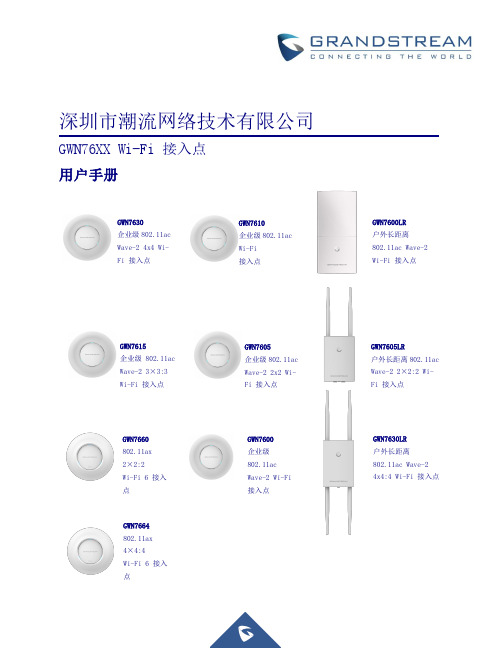
深圳市潮流网络技术有限公司GWN76XX Wi-Fi接入点用户手册GWN7630企业级802.11acWave-24x4Wi-Fi 接入点GWN7615企业级802.11acWave-23×3:3Wi-Fi 接入点GWN7605企业级802.11ac Wave-22x2Wi-Fi 接入点GWN7660802.11ax2×2:2Wi-Fi 6接入点GWN7600企业级802.11ac Wave-2Wi-Fi 接入点GWN7610企业级802.11ac Wi-Fi 接入点GWN7600LR 户外长距离802.11ac Wave-2Wi-Fi 接入点GWN7605LR 户外长距离802.11ac Wave-22×2:2Wi-Fi 接入点GWN7630LR 户外长距离802.11ac Wave-24x4:4Wi-Fi 接入点GWN7664802.11ax4×4:4Wi-Fi 6接入点版权©2020潮流网络技术有限公司.版权所有:未经公司的书面许可,出于任何目的、以任何形式或方式复制或打印的行为是不允许的。
本文中的信息如有改动,恕不另行通知。
最新的电子版本手册可在这里下载:/supportGrandstream是一个注册商标,潮流网络LOGO是潮流网络技术有限公司在美国、欧洲和其它国家的商标。
注意未经潮流批准擅自修改本产品,或以用户手册以外的方式使用本产品,将会导致保修无效。
警告请不要使用与设备不匹配的电源适配器,设备可能因此损坏,导致保修失效。
FCC警告本设备符合FCC规则的第15部分,操作必须符合以下两个条件:(1)此设备不会造成有害干扰。
(2)本设备必须能接受任何干扰,包括可能导致意外操作的干扰。
未经履约方的明确许可而进行的任何更改或修改可能会导致用户失去设备操作权限。
注意:本设备经测试证明符合FCC规则第15部分中关于B类数字设备的限制。
这些限制旨在合理保护用户在住宅安装时免受有害干扰。
中科曙光TC4600刀片服务器用户手册V1.0

商标和版权
“SUGON”及图标是曙先信息产业股份有限公司的商标或注册商标。 “中科曙先”及图标是曙先信息产业股份有限公司的商标或注册商标,文中“曙先信息产业股份有限公司”简称“曙
先公司”。
“AMD”,“Opteron”及图标是 Advanced Micro Devices 公司的注册商标。 “Microsoft”.“Windows”.“Windows Server”及“Windows Server System”是微软公司的商标或注册商标。
如您不正确地或未按本手册的指示和要求安装.使用或保管本产品,或让非曙先公司授权的技术人员修理.变更本产品, 曙先公司将不对由此导致的损害承担任何责任。
本手册中所提供照片.图形.图表和揑图,仅用于解释和说明目的,可能与实际产品有些差别,另外,产品实际觃栺和 配置可能会根据需要不时变更,因此与本手册内容有所不同。请以实际产品为准。
目录
1 2
3
产品简介............................................................................................................. 1
1.1
产品概述 ...................................................................................................................... 1
电气接地要求 服务器必须正确接地,以使其正常运行幵确保安全。必须遵照以下要求安装本设备:任何区域性或国家/地区的电气 连线觃程,如国际电工委员会 (IEC) 觃程 364 第 1 至7 部分。此外,您必须确保安装过程中使用的所有配电设备 (如分支连线和揑座)均为已列出的或经过认证的接地型设备。 由于连在同一电源上的多台服务器需要将大量电流导入地下,因此曙先公司建议所用的 PDU 要么固定地连到建筑 物的分支电路上,要么配装一根连接工业揑头的不可拆卸的电线。那些符合IEC 60309 标准的揑头均视为适用揑头。 建议不要使用普通的电源接线板来连接本服务器。
windows server 2019 安装ca证书格式 -回复
windows server 2019 安装ca证书格式-回复Windows Server 2019 安装CA 证书的格式在Windows Server 2019 上安装CA 证书是一项重要的任务,因为CA 证书用于确保对计算机、网络和互联网资源的身份验证和数据通信的安全性。
CA 证书是一种数字证书,由证书颁发机构(CA)签发和管理。
本文将一步一步回答关于Windows Server 2019 上安装CA 证书格式的问题,以帮助您正确安装和配置CA 证书。
第一步:了解证书格式在安装CA 证书之前,我们需要了解一些常见的证书格式。
以下是几种常见的证书格式:1. X.509 :这是一种最常见的证书格式,常用于Web 服务器和电子邮件服务器证书。
2. PKCS#12:这是一种通用的证书格式,可以包含公钥证书和私钥(私钥加密)。
3. PFX/PKCS#12:这是一种Microsoft 独有的证书格式,通常用于包含公钥证书和私钥(如SSL 证书)。
4. PEM:这是一种基于文本的证书格式,常见于Linux 系统和一些网络设备。
了解不同的证书格式对于选择正确的安装格式至关重要。
在Windows Server 2019 上安装CA 证书,我们将重点讨论PKCS#12/PFX 格式。
第二步:生成CA 证书在安装CA 证书之前,您需要生成CA 证书。
要执行此操作,您可以使用Microsoft 提供的证书服务(Certificate Services)角色或第三方证书颁发机构(CA)。
要使用Microsoft 证书服务生成CA 证书,请执行以下步骤:1. 打开Server Manager 控制台,然后选择"Add Roles and Features"。
2. 在"Select Installation Type" 屏幕上,选择"Role-based or feature-based installation",然后单击"Next"。