P2D243
聚合物锂电池P2D模型的参数辨识方法

设计应用聚合物锂电池P2D模型的参数辨识方法肖席,王建立,阮喻(陆军工程大学通信士官学校,重庆模型的过程参数,在常温25 ℃下设计不同工况进行实验,内阻测试仪测量辨小倍率放电实验辨识电极固相扩散过程相关参数,激励电流实验辨识反应极化和液相扩散过程参数。
经最小二乘拟合相关参数,证明辨识方法可行。
聚合物锂电池;参数辨识;固相扩散Parameter Identification Method for P2D Model of Polymer Lithium BatteryXIAO Xi,WANG Jianli,RUAN YuArmy Engineering University of PLAIn order to identify the parameters of P2D model process of polymer lithium batteryconditions were designed for experiments at normal temperature 25℃,02C small rate dischargediffusion process of the electrode放电充电负极晶体结构正极晶体结构锂离子隔膜锂离子小倍率放电时,近似认为测得的端电压为理想(2)分别为正由于电流较小,忽略极化影响,近似认为:(3)式中,y surf y 0,x 0,为荷电状态。
2.2.2 小倍率放电实验设计在小倍率此时可忽略极化过电势,将式((2)进行求解。
小电流放电测试结果如图测试曲线时间/min500100015002000250030002 400.02 200.02 000.01 800.01 600.01 400.01 200.01 000.0800.0600.0400.0200.00.0电流/mA 容量/mAh图2 0.02 C 放电电压-容量曲线图U p ( y surf )和U n (x surf )对某一特定电极来说是已知的函数,据此可推导E ovc 和(x 0, y 0, 关系,与实测理想电势变化曲线对比并利(x 0, y 0, D 1, D 2, soc )[3]。
PT2432 PT2432A 3 相无传感器无刷直流马达驱动器说明书
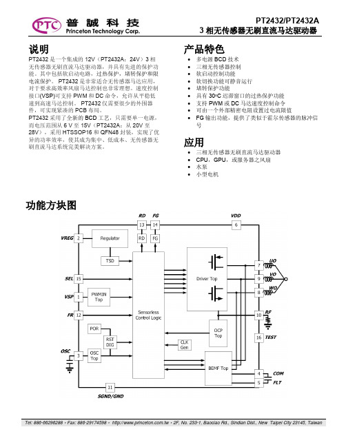
PT2432/PT2432A 3相无传感器无刷直流马达驱动器说明PT2432是一个集成的12V(PT2432A:24V)3相无传感器无刷直流马达驱动器,并具有先进的保护功能。
其中包括软启动电路,过热保护,堵转保护和限电流保护。
PT2432是非常适合无传感器马达应用,对于要求高效率风扇马达控制也非常理想。
速度控制接口(VSP)可支持PWM和DC命令,允许从平稳低速到高速马达控制。
PT2432仅需要很少的外围器件,可实现紧凑的PCB布局。
PT2432采用了全新的BCD工艺,只需要单一电源,而电压范围从6 V至 15V(PT2432A:从20V 至28V),采用HTSSOP16和QFN48封装,实现了优异的功率效率,使其成为集中、低成本、无传感器无刷直流马达系统完美解决方案。
产品特色∙多电源BCD技术∙三相无传感器控制∙软启动控制功能∙软切换功能可静音运行∙堵转保护功能∙具有30o C迟滞窗口的过热保护功能∙支持PWM或DC马达速度控制命令∙可由一个外部精密电阻设置过电流限值∙FG输出功能,提供了类似于霍尔传感器的脉冲信号应用∙三相无传感器无刷直流马达驱动器∙CPU,GPU,或服务器之风扇∙水泵∙小型电机功能方块图HTSSOP16应用电路应用电路组件值表Notes : 1. C2和C3是取决于马达类型.2. R1是取决于马达的应用.QFN48应用线路应用电路组件值表Notes : 1. C3和C4是取决于马达类型.2. R1和R2是取决于马达的应用.HTSSOP16引脚配置引脚说明QFN48引脚配置引脚说明功能說明电源PT2432提供一种内建电压稳压器,除了输出驱动级外,供电给模拟与数字电路区块。
驱动级的负载是马达线圈,呈现电感特性,当马达开始转动,会引导出大电流和尖峰电压。
需要一个合适的旁路电容,并尽可能的放置接近VDD引脚来减少这些尖峰。
此外,加入一个15V(PT2432A:28V)齐纳二极管将帮助抵御从马达反电动势(BEMF)电压。
Motorola 3.5 kHz 产品说明书
RVN4126 3.59100-386-9100-386/T DEVICERVN41772-CD2-3.5MCS/MTSRVN41821-CD2-3.5XTS3000/SABER PORTABLE YES RKN4046KHVN9085 3.51-20 R NO HLN9359 PROG. STAND RVN4057 3.532 X 8 CODEPLUG NO3080385B23 & 5880385B30 MDVN4965 3.59100-WS/T CONFIG KITRVN4053 3.5ASTRO DIGITAL INTERFACE NO3080385B23RVN41842-CD RKN4046A (Portable) 2-3.5ASTRO PORTABLE /MOBILE YES3080369B73 or0180300B10 (Mobile) RVN41831-CD3080369B732-3.5ASTRO SPECTRA MOBILE YES(Low / Mid Power)0180300B10 (High Power) RVN4185CD ASTRO SPECTRA PLUS MOBILE NO MANY OPTIONS; SEESERVICE BRIEF#SB-MO-0101RVN4186CD ASTRO SPECTRA PLUS MANY OPTIONS;MOBILE/PORTABLE COMB SEE SERVICE BRIEF#SB-MO-0101RVN4154 3.5ASTROTAC 3000 COMPAR.3080385B23RVN5003 3.5ASTROTAC COMPARATORS NO3080399E31 Adpt.5880385B34RVN4083 3.5BSC II NO FKN5836ARVN4171 3.5C200RVN4029 3.5CENTRACOM SERIES II NO VARIOUS-SEE MANUAL6881121E49RVN4112 3.5COMMAND PLUS NORVN4149 3.5COMTEGRA YES3082056X02HVN6053CD CT250, 450, 450LS YES AAPMKN4004RVN4079 3.5DESKTRAC CONVENTIONAL YES3080070N01RVN4093 3.5DESKTRAC TRUNKED YES3080070N01RVN4091 3.5DGT 9000 DESKSET YES0180358A22RVN4114 3.5GLOBAL POSITIONING SYS.NO RKN4021AHVN8177 3.5GM/GR300/GR500/GR400M10/M120/130YES3080070N01RVN4159 3.5GP60 SERIES YES PMLN4074AHVN9128 3.5GP300 & GP350RVN4152 3.5GP350 AVSRVN4150 3.5GTX YES HKN9857 (Portable)3080070N01(Mobile) HVN9025CD HT CDM/MTX/EX SERIES YES AARKN4083/AARKN4081RiblessAARKN4075RIBLESS NON-USA RKN4074RVN4098H 3.5HT1000/JT1000-VISAR YES3080371E46(VISAR CONV)RVN4151 3.5HT1000 AVSRVN4098 3.5HT1000/ VISAR CONV’L.YES RKN4035B (HT1000) HVN9084 3.5i750YES HLN-9102ARVN4156 3.5LCS/LTS 2000YES HKN9857(Portable)3080070N01(Mobile) RVN4087 3.5LORAN C LOC. RECV’R.NO RKN4021ARVN4135 3.5M100/M200,M110,M400,R100 includesHVN9173,9177,9646,9774YES3080070N01RVN4023 3.5MARATRAC YES3080070N01RVN4019 3.5MAXTRAC CONVENTIONAL YES3080070N01RVN4139 3.5MAXTRAC LS YES3080070N01RVN4043 3.5MAXTRAC TRK DUPLEX YES3080070N01RVN4178CD MC SERIES, MC2000/2500DDN6124AW/DB25 CONNECTORDDN6367AW/DB9 CONNECTOR RVN41751-CD Rib to MIC connector 1-3.5MCS2000 RKN4062BRVN41131-3.5MCS2000RVN4011 3.5MCX1000YES3000056M01RVN4063 3.5MCX1000 MARINE YES3000056M01RVN4117 3.5MDC/RDLAP DEVICESRVN4105 3.5MOBILE PROG. TOOLRVN4119 3.5MOBITEX DEVICESRVN4128 3.5MPT1327-1200 SERIES YES SEE MANUALRVN4025 3.5MSF5000/PURC/ANALOG YES0180355A30RVN4077 3.5MSF5000/10000FLD YES0180355A30RVN4017K 3.5MT 1000YES RTK4205CRVN4148 3.5MTR 2000YES3082056X02RVN4140 3.5MTRI 2000NORVN41761-CD MTS2000, MT2000*, MTX8000, MTX90001-3.5*programmed by DOS which is included in the RVN4176RVN4131 3.5MTVA CODE PLUG FIXRVN4142 3.5MTVA DOCTOR YES3080070N01RVN4131 3.5MTVA3.EXERVN4013 3.5MTX800 & MTX800S YES RTK4205CRVN4097 1-CD MTX8000/MTX9000,MTS2000,MT2000*,* programmed by DOS which is included in the RVN4176HVN9067CD MTX850/MTX8250MTX950,MTX925RVN4138 3.5MTX-LS YES RKN4035DRVN4035 3.5MX 1000YES RTK4203CRVN4073 3.5MX 800YES RKN4006BHVN9395 P100, P200 LB, P50+, P210, P500, PR3000RVN4134 3.5P100 (HVN9175)P200 LB (HVN9794)P50+ (HVN9395)P210 (HVN9763)P500 (HVN9941)PR3000 (HVN9586)YES RTK4205HVN9852 3.5P110YES HKN9755A/REX1143 HVN9262 3.5P200 UHF/VHF YES RTK4205RVN4129 3.5PDT220YVN4051 3.5PORTABLE REPEATER Portable rptr.P1820/P1821AXRVN4061C 3.5PP 1000/500NO3080385B23 & 5880385B30 RVN5002 3.5QUANTAR/QUANTRO NO3O80369E31RVN4135 3.5R100 (HVN9177)M100/M200/M110/M400YES0180358A52RVN4146 3.5RPM500/660RVN4002 3.5SABER YES RTK4203CRVN4131 3.5SETTLET.EXEHVN9007 3.5SM50 & SM120YESRVN4039 3.5SMART STATUS YES FKN5825AHVN9054 3.5SOFTWARE R03.2 P1225YES3080070N01HVN9001 3.5SOFTWARE R05.00.00 1225LS YES HLN9359AHVN9012 3.5SP50RVN4001N 3.5SPECTRA YES3080369B73 (STANDARD)0180300B10 (HIGH POWER) RVN4099 3.5SPECTRA RAILROAD YES3080369B73RVN4110 3.5STATION ACCESS MODULE NO3080369E31RVN4089A 3.5STX TRANSIT YES0180357A54RVN4051 3.5SYSTEMS SABER YES RTK4203BRVN4075 3.5T5600/T5620 SERIES NO3080385B23HVN9060CD TC3000, TS3000, TR3000RVN4123 3.5VISAR PRIVACY PLUS YES3080371E46FVN4333 3.5VRM 100 TOOLBOX FKN4486A CABLE &ADAPTORRVN4133 3.5VRM 500/600/650/850NORVN4181CD XTS 2500/5000 PORTABLES RKN4105A/RKN4106A RVN41002- 3.5XTS3000 ASTRO PORTABLE/MOBILERVN4170 3.5XTS3500YES RKN4035DRIB SET UPRLN4008E RADIO INTERFACE BOX (RIB)0180357A57RIB AC POWER PACK 120V0180358A56RIB AC POWER PACK 220V3080369B71IBM TO RIB CABLE (25 PIN) (USE WITH XT & PS2)3080369B72IBM TO RIB CABLE (9 PIN)RLN443825 PIN (F) TO 9 PIN (M) ADAPTOR (USE W/3080369B72 FOR AT APPLICATION) 5880385B308 PIN MODULAR TO 25 PIN ”D” ADAPTOR (FOR T5600 ONLY)0180359A29DUPLEX ADAPTOR (MOSTAR/TRAXAR TRNK’D ONLY)Item Disk Radio RIB Cable Number Size Product Required Number Item Disk Radio RIB Cable Number Size Product Required NumberUtilizing your personal computer, Radio Service Software (RSS)/Customer Programming Software (CPS)/CustomerConfiguration Software (CCS) enables you to add or reprogram features/parameters as your requirements change. RSS/CPS/CCS is compatible with IBM XT, AT, PS/2 models 30, 50, 60 and 80.Requires 640K RAM. DOS 3.1 or later. Consult the RSS users guide for the computer configuration and DOS requirements. (ForHT1000, MT/MTS2000, MTX838/8000/9000, Visar and some newer products —IBM model 386, 4 MEG RAM and DOS 5.0 or higher are recommended.) A Radio Interface Box (RIB) may be required as well as the appropriate cables. The RIB and cables must be ordered separately.Licensing:A license is required before a software (RVN) order is placed. The software license is site specific (customer number and ultimate destination tag). All sites/locations must purchase their own software.Be sure to place subsequent orders using the original customer number and ship-to-tag or other licensed sites; ordering software without a licensed customer number and ultimate tag may result in unnecessary delays. To obtain a no charge license agreement kit, order RPX4719. To place an order in the U.S. call 1-800-422-4210. Outside the U.S., FAX 847-576-3023.Subscription Program:The purchase of Radio ServiceSoftware/Customer Programming/Customer ConfigurationSoftware (RVN & HVN kits) entitles the buyer/subscriber to three years of free upgrades. At the end of these three years, the sub-scriber must purchase the same Radio Service Software kit to receive an additional three years of free upgrades. If the sub-scriber does not elect to purchase the same Radio Service Software kit, no upgrades will be sent. Annually a subscription status report is mailed to inform subscribers of the RSS/CPS/CCS items on our database and their expiration dates.Notes:1)A subscription service is offered on “RVN”-Radio Service Software/Customer Programming/Customer Configuration Software kits only.2)“RVN” software must only be procured through Radio Products and Services Division (RPSD). Software not procured through the RPSD will not be recorded on the subscription database; upgrades will not be mailed.3)Upgrades are mailed to the original buyer (customer number & ultimate tag).4)SP software is available through the radio product groups.The Motorola General Radio Service Software Agreement is now available on Motorola Online. If you need assistance please feel free to submit a “Contact Us” or call 800-422-4210.SMART RIB SET UPRLN1015D SMART RIB0180302E27 AC POWER PACK 120V 2580373E86 AC POWER PACK 220V3080390B49SMARTRIB CABLE (9 PIN (F) TO 9 PIN (M) (USE WITH AT)3080390B48SMARTRIB CABLE (25 PIN (F) TO 9 PIN (M) (USE WITH XT)RLN4488ASMART RIB BATTERY PACKWIRELESS DATA GROUP PRODUTS SOFTWARERVN4126 3.59100-386/9100T DEVICES MDVN4965 3.59100-WS/T CONFIG’TN RVN41173.5MDC/RDLAP DEVICESPAGING PRODUCTS MANUALS6881011B54 3.5ADVISOR6881029B90 3.5ADVISOR ELITE 6881023B20 3.5ADVISOR GOLD 6881020B35 3.5ADVISOR PRO FLX 6881032B30 3.5BR8506881032B30 3.5LS3506881032B30 3.5LS5506881032B30 3.5LS7506881033B10 3.5LS9506881035B20 3.5MINITOR III8262947A15 3.5PAGEWRITER 20008262947A15 3.5PAGEWRITER 2000X 6881028B10 3.5TALKABOUT T3406881029B35 3.5TIMEPORT P7308262947A15 3.5TIMEPORT P930NLN3548BUNIVERSAL INTERFACE KITItem Disk Radio NumberSize Product。
安全专业通风试题A答案Word版

华 北 科 技 学 院2009/2010学年第一学期考试试卷(2007 级)考试科目: 矿井通风 选用试卷: A 适用专业: 安全工程(本科)一、填空题(每空1分,共15分)1.煤矿“一通三防”是指通风、瓦斯防治、粉尘防治和火灾防治。
2.煤矿主要通风机附属装置包括风硐、扩散器(塔)、防爆盖(门)和反风装置。
3.在标准状态下,1大气压=760mmHg=10336mmH 2O=101292.8Pa 。
4.《煤矿安全规程规定》,按体积百分比计算,采掘工作面进风流中O 2浓度不得低于20%,CH 4浓度不得超过0.5%,所有作业地点CO 浓度都不得超过0.0024%。
5.在抽出式通风的实验管道中,若在某点测得相对静压为1000Pa ,速压为50 Pa ,则其相对全压为950 Pa ;而在压入式通风的管道中,若在某点测得相对全压为1000Pa ,速压为50 Pa ,则其相对静压为950 Pa 。
二、判断题(对—√,错—×,每小题0.5分,共5分)1.风流总是由绝对静压大的地点向绝对静压小的方向流动。
[ × ] 2.为保证通风机的安全启动,离心式主要通风机应该在其风量尽可能小的状态下启动,而轴流式主要通风机应该在其风量尽可能大的状态下启动: [ √ ]3.严禁1台局部通风机同时向2个作业的掘进工作面通风,但一个掘进工作面可以使用3台以上的局部通风机同时供风,当瓦斯涌出量增加时,还可以增加局部通风机数量,加大掘进工作面的通风能力。
[ × ]4.在同温同压下,大气中相对湿度越高,空气的密度就越小。
[ √ ]5.专用回风巷是指在采区巷道中,专门用于回风,不得用于运料、安设电气设备的巷道。
在有煤与瓦斯突出危险的区域,专用回风巷道还不得行人。
[(部 专业、班级 姓 学密封装订 线√ ]6.在采用压入式通风的掘进巷道中,局部通风机距离回风口的距离不得小于10m。
局部通风机所在巷道的风量不得小于局部通风机的吸风量。
RPI-243;中文规格书,Datasheet资料
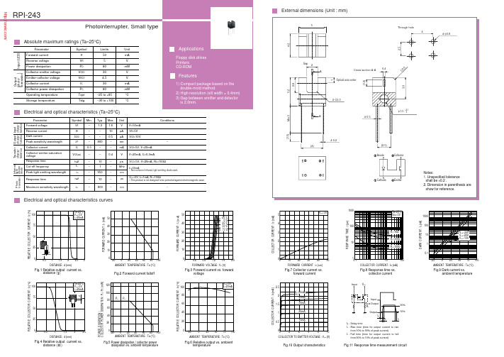
Electrical and optical characteristics (T a =25°C )Electrical and optical characteristics curvesExternal dimensions (Unit : mm)Fig.1 Relative output current vs.distance ( )Fig.4 Relative output current vs.distance ( )R E L A T I V E C O L L E C T O R C U R R E N T : I c (%)DISTANCE : d (mm)R E L A T I V E C O L L E C T O R C U R R E N T : I c (%)DISTANCE : d (mm)Fig.2 Forward current falloffF O R W A R D C U R R E N T : I F (m A )AMBIENT TEMPERATURE : Ta (°C)10504030200Fig.10 Output characteristics C O L L E C T O R C U R R E N T : I c (m A )COLLECTOR TO EMITTER VOLTAGE : V CE (V)Fig.11 Response time measurement circuitt d : t r : t f : Delay timeRise time (time for output current to risefrom 10% to 90% of peak current)Fall time (time for output current to fallfrom 90% to 10% of peak current)Fig.8 Response time vs.collector currentR E S P O N S E T I M E : t (µs )COLLECTOR CURRENT : Ic (mA)Fig.9 Dark current vs.ambient temperatureD A R K C U R RE N T : I D (n A )AMBIENT TEMPERATURE : Ta (°C)Fig.6 Relative output vs. ambienttemperatureR E L A T I V E C O L L E C T O R C U R R E N T : I c (%)AMBIENT TEMPERATURE : Ta (°C)Fig.7 Collector current vs.forward currentC O L L E C T O R C U R R E N T : I c (m A )FORWARD CURRENT : I F (mA )FORWARD VOLTAGE : V F (V ) F O R W A R D C U R R E N T : I F (m A )Fig.3 Forward current vs. forwardvoltageP O W E R D I S S I P A T I O N / C O L L E C T O R P O W E R D I S S I P A T I O N : P D / P c (m W )AMBIENT TEMPERATURE : Ta (°C)Fig.5 Power dissipation / collector powerdissipation vs. ambient temperature −200204060801002080P D P C10012060400AppendixAbout Export Control Order in JapanProducts described herein are the objects of controlled goods in Annex 1 (Item 16) of Export T rade ControlOrder in Japan.In case of export from Japan, please confirm if it applies to "objective" criteria or an "informed" (by MITI clause)on the basis of "catch all controls for Non-Proliferation of Weapons of Mass Destruction.Appendix1-Rev1.1 /分销商库存信息: ROHMRPI-243。
KUTAI ADVR-08 Universal Hybrid Analog-Digital Volt

KUTAI ELECTRONICS INDUSTRY CO., LTD.TEL : +886-7-8121771FAX : +886-7-8121775Website : Headquarters : No.3, Lane 201, Chien Fu St., Chyan Jenn Dist., Kaohsiung 80664, TAIWANADVR-08Universal Hybrid Analog-Digital Voltage Regulator Operation ManualAn Universal Hybrid Analog/Digital 2 lines sensing 8 Amp AVR with multiple power input capability such as Full Harmonic (Compound Windings), Harmonic + Auxiliary Winding, PMG and SHUNT.Compatible with Leroy Somer* R438, R448, R449 and more.Use with KUTAI IVT-1260 / IVT-2460 add-on module can boost generator motor starting capacity.SECTION 1 : SPECIFICATIONSensing Input (E1, E2) Static Power DissipationVoltage 110 - 480 Vac, 1 phase Max.6 watts90 - 130 Vac @ 110 Vac180 - 260 Vac @ 220 Vac Burden in SHUNT & PMG Wiring340 - 520 Vac @ 380 Vac 880 VA @ power input 110 Vac Frequency 50/60 Hz, DIP switch setting 1760 VA @ power input 220 VacPower Input (X1, X2, Aux1)Quadrature Droop Input (S1, S2, S3)Voltage 40 - 300 Vac, 1 phase / 3 phase CT 5A (S1-S2) or 1A (S2-S3) greater than 5VA Frequency 50 - 500 Hz Max. +/- 5% @ P.F +/- 0.71 phase (X1、X2) / 3 phase (X1、X2、Aux1)Analogue Voltage Input (A1, A2)Auxiliary Input (Aux1, Aux2)Input resistance greater than 2K ohmsVoltage 40 - 300 Vac, 1 phase Max. Input +/- 5 VdcFrequency 50 - 500 Hz Sensitivity +/- 25% Generator Volts (adjustable)Excitation Output (F+, F-)Under Frequency Protection (Factory Presets) Voltage Max. 63 Vdc @ power input 110 Vac 50 Hz system presets knee point at 45 HzMax. 125 Vdc @ power input 220 Vac 60 Hz system presets knee point at 55 Hz Current Continuous 8AIntermittent 12A for 10 secs. Over Excitation ProtectionResistance ≧8 ohms @ power input 110 Vac Set point 170 Vdc +/- 5 % @ power input 220 Vac ≧16 ohms @ power input 220 VacFuse Spec. Slow blow 5 x 20mm S505-10A Voltage Thermal DriftLess than 3% at temperature range -40 to +70 ˚C External Voltage Adjustment (VR1, VR2)Max. +/- 4% @ 500 ohms 1 watt potentiometer Under-Frequency Knee Point Thermal DriftMax. +/- 8% @ 1K ohm 1 watt potentiometer Less than +/- 0.1 Hz at -40 to +70 ˚CVoltage Regulation EnvironmentLess than +/- 0.5% ( with 4% engine governing ) Operating T emperature -40 to +70 ˚CStorage T emperature -40 to +85 ˚CBuild Up Voltage Relative Humidity Max. 95%6 Vac 25 Hz residual volts at power input terminal Vibration 3 Gs @ 100 - 2K HzSoft Start Ramp Time Dimensions4 seconds +/- 10% 171.0 (L) x 120.0 (W) x 50.0 (H) mmTypical System Response WeightLess than 20 milliseconds 820 g +/- 2%EMI SuppressionInternal electromagnetic interference filtering___________________________________________________________________________________________ 2ADVR-08SECTION 2 : OUTLINE / SIZE / INSTALLATION REFERENCEFlag Terminal (“Fast-On” terminal)Figure 1Outline Drawing___________________________________________________________________________________________ ADVR-08 3___________________________________________________________________________________________ 4ADVR-08SECTION 3 : DIP SWITCH PROGRAMMING & VR ADJUSTMENTSU/F LEDO/E LEDSet fully50 Hz System : 40 to 51 Hz (Lowest position)60 Hz System : 50 to 61 Hz (Lowest position)(See TRIM)This adjustment allows some control over the generator voltage dip when applying load.It is typically used to compensate for turbo lag, leaving the generator to operate below the UFRO knee point setting. The voltage droop ratio can be set using the DIP adjustment. The range is 10 to 3 V/Hz.HZ HZ___________________________________________________________________________________________ ADVR-085SECTION 4 : WIRING CONNECTIONSExciter fieldPMGS2-S3 N:1AS 2-S 3 N :1AS 1-S 2 N :5A C.T Stator windingsS2-S3 N:1AS1-S2 N:5A Exciter fieldS2-S3 N:1AS1-S2 N:5A C.TFigure 2 Single & Three Phase PMGFigure 3 Three Phase AuxiliaryWinding (Full Harmonic)Figure 4 Auxiliary & HarmonicFigure 5 Self-Excited (SHUNT)Exciter fieldFigure 6ADVR-08 & IVT-1260 / IVT-2460 Wiring Connection※Use only the replacement fuses specified in this user manual.※Appearance and specifications of products are subject to change for improvement without prior notice.___________________________________________________________________________________________ 6ADVR-08。
红外距离传感器产品参考手册说明书

Laser type and high power narrow beam LED type BGS! Types with sensing distances of 100 mm and 300 mm Industry standard sizeHighly accurate height difference detection through low hysteresisRelatedproductsUniversal voltage typeBGS-2VP.384Higher accuracyBGS-HL,BGS-HDLP.310Transparent object detectionZ3R-QP.404 Selection tableFor the connector type, please purchase an optional JCN series connector cable.Options/AccessoriesConnector cablesL-shapedJCN-SCable length: 2 mJCN-5SCable length: 5 mJCN-10SCable length: 10 mJCN-LCable length: 2 mJCN-5LCable length: 5 mJCN-10LCable length: 10 mProtective mounting bracketUltra-durable 2 mm thick typeRust-resistant stainless steelS ensor is firmly secured using M3 Hexsocket head cap screwsT he bracket is also firmly secured usingM6 screwsLK-S01LK-S02 Meander detection of sheet materials Detection of multi-colored trays Detection of items on stainless steel lines Laser type application 1LED type application 1LED type application 2Straight326Laser, standard type BGS-ZL, BGS-Z seriesLaser types (Class 1) and high power narrow beam LED types are availableIdeal for height difference detection using low hysteresisIndustry standard sizeShort-range type hysteresis ≤ 3% (typical value)Mounting hole pitch: 25.4 mmLaser type (equipped with laser OFF input)High power narrow beam LED light source typeThe spot size of the laser type is ø1 mm at 100 mm (short-range type). Optimal for applications that in which small object detection and high repeat accuracy are required. It is also a Class 1 laser in which eye protection for workers is not necessary.*Classified as Class II in the US FDA standards.A short-range type with a sensing distance of 100 mm that achieves a low hysteresis of ≤ 3%. Demonstrates its strength in small height difference detection.* A mid-range type with a sensing distance of 300 mm that achieves a hysteresis of ≤ 5%.Features an industry standard pitch of 25.4 mm.Features a high power narrow beam LED light source . Because the spot light can be seen clearly even in brightfactories regardless of the LED light, confirmation of detection position is easier than for any other conventional model.*Compared to conventional models: Using LED light source.Laser typeH y s t e r e s i s (%)Sensing distance X (mm)High power narrow beam LED typeH y s t e r e s i s (%)Sensing distance X (mm)Laser, standard type BGS-ZL, BGS-Z seriesSpecifications*2. Classified as Class II in the US FDA standards.*3. D efined with center strength 1/e 2 (13.5%). There may be light leakage outside of the specified spot size. The sensor may be affected when there is a highly reflective object close to the target area.*4. Mounting bracket BEF-W100-A is included with the connector type.Specifications are subject to change without prior notice for product improvement purposes.Laser, standard type BGS-ZL, BGS-Z seriesI/O circuit diagramNPN output typePNP output typeConnector typeConnecting1 to 4 are connector pin No.NotesC onnect frame ground to the earth when the switching regulator is used for power supply. B ecause wiring sensor wires with high-voltage wires or power supply wires can result in malfunctions due to noise, which can cause damage, make sure to wire separately. Avoid using the transient state while the power is on (approx. 100 ms). T he connector direction is fixed as in the drawing to the right when you use L-shaped connector cable. Be aware that rotation is not possible.This product emits a Class 1 (II) visible laser beam that is compliant with IEC/JIS, FDA laser safety standards.Warning and explanation labels are affixed to the sides of the sensor.Laser type: BGS-ZL10 /BGS-ZL30Laser light precautions1 10 to 30 VDC2 Laser OFF input (laser type only)3 0 V4 Control output(Pin con guration)Sensor sideConnector cable sideWarningDo not look directly at the laser or intentionally shine the laser beam in another person’s eyes.Laser, standard type BGS-ZL, BGS-Z seriesDimensionsSensorConnector cable (optional)Cable typeConnector typeJCN-S, JCN-5S, JCN-10SJCN-L, JCN-5L, JCN-10L(Unit: mm)Light ON / Dark ONselection switchOutput indicator (orange)Light ON / Dark ONselection switchø4.7, 4-wire × 0.325 mm 2ø4.7, 4-wire × 0.325 mm 2Laser, standard type BGS-ZL, BGS-Z seriesConnector type (when using BEF-W100-A)(Unit: mm)Mounting bracketCable type (when using BEF-W100-B)Laser, standard type BGS-ZL, BGS-Z seriesTypical characteristic dataBGS-ZL10 Laser typeBGS-ZL30 Laser type③S e n s i n g a r e a Y (m m )④③Distance X (mm)④③D i s t a n c eY (m m )④③Sensing distance X (mm)④③Sensing distance (mm)④③Sensing distance (mm)④③H y s t e r e s i s (%)④③S e n s i n g d i s t a n c e (m m )④W h i t e p a p e rB l a c k p a p e rV e n e e b o a r d C a r d b o a r dB l a c k r u b b e rB l a c k s p o n g ③S e n s i n g a r e a Y (m m )④③D i s t a n c e Y(m m )④③H y s t e r e s i s (%)④Hysteresis51002003001015203025③S e n s i n g d i s t a n c e (m m )④③O p t i c a l p l a n e ④③Sensing distance X (mm)④③Sensing distance (mm)④③Distance X (mm)④③Sensing distance (mm)④White paperGray paper/white paper Black paper/white paperW h i t e p a p e rB l a c k p a p e rV e n e e b o a r dC a r d b o a r dB l a c k r u b b e rB l a c k s p o n gLaser, standard type BGS-ZL, BGS-Z seriesBGS-Z10 LED typeBGS-Z30 LED type③S e n s i n g d i s t a n c e (m m )④③S e n s i n g a r e a Y (m m )④③Distance X (mm)④③D i s t a n c e Y (m m )④③Sensing distance X (mm)④③O p t i c a l p l a n e ④③Sensing distance (mm)④③H y s t e r e s i s (%)④③Sensing distance (mm)④W h i t e p a p e rB l a c k p a p e rV e n e e b o a r dC a r d b o a rdB l a c k r u b b e rB l a c k s p o n g③S e n s i n gd i s t a n ce (m m )④③H y s t e r e s i s (%)④③Sensing distance (mm)④③S e n s i n g a r e a Y (m m )④③D i s t a n c e Y (m m )④③Sensing distanceX (mm)④③Distance X (mm)④1020304050③Sensing distance (mm)④③O p t i c a l p l a n e ④5W h i t e p a p e rB l a c k p a p e rV e n e e b o a r dC a r d b o a r dB l a c k r u b b e rB l a c k s p o n g。
74HC243

74HC243Quad bus transceiver; 3-stateRev. 03 — 12 November 2004Product data sheet1.General descriptionThe74HC243is a high-speed Si-gate CMOS device and is pin compatible with low powerSchottky TTL (LSTTL). The 74HC243 is specified in compliance with JEDECstandard no.7A.The 74HC243 is a quad bus transceiver featuring non-inverting 3-state bus compatibleoutputs in both send and receive directions. The 74HC243 is designed for 4-lineasynchronous 2-way data communications between data buses.The output enable inputs (OEA and OEB) can be used to isolate the buses.The 74HC243 is similar to the 74HC242 but has non-inverting (true) outputs.2.Featuress Non-inverting 3-state outputss2-way asynchronous data bus communications Low-power dissipations Complies with JEDEC standard no.7As ESD protection:x HBM EIA/JESD22-A114-B exceeds 2000Vx MM EIA/JESD22-A115-A exceeds 200V.s Multiple package optionss Specified from−40°C to+80°C and from−40°C to+125°C.3.Quick reference data[1]C PD is used to determine the dynamic power dissipation (P D in µW).P D =C PD ×V CC 2×f i ×N +∑(C L ×V CC 2×f o )where:f i =input frequency in MHz;f o =output frequency in MHz;C L =output load capacitance in pF;V CC =supply voltage in V;N =number of inputs switching;∑(C L ×V CC 2×f o )= sum of outputs.4.Ordering informationTable 1:Quick reference data GND =0 V; T amb =25°C; t r =t f =6 ns.Symbol ParameterConditionsMin Typ Max Unit t PHL , t PLH propagation delay An to Bn;Bn to An C L =15 pF; V CC =5 V-6-ns C I input capacitance - 3.5-pF C I/O input/output capacitance -10-pF C PDpower dissipationcapacitance per transceiverV I =GND to V CC[1]-26-pFTable 2:Ordering informationType numberPackageTemperature rangeName DescriptionVersion 74HC243N −40°C to +125°C DIP14plastic dual in-line package; 14leads (300mil)SOT27-174HC243D −40°C to +125°C SO14plastic small outline package; 14leads;body width 3.9mmSOT108-174HC243DB−40°C to +125°CSSOP14plastic shrink small outline package; 14leads;body width 5.3mmSOT337-15.Functional diagramFig 1.Functional diagramFig 2.Logic symbol Fig 3.IEC logic symbol001aab953ENABLE EXITINGOEB OEAA0B0B1A1131110134B2A295B3A386001aab950ENABLE EXITINGOEB OEAA0B0B3A313118136001aab951113EN1121131049586EN26.Pinning information6.1Pinning6.2Pin descriptionFig 4.Pin configuration243OEA V CC n.c.OEB A0n.c.A1B0A2B1A3B2GNDB3001aab9481234567810912111413Table 3:Pin descriptionSymbol Pin DescriptionOEA 1output enable input (active LOW)n.c.2not connected A03data input or output A14data input or output A25data input or output A36data input or output GND 7ground (0 V)B38data output or input B29data output or input B110data output or input B011data output or input n.c.12not connected OEB 13output enable input V CC14positive supply voltage7.Functional description7.1Function table[1]H =HIGH voltage level;L =LOW voltage level;Z =high-impedance OFF-state.8.Limiting values[1]Above 70°C: P tot derates linearly with 12mW/K.[2]Above 70°C: P tot derates linearly with 8mW/K.Table 4:Function table [1]Control Input or outputOEA OEB An Bn L L input B =A H L Z Z L H Z Z HHA =BinputTable 5:Limiting valuesIn accordance with the Absolute Maximum Rating System (IEC 60134). Voltages are referenced to GND (ground = 0 V).Symbol Parameter ConditionsMin Max Unit V CC supply voltage −0.5+7V I IK input diode current V I <−0.5V or V I >V CC +0.5 V -±20mA I OK output diode current V O <−0.5V or V O >V CC +0.5V-±20mA I O output source or sink currentV O =−0.5V to V CC +0.5V-±35mA I CC , I GND V CC or GND current -±70mA T stg storage temperature −65+150°C P totpower dissipation DIP14 package [1]-750mW SO14 and SSOP16packages[2]-500mW9.Recommended operating conditions10.Static characteristicsTable 6:Recommended operating conditions Symbol Parameter ConditionsMin Typ Max Unit V CC supply voltage 2.0 5.0 6.0V V I input voltage 0-V CC V V O output voltage 0-V CC V t r , t finput rise and fall timesV CC = 2.0 V --1000ns V CC = 4.5 V - 6.0500ns V CC = 6.0 V--400ns T ambambient temperature−40-+125°CTable 7:Static characteristicsAt recommended operating conditions; voltages are referenced to GND (ground =0V).Symbol Parameter Conditions Min Typ Max Unit T amb =25°C V IHHIGH-level input voltageV CC =2.0V 1.5 1.2-V V CC =4.5V 3.15 2.4-V V CC =6.0V4.2 3.2-V V ILLOW-level input voltageV CC =2.0V -0.80.5V V CC =4.5V - 2.1 1.35V V CC =6.0V- 2.8 1.8V V OHHIGH-level output voltageV I =V IH or V ILI O =−20µA; V CC =2.0V 1.9 2.0-V I O =−20µA; V CC =4.5V 4.4 4.5-V I O =−20µA; V CC =6.0V 5.9 6.0-V I O =−6.0mA; V CC =4.5V 3.98 4.32-V I O =−7.8mA; V CC =6.0V5.48 5.81-V V OLLOW-level output voltageV I =V IH or V ILI O =20µA; V CC =2.0V -00.1V I O =20µA; V CC =4.5V -00.1V I O =20µA; V CC =6.0V -00.1V I O =6.0mA; V CC =4.5V -0.150.26V I O =7.8mA; V CC =6.0V-0.160.26V I LI input leakage current V I =V CC or GND; V CC =6.0V --±0.1µA I OZ 3-state OFF-state current V I =V IH or V IL ; V CC =6.0V;V O =V CC or GND --±0.5µA I CC quiescent supply current V I =V CC or GND; I O =0A;V CC =6.0V--8.0µA C I input capacitance - 3.5-pF C I/Oinput/output capacitance-10-pFT amb =−40°C to +85°CV IHHIGH-level input voltageV CC =2.0V 1.5--V V CC =4.5V 3.15--V V CC =6.0V4.2--V V ILLOW-level input voltageV CC =2.0V --0.5V V CC =4.5V -- 1.35V V CC =6.0V-- 1.8VV OHHIGH-level output voltageV I =V IH or V ILI O =−20µA; V CC =2.0V 1.9--V I O =−20µA; V CC =4.5V 4.4--V I O =−20µA; V CC =6.0V 5.9--V I O =−6.0mA; V CC =4.5V 3.84--V I O =−7.8mA; V CC =6.0V5.34--VV OLLOW-level output voltageV I =V IH or V ILI O =20µA; V CC =2.0V --0.1V I O =20µA; V CC =4.5V --0.1V I O =20µA; V CC =6.0V --0.1V I O =6.0mA; V CC =4.5V --0.33V I O =7.8mA; V CC =6.0V--0.33V I LI input leakage current V I =V CC or GND; V CC =6.0V --±1.0µA I OZ 3-state OFF-state current V I =V IH or V IL ; V CC =6.0V;V O =V CC or GND --±5.0µA I CCquiescent supply currentV I =V CC or GND; I O =0A;V CC =6.0V --80µAT amb =−40°C to +125°C V IHHIGH-level input voltageV CC =2.0V 1.5--V V CC =4.5V 3.15--V V CC =6.0V4.2--V V ILLOW-level input voltageV CC =2.0V --0.5V V CC =4.5V -- 1.35V V CC =6.0V-- 1.8VV OHHIGH-level output voltageV I =V IH or V IL-I O =−20µA; V CC =2.0V 1.9--V I O =−20µA; V CC =4.5V 4.4--V I O =−20µA; V CC =6.0V 5.9--V I O =−6.0mA; V CC =4.5V 3.7--V I O =−7.8mA; V CC =6.0V5.2--VTable 7:Static characteristics …continuedAt recommended operating conditions; voltages are referenced to GND (ground =0V).Symbol ParameterConditions Min Typ Max Unit11.Dynamic characteristicsV OLLOW-level output voltageV I =V IH or V IL-I O =20µA; V CC =2.0V --0.1V I O =20µA; V CC =4.5V --0.1V I O =20µA; V CC =6.0V --0.1V I O =6.0mA; V CC =4.5V --0.4V I O =7.8mA; V CC =6.0V--0.4V I LI input leakage current V I =V CC or GND; V CC =6.0V --±1.0µA I OZ 3-state OFF-state current V I =V IH or V IL ; V CC =6.0V;V O =V CC or GND --±10.0µA I CCquiescent supply currentV I =V CC or GND; I O =0A;V CC =6.0V--160µATable 7:Static characteristics …continuedAt recommended operating conditions; voltages are referenced to GND (ground =0V).Symbol ParameterConditions MinTyp MaxUnitTable 8:Dynamic characteristicsGND =0 V; t r =t f =6 ns; C L =50 pF; R L =1000Ω; see Figure 8.Symbol Parameter Conditions Min Typ Max UnitT amb = 25°C t PHL , t PLHpropagation delay An to Bn; Bn to Ansee Figure 5V CC = 2.0 V -2290ns V CC = 4.5 V -818ns V CC = 6.0 V-615ns V CC =5.0V;C L =15pF-6-ns t PZH , t PZL3-state output enable time OEA to An or Bn;OEB to An or Bnsee Figure 6 and 7V CC = 2.0 V -50150ns V CC = 4.5 V -1830ns V CC = 6.0 V-1426ns t PHZ , t PLZ3-state output disable time OEA to An or Bn;OEB to An or Bnsee Figure 6 and 7V CC = 2.0 V -61165ns V CC = 4.5 V -2233ns V CC = 6.0 V-1828ns t THL , t TLHoutput transition timesee Figure 5V CC = 2.0 V -1460ns V CC = 4.5 V -512ns V CC = 6.0 V-410ns C PD power dissipation capacitance per transceiver V I =GND to V CC [1]-26-pFT amb =−40°C to +85°Ct PHL , t PLHpropagation delay An to Bn; Bn to Ansee Figure 5V CC = 2.0 V --115ns V CC = 4.5 V --23ns V CC = 6.0 V--20ns[1]C PD is used to determine the dynamic power dissipation (P D in µW).P D =C PD ×V CC 2×f i ×N +∑(C L ×V CC 2×f o )where:f i =input frequency in MHz;f o =output frequency in MHz;C L =output load capacitance in pF;V CC =supply voltage in V;N =number of inputs switching;∑(C L ×V CC 2×f o )= sum of outputs.t PZH , t PZL3-state output enable time OEA to An or Bn;OEB to An or Bnsee Figure 6 and 7V CC = 2.0 V --190ns V CC = 4.5 V --38ns V CC = 6.0 V--33ns t PHZ , t PLZ3-state output disable time OEA to An or Bn;OEB to An or Bnsee Figure 6 and 7V CC = 2.0 V --205ns V CC = 4.5 V --41ns V CC = 6.0 V--35ns t THL , t TLHoutput transition timesee Figure 5V CC = 2.0 V --75ns V CC = 4.5 V --15ns V CC = 6.0 V--13nsT amb =−40°C to +125°C t PHL , t PLHpropagation delay An to Bn; Bn to Ansee Figure 5V CC = 2.0 V --135ns V CC = 4.5 V --27ns V CC = 6.0 V--23ns t PZH , t PZL3-state output enable time OEA to An or Bn;OEB to An or Bnsee Figure 6 and 7V CC = 2.0 V --225ns V CC = 4.5 V --45ns V CC = 6.0 V--38ns t PHZ , t PLZ3-state output disable time OEA to An or Bn;OEB to An or Bnsee Figure 6 and 7V CC = 2.0 V --250ns V CC = 4.5 V --50ns V CC = 6.0 V--43ns t THL , t TLHoutput transition timesee Figure 5V CC = 2.0 V --90ns V CC = 4.5 V --18ns V CC = 6.0 V--15nsTable 8:Dynamic characteristics …continuedGND =0 V; t r =t f =6 ns; C L =50 pF; R L =1000Ω; see Figure 8.Symbol ParameterConditions Min Typ Max Unit12.WaveformsV M = 0.5×V I .Fig 5.Waveforms showing the input (An and Bn) to output (Bn and An) propagationdelays and the output transition timesV M = 0.5×V I .Fig 6.Waveforms showing the 3-state enable and disable times for input OEA001aab955An, Bn inputBn, An outputV Mt PHLt THL t TLHt PLHV MV M OEA inputoutputLOW to OFF OFF to LOWoutputHIGH to OFF OFF to HIGHV M001aab959t ft r90 %10 %t PLZV Mt PZLt PHZt PZH10 %90 %outputs disabledoutputs enabledoutputs enabledV M = 0.5×V I .Fig 7.Waveforms showing the 3-state enable and disable times for input OEBTest data is given in T able 9.Definitions for test circuit:R L = Load resistor.C L = Load capacitance including jig and probe capacitance.R T = Termination resistance should be equal to the output impedance Z o of the pulse generator.Fig 8.Load circuitry for switching times Table 9:Test data Supply Input Load S 1V CC V I t r = t f C L R L t PZL , t PLZ t PZH , t PHZ t PHL , t PLH 2.0 V V CC 6 ns 50 pF 1 k ΩV CC GND open 4.5 V V CC 6 ns 50 pF 1 k ΩV CC GND open 6.0 V V CC 6 ns 50 pF 1 k ΩV CC GND open 5.0 VV CC6 ns15 pF1 k ΩV CCGNDopenV MOEB inputoutputLOW to OFF OFF to LOWoutputHIGH to OFF OFF to HIGHV M001aab956t ft r90 %10 %t PLZV Mt PZLt PHZt PZH10 %90 %outputs disabledoutputs enabledoutputs enabledopen GNDV CC V CCV IV Omna232D.U.T.C LR TR L =1000 ΩPULSE GENERATORS 113.Package outlineFig 9.Package outline SOT27-1 (DIP14)UNIT Amax.12(1)(1)b 1c D (1)Z E e M H L REFERENCESOUTLINE VERSION EUROPEAN PROJECTIONISSUE DATE IEC JEDEC JEITA mm inchesDIMENSIONS (inch dimensions are derived from the original mm dimensions)SOT27-199-12-2703-02-13A min. A max.b max.w M E e 11.731.130.530.380.360.2319.5018.55 6.486.20 3.603.050.2542.547.628.257.8010.08.3 2.24.20.51 3.20.0680.0440.0210.0150.770.730.0140.0090.260.240.140.120.010.10.30.320.310.390.330.0870.170.020.13050G04MO-001SC-501-14M Hc(e )1M EALs e a t i n g p l a n eA 1w Mb 1eDA 2Z14187bEpin 1 index0510 mmscaleNote1. Plastic or metal protrusions of 0.25 mm (0.01 inch) maximum per side are not included.DIP14: plastic dual in-line package; 14 leads (300 mil)SOT27-1Fig 10.Package outline SOT108-1 (SO14)UNIT Amax.A 1A 2A 3b p c D (1)E (1)(1)e H E L L p Q Z y w v θREFERENCESOUTLINE VERSION EUROPEAN PROJECTIONISSUE DATE IEC JEDEC JEITAmminches 1.750.250.101.451.250.250.490.360.250.198.758.554.03.8 1.27 6.25.80.70.60.70.38oo 0.250.1DIMENSIONS (inch dimensions are derived from the original mm dimensions)Note1. Plastic or metal protrusions of 0.15 mm (0.006 inch) maximum per side are not included.1.00.4SOT108-1Xw MθAA 1A 2b pD H EL pQdetail XE Z ecL v M A(A )3A78114y076E06MS-012pin 1 index0.0690.0100.0040.0570.0490.010.0190.0140.01000.00750.350.340.160.150.051.050.0410.2440.2280.0280.0240.0280.0120.010.250.010.0040.0390.01699-12-2703-02-190 2.5 5 mmscaleSO14: plastic small outline package; 14 leads; body width 3.9 mm SOT108-1Fig 11.Package outline SOT337-1 (SSOP14)UNIT A 1A 2A 3b p c D (1)E (1)e H E L L p Q Z y w v θ REFERENCESOUTLINE VERSION EUROPEAN PROJECTIONISSUE DATE IECJEDEC JEITAmm0.210.051.801.650.250.380.250.200.096.46.05.45.20.651.250.27.97.61.030.630.90.71.40.980oo 0.130.1DIMENSIONS (mm are the original dimensions)Note1. Plastic or metal protrusions of 0.25 mm maximum per side are not included.SOT337-199-12-2703-02-19(1)w Mb pD H EE Z ecv M AXAy17148θAA 1A 2L p Qdetail XL(A )3MO-150pin 1 index0 2.5 5 mmscaleSSOP14: plastic shrink small outline package; 14 leads; body width 5.3 mm SOT337-1Amax.214.Revision historyTable 10:Revision historyDocument ID ReleaseData sheet status Change notice Doc. number Supersedesdate74HC243_320041112Product data sheet-9397 750 1380874HC_HCT243_CNV_2 Modifications:•The format of this data sheet has been redesigned to comply with the current presentationand information standard of Philips Semiconductors.•Removed type number 74HCT243.•Inserted family specification.74HC_HCT243_CNV_219970828Product specification--74HC_HCT243_174HC_HCT243_119901201Product specification---15.Data sheet status[1]Please consult the most recently issued data sheet before initiating or completing a design.[2]The product status of the device(s) described in this data sheet may have changed since this data sheet was published. The latest information is available on the Internet at URL .[3]For data sheets describing multiple type numbers, the highest-level product status determines the data sheet status.16.DefinitionsShort-form specification —The data in a short-form specification is extracted from a full data sheet with the same type number and title. For detailed information see the relevant data sheet or data handbook.Limiting values definition — Limiting values given are in accordance with the Absolute Maximum Rating System (IEC 60134). Stress above one or more of the limiting values may cause permanent damage to the device.These are stress ratings only and operation of the device at these or at any other conditions above those given in the Characteristics sections of the specification is not implied. Exposure to limiting values for extended periods may affect device reliability.Application information — Applications that are described herein for any of these products are for illustrative purposes only. Philips Semiconductors make no representation or warranty that such applications will be suitable for the specified use without further testing or modification.17.DisclaimersLife support —These products are not designed for use in life support appliances, devices, or systems where malfunction of these products can reasonably be expected to result in personal injury. Philips Semiconductors customers using or selling these products for use in such applications do so at their own risk and agree to fully indemnify Philips Semiconductors for any damages resulting from such application.Right to make changes —Philips Semiconductors reserves the right to make changes in the products - including circuits, standard cells, and/or software - described or contained herein in order to improve design and/or performance. When the product is in full production (status ‘Production’),relevant changes will be communicated via a Customer Product/Process Change Notification (CPCN). Philips Semiconductors assumes noresponsibility or liability for the use of any of these products, conveys no license or title under any patent, copyright, or mask work right to theseproducts,and makes no representations or warranties that these products are free from patent,copyright,or mask work right infringement,unless otherwise specified.18.Contact informationFor additional information, please visit: For sales office addresses, send an email to: sales.addresses@Level Data sheet status [1]Product status [2][3]DefinitionI Objective data Development This data sheet contains data from the objective specification for product development. Philips Semiconductors reserves the right to change the specification in any manner without notice.IIPreliminary dataQualificationThis data sheet contains data from the preliminary specification.Supplementary data will be published at a later date.Philips Semiconductors reserves the right to change the specification without notice,in order to improve the design and supply the best possible product.III Product data ProductionThis data sheet contains data from the product specification. Philips Semiconductors reserves the right to make changes at any time in order to improve the design,manufacturing and supply.Relevant changes will be communicated via a Customer Product/Process Change Notification (CPCN).19.Contents1General description. . . . . . . . . . . . . . . . . . . . . . 12Features . . . . . . . . . . . . . . . . . . . . . . . . . . . . . . . 13Quick reference data. . . . . . . . . . . . . . . . . . . . . 24Ordering information. . . . . . . . . . . . . . . . . . . . . 25Functional diagram . . . . . . . . . . . . . . . . . . . . . . 36Pinning information. . . . . . . . . . . . . . . . . . . . . . 46.1Pinning . . . . . . . . . . . . . . . . . . . . . . . . . . . . . . . 46.2Pin description . . . . . . . . . . . . . . . . . . . . . . . . . 47Functional description . . . . . . . . . . . . . . . . . . . 57.1Function table. . . . . . . . . . . . . . . . . . . . . . . . . . 58Limiting values. . . . . . . . . . . . . . . . . . . . . . . . . . 59Recommended operating conditions. . . . . . . . 610Static characteristics. . . . . . . . . . . . . . . . . . . . . 611Dynamic characteristics . . . . . . . . . . . . . . . . . . 812Waveforms . . . . . . . . . . . . . . . . . . . . . . . . . . . . 1013Package outline . . . . . . . . . . . . . . . . . . . . . . . . 1214Revision history. . . . . . . . . . . . . . . . . . . . . . . . 1515Data sheet status. . . . . . . . . . . . . . . . . . . . . . . 1616Definitions . . . . . . . . . . . . . . . . . . . . . . . . . . . . 1617Disclaimers. . . . . . . . . . . . . . . . . . . . . . . . . . . . 1618Contact information . . . . . . . . . . . . . . . . . . . . 16© Koninklijke Philips Electronics N.V.2004All rights are reserved.Reproduction in whole or in part is prohibited without the priorwritten consent of the copyright owner.The information presented in this document doesnot form part of any quotation or contract,is believed to be accurate and reliable and maybe changed without notice.No liability will be accepted by the publisher for anyconsequence of its use.Publication thereof does not convey nor imply any license underpatent- or other industrial or intellectual property rights.Date of release: 12 November 2004Document number: 9397 750 13808。
Dupline 字段总线安装总线规格说明书

Du line®Input/Output Specifications•Dupline®- private line modem•Long distance connection of two Dupline®networks•Approved according to EU standard TBR 15•Watchdog output•For mounting on DIN-rail (EN 50022)•LED-indications for Supply, Dupline®and Fail•AC Power SupplyProduct DescriptionDupline® modem for bidirec-tional signal transmission viaowned or rented telephonecables or for installation ofDupline®point to point con-nections over distancesexceeding 10 km.Type Selection Supply SpecificationsSupply Ordering no.Dupline - Private line modem24 VAC G3491 0040 024115 VAC G3491 0040 115230 VAC G3491 0040 230No code module requiredPower supply Overvoltage cat. III (IEC 60664)Rated operational voltagethrough term. 21 & 22 230230 VAC ±15% (IEC 60038)115115 VAC ±15% (IEC 60038)02424 VAC ±15%Frequency45 to 65 HzRated operational power Typ. 3 WPower dissipation≤4 WRated operational withstandvoltage230 4 kV115 2.5 kV024800 VDielectric voltageSupply - Dupline®≥4 kVAC (rms) Private Line ModemType G 3491 0040General SpecificationsSpecifications are subject to change without notice (11.01.2006)1 Dupline®is a registered trademark. A product of the CARLO GAVAZZI GroupDu line®2Specifications are subject to change without notice (11.01.2006)Dupline ®is a registered trademark. A product of the CARLO GAVAZZI GroupWiring DiagramG 3491 0040Mode of OperationThe G 3491 0040 modems connect 2 Dupline ®systems via owned or rented tele-phone cables.T wo private line modems can be used to establish long distance connections betweentwo Dupline ®-systems. A G 3491 0040 must be installed at each end of the line and connected to the owned or leased wire and to the local Dupline ®network. In case of public telephone lines without the need for perma-nent connection, the D 9091modem interface are used together with commonly avail-able modems.G 3491 0040 converts all Dupline ®signals into standard FSK (frequency shift keying)tone signals. These signals can be transmitted via the telephone companies' stan-dard lines/ amplifiers. I n this way Dupline ®signals can be exchanged over very long dis-tances. I n most countries the telephone companies requireauthorization prior to connec-tion of the modem.Each of the Dupline ®instal-lations to be connected must have a channel generator coded for the same number of channels. Even so, one of the two modems is to be set up for master operation and the other one for slave operation (Dip switch 1).When two Dupline ®systems are connected in this way, all channels react as if it were one Dupline ®system. This means that activation of e.g.channel A1 in one system automatically causes channel A1 to be activated in the other system. The modem contains a watchdog output.Any interruption of the Dupline ®or private line leads to com-munication breakdown. As soon as the lines are reestab-lished, communication starts again automatically. The main-tain input is used to define the behaviour of the modem in case of a communication break-down. I f maintain is selected (Dip-Switch 2) the data of the last valid transmission is kept and the channels of the local Dupline ®are controlled accordingly. This conditionremains until communication is reestablished. I f the main-tain input is not activated, all channels controlled from the counterpart system are reset in case of communication break-down.Only two modems (a master and a slave) can be connect-ed to a telephone line. Several modems can, however, be connected to one Dupline ®system.Note : t is recommended to protect the modem by means of external transient protec-tion circuitry.G 3491 0040 also transmit analog values.G 3491 0040 cannot com-municate with FMX 1904.Dip-Switch SettingsSpecifications are subject to change without notice (11.01.2006)3Dupline ®is a registered trademark. A product of the CARLO GAVAZZI GroupDu line®G 3491 0040D I N-rail FMD 411For further information refer to "Accessories".Recommended types:#1 DEHN type VED#2 DEHN type ALE1212228262SupplyLineAccessoriesOperation DiagramRecommended Transient Protection S: signal wireDimensions (mm)。
海康威视 DS-2DP2427ZIXS-DE 440(F0)(P4) 270° Stitched 2

DS-2DP2427ZIXS-DE/440(F0)(P4)270° Stitched 24 MP PanoVu Camera with PTZHikvision DS-2DP2427ZIXS-DE/440(F0)(P4) 270° Stitched 24 MP PanoVu Camera with PTZ is able to capture panoramic images as well as close-up images. The panoramic images are captured by 6 sensors for 270° panorama monitoring. The integration of two cameras can locate the details fast over expansive area. Furthermore, with advanced video analysis and multiple targets tracking algorithms, the PanoVu camera features a wide range of smart functions for multiple targets within the panoramic view, including intrusion detection, line crossing detection, region entrance detection, and region exiting detection. The camera can output alarm signals and link the PTZ for tracking to improve the security efficiency. This product is suitable for the application scenarios that require expansive monitoring and detail capture, such as airports, stations, stadiums, playgrounds, scenic areas, and public squares.⏹High quality imaging with 24 MP resolution, up to 8160 × 2400 @30 fps for panoramic channels⏹Excellent low-light performance with DarkFighter technology⏹40x optical zoom and 16x digital zoom provide close up views over expansive areas⏹Expansive night view with up to 250 m IR distance⏹With one click on the panoramic channel, the PTZ channel shows the details automatically⏹Continous and stable manual tracking, auto-tracking, and panorama tracking⏹Automatic switch between multiple targets⏹Supports 7 alarm inputs, 2 alarm outputs, 1 audio input, and 1 audio outputDORIThe DORI (detect, observe, recognize, identify) distance gives the general idea of the camera ability to distinguish persons or objects within its field of view. It is calculated based on the camera sensor specification and the criteria given by EN 62676-4: 2015.DORI Detect Observe Recognize IdentifyDefinition 25 px/m 63 px/m 125 px/m 250 px/m [Panoramic channel]Distance38.6 m (126.6 ft.) 15.3 m (50.2 ft.) 7.7 m (25.3 ft.) 3.9 m (12.8 ft.)[PTZ channel]Distance (Tele)4137.9 m (13575.8 ft.) 1642.0 m (5387.1 ft.) 827.6 m (2715.2 ft.) 413.8 m (1357.6 ft.)SpecificationCameraImage Sensor [Panoramic channel]: 1/1.8" progressive scan CMOS, [PTZ channel]: 1/1.8" progressive scan CMOSMin. Illumination [Panoramic channel]Color: 0.0005 Lux (F1.0, AGC ON), B/W: 0.0001 Lux (F1.0, AGC ON); [PTZ channel]0.0005 Lux (F1.2, AGC ON), B/W: 0.0001 Lux (F1.2, AGC ON), 0 Lux with IRShutter Speed 1 s to 1/30000 sSlow Shutter YesDay & Night IR cut filterZoom [PTZ channel] 40x optical, 16x digitalMax. Resolution 8160 × 2400LensFocus Auto, semi-auto, manual, rapid focusFocal Length [Panoramic channel] 2.8 mm; [PTZ channel] 6.0 to 240 mmZoom Speed [PTZ channel] Approx. 5.6 sFOV Horizontal FOV 56.6° to 1.8°, vertical FOV 33.7° to 1.0°, diagonal FOV 63.4° to 2.0°Aperture Max. F1.0IlluminatorSupplement Light Type IRSupplement Light Range Up to 250 mSmart Supplement Light YesPTZMovement Range (Pan) 360°Movement Range (Tilt) -15° to 90° (auto flip)Pan Speed Pan speed: configurable from 0.1° to 210°/s; preset speed: 240°/sTilt Speed Tilt speed: configurable from 0.1° to 150°/s, preset speed 200°/sProportional Pan [Panoramic channel]: no; [PTZ channel]: yesPresets 300Patrol Scan 8 patrols, up to 32 presets for each patrolPattern Scan 4 pattern scans, record time over 10 minutes for each scanPower-off Memory YesPark Action Preset, pattern scan, patrol scan, auto scan, tilt scan, random scan, frame scan, panorama scan3D Positioning Yes PTZ Status Display Yes Preset Freezing YesScheduled Task Preset, pattern scan, patrol scan, auto scan, tilt scan, random scan, frame scan, panorama scan, dome reboot, dome adjust, aux outputVideoMain Stream [Panoramic channel]:50 Hz: 25 fps (8160 × 2400, 6120 × 1800, 5760 × 1696, 3840 × 1080), 60 Hz: 30 fps (8160 × 2400, 6120 × 1800, 5760 × 1696, 3840 × 1080); [PTZ channel]:50 Hz: 25 fps (2560 × 1440, 1920 × 1080, 1280 × 960, 1280 × 720) 60 Hz: 30 fps (2560 × 1440, 1920 × 1080, 1280 × 960, 1280 × 720)Sub-Stream [Panoramic channel]:50 Hz: 25 fps (2048 × 600, 1280 × 376)60 Hz: 30 fps (2048 × 600, 1280 × 376); [PTZ channel]:50 Hz: 25 fps (704 × 576, 640 × 480, 352 × 288) 60 Hz: 30 fps (704 × 480, 640 × 480, 352 × 240)Third Stream [Panoramic channel]: no[PTZ channel]:50 Hz: 25 fps (1920 × 1080, 1280 × 960, 1280 × 720, 704 × 576, 640 × 480, 352 × 288) 60 Hz: 30 fps (1920 × 1080, 1280 × 960, 1280 × 720, 704 × 480, 640 × 480, 352 × 240)Video Compression Main stream: H.265+/H.265/H.264+/H.264 Sub-stream: H.265/H.264/MJPEGThird stream: H.265/H.264/MJPEGAudioAudio Compression G.711alaw, G.711ulaw, G.722.1, G.726, MP2L2, AAC, PCMAudio Sampling Rate PCM: 8 kHz, 16 kHz, 32 kHz, 48 kHz; MP2L2: 16 kHz, 32 kHz, 48 kHz; AAC: 16 kHz, 32 kHz, 48 kHzNetworkNetwork Storage NAS (NFS, SMB/CIFS), ANRProtocols IPv4/IPv6, HTTP, HTTPS, 802.1x, QoS, FTP, SMTP, UPnP, SNMP, DNS, DDNS, NTP, RTSP, RTCP, RTP, TCP/IP, UDP, IGMP, ICMP, DHCP, PPPoE, BonjourAPI Open Network Video Interface (Profile S, Profile G, Profile T), ISAPI, SDK, ISUP Simultaneous Live View Up to 20 channelsUser/Host Up to 32 users. 3 user levels: administrator, operator, and userSecurity Authenticated username and password, MAC address binding, HTTPS encryption, 802.1X authenticated access, IP address filterClient iVMS-4200, HikCentral Pro, Hik-Connect Web Browser IE10-11, Chrome 57+, Firefox 52+, Safari 12+ ImageDay/Night Switch Day, night, auto, scheduled-switchImage Enhancement BLC, HLC, 3D DNRWide Dynamic Range (WDR) [Panoramic channel] no, [PTZ channel] 120 dB Defog [Panoramic channel] no; [PTZ channel] optical defog Image Stabilization EISRegional Exposure YesRegional Focus YesImage Settings Saturation, brightness, contrast, sharpness, gain, and white balance adjustable by client software or web browserImage Parameters Switch YesPrivacy Mask Programmable polygon privacy masks (8 for panoramic channel, 24 for PTZ channel), mask color or mosaic configurableSNR ≥ 55 dBInterfaceEthernet Interface 1 RJ45 10M/100M/1000M self-adaptive Ethernet portFiber Optical 1 FC interface, built-in fiber module, 1000M, TX1310/RX1550 nm wavelength, single module fiber, up to 20 km transmission distanceOn-board Storage Built-in memory card slot, support microSD/microSDHC/microSDXC cards, up to 256 GBAlarm 7 alarm inputs, 2 alarm outputsAudio 1 input (line in), max. input amplitude: 2-2.4 vpp, input impedance: 1 KΩ ± 10%; 1 output (line out), line level, output impedance: 600 ΩRS-485 1 RS-485 (Half duplex, HIKVISION, Pelco-P, Pelco-D, self-adaptive) Reset YesEventSmart Event Line crossing detection, region entrance detection, region exiting detection, unattended baggage detection, object removal detection, intrusion detectionSmart Tracking Manual tracking, auto-tracking, panorama tracking. Support patrol tracking among multiple detection scenesAlarm Linkage Upload to FTP/NAS/memory card, notify surveillance center, send email, trigger alarm output, trigger recording, and PTZ actions (such as preset, patrol scan, pattern scan)Deep Learning FunctionFace Capture Detects up to 30 faces simultaneously,Supports detecting, tracking, capturing, grading, selecting of face in motion, and outputs the best face picturePeople Density Supports detecting the level of people density in the configured area Congestion Alarm YesGeneralPower 36 VDC, max. 135 W (including max. 12 W for IR); Hi-PoE, max. 75 W Operating Condition -40°C to 70°C (-40°F to 158 °F). Humidity 90% or less (non-condensing) Wiper NoDemist YesMaterial ADC12Dimension Ø 433.5 mm x 430.4 mm (Ø 17.07" x 16.94")Weight Approx. 18 kg (39.68 lb.)ApprovalSafetyUL (UL 62368-1);CB (IEC 62368-1:2014+A11);CE-LVD (EN 62368-1:2014+A11:2017), BIS (IS 13252(Part 1):2010/IEC 60950-1: 2005); LOA (IEC/EN 60950-1)Environment CE-RoHS (2011/65/EU); WEEE (2012/19/EU); Reach (Regulation (EC) No 1907/2006)ProtectionIP67 Standard, Lightning Protection, Surge Protection and Voltage Transient Protection, ±6kV Line to Gnd, ±3kV Line to Line, IEC61000-4-5, IK10⏹Typical ApplicationHikvision products are classified into three levels according to their anti-corrosion performance. Refer to the following description to choose for your using environment.This model has NO SPECIFIC PROTECTION.LevelDescriptionTop-level protectionHikvision products at this level are equipped for use in areas where professional anti-corrosion protection is a must. Typical application scenarios include coastlines, docks, chemical plants, and more.Moderate protectionHikvision products at this level are equipped for use in areas with moderate anti-corrosion demands. Typical application scenarios include coastal areas about 2 kilometers (1.24 miles) away from coastlines, as well as areas affected by acid rain.No specific protectionHikvision products at this level are equipped for use in areas where no specific anti-corrosion protection is needed.⏹Available ModelDS-2DP2427ZIXS-DE/440(F0)(P4)⏹Dimension⏹Accessory ⏹OptionalDS-1668ZJ-P DS-1668ZJ(20) DS-1603ZJ-Pole-PDS-1603ZJ-P。
高联专题九 排列组合

1981年~2019年全国高中数学联赛试题分类汇编—二项式定理、计数、概率与统计部分第1页共9页高联专题九排列组合、二项式定理、概率2019A 5、在1,2,3,,10 中随机选出一个数a ,在1,2,3,,10 中随机选出一个数b ,则2a b 被3整除的概率为.2019A 8、将6个数2,0,1,9,20,19按任意次序排成一行,拼成一个8位数(首位不为0),则产生的不同的8位数的个数为.2019B 5.将5个数2,0,1,9,2019按任意次序排成一行,拼成一个8位数(首位不为0),则产生的不同的8位数的个数为.2019B 6.设整数4n, 1n x 的展开式中4n x 与xy 两项的系数相等,则n 的值为.2018A 3、将6,5,4,3,2,1随机排成一行,记为f e d c b a ,,,,,,则def abc 是偶数的概率为2018B 3、将6,5,4,3,2,1随机排成一行,记为f e d c b a ,,,,,,则def abc 是奇数的概率为2017A 6、在平面直角坐标系xOy 中,点集 1,0,1,|),( y x y x K ,在K 中随机取出三个点,则这三个点中存在两点距离为5的概率为2017B 6、在平面直角坐标系xOy 中,点集 1,0,1,|),( y x y x K ,在K 中随机取出三个点,则这三个点两两之间距离不超过2的概率为2016A 4、袋子A 中装有2张10元纸币和3张1元纸币,袋子B 中装有4张5元纸币和3张1元纸币,1981年~2019年全国高中数学联赛试题分类汇编—二项式定理、计数、概率与统计部分第2页共9页现随机从两个袋子中各取出两张纸币,则A 中剩下的纸币面值之和大于B 中剩下的纸币面值之和的概率为2016B 5、将红、黄、蓝3个球随机放入5个不同的盒子E D C B A ,,,,中,恰有两个球放在同一盒子的概率为2015A 5、在正方体中随机取3条棱,他们两两异面的概率为2015B 8、正2015边形201521A A A 内接于单位圆O ,任取它的两个不同顶点j i A A ,,1 的概率为2014A 8、设D C B A ,,,是空间四个不共面的点,以21的概率在每对点之间连一条边,任意两对点之间是否连边是相互独立的,则B A ,可用(一条边或者若干条边组成的)空间折线连接的概率为2014B 7、将一副扑克牌中的大小王去掉,在剩下的52张牌中随机地抽取5张,其中至少有两张牌上的数字(或者字母A K Q J ,,,)相同的概率是(要求计算出这个概率的数值,精确到0.001)2013A 6、从20,,2,1 中任取5个不同的数,其中至少有2个是相邻数的概率为2013A 8、已知数列 n a 共有9项,其中101 a a ,且对每个 8,,2,1 i ,均有 21,1,21i i a a 则这样的数列的个数为1981年~2019年全国高中数学联赛试题分类汇编—二项式定理、计数、概率与统计部分第3页共9页2013A 三、(本题满分50分)一次考试共有m 道试题,n 个学生参加,其中2, n m 为给定的整数,每道题的得分规则是:若该题恰有x 个学生没有答对,则每个答对该题的学生得x 分,未答对的学生得0分.每个学生得总分为其m 道题的得分总和.将所有的学生总分从高到低排列为n P P P 21,求21P P 的最大可能值。
稳压二极管型号与电压(Zenerdiodemodelandvoltage)
稳压二极管型号与电压(Zener diode model and voltage)Zener diode model comparison tableAmerican Standard zener diode model1N4727 3V01N4728 3V31N4729 3V61N4730 3V91N4731 4V31N4732 4V71N4733 5V11N4734 5V61N4735 6V21N4736 6V81N4737 7V51N4738 8V21N4739 9V11N4740 10V 1N4741 11V 1N4742 12V 1N4743 13V 1N4744 15V 1N4745 16V 1N4746 18V 1N4747 20V 1N4748 22V 1N4749 24V 1N4750 27V 1N4751 30V 1N4752 33V 1N4753 36V 1N4754 39V 1N4755 43V1N4756 47V1N4757 51VFor specifications, please download them at the following address,/products/Rectifiers/Diode/Zener /Often see a lot of iron encapsulated M written on the board are identified by the regulator, the American Standard 1N series models, there is no specific voltage value, just turn the manual control type and voltage below 3V to the value of the 51V, I hope useful for everyone1N4727 3V01N4728 3V31N4729 3V61N4730 3V91N4731 4V31N4732 4V71N4733 5V11N4734 5V6 1N4735 6V2 1N4736 6V8 1N4737 7V5 1N4738 8V2 1N4739 9V1 1N4740 10V 1N4741 11V 1N4742 12V 1N4743 13V 1N4744 15V 1N4745 16V 1N4746 18V 1N4747 20V 1N4748 22V 1N4749 24V1N4750 27V1N4751 30V1N4752 33V1N4753 36V1N4754 39V1N4755 43V1N4756 47V1N4757 51VDZ is the number of electric regulator, and 1N4148 is similar, in fact 1N4148 is a 0.6V regulator, the regulator is below the corresponding number of voltage value, some small zener voltage standard will directly on the tube body, such as 5V6's 5.6V regulator.1N4728A 3.31N4729A 3.61N4730A 3.91N4731A 4.31N4732A 4.7 1N4733A 5.1 1N4734A 5.6 1N4735A 6.2 1N4736A 6.8 1N4737A 7.5 1N4738A 8.2 1N4739A 9.1 1N4740A 10 1N4741A 11 1N4742A 12 1N4743A 13 1N4744A 15 1N4745A 16 1N4746A 18 1N4747A 201N4748A 221N4749A 241N4750A 271N4751A 301N4752A 331N4753A 361N4754A 391N4755A 431N4756A 471N4757A 511N4758A 561N4759A 621N4760A 681N4761A 75 Motorola IN47 series 1W regulators IN4728 3.3VIN4729 3.6V IN4730 3.9v IN4731 4.3 IN4732 4.7 IN4733 5.1 IN4734 5.6 IN4735 6.2 IN4736 6.8 IN4737 7.5 IN4738 8.2 IN4739 9.1 IN4740 10 IN4741 11 IN4742 12 IN4743 13 IN4744 15IN4745 16IN4746 18IN4747 20IN4748 22IN4749 24IN4750 27IN4751 30IN4752 33IN4753 34IN4754 35IN4755 36IN4756 47IN4757 51Motorola IN52 series 0.5W precision regulator tube IN5226 3.3VIN5227 3.6V IN5228 3.9v IN5229 4.3v IN5230 4.7V IN5231 5.1 IN5232 5.6 IN5233 6IN5234 6.2 IN5235 6.8 IN5236 7.5 IN5237 8.2 IN5238 8.7 IN5239 9.1 IN5240 10 IN5241 11 IN5242 12IN5243 13 IN5244 14 IN5245 15 IN5246 16 IN5247 17 IN5248 18 IN5249 19 IN5250 20 IN5251 22 IN5252 24 IN5253 25 IN5254 27 IN5255 28 IN5256 30 IN5257 33IN5730 5.6 IN5731 6.2 IN5732 6.8 IN5733 7.5 IN5734 8.2 IN5735 9.1 IN5736 10 IN5737 11 IN5738 12 IN5739 13 IN5740 15 IN5741 16 IN5742 18 in5743 20 in5744 22 in5745 24in5746 27 in5747 30 in5748.in5749 36 in5750 39 in5985 2.4. in5986.in5987 3in5988.in5989.in5990.in5991.in5992 4.7 in5993 5.1. in5994 5.6in5995.in5996 6.8in5997 7.5in5998 8.2in5999.in6000 10in6001 11in6002 12in6003 13in6004 15in6005 16in6006 18in6007 20in6008 22贴片型sod - 123穏压二极管型号规格标示法sinloon marking codesmd zener diode sod.型号电压代码标示type / voltage / marking code hzd5221b 2.4v z21hzd5222b 2.5v z22hzd5223b 2.7v z23hzd5224b 2.8v z24hzd5225b 3.0v z25hzd5226b 3.3v z26hzd5227b 3.6v z27hzd5228b 3.9v z28hzd5229b 4.3v z29hzd5230b 4.7v z30hzd5231b 5.1v z31hzd5232b 5.6v z32hzd5233b 6.0v z33hzd5234b 6.2v z34hzd5235b 6.8v z35hzd5236b 7.5v z36hzd5237b 8.2v z37hzd5238b 8.7v z38hzd5239b 9.1v z39z40 hzd5240b 10vhzd5241b 11v z41z42 hzd5242b 12vz43 hzd5243b 13vz44 hzd5244b 14vz45常用稳压ic大全 hzd5245b 15v 正5v稳压器 7805 (1a).正6v稳压器 7806 (1a).正8v稳压器 7808 (1a).正9v稳压议 7809 (1a).7812 正12v稳压器 (1a).正15v稳压器 7815 (1a).正18v稳压器 7818 (1a).正24v稳压器 7824 (1a).* * * * * * * * * * * * * * * * * * * * * * * * * * * * * * * * * * * * * * *78l05 正5v稳压器 (100ma)78l06 正6v稳压器 (100ma)78l08 正8v稳压器 (100ma)78l09 正9v稳压器 (100ma)78l12 正12v稳压器 (100ma)78l15 正15v稳压器 (100ma)78l18 正18v稳压器 (100ma)78l24 正24v稳压器 (100ma)* * * * * * * * * * * * * * * * * * * * * * * * * * * * * * * * * * * * * * *7905 负5v稳压器 (1a).负6v稳压器 30 7658 (1a).7908 负8v稳压器 (1a).7909 负9v稳压器 (1a).7912 负12v稳压器 (1a).负15v稳压器 7915 (1a).(1) 负18v稳压器 79187924 负24v稳压器 (1a).* * * * * * * * * * * * * * * * * * * * * * * * * * * * * * * * * * * * * * *79l05 负5v稳压器 (100ma)79l06 负6v稳压器 (100ma)79l08 负8v稳压器 (100ma)79l09 负9v稳压器 (100ma)79l12 负12v稳压器 (100ma)79l15 负15v稳压器 (100ma)79l18 负18v稳压器 (100ma)79l24 负24v稳压器 (100ma)* * * * * * * * * * * * * * * * * * * * * * * * * * * * * * * * * * * * * * *lm1575t - 3.3 3.3v简易开关电源稳压器 (1a)lm1575t - 5.0 5v简易开关电源稳压器 (1a).lm1575t - 12 12v简易开关电源稳压器 (1a)lm1575t 15 15v简易开关电源稳压器 (1a)lm1575t - wo 简易开关电源稳压器 (1a可调 23 to 37)lm1575hvt - 3.3 3.3v简易开关电源稳压器 (1a)lm1575hvt - 5.0 5v简易开关电源稳压器 (1a).lm1575hvt - 12 12v简易开关电源稳压器 (1a)lm1575hvt 15 15v简易开关电源稳压器 (1a)lm1575hvt - wo 简易开关电源稳压器 (1a可调 23 to 37)* * * * * * * * * * * * * * * * * * * * * * * * * * * * * * * * * * * * * *lm2575t - 3.3 3.3v简易开关电源稳压器 (1a)lm2575t - 5.0 5v简易开关电源稳压器 (1a).lm2575t - 12 12v简易开关电源稳压器 (1a)lm2575t 15 15v简易开关电源稳压器 (1a)lm2575t - wo 简易开关电源稳压器 (1a可调 23 to 37)lm2575hvt - 3.3 3.3v简易开关电源稳压器 (1a)lm2575hvt - 5.0 5v简易开关电源稳压器 (1a).LM2575HVT-12 12V simple switching power supply regulator (1A)LM2575HVT-15 15V simple switching power supply regulator (1A)LM2575HVT-ADJ simple switching power supply regulator (1A adjustable 1.23 to 37)**************************************LM2576T-3.3 3.3V simple switching power supply regulator (3A)LM2576T-5.0 5.0V simple switching power supply regulator (3A)LM2576T-12 12V simple switching power supply regulator (3A)LM2576T-15 15V simple switching power supply regulator (3A)LM2576T-ADJ simple switching power supply regulator (3A adjustable 1.23V, to, 37V)LM2576HVT-3.3 3.3V simple switching power supply regulator (3A)LM2576HVT-5.0 5.0V simple switching power supply regulator (3A)LM2576HVT-12 12V simple switching power supply regulator (3A) LM2576HVT-15 15V simple switching power supply regulator (3A)LM2576HVT-ADJ simple switching power supply regulator (3A adjustable 1.23V, to, 37V)**************************************LM2930T-5.0 5.0V low dropout voltage regulatorLM2930T-8.0 8.0V low dropout voltage regulatorLM2931AZ-5.0 5.0V low dropout voltage regulator (TO-92)LM2931T-5.0 5.0V low dropout voltage regulatorLM2931CT 3V to 29V low dropout voltage regulator (TO-220,5PIN)LM2940CT-5.0 5.0V low dropout voltage regulatorLM2940CT-8.0 8.0V low dropout voltage regulatorLM2940CT-9.0 9.0V low dropout voltage regulatorLM2940CT-10 10V low dropout voltage regulatorLM2940CT-12 12V low dropout voltage regulatorLM2940CT-15 15V low dropout voltage regulator**************************************LM123K 5V regulator (3A)LM323K 5V regulator (3A)LM117K 1.2V to 37V three adjustable regulator (1.5A) LM317LZ 1.2V to 37V three adjustable regulator (0.1A) LM317T 1.2V to 37V three adjustable regulator (1.5A) LM317K 1.2V to 37V three adjustable regulator (1.5A)LM133K three terminal adjustable -1.2V to -37V voltage regulator (3.0A)LM333K three terminal adjustable -1.2V to -37V voltage regulator (3.0A)LM337K three terminal adjustable -1.2V to -37V voltage regulator (1.5A)LM337T three terminal adjustable -1.2V to -37V voltage regulator (1.5A)LM337LZ three terminal adjustable -1.2V to -37V voltage regulator (0.1A)LM150K three terminal adjustable 1.2V to 32V voltage regulator (3A)LM350K three terminal adjustable 1.2V to 32V voltage regulator (3A)LM350T three terminal adjustable 1.2V to 32V voltage regulator (3A)LM138K three adjustable 1.2V to 32V regulator (5A)LM338T three adjustable 1.2V to 32V regulator (5A)LM338K three adjustable 1.2V to 32V regulator (5A)LM336-2.5 2.5V precision reference voltage sourceLM336-5.0 5.0V precision reference voltage sourceLM385-1.2 1.2V precision reference voltage sourceLM385-2.5 2.5V precision reference voltage sourceLM399H 6.9999V precision reference voltage sourceLM431ACZ precision adjustable 2.5V to 36V reference regulator LM723 high precision adjustable 2V to 37V regulatorLM105 high precision adjustable 4.5V to 40V regulatorLM305 high precision adjustable 4.5V to40V regulatorMC1403 2.5V reference voltage sourceMC34063 DC-DC DC converterSG3524 PWM switching power supply controllerTL431 precision adjustable 2.5V to 36V reference regulator TL494 PWM switching power supply controllerTL497 frequency modulation switching power supply controller TL7705 battery powered / undervoltage controller。
总需求与总供给曲线

4
2)实际余额效应:价格水平上升,使人 实际余额效应:价格水平上升, 们持有的货币及其固定价值资产的实 际价值降低,人们变得更穷,消费水 际价值降低,人们变得更穷, 平减少,此效应称为实际余额效应。 平减少,此效应称为实际余额效应。 3)价格水平上升使人们的名义收入增加, 价格水平上升使人们的名义收入增加, 从而税负增加,可支配收入减少,进 从而税负增加,可支配收入减少, 而消费水平下降。 而消费水平下降。
28
2、 凯恩斯总供给曲线
P 潜在产量 前提:《通论》 前提:《通论》 :《通论 的背景。 的背景。 形成原因:工资 形成原因: 和价格具有刚性; 和价格具有刚性; 短期中W 短期中W和P没 有足够时间调整。 有足够时间调整。 y
P0
0
凯恩斯总供给曲线
29
原因
Ns>Nd 企业遵循合同,W不变; 企业遵循合同, 不变; 货币工资受劳动合同约束。 货币工资受劳动合同约束。 Ns<Nd 工人遵循合同,W不变。 工人遵循合同, 不变。
P
0
yf
y
27
原因:(1)货币工资W和价格水平P :(1 货币工资W和价格水平P 原因:( 可以迅速或立即自行调节; 可以迅速或立即自行调节;
货币工资具有充分弹性。 货币工资具有充分弹性。 Ns>Nd W ↓ ; Ns<Nd W ↑
(2)长期中货币工资W和价 长期中货币工资W 格水平P有充分的时间进行调整,使实 格水平P有充分的时间进行调整, 际工资处于充分就业应有的水平。 际工资处于充分就业应有的水平。
SAE AMS2432D

__________________________________________________________________________________________________________________________________________ SAE Technical Standards Board Rules provide that: “This report is published by SAE to advance the state of technical and engineering sciences. The use of this report is entirely voluntary, and its applicability and suitability for any particular use, including any patent infringement arising therefrom, is the sole responsibility of the user.” SAE reviews each technical report at least every five years at which time it may be reaffirmed, revised, or cancelled. SAE invites your written comments and suggestions. Copyright © 2012 SAE InternationalAll rights reserved. No part of this publication may be reproduced, stored in a retrieval system or transmitted, in any form or by any means, electronic, mechanical, photocopying, recording, or otherwise, without the prior written permission of SAE. TO PLACE A DOCUMENT ORDER: Tel: 877-606-7323 (inside USA and Canada) Tel: +1 724-776-4970 (outside USA) Fax: 724-776-0790Email: CustomerService@ SAE WEB ADDRESS:h ttp://SAE values your input. To provide feedback on this Technical Report, please visit/technical/standards/AMS4988BAEROSPACE MATERIALSPECIFICATIONAMS2432REV. DIssued 1990-01 Reaffirmed 2010-05 Revised 2013-02Superseding AMS2432C(R) Shot Peening, Computer MonitoredRATIONALEThis revision was issued as part of the SAE Five Year Review process and standardizes shot peening with AMS2430 and industry practices.NOTICEORDERING INFORMATION: 1) The following information should be provided to the shot peen processor by the purchaser. If the purchaser does notprovide any of the following, the processor shall use the specification provisions herein.a. Purchase order number and revision levelb. Part number and revision levelc. Part alloy and tensile strength and/or hardnessd.Quantity of parts e. AMS2432D f. Media type, hardness, size in accordance with AMS2431. See 3.5. g. Test strip type. See 3.2.2. h. Pre-shot peen cleaning method. See 3.3. i. Intensity requirement. See 3.5 and 3.6. j. Intensity verification locations. See 3.5. k. C overage requirement. See 3.6. l. C overage verification method and if use of fluorescent tracer or dye marker inks requires cognizant engineeringorganization approval. See 3.6 and 4.2.1.1. m. Part locations to be shot peened, free from peening, or peening optional. See 3.6. n. If externally applied forces are permitted on part during processing. See 3.5. o. If purchaser requires approval of the processor’s shot peening parameter sheet(s). See 3.7 and 4.3.2. p. I f purchaser allows the use of alternative intensity verification methods. See 3.7 and 3.8.1 q. Post-shot peen cleaning method: include instruction and procedure to remove iron contamination, if applicable, andif purchaser requires peening processor to perform this operation. See 3.9. r. Part preservation/shipping method. See 3.9 and 5. 1. SCOPE 1.1PurposeThis specification establishes the requirements for computer monitored shot peening of part surfaces by impingement of media, including metallic, glass, or ceramic shot. Computer monitored peening is intended to provide a method of process observation, traceability, and response for all process input settings, in real time, during the entire peening process to ensure with objective evidence, the desired process outputs. Shot peening in accordance with AMS2432 meets or exceeds the requirements of AMS2430.1.2 ApplicationShot peening is typically used to induce residual compressive stress in the surface layers of parts, and may be used to increase fatigue strength and resistance to stress-corrosion cracking. Shot peening with computer monitoring is typically used to provide control of the peening process to ensure consistent, repetitive peening coverage and intensity on parts. Computer monitored processing is typically required so that the traceability steps specified herein can be utilized by the design authority to take full credit for the benefits of shot peening in the design life.1.2.1 Related peening processes, such as tumble peening, slurry peening, manual peening, peen forming andstraightening, peening for prevention of intergranular corrosion, and peening to produce a surface texture, are beyond the scope of this specification.2. APPLICABLE DOCUMENTSThe issue of the following documents in effect on the date of the purchase order forms a part of this specification to the extent specified herein. The processor may work to a subsequent revision of a document unless a specific document issue is specified. When the referenced document has been cancelled and no superseding document has been specified, the last published issue of that document shall apply.2.1 SAE PublicationsAvailable from SAE International, 400 Commonwealth Drive, Warrendale, PA 15096-0001, Tel: 877-606-7323 (inside USA and Canada) or 724-776-4970 (outside USA), .AMS2431 Peening Media, General RequirementsAMS2430 Shot Peening, AutomaticSAE J442 Test Strip, Holder, and Gage for Shot PeeningSAE J443 Procedures for Using Standard Shot Peening Almen StripSAE J2277 Shot Peening Coverage Determination2.2 ASTM PublicationsAvailable from ASTM International, 100 Barr Harbor Drive, P.O. Box C700, West Conshohocken, PA 19428-2959, Tel: 610-832-9585, .ASTM E 18 Rockwell Hardness and Rockwell Superficial Hardness of Metallic Materials2.3 ISO PublicationsAvailable from International Organization for Standardization, 1, rue de Varembe, Casa postale 56, CH-1211 Geneva 20, Switzerland, Tel. +41 22 749 01 11, .ISO-10012 Measurement Management Systems3. TECHNICAL REQUIREMENTSThe AMS2430 Shot Peening, Automatic specification provides the base requirements for the shot peening provided in this specification and is referenced throughout this document. When the AMS2432 computer monitored shot peening process differs from the AMS2430 process, there are additional requirements listed in this specification. Throughout this document, the acronym “IAW” is used for the meaning: “in accordance with.”3.1 Peening Media: New and in-process media shall be IAW AMS2430.3.2 Equipment and Materials3.2.1 P eening Machine3.2.1.1 The peening machine shall run automatically and may be computer controlled. Peening machines shall beequipped with computers for continuously monitoring and recording the parameters shown in Table 1 within the tolerance indicated. Recording shall be digitally recorded or in hard copy and retained in accordance with 4.4.The machine shall provide a means of propelling, at a controlled rate, dry media with air pressure against the part. Alternatively, metallic media may be propelled by centrifugal force. The machine shall provide a means of moving, at a uniform speed, either the part through the media stream or the media stream over the part in either translation, rotation, or both, as required. The part shall not be subjected to any random movement during the process. The machine shall be capable of consistently reproducing the required shot peening intensities.TABLE 1 - PARAMETERS FOR PEENING MACHINESParameter Units Process Tolerances Shutdown LimitsPlus or MinusShot Flow (for each nozzle) Pounds/minute(kg/minute)10%Air PressureNOTE 1 (for each nozzle) psi (kPa) > 20 psi 10%≤ 20 psi 20%Wheel Speed (for each wheel) rpm > 2000 rpm 1%< 2000 rpm 20 rpmNozzle or Wheel TranslationSpeed Inch/minute(mm/minute)10%Deflector Speed Inch/minute(mm/minute)10%Nozzle and/orWheel ShutDownSeconds 1Turntable Speed rpm 10% Part Speed rpm/inch/minute(mm/minute)10%Conveyor Speed Inch/Minute(mm/minute)10%Peening CycleTimeSeconds 1Nozzle/Wheel Position Inch/degree(mm/degree)0.062 inch (1.57 mm)/ 5 degreesTable/Part Indexing Inch/degree(mm/degree)0.062 inch (1.57 mm)/ 5 degreesNOTE 1: On direct pressure and suction systems, air pressure shall be measured at or as close as practical to the nozzle. For gravity type systems, air pressure should be measured down stream of regulator for each nozzle. All gages shall be labeled in accordance with ISO 10012.3.2.1.2 The peening system shall be capable of interrupting the peening cycle within one second, when excursionsoutside set tolerances are detected for shot flow, air pressure, wheel speed, nozzle and/or wheel translation speed, turntable speed, part speed, or conveyor speed. Excursions outside the limits in Table 1 shall cause an aborted cycle and the computer system shall record the time and abort details for the parameters listed in Table1. Notation of root cause and corrective action shall be documented. Restarting of the machine shall only bedone by authorized personnel. After the out-of-tolerance condition has been corrected, the peening system shall be able to resume operations to complete the balance of the process cycle from the position of shut-down, or restart program from the beginning, Parts processed during to an aborted cycle shall be so identified on the peening certificate and/or computer print-out.3.2.1.3 The machine shall incorporate equipment to extract dust and fine particle contaminants from the in-processmedia unless the purchaser permits its absence. Peening machine shall be equipped with a shot screening system and shot shape control mechanisms capable of continuously maintaining the quality of the peening media in the machine to meet the requirements of 3.1.3.2.2 Test StripsAlmen test strips shall conform to SAE J442 except thickness and flatness tolerance shall be ±0.0005 inch (±0.013mm). Mechanically deforming strips to meet the prebow requirement is not permitted. Usage shall conform to SAE J443.3.2.2.1 Hardness shall be 73.0 to 74.5 HRA for N strips and 45 to 48 HRC, or equivalent, for other standard strips.Hardness shall be measured in accordance with ASTM E 18 at approximately 0.5 inch (12.7 mm) from either end on the longitudinal center line of a flat side using Rockwell "C" scale, or equivalent, for A and C strips. For N strips, the Rockwell "A" scale, or equivalent, shall be used. Sampling for hardness testing of the strips may be used to minimize hardness tester impressions on the strips.3.2.2.2 Subsize or otherwise standard shaded or masked test strips shall be in accordance with AMS2430.3.2.3 GageAlmen test gages used with standard test strips shall conform to SAE J442 with end stops except that the gages shall have digital readout and have an accuracy of ±0.0001 inch (±0.0025 mm). Almen gages shall be zeroed, at a minimum, once daily using a zero block that is flat within 0.0002 inch (0.005 mm). Gages of appropriate design shall be used for arc height measurements of subsized strips.3.2.4 T est Strip HolderAlmen test strip holder shall be in accordance with SAE J442.3.2.5 Almen Test Strip FixtureA test strip fixture will be made from either a scrap part or a representative non-adjustable fixture fitted with test strip holder(s) to mount the test strip(s) for use during the intensity development or intensity verification in accordance with SAE J443. If test strip holders for masked test strips are used, they shall be approved by the cognizant engineering organization. The Almen test strip fixture shall represent the surface to be peened and be rotated or translated in the same manner as the part during the peening process. The design of the Almen strip fixture shall be approved by the cognizant engineering organization. The fixture shall be numbered and recorded in the procedure sheet and shall be used for all subsequent intensity verifications3.2.6 Machine Verification ToolFor machines that are computer controlled and monitored in accordance with AMS 2432, a machine verification tool is an Almen test strip holder designed to establish process intensity baselines. The tool shall also be used to verify consistent machine performance relative to the baseline during production. The machine verification tool shall be documented on the process parameter sheet and its design and use shall be approved by the cognizant engineering organization.3.2.7 Nozzle Holding FixtureWhen a non-robotic air nozzle peening machine is used, each nozzle shall be held in a fixture so that the angle of impingement and stand-off distance conforms to the process parameter sheet during peening. The nozzle holding fixture, when used, shall be numbered and recorded on the process parameter sheet.3.2.8 Control CageWhen a centrifugal wheel machine is used, the control cage, which regulates the position and angle of the maximum intensity zone generated by the wheel, shall be set in respect to the part location, so that the angle of impingement of the maximum intensity zone will remain constant to procedure sheet requirements. A reference point on the impeller cage position indicator shall be part of the wheel system. The position of the control cage shall be recorded on the procedure sheet.3.2.9 M edia size inspection equipmentIAW AMS2430.3.2.10 Media shape inspection equipmentIAW AMS2430.3.3 Prepeening PreparationIAW AMS2430.3.4 MaskingAreas of the part that are designated to be free from any shot peening shall be suitably masked or protected from the peening stream. Unless otherwise specified, the variation in boundaries of the areas to be peened, when limited, shall be -0 to + 0.125 inch (-0 to +3.18 mm).3.5 PeeningIAW AMS2430 and the following:3.5.1 Shot peening locations used for intensity verification (Almen test strip locations), media type, media size andpeening intensities shall be as specified by the drawing or established by the cognizant engineering organization. If media size and intensity are not specified, reference the guidelines provided in Table 2. The resulting parameters for process control shall be documented in accordance with 3.7.3.TABLE 2 - MEDIA SIZE AND INTENSITY GUIDELINES FOR VARIOUS MATERIALSMaterial Thickness 0.090 to 0.375 inch (2.29 to 9.52 mm)Material Thickness Over 0.375 inch (9.52 mm)Material Shot Size Intensity, inch (mm) Shot Size Intensity, inch (mm)Titanium Alloys 110, 170 0.006 to 0.010A(0.15 to 0.25A) 110, 170 0.006 to 0.010A(0.15 to 0.25A)Steel,tensile strength less than 200 ksi (less than 1379 MPa) 230, 330 0.008 to 0.012A(0.20 to 0.30A)230, 330 0.010 to 0.014A(0.25 to 0.36A)Steel,tensile strength 200 to 260 ksi (1379 to 1793 MPa) 170, 230 0.008 to 0.012A(0.20 to 0.30A)230, 330 0.012 to 0.016A(0.30 to 0.41A)Aluminum 170, 230 0.006 to 0.010A(0.15 to 0.25A) 230, 330 0.010 to 0.014A(0.25 to 0.36A)Holes: Aluminum alloys under 0.750 inch (19.05 mm) diameter 70, 130 0.010 to 0.015N(0.25 to 0.38N) -- --Holes: All other alloys except aluminumunder 0.750 inch(19.05 mm) diameter 70, 110 0.010 to 0.015N(0.25 to 0.38N) -- --General Notes:1. Shot size and intensity specified on the part drawing shall take precedence.2. Shot sizes listed in Table 2 are for ASR (cast steel shot, regular) and ASH (cast steel shot, hard). Equivalent sizesof other media, in accordance with AMS 2431, shall be used when shown on part drawing.3. For material thickness under 0.090 inch (2.29 mm), see 3.6.2.3.3.6 Shot Peening Properties (including intensity and coverage requirements)Shall be in accordance with AMS2430 and the following:3.6.1 A t no time can the test strip arc height measurements during intensity verification fall below the minimum intensityrequirement specified on the engineering drawing .3.6.2 Application to Specific GeometriesIAW AMS2430 and the following.3.6.2.1 When media size is not specified and two or more thicknesses are present on the same part and one is over0.375 inch (9.52 mm) and the other is equal to or less than 0.375 inch (9.52 mm) (see Table 2), the part shall bepeened as follows, or as otherwise approved by the cognizant engineering organization.3.6.2.1.1 The thicker area shall be peened using the correct shot size and intensity for that thickness.3.6.2.1.2 The thinner areas shall be masked at any outside corner where the change of cross-section occurs. Do notmask on an inside radius. If the change of cross-section is gradual, the peening intensity and coverage shall fade within 2.0 inches (51 mm) into the thinner area.3.6.2.1.3 The thinner areas shall next be peened to the correct intensity and shot size with no masking of thickersections, except as required by the drawing. Full coverage with this second shot size and intensity is requiredfor not less than a 2.0 inch (51 mm) overlap into the area previously peened, or to the limit of the previouslypeened area if it less than 2.0 inch.3.6.2.2 Peening is optional on inside surfaces of holes and apertures under 0.125 inch (3.18 mm) diameter or width.Peening is optional in blind holes and recesses under 0.5 inch (13 mm) in diameter or width, if depth exceeds diameter or width. Ricochet peening may be used if permitted by the cognizant engineering organization.3.6.2.3 Thin sections under 0.090 inch (2.29 mm) in nominal thickness shall not be peened unless specifically requiredon the drawing. When peening is required, shot size, intensity, and coverage shall be specified on the drawing. 3.7 Process Parameter SheetIAW AMS2430 and the following:3.7.1 Process developmentIAW AMS2430.3.7.2 Shutdown limits for air pressure and shot flow shall be refined during procedure development to ensureconformance to drawing intensity requirements. To establish shutdown limits, two arc height tests shall be conducted at the intensity time, one at a high air pressure limit/low shot flow combination and the other at a low air pressure limit/high shot flow combination. The air pressure and shot flow shutdown limits shall be adjusted until these arc heights are within drawing intensity range and then documented on the process parameter sheet.3.7.3 All shot peening process parameter sheets shall include figures showing the machine and fixture set up withnozzle/wheel relation to the fixture/part and shall document the process parameters shown in Table 3 at minimum:TABLE 3 - PROCESS PARAMETER SHEET REQUIREMENTSProcess parameter sheet number and datePurchaser approval date (if required)Part number (drawing) revision and datePart material and tensile strength and/or hardnessAMS2432Intensity requirementTest strip type (N, A, C) and/or subsize strip information if applicablePart locations to be shot peened, free from peening, or peening optionalPercent coverage requirementMedia type, hardness, size in accordance with AMS2431Type of machineMachine number or serial numberNumber of nozzles or wheelsSize of nozzles or wheelsSize of metering orifice (pneumatic machine only, if metered)Nozzle or slinger position and/or angle of impingementNozzle holding fixture (if applicable)Centrifugal wheel machine control cage position and angle with respect to part (ifapplicable)Centrifugal wheel machine control cage position of intensity zone (if applicable)Media flow rateAir pressure and/or wheel speedShot velocity (if applicable)Nozzle (or wheel) -to-part distance (stand-off distance)Speed of nozzle and or part movement in translation and rotationPart holding and/or masking fixtureIntensity verification fixtureIntensity verification locationsMachine verification tool or velocity sensor (if applicable)Machine shut down limitsSaturation curve dataPre-shot peen cleaning methodPart maskingCoverage time or passes for specified areaCoverage inspection method-visual examination only, or fluorescent tracer or dye markerinks, and customer approval if required.Post-shot peen cleaning methodPart preservation/shipping method3.8 Production Part PeeningIAW AMS2430 and the following:3.8.1 An alternative intensity verification method, such as use of a machine verification tool or media velocity sensor, forproduction part peening may be used only if approved by the cognizant engineering organization. The control method and frequency shall be complied with as documented on the process parameter sheet.3.9 Post-Peening ProcessesIAW AMS2430 and the following:3.9.1 When surface finish or dimensions after peening do not meet drawing requirements, they may be corrected, withcognizant engineering approval, by a second peening operation at a lower intensity. Alternatively, unless material removal is prohibited, they may be corrected by one or more of the following: polishing, lapping, honing, or sanding. If material removal is selected, evidence of peening impressions shall remain after material removal.Grinding or etching shall not be used unless approved by the cognizant engineering organization.3.10 TolerancesIAW AMS2430.3.11 Test MethodsIAW AMS2430.4. QUALITY ASSURANCE PROVISIONS4.1 Inspection and Process ControlIAW AMS2430.4.2 Classification of TestsIAW AMS2430.4.2.1 Acceptance TestsIAW AMS2430 and the following:4.2.1.1 Impact Sensitive Fluorescent or Dye Marker CoatingsWhen used, shall be applied in accordance with manufacturer's instructions. After initial coverage is verified, coating of entire part may be reduced to critical areas with cognizant engineering organization approval.4.2.1.2 For aluminum parts having large plan form surfaces (such as wing-skins), the areas outside of the Almen striplocations may be examined for coverage with the unaided eye.4.2.1.3 Periodic testsIAW AMS2430 and the following:4.2.1.4 Almen gage zeroing is a periodic test shall be performed, at a minimum, once daily.4.3 Preproduction Requirements and Testing4.3.1 Quality Control4.3.1.1 Aerospace ApplicationsThe processor's quality control system and compliance to this specification shall be approved by the cognizant quality assurance organization before aerospace parts for production use are supplied. Facilities performing computer controlled shot peening in accordance with this specification shall be approved by the cognizant quality assurance organization.4.3.1.2 Non-Aerospace ApplicationsCognizant quality assurance organization approval of the processor's quality control system and compliance to this specification is not required for non-aerospace parts unless specifically invoked by purchase order, specification or drawing.4.3.2 Qualification of the peening process parameter sheet and part set up in accordance with 3.7 is a preproductiontest and shall be performed prior to part production and when the cognizant engineering organization requires confirmatory testing. The process parameter sheet shall be approved by the cognizant engineering organization prior to initial production peening and prior to peening with a revised procedure.4.3.3 The computer monitoring system shall be checked for proper shut down and process parameter sheetdocumentation.4.3.4 The processor’s equipment used for measuring the shot peening results and process parameters (e.g. - Almengages, shot flow/metering devices, air pressure gages and transducers, equipment movement sensors, etc.) shall be calibrated as required per the processor’s quality requirements or at least every 12 months. Calibration in accordance with ISO-10012 shall be against instruments whose calibration is traceable to National Institute of Standards and Technology (NIST) or other nationally accredited standards organization approved by the cognizant engineering organization.4.3.5 Training requirementsIAW AMS2430.4.3.6 Re-testing and corrective actionIAW AMS2430.4.4 R ecordsProcess parameter sheets, computer records (3.2.1.1), test, and inspection records shall be kept available for not less than 5 years, unless a longer retention period is required by the purchaser. The records shall contain all data necessary to verify conformance to the specified requirements. The Almen test strip measurements shall be documented by process parameter sheet location for traceability.4.5 ReportsThe processor shall furnish with each shipment a report stating that the parts have been processed and tested in accordance with the specified requirements and that they conform to the acceptance test requirements. This report shall include the purchase order number, AMS2432D, part number, lot identification, and quantity.5. PREPARATION FOR DELIVERY: IAW AMS2430.6. ACKNOWLEDGMENTThe processor shall mention AMS2432 and its revision letter in all quotations and when acknowledging purchase orders. 7. REJECTIONSParts on which peening does not conform to this specification, or to modifications not authorized by purchaser, will be subject to rejection.8. NOTES8.1 A change bar (|) located in the left margin is for the convenience of the user in locating areas where technicalrevisions, not editorial changes, have been made to the previous issue of this document. An (R) symbol to the left of the document title indicates a complete revision of the document, including technical revisions. Change bars and (R) are not used in original publications, nor in documents that contain editorial changes only.SAE AMS2432D Page 11 of 118.2 Terms used in AMS are clarified in ARP1917, IAW AMS2430, and as follows.8.2.1 Computer MonitoredThe combined use of sensors and computers to track in real time the operating parameters of the peening equipment, and to shut down the equipment in case of any deviation from the process parameter sheet settings. The monitored parameters can be reported on paper, or computer file, or other method approved by the cognizant engineering organization.8.3 Dimensions and properties in inch/pound units and the Fahrenheit temperatures are primary; dimensions andproperties in SI units and the Celsius temperatures are shown as the approximate equivalents of the primary units and are presented only for information.8.4 Shot Peening Design Guidelines should be in accordance with AMS2430.PREPARED BY AMS COMMITTEE "B" AND AMEC-SE。
XP243使用手册

OFF ON ON ON ON 15 ON ON ON ON ON 31
如果主控制卡按非冗余方式配置,即单主控制卡工作,卡件的主机地址必须有以下格式:
5
XP243 使用手册
ADD,其中 ADD 必须为偶数,2≤ADD<31; 而且 ADD+1 的地址被占用,不可作其它节点地址用。 如:地址 02,04,06。 如果主控制卡按冗余方式配置,两块互为冗余的主控制卡的主机地址必须设置为以下格式: ADD 、ADD+1 连续,且 ADD 必须为偶数,2≤ADD<31 如:地址 02 与 03,04 与 05。 3.3.3 安装掉电保护电池 地址拨码开关旁边有一个钮扣电池槽,用于安装掉电保护电池。电池应选用 CR2032、3V、220mA 的锂电池。 1) 戴上防静电手腕; 2) 取出主控制卡,平放在桌面上; 3) 卸下主控制卡背板; 4) 将锂电池正极朝上装入到电池槽中; 5) 装上主控制卡背板。 3.3.4 掉电保护电池供电跳线 J5 掉电保护电池旁的 J5 为电池供电跳线,插上短路块时为 ON,接通锂电池,此时如果主控制卡 掉电,主控制卡内 RAM 中的组态、实时数据不会丢失。如果用户需要强制清除主控制卡内存数据 (包括系统配置、控制参数、运行状态等),只须拔去 J5 上的短路块(OFF 状态)。出厂时的缺省设 置为 OFF。跳线方式如图 3-2 错误!未找到引用源。所示。
OFF OFF OFF ON ON 03 ON OFF OFF ON ON 19
OFF OFF ON OFF OFF 04 ON OFF ON OFF OFF 20
OFF OFF ON OFF ON 05 ON OFF ON OFF ON 21
OFF OFF ON ON OFF 06 ON OFF ON ON OFF 22
ANALOG DEVICES EE-243 数据手册

Engineer-to-Engineer Note EE-243 Technical notes on using Analog Devices DSPs, processors and development toolsVisit our Web resources /ee-notes and /processors or*****************************************************************************************.Using the Expert DAI for SHARC® ProcessorsContributed by Mitesh Moonat, Jeyanthi Jegadeesan, Jagadeesh Rayala, and Srinivas K Rev 7 – June 28, 2010IntroductionThis EE-Note explains how you use the VisualDSP++® Expert DAI plug-in to configure the signal routing unit (SRU) in ADSP-2126x, ADSP-2136x, ADSP-2137x, and ADSP-214xx SHARC® processors. The Expert DAI plug-in simplifies the task of generating the C and/or assembly code that is used to program the SRU. The Expert DAI plug-in associated with this EE-Note can be used with the VisualDSP++ 3.5, 4.0, 4.5 and 5.0 versions.Digital Audio Interface and SRUThe digital audio interface (DAI) in ADSP-2126x, ADSP-2136x, ADSP-2137x, and ADSP-214xx SHARC processors comprises a group of peripherals and the SRU. The peripheral's inputs and the outputs do not connect to the 20 external DAI pins (DAI_P20-1) directly. Instead, the SRU establishes these connections, based on a set of configuration registers. This feature allows you to interconnect the peripherals to suit a wide variety of systems. It also allows including an arbitrary number and variety of peripherals while retaining high levels of compatibility without increasing pin count.The SRU in all the above processor families contains at least six groups of registers (named A through F). ADSP-2147x family of processors contain an additional group, named group G, to support routing of shift register signals. Each group routes a unique set of signals with a specific purpose. For example, group A routes clock signals, group B routes frame sync signals, and group C routes serial data signals. Together, the SRU’s groups include all of the DAI peripherals' inputs and outputs, additional signals from the core, and all the connections to the DAI pins. For additional information on the DAI and SRU, refer to the processor's Hardware Reference Manual[1] [2] [3] [4].Programming the SRU requires an in-depth understanding of the SRU registers, bit field positions corresponding to different destination signals in all the registers, the number of bits allocated for each bit field in all the registers, and the values that correspond to different source signals in all of the registers. VisualDSP++ tools include a macro for programming the SRU registers. This macro requires that you have background knowledge about all of the SRU signals and registers. The Expert DAI plug-in, however, provides an easy method of generating the code necessary to configure the SRU registers. The Expert DAI graphical user interface allows you to generate the code without having to worry about the internal details. Note that, in addition to SRU and DAI, the ADSP-21367, ADSP-21368, ADSP-21369, ADSP-2137x, and ADSP-214xx processors have a secondary Signal Routing Unit (SRU2) and 14 pins, which are available on Copyright 2004 - 2010, Analog Devices, Inc. All rights reserved. Analog Devices assumes no responsibility for customer product design or the use or application of customers’ products or for any infringements of patents or rights of others which may result from Analog Devices assistance. All trademarks and logos are property of their respective holders. Information furnished by Analog Devices applications and development tools engineers is believed to be accurate and reliable, however nothe Digital Peripheral Interface (DPI). SRU2 is used to map different peripheral signals to the DPI pins. The Expert DAI plug-in can be used to generate the C/ASM code for the SRU and SRU2.Installing Expert DAITo install the Expert DAI plug-in in the VisualDSP++ environment:1.Extract the file AdvancedExpertDAI.dll from the associated .ZIP file and place it in theVisualDSP++ System directory. If VisualDSP++ 5.0 version is installed on your C drive, copy the attached file into the following directory:C:\Program Files\Analog Devices\VisualDSP 5.0\System2.Register the AdvancedExpertDAI.dll file by typing the following command line:regsvr32.exe AdvancedExpertDAI.dllNote: Run regsvr32.exe from the ..\System directory, not from the root directoryFor Windows Vista® as well as for Windows 7 operating system, the command prompt should be opened in administrator mode as shown in Figure 1.Figure 1. Accessing command prompt as administrator in Windows Vista operating systemThe Expert DAI tool now appears in the Settings => Preferences => Plugins menu. You can access Expert DAI from the Tools=> Plugins menu. Figure 2shows the default state of the Expert DAI window. Note that the Expert DAI plug-in is only activated for the SHARC processors that have Signal Routing Units.Figure 2. Expert DAI windowUsing Expert DAITo generate code:1.In Processor, select the processor for which you want to generate code.2.Under User Inputs, configure connections between the source and destination signals by selecting thesignals from the respective Source and Destination list boxes and clicking Add.When you select a signal in the Source box, the signals that appear in the Destination box are updated with valid destinations that correspond to the selected source signal. If you try to route two source signals to the same destination signal, the Expert DAI tool will signal an error. Similarly, the tool will generate an error if you select a DAI pin as a source of one connection and try to select the same DAI pin as a destination in a subsequent connection (and vice versa).As you add connections, the System Configuration box and the SRU routing diagram update appropriately.3.Select the appropriate check boxes to invert various signals (logic level of DAI pin 19, DAI pin 20, ExtMisc A4, and Ext Misc A5).4.Select the appropriate check boxes and click Generate Code to generate the C and/or assembly code.If the processor type is changed after you have added the connections, data in the SRU routing diagram and in the System Configuration is cleared automatically. At the same time, the signals that appear in the Source and Destination boxes are refreshed and updated for the selected processor.To remove a connection, select the connection in the System Configuration box and click Delete. The SRU routing diagram refreshes automatically, and the System Configuration box is updated.The Expert DAI plug-in also provides these features:⏹Save Configuration: Saves the information about the selected processor , the added connections, andthe state of each check box. Clicking Save Configuration stores the information in an output file with a .CFG extension.⏹Load Configuration: Loads a saved configuration (.CFG file). Clicking Load Configuration promptsyou to select a .CFG file. After selecting the .CFG file, the Expert DAI window refreshes, presenting the contents in the .CFG file. At this point, you can add/delete/modify the connections per your new design and then create the code to configure the SRU.Code GenerationThis section use examples to describe the code-generation process. Figure 3 demonstrates the generation of assembly code for configuring the SRU in ADSP-21262 processors.Figure 3. Generating assembly code for configuring the SRU in ADSP-21262 processorsCode is generated to perform the following connections:⏹DAI pin 1 (DAI_PIN1) is configured as an input to provide the clock for SPORT0.⏹DAI pin 2 (DAI_PIN2) is configured as an input to provide the frame sync for SPORT0.⏹DAI pin 3 (DAI_PIN3) is configured as an input to provide the data for SPORT0 DA.The SRU routing diagram is also updated to reflect the added connections. The assembly code generated for this configuration is shown in Listing 1of the Appendix. Figure 4demonstrates the generation of C code for configuring the SRU and SRU2 in ADSP-21367 processors. Code is generated to perform the following connections:⏹DAI pin 1 (DAI_PIN1) is configured as an input to provide the clock for SPORT0 and SPORT1.⏹DAI pin 2 (DAI_PIN2) is configured as an input to provide the frame sync for SPORT0 and SPORT1. ⏹DAI pin 3 (DAI_PIN3) is configured as an input to provide the data for SPORT0 DA.⏹SPORT1 DA provides the data for DAI pin 4 (DAI_PIN4), which is configured as an output.⏹DPI pin 14 (DPI_PIN14) is configured as an input to provide the signal for FLAG 4.⏹TIMER 0 provides the signal for DPI pin 8 (DPI_PIN8), which is configured as an output.Figure 4. Generating C code for configuring the SRU and SRU2 in ADSP-21367 processorsThe SRU routing diagram is also updated to reflect the connections. The C code generated for this configuration is shown in Listing 2 of the Appendix.Unlike the example in Figure 3, the DAI pins configured in Figure 4 demonstrate the signals for multiple destination signals. DAI pin 1 provides the clock for SPORT0 and SPORT1. Similarly, DAI pin 2 provides the frame sync for SPORT0 and SPORT1. When a single DAI pin feeds multiple destination signals, the destination signals connected to the DAI pin do not appear in the SRU routing diagram. You will be prompted to click for any DAI pin that provides the signal to multiple destination signals. After clicking a particular DAI pin, a small window appears (Figure 5), displaying all of the destination signals connected to that DAI pin. For example, clicking on DAI pin 2 causes the following window to pop up, identifying the destination signals as SPORT0_FS and SPORT1_FS.Figure 5. Checking the (destination) signals routed to DAI pin 2Once the C/assembly code is generated, you must add this file to your project. For C code, the main function must call the function InitSRU(). For assembly code, the main program must call the subroutine InitSRU.Appendix configdai.asmListing 1. configdai.asm configdai.cListing 2. configdai.cReferences[1]ADSP-2126x SHARC Processor Hardware Reference. Rev 4.0, April 2010. Analog Devices, Inc.[2]ADSP-2136x SHARC Processor Hardware Reference. Rev 2.0, April 2009. Analog Devices, Inc.[3]ADSP-2137x SHARC Processor Hardware Reference. Rev 2.1, May 2010. Analog Devices Inc.[4]ADSP-2146x SHARC Processor Hardware Reference. Rev 0.2, August 2009. Analog Devices Inc.[5]Configuring the Signal Routing Unit of ADSP-2126x SHARC DSPs (EE-232). Rev 1. February 2004.Analog Devices, Inc.Document History。
saej243v001

SAE Technical Standards Board Rules provide that: “This report is published by SAE to advance the state of technical and engineering sciences. The use of this report is entirely voluntary, and its applicability and suitability for any particular use, including any patent infringement arising therefrom, is the sole responsibility of the user.”SAE reviews each technical report at least every five years at which time it may be reaffirmed, revised, or cancelled. SAE invites your written comments and suggestions.QUESTIONS REGARDING THIS DOCUMENT: (724) 772-8512 FAX: (724) 776-0243TO PLACE A DOCUMENT ORDER; (724) 776-4970 FAX: (724) 776-0790SAE WEB ADDRESS ASTM D1582—Standard Method of T est of Non-Volatile Content of Phenol, Resorcinol and Melamine Adhesives3.ADS-1—Methods of Determining Viscosity3.1Methods of Conditioning Test Materials Prior to Checking Viscosity3.1.1F OR V ISCOSITY U NAGITATED3.1.1.1Conditioning Method A—Check the submitted sample as received. T est in the original container or transferto the test vessel with minimum handling.3.1.2F OR V ISCOSITY A GITATED3.1.2.1Conditioning Method A—Material shall be subject to the specified number of cycles in a standardmechanical greaseworker as outlined in ASTM D 217, Test for Cone Penetration of Lubricating Grease. 3.1.2.2Conditioning Method B—Pass the sample once through the sealer cup using specified pressure andorifice.3.1.2.3Conditioning Method C—Stir a pint sample to 50 stirs with a 1 x 6 in steel-bladed spatula.3.1.3F OR V ISCOSITY A GED—Conditioning (agitated or unagitated as specified):a.Condition the sample in a sealed 1/2 pt can for 72 h in an oven at specified temperature.b.Remove from the oven, condition the sample to 77 ± 2 F, and determine viscosity.3.2Viscosity Tests3.2.1V ISCOSITY, P RESSURE F LOW M ETHOD3.2.1.1Application—This procedure is used to determine the viscosity of adhesives, sealers, and deadeners. Thetime required for a specified weight of the material to pass through a specified orifice under a given pressure indicates the viscosity of the material.3.2.1.2Equipment Required3.2.1.2.1Castor-Severs Rheometer or Pressure Flowmeter—The pressure flowmeter required for this test isdetailed in Figure 1. The flowmeter is not available commercially but must be fabricated. For example:Sealer Cup OrificesA B C D E F G HDiameter of Orifice, in0.0520.0630.0730.1040.1040.1250.2000.250Lengths of Orifice, in0.531 2.000.5310.5310.750 2.000.750 2.003.2.1.2.2Ring stand and clamps for supporting pressure flowmeter.3.2.1.2.3Pressure gage, 100 lb maximum air gage, calibrated in 2 lb increments.3.2.1.2.4Pressure relief valve—This is an air cock which opens or closes at a single turn.3.2.1.2.5Shutoff valve—Same type as pressure relief valve.FIGURE 1—CASTOR-SEVERS RHEOMETER OR PRESSURE FLOWMETER (OR KEIL RHEOMETER)3.2.1.2.6Pressure regulator and extractor—This unit may be of any suitable type which will remove oil and waterfrom the air and which will control the pressure of the air delivered to the pressure flowmeter. Theregulator and extractor unit is assembled between the shutoff valve and an adequate air source.3.2.1.2.7Pipe cleaners suitable for cleaning orifice of flowmeter.3.2.1.2.8Stopwatch or other timing device calibrated in seconds.3.2.1.2.9Balance, double beam type or equivalent, sensitivity to 0.01 g.3.2.1.2.10Connections 0.25 in pipe and fittings with standard pipe threads as are necessary for assemblingequipment, as shown in Figure 1.3.2.1.2.11Mechanical convection oven capable of maintaining a temperature of ±2 F.3.2.1.3Procedure3.2.1.3.1Fill the clean and dry sealer cup equipped with specified orifice with the test material, allowing room forthe plunger disc, and assemble the apparatus. Care should be taken to avoid air entrapment.NOTE—T est material and equipment shall be maintained at a temperature of 77 ± 2 F during the test. 3.2.1.3.2Adjust the air line pressure to the flowmeter as designated by the material standard and bleed until freeof air. This should be done while the test material is passing through the pressure flowmeter or SeversRheometer.3.2.1.3.3Close air line valve, place a paper on the balance pan under the flowmeter and bring balance toequilibrium. Add specified weight.3.2.1.3.4Open the air line valve and start the timer when the material touches the paper on the weighing pan. 3.2.1.3.5When the specified weight of the sealer has accumulated on the balance pan, stop the timer, close theair line valve, and open the pressure relief valve.3.2.1.3.6Report the viscosity of the material as the number of seconds required for a specified amount of thematerial to pass through the orifice at the specified pressure. (Note: T ake the average of three readings.)3.2.2B ROOKFIELD M ETHOD3.2.2.1Application—This procedure is to determine the viscosity of adhesives, deadeners, and thin body sealers.The viscosity is indicated by the resistance produced upon a spindle rotating at a definite speed while immersed in the material under test.3.2.2.2Equipment—Commercially available Brookfield Viscometer1 (Figure 2).FIGURE 2—BROOKFIELD VISCOMETER3.2.2.3Procedure—T est material and equipment shall be maintained at a temperature of 77 ± 2 F during the test.3.2.2.3.1Insert the specified spindle in a pint of test material, keeping the fluid's level below the immersion groovecut in the spindle shaft.3.2.2.3.2Attach spindle to the lower shaft.3.2.2.3.3Lower viscometer so that the groove cut in spindle shaft is flush with the fluid's level.1.Available from Brookfield Engineering Laboratories, 240 Cushing St., Stoughton, Mass.3.2.2.3.4Level the viscometer and set viscometer speed at specified rpm.3.2.2.3.5Depress the clutch and turn on the viscometer motor. Release clutch and allow dial to rotate for 1 min.Take reading at this position. If the pointer has not stabilized at a fixed position after 1 min, the readingshall not be taken until the pointer has stabilized. The time shall then be recorded.3.2.2.3.6Using conversion table, convert to centipoise.3.2.2.3.7When reporting viscosity, the spindle, rpm, and viscometer and model number shall be indicated.Average of three readings.3.2.3M AC M ICHAEL M ETHOD—Used for measuring the viscosity of both Newtonian and non-Newtonian liquids suchas sealers, adhesives, and deadeners. The viscosity is given in degrees MacMichael (M).3.2.3.1Equipment Required—A commercially available Fisher-MacMichael Viscometer2 with sample cups,plungers, and different gage wires (Figure 3).FIGURE 3—FISHER-MACMICHAEL VISCOMETER2.Available from Fischer Scientific Co., 1458 N. Lamon Ave., Chicago, Illinois 60651.3.2.3.2Procedure3.2.3.2.1Insert specified wire in hollow spindle.3.2.3.2.2Attach specified plunger to the spindle.3.2.3.2.3Suspend spindle assembly from the pointer assembly support.3.2.3.2.4Level apparatus.3.2.3.2.5Zero the dial.3.2.3.2.6Lift spindle assembly off support.3.2.3.2.7Adjust hot plate rotation speed to rotational speed specified.3.2.3.2.8Adjust the sample temperature to temperature specified.3.2.3.2.9Fill specified clean sample cut (sample depth specified) and place on hot plate.3.2.3.2.10If test temperature is greater than 77 F, adjust thermostat to desired temperature.3.2.3.2.11Replace spindle.3.2.3.2.12Cover sample cup.3.2.3.2.13Check that sample is at desired temperature.3.2.3.2.14Take reading by turning on the rotate switch and read degrees M from the dial at point spindle becomesstationary or at specified time.3.2.3.2.15When reporting degrees M viscosity, the temperature of material, wire gage, plunger, hot plate rotationalspeed, sample cup size, and sample depth should be indicated.3.2.4F ORD C UP M ETHOD—Particularly suited for measuring the viscosity of relatively thin adhesives, sealers, anddeadeners. The viscosity is given in seconds and is the amount of time it takes for specific amounts of fluid material to pass through a known size orifice.3.2.4.1Equipment3.2.4.1.1Commercially available Ford Cups3 (Figure 4).3.2.4.1.2Ring stand and ring for holding Ford Cup.3.2.4.1.3Timing device for measuring seconds.3.2.4.2Procedure—T est material and equipment shall be at a temperature of 77 ± 2 F during the test.3.2.4.2.1Holding finger over aperture, fill the specified clean cup and orifice with the material being tested.3.2.4.2.2Simultaneously remove finger from aperture and start timing device.3.Available from Ford Viscosimeter Corp., 7730 W. Fort St., Detroit, Michigan 48209.FIGURE 4—FORD CUP3.2.4.2.3When a break in the flow of material through the open aperture occurs or a specified amount of materialhas flowed, stop the timing device.3.2.4.2.4When reporting Ford viscosity, indicate the Ford Cup used.3.2.5P ENETROMETER M ETHOD—This procedure is used to determine the viscosity of heavy bodied sealers anddeadeners. Viscosity is a measure of depth of penetration of a cone or needle into a standard body of material.3.2.5.1Equipment Required3.2.5.1.1Commercially available universal penetrometer as described in ASTM D 217 or ASTM D 5, Test forPenetration of Bituminous Materials. (Figure 5).3.2.5.1.2Weights to place on loading bar.3.2.5.1.3Penetrating instrument (cone—ASTM D 217, needle—ASTM D 5).3.2.5.1.4Stopwatch.3.2.5.1.5Sample cup as specified.3.2.5.2Procedure—T est material and equipment shall be at 77 ± 2 F during the test.3.2.5.2.1Level penetrometer.3.2.5.2.2Insert specified penetrating instrument into chuck.3.2.5.2.3Set dial reading to zero.FIGURE 5—PENETROMETER3.2.5.2.4Add weights as required to loading bar to achieve specified load. (Load is the total weight of rod andpenetrating instrument.)3.2.5.2.5Fill clean sample cup level full with test material, smooth surface, and place it in position centered underthe penetrating instrument.3.2.5.2.6Adjust height so as to bring the point of the penetrating instrument exactly into contact with the smoothsurface of the sample.3.2.5.2.7Release test rod by pushing the clutch trigger down and holding it down during specified time of the test.3.2.5.2.8At the end of the specified time, lock the test rod by releasing the clutch trigger.3.2.5.2.9Push down the depth gage rod as far as it will go and read the depth of penetration in tenths ofmillimeters.3.2.5.2.10When reporting penetrometer viscosity, indicate the load, penetration time, and cup size (average ofthree samples).3.2.6G ARDNER M OBILOMETER M ETHOD—This method is used for determining the viscosity of adhesives and "thin"bodied sealers. Viscosity is expressed as the time in seconds for a standard plunger assembly (disc, piston rod, weight pan), loaded or unloaded, to fall through 10 cm of the test product.3.2.6.1Equipment3.2.6.1.1Commercially available regular Gardner Mobilometer4 with 51-hole disc, solid disc, and 4-hole disc(Figure6).FIGURE 6—REGULAR GARDNER MOBILOMETER3.2.6.1.2Weights—Various gram amounts in 50 g increments.3.2.6.1.3Timing device for measuring seconds.3.2.6.2Procedure—T est material and equipment shall be maintained at a temperature of 77 ± 2 F during the test.3.2.6.2.1Fill clean cylinder to a depth of 20 cm with material to be tested.3.2.6.2.2Level instrument.3.2.6.2.3Attach collar bracket cylinder so top of collar bracket is 4 in down from top of cylinder.3.2.6.2.4Place piston rod through piston guide and attach specified disc to piston rod.3.2.6.2.5Lower disc into material until lowest mark on the piston rod is flush with the top of the piston guide. (Ifthere is only two marks on piston rod, lower the piston rod into the material until the bottom mark is1/2in above the piston guide top.)4.Gardner Laboratory, Inc., P.O. Box 5728, Bethesda, Maryland 20014.3.2.6.2.6If a load is called for, add weights to weight pan to give specified load. By definition, load shall beconsidered zero if there is no weights added to the weight pan.3.2.6.2.7Release piston rod and start timer when second lowest mark reaches top of piston guide. (If there isonly two marks on piston rod, start timer when bottom mark reaches top of piston guide.)3.2.6.2.8Stop timer when the last mark reaches the top of the piston guide and report viscosity.3.2.6.2.9When reporting Gardner viscosity, indicate the disc used and the load applied.4.ADS-2—Low Temperature Tests4.1Method A (Impact Test)—This procedure is used to determine the adhesion properties of sealers whensubjected to an impact at a low temperature.4.1.1E QUIPMENT R EQUIRED4.1.1.1Slam fixture capable of delivering a uniform impact to the test panel. See Figure 7.FIGURE 7—DET AILED VIEW OF SLAMMING FIXTURE FOR COLD ADHESION TEST4.1.1.2Cold box capable of maintaining a temperature of –40 ± 2 F.4.1.1.3Circulating air oven capable of maintaining temperatures up to 400 ± 2 F.4.1.1.4Analytical balance accurate to 1 mg.4.1.1.5Metal panels—12 x 12 x 0.036 in cold rolled, low carbon body stock steel, primed or painted as specified.4.1.1.6Draw down fixture with opening made to produce the bead size specified.4.1.2G ENERAL P ROCEDURE4.1.2.1Samples shall be mixed or otherwise treated as specified before applying.4.1.2.2Weigh panel and prepare as specified and record weight.4.1.2.3 A size bead or ribbon of metal as specified shall be applied to the panel.4.1.2.4The applied bead or ribbon of material shall be conditioned, that is, air dried or baked for the time andtemperature specified.4.1.2.5Weigh test panel and cured material and record weight.4.1.2.6Place the panels and specified slam fixture in the cold box for the time and temperature specified.4.1.2.7Insert the test panel in the slam fixture with sealer facing out and in the vertical position. Raise panel to ahorizontal position. Release panel and allow it to slam against the test fixture. The number of slams to be as specified.4.1.2.8Inspect for loss of adhesion and remove loose material; calculate weight of material loss and record resultsas percent loss of adhesion.4.2Method B (Bend Test)—This procedure is used to determine the adhesion properties of seals when bentaround a mandrel.4.2.1E QUIPMENT R EQUIRED4.2.1.1Steel mandrel of size diameter as specified.4.2.1.2Aluminum foil 0.001–0.003 in thick.4.2.1.3Cold box capable of maintaining a temperature of –40 ± 2 F.4.2.1.4Circulating air oven capable of maintaining temperatures up to 400 ± 2 F.4.2.1.5Draw down fixture with opening made to produce the bead size specified.4.2.2G ENERAL P ROCEDURE4.2.2.1Samples shall be mixed or treated as specified.4.2.2.2Aluminum foil shall be prepared as specified.4.2.2.3 A size bead or ribbon of material as specified shall be applied to the aluminum foil.4.2.2.4The applied bead or ribbon of material shall be conditioned, that is, air dried or baked for the time andtemperature specified.4.2.2.5Place the aluminum foil and the mandrel in the cold box for the time and temperature specified.4.2.2.6While at the test temperature, wrap the aluminum foil 180 deg around the mandrel.4.2.2.7Inspect for cracking and loss of adhesion. Record number and size of cracks and loss of adhesion.5.ADS-3—Weld-Through Tests5.1Scope—These tests are used to determine acceptability of weld-through sealers.5.2Method A5.2.1E QUIPMENT AND S UPPLIES5.2.1.1Single point spot welder with low inertia head, transformer tap setting of 4–5 V.5.2.1.2Two WA 2510 spot welding electrodes with 1/4 in diameter face and a 45 deg truncated cone.5.2.1.3 A galvanometer-type oscillograph for recording sine wave of the secondary current.5.2.1.4 A mechanical convection oven capable of maintaining 130 ± 2 F.5.2.1.5T est coupons 1 x 3 x 0.036 in cold rolled, low carbon, open hearth steel, free from burrs or ragged edgesthat might provide a shunt path for welding current.5.2.2W ELDING S CHEDULE5.2.2.1Electrode force: 550 lb.5.2.2.2Weld time: 9 cycles.5.2.2.3Secondary amperes: 11,000 A.5.2.2.4Secondary current time: Full sine wave starting at 0 deg point on first half cycle.5.2.3P ROCEDURE—Weld-through characteristics shall be tested in two groups. Each group shall be tested using25 sets of test coupons with sealer. Bare test coupons shall be welded at the start and finish of the test.5.2.3.1Prepare 50 coupon assemblies with 1 x 0.093 ± 0.015 in of sealer, as shown in Figure 8.FIGURE 8—COUPON ASSEMBLIES WITH SEALER5.2.3.2Age 25 of the assemblies for 30 d at 72 ± 5 F (group 1).5.2.3.3Condition 25 assemblies for 72 h at 130 ± 2 F in a mechanical convection oven (group 2).5.2.3.4Verify the above specified weld schedule on a set of bare coupons.5.2.3.5Make 25 successive welds on the oven-aged coupons (group 2), one weld for each set of coupons througha bead of sealer. Exercise care to assure that the weld is directly through the sealer material. After eachweld, examine the sine wave trace. Acceptable materials must show 90% of full welding current on or before the second half cycle of all welds. The height of the sine wave obtained in welding bare steel of the same thickness shall indicate full welding current.5.2.3.6Repeat the welding test on the 25 sets of coupons which were aged for 30 d (group 1), and examine thesine wave trace. Acceptable materials must show 90% of full welding current on or before the second half cycle of all welds.5.2.3.7During the above welding tests, the sealer shall show no tendency to ignite. There shall be no fouling ofthe spot welder points if the sealer is in direct contact.5.2.3.8Repeat the verification of the specified weld schedule on a set of bare coupons.5.2.3.9All welds must tear the metal when the "sealer-prepared" and "bare" welded panels are pulled in a tensileshear testing machine.5.2.3.10Measure the diameter of the weld buttons on the destructed shear strength panels after separating themwith a chisel.5.2.3.11The material shall flow back around the weld to form a complete seal. T est method: Drill the spot weldsfrom five panels of each of the two groups tested and visually observe for flowback.5.3Method B5.3.1E QUIPMENT AND S UPPLIES5.3.1.1 A press type stationary spot welder.5.3.1.2Two water-cooled electrodes with 5/8 in diameter shank having a 45 deg truncated cone with a 1/4 indiameter welding face.5.3.1.3T est coupons of flat, cold rolled steel free from edge burrs and rust. Size 1 x 4 x 0.035 in and 4 x 24 x0.035 in5.3.1.4Suitable tensile test machine.5.3.1.5Locating fixture (Figures 9A and 9B).5.3.1.6Notched spreader bar to give 1/32 in effective film thickness.FIGURE 9—LOCATING FIXTURE5.3.2W ELDING S CHEDULE5.3.2.1Electrode force: 500 lb.5.3.2.2Weld time: 5 cycles.5.3.2.3Weld current: 9500–10,500 A.5.3.3P ROCEDURE5.3.3.1Flat weld 1 x 4 x 0.035 in coupons without sealer to determine if proper weld is being obtained. Pull intensile tester to check tensile shear.5.3.3.2Weldability At Various Drying Times—Condition sealer sample to 77 ± 2 F before testing.Using 1 x 4 in cold rolled steel test panels (Figure 10), apply the spot weld sealer with the notched spreader bar to only one coupon of the weld sample. Material will spread under pressure to form uniform coating of approximately 1/32 in thickness. Weld samples using the following drying times after application:a.0 h.b.24 h—If not weldable at this drying time, recheck to find limit of drying time relative to weldability.c.48 h.d.72 h.e.96 h.Weld coupons so that the applied material is in the 1 in lap joint and with a single spot weld in the center of the lap area (Figure 10). Use the locating jig for locating coupons to insure accurate alignment. (See Figures 9A and 9B.) Three welding samples are required for each test.FIGURE 10—WELDABILITY TESTWeld samples are to be pulled on a tensile test machine. Samples should yield a plug-type failure and a minimum tensile strength of 650 lb.5.3.3.3Effect of Material Upon Weldability and Electrode Life—Use same equipment as listed in paragraph 5.3.1.5.3.3.3.1Application of Materials—Use same procedure as outlined in paragraph 5.3.3.2.Weld a strip sample 4 x 24 in immediately after application so that the material, applied to only one stripof the sample, contacts the movable electrode (Figure 11) and note:a.Flashing.b.Effect on electrode life.c.Amount of electrode pickup.d.Effect of electrode pickup on weldability.Welds should be at a 1/2 in (approximately) spot spacing. Speed of operation: 100 spots/min, repetitivewelds to a minimum of 800 welds.Chisel test the welded strip and examine the sample for weld quality.Note burn-out condition of material around weld nugget.Do not redress the electrodes during this test. This test is to be continued until additional welding isconsidered impractical because of one of the four factors listed above.FIGURE 11—TIP FOULING TESTAdditional welding is considered impractical when any one of these factors exists to such a degree that:a.Flashing is an operator hazard.b.The electrode sticks to the work.c.An insulating coating forms on the electrode face prohibiting the flow of welding current.d.The tensile strength of the welds falls below the 650 lb minimum.Several trials should be made in order to permit a more accurate evaluation of results.5.3.3.4Reported Results—Figure 12 shows a suggested report form.5.4Method C5.4.1E QUIPMENT AND S UPPLIES5.4.1.1150 KVA gun type spot welder.5.4.1.2Two water-cooled 5/8 in diameter electrodes with 45 deg truncated cone and 1/4 in diameter welding tip.5.4.1.3Panels, 1.5 x 36 x 0.035 in and 4 x 12 x 0.035 in clean, flat, cold rolled steel free from all edge burrs.5.4.1.4Spreader bar to coat film 1.25 in wide and 1/32 in thick.5.4.2W ELDING S CHEDULE5.4.2.1Electrode force: 600 lb.5.4.2.2Weld time: 8 cycles.5.4.2.3Weld current: 9500–12,000 A.5.4.3P ROCEDURE5.4.3.1Weld-through Performance5.4.3.1.1Make a test weld through two pieces of 0.035 in thick steel with no sealer.FIGURE 12—WELD TEST DATA SHEET FOR PRIMERS, SEALERS, AND COATED STEELS5.4.3.1.2Mix sealer sample thoroughly prior to application.5.4.3.1.3Apply 1/8 in diameter x 8 in long bead along center of 4 x 12 in panel.5.4.3.1.4Within 1 h cover bead with a second 4 x 12 in panel.5.4.3.1.5Immediately spot weld the assembly directly through the sealer.5.4.3.1.6Weld nugget should be 0.16 in in diameter. Make a sharp 45 deg angle bend at the weld. If failureoccurs, a hole at least equal to the diameter of the weld must be pulled from one of the sheets.5.4.3.1.7Repeat steps 5.4.3.1.4–5.4.3.1.6 after aging prepared panel samples 1 week at room temperature (78 ±2F).5.4.3.2Electrode Fouling5.4.3.2.1Use the spreader bar to apply a film 1.25 in wide and 1/32 in thick the entire length of two 1.5 x 36 instrips.5.4.3.2.2Place a second 1.5 x 36 in strip in back of each of the coated strips leaving the sealer exposed.5.4.3.2.3Within 1 h after coating, weld the strips together, bringing one electrode in direct contact with the sealer.5.4.3.2.4Place 2 rows of welds on the strips, 50 in each row on the constructions, for a total of 200 welds. Do notadjust or dress the electrodes during this test.5.4.3.2.5Weld at the rate of 60 welds/min with a 30 s cooling period between each group of 25 welds.5.4.3.2.6During this test observe any electrode sticking, corrosion, or excessive degraded sealer building up onthe electrode face. This buildup will act as an insulator, resulting in extreme deterioration or completestoppage of the weld.5.4.3.2.7Welds should pass the test outlined in paragraph 5.4.3.1.6.6.ADS-4—Enamel, Lacquer, And Fabric Staining Test6.1Application—The methods A and B outlined in this section are the two general procedures used fordetermining the staining effects of sealers and adhesives materials on or under painted finishes or fabrics. The equipment suggested in paragraph 6.2.2 are examples of that most generally used by the industry. The procedure and equipment used for this test are predicated on the application and are subject to agreement by the supplier and user.6.2Equipment and Materials Required6.2.1Phosphatized, primed, enameled, lacquered panels or plastics or specified fabrics.6.2.2Groven Fluorescent (F-20) UV Cabinet, S-1 Sunlamp Cabinet, Standard Weather-Ometer, or Fade-Ometer.6.3Procedure6.3.1M ETHOD A—A DHESIVE OR S EALANT A PPLIED P RIOR TO P AINT B AKE C YCLE6.3.1.1Apply a specified amount of the material under test onto the specified test sample or panel.6.3.1.2Condition test assembly at specified time and temperature before exposure.6.3.1.3Paint and bake the assembly according to the user's regular paint operation using a light-colored, currentlyreleased production enamel or lacquer.6.3.1.4Expose the test panel assembly or fabric in a Groven Fluorescent UV Cabinet, S-1 Sunlamp Cabinet,Standard Weather-Ometer, or Fade-Ometer at a specified distance from the light source and at a specified temperature and cycle for a length of time, as indicated on the engineering drawing and/or material specification.6.3.1.5Examine for contact and/or migration stains.6.3.2M ETHOD B—A DHESIVE OR S EALANT A PPLIED A FTER P AINT B AKE C YCLE6.3.2.1Paint and bake test assembly according to the user's regular paint operation using a light-colored, currentlyreleased production enamel or lacquer.6.3.2.2Apply a specified amount of the material under test onto the specified test sample or panel.6.3.2.3Condition test assembly at specified time and temperature before exposure.6.3.2.4Expose the test panel assembly or fabric in a Groven Fluorescent UV Cabinet, S-1 Sunlamp Cabinet,Standard Weather-Ometer, or Fade-Ometer at a specified distance from the light source and at a specified temperature and cycle for a length of time, as indicated on the engineering drawing and/or material specification.6.3.2.5Examine for contact and/or migration stains.7.ADS-5—Wash-off Resistance Test7.1Application—This procedure is used to determine the resistance of automotive sealer, deadeners, andadhesives to wash-off during rinsing and phosphatizing operations.7.1.1E QUIPMENT R EQUIRED—See Figure 13.FIGURE 13—WASH-OFF RESISTANCE TEST7.1.1.1Cold rolled, low carbon steel body stock panels 12 x 12 in,in 20 gage.7.1.1.2Light paraffinic oil having the following properties:Viscosity SUS at 100 F: 70–100 sFlash COC: 300 F min.Pour point: 30 F min.7.1.1.3Nozzle—Spraying System No. 1/2 GG-25 full jet or as specified on material standard.7.1.1.4Water supply capable of maintaining 160 F and a pressure of 20 psi.7.1.1.5Burette graduated in 0.1 cc.7.1.1.6Rubber hose 1/2 in ID of adequate lengths to connect water supply outlet with nozzle.7.1.1.7Pressure gage with minimum dial diameter of 3.5 in graduated in 1 lb increments and having a 60 psirange.7.1.1.8Metal bar 24 x 2.5 x 0.187 in with opening of 0.750 x 22.0 in cut out of center. This is used for a guide forthe nozzle during testing.7.1.2P ROCEDURE: A H ORIZONTAL W ASH7.1.2.1Clean the panels by washing with aliphatic hydrocarbon solvent having a boiling range between 200 and300 F. (Solvents commonly known as VM&P meet this requirement.) Dry the panels with a lint-free cloth.7.1.2.2From a burette apply 0.5 cc of oil to a clean test panel and distribute evenly over the surface by rubbingwith two finger tips.7.1.2.3Apply two equally spaced beads or ribbons of material to the panel, using the size of bead or ribbonspecified in the material standard.7.1.2.4Air dry for the period of time specified on the material standards.7.1.2.5Refer to Figure 13. Assemble the hose, nozzle, and gage and connect to the water supply. Adjust thewater temperature to 135 ± 5 F and the throughput for 1 gal per 20 s or as specified on material standard.Record the pressure required for the desired throughput. Subsequent tests using this equipment can be run at this pressure setting without rechecking volume of flow.7.1.2.6Place the panel horizontal with a minimum clearance of 1.0 in between the panel and the bottom of thesink or reservoir to allow the spray water to drain out without accumulating over the panel and giving erroneous test results.7.1.2.7Position the nozzle guide directly above the center of the panel so that the nozzle tip is 12.0 in above thetest panel and so that the long axis of the guide is at a 90 deg angle with the long axis of the ribbon or bead of material.7.1.2.8Place the nozzle on top of the guide so that the spray of water is through the cutout section of the guideand move the nozzle back and forth across the guide in such a manner that the spray of water crosses the panel each 2 s.7.1.2.9Visually examine the material for wash-off and displacement. Record the results.8.ADS-7—Solids Test8.1Method A (Fixed Time)—This procedure is used for determining the solid content of adhesives, sealers, anddeadeners containing organic solvents.8.1.1E QUIPMENT R EQUIRED8.1.1.1Low form weighing bottle, Fisher Model 3-420 or equivalent.8.1.1.2Circulating air oven capable of maintaining temperatures between 70–150 C ± 2% (158–302 F ± 2%).8.1.1.3Desiccator, with drying agent and tray.8.1.1.4Analytical balance, accurate to 1 mg.8.1.1.5Spatula, square-tipped blade.。
VDI 2440-00
© TA Luft - Technische Anleitung zur Reinhaltung der Luft, Ausgabe Dezember 2002
© TA Luft - Technische Anleitung zur Reinhaltung der Luft, Ausgabe Dezember 2002
?talufttechnischeanleitungzurreinhaltungderluftausgabedezember2002?talufttechnischeanleitungzurreinhaltungderluftausgabedezember2002?talufttechnischeanleitungzurreinhaltungderluftausgabedezember2002?talufttechnischeanleitungzurreinhaltungderluftausgabedezember2002?talufttechnischeanleitungzurreinhaltungderluftausgabedezember2002?talufttechnischeanleitungzurreinhaltungderluftausgabedezember2002?talufttechnischeanleitungzurreinhaltungderluftausgabedezember2002?talufttechnischeanleitungzurreinhaltungderluftausgabedezember2002?talufttechnischeanleitungzurreinhaltungderluftausgabedezember2002?talufttechnischeanleitungzurreinhaltungderluftausgabedezember2002?talufttechnischeanleitungzurreinhaltungderluftausgabedezember2002?talufttechnischeanleitungzurreinhaltungderluftausgabedezember2002?talufttechnischeanleitungzurreinhaltungderluftausgabedezember2002?talufttechnischeanleitungzurreinhaltungderluftausgabedezember2002?talufttechnischeanleitungzurreinhaltungderluftausgabedezember2002?talufttechnischeanleitungzurreinh
电脑硬件工厂代码单

电脑硬件工厂代码单根据这个代码,就可以在电子产品上明白表达是哪一个工厂制造的产品D33002 IBM-Hitachi工厂D33004 FOXCONN*工厂D33005 ASUS华硕电脑D33006 GIGABYTE工厂D33007 FIC大众*工厂D33008 MSI微星科技D33010 HIS金星合资工厂D33011 PowerColor-TUL工厂D33014 WD泰国工厂(原Fujistu工厂)D33015 WD工厂D33017 Hitachi-LG光学工厂D33019 MAXTOR新加坡工厂D33027 Seagate希捷科技D33032 Shuttle浩鑫工厂D41039 Aopen*工厂D33058 Chantech承启工厂D33064 DFI友通科技D33068 Abit罗礼工厂D33071 MITEC工厂D33075 Sparkle旌宇工厂D33080 海韵科技D33083 GIGABYTE原QDI合资工厂D33088 Galaxy嘉威FOXCONN合资工厂D33221 EPOX大陆工厂D33282 Albatron青云国际D33171 ASMART*工厂D31010 ASUS*老工厂D33271 FOXCONN马来西亚工厂D33A27 YUAN聪泰D43136 金星科技D33529 Super FlowerD33108 七盟电子D33373 原IBM-易拓工厂D41126 Logitech苏州工厂D004V0 保德D31010 ASUS*老工厂,板卡制造D31264 微软外设工厂D33002 IBM-Hitachi(日立)工厂,台式硬盘、移动硬盘制造。
D33004 FOXCONN*工厂,从事各种板卡类制造。
D33005 ASUS华硕电脑,板卡,笔记本电脑制造。
D33006 GIGABYTE工厂,板卡制造。
D33007 FIC大众*工厂,板卡制造。
D33008 MSI微星科技,板卡制造。
艾顿PDG23G0100TFFJ电源防御塑料外壳电路保护器说明说明书

Eaton PDG23G0100TFFJEaton Power Defense molded case circuit breaker, Globally Rated, Frame 2, Three Pole, 100A, 35kA/480V, T-M (Fxd-Fxd) TU, Standard Line and Load (PDG2X3T100)Eaton Power Defense molded case circuit breakerPDG23G0100TFFJ 78667925035888.9 mm 152.4 mm 104.6 mm 5 lb Eaton Selling Policy 25-000, one (1) year from the date of installation of theProduct or eighteen (18) months from thedate of shipment of the Product,whichever occurs first.RoHS Compliant CSAUL 489CCC MarkedIEC 60947-2Product NameCatalog Number UPCProduct Length/Depth Product Height Product Width Product Weight WarrantyCompliancesCertifications100 AComplete breaker 2Three-polePD2 Global Class A T-M (Fxd-Fxd) TU600 Vac600 VStandard Line and Load35 kAIC at 480 Vac 18 kAIC @600V (UL/CSA)36 kAIC Icu/ 36 kAIC Ics/ 75.6 kAIC Icm @380-415V (IEC) 10 kAIC Icu @250 Vdc 35 kAIC @480V (UL)30 kAIC Icu/ 22.5 kAIC Ics/ 63 kAIC Icm @440V (IEC) 65 kAIC @240V (UL)8 kAIC Icu/ 4 kAIC Ics/ 16.8 kAIC Icm @690V (IEC) 55 kAIC Icu/ 55 kAIC Ics/ 121 kAIC Icm @240V (IEC) 10 kAIC Icu @125 Vdc25 kAIC Icu/ 20 kAIC Ics/ 52.5 kAIC Icm @480V Brazil (IEC) 20 kAIC Icu/ 15/13 kAIC Ics/ 42 kAIC Icm @525V South Africa (IEC)Eaton Power Defense MCCB PDG23G0100TFFJ 3D drawing Consulting application guide - molded case circuit breakers Amperage Rating Circuit breaker frame type Frame Number of poles Circuit breaker type Class Trip Type Voltage rating Voltage rating - max TerminalsInterrupt rating Interrupt rating range 3D CAD drawing packageApplication notesBrochuresPower Defense technical selling bookletPower Defense brochurePower Defense molded case circuit breaker selection posterPower Defense molded case circuit breakers - Frame 2 product aid CatalogsMolded case circuit breakers catalogCertification reportsPower Defense Declaration concerning California’s Proposition 65PDG2 CB reportEU Declaration of Conformity - Power Defense molded case circuit breakersPDG4 CB reportPDG4 CCC certificationInstallation instructionsPower Defense Frame 2 global terminal shield, 3 pole - IL012330EN Power Defense Frame 2 tunnel terminal (aluminum), 150A, 3 pole instructions - IL012238EN H03Power Defense Frame 1 IEC and Frame 2 Rotary Mechanism with NFPA Handle Attachment Instructions (IL012260EN).pdfPower Defense Frame 2 tunnel terminal (aluminum), 50A, 3 pole instructions - IL012236EN H03Power Defense Frame 2 PDG2 and PDC(E)9 breaker instructions -IL012106ENPower Defense Frame 2 multi wire connector kit -PDG2X3(2)(4)TA2256W instructions - IL012242EN H01Power Defense Frame 1-2-3-4 IP door barrier assembly instructions -IL012278ENPower Defense Frame 2 Direct Rotary Handle Assy With Interlock Version Instructions (IL012138EN).pdfPower Defense Frame 2 screw terminal_end cap kit, 225A, 3 pole instructions - IL012258EN H01Power Defense Frame 2 handle mech direct rotary handle instructions - IL012134ENPower Defense Frame 2 handle mech variable depth rotary handle instructions - IL012136ENPower Defense Frame 2/3/4/5/6 voltage neutral sensor module wiring instructions – IL012316ENPower Defense Frame 2 tunnel terminal kits - PDG2X1TA225K instructions- IL012239EN H01Power Defense Frame 2 multi wire connector kit -PDG2X3(2)(4)TA2253W instructions - IL012243EN H01Power Defense Frame 2 terminal kit - PDG2X3(2)(4)TA225RF instructions - IL012245EN H01Power Defense Frame 2 locking devices and handle block instructions - IL012149ENPower Defense Frame 2 clamp terminal (steel), 20A, 3 pole instructions - IL012246EN H03Power Defense Frame 2 shunt trip UVR instructions - IL012130EN Power Defense Frame 2 box terminal (steel), 100A, 3 pole instructions - IL012234EN H03Power Defense Frame 2 box terminal (aluminum), 225A, 3 pole instructions - IL012235EN H03Power Defense Frame 2 tunnel terminal (aluminum), 100A, 3 pole instructions - IL012237EN H03Power Defense Frame 2 terminal kit - PDG2X3(2)(4)TA150RF instructions - IL012244EN H01Installation videosPower Defense Frame 2 TMTU Aux, Alarm, ST and UVR Animated Instructions.rhPower Defense Frame 2 withTMTU, Shunt Trip_UVR Animated Instructions.rhPower Defense Frame 2 Bell Alarm with PXR Animated Instructions.pdf.rh Power Defense Frame 2 Handle Mech Variable Depth Rotary Handle Animated Instructions.rhPower Defense Frame 2 Locking Devices and Handle Block Animated Instructions.pdf.rhMultimediaPower Defense Frame 3 Variable Depth Rotary Handle Mechanism Installation How-To VideoPower Defense Frame 2 Aux, Alarm, Shunt Trip, and UVR How-To Video Power Defense Frame 2 Direct Rotary Handle Mechanism Installation How-To VideoPower Defense Frame 2 Variable Depth Rotary Handle Mechanism Installation How-To VideoPower Defense molded case circuit breakersEaton Power Defense for superior arc flash safetyPower Defense Frame 5 Trip Unit How-To VideoPower Defense BreakersPower Defense Frame 6 Trip Unit How-To VideoSpecifications and datasheetsEaton Specification Sheet - PDG23G0100TFFJTime/current curvesEaton Corporation plc Eaton House30 Pembroke Road Dublin 4, Ireland © 2023 Eaton. All Rights Reserved. Eaton is a registered trademark.All other trademarks areproperty of their respectiveowners./socialmediaPower Defense time current curve Frame 2 - PD2Molded case and low-voltage power circuit breaker health Making a better machineSingle and double break MCCB performance revisited Intelligent circuit protection yields space savingsSafer by design: arc energy reduction techniques Molded case and low-voltage breaker healthWhite papers。
- 1、下载文档前请自行甄别文档内容的完整性,平台不提供额外的编辑、内容补充、找答案等附加服务。
- 2、"仅部分预览"的文档,不可在线预览部分如存在完整性等问题,可反馈申请退款(可完整预览的文档不适用该条件!)。
- 3、如文档侵犯您的权益,请联系客服反馈,我们会尽快为您处理(人工客服工作时间:9:00-18:30)。
5MISCELLANEOUS
5.1PFC2D Runtime Benchmark
PFC2D has been tested on a number of different computers.The calculation rates are compared here for a packed assembly of1000particles.After compaction,the model is run for1000steps,and the rate is calculated by a FISH function.Note that the rate corresponds to the execution time for a packed assembly,which is typical of most PFC2D models.The datafile is given in Example5.1. Table5.1summarizes the calculation rates for different computers and different operating systems.
Example5.1Benchmark datafile—“timing.DAT”
;fname:timing.DAT(Data file for PFC timing test)
new
set random
def setup
width=20.0;Height of exclosing box
height=10.0;Width of enclosing box
poros=0.15;Desired porosity
num_ball=1000;Number of balls
rad_fac= 1.2;Ratio of max to min ball radius
nstiff=1e8;Normal stiffness
sstiff=0.5e8;Shear stiffness
ffric=0.2;Final friction coefficient
rmult= 1.5;Requested radius multiplier
end
setup
def make_model
tot_vol=width*height
sol_vol=tot_vol*(1.0-poros)
r_bar=sqrt(sol_vol/(num_ball*pi))
r_b_sm=r_bar/rmult
rlow= 2.0*r_b_sm/(1.0+rad_fac)
rhigh=rlow*rad_fac
end
make_model
wall id=1kn=nstiff ks=sstiff nodes0,0width,0
wall id=2kn=nstiff ks=sstiff nodes width,0width,height
wall id=3kn=nstiff ks=sstiff nodes width,height0,height
wall id=4kn=nstiff ks=sstiff nodes0,height0,0
gen id=1,num_ball rad=rlow,rhigh x=0,width y=0,height tries=250000
prop dens1kn=nstiff ks=sstiff
ini rad mul rmult
plot crea tim_plot
plot add wall green
plo add ball red
plo add cforce yell
def rate
rate=((t1-t0)/num_ball);units of[sec/ball]
end
def time0
t0=clock/100.0;value in seconds
end
def time1
t1=clock/100.0;value in seconds
end
;---Obtain initial compacted state
step500
prop fric=ffric
step500
;---Perform the timing test to give rate of a compacted assembly
time0
cyc1000
time1
print rate
return
Table5.1PFC2D runtime calculation rates
Computer Operating System sec/ball/1000steps(×10−2) Pentium4(2.26GHz)Win20000.106
Athlon1600(1.33GHz)Win20000.041
Pentium4(2.66GHz)WinXP0.036
5.2Error Reporting
Although PFC2D has been tested extensively,it is almost impossible to test all combinations of options available in a code as complex as PFC2D.For this reason,some errors may have evaded our notice.If you discover a genuine bug,please let us know as soon as possible so that we may correct it.
5.2.1Reporting via Internet
Itasca’s current Internet e-mail address is
icg@
Please include the same information requested on the error notification form(in Section5.2.2), followed by the contents of your datafile.
5.2.2Reporting via Fax
A sample form for you to copy and mail or fax to us is given on the next page.Pleasefill out the form completely,as this is the minimum information we will need tofind and correct the error.The samplefile should,if possible,contain the minimum number of commands necessary to produce the error.We may have to contact you for further information if we are unable to duplicate the error. Be aware that it is always possible that the error is peculiar to your hardware,making it impossible for us to duplicate.
5.3Technical Support Service
Itasca and its offices and agents will provide telephone support,at no cost,to assist code owners in the installation of Itasca codes on their computer system.Additionally,general assistance may be provided in aiding the owner to understand the capabilities of the various features of the code. However,no-cost assistance is not provided for help in applying an Itasca code to specific user-defined problems.
Questions should,in thefirst instance,be directed to the office or agent where PFC2D was purchased, from where it may be escalated to senior staff if necessary.
ERROR NOTIFICATION FORM
Found By:
Phone:Fax:
Email:
Computer:RAM:
PFC2D Data
Serial No.:Version*
Key No.:Options
Description:
*Type PRINT version to report your complete version number
Please attach a sample inputfile that produces the error.
Itasca Consulting Group,Inc.Phone:(1)612-371-4711
Mill Place Fax:(1)612·371·4717
111Third Avenue South,Suite450E-Mail:software@ Minneapolis,Minnesota55401USA Web:。