NCP1606ADR2G;NCP1606BDR2G;NCP1606APG;NCP1606BPG;NCP1606BOOSTGEVB;中文规格书,Datasheet资料
安森美半导体推出广泛电源应用的小巧、创新功率因数校正挖制器

安森美半导体推出广泛电源应用的小巧、创新功率因数校正挖
制器
佚名
【期刊名称】《电源技术应用》
【年(卷),期】2005(8)4
【摘要】安森美半导体持续为电源制造商提供降低待机和工作能耗的创新方案,推出两款功率为75W至1kW的电源而设计的全新功率因数校正(PFC)控制器。
全新NCP1653和NCP1601控制器是电视机、平板显示器、台式电脑和笔记本适配器SMPS、离线电池充电器以及电冰箱、洗衣机和干衣机等白色家电中功率因数校正的理想选择。
【总页数】1页(P14-14)
【关键词】功率因数校正;安森美半导体;电源;SMPS;平板显示器;电视机;待机;控制器;干衣机;洗衣机
【正文语种】中文
【中图分类】TM925;TN86
【相关文献】
1.安森美半导体推出两个新系列的功率因数校正AC—DC驱动器用于LED照明应用 [J], ;
2.安森美半导体推出新双缘(Dual-Edge)PWM挖制器 [J],
3.安森美半导体推出广泛电源应用的小巧、创新功率因数校正控制器 [J],
4.安森美半导体推出业内首个电源开关应用的同步整流器 [J],
5.安森美半导体推出两个新系列的功率因数校正AC-DC驱动器用于LED照明应用[J],
因版权原因,仅展示原文概要,查看原文内容请购买。
各操作系统平台查看HBA卡WWN方法
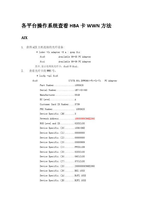
各平台操作系统查看HBA卡WWN方法AIX1.获得AIX主机连接的光纤设备:# lsdev -Cc adapter -S a | grep fcsfcs0 Available 09-08 FC Adapterfcs1 Available 09-09 FC Adapter其中,显示有两块光纤卡:fcs0和fcs1。
2.查看光纤卡的WWN号:# lscfg -vpl fcs0fcs0 U787B.001.DNWG664-P1-C1-T1 FC AdapterPart Number.................10N8620Serial Number...............1B74404468Manufacturer................001BEC Level....................ACustomer Card ID Number (5759)FRU Number.................. 10N8620Device Specific.(ZM) (3)Network Address.............10000000C96E2898ROS Level and ID............02C82138Device Specific.(Z0)........1036406DDevice Specific.(Z1) (00000000)Device Specific.(Z2) (00000000)Device Specific.(Z3) (03000909)Device Specific.(Z4)........FFC01159Device Specific.(Z5)........02C82138Device Specific.(Z6)........06C12138Device Specific.(Z7)........07C12138Device Specific.(Z8)........20000000C96E2898Device Specific.(Z9)........BS2.10X8Device Specific.(ZA)........B1F2.10X8Device Specific.(ZB)........B2F2.10X8Device Specific.(ZC) (00000000)Hardware Location Code......U787B.001.DNWG664-P1-C1-T1其中标红的部分就是光纤卡的WWN号。
NCP4303ADR2G;NCP4303BDR2G;中文规格书,Datasheet资料
Secondary Side Synchronous Rectification Driver for High Efficiency SMPS Topologies
The NCP4303A/B is a full featured controller and driver tailored to control synchronous rectification circuitry in switch mode power supplies. Thanks to its versatility, it can be used in various topologies such as flyback, forward and Half Bridge Resonant LLC.
(NOTE: For DFN the exposed pad must be either unconnected or preferably connected to ground. The GND pin must be always connected to ground.)
ORDERING INFORMATION
Y
= Year
W
= Work Week
G
= Pb−Free Package
(*Note: Microdot may be in either location)
PINOUT INFORMATION
VCC Min_Toff Min_Ton
Trig/Disable
18 27
36 45
DRV GND COMP CS
This pin detects if the current flows through the SR MOSFET and/or its body diode. Basic turn off detection threshold is 0 mV. A resistor in series with this pin can modify the turn off threshold if needed.
CSNP1GCR01-BOW 1Gb 嵌入式存储设备说明书
CSNP1GCR01-BOWVersion:V1.1JAN20, 2021Revision HistoryVersion Date DescriptionV1.0 16/03/2020 Origin DraftV1.1 20/01/2021 Updated operating temperatureContentsREVISION HISTORY (I)1. INTRODUCTION (1)1.1O VERVIEW (1)1.2F EATURES (1)1.3B LOCK D IAGRAM (1)2. PRODUCT SPECIFICATIONS (2)2.1P IN A SSIGNMENTS (T OP V IEW) (2)2.2P ACKAGE D IMENSIONS (2)3. PERFORMANCE (4)4. DC CHARACTERISTICS (5)5. AC CHARACTERISTICS (6)5.1B US T IMING (D EFAULT M ODE) (6)5.2B US T IMING (H IGH-SPEED M ODE) (6)6. REFERENCE DESIGN (8)1. Introduction1.1 OverviewCSNP1GCR01-BOW is an 1Gb density of embedded storage based on NAND Flash and SD controller. This product has many advantages comparing to raw NAND, it has embedded bad block management, and stronger embedded ECC.CSNP1GCR01-BOW is LGA-8 package. The size is 8mm x 6mm x0.75mm.1.2 Featuresl Interface: Standard SD Specification Version 2.0 with 1-I/O and 4-I/O.l Power supply: Vcc = 2.7V - 3.6Vl Default mode: Variable clock rate 0 - 25 MHz, up to 12.5 MB/sec interface speed (using 4 parallel data lines)l High-Speed mode: Variable clock rate 0 - 50 MHz, up to 25 MB/sec interface speed (using 4 parallel data lines)l Operating Temperature: -30°C to +85°Cl Storage Temperature: -40°C to +85°Cl Standby Current:< 200uA1.3 Block Diagram2. Product Specifications2.1 Pin Assignments (Top View)PIN# SD MODE SPI MODE NAME TYPE1DESCRIPTION NAME TYPE DESCRIPTION1 SDD2 I/O/PP Data Line [Bit2] RSV Reserved2 CD/SDD32I/O/PP3SDNAND Detect/CS I3Chip Select (Neg True)Data Line [Bit3]3 SCLK I Clock SCLK I Clock4 VSS S Supply V oltage Ground VSS S Supply V oltage Ground5 CMD PP Command/Response DI I Data In6 SDD0 I/O/PP Data Line [Bit0] DO O/PP Data Out7 SDD1 I/O/PP Data Line [Bit1] RSV Reserved8 VCC S Supply V oltage VCC S Supply V oltage1) S: power supply; I: input; O: output using push-pull drivers; PP: I/O using push-pull drivers;2) The extended SDD lines (SDD1-SDD3) are input on power up. They start to operate as SDD lines afterSET_BUS_WIDTH command. The Host shall keep its own SDD1-SDD3 lines in input mode, as well,while they are not used. It is defined so, in order to keep compatibility to SDNAND.2.2 Package DimensionsTOP VIEWSIDE VIEWCommon DimensionsSymbol Min Nom Max NoteA 0.65 0.75 0.85B 1.17 1.27 1.37C 6.90 7 7.10D 7.90 8 8.10E 5.90 6 6.10F 10.90 11 11.1H 0.75 0.85 0.95SDNAND Package Dimensions (unit: mm)3. PerformanceParameter RangeWork Model -30°~ 85℃TemperatureStorage Model - 40°~ 85℃Work Model 8% to 95%, Non-condensing HumidityStorage Model 8% to 95%, Non-condensing4. DC CharacteristicsSymbol PARAMETER CONDITIONS MIN TYP MAX UNITS V IL Input low voltage VSS-0.3 0.25VCC V V IH Input high voltage 0.625VCC VCC+0.3 VV OL Output low voltage IOL=100μA@VCC_min0.125VCC VV OH Output high voltage IOH=100μA@VCC_min0.75VCC VI IN Input leakage current VIN=VCC or 0 -10 +/-1 10 μAI OUT Tri-state output leakagecurrent-10 +/-1 10 μAI STBY Standby current 3.3V@clockstop150 200 μAI OP Operation current 3.3v@50MHz(Write)15 25 mA 3.3v@50MHz(Read)15 25 mA5. AC Characteristics5.1 Bus Timing (Default Mode)SYMBOL PARAMETER MIN MAX UNIT NOTEF SD SD clock frequency 0 25 MHzT WL Clock low time 10 nsT WH Clock high time 10 nsT TLH Clock rise time 10 nsT THL Clock fall time 10 nsT ISU Input setup time 5 nsT IH Input hold time 5 nsT ODLY Output delay time 0 14 ns5.2 Bus Timing (High-speed Mode)SYMBOL PARAMETER MIN MAX UNIT NOTEF SD SD clock frequency 0 25 MHzT WL Clock low time 10 nsT WH Clock high time 10 nsT TLH Clock rise time 10 nsT THL Clock fall time 10 nsT ISU Input setup time 5 nsT IH Input hold time 5 nsT ODLY Output delay time 0 14 nsT OH Output hold time 2.5 nsCSNP1GCR01-BOW8 6. Reference DesignNote :R DAT and R CMD (10K~100 kΩ) are pull-up resistors protecting the CMD and the DAT lines against bus floating when SDNAND is in a high-impedance mode.The host shall pull-up all DAT0-3 lines by R DAT , even if the host uses the SDNAND as 1-bit mode only in SD mode. It is recommended to have 2.2uF capacitance on VCC.R CLKreference 0~120 Ω.。
移动联通网络知识考试:诺西BTS设备基维护知识(题库版)
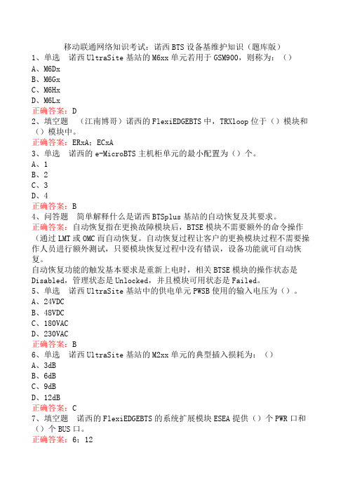
移动联通网络知识考试:诺西BTS设备基维护知识(题库版)1、单选诺西UltraSite基站的M6xx单元若用于GSM900,则称为:()A、M6DxB、M6GxC、M6HxD、M6Lx正确答案:D2、填空题(江南博哥)诺西的FlexiEDGEBTS中,TRXloop位于()模块和()模块中。
正确答案:ERxA;ECxA3、单选诺西的e-MicroBTS主机柜单元的最小配置为()个。
A、1B、2C、3D、4正确答案:B4、问答题简单解释什么是诺西BTSplus基站的自动恢复及其要求。
正确答案:自动恢复指在更换故障模块后,BTSE模块不需要额外的命令操作(通过LMT或OMC而自动恢复。
自动恢复过程让客户的更换模块过程不需要操作人员进行额外测试,只要模块恢复过程中没有错误,设备功能就可自动恢复。
自动恢复功能的触发基本要求是重新上电时,相关BTSE模块的操作状态是Disabled,管理状态是Unlocked,并且模块可用状态是Failed。
5、单选诺西UltraSite基站中的供电单元PWSB使用的输入电压为()。
A、24VDCB、48VDCC、180VACD、230VAC正确答案:B6、单选诺西UltraSite基站的M2xx单元的典型插入损耗为:()A、3dBB、6dBC、9dBD、12dB正确答案:C7、填空题诺西的FlexiEDGEBTS的系统扩展模块ESEA提供()个PWR口和()个BUS口。
正确答案:6;128、单选如果诺西UltraSite基站的TSxx单元前面板上的LED显示为黄色长亮,则表示TSxx:()A、未提供服务B、服务中,发射机关C、服务中,发射机开D、故障正确答案:B9、问答题列举诺西基站7606告警的主要触发原因。
正确答案:(1)天馈系统问题引起由于天馈驻波比过高或载波本身问题造成(2)硬件及数据配置问题由于硬件连接问题、载波本身故障或BSC数据问题造成10、填空题诺西BS24x/BS4x基站载频单元功率控制分为()级静态功率控制(每级2dB)和另外()级动态功率控制(每级2dB)。
机房和施工组织模板

江西新昌电厂“上大压小〞新建工程厂级管理信息系统〔MIS〕网络及硬件平台系统集成投标文件投标编号:03-ct-03-2007-156〔第三卷附件1-技术标准书〕投标人:安徽科大恒星电子商务技术二00九年四月目录第一章概述 (1)工程建设需求 (1)设计原那么 (2)实用性与先进性相结合 (2)可扩展性和开放性 (2)可靠性和平安性 (3)可管理性 (3)设计、施工标准 (3)工程建设目标 (6)第二章效劳器系统平台设计 (7)建设需求 (7)数据库效劳器设计 (7)IBM power550方案 (7)效劳器选型 (7)2.2.1.2 IBM Power 550配置 (12)HP 小型机方案 (13)效劳器选型 (13)2.2.2.2 HP Integrity rx6600 配置 (17)系统运行模式设计 (17)并行处理模式 (18)任务分担模式 (18)主机备用模式 (18)其它效劳器设计 (18)效劳器的部署 (18)物理效劳器与逻辑效劳器之间的关系 (19)效劳器选型设计 (20)2.3.3.1 IBM X3850 M2方案 (20)2.3.3.2 HP ProLiant DL580 G5 效劳器方案 (23)效劳器配置 (26)2.3.4.1 IBM X3850 M2配置 (26)2.3.4.2 HP ProLiant DL580 G5配置 (27)SAN存储系统设计 (27)2.4.1 IBM TotalStorage DS4800方案 (28)2.4.1.1 IBM TotalStorage DS4800介绍 (28)2.4.1.2 TotalStorage DS4800配置 (31)2.4.2 HP StorageWorks EVA8100方案 (32)2.4.2.1 HP StorageWorks EV A8100介绍 (32)2.4.2.2 HP StorageWorks EV A8100配置 (35)光纤交换机选型 (36)2.4.3.1 IBM System Storage SAN2005-B16 特性 (36)2.4.3.2 IBM System Storage SAN2005-B16 配置 (38)数据备份系统 (38)数据备份需求 (38)数据备份方案 (39)2.5.2.1 Veritas的优势 (39)2.5.2.2 Veritas配置 (42)磁带库选型配置 (43)虚拟磁带库选型 (44)第三章网络系统平台设计 (49)网络建设需求 (49)网络拓扑结构设计 (49)分层设计 (49)可靠性保证〔冗余设计〕 (49)网络拓扑实现 (50)核心层设计 (51)接入层设计 (51)远程访问层设计 (51)Cisco解决方案 (51)中心交换机选型 (51)3.3.1.1 Cisco® 6500介绍 (52)3.3.1.2 Supervisor Engine 720 (56)3.3.1.3 Cisco Catalyst 6513配置 (58)接入交换机选型 (59)H3C解决方案 (59)中心交换机选型 (59)H3C S7500E介绍 (60)H3C S7510E配置 (63)接入交换机选型 (63)第四章系统平安设计 (65)系统平安需求 (65)系统平安体系结构 (65)物理设备平安 (65)访问平安 (66)应用平安 (66)数据平安 (66)平安策略 (67)传输通道和传输设备平安 (67)应用平台平安 (68)资源访问平安 (68)网络防病毒 (69)多功能防火墙设计 (70)HillstoneSA-5020介绍 (71)HillstoneSA-5020功能规格 (72)内网核心平安防护系统〔主机加固〕设计 (74)S-NUMEN用途 (74)S-NUMEN功能 (75)S-NUMEN配置 (76)内网主机审计及监管系统 (76)系统功能 (77)系统特点 (79)体系架构 (80)配置 (81)防病毒系统设计 (81)网络防病毒配置 (84)第五章综合布线系统设计 (85)综合布线系统需求 (85)设计标准与设计目标 (85)设计标准 (85)设计目标 (86)布线系统设计 (86)光缆敷设 (86)SAN光纤走向 (86)布线系统测试 (87)测试标准与内容 (89)提交文档 (94)第六章工程组织与管理 (95)工程管理与目标 (95)工程组织及人力资源分配 (96)施工组织总体部署 (96)人力资源配置 (98)与相关单位合作 (99)与工程单位合作 (99)与厂商合作 (100)工程管理 (100)管理方法 (100)管理措施 (101)工程风险管理 (104)工程进度管理 (104)工程质量控制与保证 (105)工程阶段性评估 (106)第七章工程实施方案 (107)工程实施环节规划 (107)实施环节规划总表 (107)设计联络 (109)设备订货及到货 (110)实施现场情况调研 (110)制定详细实施方案 (111)培训 (111)设备验收 (111)查验设备 (111)查验方法 (112)查验报告 (117)系统安装调试 (117)系统调试方案制定 (117)小型机调试 (118)中心交换机调试 (118)边缘交换机调试 (118)中心路由器调试 (119)网管软件调试 (119)主机调试 (119)备份系统调试 (120)系统初验收 (120)试运行 (120)技术文档的提交 (121)系统终验 (121)技术支持与售后效劳 (121)实施进度方案 (121)里程碑事件及考核标准 (122)第八章验收方案与文档 (123)验收测试内容 (123)现场验收测试 (124)文档验收 (126)系统初验收 (126)系统终验 (127)测试方案 (127)测试方法 (127)测试工程 (127)测试方法 (128)工程文档 (129)工程文档内容 (129)工程文档提交方案 (132)第九章机房建设工程 (134)工程简述 (134)电子计算机机房组成及使用面积确定 (134)可维护性设备布置 (135)设计原那么 (135)计算机机房平安分类 (135)建设标准 (137)设计依据 (138)设计依据 (138)设计指标 (140)机柜及机房隔断、装饰设计 (141)机柜 (141)图腾机柜概述 (141)图腾机柜选型 (141)机房隔断 (141)装饰设计 (142)装修材料选材 (142)材料表 (143)吊顶 (143)地面 (144)墙、柱面 (145)门、窗 (145)供配电系统〔含UPS、照明等〕 (146)电气概述 (146)供配电系统 (147)设计标准要求 (147)9.5.2.2 机房配电冗余供电系统 (149)配电设备 (149)UPS系统 (149)UPS选型选型 (149)艾默生“UL33〞系列UPS性能参数 (150)美国“艾默生〞系列UPS特点 (151)电池配置 (151)照明系统设计 (152)普通照明系统设计 (153)应急照明、疏导灯具系统设计 (153)配电线路安装技术 (153)空调系统 (154)空调系统设计 (154)空调设备选型 (154)防雷接地 (154)防雷系统概述 (154)对雷电引入的分析 (155)机房防雷设计 (156)防雷验收及保障 (156)接地系统概述 (156)接地系统解决措施 (157)机房的地线系统 (157)局部等电位连接 (157)抗静电保护地 (157)静电防护 (158)KVM设备及机房布线 (158)KVM设计需求 (158)KVM设计方案说明 (159)环境监控、消防报警及其他相关效劳 (159)环境监控 (159)门禁系统 (159)视频监控 (159)动力环境监控 (159)消防报警 (160)9.9.3 控制台桌椅 (161)灾害处理 (161)机房区防水防护措施 (161)机房给水排水技术 (161)防虫、防鼠害 (162)电磁屏蔽 (162)第一章概述江西新昌电厂网络及硬件平台系统集成工程建设主要包括了网络系统、无线网络覆盖、效劳器系统、存储系统、数据备份系统、微软AD域设计及网络部署、管理及系统软件、MIS终端、智能机房、综合布线等系统,按现代先进技术设计,该系统集成完成后,新昌电厂具有统一的生产MIS系统运行平台,能为其信息化建设提供良好的根底效劳。
P1606dn网络打印机安装教程
HP LaserJet Professional P1606dn 网络打印机安装教程
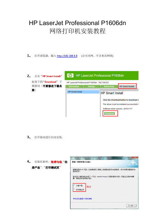
1、打开浏览器,输入http://192.168.8.8(公司内网、不含来宾网络)
2、点击“HP Smart Install”
标签下的“Download”下
载驱动(不要修改下载名
称)
3、打开驱动进行自动安装。
4、安装结束时,取消勾选“注
册产品”、“打印测试页”
5、驱动部分完成安装,弹出“帮助导航”,右上角关闭。
6、取消“双向打印”(非双面打印)
a)点击Windows 图标(),--“设置”然后点击“设备和打印机”。
b)右键点击HP P1606dn,然后点击“属性”。
(Windows7 为“打印机属性”)
c)点击“端口”选项卡。
图 1: 打印机属性中的“端口”选项卡
d)确保没有选中“启用双向支持”复选框。
如果已选中,请点击该复选框,点击“应用”,
或“确定”。
7、安装配置完成,打印机安装完成。
办公自动化设备配置清单

办公自动化设备配置清单一、引言办公自动化设备是现代办公环境中必不可少的工具,能够提高办公效率,减少人力资源的浪费。
本文将详细介绍办公自动化设备的配置清单,包括设备名称、规格型号、数量以及相关说明。
二、设备配置清单1. 电脑设备- 设备名称:台式电脑- 规格型号:HP ProDesk 600 G5- 数量:30台- 说明:配置Intel Core i5处理器、8GB内存、256GB固态硬盘,支持Windows 10操作系统。
2. 打印设备- 设备名称:彩色激光打印机- 规格型号:HP Color LaserJet Pro MFP M281fdw- 数量:5台- 说明:支持彩色打印、扫描、复印和传真功能,打印速度高达22页/分钟,支持双面打印。
3. 多功能一体机- 设备名称:多功能一体机- 规格型号:Canon PIXMA TR8620- 数量:10台- 说明:支持打印、扫描、复印和传真功能,具备无线网络连接和自动双面打印功能。
4. 投影设备- 设备名称:投影仪- 规格型号:Epson VS355- 数量:3台- 说明:支持高清投影,亮度达到3300流明,投影距离范围广,适合于中小型会议室。
5. 电话设备- 设备名称:IP电话- 规格型号:Cisco IP Phone 8841- 数量:20台- 说明:支持高清语音通话、多路线扩展、可编程按键等功能,适合于办公室内部通信。
6. 影音设备- 设备名称:音响系统- 规格型号:Bose SoundTouch 300- 数量:1套- 说明:包括SoundTouch 300声音栏、Acoustimass 300低音炮和Virtually Invisible 300环绕音箱,支持无线连接和蓝牙音频传输。
7. 安全设备- 设备名称:监控摄像头- 规格型号:Hikvision DS-2CD2346G2-I- 数量:8台- 说明:支持高清视频监控、智能分析和远程访问功能,适合于办公室安全监控。
NC服务器相关配置
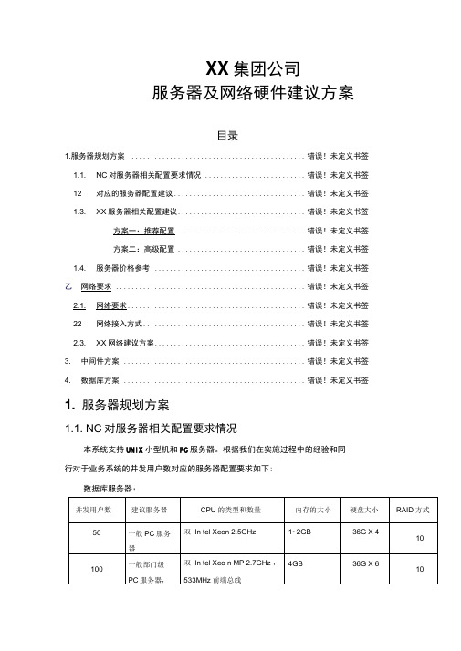
XX集团公司服务器及网络硬件建议方案目录1.服务器规划方案............................................. 错误!未定义书签1.1. NC对服务器相关配置要求情况 .......................... 错误!未定义书签12 对应的服务器配置建议.................................. 错误!未定义书签1.3. XX服务器相关配置建议................................. 错误!未定义书签方案一:推荐配置 ................................ 错误!未定义书签方案二:高级配置 ................................. 错误!未定义书签1.4. 服务器价格参考........................................ 错误!未定义书签乙网络要求................................................. 错误!未定义书签2.1. 网络要求.............................................. 错误!未定义书签22 网络接入方式.......................................... 错误!未定义书签2.3. XX网络建议方案....................................... 错误!未定义书签3. 中间件方案............................................... 错误!未定义书签4. 数据库方案............................................... 错误!未定义书签1. 服务器规划方案1.1. NC对服务器相关配置要求情况本系统支持UNIX小型机和PC服务器。
NCP1396ADR2G,NCP1396ADR2G,NCP1396ADR2G,NCP1396BDR2G,NCP1396BDR2G, 规格书,Datasheet 资料
GND
Fast Fault
DT Vdd
IDT
IBO
20 ms Noise Filter Q S 20 ms Noise Filter Q R PON Reset
BO
+ VBO
+ -
+ Vlatch
+ -
Slow Fault
+ Vref Fault
+ -
Figure 2. Internal Circuit Architecture
NC
Vdd
PON Reset Fault
VCC Fault
ISS SS
FB
G=1
+ -
Mlower > 0 only V = V(FB) - Vfb_min Vdd
RFB
+ Vfb_fault
+ -
+ Vfb_min Vref + Deadtime Adjustment + Vref Fault 20 ns Noise Filter
2
芯天下--/
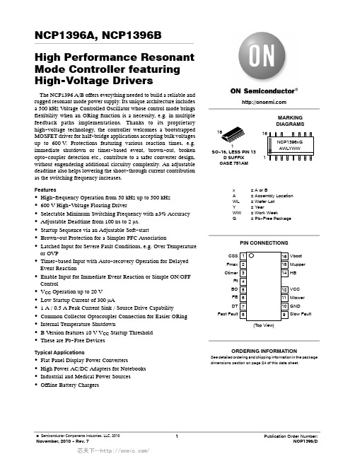
NCP1396A, NCP1396B
Vdd
Temperature Shutdown S D Q Clk R DT Adj. 50% DC FF VCC Management Mupper Q Vref VBOOT
Imin Vfb Vfb_off Vref Rt C I = Imax for Vfb = 5.3 V I = 0 for Vfb < Vfb_min Vdd IDT
Typical Applications
ORDERING INFORMATION
See detailed ordering and shipping information in the package dimensions section on page 24 of this data sheet.
NCP1351BDR2G资料
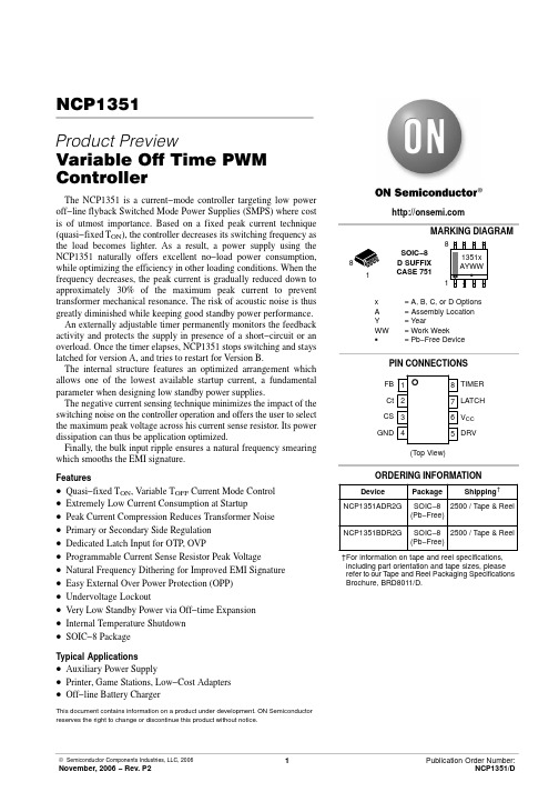
PIN CONNECTIONS
FB 1 Ct 2 CS 3 GND 4
8 TIMER 7 LATCH 6 VCC 5 DRV
(Top View)
ORDERING INFORMATION
Device
Package
Shipping†
NCP1351ADR2G SOIC−8 2500 / Tape & Reel (Pb−Free)
Finally, the bulk input ripple ensures a natural frequency smearing which smooths the EMI signature.
Features
• Quasi−fixed TON, Variable TOFF Current Mode Control • Extremely Low Current Consumption at Startup • Peak Current Compression Reduces Transformer Noise • Primary or Secondary Side Regulation • Dedicated Latch Input for OTP, OVP • Programmable Current Sense Resistor Peak Voltage • Natural Frequency Dithering for Improved EMI Signature • Easy External Over Power Protection (OPP) • Undervoltage Lockout • Very Low Standby Power via Off−time Expansion • Internal Temperature Shutdown • SOIC−8 Package
RG-S6220系列数据中心与云计算交换机产品介绍

面向下一代数据中心与云计算交换机RG-S6220系列产品介绍1 产品图片RG-S6220-48XS4QXSRG-S6220-48XT4QXS图1-1RG-S6220-24XS图1-2RG-S6220-48XS6QXS-H图1-3RG-S6220-48XT6QXS-H图1-4RG-S6220-32QXS-H图1-5RG-S6220-48XS4QXS-L2 产品概述数据中心是通过网络提供服务的“生产工厂”。
近年来,以移动互联网、Web2.0应用、云计算为代表的新型业务迅速发展,数据中心规模开始迅速扩大,并呈现出动态、弹性、灵活、按需调用的特点。
传统网络设备作为数据中心内部最重要的基础设施之一,却由于无法满足弹性、灵活的业务需求而成为当前数据中心发展的瓶颈。
针对当前的问题及趋势,锐捷网络率先推出真正面向下一代数据中心与云计算的交换机产品,将“无阻塞交换、统一交换、虚拟化交换、透明交换、绿色交换”作为下一代数据中心的发展方向,解决传统数据中心网络设备数量多,成本高、流量突增等问题,为构建云计算网络奠定基础。
其中RG-S6220系列交换机是锐捷网络在国内率先推出的面向融合FC/FCoE/IP网络的全万兆云计算特性数据中心交换机。
围绕数据中心与云计算网络虚拟化的趋势,RG-S6220系列交换机采用业界领先的VSU 2.0(Virtual Switch Unit,虚拟交换单元)虚拟化技术将多台物理设备虚拟化为一台逻辑设备,大幅简化网络结构,提高设备可靠性。
RG-S6220系列支持数据中心边缘虚拟交换VEPA、虚拟机发现及安全策略自动迁移等下一代数据中心虚拟化特性。
硬件支持IPv4/IPv6双协议栈多层线速交换和功能特性,并为IPv6网络之间的通信提供丰富的Tunnel技术,可灵活应用于纯IPv4网络、纯IPv6网络、IPv4到IPv6共存的网络,满足当前网络从IPv4向IPv6过渡的需要。
同时,伴随着数据中心融合网络的趋势,RG-S6220系列可为服务器提供FC(Fibre Channel)与FCoE(Fibre Channel over Ethernet)接入和以太网接入服务,同时为传统IP SAN用户提供无损以太网传输,增加IP SAN的可靠性,并且帮助用户轻松整合异构的存储网和数据网,减少数据中心建设成本和复杂性。
ServeRAID 适配器快速参考 - System x 服务器参考信息说明书

ServeRAID Adapter Quick Reference for System x ServersReference InformationWhether you are protecting your storage network, enterprise databases, or application network, the ServeRAID family of SAS/SATA Controllers and Host Bus Adapters delivers benefits to fit your requirements. Combining these controllers with internal disk drives or external storage expansion unit increases storage capabilities.Table 1. Adapter positioningHost Bus Adapters Basic RAID (emphasis on cost)Enterprise RAID (emphasis onperformance)12 Gbps SAS N2215N2225N2226ServeRAID M1215ServeRAID M5225-2GBServeRAID M5210ServeRAID M5210e6 Gbps SAS N2125N2115IBM 6Gb PerformanceOptimized HBAIBM 6Gb SAS HBA ServeRAID M1115ServeRAID H1135ServeRAID H1110ServeRAID M1015ServeRAID M5120ServeRAID M5115ServeRAID M5110ServeRAID M5110eServeRAID M5025ServeRAID M5016ServeRAID M5015ServeRAID M50143 Gbps SAS ServeRAID BR10il v2 3 Gbps SATA ServeRAID C105ServeRAID C100Figure 1. ServeRAID M5225-2GB SAS/SATA ControllerFigure 2. ServeRAID M5210 SAS/SATA Controller (with an optional cache installed)Feature upgrade matrix for M5200 SeriesThe following table shows feature upgrade matrix for ServeRAID M5200 Series SAS/SATA controllers.Table 4. Feature upgrade matrix for ServeRAID M5200 Series SAS/SATA controllersFeature RAIDController Description Part number Type M5210M5210e Zero Cache RAID 5 and SED UpgradesServeRAID M5200 Series Zero Cache/RAID 5 Upgrade47C8708FoD Yes Cache, RAID 5 and SED Upgrades with no backupServeRAID M5200 Series 1GB Cache/RAID 5 Upgrade47C8656HW Yes Cache, RAID 5 and SED Upgrades with flash backupServeRAID M5200 Series 1GB Flash/RAID 5 Upgrade47C8660HW Yes ServeRAID M5200 Series 2GB Flash/RAID 5 Upgrade47C8664HW Yes ServeRAID M5200 Series 4GB Flash/RAID 5 Upgrade47C8668HW Yes Advanced Upgrades*ServeRAID M5200 Series RAID 6 Upgrade47C8706FoD Yes ServeRAID M5200 Series SSD Performance Accelerator47C8710FoD Yes ServeRAID M5200 Series SSD Caching Enabler47C8712FoD Yes* Advanced Upgrade requires cache upgradeFigure 3. ServeRAID M1215 SAS/SATA ControllerFigure 4. ServeRAID M5120 SAS/SATA Controller (with flash module)Figure 5. ServeRAID M5110 SAS/SATA Controller (with flash module)Figure 6. ServeRAID M1115 SAS/SATA ControllerFigure 7. ServeRAID H1110 SAS/SATA ControllerFigure 8. ServeRAID M5025 SAS/SATA ControllerFigure 9. ServeRAID M5016 SAS/SATA Controller (with flash module)Figure 10. ServeRAID M5015 SAS/SATA Controller with the battery backup unit attachedFigure 11. ServeRAID M5000 Series Advanced Feature Key attached to the ServeRAID M5015 ControllerFigure 12. ServeRAID M5014 SAS/SATA ControllerFigure 13. ServeRAID M1015 SAS/SATA ControllerFigure 15. ServeRAID-BR10il SAS/SATA Controller v2 (BR10il v2)ServeRAID C100 and C105The ServeRAID C100 and ServeRAID C105 are integrated SATA controllers with software RAID capabilities. They are a cost-effective way to provide reliability, performance, and fault-tolerant disk subsystem management to help safeguard your valuable data and enhance availability.The following figure shows a screenshot from the configuration utility for ServeRAID C100/C105 that displays information about the controller.Figure 16. ServeRAID C100/C105 configuration utility: Controller informationThe ServeRAID C100 and C105 are integrated SATA controllers that come standard with supported servers and cannot be ordered separately. The following table provides the ordering part numbers and feature codes for the additional options.Table 17. Ordering part numbers and feature codesDescription Part number Feature code ServeRAID C100Onboard Onboard ServeRAID C105Onboard Onboard ServeRAID C100 Series RAID 5 Upgrade-FoD*81Y4406A17U8-Pack ServeRAID C105 Controller Enabler**90Y4349A2V7* An FoD upgrade for ServeRAID C100 that enables support for RAID 5.** An FoD upgrade for ServeRAID C105 that enables support for up to eight SATA HDDs.ServeRAID C100 and C105 specificationsThe following table lists specifications for the ServeRAID C100 and C105 controllers.Figure 17. N2225 (left) and N2226 (right) SAS/SATA HBAsFigure 18. N2215 SAS/SATA HBAFigure 19. N2125 SAS/SATA HBAFigure 20. N2115 SAS/SATA HBAFigure 21. 6Gb SAS Host Bus Adapter with the PCIe slot bracket removedFigure 22. 6Gb Performance Optimized HBASupported serversThe following table lists supported System x servers.Table 28. Supported System x servers (Part 1)Serverx3100 M4Y N Y Y Y Y N N N Y Y x3100 M5N N N N N N N N Y Y N x3200 M2N N N N N N N N N Y N x3200 M3Y N Y Y Y Y N N N Y N x3250 M2N N N N N N N N N Y N x3250 M3Y N Y Y Y Y N N N Y N x3250 M4Y N Y Y Y Y N N N Y Y x3250 M5N N N N N N N Y Y N N x3300 M4N N N N N N N N N Y Y x3400 M2Y N Y Y Y Y N N N Y N x3400 M3Y N Y Y Y Y N N N Y N x3500 M2Y N Y Y Y N N N N Y N x3500 M3Y N Y Y Y N N N Y Y N x3500 M4N N N N N N Y*Y*Y Y Y x3530 M4N N N N N N N Y*N Y Y x3550 M2Y N Y Y Y N N N N Y Y x3550 M3Y Y Y Y Y Y N N N Y Y x3550 M4N N N N N N N Y*Y Y Y x3550 M5N N N N N N Y Y N N N x3620 M3N N Y Y Y Y N N N Y N x3630 M3N N Y Y Y N N N N Y N x3630 M4N N N N N N Y*Y*Y Y Y x3650 M2Y N Y Y Y N N N N Y Y x3650 M3Y Y Y Y Y Y N N N Y Y x3650 M4N N N N N N Y*Y*Y Y Y x3650 M4 BD N N N N N N Y Y Y N N x3650 M4 HD N N N N N N Y Y N N N x3650 M5N N N N N N Y Y N N N x3690 X5Y Y**Y Y Y N N N N Y Y x3750 M4 (8722)N N N N N N N N Y Y Y x3750 M4 (8752)N N N N N N N N Y N N x3755 M3N N Y Y Y N N N N Y N x3850 M2/x3950 M2N N N N N N N N N Y Y x3850 X5/x3950 X5Y Y**Y Y Y N N N Y Y Y x3850 X6/x3950 X6N N N N N N N Y Y N N* Supported with Intel Xeon v2 processors.** Supported with Intel Xeon E7 family-based eX5 servers, requires optional M5016 Battery Tray (88Y5874).Table 28. Supported System x servers (Part 2)Server x3100 M4N N N N N N N N Y N Y N N x3100 M5N N N N Y Y N Y Y N Y N Y x3200 M2N N N N N N N N N N N N N x3200 M3N N N N N N N N Y N N N N x3250 M2N N N N N N N N N N N N N x3250 M3N N N N N N N N Y N N N N x3250 M4N N N N N N N N Y N Y N N x3250 M5N N N N Y Y N Y Y N Y N Y x3300 M4N N N N Y Y N Y Y Y N N N x3400 M2N N N N N N N N N N N N N x3400 M3N N N N N N N N Y N N N N x3500 M2N N N N N N N N N N N N N x3500 M3N N N N N N N N Y N N N N x3500 M4N Y N Y Y Y N Y N N N Y Y x3530 M4N N N N Y Y N Y Y Y N N N x3550 M2N N N N N N N N N N N N N x3550 M3N N N N N N N N Y N N N N x3550 M4N Y N Y Y Y N Y N N N Y Y x3550 M5Y Y N Y N N N N N N N Y N x3620 M3N N N N N N N N Y N N N N x3630 M3N N N N N N N N N N N N N x3630 M4N N N N Y Y N Y Y Y N N Y x3650 M2N N N N N N N N N N N N N x3650 M3N N N N N N N N Y N N N N x3650 M4N Y N N Y Y Y N N N N Y Y x3650 M4 BD N Y N Y Y Y N Y Y N N Y Y x3650 M4 HD N Y Y N N N N N Y N N Y N x3650 M5Y Y N Y N N N N N N N Y N x3690 X5N N N N N N N N N N N N Y x3750 M4 (8722)N N N N Y Y Y Y Y N N N Y x3750 M4 (8752)N Y Y Y Y N N N N N N Y N x3755 M3N N N N N N N N N N N N N x3850 M2/x3950 M2N N N N N N N N N N N N N x3850 X5/x3950 X5N N N N N N N N N N N N Y x3850 X6/x3950 X6NYNNYNNNNNNYNThe following table lists supported iDataPlex and NeXtScale servers.Table 29. Supported iDataPlex and NeXtScale servers (Part 1)Server dx320N N N N N N N N N N N N dx340N N N N N N N N N N N N dx360N N N N N N N N N N N N dx360 M2N N N N N N N N N N N N dx360 M3N N Y N Y N N N N N Y N dx360 M4N N N N N N Y N N N Y Y nx360 M4N N N N N N N Y Y Y N N nx360 M5NNNNNNNNNNNNTable 29. Supported iDataPlex and NeXtScale servers (Part 2)Server dx320N N N N N N N N N N N N N dx340N N N N N N N N N N N N N dx360N N N N N N N N N N N N N dx360 M2N N N N N N N N N N N N N dx360 M3N N N N N N N N Y N N N N dx360 M4N Y N N Y N N Y Y N N N N nx360 M4N N N N Y Y N Y Y N Y N Y nx360 M5NYNYNNNNNNNYNThe following table lists supported BladeCenter servers.Table 30. Supported BladeCenter serversServer HS12 (8028)N N N HS22 (7870)N N N HS22V (7871)N N N HS23 (7875)N N N HS23E (8038)N Y Y HX5 (7872)N N N HX5 (7873)NNNThe following table lists supported Flex System servers.Table 31. Supported Flex System serversServerx220Y Y Y N x222N N N Y x240Y N N N x240 M5N N N N x440Y N N N x280/x480/x880 X6N N N NFeature comparisonThe following tables compare features of the storage controllers.Table 32. Feature comparison: Controllers for System x, iDataPlex, and NeXtScale servers (Part 1)FeaturePort interface SAS SAS SAS SAS SAS SAS SAS SAS SAS SAS SAS Port speed, Gbps6666631212666 Number of ports888884168888 PCIe spec 2.0 2.0 2.0 2.0 2.0 1.0 3.0 3.0 3.0 2.0 2.0 PCIe lanes x8x8x8x8x8x4x8x8x8x8x8 Int. connectors022******** Ext. connectors20000042210 SAS controller LSISAS2108LSISAS2208LSISAS2108LSISAS2108LSISAS2008LSISAS1064LSISAS3008LSISAS3008LSISAS2308LSISAS2008LSISAS2008 Cache (MB)#5121024512256None None None None None None None Battery backup Y N Y Opt N N N N N N N Flash backup N Y N N N N N N N N N Data encryption Opt Y Opt Opt Opt N N N N N N Max stripe size (KB) (F=fixed)10241024102410246464-F N/A N/A N/A N/A N/A Mixing SAS & SATA‡Y Y Y Y Y Y N/A N/A N/A N/A N/A SSD support Y Y Y Y Y Y Y Y N N Y Tape support N N N N N N N N N Y N Max volumes64646464162N/A N/A N/A N/A N/A Max volume size64TB64TB64TB64TB64TB Y N/A N/A N/A N/A N/A UEFI support Y Y Y Y Y Y Y Y Y Y Y Patrol read (data scrubbing)Y Y Y Y Y Y N/A N/A N/A N/A N/A Consistency check Y Y Y Y Y N/A N/A N/A N/A N/A Online RAID Level Migration†Y Y Y Y Y N/A N/A N/A N/A N/A Online Capacity Expansion Y Y Y Y Y N/A N/A N/A N/A N/A AutoSync (auto-rebuild)Y Y Y Y Y Y N/A N/A N/A N/A N/A Copyback§Y Y Y Y N N N/A N/A N/A N/A N/A FastPath Opt N Opt Opt N N N/A N/A N/A N/A N/A CacheCade Opt N Opt Opt N N N/A N/A N/A N/A N/A RAID-0Y Y Y Y Y Y N/A N/A N/A N/A N/A RAID-1Y Y Y Y Y Y N/A N/A N/A N/A N/A RAID-1E N N N N N Y N/A N/A N/A N/A N/A RAID-5Y Y Y Y Opt N N/A N/A N/A N/A N/A RAID-6Opt Y Opt Opt N N N/A N/A N/A N/A N/A RAID-10Y Y Y Y Y N N/A N/A N/A N/A N/A RAID-50Y Y Y Y Opt N N/A N/A N/A N/A N/A RAID-60Opt Y Opt Opt N N N/A N/A N/A N/A N/A# Opt=optional‡ Requires that the server also supports the mixing of SAS & SATA drives.† Online RAID Level Migration (RLM) is also known as Logical Drive Migration (LDM).§ Copyback is also known as Revertible Hot Spare.Table 32. Feature comparison: Controllers for System x, iDataPlex, and NeXtScale servers (Part 2)FeaturePort interface SAS SAS SAS SAS SAS SAS SAS SATA SATA SAS SAS Port speed, Gbps121212666633126 Number of ports88888848Up to688 PCIe spec 3.0 3.0 3.0 3.0 3.0 2.0 2.0N/A N/A 3.0 3.0 PCIe lanes x8x8x8x8x8x8x4N/A N/A x8x8 Int. connectors02202222Up to622 Ext. connectors20020000000 SAS controller LSISAS3108LSISAS3108LSISAS3008LSISAS2208LSISAS2208LSISAS2008LSISAS2004None None LSISAS3008LSISAS2308 Cache (MB)# 2 GB Opt N Opt Opt N N N N N N Battery backup N N N Opt Opt N N N N N N Flash backup Yes Opt N Opt Opt N N N N N N Data encryption Yes Opt Opt Opt Opt Opt N N N N N Max stripe size (KB) (F=fixed)1024102464-F1024102464-F64-F64-F64-F N/A N/A Mixing SAS & SATA‡Y Y Y Y Y Y Y N N Y Y SSD support Y Y Y Y Y Y Y N N Y Y Tape support N N N N N N N N Y N N Max volumes646432646416288N/A N/A Max volume size64TB64TB>2TB64TB64TB64TB16TB>2TB>2TB N/A N/A UEFI support Y Y Y Y Y Y Y Y Y Y Y Patrol read (data scrubbing)Y Y Y Y Y Y N N N N/A N/A Consistency check Y Y Y Y Y Y Y Y Y N/A N/A Online RAID Level Migration†Y Y Y Y Y Y N N N N/A N/A Online Capacity Expansion Y Y Y Y Y Y Y N N N/A N/A AutoSync (auto-rebuild)Y Y Y Y Y Y Y Y Y N/A N/A Copyback§Y Y Y Y Y Y N N N N/A N/A FastPath Opt Opt N Opt Opt N N N N N/A N/A CacheCade Opt Opt N Opt Opt N N N N N/A N/A RAID-0Y Y Y Y Y Y Y Y Y N/A N/A RAID-1Y Y Y Y Y Y Y Y Y N/A N/A RAID-1E N N N N N N Y N N N/A N/A RAID-5Y Opt Opt Opt Opt Opt N N N N/A N/ARAID-6Opt OptNOptOpt NN NN N/AN/ARAID-10Y Y Y Y Y Y Y Y Y N/A N/A RAID-50Y Opt Opt Opt Opt Opt N N N N/A N/A RAID-60Opt Opt N Opt Opt N N N N N/A N/A Feature# Opt=optional‡ Requires that the server also supports the mixing of SAS & SATA drives.† Online RAID Level Migration (RLM) is also known as Logical Drive Migration (LDM).§ Copyback is also known as Revertible Hot Spare.Table 33. Feature comparison: ServeRAID controllers for BladeCenter and Flex System servers。
Bulletin 1606 电源供应器说明书
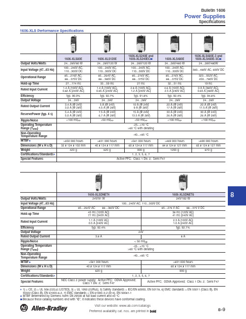
8Specifications91) = CE, 2) = UL 508 (cULus LISTED), 3) = UL 1950 (cURus), 5) Safety standards = IEC/EN 60950, EN 50178, 6) EMC standards = EN 55011 (Class B), EN55022 (Class B), EN 61000-6-2, 7) EMC standards = EN 61000-3-2 (A14), EN 50081-1♣MTBF determined by Siemens norm SN 29500 at full load current and 40 °C1606-XLS80E1606-XLS120E 1606-XLS240E and1606-XLS240EC1606-XLS480E1606-XLS480E-3 and1606-XLS480E-3C1606-XLSDNET41606-XLSDNET8 24V/9181606-XLESpecifications, Continued91) = CE, 2) = UL 508 (cULus LISTED), 3) = UL 1950 (cURus), 4) = CSA C22.2, No. 107-1, 5) Safety standards = IEC/EN 60950, EN 50178, 6) EMC standards = EN 55011 (Class B), EN 55022 (Class B), EN 61000-6-2, 7) EMC standards = EN 61000-3-2 (A14), EN 50081-1§MTBF determined by Siemens norm SN 29500 at full load current and 40 °Ca Because this catalog number ends with C, it indicates the device has conformal coating.Available in regional voltages: add N to the end of the cat. no. for 90...132V, or add E to the end of the cat. no. for 180...264V.8Specifications, Continued1606-XLP Compact Specifications91) = CE, 2) = UL 508 (cULus LISTED), 3) = UL 1950 (cURus), 4) = CSA C22.2, No. 60950, 5) Safety standards = IEC/EN 60950, EN 50178, 6) EMC standards =EN 55011 (Class B), EN 55022 (Class B), EN 61000-6-2, 7) EMC standards = EN 61000-3-2 (A14), EN 50081-11606-XLP25A 1606-XLP30B1606-XLP30E 1606-XLP36C 1606-XLP50B8Specifications, Continued91) = CE, 2) = UL 508 (cULus LISTED), 3) = UL 1950 (cURus), 4) = CSA C22.2, No. 60950, 5) Safety standards = IEC/EN 60950, EN 50178, 6) EMC standards =EN 55011 (Class B), EN 55022 (Class B), EN 61000-6-2, 7) EMC standards = EN 61000-3-2 (A14), EN 50081-11606-XLP50E1606-XLP50EZ1606-XLP50F1606-XLP72E1606-XLP90B1606-XLP90E-2 1606-XLP95E1606-XLP100E1606-XLP100F1606-XLP100E-28Specifications, Continued1606-XL Single Phase Specifications91) = CE, 2) = UL 508 (cULus LISTED), 3) = UL 1950 (cURus), 4) = CSA C22.2, No. 60950, 5) Safety standards = IEC/EN 60950, EN 50178, 6) EMC standards =EN 55011 (Class B), EN 55022 (Class B), EN 61000-6-2, 7) EMC standards = EN 61000-3-2 (A14), EN 50081-1‡Low inrush current♣MTBF determined by Siemens norm SN 29500 at full load current and 40 °C1606-XL60D1606-XL180B 1606-XL480EP1606-XL480EPT1606-XL480GP 1606-XL480F Output Volts/Watts 24V/60 W12...15V/180 W 24...28V/480 W36...43V/480 W48...56V/480 WInput Voltage (47...63Hz)100...120/200...240V ACmanual select;160...375V DC 100...120/220...240V AC240...375V DC 100...120/200...240V AC Operational Range 85...132/176...264V AC 85...132/176...264V AC 85...132/184...264V ACHold-up Time >20 ms (196V AC)>81 ms (230V AC)>84 ms (120V AC)>45 ms (100V AC)30 ms (120/230V AC)>27 ms (230V AC)30 ms (230V AC)Rated Input Current <1.3 A (115V)/<0.7A(230V)<5A (115V)/<2.3 A (230V)10 A (115V)/5 A (230V)Efficiency typ. 87.5%typ. >87%typ. 90.5%typ. 92%typ. 93%Output Voltage 24V 12...15V Preset at 12V 24 (28V)Front panel potentiometer36...43V Front panel potentiometer 48...56V Front panel potentiometer Rated Output Current 2.5 A 15 A (@ 12V),12 A (@ 15V)20 A (@ 24V),18 A (@ 28V)13.3 A (@ 36V),11.2 A (@ 43V)10 A (@ 48V),8.6 A (@ 56V)Power Boost ⎯18 A 25 A (22 A)16.6 A (14 A)12.5 A (10.7 A)Ripple/Noise<25 mV pp<50 mV pp< 20 mV pp (single operation)<40 mV pp (parallel operation)<30 mV pp (singleoperation)<80 mV pp (paralleloperation)<40 mV pp (singleoperation)<80 mV pp (paralleloperation)Operating Temperature Range (T amb )-10...+70 °C >60 °C with derating0...70 °C>60 °C with derating 0...+70 °C>60 °C with deratingNon-OperatingTemperature Range -40...+85 °C 0...70 °C>60 °C with derating -40...+85 °C MTBF ♣740 000 hours <425 000 hours 519 000 hours Dimensions (W x H x D)49 x 124 x 102 mm120 x 124 x 102 mm220 x 124 x 102 mm Weight460 g 980 g 2500 g 1800 g Certifications/Standards 91, 2, 3, 4, 5, 6, 71, 2, 3, 4, 5, 61, 2, 3, 4, 5, 6, 71, 2, 3, 4, 5, 6Special Features NEC Class 2 powersupply;Semi F47⎯PFC choke;Overload behaviorselectable;(hiccup/continuouscurrent); ‡PFC choke; ‡Selectable single/parallel operation (inclined characteristic);PFC choke; ‡‡8Specifications, Continued91) = CE, 2) = UL 508 (cULus LISTED), 3) = UL 1950 (cURus), 4) = CSA C22.2, No. 60950, 5) Safety standards = IEC/EN 60950, EN 50178, 6) EMCstandards = EN 55011 (Class B), EN 55022 (Class B), EN 61000-6-2, 7) EMC standards = EN 61000-3-2 (A14), EN 50081-1‡Low inrush current♣MTBF determined by Siemens norm SN 29500 at full load current and 40 °Ca Because this catalog number ends with "C", it indicates the device has conformal coating."Shut Down" InputFunction:Turning the unit on or off using logic signal (remote monitoring).Unit switches off when Input is connected to "Signal GND" terminal (DU ≤1V) or the input has a voltage of +20...28V with respect to the "Signal GND" terminal, (max. 20 mA)."DC Ok" OutputFunction:Indicating whether the unit is operating properly. Output can directly energize a relay or a control light. Signaling:Output signal is at a "high" level (24V, current source) in normal operation (no overload, overheating, short circuit). When the output signal switches to "low" level (no power at output), Vout remains for 5 ms (nominal) at nominal load.Connection (signal common): Connection is made with respect to the "Signal GND" terminal (signal output). Important:Do not connect to the power output (terminals + and -).Permissible load:resistance - min.300 Ω, e.g. 24V relay, control lights (LEDsneed no series resistance), Evaluationlogic.For 5V signal:In order to receive a 5Vsignal: switch a 5V Zener diode (0.5 W)and 1 kΩ, resistance in parallel betweenthis output and the "Signal GND" terminal."Thermal Alarm" OutputFunction:Output gives warning shortlybefore and while overtemperature stateoccurs. Output can directly control a relayor a control light.Signaling:Output signal is at a "high"level (24V, current source) in normaloperation (no overtemperature). Atovertemperature, the output switches to"low". Only when the temperature in theunit increases further will the unit reduceits output current (power output).Connection and permissible load:sameas for "DC ok" output."Current Monitor" OutputFunction:Measuring the output current(power output). Output signal isproportional to the output current of theunit.Connection:Made with respect to the"Signal GND" terminal (signal output).Important:Do not connect to the poweroutput (terminals + and -).Signaling:Voltage measuring: Voltage at signaloutput is 1V per 10 A output current(Ri(voltmeter) > 100 k ohm )Current measurement: Current at signaloutput is 1 mA per 10 A output current(Ri(ammeter) < 100 W)"Current Balance" In-/OutputFunction:Using these terminals, paralleloperating units ensure an equal loadsharing (active balancing). Balancing alsoworks reliably with decoupling diodes atthe power output (redundancy).Connection:Connect together "CurrentBalance" outputs of all units involved.Important:Signal common here is the -terminal of the power output, not the"Signal GND". Do not connect the "SignalGND" terminals to each other!"Signal GND" TerminalFunction:Grounding terminal for all signalterminals (not for "Current Balance").Connection instructions:Do not connectthis terminal with terminals + or - of theunit (not even over a load: risk ofoverload). Do not connect this terminalwith terminals of other units (not even withthe "Signal GND" terminal of another unit).Permissible load:Maximum current load:0.3 A. Terminal is fused internally with aself-healing fuse (polyswitch).ShutDownDCokThermalAlarmCurrentMonitorCurrentBalanceSignal-GNDDC OkThermal A larmSignal-GND5V signal1606-XL120E-31606-XL240E-3 and1606-XL240E-3C1606-XL960E-3S♣8Specifications, Continued91) = CE, 2) = UL 508 (cULus LISTED), 3) = UL 1950 (cURus), 5) Safety standards = IEC/EN 60950, EN 50178, 6 EMC standards = EN 55011 (Class B), EN 55022 (Class B), EN 61000-6-2, 7) = EMC standards = EN 61000-3-2 (A14), EN 50081-1‡Low inrush current§MTBF determined by Siemens norm SN 29500 at full load current and 40 °CBuffer Module UPS DC/DC Converter N+1 Redundancy N+1 Redundancy8Specifications, Continued91) = CE, 2) = UL 508 (cULus LISTED), 3) = UL 1950 (cURus), 5) Safety standards = IEC/EN 60950, EN 50178, 6 EMC standards = EN 55011 (Class B), EN 55022 (Class B), EN 61000-6-2, 7) = EMC standards = EN 61000-3-2 (A14), EN 50081-1§MTBF determined by Siemens norm SN 29500 at full load current and 40 °CN+1 Redundancy N+1 Redundancy N+1 Redundancy N+1 Redundancy。
D84-Extreme远程接入接入解决方案
服务器
1. 对于高安全性的企业内网,两端采用Ipsec VPN提供加密隧道。
2. 可以考虑部署两台AC做主备冗余。 3. 在每台AC上启用IPsec VPN Server功能 4. 在家里面部署AP做PPPoE拨号、数据网关
出口、NAT和IPsec VPN client端。 5. 在AP使用路由优先级去控制访问到总部的数
据走VPN隧道,到Internet的流量走本地。
Internet
IPsec Tunnel IPsec Tunnel
型号:NX9610 IPsec数量:1,024 free
10,080 license
IPsec Tunnel
型号:NX5500 IPsec数量:512 free
1,024 license
IPsec Tunnel
Internet
1. 对于高安全性的企业内网,两端采用Ipsec VPN提供加密隧道。
2. 可以考虑部署1台AC。 3. 架设一台IPsec VPN Server 4. 在家里面部署AP做PPPoE拨号、数据网关
出口、NAT和IPsec VPN client端。 5. 在AP使用路由优先级去控制访问到总部的数
CAPWAP Tunnel CAPWAP Tunnel CAPWAP Tunnel
2
©2014 Extreme Networks, Inc. All rights reserved.
型号:NX5500 接入AP数量:256
型号:RFS4000 接入AP数量:36
Ipsec加密的接入
企业内网
AC/IPsec Server
©2014 Extreme Networks, Inc. All rights reserved.
四路双核 强劲动力
四路双核强劲动力
仝培杰
【期刊名称】《中国计算机用户》
【年(卷),期】2005(000)049
【摘要】曙光天阔1840r-E服务器是曙光公司最新推出的基于四路英特尔新Xeon MP双核处理器的4U机架式企业级服务器,支持最多4颗64位Intel Xeon Paxville MP双核处理器,支持超线程技术(HT)、内存扩展技术(EM64T)和按需配电技术(DBS)。
【总页数】1页(P61)
【作者】仝培杰
【作者单位】《中国计算机用户》记者
【正文语种】中文
【中图分类】TP368.5
【相关文献】
1.英特尔发布全新双核安腾2处理器安腾软硬件解决方案应用强劲增长 [J],
2.双核芯动力国产双核安卓平板的战役 [J], 《电脑迷》评测室
3.心强劲,身小巧--普耐尔MOM07双核极速版 [J],
4.廉价双核3600+如何击败强劲单核FX-55? [J],
5.强劲双核掌控高清摩托罗拉“夺世”XT760智能手机 [J],
因版权原因,仅展示原文概要,查看原文内容请购买。
美国康普推出创新SYSTIMAX360解决方案,重新确立企业网线基础设施的性能标准
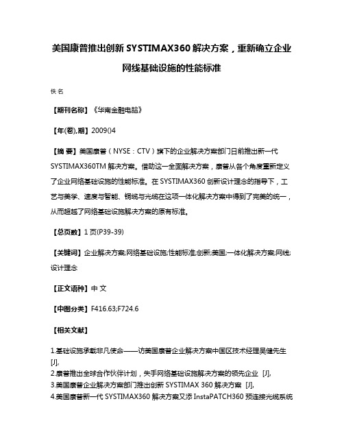
美国康普推出创新SYSTIMAX360解决方案,重新确立企业
网线基础设施的性能标准
佚名
【期刊名称】《华南金融电脑》
【年(卷),期】2009()4
【摘要】美国康普(NYSE:CTV)旗下的企业解决方案部门日前推出新一代SYSTIMAX360TM解决方案。
借助这一全面解决方案,康普从各个角度重新定义了企业网络基础设施的性能标准。
在SYSTIMAX360创新设计理念的指导下,工艺与美学、速度与智能、铜缆与光缆在这项一体化解决方案中得到了完美的统一,从而超越了网络基础设施解决方案的原有标准。
【总页数】1页(P39-39)
【关键词】企业解决方案;网络基础设施;性能标准;创新;美国;一体化解决方案;网线;设计理念
【正文语种】中文
【中图分类】F416.63;F724.6
【相关文献】
1.基础设施承载非凡使命——访美国康普企业解决方案中国区技术经理吴健先生[J],
2.康普推出全球合作伙伴计划,失手网络基础设施解决方案的领先企业 [J],
3.美国康普企业解决方案部门推出创新SYSTIMAX 360解决方案 [J],
4.美国康普新一代SYSTIMAX360解决方案又添InstaPATCH360预连接光缆系统
[J], 王燕
5.美国康普企业解决方案部门推出SYSTIMAX360解决方案 [J],
因版权原因,仅展示原文概要,查看原文内容请购买。
- 1、下载文档前请自行甄别文档内容的完整性,平台不提供额外的编辑、内容补充、找答案等附加服务。
- 2、"仅部分预览"的文档,不可在线预览部分如存在完整性等问题,可反馈申请退款(可完整预览的文档不适用该条件!)。
- 3、如文档侵犯您的权益,请联系客服反馈,我们会尽快为您处理(人工客服工作时间:9:00-18:30)。
Detection (ZCD) demagnetized for critical conduction mode operation. Ground ZCD to shutdown the part.
6
Ground (GND) Connect this pin to the pre−converter ground.
2
Control
The regulation block output is available on this pin. A compensation network is placed between FB
and Control to set the loop bandwidth low enough to yield a high power factor ratio and a low THD.
Measure IEAsink
VDD VEAL Clamp
Static OVP
Static OVP is triggered when clamp is activated.
ESD
VDD 270 mA ESD
VEAH Clamp Add VEAL Offset
PWM − +
nPOK
DRV
LEB ESD
scales and delivers the output voltage to the FB pin to maintain regulation. The feedback information
is also used for the programmable overvoltage and undervoltage protections.
Safety Features
• Programmable Overvoltage Protection • Protection against Open Loop (Undervoltage Protection) • Accurate and Programmable On Time Limitation • Overcurrent Limitation
8
1
SO−8 D SUFFIX CASE 751
MARKING DIAGRAMS
8
1606
DIP−8 P SUFFIX CASE 626
NCP1606x AWL
YYWWG
x
= A or B
A
= Assembly Location
L, WL = Wafer Lot
Y, YY = Year
ROUT1 FB
ROUT2
CCOMP Control
AC IN LBOOST Ct
Ct
CS RSENSE
RZCD
ZCD
Shutdown
nPOK − +
300 mV E/A − ESD +
UVP
ESD
(Enable EA)
Dynamic OVP Isink>Iovp
2.5 V
Enable VCONTROL
VDD VDDGD
Fault
uVDD
VCC UVLO
SQ
RQ
VddGD
uVDD
POK nPOK
DRV GND
*All SR Latches are Reset Dominant *All values shown are typical only. Refer to the “Electrical Characteristics” for complete specifications.
W, WW = Work Week
G or G = Pb−Free Package
PIN CONNECTION
Feedback Control Ct CS
(Top View)
VCC Drive
Ground ZCD/STDWN
ORDERING INFORMATION
See detailed ordering and shipping information in the package dimensions section on page 20 of this data sheet.
3
Ct
The Ct pin sources a 270 mA current to charge an external timing capacitor. The circuit controls the power
switch on time by comparing the Ct voltage to an internal voltage derived from the regulation block.
IFB
±10
mA
Control Voltage
VControl
−0.3 to 10
V
Control Current
IControl
−2 to 10
mA
Ct Voltage
VCt
−0.3 to 6
V
Ct Current
ICt
±10
mA
CS Voltage
VCS
−0.3 to 6
V
CS Current
ICS
© Semiconductor Components Industries, LLC, 2010
1
June, 2010 − Rev. 8
/
Publication Order Number: NCP1606/D
NCP1606
VCC
+ + + +
+ +
+
VOUT
CBULK DBOOST
4
Current Sense This pin limits the pulse by pulse current through the switch MOSFET when connected as show in
(CS)
Figure 1. When the voltage exceeds 1.7 V (A version) or 0.5 V (B version), the drive turns off. The
NCP1606
Cost Effective Power Factor Controller
The NCP1606 is an active power factor controller specifically designed for use as a pre−converter in electronic ballasts, ac−dc adapters and other medium power off line converters (typically up to 300 W). It embeds a Critical Conduction Mode (CRM) scheme that substantially exhibits unity power factor across a wide range of input voltages and power levels. Housed in a DIP8 or SOIC−8 package, the NCP1606 minimizes the number of external components. Its integration of comprehensive safety protection features makes it an excellent driver for rugged PFC stages.
±10
mA
ZCD Voltage
VZCD
−0.3 to 10
V
ZCD Current
IZCD
±10
mA
Power Dissipation and Thermal Characteristics
P suffix, Plastic Package, Case 626
Maximum Power Dissipation @ TA = 70°C Thermal Resistance Junction−to−Air D suffix, Plastic Package, Case 751
+ OCP −
VDD
VCL(NEG) Active Clamp
VCS(limit) +
2.1 V −
Demag SQ
+ − 1.6 V
RQ Off Timer
−
Reset
+
Shutdown
VCL(POS) Clamp
200 mV
uVDD
SQ RQ
SQ RQ SQ RQ
VCC + UVLO −
VDD Reg
General Features
• “Unity” Power Factor • No Need for Input Voltage Sensing • Latching PWM for Cycle by Cycle On Time Control (Voltage Mode) • High Precision Voltage Reference (±1.6% over temperature ranges) • Very Low Startup Current Consumption (≤ 40 mA) • Low Typical Operating Current (2.1 mA) • −500 mA / +800 mA Totem Pole Gate Driver • Undervoltage Lockout with Hysteresis • Pin to Pin Compatible with Industry Standards