VService-SMC安装手册
统信服务器操作系统企业版V20安装手册说明书

统信服务器操作系统企业版V20安装手册统信软件技术有限公司2020年07月目录1.概述 (1)1.1.支持的硬件 (1)1.1.1.支持的体系 (1)1.1.2.多处理器的支持 (2)1.1.3.图形卡的支持 (2)1.1.4.外围设备的支持 (3)1.1.5.存储系统的支持 (3)1.2.需要固件的设备 (3)1.3.避免专有或封闭的硬件 (4)1.4.安装介质 (5)1.4.1.U盘 (5)1.4.2.CD-ROM/DVD-ROM (6)1.4.3.网络 (6)2.安装准备 (7)2.1.备份数据 (7)2.2.硬件环境 (7)2.3.网络设置 (8)2.4.系统分区 (8)2.5.最低配置要求 (10)2.6.获取镜像 (10)2.7.制作安装介质 (10)2.7.1.光盘刻录 (11)2.7.2.U盘制作 (11)2.8.PXE安装配置 (12)2.8.1.概述 (12)2.8.2.网络图 (12)2.8.3.服务器要求 (13)2.8.4.客户机要求 (14)2.8.5.服务器软件安装 (14)2.8.6.NFS安装配置 (14)2.8.7.TFTP安装配置 (15)2.8.8.Dnsmasq安装配置 (17)2.9.相关设置 (19)2.9.1.BIOS设置菜单的使用 (20)2.9.2.选择引导设备 (20)2.9.3.具有UEFI固件的系统 (21)2.9.4.需要留心的硬件问题 (22)3.安装过程 (23)3.1.虚拟机安装 (23)3.1.1.统信操作系统 (23)3.1.2.Windows或其它操作系统 (23)3.2.安装引导 (23)3.2.1.U盘启动 (24)3.2.2.光盘启动(CD/DVD) (24)3.2.3.网络引导启动 (24)3.3.引导界面 (25)3.3.1.Install UOS Server Enterprise20(Graphic) (25)3.3.2.Check ISO md5sum (26)3.4.执行安装 (27)3.4.1.图形方式安装 (27)4.系统配置 (34)4.1.选择时区 (35)4.1.1.地图选择 (35)4.1.2.列表选择 (36)4.1.3.时间设置 (36)4.2.创建用户 (37)4.2.1.创建用户 (37)4.2.2.选择键盘布局 (38)4.3.网络设置 (39)4.4.登录系统 (40)5.使用系统 (42)5.1.激活系统 (43)5.2.更新系统 (44)5.3.关闭系统 (45)1.概述本文档主要讲述的是64-bit设备,统信服务器操作系统企业版V20的安装及相关配置。
服务器安装SOP

服务器安装SOP一、安装SQL SERVER 2000 ENTERPRISE安装SQL2000数据库1.在服务器上安装数据库,需要安装SQL2000企业版,打开安装文件后,出现如下界面:2.点击【安装 SQL Server 2000 组件】,出现如下界面,然后点击【安装数据库服务器】3.点击【下一步】4.选择【本地计算机】,然后点【下一步】5.选择【创建新的SQL Server实例,或安装【客户端工具】】,然后点击【下一步】6.随意输入姓名与公司,然后点击【下一步】7.点击【是】8.选择【服务器和客户端工具】,然后点击【下一步】9.选择【默认】,然后点击【下一步】10.选择【典型】,然后点击【程序文件】后面的【浏览】与【数据文件】后面的【浏览】,将安装的路径全部修改在D盘,然后单击【下一步】11.上面选择【对每个服务使用同一帐户,自动启动SQL Server服务】,下面选择【使用本地系统帐户】,正确选择完成后,单击【下一步】12.身份验证模式需要选择为【混合模式】,然后在下面输入sa的密码,密码为:admin。
密码输入两次完成后,单击【下一步】13.单击【下一步】14.随后系统会进行自动安装并复制文件,请耐心等待15.安装完成后,点击【完成】,会自动退出安装界面安装SQL2000的SP4补丁1.点击安装文件setup.bat,出现安装界面2.单击【下一步】3.点击【是】4.单击【下一步】5.按照默认的选择,直接单击【下一步】6.将【升级Microsoft Search并应用SQL Server 2000 SP4(必需)】打上勾,然后点击【继续】7.直接点击【确定】8.直接单击【下一步】9.安装程序进行文件的复制,请耐心等待10.直接点击【确定】11.单击【完成】注:SP4补丁打完后需要重新启动服务器。
二、安装透明车间安装透明车间数据库1.运行安装包中的CJS_DB_Files_3_0,进行数据库的安装,如下图所示,点击【NEXT】2.一路【NEXT】,直到出现以下的界面,在这里可以选择安装路径。
售后服务微力邮件服务器版安装说明

(售后服务)微力邮件服务器(版)安装说明微力邮件服务器(linux版)安装说明微力邮件服务器(linux版)完整地集所有功能于壹身的通信解决方案不仅包含了普通邮箱管理系统的所有功能,同时也包含有效反病毒、垃圾邮件检测、协同工作组、FTP服务器、Web服务器和安全即时信息服务器等。
互联网协议兼容:SMTP/ESMTP/POP3/IMAP4rev1Jabber/XMPPLDAPHTTP/FTPIPv4/IPv6 SNMPTLS/SSL用于所有适用的协议。
管理员及远程访问:命令行向导设置HTTP管理员界面远程管理员控制台。
微力邮箱管理系统丰富的设置及选项提供多个域及多帐户类型。
除了用户邮件帐号之外,您仍能够创建邮件列表及用于远程服务器邮件恢复的远程帐号。
多域及多用户邮件列表及服务器排列远程帐号执行器目录公告微力邮箱管理系统支持所有的安全功能包括反病毒保护、反垃圾邮件引擎及开放式传播保护等。
安装之后即运行开放式传播保护安全鉴定方案反病毒保护反垃圾邮件保护邮件内容过滤。
存储备份支持:文件系统存储MySQL存储执行过程中ODBC存储硬件需求:x86体系安装大约需要70MB磁盘空间(网络安装大约需要35MB网上空间)软件需求:OpenSSL库Kerberos库Glibcv2.3或更高版本Libz(gzip)库标准DNS库PAM库BashAV 特殊库适用于以下系统的目前可用版本发布前均经过测试及认证:RedHatLinux4ES安装环境:FEDOLA6.0<其它Linux版本安装基本相同>软件版本:merak-8.9.2-6测试版(30天)下载地址:http:///download/linux/merak-latest.html首先把软件安装包下载或者拷贝到本地磁盘中壹已知目录下确定所有的操作于系统管理员的权限下;且且确认系统自带的邮件系统已经卸载防止端口冲突!用管理员身份进入root如果不是请输入:su输入密码:来更改管理员操作;1.解压安装程序包[root@new-host-9icewarp]#tar-xzfmerak-8.9.2-6.tar.gz............/解压缩包/[root@new-host-9icewarp]#ls……………………………./查见目录文件/merak-8.9.2-6merak-8.9.2-6.tar.gz2.安装MERAKforlinux版[root@new-host-9icewarp]#cdmerak-8.9.2-6……………/进入解压文件/[root@new-host-9merak-8.9.2-6]#ls……………………../查见目录文件/ INSTALLinstall.shLICENSEmerak-image-8.9.2-6.tar[root@new-host-9merak-8.9.2-6]#./install.sh…………../执行安装文件事注意程序前的”./”符号系统自动执行安装程序,于屏幕上我们会见到微力邮件系统的安装欢迎屏幕. Installationprefix[/opt/merak]:**Runservicesunderuser[]:root**Runservicesundergroup[]:root//指定运行merak服务的用户和组// ………………………libssl.so library couldn't be found, some parts may not work** libcrypto.so library couldn't be found, some parts may not work**compat-libstdc++-296 package not found! AV engine will not work without it!//之上信息提示LIB文件版本错误,请留意//………………….……………………..///提示信息省略//MerakMailServer**1999-2006IceWarpLtd.**Wizardconfigurationassistant****Loggingisenabledtothefollowingfilesforfuturereference:** Errors: /opt/merak/logs/wizard/merak-wizard-error.log**Actions:/opt/merak/logs/wizard/merak-wizard.log3.添加邮件域和邮件系统管理员壹般情况下安装邮件系统时会自动进入到向导,也可到MERAK的程序文件夹/opt/merak,运行wiard<命令:cd/opt/merk./wizard>**Rootmenu**Youhavethefollowingoptions:****[1]DaemonManagement**[2]AccountsandDomainsManagement**[3]Databasesetup**[4]Advancedoptions**[0]Return**[Q]Exit****Enteryourchoice:2//账号和域管理// AccountsandDomainsManagement**Youhavethefollowingoptions:**[1]Addnewdomain**[2]Deletedomain**[3]Addnewuser**[4]Deleteuser**[0]Return**[Q]Exit****Enteryourchoice:1//添加新域//Createnewdomain:****Domainname:**Domaindescription:icewarpchina//域基本信息,根据自己情况填写//**Administratoremailaddress:admin@ ****OK?[Y/n]y//确认建立新域//**DomaincreatedAddanotherdomain?[Y/n]n//不添加其它域//****AccountsandDomainsManagement Youhavethefollowingoptions:****[1]Addnewdomain**[2]Deletedomain**[3]Addnewuser**[4]Deleteuser****[0]Return**[Q]Exit****Enteryourchoice:3//添加新用户//******Createnewaccount:****Emailaddress:admin@**Password:****Onceagaintoconfirm:**//用户基本信息,根据自己情况填写//**Fullname:administrator**Systemadministrator?[Y/n]y//做为系统管理员用户//****OK?[Y/n]y//确认建立新用户//**Accountcreated**Addanotheruser?[Y/n]n//不添加其它用户//****AccountsandDomainsManagementEnteryourchoice:Q邮件系统中至少需要壹个域和壹个系统管理员帐号,否则系统无法正常运行.4.配置连接库文件Merak利用LIB文件来保证信息传输的安全,不同的LINUX版本LIB文件也不尽相同,如果您使用LINUX是4版本,您将不需要做如下设置,否则您需要libssl.so.4和libcrypto.so.4文件.请留意安装时的提示信息,如出现本例中所显示的LIB错误,请按如下操作.将系统LIB目录</lib>下的libssl.so.6和libcrypto.so.6<不同版本文件名可能有些不同>复制到用户lib目录</usr/lib>且更名为libssl.so.4和libcrypto.so.4.命令如下:或使用通用的文件下载地址:http:///downloads/linux.html[root@new-host-9lib]#cd/lib[root@new-host-9lib]#lslibssl*.*libssl.so.0.9.8blibssl.so.6[root@new-host-9lib]#cplibssl.so.6/usr/lib/libssl.so.4…./拷贝libssl.so.6到usr/lib/目录下且改名为libssl.so.4/[root@new-host-9lib]#lslibcry*.*libcrypt-2.5.solibcrypto.so.0.9.8blibcrypto.so.6libcrypt.so.1[root@new-host-9lib]#cplibcrypto.so.6/usr/lib/libcrypto.so.4…………/拷贝libcrypto.so.6到usr/lib/目录下且且改名为libcrypto.so.4/[root@new-host-9merak]#cd/opt/merak[root@new-host-9merak]#./startd………………………./启动微力邮件系统各服务/ StartingMerakMailServerAVGIntegrationDaemon:[OK] StartingMerakMailServerServiceHelperDaemon:[OK] StartingMerakMailServerServiceControlDaemon:[OK] StartingMerakMailServerSMTPServiceDaemon:[OK] StartingMerakMailServerPOP3/IMAP4ServiceDaemon:[OK] StartingMerakMailServerMessagingServiceDaemon:[OK] StartingMerakMailServerGroupWareServiceDaemon:[OK]安装结束以后我们能够于IE浏览器里输入:http://locahost:32000/mail测试系统是否已经于运行http://localhost:32000/admin进入管理页面注意:LINUX下默认情况登陆账号请不要加后缀,如admin@直接用admin登陆.日常维护:/opt/merak下的stopd用于停止微力邮件系统各服务/opt/merak下的startd启动微力邮件系统各服务/opt/merak下的wizard用于添加/删除邮件系统的域和用户,也能够配置数据库等,详细内容请关注后续教程.。
SMC数字流量开关操作手册说明书

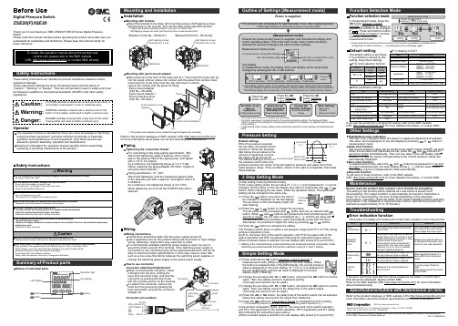
Digital Flow Switch (Display Part) Operation Manual For AirPF2A300/301 SeriesPF2A310/311 SeriesFor Pure Water/Chemical Fluid PF2D300/301 SeriesFor WaterPF2W300/301 SeriesPF2W330/331 SeriesURL SAFETY2Model Indication Method4Name and Functions of Individual Parts 6Installation7Outline with Dimensions8Example of Internal Circuit and Wiring 9Setting 10Initialize11Display Function of Integrated Flow Rate Value 15Instantaneous Flow Rate Setting Mode16Integrated Flow Rate Setting Mode 19Output Selection 20Other Functions 23Specification24CONTENTSThank you for purchasing the SMC PF2*3**Series Digital Flow Switch.Please read this manual carefully before operating digital flow switch and understand digital flow switch, its capabilities and limitations.Please keep this manual handy for future reference.OPERATOR•This operation manual has been written for those who have knowledge of machinery and apparatus that use pneumatic equipment and have full knowledge of assembly, operation and maintenance of such equipment.•Please read this operation manual carefully and understand it before assembling, operating or providing maintenance service to the flow switch.32NOTEFollow the instructions given below when handling your flow switch.Otherwise, the switch may be damaged or may fail, thereby resulting in malfunction.•Do not drop it, bring it into collision with other objects or apply excessive shock (490m/s 2or more).•Wiring correctly.•Do not wiring while power is on.•Although the flow switch complies with the CE Marking, since it does not have the thunder serge protection, please carry out protection to thunder serge by the equipment side.•Although the flow switch complies with the CE Marking, since the equipment and apparatus which are made to generate the serge (Electro-magnetic lifter, High frequency induction furnace, Motor etc.) around the flow switch should perform measure against serge come out.•Do not use with power cable or high-voltage cable in the same wire route.•Do not use in a place in which water, oil, or a chemical splashes.•Do not push the setting buttons by a sharply pointed object.•Turn on the power supply of a flow switch for Air, when flow is zero.Some initial drift occurs during ten minutes after turning the power on.•Start measurement by the flow switch three seconds after turning on the power. (Also in momentary interception of the power supply by reset etc.) Please take a measure by the program of equipment etc.•Maintain the switch status for measurement output before setting when initializing or setting a flow rate of the flow switch.Measure after checking impacts to the equipment.Carry out a setup since a control system is shut down if required.The Digital Flow Switch and this manual contain essentialinformation for the protection of users and others from possible injury and property damage and to ensure correct handling.Please check that you fully understand the definition of the following messages (signs)before going on to read the text, and always follow the instructions.Please read the operation manuals of related apparatus and understand it before operating the flow switch.Do not disassemble, remodel (including change of printed circuit board) or repair.An injury or failure can result.Do not operate beyond specification range.Fire, malfunction or switch damage can result.Please use it after confirming the specification.Do not operate in atmosphere of an inflammable, an explosive and corrosive gas.Fire or an explosion can result.This flow switch is not an explosion-proof type.54NOTE 1:The new Measurement Low prohibits use in Japan of flowswitches with a unit selection function.NOTE 2:Fixed unit for instantaneous flow rate is :L/minfor integrated flow rate is :LSeparate Type Display PartA : AirD : Pure Water/Chemical Fluid W : Water•About sensor partThe type of the sensor part combined with a display part is indicated to be PF *5**with this manual.Refer to the following correspondence table for the sensor part type combined with each display part.BodyOutput (OUT1) Lamp (Green):Lit when OUT1 is ON. Flickers when an overcurrent erroroccurs.Output (OUT2) Lamp (Red):Lit when OUT2 is ON. Flickers when an overcurrent erroroccurs.LED Display:Displays a flow rate, set mode status, selected display unitand error code.Button (UP): Selects a mode and increases a set ON/OFF value.Button (DOWN): Selects a mode and decreases a set ON/OFFvalue.Button (SET): Changes the mode and sets a set value. RESETPressing the and buttons simultaneously will activate the RESET function.Use this function to clear errors when a trouble occurs.Panel Mount Adapter type ZS-22-EPanel Mount Adapter APanel Mount Adapter BBracket are includedMounting•Install the Display Part on the panel, once the Panel Mount Adaptor Bremoves.•Insert Panel Mount Adapter B supplied as an accessory intoSection A of Panel Mount Adapter A.Push Panel Mount Adapter B from behind till the display is fixedonto the panel.The pin of Panel Mount Adapter B engages the notched part ofPanel Adapter A to fix the display.•The switch can be mounted on a panel with a thickness of 1.0 to3.2mm.•See the illustration below for panel cut dimensions.Panel Cut Dimensions Accessories LED DisplayLamp (Red)SETButton (UP)7 698++0.5Panel Thickness: 1 to 3.2mmPanel Cut DimensionsOutput SpecificationBe sure to select a sensor in SMC PF *5**series for accurate measurement of flow rates.The display outputs only switch output.Analog output is output directly by the sensor part. See theoperation manual of the sensor part for the complete information. Connection•Turn the power off before making connection.•Install the cable separately from the route for power cable or high-voltage cable. Otherwise, malfunction may potentially result due to noise.•Use compression terminals for connection to the terminal board.See the full view of dimensions diagram for details of the terminal board.–0NPN Open Collector Output 2OutputsMax. 30V, 80mAInternal Voltage Drop 1V or less–1PNP Open Collector Output 2Outputs Max 80mAInternal Voltage Drop 1.5V or lessPF ∗5 SeriesPF ∗5 SeriesSetting ProceduresKeep pressing the button longer than two seconds. Remove the finger off the button when one of the characters of LED display column of the following table is displayed.1. Flow Rate Range SettingPress the button and select the flow rate range.Press thebutton to set.2. Display Mode SettingSelect whether to display instantaneous flow rate orintegrated flow rate.To change the Display mode, press thedesired flow rate to display. Then press the button.[d_1] and [d_2] respectively indicate the instantaneous flow rate and integrating flow rate.11103. Selecting Display Unit(In case [-M] is not assigned to unit specification in model indication) Refer to page 14.4. Output Method SettingThree output methods are available, namely, instantaneous switch, integrating switch and integrating pulse. The method for output to OUT1 or OUT2 is set as follows.1)First, the output method for OUT1 is set.*Press the button and select the instantaneous switch,integrating switch or integrating pulse.*Press the button to set.[o10] [o11] and [o12] respectively indicate the2)Select one output method for OUT2 from three output methods by pressing the button, as in OUT1.*Press the button to set.[o20] [o21] and [o22] respectively indicate theinstantaneous switch, integrating switch and integrating pulse.5. Output Mode SettingTwo output modes are available, namely, the Reverse Output modeand Non-Reverse Output mode. An output mode for OUT1 andOUT2 is set.1)First, the output method for OUT1 is set.*Press the button and select the Reverse Output mode or Non-Reverse Output mode.*Press the button to set.[1_n] and [1_P] respectively indicate the Reverse Outputmode and Non-Reverse Output mode.mode and Non-Reverse Output mode by pressing the button,as in OUT1.*Press the button to set.[2_n] and [2_P] respectively indicate the Reverse Outputmode and Non-Reverse Output mode.13 1215•Press the button first, then the button, to press both buttons simultaneously. Integration starts when [–] flickers.•Lower three digits of an integrated value are always displayed.Press the button when wishing to check upper three digits.•Pressing the button enables to display an instantaneous flow rate even during integration.•To stop integration, press the button first, then the button,to press both buttons simultaneously.The display will keep the present integrated value.To clear display of an integrated value, press both the and buttons simultaneously longer than two seconds.To further continue integration from the saved value, repress thebutton first, then the button, to press both buttons simultaneously.1716Manually set an actuation value of the instantaneous-value switch in case the instantaneous switch is selected in initialization.The output method is also set in accordance with the value set manually. Set the output method while referring to the output method described below.1.Keep pressing the button and remove the finger off when [F-1] is displayed.2.Repress the button to set for input of a set value in [n_1] (P_1 in the Non-Reverse Output mode) for OUT1.In case the Reverse Output mode is selected in initialization, [n_1]and the set value will be displayed alternately.(In case the Non-Reverse Output mode is selected in initialization,[P_1] and the set value will be displayed alternately.) 3.Press the or buttons to select a desired set value.Press the button to increase the set value or the button to decrease the set value.4.Press the button to set the set value and to move to the setting mode for [n_2] (P_2 in the Non-Reverse Output mode).In case the Reverse Output mode is selected in initialization, [n_2]and the set value will be displayed alternately.(In case the Non-Reverse Output mode is selected in initialization,[P_2] and the set value will be displayed alternately.) 5.Press the or buttons to select a desired set value.Press the button to increase the set value or the button todecrease the set value.6.Press the button to set the set value and to move to the setting mode for OUT2.Set the set value as in OUT1.In case the Reverse Output mode is selected for the OUT2 setting in initialization, [n_3] or [n_4] and the set value will be displayed alternately.In case the Non-Reverse Output mode is selected in initialization,[P_3] or [P_4] and the set value will be displayed pleting settings for [n_1] to [n_4] ([P_1] to [P_4] in the Non-Reverse Output mode) will finish flow rate setting and the mode will return to the Measurement mode.Manual1918The flow rate flowing through the flow switch will be set as areference value and a Hysteresis (H) will be set automatically at a value 3digits lower when setting auto preset input.The output method for setting by auto presetting is only hysteresis mode.1.Keep pressing the button and remove the finger off when [F_1] is displayed.2.Press the button and change [F_1] in the display to [F_2].3.Press the button and set the auto preset state of OUT1.The display will change to show [AP1] .(In case OUT1 setting is not needed, press the and button simultaneously.)4.Prepare the equipment to set the flow rate of OUT1 and flow fluid of the required flow rate.5.Pressing the button will automatically read the flow rate. A value 3digits lower will be set automatically as a Hysteresis (H).The display will show [A1L] and the set value alternately.6.Press the button and set auto preset state of OUT2.The display will change to show [AP2].(In case OUT2 setting is not needed, press the and buttons simultaneously.)7.Prepare the equipment to set the flow rate of OUT2 and flow fluid of the required flow rate.8.Pressing the button will automatically read the flow rate. A value 3digits lower will be set automatically as a Hysteresis (H).The display will show [A2L] and the set value alternately.9.Press the button to finish the Auto Presetting mode and themode will return to the Measurement mode.Auto Presetting•The switch is set to an integrated flow rate.•Integrated flow rate is displayed by switchingdividing into lower three digits and upper three digits. 1.Keep pressing the button and remove the finger off when [F_1] or [F_3] is displayed.Proceed to Step 3. if [F_3] is displayed.([F_1] will be displayed in case the instantaneous switch is selected for any switch output in initialization. In other cases,[F_3] will be displayed.)2.When [F_1] is displayed, push the button till the display shows [F_3]. The subsequent setting operation will be the same as that when [F_3] is displayed. Set as follows.3.Set as follows if [F_3] is displayed.1)Press the button and display the lower three digits of the integrated flow rate of OUT1.2)Press the or buttons and adjust the set value to the desired value.3)Press the button to set. The upper three digits of OUT1 will be displayed.4)Press the or buttons and adjust the set value to the desired value.5)Press the button to set. The lower three digits of OUT2 will be displayed.6)Press the or buttons and adjust the set value to the desired value.7)Press the button to set. The upper three digits of OUT2 will be displayed.8)Press the or buttons and adjust the set value to the desired value.9)Press the button to finish setting of an integrated flow rate and the mode will return to the Measurement mode.Instantaneous Switch Output MethodFour output methods can be selected by selecting an output modeOne of these four output methods can be selected for each output.•OUT1 and OUT2 can be set independently.•1digit flow rate conversion will be a minimum set unit. See thespecification for the set flow rate units.•When setting in the Auto Presetting mode, the Hysteresis mode willbe set automatically. Hysteresis in this case will be 3digits fixed.•In the Window Comparator mode, leave between [P_1] and [P_2]or between [n_1] and [n_2] values more than seven digits.•The following is given using OUT1 as an example. Thedescriptions for OUT2 are the same as those for OUT1, under theconditions that [n_1] and [n_2] should be replaced by [n_3] and[n_4] and [P_1] and [P_2] should be replaced by [P_3] and [P_4].20212322To reset display of Error 1, 2 or 4, press theandbuttons simultaneously.Integrating Switch Output•Two output methods can be selected by selecting an output mode.One of these two output methods can be selected for each output.•OUT1 and OUT2 can be set independently.•The following is given using OUT1 as an example. Thedescriptions for OUT2 are the same as those for OUT1, under the conditions that 1nL and 1nH should be replaced by 2nL and 2nH and 1PL and 1PH should be replaced by 2PL and 2PH.Integrating Pulse Output•Pulse output for integrated flow rate measurement.Key Lock FunctionThis function prevents errors such as changing a set value by mistake.Lock•Keep pressing the button longer than three seconds.The display will change to show [F_1] Æ[***] Æ[unL.]Remove the finger off the button when [unL] is displayed.([***]:Refer to the LED display column in the table, Page11)•Press the button to set the display to [Loc]•Press the button and return to the Measurement mode.Unlock •Press the button longer than three seconds. Remove the finger off the button when [Loc] is displayed.•Press the button to change the display to [unL]•Press the button and return to the Measurement mode.Error Display and TroubleshootingIn case an error occurs, take the following actions:2524*1:The flow rate indication range is corresponding to the flow rate range set up bythe initialization.*2:With a unit selection function(Without a unit selection function, fixed to SI units(L/min or L))*3:Two units in normal condition (0˚C/ 101.3kPa) or standard condition (20˚C/101.3kPa/ 65%RH) can be selected.*4:This is an overall accuracy combined with PF2A 5**.*5:Select whether to switch output or pulse output of integrated flow rate by theinitialization.*6:Window Comparator mode. Hysteresis (H) will be in 3digits.Separate [P_1] and [P_2], as well as [n_1] and [n_2], more than 7digits.(In case of the output 2, n_1,2 becomes n_3,4 and P_1,2 becomes P_3,4)*7:The display part conforms entirely to the CE standard.2627。
SMC系列产品使用说明书

5.4 SMC/HBC、SMC/JA部分回转产品的安装与拆卸方法是:
先将花键接头装到阀杆上,使电动装置二级减速机构的驱动轴位置与阀门所处位置相同。
(此时阀门在某一终端位置最理想)起吊电动装置,使其驱动轴与阀杆上的花键接头对准,同时应对准阀门与电动装置的连接螺孔。使驱动轴与花键接头配合装入,而后用螺栓将阀门与电动装置紧固可靠。
a、型号:该产品型号。
b、最大控制转矩:该产品出厂前调定的最大转矩值(N.m)。
c、输出转速:该产品在单位时间内输出轴的转圈数(r/min)。
d、最大转圈数:该产品位置指示机构指针从0~100%走满刻度情况下输出轴总的转圈数。
e、编号:该产品总序号或本年度产品的序号。
f、合同号:该产品年度订货合同号。根据它可查出产品出厂前的全部情况,便于售后服务。
与G·L·SW的触点信号不同,MDPI的阀位反馈信号是连续的。
(图19)所示为MDPI位置指示机构的结构。从图中可见其传动部分是若干对小模数配换齿轮,该机构对任何口径的阀门均能保证其指针做满刻度指示。
▼关于电动装置的控制器
对于一般控制原理,控制器是与电动装置分离的电气控制部件,它通常设置在控制室内为单独订货产品。
5.7电动装置的工作位置一般无原则要求。但推荐电动机轴线为水平状态,G·L·SW箱罩处于水平或垂直向上、向下状态,以利于产品的润滑、维修及阀位观测。
6.润滑
6.1产品出厂前已注入专用润滑脂,使用中每年应至少检查润滑情况一次,如无异常可继续使用。
6.2电动机轴承的润滑脂一般不必更换或添加。
6.3产品维修后更换润滑脂时应注意其抗氧化性、耐水性、耐热性、防锈性、机械稳定性等,并应注意其抗挤压性,以保证产品的润滑性能和较高的传动效率。
Vservice操作维护手册范本
BISCVService操作维护指导书北京国际交换系统有限公司技术事业部二零零四年四月目录0 一般信息0.1 发行说明本手册(含封面)共13页,所有页的发行号都为01。
0.2 历史0.3 外部的商标和版权Linux 商标属于 Linus Torvalds 先生所有。
Solaris是 Sun Microsystems, Inc. 在美国和其它国家/地区的商标或注册商标。
"redhat" 及Red Hat"shadow man"图标是Red Hat在美国及其它国家/地区的商标或注册商标。
DB2、IBM 是 IBM 公司在美国和/或其它国家或地区的商标或注册商标。
其它公司、产品和服务名称可能是其它公司的商标或服务标记。
0.4 简写和缩略语CCF 呼叫控制功能CS—1 (智能网)能力集1CS—2 (智能网)能力集2DTMF 双音多频FEAM 功能实体接入管理IN 智能网INAP 智能网应用规程IP 智能外设ISUP ISDN用户部分MML 人机语言RM 资源管理SCEP 业务生成环境点SCF 业务控制功能SCC 业务控制点SDF 业务数据功能SDL 规范和描述语言SDP 业务数据点SMAP 业务管理接入点SMF 业务管理功能SMC 业务管理点SRF 专用资源功能SSF 业务交换功能SSP 业务交换点TCAP 事务处理能力应用部分0.5 图表1 VService-SCC设备的维护1.1 系统进程➢I2NDAEMON进程是SCC系统守护进程,监视SCC其他进程的运行状态,当被监视进程发生异常时采取措施或重新创建问题进程。
启动VSERVICE-SCC系统时,可以直接运行I2NDAEMON进程,当I2NDAEMON发现其他进程没有启动时,会自动启动所有需要的SCC进程。
➢CONCENTER进程CONCENTER进程在SCC系统运行过程中起着非常重要的作用。
⏹该进程负责各功能实体间的消息传递,实现网络通信和进程间通信。
小型机安装配置完全手册第三部分(完)
小型机安装配置完全手册第三部分(完)本文档《**省操作风险管理系统小型机安装配置完全手册》是社区会员jiaxinchao77原创分享。
内容较长,将分为三期发布。
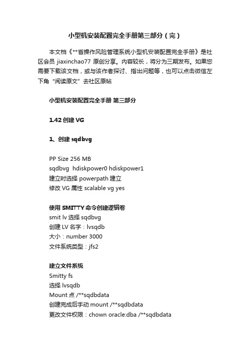
如果您需要下载该文档,或与该作者探讨、指出问题等,也可以点击微信左下角“阅读原文”去社区原帖小型机安装配置完全手册第三部分1.42 创建VG1、创建sqdbvgPP Size 256 MBsqdbvg hdiskpower0 hdiskpower1建立时选择 powerpath建立修改VG属性 scalable vg yes使用SMITTY命令创建逻辑卷smit lv选择sqdbvg创建LV名字:lvsqdb大小:number 3000文件系统类型:jfs2建立文件系统Smitty fs选择 lvsqdbMount点 /**sqdbdata创建完成后手动mount /**sqdbdata更改文件权限:chown oracle:dba /**sqdbdata因为2号机需要进行导入操作,必须让1号机释放对硬盘的读写控制,在1号机上输入下列命令:umount /**sqdbdatavaryoffvg sqdbvg 后如果2号机上认到的存储盘没有PVID ,需要把认到的磁盘删掉,然后使用cfgmgr重新扫描, PVID会自动添加。
敲入# smitty vg 后,选择add a volume group,然后建立sqdbvg ,具体配置请按照下面的图示对照填写。
注意:一定要将active volume group automatically 设置为YES。
详细操作步骤:(smit方式):# smitty vg→ Add a Volume Group→ Add an Original Volume Group系统进入卷组创建界面,在该界面中输入以下各项:•[VOLUME GROUP name]项:卷组名称。
输入:sqdbvg;•[Physical partition SIZE in megabytes]项:PPS物理单位分区大小设置为:256•[PHYSICAL VOLUME names]项:物理卷组名称,即上面建立的SSA逻辑驱动盘名称。
MACSV系统手册

本手册的目的
本手册用于帮助用户理解 MACS V 系统的整体概貌、基本功能和特性,以及主要技术指标; 运行本系统需要的软件环境,硬件环境以及系统的各项功能。
.
.
目录 第一章 系统概述.............................................................................................................................8
1.1. 概述...........................................................................................................................8 1.2. 系统能力...................................................................................................................9 1.3. MACSV 系统的实时数据流..................................................................................10 1.4. 系统各部分的主要功能......................................................................................... 11
安装与维护手册 VK300 和 VK3000 三口和五口直接操作喷气阀说明书

Installation and Maintenance ManualSeries VK300 and VK3000 3 Port and 5 Port Direct Operating Solenoid ValvesThis Manual should be read in conjunction with the current product CatalogueFor future reference,please keep this manual in a safe placeThese safety instructions are intended to prevent a hazardous situation and/or equipment damage.These instructions indicate the level of potential hazard by label of “Caution”,“Warning”or “Danger”.To ensure safety,be sure to observe ISO4414 (Note1),JIS B 8370 (Note2)and other safety practices.Note 1:ISO 4414:Pneumatic fluid power – Recommendations for the application of equipment to transmission and control systems.Note 2:JIS B 8370:Pneumatic system axiom.CAUTION :Operator error could result in injury orequipment damage.WARNING:Operator error could result in serious injury or loss of life.DANGER :In extreme conditions, there is apossible result of serious injury or loss of life.1.The compatibility of pneumatic equipment is theresponsibility of the person who designs the pneumatic system or decides its specifications.Since the products specified here are used in various operatingconditions,their compatibility for the specific pneumatic system must be based on specifications or after analysis and/or tests tomeet your specific requirements.2.Only trained personnel should operate pneumaticallyoperated machinery and equipment.Compressed air can be dangerous if an operator is unfamiliar with it.Assembly,handling or repair of pneumatic systems should be performed by trained and experienced operators.3.Do not service machinery/equipment or attempt toremove component until safety is confirmed.1) Inspection and maintenance of machinery/equipment shouldonly be performed after confirmation of safe locked-out control positions.2) When equipment is to be removed,confirm the safety processas mentioned above.Switch off air and electrical supplies and exhaust all residual compressed air in the system.3)Before machinery/equipment is re-started,ensure all safetymeasures to prevent sudden movement of cylinders etc.(Bleed air into the system gradually to create back-pressure,i.e.incorporate a soft-start valve).4.Contact SMC if the product is to be used in any of thefollowing conditions:1)Conditions and environments beyond the givenspecifications,or if product is used outdoors.2)Installations in conjunction with atomic energy,railway,airnavigation,vehicles,medical equipment,food and beverage,recreation equipment,emergency stop circuits,press applications,or safety equipment.3)An application which has the possibility of having negativeeffects on people,property,or animals,requiring special safety analysis.Ensure that the air supply system is filtered to 5 micron.ENSURE THAT THE EXHAUST PORTS ARE LEFT OPEN WHEN CONVERTING A VALVE TO 3 PORT CONFIGURATION.VK300-TFM71Specifications Type of operation Direct operated 2-position single solenoid Operating fluid AirStandard Operating pressure rangeVacuum Ambient temperature and operating fluid temperature MAX.50 ºC Standard * Response timeLow wattManual Operation Non-lock push type LubricationUnnecessary Mounting positionAny position ** Impact,vibration resistance 300m/s 2,50m/s ProtectionIP65*In accordance with the dynamic performance test of JIS B 8374-1981 (at the rated voltage,**Impact resistance:No malfunction from test using drop impact tester to axis and right angle direction of main valve and armature,one time when energised and de-energised.Vivration resistance:No malfunction from test with from 8.3 to 2000Hz 1 sweep to axis and right angle direction of main valve andarmature each time when energised and de-energised (Value in the initial stage).Solenoid Specifications Electrical entry DIN type terminal (D)AC Rated voltage DC Allowable voltage ±10%Inrush Apparent power Holding Standard Power consumptionLow watt AC Surge voltage protection circuit Fig 1PlugPlug231425134242513513M3X26Screw W/Spring washer Manifold gasketDXT199-23-4M3X8Screw W/Spring washer Blanking plate VK300-33-3VK3000-7-1Manifold gasket for blanking plateVK3000-6-3M3X26Screw W/Spring washer DXT199-23-4VK3120-OG-01VK3140-OGVK3000-6-1Manifold gasket VK3000-6-2Applicable base Model VV5k3-20Model VV5k3-21Manifold base}Applicable base VK3000-9-1Model VV5k3-40Model VV5k3-(S)41Model VV5k3-(S)42Manifold baseSubplate }(3) Blanking plate Ass’y Parts No.:VK3000-7-1AApplicable base:common for all VV5k3 modelsFig 2(1) Model VK332(2) Model VK334M3X26Screw W/Spring washerManifold gasket DXT199-23-4M3X26Screw W/Spring washer DXT199-23-4VK332-OG-01VK334-OGVK300-41-1VK300-33-3Manifold gasketVK300-41-2Applicable base Model VV3k3-20Model VV3k3-21Model VV5k3-20Model VV5k3-21Manifold baseManifold baseSubplate }Applicable baseVK300-45-1Model VV3k3-40Model VV3k3-(S)42Model VV5k3-40Model VV5k3-(S)41Model VV5k3-(S)42(3) Blanking plate Ass’y Parts No.:VK300-42-1A M3X8Screw W/Spring washer VK300-42-1Blanking plate VK300-41-3Manifold gasket for blanking plateApplicable base:common for all VV3k3 models}Mixed Mounting of VK300 Series and VK3000 Series (Fig 4)It is possible to mount the VK300 onto the Manifold base of the VK3000 Series.When specifying VV5K3-20 or VV5K3-40,ensure that theappropriate Exhaust Port on the Manifold base is PLUGGED using a rubber plug part No.VK3000-8-1,as this Exhaust port becomes redundant when mounting 3 port Valves.The 3 port Valve can also be mounted on additional Manifolds i.e.VV5K3-21,VV5K3-(S)41 and VV5K3-(S) 42 without additional modifications.CAUTION•When converting a 5 port Valve,from 3 ports back to 5 ports ensure that the exhaust plug is removed.•When a 3 port Valve (VK300) is Mounted onto the Manifold base of the VK3000 Series,the Valve function will be NORMALLY CLOSED.If a NORMALL Y OPEN function is required plug port No.of a 5 port Valve.•When piping from the Manifold base,the port No.Valve becomes the port No.4 of the 5 port Valve.possibility of incorrect piping to the port No.port No.2 is plugged.Model VV5K3-20VK332-OG-01VK3120-OG-01Plug VK3000-8-1Plug VK3000-8-1Notch mark (Recession)Notch mark (Recession)VK334-OGModel VV5K3-40VK3140-OGConnection Method for Lamp/Surge Voltage Protection Circuit (Fig 7)When using a DIN connector with DC voltage connect the positive side (-) to the symbol 2 of the terminal block.Part No.of the connector without lamp:VK300-82-1Part No.of the connector with lamp:Refer to the following table Rated voltage *Marking Parts No.AC100V 100V VK300-82-2-01AC110V 110V VK300-82-2-03AC200V 200V VK300-82-2-02AC220V 220V VK300-82-2-04AC240V 240V VK300-82-2-07DC6V 6V VK300-82-4-51DC12V 12V VK300-82-4-06DC24V 24VD VK300-82-3-05DC48V48VDVK300-82-3-53*Indicated on the terminal block.Changing the Direction of the Connector (Cable)After separating the Terminal block from the housing,the cable direction can be changed 4 ways at 90º intervals.WARNINGIf the connector is fitted with a lamp,ensure that the lamp is not damaged by the lead wire of the cable.Applicable Cable.( 2 conductors or 3* conductors)Outside diameter of the cable should be ø3.5 ~ ø7mm.Note 3 Conductor cables are used when connecting to Ground.CAUTIONEnsure that the connector is straight during insertion or removal.Piping tightening torque Connecting screwAppropriate tightening torqueN•m {kgf•cm}M5 1.5~2{15~20}Rc (PT) 1/87~9 {70~90}LubricationThe valve has been lubricated for life on assembly and requires no additional lubrication.element.Keep the residual leakage voltage to 20% or less of the rated voltage for AC coils and 2% or less of the rated voltage for DC coils.MaintenanceWARNINGWhen changing the rated voltage the valve MUST be replaced,as it is NOT possible to change the coil.It is NOT possible to dismantle the valve due to its design.Application of undue force to the valve may damage the valve section.Neon glow lamp with DC,connect the positive side to the Red lead wire and the Negative side to the Black the Blue lead wire is for 100VAC,and the Red Fig 7Varistor Varistor LED LED V a r i s t o rNo.1No.2No.2No.1(+)No.2(-)DiodeNo.1(+)2D i o d eRed (+)Black (-)Surge voltage protection circuitFig 9When you enquire about the product,please contact the following SMC Corporation :ENGLAND Phone 01908-563888TURKEY Phone 212-2211512ITALY Phone 02-92711GERMANY Phone 6103-402-0HOLLAND Phone 020-*******FRANCE Phone 01-64-76-10-00SWITZERLAND Phone 052-396 31 31SWEDEN Phone 08-603 07 00SPAIN Phone 945-184100AUSTRIA Phone 02262-62-280Phone 902-255255IRELAND Phone 01-4501822GREECE Phone 01-3426076DENMARK Phone 70 25 29 00FINLAND Phone 09-68 10 21NORWAY Phone 67-12 90 20BELGIUM Phone 03-3551464POLAND Phone 48-22-6131847PORTUGAL Phone 02-610 8922*Marking*MarkingFor AC and DC 12V or less For DC 24V or moreLight (built in connector)Surge voltage protection circuit (built into the terminal block)AC circuit drawingNL:Neon lamp R:ResistorDC circuit drawing 12V or lessLED:Light emitting diode R:ResistorDC circuit drawing 24V or moreD:Protective diodeLED:Light emitting diode R:Resistor*C o n t a c t p o i n tC -R e l e m e n tCurrent leakageVoltage leakageValvePower sourceC o i lC o i lCoilCoil CoilCoil No.1No.2No.1No.2No.1Neon glow lamp DiodeD i o d eNo.2No.12No.1V a r i s t o rFig 6Fixing screwHousing(Code)Refer to table below Terminal screw (3 places)Slotted area(Light installation position)Terminal block Grommet (Rubber)WasherGland nut。
SMC 产品说明书
Other SettingsSummary of Product partsSimple Setting ModeTroubleshootingNote: Specifications are subject to change without prior notice and any obligation on the part of the manufacturer.© 2015 SMC Corporation All Rights ReservedAkihabara UDX 15F, 4-14-1, Sotokanda, Chiyoda-ku, Tokyo 101-0021, JAPANPhone: +81 3-5207-8249 Fax: +81 3-5298-5362URL Specifications/Outline with Dimensions (in mm)Refer to the product catalogue or SMC website (URL ) formore information about the product specifications and outline dimensions.PS※※-OMS0008-A InstallationMounting with bracketMount the bracket to the body with mounting screws (Self tapping screws:Nominal size 3 x 8L (2 pcs)), then set the body to the specified position.∗: Tighten the bracket mounting screws to a torque of 0.5±0.05 Nm.Self tapping screws are used, and should not be re-used several times.∗: The panel mount adapter can be rotated through 90 degrees for mounting.•Bracket A (Part No.: ZS-46-A1)•Bracket B (Part No.: ZS-46-A2)Mounting with panel mount adapterMount part (a) to the front of the body and fix it. Then insert the body with (a)into the panel until (a) comes into contact with the panel front surface. Next,WiringWiring connectionsConnections should be made with the power supply turned off.Use a separate route for the product wiring and any power or high voltagewiring. Otherwise, malfunction may result due to noise.If a commercially available switching power supply is used, be sure toground the frame ground (FG) terminal. If the switching power supply isconnected for use, switching noise will be superimposed and it will not beable to meet the product specifications. In that case, insert a noise filtersuch as a line noise filter/ferrite between the switching power supplies orchange the switching power supply to the series power supply.How to use connectorstraight out.OUT1NCNCDC(-)PipingTightening the connection threadFor connecting to the body (piping specification: -M5)After hand tightening, apply a spanner of the correctsize to the spanner flats of the piping body, and tightenwith a 1/6 to 1/4 rotation.As a reference, the tightening torque is 1 to 1.5 Nm.(When replacing the piping adapter ZS-39-N∗, tighten itusing the same method.)Piping specification: -01, -N01After hand tightening, hold the hexagonal spanner flatsof the pressure port with a spanner, and tighten with 2 to3 rotations.As a reference, the tightening torque is 3 to 5 Nm.When tightening, do not hold the Z/ISE20 body with aspanner.Default settingsWhen the pressure exceedsthe set value, the switch will beturned on. When the pressurefalls below the set value by theamount of hysteresis or more,the switch will be turned off.The default setting is to turn onthe pressure switch when thepressure reaches the centre of the atmospheric pressure and upper limit of therated pressure range. If this condition, shown to the right, is acceptable, then keepthese settings.Error indication functionThis function is to display error location and content when a problem or error has occurred.than above are displayed, please contact SMC.Refer to the SMC website (URL ) for more informationabout troubleshooting.button between1 and 3 sec.button between3 and 5 sec.∗:The outputs will continue to operate during setting.∗:If a button operation is not performed for 3 seconds during the setting, the display will flash.(This is to prevent the setting from remaining incomplete if, for instance, an operator were to leaveduring setting.)∗:3 step setting mode, simple setting mode and function selection mode settings are reflected eachother.[3 step setting mode (hysteresis mode)]orsetting can be changed in the same way.button once when the item toThe set value on the sub display (right) willstart flashing.orbutton and can be reduced withbutton.buttons are pressed and held simultaneously for 1second or longer, the set value is displayed as [- - -], and the set value will bethe same as the current pressure value automatically (snap shot function).button.button to complete the setting.The Pressure switch turns on within a set pressure range (from P1L to P1H) duringwindow comparator mode.Set P1L, the lower limit of the switch operation, and P1H, the upper limit of theswitch operation and WH1 (hysteresis) following the instructions given above.(When reversed output is selected, the sub display (left) shows [n1L] and [n1H].)∗:Setting of the normal/reverse output switching and hysteresis/window comparator modeswitching are performed with the function selection mode [F 1] OUT1 setting.valuePeak/bottom value indicationbutton inmeasurement mode.Snap shot functionbuttons for 1second or longer simultaneously. Then, the set value of the sub display (right)shows [- - -], and the values corresponding to the current pressure values areautomatically displayed.Zero-clear functionbuttons are pressed for 1 secondor longer simultaneously, the main display shows [- - -], and the reset to zero.The display returns to measurement mode automatically.Key-lock functionTo set each of these functions, refer to the SMC website(URL ) for more detailed information, or contact SMC.button between 1 and 3 seconds inmeasurement mode. [SEt] is displayed on the main display. Whenthe button is released while in the [SEt] display, the current pressurevalue is displayed on the main display, [P_1] or [n_1] is displayed onthe sub display (left), and the set value is displayed on the subdisplay (right) (Flashing).or button to set the(The snap shot function can be used.)or button to set the(The snap shot function can be used.)or button, the delay time of the switch output can be selected.button for 2 seconds or longer to complete the OUT1 setting.∗:If the button is pressed for less than 2 seconds, the setting will be returned to P_1.In the window comparator mode, set P1L, the lower limit of the switch operation,and P1H, the upper limit of the switch operation, WH1 (hysteresis) and dt1 (delaytime) following the instructions given above.(When reversed output is selected, the sub display (left) shows [n1L] and [n1H].)Function selection modebutton between 3 and 5seconds, to display [F 0]. Select todisplay the function to be changed[F]. Press and hold the buttonfor 2 seconds or longer in functionselection mode to return tomeasurement mode.∗:Some products do not have all the functions. If no function is available or selected due toconfiguration of other functions, [- - -] is displayed on the sub display (right).Names of individual partsRefer to the product catalogue or SMC website (URL )for more information about panel cut-out and mounting hole dimensions.Pressure Setting3 Step Setting Mode(URL ) for more detailed information, or contact SMC.MaintenanceHow to reset the product after a power cut or forcible de-energizingThe setting of the product will be retained as it was before a power cut orde-energizing. The output condition is also basically recovered to that before apower cut or de-energizing, but may change depending on the operatingenvironment. Therefore, check the safety of the whole installation before operatingthe product. If the installation is using accurate control, wait until the product haswarmed up (approximately 10 to 15 minutes).Safety InstructionsBefore UseDigital Pressure SwitchZSE20(F)/ISE20Thank you for purchasing an SMC ZSE20(F)/ISE20 Series Digital PressureSwitch.Please read this manual carefully before operating the product and make sure youunderstand its capabilities and limitations. Please keep this manual handy forfuture reference.Safety InstructionsThese safety instructions are intended to prevent hazardous situations and/orequipment damage.These instructions indicate the level of potential hazard with the labels of"Caution", "Warning" or "Danger". They are all important notes for safety and mustbe followed in addition to International standards (ISO/IEC) and other safetyregulations.OperatorSwitch ONAt normal output Switch OFFSet valueP_1HysteresisH_1TimePressureOther parameter settingsDefault settingThe default setting is as follows.If no problem is caused by thissetting, keep these settings.。
安装手册说明书
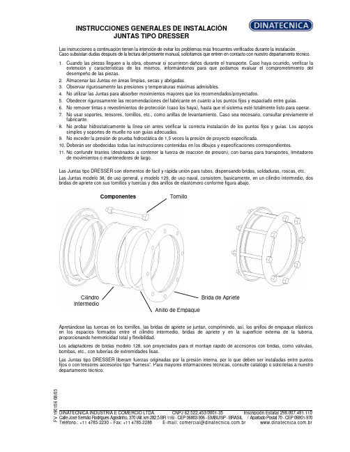
INSTRUCCIONES GENERALES DE INSTALACIÓN JUNTAS TIPO DRESSERLas instrucciones a continuación tienen la intención de evitar los problemas más frecuentes verificados durante la instalación. Caso subsistan dudas después de la lectura del presente manual, solicitamos que entren en contacto con nuestro departamento técnico.1. Cuando las piezas lleguen a la obra, observar si ocurrieron daños durante el transporte. Caso haya ocurrido, verificar la extensión y características de los mismos, informándonos para que podamos evaluar el comprometimiento del desempeño de las piezas.2. Almacenar las Juntas en áreas limpias, secas y abrigadas.3. Observar rigurosamente las presiones y temperaturas máximas admisibles.4. No utilizar las Juntas para absorber movimientos mayores que los recomendados/proyectados.5. Obedecer rigurosamente las recomendaciones del fabricante en cuanto a los puntos fijos y espaciado entre guías.6. No remover tintas o revestimientos de protección (caso los haya), hasta que el sistema esté totalmente listo para operar.7. No usar soportes, tensores, tornillos, etc., como anillas de levantamiento. Caso sea necesario, consultar previamente el fabricante.8. No probar hidrostaticamente la línea sin antes verificar la correcta instalación de los puntos fijos y guías. Los apoyos simples y soportes de muelle no son guías adecuadas.9. No exceder la presión de prueba hidrostática de 1,5 veces la presión de proyecto especificada.10. Deberán ser obedecidas todas las instrucciones contenidas en los dibujos y especificaciones correspondientes.11. No confundir tirantes (destinados a contener la fuerza de reacción de presión), con barras para transportes, limitadores de movimientos o mantenedores de largo.Las Juntas tipo DRESSER son elementos de fácil y rápida unión para tubos, dispensando bridas, soldaduras, roscas, etc. Las Juntas modelo 38, de uso general, y modelo 129, de uso naval, consistem, basicamente, en un cilindro intermedio, dos bridas de apriete con sus tornillos y tuercas y dos anillos de elastómero conforme figura abajo.Componentes Apretándose las tuercas en los tornillos, las bridas de apriete se juntan, comprimindo, así, los anillos de empaque elásticos en los espacios formados entre el cilindro intermedio, bridas de apriete y en la superficie externa de la tubería, proporcionando hermeticidad total y flexibilidad.Los adaptadores de bridas modelo 128, son proyectados para el montaje rápido de accesorios con bridas, como válvulas, bombas, etc., con tuberías de extremidades lisas.Las Juntas tipo DRESSER liberam fuerzas originadas por la presión interna, por lo que deben ser instaladas entre puntos fijos o con tensores accesorios tipo “harness”. Para mayores informaciones técnicas, consulte catálogo o solicítelas a nuestro departamento técnico.F V 190106 08/05 DINATECNICA INDUSTRIA E COMERCIO LTDA. CNPJ 62.522.453/0001-35 Inscripción Estatal 298.007.491.110 Calle José Semião Rodrigues Agostinho, 370 (Alt. km 282,5 BR 116) - CEP 06803-906 - EMBU/SP - BRASIL / Apartado Postal 70 - CEP 06801-970Teléfono.: +11 4785-2230 – Fax: +11 4785-2288 E-mail:*************************.br .brTornilloBrida de Apriete Anillo de EmpaqueCilindro IntermedioINSTRUCCIONES GENERALES DE INSTALACIÓN JUNTAS TIPO DRESSERTipos 38 y 129 ESQUEMA DE MONTAJELimpiar los extremos de los tubos que serán acoplados (aprox.200 mm en cada extremo). Remover completamente cualesquiera oleosidades, rebarbas, salpicaduras de soldadura, etc., de tal forma que los tubos queden limpios y sin ningún saliente que pueda perjudicar el montaje y performance de la Junta. Recomendamos que, después de limpiar los anillos de empaque y, antes del montaje del sistema, sean imersos en una solución de água y jabón (y glicerina, tratándose de temperaturas abajo de 0°C), lo que facilitará el montaje de los mismos.Colocar las bridas de apriete, deslizándolas en el área limpia de los tubos. Posicionar los anillos de empaque cerca de las bridas (uno en cada extremo del tubo).Limpiar bien el cilindro intermedio, poniendo particular atención en los extremos donde asentarán los anillos de empaque. Colocar el cilindro intermedio sobre uno de los tubos terminales.Aproximar el otro terminal hasta conseguir que entre los dos extremos se establezca una holgura de 13mm (tipo 38), y de 13 mm + diámetro del “pipe-stop” (tipo 129). Esta holgura permite la absorción de la dilatación de la línea.Una vez completada la centralización, deslize los anillos de empaque y bridas de apriete contra los extremos (asientos) del cilindro intermedio hasta que se produzca el encaje de los mismos.Insertar los tornillos. Ajustar las tuercas manualmente hasta que se recuesten en las bridas.El apriete final deberá ser dado con dos llaves fijas, una produciendo el torque y otra impidiendo el giro del tornillo.El apriete deberá ser realizado en forma intercalada con fuerza progresiva, hasta conseguir que todos los tornillos tengan un ajuste uniforme. Si en la prueba hidrostática surgiesen escapes, deberá darse un sobre-apriete uniforme, progresivamente, hasta que la prueba presente resultado satisfatório.Cuando haya “pipe-stops”, estos deberán ser retirados antes de la instalación y recolocados después de su finalización.Tipo 128 Deben seguirse los mismos cuidados para los tipos 38 y 129, sin embargo, considerándose que uno de los terminales es parte integrante de la Junta, lo que facilitará su instalación.a) Antes de, eventualmente, modificar cualesquiera de nuestras instrucciones, solicitamos consultarnos. NOTAS: b) Nuestra garantía no cubre daños ocurridos por el incumplimiento de cualesquiera de las recomendaciones aquí expuestas, sin nuestro previo consentimiento.F V 190106 08/05DINATECNICA INDUSTRIA E COMERCIO LTDA. CNPJ 62.522.453/0001-35 Inscripción Estatal 298.007.491.110 Calle José Semião Rodrigues Agostinho, 370 (Alt. km 282,5 BR 116) - CEP 06803-906 - EMBU/SP - BRASIL / Apartado Postal 70 - CEP 06801-970Teléfono.: +11 4785-2230 – Fax: +11 4785-2288 E-mail:*************************.br .br。
Vservice操作维护手册范本

BISCVService操作维护指导书国际交换系统技术事业部二零零四年四月目录0 一般信息0.1 发行说明本手册(含封面)共13页,所有页的发行号都为01。
0.2 历史0.3 外部的商标和Linux 商标属于 Linus Torvalds 先生所有。
Solaris是 Sun Microsystems, Inc. 在美国和其它国家/地区的商标或注册商标。
"redhat" 及Red Hat"shadow man"图标是Red Hat在美国及其它国家/地区的商标或注册商标。
DB2、IBM 是 IBM 公司在美国和/或其它国家或地区的商标或注册商标。
其它公司、产品和服务名称可能是其它公司的商标或服务标记。
0.4 简写和缩略语CCF 呼叫控制功能CS—1 (智能网)能力集1CS—2 (智能网)能力集2DTMF 双音多频FEAM 功能实体接入管理IN 智能网INAP 智能网应用规程IP 智能外设ISUP ISDN用户部分MML 人机语言RM 资源管理SCEP 业务生成环境点SCF 业务控制功能SCC 业务控制点SDF 业务数据功能SDL 规和描述语言SDP 业务数据点SMAP 业务管理接入点SMF 业务管理功能SMC 业务管理点SRF 专用资源功能SSF 业务交换功能SSP 业务交换点TCAP 事务处理能力应用部分0.5 图表1 VService-SCC设备的维护1.1 系统进程➢I2NDAEMON进程是SCC系统守护进程,监视SCC其他进程的运行状态,当被监视进程发生异常时采取措施或重新创建问题进程。
启动VSERVICE-SCC系统时,可以直接运行I2NDAEMON进程,当I2NDAEMON发现其他进程没有启动时,会自动启动所有需要的SCC进程。
➢CONCENTER进程CONCENTER进程在SCC系统运行过程中起着非常重要的作用。
⏹该进程负责各功能实体间的消息传递,实现网络通信和进程间通信。
SMC 电子控制气体阀门用户手册说明书
Minimum operating pressure
Single Double (double solenoid) 3 position 4 position
Ambient and fluid temperature
0.1 MPa
0.15 MPa
0.1 MPa
0.1 MPa
0.1 MPa
0.2 MPa
Danger
Danger indicates a hazard with a high level of risk which, if not avoided, will result in death or serious injury.
Warning
• Always ensure compliance with relevant safety laws and standards.
SMC伺服模块说明书-中文
SERVO-P PackageXT581-SP-A/B/C-IRD-ESERVO-P CylinderXT581C125-H063-140P XT581C140-H064-140P XT581T100-H079-90P XT581T125-H065-90P XT581T140-H060-90P XT581T160-H066-90P XT581B80-H061-150P XT581B90-H072-150P XT581B100-H076-160P XT581B125-H077-160P操作手册产品型号型号/系列产品型号型号/系列 (4) (8)............................................................................................................9 ............................................................................10 . (11)...........................................................................................................11 .........................................................................................................12 (13) (14)....................................................................................................14 . (15)...........................................................................................................................17 . (20) (20).........................................................................................................................22 ..........................................................................................................23 . (25) (26).....................................................................................................................26 .................................................................................................................................27 . (28) (30) (30) (31) (35).....................................................................................................38 (39) (40).................................................................................................40 . (40) (41)目录1.安全2.产品简介......................................................................................82.1.产品特性2.2.SERVO-P系统结构3.产品规格4.组件介绍4.1.SERVO-P气缸简介4.2.平衡缸简介4.3.SERVO-P模块简介5.安装及试运行操作设置5.1.试运行操作设置5.2.安装5.3.配线及配管6.调试6.1.开关设定6.2.程序数据6.3.进程分配6.4.总线错误处理7.SERVO-P模块XT581-SP-A/B/C-IRD-E7.1.零部件及描述7.2.产品规格7.3.LED指示灯表示8.SERVO-P模块尺寸9.1.SERVO-P模块LED指示灯状态.....................................................................................................358.1.SERVO-P模块尺寸8.2.SERVO-P伺服气缸尺寸9.错误处理9.2.S总线传输状态9.3.SERVO-P系统错误信息10.备用物品10.1.密封件,传感器单元,伺服电磁阀10.2.其他备用物品11.附录1 SERVO-P模块电气回路 (42)......................................................................................42 .................................................................................................................................43 ................................................................................................................................44 (45)............................................................................46 ........................................................................47 ......................................................................................48 .........................................................................................................48 ...............................................................49 .................................................................................................................................50 (51)............................................................................52 12.附录2 I/O Map 解析及时间图表12.1.焊枪代码,工具转换支持12.2.E-Stop值12.3.无压力状态12.4.复位运动12.5.位置/压力运动,位置运动可能12.6.手动控制平衡缸运动12.7.修模及更换12.8.SERVO-P气缸压力12.9.设置正确的SERVO-P气缸缸径参数12.10.焊枪速度设定12.11.平衡缸压力设定12.12.目标位置设定及位置信号反馈♦♦♦♦♦♦1*1: •• *2*3.*2:•••*3: ♦1.安全此手册中包含了防止操作者,其他人员或设备财产受到损害的重要信息。
安装、操作和维护手册说明书

Installation and Operation Manual Installation, Operation and Maintenance Manual DFOE3, DFOE4, DFOE6Throughout this manual statementsindicating precautions necessary to avoid equipment failure are referenced in a Note. Statements indicating potential hazards that could result in personal injury or property damage are referenced in a CAUTION! box.Donaldson Company reserves the right to change designand specifications without prior notice.Illustrations are for reference only as actual product mayvary.IOM AK0302801Revision1 DFOE4DFOE3 DFOE6唐纳森(无锡)过滤器有限公司Donaldson (Wuxi) Filters Co.,Ltd.Warning – Improper operation of a dust control system may contribute toconditions in the work area or facility that could result in severe personal injury and product or property damage. Check that all collection equipment is properly selected and sized for the intended use.DFOE3,4,6 Table of contents List of figures1.0 Product Introduction …………………….6 Figure 1: Schematic2.0 Installation……………………………….6 Figure 2: Operational Schematic3.0 Start up and Operation …………………7 Figure 3: Inlet Schematic4.0 Service …………………………………...8 Figure 4: Dust Removal for Dust DisposalSystem5.0 Trouble Shooting ………………………...9 Figure 5: Exchanging Filter Element6.0 Control Panel ……………………………11 Figure 6: Control Panel7.0 Spare Parts ………………………………15 Figure 7: Electrical Terminal BlockFigure 8: Wiring DiagramData SheetModel Number __________________________Serial Number_____________________________ Ship Date _______________________________Installation Date __________________________ Customer Name________________________________________________________________ Address _______________________________________________________________________ _______________________________________________________________________ Filter Type _____________________________________________________________________ Accessories_____________________________________________________________________ Other _________________________________________________________________________唐纳森(无锡)过滤器有限公司Donaldson (Wuxi) Filters Co.,Ltd.DFOE4DFOE3Figure 1 Schematic1. Lift bar2. Filter access cover3. Dust bin4. Control panel5. Access door6. Inlet7. Access panel for cleaning 8. Fan outlet9. Power supply cable inlet 10. Compressed air inletDFOE 3,4,6*Figure 2Operational SchematicOperation Filter element cleaning 4. Clean air outlet 5. Manifold 7. Tube sheet 1.Dirty air inlet唐纳森(无锡)过滤器有限公司Donaldson (Wuxi) Filters Co.,Ltd.1.0 Product Introduction The dust collector is used for the collection of airborne dust and particulate. Whether in answer to the problem of air pollution, or as part of a manufacturing process, the dust collector provides highly efficient and continuous on-line dust collection. The filter elements are the heart of the dust collector. These filter elements help ensure the only cleaned air is returned to the plant environment. During operation, contaminated air enters the dust collector through the dirty air inlet area and passes through the filter elements. Dust is collected on the surface of the filterelements. The filtered air flows through the centre of the filter elements into the clean air chamber, where it exhausts through the clean air outlet re-circulated into the environment. To ensure the optimal performance of your dust collector it is necessary that the filter elements are cleaned automaticallysequentially. During the filter sequence, the timer energizes a solenoid valve, causing the corresponding diaphragm valve to send a pulse of compressed air through the filter elements (from the inside outwards),removing the collected dust from the outside surface of the filter elements. The dust falls through the hopper into the dust disposal system.2.0 InstallationEnsure all persons carrying out work on thesupplied equipment follow any relevant recognized standards or codes and are competent to do so.2.1 Compressed Air ConnectionCompressed air pressure must be at 6 bar. Be sure that all compressed air components are adequately sized to meet the maximum system requirements of 45 Nliters per pulse at 6 bar supply pressure (= design pressure).Compressed air supply has to be both oil and moisture free.Connect the compressed air supply line to the compressed air connection of the dust collector.A compressed air shut-off valve, a filter/water separator with automatic condense drain, a pressure regulator with gage must beinstalled on the compressed air supply line.2.2 Electrical ConnectionEnter the cable through the cable gland locate at the lower right corner of thecollector. And enter the cable to the control box through the cable gland locate at the bottom of the enclosure. Please follow the electrical diagram provided for connection. Do not install in classified hazardousatmospheres without an enclosure rated for the application.DFOE 3,4,6Figure 3 Inlet Schematic2.3 Inlet Duct ConnectionThe inlet collar is integrated with the unit, it isshown on figure 3.3.0 Start-up and OperationCheck that the outlet of the fan is free of debris before starting.Make sure the dust disposal system is properly installed under the hopper.With new filter elements the airflow should be adjusted to the nominal value by closing the damper valve.Check if the access doors are closed. Switch main power on and press switch ’start’.Adjust the damper to the desired airflow. Turn on the compressed air supply. Adjust to 6 bar of pressure with the compressed air regular.The cleaning cycle only starts whennecessary. For customized setting see the controls manual.唐纳森(无锡)过滤器有限公司Donaldson (Wuxi) Filters Co.,Ltd.Figure 4Dust Removal for Dust Disposal SystemFigure 5Replacing of Filter ElementsWhen replacing diaphragm assembly make sure the marking "THIS SIDE OUT" ondiaphragm assembly faces valve bonnet and that bleed hole in diaphragm assembly is in alignment with cavity in valve body and bonnet. The external contours of thediaphragm, body and bonnet must all be in alignment.Replace bonnet bolts and tighten in a criss-cross manner.4.2 Replacing of Filter ElementsCaution :When the airflow is low or the differential pressure is too high and alarm, must change the filter elements. After operating more than 2000—4000 hours continuously, must change the filter elements.All filter elements should be changed at the same time.Do not drop the new filter element on the floor or any other hard surface. It isnecessary to clean the dust of the tube sheet all around the opening to ensure a positive seal of the gasket.Slide the new filter element along the yoke with the gasket end facing inward towards the clean air chamber.Reinstall the cover and screw the wing nut clockwise onto the yoke. Tighten securely, to prevent leakage.DFOE3,4,6 5.0 Trouble shooting唐纳森(无锡)过滤器有限公司Donaldson (Wuxi) Filters Co.,Ltd. Fan does not startNot wired correctly.Check and correct internal motor wiring forproper connections for your voltage (see Wiring Diagram)Proper wire size not used for motor Rewire per national and local electric codes for proper wire size. Fan set starts, butdoes not keep running Incorrect overload protection is installed Check for proper motor overload protection. Reset or replace if needed for proper value.Dust collector doors are open or not closed tight Tighten doors securely.Hopper open to atmosphereInstall dust bin under hopper and seal the access door securely.Damper valve not adjusted properlyCheck airflow in ducting for properrequirements. Adjust the damper valve until the proper airflow is achieved. Do not attempt to run without inlet ducting attached.Electrical circuit fusesCheck if the supply circuit has sufficient power to run all equipment. Excessivenoise/vibration of the fanIf thishappens, it should be rectified at onceDust deposit on the blades Clean the blades.Worn blades The fan wheel has to be replaced. Worn bearingsThe bearings have to be replaced.Dust emissionFilter elements installed improperlyCheck that gaskets on the filter element(s) are firmly pressed to the tube sheet (the wing nuts of the filter elements should befully tightened by hand).Filter element damage, dents in the end caps, gasket damage or holes in pleated media Replace the filter elements.Doors not airtightTighten doors securely and check sealing.DFOE3,4,6Insufficient airflow Fan wheel rotating wrongway Check fan rotation. Refer to rotation sticker on fan housing.Openings not properly sealed Check doors, that they are closed and tightened securely. Also check hopper area that openings are closed off and that the hopper dust disposal is installed.Outlet is restricted Check outlet for blockage. Removematerial or debris that is blocking the outlet. Filter elements plugged :a. Lack of compressed airb. Pulse cleaning not energizedc. Dust disposal system is too full or pluggedd. Hopper full of dust or pluggede. Filter elements need to be replaced Check compressed air supply for under 6 bar.Refer to the trouble shooting guide from the Control manual.Clean out dust disposal system..Clean out the hopper.Replace the filter elementsSolenoid valves/diaphragmvalves are not functioning: a. Solenoidvalves/diaphragm valves are leaking compressed airb. Pulse control printed circuit board has failed or is out of adjustment Check for debris, obstruction, valve wear or diaphragm failure by removing the diaphragm cover on the solenoid valves. Also check for solenoid leakage damage. If diaphragm valves or solenoid valves are damaged replace it or replace damaged part(s).Refer to Operating manual of the Controls.Excessive noise of a diaphragm valve Failure on the diaphragmvalveCheck for debris, obstruction, valve wear orfailure by removing the diaphragm cover. Ifthe diaphragm valve is damaged, replace itor replace damaged part(s).唐纳森(无锡)过滤器有限公司Donaldson (Wuxi) Filters Co.,Ltd.6.0 Control Panel6.1 Control panel functionsThe “Local/Remote” selection switch is for LOCAL or REMOTE fan motor on/off control selecting. And the control panel also provides one voltage free contact output for indication of fan motor run/stop status.The “Auto/Manual” selection switch for AUTO or MANUAL cleaning control modelselecting. When the selection switch is at the "Manual" position, the collector will clean continually. When the selection switch is at the "Auto" position, the collector cleaning will controlled by the Torit Delta P-C01 controller on the panel, and the control panel can also provide down-time cleaning.Fan motor overload protection and overload indication (Error).6.2 OperationEnsure that the control panel is correctly installed onto the dust collector before starting up (check main power supplyconnections, all electrical cable connections, fan starter/fan motor connections,solenoid/diaphragm valve connections,compressed air tubing connections, etc.) For safety of personnel and equipment, ensure that the control panel is properly grounded. Turn the main power supply switch to"ON" position. The Torit Delta P-C01 controller will power up. All operating instructions for the Torit Delta P-C01 controller are mentioned in a separate manual of Delta P-C01.Figure 6Control PanelDFOE3,4,6•When the “Local/Remote” selection switch is set at “Remote” position, thestart/stop of the fan motor can becontrolled remotely. When the remotecontrol switch is closed the “Running”green indication light will light up and the fan motor will be powered up; when theremote control switch is opened the“Running” green indication light will go off, and the fan motor dis-energized. •When the "Local/Remote" selection switch is set at "Local" position all control operations need to be carried out locallyat the control panel. The fan motor canbe turn on and off by pushing the "FanStart" and "Fan Stop" buttonsrespectively. When push the “Fan Start“ button, the “Running” greenindication light will light up and the fanmotor will be powered up; when push the “Fan Stop” button the “Running” green indication light will go off and the fanmotor dis-energized.•When the "Auto/Manual" selection switch is set at "Manual" position, the cleaningwill process continually. When the"Auto/Manual" selection switch is set at"Auto" position the cleaning will becontrolled by the Torit Delta P-C01controller on the panel. At any timethe cleaning pulse is activated, the“Cleaning” indication light on the panelwill light up. •There is overload protection for the fan motor, the setting of AMPs according tothe nameplate of the fan motor. When the "Error" indication light lights up it signifies that the fan motor is overloaded and hasstopped.•To terminate electrical power supply to the pulsing control, please ensure thatthe fan motor is shut down before turning the main power supply switch to the"OFF" position.唐纳森(无锡)过滤器有限公司Donaldson (Wuxi) Filters Co.,Ltd.Figure 7Electrical Terminal BlockDFOE3,4,6Wiring Diagram唐纳森(无锡)过滤器有限公司Donaldson (Wuxi) Filters Co.,Ltd.ItemDescriptionPart number1 Filter Assembly-Ultra Web FR P19-19202Diaphragm valve with Solenoid Valve8PP- AK00144-21 3 Access cover 3EA-AD33387-01 4 Access door gasket 8PP-AD30021-01 5Delta P-C01 115V/230V8PP-AK01004-007.0 Spare PartsNote: When ordering parts, give model number and serial number of dust collector,description and quantity of parts desired.This Page Intentionally Left BlankDonaldson Company, Inc. is the leading designer and manufacturer of dust, mist, and fume collection equipment used to control industrial-air pollutants. Our equipment is designed to help reduce occupational hazards, lengthen machine life, reduce in-plant maintenance requirements, and improve product quality.© 2015 Donaldson Company, Inc. Printed in APACIOM AK0302801, Revision 1April 2016Parts and ServiceFor genuine Donaldson replacement filters and parts, call the Parts Express Line. For faster service, have unit’s model and serial number, quantity, part number, and description available.The Donaldson Torit WarrantyDonaldson does not warrant against damages due to corrosion, abrasion, normal wear and tear, product modification, or product misapplication. Donaldson also makes no warranty whatsoever as to any goods manufactured or supplied by others including electric motors, fans and control components. After Donaldson has been given adequate opportunity to remedy any defects in material or workmanship, Donaldson retains the sole option to accept return of the goods, with freight paid by the purchaser, and to refund the purchase price for the goods after confirming the goods are returned undamaged and in usable condition. Such a refund will be in the full extent of Donaldson’s liability. Donaldson shall not be liable for any other costs, expenses or damages whether direct, indirect, special, incidental, consequential or otherwise. The terms of this warranty may be modified only by a special warranty document signed by a Director, General Manager or Vice President of Donaldson. Failure to use genuine Donaldson replacement parts may void this warranty. THERE EXIST NO OTHER REPRESENTATIONS, WARRANTIES OR GUARANTEES EXCEPT AS STATED IN THIS PARAGRAPH AND ALL OTHER WARRANTIES INCLUDING M ERCHANTABILITY AND FITNESS FOR A PARTICULAR PURPOSE, WHETHER EXPRESS OR IMPLIED ARE HEREBY EXPRESSLY EXCLUDED AND DISCLAIMED.Donaldson AustralasiaTel: 1800 503 878 (AU)Tel: 0800 743 387 (NZ)Website: www.donaldson f .au Donaldson China Tel: 400 820 1038Website: Donaldson Japan T el: +81 42 540 4114Website: www.donaldson.co.jp Donaldson Korea T el: +82 251 733 33Website: www.donaldson.co.kr Donaldson South Asia T el: +91 124 480 7536Website: Donaldson Southeast Asia T el: +65 6349 8168Website: Donaldson USA T el: +1 800 365 1331Website: Donaldson Europe T el: +32 16 383 811Website: 。
CM-SVC驱动器使用说明书

第一章 安全信息及注意事项
第一章 安全信息及注意事项
安全定义:
1.1.3 配线时:
在本手册中,安全注意事项分以下两类:
由于没有按要求操作造成的危险,可能导 致重伤,甚至死亡的情况
由于没有按要求操作造成的危险,可能导 致中度伤害或轻伤,及设备损坏的情况
1.1 安全事项
1.1.1 安装前:
1.损伤的伺服驱动器及缺件的伺服驱动器请不 要使用,否则有受伤的危险。
1.2.5 伺服驱动器输入、输出端所用接触器等开 关器件
若在电源和伺服驱动器输入端之间加装接 触器,则不允许用此接触器来控制伺服驱动器的 启停。一定需要用该接触器控制伺服驱动器启停 时,间隔不要小于一个小时。频繁的充放电易降 低伺服驱动器内电容器的使用寿命。若输出端和 电机之间装有接触器等开关器件,应确保伺服驱 动器在无输出时进行通断操作,否则易造成伺服 驱动器内模块损坏。
A1 组 PG 卡组 ........................... 56 A2 组 CAN 通讯组 ........................ 57 A3 组 伺服油泵控制组.................... 57 F0 组 基本功能组........................ 60 F1 组 电机参数.......................... 65 F6 组 启停控制.......................... 78 F7 组 键盘与显示........................ 81 F8 组 辅助功能.......................... 83 F9 组 故障与保护........................ 86 FA组 过程控制PID功能(保留) ........... 90 FB组 摆频、定长和计数(保留) .......... 90 FC组 多段速功能及简易PLC功能(保留) ... 90 FD组 通迅参数(保留) .................. 90 FE组 保留功能组(保留) ................ 90 FF组 厂家参数(保留) .................. 90 FP 组 用户密码.......................... 90 第七章 伺服油泵调试步骤及配件选型 ...... 92 7.1 伺服油泵调试流程图.................. 92 7.2 伺服油泵调试步骤 ................... 92 7.3 伺服油泵配件选型 ................... 95 第八章 EMC(电磁兼容性) ............... 98 8.1 定义 ............................... 98 8.2 EMC 标准介绍........................ 98 8.3 EMC 指导............................ 98 第九章 故障诊断及对策 .................. 100 9.1 故障报警及对策 .................... 100 9.2 常见故障及其处理方法 .............. 111 附录 常用参数表 ........................ 112
SMC-2000装置管理系统-用户使用手册

SMC-2000装置管理系统用户手册南京南瑞集团公司信息系统分公司(版权所有翻版必究)目录目录 (2)第一章、产品简介 (4)1.1 简介 (4)1.2 物品清单 (5)1.3 软件使用环境 (5)第二章、软件使用说明 (6)2.1、软件安装 (6)2.2、系统登录 (6)2.3、系统初始化 (9)1、添加CA证书 (10)2、添加OP证书 (10)3、测试硬件 (10)4、修改PIN码 (10)2.4、系统设置 (11)1、设置定时查询和sping时间间隔 (11)2、设置服务器IP (12)3、设置系统名称 (12)4、设置实时画面背景色 (12)5、设置默认布局 (13)2.5、节点管理 (14)1、增加区域节点: (14)2、增加装置节点: (15)3、编辑节点(地区或装置) (16)4、删除节点(地区或装置) (17)5、移动或复制节点 (17)2.6、装置管理 (18)1. 装置查询功能 (18)2. 装置管理功能 (22)3. 其他功能 (28)2.7、系统服务 (31)1、启停定时查询 (31)2、查询系统日志 (32)3、Syslog日志分析 (32)4、装置时间同步 (33)第三章、问题与解答 (34)第四章、客户服务 (35)第一章、产品简介1.1 简介SMC-2000装置管理系统(以下简称SMC)是南京南瑞集团信息系统公司为配合纵向加密认证装置的大规模部署和管理,遵循通用开放、功能齐全、运行稳定、简单易用和跨平台部署的设计原则,自主研制并推出的。
SMC可为电力公司及下属单位所辖的加密认证装置提供集中的、在线的远程安全管理服务,它通过经认证加密的管理报文以在线方式实现对不同厂家的纵向加密认证装置的实时监测和管理。
其部署示意图如下:图1.1 部署示意图1.2 物品清单◆标准1U服务器一台◆电源线两根◆网线一根◆串口线一根◆机箱钥匙一套◆智能卡两张◆使用手册一本◆光盘一张◆物品清单一张◆质检卡一张1.3 软件使用环境软件环境装有Java虚拟机(JDK1.6)的任何操作系统硬件环境CPU:1 GHz 32 位 (x86) 或 64 位 (x64) 内存:512 MB系统内存及以上显卡:标准VGA,24位真彩色其它:光驱、鼠标第二章、软件使用说明2.1、软件安装SMC是基于Java虚拟机(JDK1.6)开发的软件产品,必须运行在Java虚拟机上,所以您的电脑必须先装光盘中附带的JDK1.6版本Java虚拟机。
- 1、下载文档前请自行甄别文档内容的完整性,平台不提供额外的编辑、内容补充、找答案等附加服务。
- 2、"仅部分预览"的文档,不可在线预览部分如存在完整性等问题,可反馈申请退款(可完整预览的文档不适用该条件!)。
- 3、如文档侵犯您的权益,请联系客服反馈,我们会尽快为您处理(人工客服工作时间:9:00-18:30)。
VService-SMC安装手册目录1指定安装计划 (4)1.1确定部署方式 (4)1.2硬件要求 (4)1.2.1内存要求 (4)1.2.2磁盘要求 (4)1.2.3处理器要求 (4)1.3软件要求 (4)1.3.1操作系统环境 (4)1.3.2数据库环境 (5)1.3.3应用服务器环境 (5)1.3.4其他软件环境 (5)2开始安装 (6)2.1安装操作系统 (6)2.1.1安装Redhat Linu x 8.0 (6)2.1.2安装Redhat Advanced Se rve r 2.1 (14)2.2安装数据库 (22)2.2.1修改系统内核参数 (22)2.2.2安装IB M D B2 EE V7.1for Linux (22)2.2.3安装完成后的配置 (30)2.3安装应用服务器环境 (31)2.3.1安装J DK (31)2.3.2安装To mcat (31)2.3.3安装Apache (32)2.3.4安装jk (32)2.4安装SM C软件包 (34)2.4.1创建库表结构 (34)2.4.2安装ja r文件包 (35)2.4.3安装jsp文件 (35)2.4.4铃声分发程序安装................................................................... 错误!未定义书签。
2.4.5参数配置 (35)3常见问题 (40)1指定安装计划1.1确定部署方式SMC业务管理中心在部署时存在两种部署方式:一台服务器完成S MC软件和S MC 数据库部署;两台服务器分别负责部署S MC软件和S MC数据库。
在容量较小时推荐采用第一种方式部署,在系统容量大时推荐采用第二种配置方式。
另外,在某些应用场景时S MC业务管理中心需要配置接入网关服务器(IW G),为VServ ic e平台外部用户提供接口。
但接入网关服务器的安装配置不在此文档内描述。
1.2硬件要求1.2.1内存要求SMC业务管理中心需要根据负载的不同,灵活选择内存容量的配置。
但由于后台数据库I BM D B2 EE V7.1建议内存最小为128MB,所以安装SMC数据库的服务器建议内存不小于128MB。
一般情况下,第一种部署方式推荐配置512MB内存;第二种配置方式SMC服务器和S MC数据库服务器均推荐配置512MB内存。
1.2.2磁盘要求对磁盘的要求主要是S MC数据库服务器的要求(若采用第一种配置方式则为S MC 服务器的要求)。
由于S MC数据库服务器保存了大量业务配置数据和话单数据,因此无论在容量上还是在性能上对磁盘的要求都较高。
建议配置为:S CSI接口的磁盘阵列(配置为RAI D5方式,磁盘可用总空间40G以上,S CS I接口速度160MB/s)。
最小配置为:两块SCS I接口硬盘(单盘容量40G以上),配置为软RAID方式(RAI D 1)。
根据实际情况可选配磁带机(需第三方软件支持数据写入磁带机)。
1.2.3处理器要求处理的性能和个数直接影响数据库查询的性能,S MC业务管理中心应根据负载(使用业务管理中心的用户数量)不同配置不同主频、个数的处理器。
1.3软件要求1.3.1操作系统环境目前SMC业务管理中心支持如下操作系统:操作系统说明Re d Hat Linu x 8.0需要额外安装libstdc++2.90;配置默认语言为中文;Re d Hat Adv anc ed S erv er 2.1配置默认语言为中文1.3.2数据库环境目前数据库仅支持I BM D B2 EE V7.1(F ixP ak3)。
1.3.3应用服务器环境应用服务器环境支持软件如下表所示:软件名称说明下载位置Jdk1.3.1或更高版本Java 开发包http://java.su n.c om/http://jakar ta.ap ac / Tomc at4.0.6或更高版本Serv let/JSP容器软件,目前仅有4.0.6版本进行过测试http://w w w.apac / Apac h e1.3.27Http服务器,Ap ac he2未进行测试,所以只能选择1.3.27jk Apac he和Tomc at的http://jakar ta.ap ac /c onnec tor1.3.4其他软件环境其他需要的支持软件如下表所示:软件名称说明下载位置bash-2.05-8Bash Re d Hat安装光盘v ix ie-c ron-3.0.1-63Cron d服务Re d Hat安装光盘c rontabs-1.10-1tar-1.13.25-8压缩工具Re d Hat安装光盘nc ompress-4.2.4-31g++2.96或更高版本GCC编译器Re d Hat安装光盘1.4对客户端的要求客户端无需单独安装任何软件,只要保证安装了I E即可。
IE的版本建议使用I E6或更高版本,I E6以下版本可能会引起界面显示上的错误。
另外,如果客户端安装了防火墙软件,请在使用SMC业务管理系统时关闭。
因为,系统可能会受到防火墙的影响而出现问题。
1.5对SCC的要求要求SCC侧数据库版本必须与SMC侧数据库版本一致,另外系统默认语言必须为简体中文。
2开始安装2.1通用安装操作2.1.1安装操作系统2.1.1.1安装Re dhat Linu x 8.0首先将安装光盘放入光驱,并设置计算机由光驱启动后启动计算机。
系统直接进入安装界面:直接按回车键后系统会提示检测光盘是否可读,若确定你的光盘没有划伤跳过此步骤即可。
系统进入安装欢迎界面,如下图:点击N ext按钮进入安装语言选择界面,选择语言为简体中文,如下图:类型,采用默认值即可。
接着安装进程会询问用户安装方式,如下图:下图:用户可根据自己情况进行分区,不过建议交换分区大小为1-2倍的物理内存大小。
完成分区后系统会继续要求用户配置启动方式,采用系统默认值即可。
之后配置网络,请按照实际环境配置。
再接着是安装中第1处需要注意的地方,配置防火墙,如下图:防火墙配置请设置为无防火墙。
接下来是配置系统语言支持,如下图:此处是安装中第2处需要注意的地方,请务必选择默认语言为简体中文。
接下来是时区选择、创建帐号和验证配置,按照需要配置即可。
再接下来是选择安装的程序包,请选择如下程序包进行安装,其他程序包不要安装:X窗口系统GNO ME桌面环境编辑器服务器配置工具FTP服务器网络服务器开发工具系统工具如下图所示:接下来系统将复制文件到硬盘,以后的操作请自行完成即可。
但请注意在选择启动方式时选择文本方式(T EXT)启动以节省系统资源。
2.1.1.2安装Re dhat A dv ance d Se rve r 2.1首先将安装光盘放入光驱,并设置计算机由光驱启动后启动计算机。
系统直接进入安装界面:系统进入安装欢迎界面,如下图:点击N ext按钮进入安装语言选择界面,选择语言为英文,如下图:着安装进程会询问用户安装方式,如下图:下图:用户可根据自己情况进行分区,不过建议交换分区大小为1-2倍的物理内存大小。
完成分区后系统会继续要求用户配置启动方式,采用系统默认值即可。
之后配置网络,请按照实际环境配置。
再接着是安装中第1处需要注意的地方,配置防火墙,如下图:防火墙配置请设置为无防火墙。
接下来是配置系统语言支持,如下图:此处请务必选择默认语言为简体中文。
接下来是时区选择、创建帐号和验证配置,按照需要配置即可。
再接下来是选择安装的程序包,请选择如下程序包进行安装,其他程序包不要安装:Class ic X w ind ow SystemX Window Syst emGNO MEAnon ymo us FTP Ser verNetw ork S upp ortUt ilit iesSoftw are Dev e lopm entAdv anc ed S erv er如下图所示:接下来系统将复制文件到硬盘,以后的操作请自行完成即可。
但请注意在选择启动方式时选择文本方式(T EXT)启动以节省系统资源。
2.1.2安装数据库2.1.2.1修改系统内核参数1.以ro ot用户登录系统;2.调整/etc/sysc t l.c onf文件中的参数,增加如下内容:kern e l.c ore_uses_p id = 1kern e l.msgm n i = 512kern e l.sem = 250 12800 32 5123.重新启动系统;2.1.2.2安装IBM D B2 EE V7.1 for Linux1.以ro ot用户登录系统;2.将D B2的安装光盘放入光驱后执行m oun t /m nt/c dro m命令将光盘内容挂装到/mnt/c dro m目录;3.进入/mnt/c drom目录执行./d b2se tup命令启动D B2安装进程,显示如下界面:4.选择D B2 UD B Ent erpr ise Ed it io n和D B2 App lic at io n D eve lop men t Clien t后按O K 键继续,显示创建数据库实例和管理客户端的界面,如下图:用户的用户名和密码,如下图:录为/hom e/db2inst。
按O K键进入下一步创建UDF用户,如下图所示:库),如下图所示:Dat ab ase的名称为系统指定的默认值,如下图所示:接按O K键开始复制文件(会有一个警告界面和一个确认界面,直接按O K即可):10.完成安装,出现如下界面后退出安装程序:2.1.2.3安装完成后的配置1.以ro ot用户登录系统;2.修改/etc/pr of ile文件,添加如下内容:LD_LI BRARY_PAT H=$LD_LI BRARY_PA T H:/hom e/d b2inst/sq llib/libD B2I NSTANCE=db2instexp ort LD_LI BRARY_PA T H D B2I NSTAN CE指明使用的数据库实例。
3.将/usr/I BMdb2/V7.1/b in/d b2jd、/usr/I BMd b2/V7.1/b in/db2js trt、/usr/I BMd b2/V7.1/lib/lib db2jdbc.so复制到/usr/I BMd b2/V7.1/jav a/目录下备份;4.将/usr/I BMd b2/V7.1/ja va12/d b2jd、/usr/I BMdb2/V7.1/ja va12/db2jstrt复制到/usr/I BMd b2/V7.1/b in/覆盖原文件;将/usr/I BMd b2/V7.1/jav a12/libdb2jd bc.so复制到/usr/I BMd b2/V7.1/lib/覆盖原文件。