arduino uno r3 控制工业伺服电机程序
arduino步进电机程序库_a...

arduino步进电机程序库_a...Arduino的最吸引人的地方之一就是有丰富的例子,丰富的库函数。
对于控制步进电机,虽然是一正一负给出脉冲即可,但是自己从头编写也不容易。
根据最近的搜索,把了解到的步进电机库做一个简单罗列。
1,Stepper库。
(/en/Reference/Stepper)这个是Arduino自带的库,这个库比较老,大概2010年成型的一个库。
采用独占CPU(延时等待)的方式实现脉冲输出。
但是这个库只能针对没有标准驱动器的单个步进电机,即只能直接驱动ULN2003,L293D,SN7754410NE等H桥芯片来驱动小步进电机。
实现的功能包括:转速控制和转动多少步。
2,Accelstepper库。
(/mikem/arduino/AccelStepper/index.html)是一个第三方库,相对Stepper库的改进巨大,具体包括如下几个方面:1)支持加减速;2)支持多电机;3)非独占cpu;4)支持驱动器。
这个库需要配合AFMotor库一块工作。
3,AFMotor库AFafruit是美国的一个电子制作网站+设计制作公司。
这个公司为他们自己开发的电机驱动板制作了专门的驱动库AFMotor库。
如果您还想用AFMotor扩展板驱动28BYJ-48步进电机的话,AFMotor库虽然也可以实现这一功能,但是它的功能太简单了。
所以我们建议您使用AccelStepper库来控制步进电机。
请注意:AccelStepper库本身不能配合AFMotor电机扩展板工作。
只有安装了AFMotor库以后,AccelStepper库在AFMotor库的配合下才能用于AFMotor电机扩展板驱动步进电机。
4,关于步进电机的细分查询的资料说:增加细分数并不能增加力矩。
但是,细分后会运行更平稳,减少低频振动和噪声。
驱动器输出的工作电流越大,力矩越大。
转速越快,工作电流会减小越快,力矩也会减小越快。
建议步进电机转速在800r/min以内,大于这个转速就要考虑用伺服电机了。
Arduino中应用伺服电机

Arduino中应用伺服电机伺服电机是一种有输出轴的小型设备,通过向伺服发送编码信号,可以将该轴定位到特定的角度位置。
只要编码信号存在于输入线上,伺服将保持轴的角位置。
如果编码信号改变,那么轴的角位置改变。
实际上,伺服用于无线电控制的飞机中来定位控制面,如升降舵和方向舵。
它们还用于无线电控制的汽车、木偶,当然还有机器人。
电机体积小,内置控制电路,相对于它们的尺寸来说非常强大。
标准伺服如FutabaS-148具有42盎司/英寸的扭矩,这对于其尺寸来说是稳固的。
它还吸取与机械负载成比例的功率。
因此,轻负载伺服不会消耗太多能量。
伺服电机的内胆。
你可以看到控制电路、电机、一组齿轮和外壳。
你还可以看到连接到外部的3根电线。
一个是接电源〔+5伏〕,一个是接地,而白线是控制线。
伺服电机的工作伺服电机有一些控制电路和一个连接到输出轴上的电位器〔一个可变电阻,也称为电位器〕。
电位器可以在电路板的右侧看到,该电位器允许控制电路监视伺服电机的当前角度。
如果轴处于正确的角度,那么电机关闭。
如果电路发现角度不正确,那么会转动电机直到处于所需的角度。
伺服的输出轴能够在180度左右的地方移动。
通常情况下,它是在210度范围内的某个地方,然而,这取决于制造商。
正常伺服用于控制0至180度的角运动。
由于主输出齿轮上的机械止动装置,机械上它无法转动更远。
施加到电机上的功率与其需要行进的距离成比例。
因此,如果轴需要转动较大的距离,电机将以全速运转。
如果只需要少量转动,电机将以较低的速度运转。
这称为比例控制。
如何沟通伺服应该转动的角度?控制线用于传达角度。
该角度由施加到控制线的脉冲持续时间确定,这称为脉冲编码调制。
伺服期望每20毫秒〔0.02秒〕看到一个脉冲。
脉冲的长度将决定电机转动的距离。
例如,1.5毫秒脉冲将使电机转到90度位置〔通常称为中性位置〕。
如果脉冲短于1.5毫秒,那么电机将轴转到更接近0度。
如果脉冲长于1.5毫秒,那么轴转到接近180度。
Arduino通过输入密码控制电器运行

Arduino通过输入密码控制电器运行嗨,伙计们,我带来了一个arduino新教程。
这个教程是通过一个arduino和一个4 x4键盘访问密码来控制一个舵机。
我们将使用arduino的密码和键盘函数库。
除了使用舵机之外,也可以将舵机换成一个电机继电器或步进电机,或其他的任何想法…第一步:准备材料我们需要这些零件•1块Arduino UNO 或者类似的•1个舵机•1个4X4键盘或者类似的•1个开发板•若干跳线•1个910Ω的电阻•1个2.7kΩ的电阻•1个红色LED灯•1个绿色LED灯第二步:安装键盘好, 现在,我们必须安装电阻先,记住键盘针脚安装的位置.键盘针脚输出1 pin = col 12 pin = col 23 pin = col 34 pin = col 45 pin = row 16 pin = row 27 pin = row 38 pin = row 4将3个910欧的电阻分别同键盘的1、2、3针脚连接, 然后按照这个表将它们同arduino的三个digital pins相连接:pins keypad | pins arduino---------------------------------------1 | 82 | 73 | 64 | 95 | 56 | 47 | 38 | 2第三步:安装舵机第四步:安装LED第五步:编程现在需要这两个库:密码控制附件.rar(29.35 KB, 下载次数: 280)开始编程ARDUINO 代码#include <Password.h>#include <Keypad.h>#include <Servo.h> //使用舵机Servo myservo; //声明servoPassword password = Password( "your_password" ); //解锁密码const byte ROWS = 4; // 四行const byte COLS = 4; // 四列// 定义键盘char keys[ROWS][COLS] = {{'1','2','3','A'},{'4','5','6','B'},{'7','8','9','C'},{'*','0','#','D'}};//行byte rowPins[ROWS] = { 5, 4, 3, 2 };//列byte colPins[COLS] = { 8, 7, 6, 9 };// 建立键盘Keypad keypad = Keypad( makeKeymap(keys), rowPins, colPins, ROWS, COLS );void setup(){Serial.begin(9600);Serial.print(254, BYTE);Serial.print(0x01, BYTE);delay(200);pinMode(11, OUTPUT); //绿灯pinMode(12, OUTPUT); //红灯myservo.attach(13); //舵机digital pin 9//舵机keypad.addEventListener(keypadEvent); //增加对键盘的侦听}void loop(){keypad.getKey();myservo.write(0);}//注意一些特殊的事件void keypadEvent(KeypadEvent eKey){switch (keypad.getState()){case PRESSED:Serial.print("Enter: ");Serial.println(eKey);delay(10);Serial.print(254, BYTE);switch (eKey){case 'A': checkPassword(); delay(1); break;case 'B': password.reset(); delay(1); break;default: password.append(eKey); delay(1);}}}void checkPassword(){if (password.evaluate()){Serial.println("Accepted");//如果密码正确开锁Serial.print(254, BYTE);delay(10);//如果开始工作,运行以下代码myservo.write(5); //160度digitalWrite(11, HIGH);//打开delay(500); //等待5秒digitalWrite(11, LOW);// 关闭}else{Serial.println("Denied"); //如果密码错误保持锁定Serial.print(254, BYTE);delay(10);//如果没有开始工作,运行以下代码myservo.write(0);digitalWrite(12, HIGH); //打开delay(500); //等待5秒digitalWrite(12, LOW);//关闭}}。
ARDUINO控制步进马达方式

九月
第一~二週
第二週 第三~四週
目前進度
執行拍照程式畫面
目前進度
點選選單可選擇功能
目前進度
拍照後顯示照片
目前進度
使用播放軟體 達到傳送頻率 給Arduino的目 的,在未來會 把此軟體整合 在相機程式中
目前進度
音訊時 測
驅動訊號 優點
直流 *構造簡單 *控制系統簡單 *價格便宜
脈衝 *可控制馬達準確定位 *優越的同步性,可於接 收到脈波信號後立即進行 定位 *並沒有設計原點,所以 轉動相對角度,因此長時 間的運作下可能造成旋轉 有誤差 *控制系統較為複雜 *具備低速高扭力但於高 速時扭力有下降情形 *低速度、高精準度 *EX:汽機車儀表指針等
播放固定頻率 音訊時所測得 電壓,以不同 頻率傳送給 Arduino來控 制馬達,達到 我們所需的旋 轉度數
結論
現今已完成Android拍攝照片與頻率 訊號輸出,而Arduino可控制步進馬達 的正反轉與轉動速度。 在未來手機能控制拍照張數和輸出訊 號能推動Arduino控制馬達來達到360度 拍攝實物的效果。 要能清楚說明專題內容及方法 透露: 我們很認真在做。
手機輕鬆拍,拍出3D立體照!
指導老師:廖俊鑑 專題生:高律智 楊文偉 陳宏偉 許偉澤 黃鴻明
大綱:
1. 研究動機與目的 2. 背景介紹 a.使用Android拍照物件方法 b.手機傳輸訊號驅動Arduino c.馬達介紹 d.Arduino控制步進馬達方式 3. 進度狀況與規劃 4. 目前進度 5. 結論
背景介紹
手機訊號輸出驅動Arduino 將我們做好控制馬達旋轉的頻率訊 號儲存在Android提供MediaPlayer裡面, 以用來達成我們輸出頻率訊號至 Arduino經過判斷後便能使馬達旋轉的 要求。
uno控制舵机

uno控制舵机Chapter 1: IntroductionIn recent years, there has been a growing interest in developing control systems for various applications. One such application is the control of servo motors, which are widely used in robotics, automation, and other fields. Uno is an open-source microcontroller board that can be programmed to control servo motors effectively. This paper aims to explore the use of Uno in controlling servo motors and discuss its advantages and limitations.Chapter 2: Background2.1 Servo MotorsServo motors are a type of rotary actuators that provide precise control of angular position, velocity, and acceleration. They are commonly used in applications that require precise motion control, such as motorized robots, 3D printers, and camera gimbals. A servo motor consists of a DC motor, a gear train, and a positional feedback system in the form of a potentiometer.2.2 Uno Microcontroller BoardUno is an open-source microcontroller board based on the ATmega328P microcontroller. It has a wide range of digital and analog input/output pins, making it suitable for controlling external devices such as servo motors. Uno can be programmed using the Arduino integrated development environment (IDE), which provides a user-friendly programming interface for writing anduploading code.Chapter 3: Uno Servo Motor Control3.1 WiringTo control a servo motor using Uno, it needs to be properly connected to the board. The signal wire of the servo motor should be connected to a digital pin on Uno, while the power and ground wires should be connected to the appropriate power sources. Additionally, a 5V power supply should be connected to the power pin of Uno to provide power to the servo motor.3.2 CodeTo control the servo motor, a program needs to be written and uploaded to Uno. The Arduino IDE provides a servo library that simplifies servo motor control. The library includes functions for setting the angle of the servo motor, as well as controlling its speed and acceleration. By using these functions, precise motion control can be achieved.Chapter 4: Advantages and Limitations4.1 AdvantagesOne of the main advantages of using Uno for servo motor control is its ease of use. The Arduino IDE provides a simple and user-friendly interface for programming Uno, making it accessible to even beginners. Additionally, Uno's wide range of input/outputpins allows for controlling multiple servo motors simultaneously.4.2 LimitationsDespite its advantages, Uno also has some limitations when it comes to servo motor control. One limitation is its limited processing power, which may restrict the complexity of control algorithms that can be implemented. Additionally, Uno's limited number of analog input pins may also limit the number of sensors that can be used in conjunction with servo motors.In conclusion, Uno is a versatile and accessible microcontroller board that can be effectively used for controlling servo motors. Its compatibility with the Arduino IDE and servo library makes it easy to program and control servo motors. However, its limited processing power and analog input pins may pose some limitations in certain applications. Overall, Uno provides a cost-effective and efficient solution for servo motor control.Chapter 5: Applications of Uno Servo Motor Control5.1 RoboticsOne of the main applications of servo motors is in robotics. Uno, with its servo motor control capabilities, can be used to control the movement of robot arms, legs, or other parts. This allows for precise and controlled motion, enabling robots to perform tasks such as gripping objects, navigating obstacles, and performing intricate movements with high accuracy.5.2 AutomationUno servo motor control can also be used in automation systems. For example, it can be used to control the movement of conveyor belts, robotic arms in industrial settings, or even the opening and closing of doors. By using Uno, automation systems can achieve precise and repeatable motion control, improving efficiency and productivity.5.3 Camera GimbalsAnother popular application of servo motors is in camera gimbals. Camera gimbals are widely used in videography and photography to stabilize the camera and eliminate unwanted movement or vibration. Uno can be used to control the servo motors in camera gimbals, allowing for smooth and stable camera movement, resulting in high-quality videos and images.5.4 3D PrintingUno servo motor control can also be applied in 3D printing. 3D printers use servo motors to control the movement of the print head and the positioning of the build platform. By using Uno, users can control the precise movement and positioning of the print head, enabling accurate and detailed 3D prints.Chapter 6: Future Developments6.1 Performance ImprovementsAs technology continues to advance, future versions of Uno orsimilar microcontroller boards may feature improved performance capabilities. This could include higher processing power, increased memory, and more advanced control algorithms. These improvements would allow for more complex servo motor control and enable the implementation of advanced motion control techniques.6.2 Integration with Machine LearningWith the rising popularity of machine learning and artificial intelligence, future developments may involve the integration of Uno servo motor control with machine learning algorithms. This could enable servo motors to adapt and optimize their control based on real-time feedback, resulting in enhanced performance and efficiency.6.3 Expanded Input and Output OptionsTo overcome the limitations of limited analog input pins, future versions of Uno may feature expanded input and output options. This could include additional analog input pins, as well as integrated communication modules such as Ethernet or wireless connectivity. These enhancements would provide more flexibility in connecting and controlling servo motors, allowing for more complex and advanced applications.Chapter 7: ConclusionUno servo motor control provides a cost-effective and efficient solution for a wide range of applications. Its ease of use,compatibility with the Arduino IDE, and servo library make it accessible to beginners and experienced users alike. While it does have some limitations in terms of processing power and analog inputs, Uno offers precise and controlled motion control for servo motors in robotics, automation, camera gimbals, and 3D printing. Future developments may further enhance Uno's capabilities, making it an even more powerful tool for servo motor control in the years to come.。
欧姆龙控制伺服电机的程序实例
欧姆龙控制伺服电机的程序实例一、程序准备:1.准备欧姆龙 PLC 控制器,并通过计算机连接PLC,进行编程;2.伺服电机,其输入端和输出端分别接入控制器;3.控制器软件,包括指令模板及编程语言等。
二、程序的编写:1.编写控制程序,完成伺服电机操作。
2.为节点内部的内容定义一个可编程节点地址,以满足节点的要求。
3.设定伺服电机的输入参数,如输入电压、电流、电压限制等。
4.定义伺服电机的输出参数,如位置控制输出参数、速度控制输出参数等。
5.编写软件参数准备程序,来读取PLC上设定的伺服电机参数,并定义控制方式。
7.定义伺服电机运行中的状态,如模式选择、速度切换、运行时间等。
8.将控制及状态程序进行编程,实现与伺服电机的集成。
9.编写调试程序,检查程序功能,保证在正常运行过程中,伺服电机机械及控制系统的正常运行。
10.将程序下载到控制器中,然后检查程序是否运行正常,确认控制功能及状态输出是否准确无误。
三、启动操作:1.连接控制器,确保控制器与伺服电机的连接状态是正确的;2.开机,查看控制器的运行状态,确保控制器正常运行;3.运行下载的控制程序,开始伺服电机的运行;4.观察伺服电机的运行情况,如果发现问题,根据情况检查是否有对程序的设置错误;5.确认没有问题,持续观察控制器的运行情况,确保伺服电机连续正常工作。
四、总结:以上是欧姆龙 PLC 控制伺服电机的程序实例,它需要通过控制器上载编程软件,并通过程序的编写、参数设置、调试实现伺服电机的控制。
总之,欧姆龙 PLC 控制伺服电机的程序是一个复杂的系统,需要技术人员具备丰富的编程经验,才能完成控制伺服电机的任务。
伺服电机程序(优选)word资料

伺服电机程序(优选)word资料PLC触摸屏控制伺服电机程序设计伺服电机又称执行电机,它是控制电机的一种。
它是一种用电脉冲信号进行控制的,并将脉冲信号转变成相应的角位移或直线位移和角速度的执行元件。
根据控制对象的不同,由伺服电机组成的伺服系统一般有三种基本控制方式,即位置控制、速度控制、力矩控制。
本系统我们采用位置控制。
1控制系统中元件的选型PLC三菱公司的FX3U晶体管输出的PLC可以进行6点同时100 kHz 高速计数及3轴独立100 kHz的定位功能,并且可以通过基本指令0.065 μs、PCMIX值实现了以4.5倍的高速度,完全满足了我们控制伺服电机的要求,我们选用FX3U-48MT的PLC。
伺服电机在选择伺服电机和驱动器时,只需要知道电机驱动负载的转距要求及安装方式即可,我们选择额定转距为2.4 N·m,额定转速为3 000 r/min,每转为131072 p/rev分辨率的三菱公司HF-KE73W1-S100伺服电机,与之配套使用的驱动器我们选用MR-E-70A-KH003伺服驱动器。
三菱的此款伺服系统具有500 Hz的高响应性,高精度定位,高水平的自动调节,能轻易实现增益设置,且采用自适应振动抑止控制,有位置、速度和转距三种控制功能,完全满足要求。
同时我们采用三菱GT1155-QFBD-C型触摸屏,对伺服电机进行自动操作控制。
2 PLC控制系统设计我们需要伺服电机实现正点、反点、原点回归和自动调节等动作,另外为确保本系统的精确性我们增加编码器对伺服电机进行闭环控制。
PLC控制系统I/O接线图如图1。
图1 I/O接线图上图中的公共端的电源不能直接接在输入端的24 V电源上。
根据控制要求设计了PLC控制系统梯形图如图2。
图2 梯形图M806控制伺服急停,M801控制伺服电机原点回归,M802控制伺服正点,M803控制伺服反点,M804为自动调节,M805为压力校正即编码器的补偿输入。
RoboModule伺服电机驱动器用户手册

Page 3Biblioteka 直流伺服电机驱动器用户手册
深圳市靠岸科技有限公司
典型应用场景
RoboModule 直流伺服电机驱动器可以适用于任何有刷直流电机的控制的场合。
直流伺服电机驱动器用户手册
深圳市靠岸科技有限公司
电机接口
功能按键
编码器 接口
SWD 调试接口
24V 电源 输入输出
接口 1
24V 电源 输入输出
接口 2
CAN 总线 输入输出
接口 1
Page 7
CAN 总线 输入输出
接口 2
TTL 串口调试
接口
直流伺服电机驱动器用户手册
深圳市靠岸科技有限公司
下面对上述所有接口进行详解:
本驱动器的 T~~~~其他串口设备的 R
本驱动器的 G~~~~其他串口设备的 G
本驱动器的 R~~~~其他串口设备的 T(备注:在所有的通信接口中,只有串口需要 T 和 R 交叉连接)
此串口调试接口,可以与 USB 转串口小板相连后与 PC 机通信,配合配套的“RoboModule 电机驱动调
试软件”来进行电机的编号设置、电机方向设置、编码器方向设置、各环路 PID 参数设置等。
它集成了开关电源降压电路、线性电源降压电路、功率驱动电路、电流采样电路、CAN 通信电路、蜂鸣器报 警电路、LED 指示灯电路、STM32 最小系统电路等在一块 50mm*50mm 的 PCB 电路板上。体积小、质量 轻、性能好。
它具有如下接口:电源接口、CAN 通信接口、增量式编码器数据采集接口、电机接口、TTL 串行通信接口、 SWD 调试接口。
欧诺克 直流伺服电机 产品说明书

深圳市欧诺克科技有限公司Shenzhen ONKE Technology Co., Ltd.座机:*************27381841电话:邓先生135****7106陈先生139****0920邮箱:***************网 址 : 地址:广东省深圳市宝安区福海街道怀德翠湖工业园13栋稳定的质量是我们赖以生存的根本优质的服务是我们继续发展的前提客户的满意是我们唯一追求的目标产品画册Product gallery专业生产伺服驱动器、伺服电机及自动化控制系统深圳市欧诺克科技有限公司直流伺服电机目录匠心制造精益求精“一、公司介绍01二、直流伺服电机021.电机介绍与型号说明032.电机应用领域043.电机规格参数表054.电机规格尺寸图06C O M P A N Y PROFILE以精密制造引领未来Leading the future with precision manufacturing公司简介Company Profile深圳市欧诺克科技有限公司成立于2010年,是一家专业研发生产伺服电机和驱动器的高新技术企业,公司技术力量雄厚,检测手段先进,欧诺克人本着不求最全,只求最精的信念,为生产出各类伺服电机、各类驱动器而不懈奋斗。
欧诺克人以鹰的精神,挑战尖端,研发生产出高性价比的各类伺服电机和驱动器,以鹰的敏锐洞察力洞察市场,与时俱进、创新来满足市场的需求。
深圳市欧诺克科技有限公司产品主要有:伺服驱动器、伺服电机、直流伺服驱动器,直流伺服电机,交流伺服驱动器,交流伺服电机,低压伺服驱动器,低压伺服电机,直线电机驱动器,DDR马达驱动器,音圈电机驱动器,直流无刷驱动器,直流无刷电机,CANopen总线、EtherCAT总线、电子凸轮伺服系统,大功率伺服驱动器、大电流伺服驱动器,专用运动控制伺服驱动器和自动化控制系统,十多年来凭借精湛的技术与国内国外众多知名企业公司建立了互利共赢的合作。
公司不断研究和开发满足行业需求的各类伺服电机和驱动器,帮助客户提升品质和生产效率。
乐高马达伺服电机编程

乐高马达伺服电机编程
乐高马达伺服电机编程可以使用乐高EV3软件或者其他编程软件来完成。
以下是使用乐高EV3软件来编程的步骤:
1. 首先,连接乐高EV3主机和乐高马达伺服电机。
2. 打开乐高EV3软件,并创建一个新的项目。
3. 在程序编辑器中,选择电机块(Motor block),将其拖放到程序区域中。
4. 选择要控制的电机,例如A、B、C或D,并选择所需的控制模式(例如正向、反向、停止等)。
5. 添加其他的程序块来完成所需的功能。
例如,可以添加传感器块,使马达根据传感器的反馈进行控制。
6. 调整每个电机块的参数,例如速度、转向角度等,以满足具体需求。
7. 最后,下载程序到乐高EV3主机上,可以通过蓝牙或USB 线连接进行下载。
8. 运行程序,观察乐高马达伺服电机的动作。
除了使用乐高EV3软件,还可以使用其他编程软件,例如Python等来编程控制乐高马达伺服电机。
具体编程方法和步骤可能会有所不同,需要根据具体的编程环境进行调整。
详解ArduinoUno控制直流电机之应用

详解ArduinoUno控制直流电机之应用详解Arduino Uno控制直流电机之应用直流电机直流电机(direct current machine)是指能将直流电能转换成机械能(直流电动机)或将机械能转换成直流电能(直流发电机)的旋转电机。
它是能实现直流电能和机械能互相转换的电机。
当它作电动机运行时是直流电动机,将电能转换为机械能;作发电机运行时是直流发电机,将机械能转换为电能。
组成结构直流电机的结构应由定子和转子两大部分组成。
直流电机运行时静止不动的部分称为定子,定子的主要作用是产生磁场,由机座、主磁极、换向极、端盖、轴承和电刷装置等组成。
运行时转动的部分称为转子,其主要作用是产生电磁转矩和感应电动势,是直流电机进行能量转换的枢纽,所以通常又称为电枢,由转轴、电枢铁心、电枢绕组、换向器和风扇等组成。
定子(1)主磁极主磁极的作用是产生气隙磁场。
主磁极由主磁极铁心和励磁绕组两部分组成。
铁心一般用0.5mm~1.5mm厚的硅钢板冲片叠压铆紧而成,分为极身和极靴两部分,上面套励磁绕组的部分称为极身,下面扩宽的部分称为极靴,极靴宽于极身,既可以调整气隙中磁场的分布,又便于固定励磁绕组。
励磁绕组用绝缘铜线绕制而成,套在主磁极铁心上。
整个主磁极用螺钉固定在机座上,(2)换向极换向极的作用是改善换向,减小电机运行时电刷与换向器之间可能产生的换向火花,一般装在两个相邻主磁极之间,由换向极铁心和换向极绕组组成。
换向极绕组用绝缘导线绕制而成,套在换向极铁心上,换向极的数目与主磁极相等。
(3)机座电机定子的外壳称为机座。
机座的作用有两个:一是用来固定主磁极、换向极和端盖,并起整个电机的支撑和固定作用;二是机座本身也是磁路的一部分,借以构成磁极之间磁的通路,磁通通过的部分称为磁轭。
为保证机座具有足够的机械强度和良好的导磁性能,一般为铸钢件或由钢板焊接而成。
(4)电刷装置电刷装置是用来引入或引出直流电压和直流电流的。
电刷装置由电刷、刷握、刷杆和刷杆座等组成。
Arduino UNO R3 产品参考指南说明书

Product Reference ManualSKU: A000066DescriptionThe Arduino UNO R3 is the perfect board to get familiar with electronics and coding. This versatile microcontroller is equipped with the well-known ATmega328P and the ATMega 16U2 Processor.This board will give you a great first experience within the world of Arduino.Target areas:Maker, introduction, industriesFeaturesATMega328P ProcessorMemoryAVR CPU at up to 16 MHz32KB Flash2KB SRAM1KB EEPROMSecurityPower On Reset (POR)Brown Out Detection (BOD)Peripherals2x 8-bit Timer/Counter with a dedicated period register and compare channels1x 16-bit Timer/Counter with a dedicated period register, input capture and compare channels1x USART with fractional baud rate generator and start-of-frame detection1x controller/peripheral Serial Peripheral Interface (SPI)1x Dual mode controller/peripheral I2C1x Analog Comparator (AC) with a scalable reference inputWatchdog Timer with separate on-chip oscillatorSix PWM channelsInterrupt and wake-up on pin changeATMega16U2 Processor8-bit AVR® RISC-based microcontrollerMemory16 KB ISP Flash512B EEPROM512B SRAMdebugWIRE interface for on-chip debugging and programmingPower2.7-5.5 volts444445556677777789910101111111212131313CONTENTS1 The Board1.1 Application Examples 1.2 Related Products 2 Ratings2.1 Recommended Operating Conditions 2.2 Power Consumption 3 Functional Overview3.1 Board Topology 3.2 Processor 3.3 Power Tree 4 Board Operation4.1 Getting Started - IDE4.2 Getting Started - Arduino Web Editor 4.3 Getting Started - Arduino IoT Cloud 4.4 Sample Sketches 4.5 Online Resources 5 Connector Pinouts5.1 JANALOG 5.2 JDIGITAL5.3 Mechanical Information5.4 Board Outline & Mounting Holes 6 Certifications6.1 Declaration of Conformity CE DoC (EU)6.2 Declaration of Conformity to EU RoHS & REACH 211 01/19/20216.3 Conflict Minerals Declaration 7 FCC Caution8 Company Information 9 Reference Documentation 10 Revision History1 The Board1.1 Application ExamplesThe UNO board is the flagship product of Arduino. Regardless if you are new to the world of electronics or will use the UNO as a tool for education purposes or industry-related tasks.First entry to electronics: If this is your first project within coding and electronics, get started with our most used and documented board; Arduino UNO. It is equipped with the well-known ATmega328P processor, 14 digital input/output pins, 6 analog inputs, USB connections, ICSP header and reset button. This board includes everything you will need for a great first experience with Arduino.Industry-standard development board: Using the Arduino UNO board in industries, there are a range of companies using the UNO board as the brain for their PLC’s.Education purposes: Although the UNO board has been with us for about ten years, it is still widely used for various education purposes and scientific projects. The board's high standard and top quality performance makes it a great resource to capture real time from sensors and to trigger complex laboratory equipment to mention a few examples.1.2 Related ProductsStarter KitTinkerkit Braccio RobotExample2 Ratings2.1 Recommended Operating ConditionsSymbol Description Min Max Conservative thermal limits for the whole board:-40 °C (-40°F)85 °C ( 185°F) NOTE: In extreme temperatures, EEPROM, voltage regulator, and the crystal oscillator, might notwork as expected due to the extreme temperature conditions2.2 Power ConsumptionSymbol Description Min Typ Max Unit VINMax Maximum input voltage from VIN pad6-20V VUSBMax Maximum input voltage from USB connector- 5.5V PMax Maximum Power Consumption--xx mA 3 Functional Overview3.1 Board TopologyTop viewBoard topologyRef.Description Ref.DescriptionX1Power jack 2.1x5.5mm U1SPX1117M3-L-5 RegulatorX2USB B Connector U3ATMEGA16U2 ModulePC1EEE-1EA470WP 25V SMD Capacitor U5LMV358LIST-A.9 ICPC2EEE-1EA470WP 25V SMD Capacitor F1Chip Capacitor, High DensityD1CGRA4007-G Rectifier ICSP Pin header connector (through hole 6)J-ZU4ATMEGA328P Module ICSP1Pin header connector (through hole 6)Y1ECS-160-20-4X-DU Oscillator3.2 ProcessorThe Main Processor is a ATmega328P running at up tp 20 MHz. Most of its pins are connected to the external headers, however some are reserved for internal communication with the USB Bridge coprocessor.3.3 Power TreePower tree4 Board Operation4.1 Getting Started - IDEIf you want to program your Arduino UNO while offline you need to install the Arduino Desktop IDE [1] To connect the Arduino UNO to your computer, you’ll need a Micro-B USB cable. This also provides power to the board, as indicated by the LED.4.2 Getting Started - Arduino Web EditorAll Arduino boards, including this one, work out-of-the-box on the Arduino Web Editor [2], by just installing a simple plugin.The Arduino Web Editor is hosted online, therefore it will always be up-to-date with the latest features and support for all boards. Follow [3] to start coding on the browser and upload your sketches onto your board.4.3 Getting Started - Arduino IoT CloudAll Arduino IoT enabled products are supported on Arduino IoT Cloud which allows you to Log, graph and analyze sensor data, trigger events, and automate your home or business.4.4 Sample SketchesSample sketches for the Arduino XXX can be found either in the “Examples” menu in the Arduino IDE or in the “Documentation” section of the Arduino Pro website [4]4.5 Online ResourcesNow that you have gone through the basics of what you can do with the board you can explore the endless possibilities it provides by checking exciting projects on ProjectHub [5], the Arduino Library Reference [6] and the online store [7] where you will be able to complement your board with sensors, actuators and more5 Connector PinoutsPinout5.1 JANALOGPin Function Type Description1NC NC Not connected2IOREF IOREF Reference for digital logic V - connected to 5V 3Reset Reset Reset4+3V3Power+3V3 Power Rail5+5V Power+5V Power Rail6GND Power Ground7GND Power Ground8VIN Power Voltage Input9A0Analog/GPIO Analog input 0 /GPIO10A1Analog/GPIO Analog input 1 /GPIO11A2Analog/GPIO Analog input 2 /GPIO12A3Analog/GPIO Analog input 3 /GPIO13A4/SDA Analog input/I2C Analog input 4/I2C Data line14A5/SCL Analog input/I2C Analog input 5/I2C Clock line5.2 JDIGITALPin Function Type Description1D0Digital/GPIO Digital pin 0/GPIO2D1Digital/GPIO Digital pin 1/GPIO3D2Digital/GPIO Digital pin 2/GPIO4D3Digital/GPIO Digital pin 3/GPIO5D4Digital/GPIO Digital pin 4/GPIO6D5Digital/GPIO Digital pin 5/GPIO7D6Digital/GPIO Digital pin 6/GPIO8D7Digital/GPIO Digital pin 7/GPIO9D8Digital/GPIO Digital pin 8/GPIO10D9Digital/GPIO Digital pin 9/GPIO11SS Digital SPI Chip Select12MOSI Digital SPI1 Main Out Secondary In13MISO Digital SPI Main In Secondary Out14SCK Digital SPI serial clock output15GND Power Ground16AREF Digital Analog reference voltage17A4/SD4Digital Analog input 4/I2C Data line (duplicated)18A5/SD5Digital Analog input 5/I2C Clock line (duplicated)5.3 Mechanical Information5.4 Board Outline & Mounting HolesBoard outline6 Certifications6.1 Declaration of Conformity CE DoC (EU)We declare under our sole responsibility that the products above are in conformity with the essential requirements of the following EU Directives and therefore qualify for free movement within markets comprising the European Union (EU) and European Economic Area (EEA).ROHS 2 Directive 2011/65/EUConforms to:EN50581:2012Directive 2014/35/EU. (LVD)Conforms to:EN 60950-1:2006/A11:2009/A1:2010/A12:2011/AC:2011 Directive 2004/40/EC & 2008/46/EC & 2013/35/EU,EMFConforms to:EN 62311:20086.2 Declaration of Conformity to EU RoHS & REACH 211 01/19/2021Arduino boards are in compliance with RoHS 2 Directive 2011/65/EU of the European Parliament and RoHS 3 Directive 2015/863/EU of the Council of 4 June 2015 on the restriction of the use of certain hazardous substances in electrical and electronic equipment.Substance Maximum limit (ppm)Lead (Pb)1000Cadmium (Cd)100Mercury (Hg)1000Hexavalent Chromium (Cr6+)1000Poly Brominated Biphenyls (PBB)1000Poly Brominated Diphenyl ethers (PBDE)1000Bis(2-Ethylhexyl} phthalate (DEHP)1000Benzyl butyl phthalate (BBP)1000Dibutyl phthalate (DBP)1000Diisobutyl phthalate (DIBP)1000Exemptions: No exemptions are claimed.Arduino Boards are fully compliant with the related requirements of European Union Regulation (EC) 1907 /2006 concerning the Registration, Evaluation, Authorization and Restriction of Chemicals (REACH). We declare none of the SVHCs (https://echa.europa.eu/web/guest/candidate-list-table), the Candidate List of Substances of Very High Concern for authorization currently released by ECHA, is present in all products (and also package) in quantities totaling in a concentration equal or above 0.1%. To the best of our knowledge, we also declare that our products do not contain any of the substances listed on the "Authorization List" (Annex XIV of the REACH regulations) and Substances of Very High Concern (SVHC) in any significant amounts as specified by the Annex XVII of Candidate list published by ECHA (European Chemical Agency) 1907 /2006/EC.6.3 Conflict Minerals DeclarationAs a global supplier of electronic and electrical components, Arduino is aware of our obligations with regards to laws and regulations regarding Conflict Minerals, specifically the Dodd-Frank Wall Street Reform and Consumer Protection Act, Section 1502. Arduino does not directly source or process conflict minerals such as Tin, Tantalum, Tungsten, or Gold. Conflict minerals are contained in our products in the form of solder, or as a component in metal alloys. As part of our reasonable due diligence Arduino has contacted component suppliers within our supply chain to verify their continued compliance with the regulations. Based on the information received thus far we declare that our products contain Conflict Minerals sourced from conflict-free areas.7 FCC CautionAny Changes or modifications not expressly approved by the party responsible for compliance could void the user’s authority to operate the equipment.This device complies with part 15 of the FCC Rules. Operation is subject to the following two conditions:(1) This device may not cause harmful interference(2) this device must accept any interference received, including interference that may cause undesired operation. FCC RF Radiation Exposure Statement:1. This Transmitter must not be co-located or operating in conjunction with any other antenna or transmitter.2. This equipment complies with RF radiation exposure limits set forth for an uncontrolled environment.3. This equipment should be installed and operated with minimum distance 20cm between the radiator &your body.English: User manuals for license-exempt radio apparatus shall contain the following or equivalent notice in a conspicuous location in the user manual or alternatively on the device or both. This device complies with Industry Canada license-exempt RSS standard(s). Operation is subject to the following two conditions:(1) this device may not cause interference(2) this device must accept any interference, including interference that may cause undesired operation of the device.French: Le présent appareil est conforme aux CNR d’Industrie Canada applicables aux appareils radio exempts de licence. L’exploitation est autorisée aux deux conditions suivantes :(1) l’ appareil nedoit pas produire de brouillage(2) l’utilisateur de l’appareil doit accepter tout brouillage radioélectrique subi, même si le brouillage est susceptible d’en compromettre le fonctionnement.IC SAR Warning:English This equipment should be installed and operated with minimum distance 20 cm between the radiator and your body.French: Lors de l’ installation et de l’ exploitation de ce dispositif, la distance entre le radiateur et le corps est d ’au moins 20 cm.Important: The operating temperature of the EUT can’t exceed 85℃ and shouldn’t be lower than -40℃. Hereby, Arduino S.r.l. declares that this product is in compliance with essential requirements and other relevant provisions of Directive 2014/53/EU. This product is allowed to be used in all EU member states.8 Company InformationCompany name Arduino S.r.lCompany Address Via Andrea Appiani 25 20900 MONZA Italy9 Reference DocumentationReference LinkArduino IDE(Desktop)https:///en/Main/SoftwareArduino IDE (Cloud)https:///editorCloud IDE Getting Started https:///projecthub/Arduino_Genuino/getting-started-with-arduino-web-editor-4b3e4aArduino Pro Website https:///proProject Hub https:///projecthub?by=part&part_id=11332&sort=trending Library Reference https:///reference/en/Online Store https:///10 Revision HistoryDate Revision Changesxx/06/20211Datasheet release。
单片机控制伺服电机设计(带单片机程序及电路)
程设计说明书题目:基于单片机的步进电机控制系统设计课程:机电一体化系统设计姓名:马福德学号:0804705030指导教师:段广云、俞学兰专业年级:机械设计制造及其自动化(机械电子工程方向)2008级所在院系:机械工程学院完成日期: 2011年7月 10 日答辩日期: 2011年7月 11 日摘要随着微电子和计算机技术的发展,步进电机的需求量与日俱增,它广泛用于打印机、电动玩具等消费类产品以及数控机床、工业机器人、医疗器械等机电产品中,其在各个国民经济领域都有应用。
研究步进电机的控制系统,对提高控制精度和响应速度、节约能源等都具有重要意义。
步进电机是一种能将电脉冲信号转换成角位移或线位移的机电元件,步进电机控制系统主要由步进控制器,功率放大器及步进电机等组成。
采用单片机控制,用软件代替上述步进控制器,使得线路简单,成本低,可靠性大大增加。
软件编程可灵活产生不同类型步进电机励磁序列来控制各种步进电机的运行方式。
本设计是采用AT89C51单片机对步进电机的控制,通过IO口输出的时序方波作为步进电机的控制信号,信号经过芯片AT6560AHQ驱动步进电机;同时,用 4个按键来对电机的状态进行控制,并用数码管动态显示电机的转速。
系统由硬件设计和软件设计两部分组成。
其中,硬件设计包括AT89C51单片机的最小系统、电源模块、键盘控制模块、步进电机驱动模块、数码显示模块、测速模块(含霍尔片UGN3020)6个功能模块的设计,以及各模块在电路板上的有机结合而实现。
软件设计包括键盘控制、步进电机脉冲、数码管动态显示以及转速信号采集模块的控制程序,最终实现对步进电机转动方向及转动速度的控制,并将步进电机的转动速度动态显示在LED数码管上,对速度进行实时监控显示。
软件采用在Keil软件环境下编辑的C语言。
本系统具有智能性、实用性及可靠性的特点。
关键词:步进电机 ,单片机 ,电脉冲信号, 角位移, 转速控制,方向控制ABSTRACTWith the development of microelectronics and computer technology, increasing demand for stepper motor, which is widely used in printers, electronic toys and consumer products such as CNC machine tools, industrial robots, medical equipment and electrical products, and its various national fields are applied. Of stepper motor control system to improve the control accuracy and response speed, energy conservation and so important.Stepper motor is an electric pulse signals can convert the angular displacementor linear displacement of the mechanical and electrical components, stepper motor control system consists of stepper controller, stepper motor power amplifier and so on. Use MCU control, the stepper controller instead of using software to make simple circuit, low cost, reliability greatly increased. Software programming flexibility to produce different types of stepping motor excitation sequence to control the operation of the various stepper motor modeThis design is used AT89C51 of Stepping motor control, through the IO port as a square wave output of the timing of step motor control signal, the signal through the ULN2003 driver chip stepper motor; the same time, with four buttons to the status of the motor control, and dynamic display with digital control motor speed.System consists of hardware and software design of two parts. Among them, the hardware design, including minimum system AT89C51 microcontroller, power supply module, keyboard control module, stepper motor drive (integrated Darlington ULN2003) module, digital display (SM420361K digital control) module, speed modules (including the Hall probe UGN3020) six function modules, and each module in the circuit board to achieve the organic combination. Software design, including keyboard control, stepping motor pulse, the digital dynamic display and speed signal acquisition module, control procedures, and ultimately to the stepper motor rotation direction and rotation speed control of stepper motor rotation speed and dynamic display in the LED digital tube, real-time monitoring of the speed display. Software used in the software environment to edit Keil C language. This system has the intelligence, practicality and reliability features.Key Words: Stepping motor , MCU Pulse Signal , Angular displacement ,Speed control ,Direction control目录1 绪论 (1)1.1背景 (1)1.2设计任务及要求 (1)2 总体方案设计 (2)2.1方案设计 (2)2.2芯片选择 (2)2.2.1 CPU的芯片选择 (2)2.2.2 驱动电路的芯片选择 (3)2.2.3 测试电路的芯片选择 (6)3 系统硬件设计 (7)3.1电机驱动电路 (7)3.2测试及显示电路 (8)3.2.1 CS3020霍尔传感器测试电路 (8)3.2.2 LED数码显示管 (8)3.3电源 (9)3.4两相步进电机 (9)3.5键盘控制系统 (10)4 控制系统软件分析与设计 (11)4.1主程序流程图 (11)4.2读键盘子程序流程图 (11)4.3键盘处理子程序流程图 (12)4.4电机控制中断程序流程图 (12)4.5程序设计平台 (13)4.6源程序清单 (14)5 PCB板设计 (19)5.1设计原则 (19)5.1.1布局操作的基本原则 (19)5.1.2布线原则 (19)5.2PCB板设计方案: (20)5.3PCB板各电器元件的布局 (21)6 设计体会 (22)致谢 (23)参考文献 (24)附录 (25)A元件清单 (25)B电路PCB图 (26)C电路原理图 (26)1 绪论1.1 背景当今社会,电动机在工农业生产、人们日常生活中起着十分重要的作用。
利用Arduino 驱动舵机(附带程序)
学习利用Arduino 驱动舵机(附带程序)2012-6-30 00:27|发布者: sonxun|查看: 1180|评论: 0摘要: 什么是伺服电机?想象一下有一个小电机连接到一个可调电阻器。
一个电动脉冲或者命令被发送到电机之后,电机旋转到匹配指定的电位值的角度。
嗯,那样说听起来有点难以理解。
一个更简单的解释是:伺服电机,就是一个可 ... 什么是伺服电机?想象一下有一个小电机连接到一个可调电阻器。
一个电动脉冲或者命令被发送到电机之后,电机旋转到匹配指定的电位值的角度。
嗯,那样说听起来有点难以理解。
一个更简单的解释是:伺服电机,就是一个可以被指定旋转到一个特定的角度的电动马达。
例如,它通常可以用来控制遥控汽车的转向系统。
在这里,我们要再次感谢Arduino和朋友们,要使用一个伺服电机是很容易的,它可以让你创造出富有想象力的设计,唯一的局限就只有你的时间和资金了。
当你想要使用伺服电机时,需要考虑一些因素,包括:•旋转范围,指的是电机可以旋转的角度的范围。
例如 180 度或者 360 度(全旋),等等。
•旋转速度(通常以旋转每一度所花费的时间来衡量)。
•扭矩,伺服电机能够产生的扭矩 (旋转的力量)。
•在负载的状态下的电流大小。
•重量、成本以及其他因素。
脑海中首先想到的一个问题就是“哇——我能够同时使用多少个电机呢?”答案是……在duemilanove上,可以使用12个;在arduino mega上,可以使用48 个(哇)。
请注意当你使用伺服电机函数库时,你不能在第9和第10端口上使用analogWrite(); 函数。
你可以在 arduino 伺服电机函数库页面找到更多的细节。
在今天的例子和练习中,我使用了Turnigy TG9伺服电机。
它相当的便宜,而且重量轻,非常适合演示实验,这款电机也经常被用于遥控飞机。
它的旋转范围是180度。
(它真的非常便宜)我希望你注意到伺服电机上一共有三根导线。
一根是 +5V 电源,一根是 GND 接地,另一根是控制信号——连接到arduino的一个数字输出端口上。
arduino 运行伺服电机 独立电源 问题

arduino 运行伺服电机独立电源问题Arduino 运行伺服电机独立电源问题问题1: 为什么需要使用独立电源驱动伺服电机?•问题描述: 伺服电机通常需要较高的电流供应,并且具有较高的功耗。
Arduino 微控制器板上的电源通常只能提供较低的电流输出。
因此,当使用 Arduino 控制伺服电机时,需要额外的独立电源来提供足够的电流。
•解释说明: 由于Arduino微控制器板的电源输出有限,无法满足伺服电机的高功耗需求,仅通过Arduino供电往往导致电机运行不稳定或无法正常工作。
因此,需要使用独立电源来为伺服电机提供充足的电流,以确保其正常运行。
问题2: 如何选择适合的独立电源?•问题描述: 当选择独立电源来驱动伺服电机时,需要考虑以下因素:1.电压要求:伺服电机通常有特定的电源电压要求,需要选择电压输出与电机要求相匹配的电源;2.电流输出:根据伺服电机的额定电流和峰值电流,选择独立电源能够提供足够电流输出的电源;3.稳定性:独立电源应具备稳定的输出电压和电流,以确保伺服电机的正常工作;4.可靠性和安全性:选择品牌可靠、具有过载保护和过压保护功能的电源,以确保长时间稳定工作和防止电机损坏;•解释说明: 选择适合的独立电源是确保伺服电机能够稳定运行的关键。
通过考虑伺服电机的电压和电流需求,选择一个稳定可靠、安全保护的电源是必要的。
问题3: 如何连接独立电源和Arduino与伺服电机?•问题描述: 若要使用独立电源驱动伺服电机,需要正确连接电源和Arduino与电机之间的电路。
1.连接电源:将独立电源的正极和负极正确连接到伺服电机上,确保极性正确,以避免电机损坏。
2.连接Arduino:使用驱动电机的扩展板或模块,连接Arduino的PWM引脚和地线,以实现控制信号的传递。
3.线序连接:根据伺服电机的接线顺序,将电机的控制信号线连接到正确的Arduino引脚上,以确保控制信号的准确传递。
•解释说明: 正确连接独立电源、Arduino和伺服电机是保证驱动系统正常工作的前提。
arduino控制无刷电机_单片机控制无刷电机(详细程序)——arduino源代码.doc
arduino控制⽆刷电机_单⽚机控制⽆刷电机(详细程序)——arduino源代码.doc单⽚机控制⽆刷电机(详细程序)——arduino源代码最近对arduino很感兴趣,因为它的开源,编写简单,⽤它来控制。
通过调节电位器来控制⽆刷电机的转速。
程序是根据arduino中⾃带的Servo库改编⽽成!当然也是根据电调的通信协议PPM如图:#includeServo myservo; // create servo object to control a servoint potpin = 0; // analog pin used to connect the potentiometerint val; // variable to read the value from the analog pinboolean a = true;iiivoid setup(){myservo.attach(9,1000,2000); // attaches the servo on pin 9 to the servo object}void loop(){if(a){delay(2500);myservo.writeMicroseconds(1000);delay(2000);a=false;}val = analogRead(potpin); // reads the value of the potentiometer (value between 0 and 1023)val = map(val, 0, 1023, 0, 179); // scale it to use it with the servo (value between 0 and 180)myservo.write(val); // sets the servo position according to the scaled valuedelay(15); // waits for the servo to get there}。
欧姆龙PLC控制伺服电机单轴运动程序
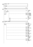
4.相对坐标
W5.02 MOVL
(498)
[OP1] [OP2]
D100 D24
分层预压设定 压制高度低位 伺服定位-脉冲 输出设定量低 位
<cD00024>
c46
000010 (000040) W5.02 20.10 PLS2
(887)
#0 #0010 D20 D26
[OP1] [OP2] [OP3]
[OP1] [OP2] [OP3] <cD00015>
c17 c20 <15.02> a32
SET 15.02 000008 (000032) 15.02 14.10 SPED
(885)
伺服下降 按钮
I:1.01
#0 #0010 #0
[OP1] [OP2] [OP3]
<15.02> a32
RSET 15.02 000009 (000038)
伺服定位-加速 比率
<cD00020>
c10 c50
[OP4]
伺服定位-启动 频率低位
<cD00026>
c14 c50
A280.03 20.10
<20.10> b41
000011 (000045)
5.绝对坐标(相对于原点坐标的位置)
W1.03 MOV
(021)
D102 D24
[OP1] [OP2]
伺服定位-脉冲 输出设定量低 位
伺服定位-启动 频率低位
<cD00026>
c42 c50
MOV
(021)
#0 D27
[OP1] [OP2]
伺服定位-启动 频率高位
arduino uno r3 控制工业伺服电机程序
} }
if (d2==1)//中断后进入此程序,也就是碰到零点开关后。 {
delay(dy); digitalWrite(0,LOW); digitalWrite(1,HIGH); digitalWrite(DIR_1,HIGH);
while (d0>0) {
digitalWrite(PUL_1,HIGH); delayMicroseconds(t1); digitalWrite(PUL_1,LOW); delayMicroseconds(t1); d0--; } delay(dy); digitalWrite(1,LOW); digitalWrite(0,HIGH); digitalWrite(DIR_1,LOW); while (d1>0) { digitalWrite(PUL_1,HIGH); delayMicroseconds(t1); digitalWrite(PUL_1,LOW); delayMicroseconds(t1); d1--; } d0=30000;//数值重装 d1=30000; //数值重装 } }
void loop() {
if (d2==0) { delay(dy); digitalWrite(DIR_1,LOW); while (d2==0)
Arduino教程(提高篇)——舵机的驱动
Arduino教程(提高篇)——舵机的驱动在机器人机电控制系统中,舵机控制效果是性能的重要影响因素。
舵机可以在微机电系统和航模中作为基本的输出执行机构,其简单的控制和输出使得单片机系统非常容易与之接口。
舵机是一种位置(角度)伺服的驱动器,适用于那些需要角度不断变化并可以保持的控制系统。
目前在高档遥控玩具,如航模,包括飞机模型,潜艇模型;遥控机器人中已经使用得比较普遍。
舵机是一种俗称,其实是一种伺服马达。
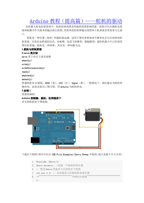
1.舵机与控制原理2.servo类介绍servo类下有以下成员函数attach()//write()//writeMicroseconds()//read()//attached()//detach()//普通舵机有3根线:GND(黑)、VCC(红)、Signal(黄),一般情况下,我们建议为舵机单独供电,此处实验为了图方便,用arduino为舵机供电。
3.实例1需要的器材:arduino控制器、舵机、杜邦线若干首先将舵机如下图连接:下载以下例程(程序可以在IDE>File>Examples>Servo>Sweep中找到,我只是做个中文介绍)1.#include <Servo.h>2.Servo myservo; //创建一个舵机控制对象3.// 使用Servo类最多可以控制8个舵机4.intpos = 0; // 该变量用与存储舵机角度位置5./*~~~~~~~~~~~~~~~~~~~~~~~~~~华丽的分割线~~~~~~~~~~~~~~~~~~~~~~~~~~*/6.void setup()7.{8.myservo.attach(9); // 该舵机由arduino第九脚控制9.}10./*~~~~~~~~~~~~~~~~~~~~~~~~~~华丽的分割线 ~~~~~~~~~~~~~~~~~~~~~~~~~~*/11.void loop()12.{13.for(pos = 0; pos< 180; pos += 1) // 从0度到180度运动14.{ // 每次步进一度15.myservo.write(pos); // 指定舵机转向的角度16.delay(15); // 等待15ms让舵机到达指定位置17.}18.for(pos = 180; pos>=1; pos-=1) //从180度到0度运动19.{20.myservo.write(pos); // 指定舵机转向的角度21.delay(15); // 等待15ms让舵机到达指定位置22.}23.}24.4.实例2需要的器材:arduino控制器、舵机、电位器、杜邦线若干首先将舵机如下图连接:下载以下例程(程序可以在IDE>File>Examples>Servo>Knob中找到)1.#include <Servo.h>2.3.Servo myservo;4.//创建一个舵机控制对象5.6.intpotpin = 0; //该变量用于存储用电位器读出的模拟值7.intval;8.// 该变量用与存储舵机角度位置9.10.void setup()11.{12.myservo.attach(9);13.// 该舵机由arduino第九脚控制14.}15.16.void loop()17.{18.val = analogRead(potpin); //读取电位器控制的模拟值 (范围在0-1023)19.val = map(val, 0, 1023, 0, 179); // scale it to use it with the servo(value between 0 and 180)20.myservo.write(val);21.// 指定舵机转向的角度22.delay(15);23.// 等待15ms让舵机到达指定位置24.}5.其他驱动方法:传送门:。
- 1、下载文档前请自行甄别文档内容的完整性,平台不提供额外的编辑、内容补充、找答案等附加服务。
- 2、"仅部分预览"的文档,不可在线预览部分如存在完整性等问题,可反馈申请退款(可完整预览的文档不适用该条件!)。
- 3、如文档侵犯您的权益,请联系客服反馈,我们会尽快为您处理(人工客服工作时间:9:00-18:30)。
if (d2==1)//中断后进入此程序,也就是碰到零点开关后。 {
delay(dy); digitalWrite(0,LOW); digitalWrite(1,HIGH); digitalWrite(DIR_1,HIGH);
while (d0>0) {
digitalWrite(PUL_1,HIGH); delayMicroseconds(t1); digitalWrite(PUL_1,LOW); delayMicroseconds(t1); d0--; } delay(dy); digitalWrite(1,LOW); digitalWrite(0,HIGH); digitalWrite(DIR_1,LOW); while (d1>0) { digitalWrite(PUL_1,HIGH); delayMicroseconds(t1); digitalWrite(PUL_1,LOW); delayMicroseconds(t1); d1--; } d0=30000;//数值重装 d1=30000; //数值重装 } }
digitalWrite(0,HIGH); digitalWrite(1,HIGH); pinMode(DIR_1,OUTPUT); pinMode(PUL_1,OUTPUT); pinMode(0,OUTPUT);//正反转指示灯 pinMode(1,OUTPUT); //正反转指示灯 attachInterrupt(0, blink,RISING);//中断函数 }
arduino uno r3 控制工业伺服电机程序 一. 本案例实现功能说明:
arduino r3 通电后伺服电机慢速反转(寻找归零开关),碰到 U 型光 电开关(归零开关)后高速正转,设定的正转脉冲数发送完成后,电 机反转,设定的反转脉冲数发送完成后,跳转到正转,如此循环下去。 二. 案例图片:
不好意思,图片拍得比较黑函数 {
d2=1; }
版权:nokiagx@ 梁先生
void loop() {
if (d2==0) { delay(dy); digitalWrite(DIR_1,LOW); while (d2==0)
{ digitalWrite(PUL_1,HIGH); delayMicroseconds(t0); digitalWrite(PUL_1,LOW); delayMicroseconds(t0);
零点开关接 arduino uno r3 的 2 脚,不是直接接的,用光隅 PC817C 隔离,零点开关用 24V 电压,来自伺服驱动器,脉冲输出 7 脚,方向 输出 6 脚。
脉冲输出和方向输出也是用光隅 PC817C 隔离传送到伺服驱动器的 PUL 和 DIR 接点上,不说这么多,你们懂的了。 另外,伺服驱动器接两个正向极限和反向极限开关。 注意:三个光电开关为常闭型。 四.上程序:
int PUL_1=7; int DIR_1=6; unsigned long d0=30000; //d0 为正向脉冲个数 unsigned long d1=30000; //d1 为反向脉冲个数 unsigned int d2=0; // unsigned int t0=200;//寻找零点开关速度 unsigned int t1=100; //正反转速度 unsigned int dy=500; void setup( ) {
