rfc1370.Applicability Statement for OSPF
中国联通本地综合承载与传送设备技术规范

中国联通本地综合承载与传送设备技术规范12中国联通公司发布中国联通本地综合承载传送网设备技术规范v1.0Technical Specification for China Unicom Local Unified Transport Network Equipment v1.0(NEQ)中国联通公司企业标准QB/CU 057- -1-18发布-1-18实施目次1范围............................................................................................ 错误!未定义书签。
2规范性引用文件 ....................................................................... 错误!未定义书签。
3定义、术语和缩略语 ............................................................... 错误!未定义书签。
4设备基本要求............................................................................ 错误!未定义书签。
4.1 设备基本要求..................................................................... 错误!未定义书签。
5通用技术规范............................................................................ 错误!未定义书签。
5.1 设备系统架构..................................................................... 错误!未定义书签。
一般的Internet电话的组网图
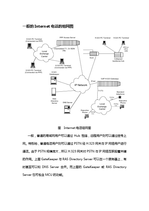
一般的Internet电话的组网图PPP Access Server H.323 PC Terminal H.323 PC Terminal图 Internet电话组网图一般,普通的局域网用户可以通过Hub相连,远程用户则可以通过拨号上网。
特别地,普通电话用户则可以通过PSTN经H.323网关与IP网络用户进行通话。
由于PSTN规模庞大,所以H.323网关对PSTN与IP网络互联起着关键的作用。
上图GateKeeper与RAS Directory Server可以在一个服务器上,有时甚至可以和DNS Server合并。
而上图的GateKeeper或RAS Directory Server也可包含MCU的功能。
3、传输协议在IETF的MMUSIC工作组的草案《The Internet Multimedia Conference Architecture》中定义的视讯会议的协议栈如下:|<--- Conference Management --->|<--- Media Agents --->|| | || Conference | Conference | Audio/ | Shared || Setup & Discovery | Course Control | Video | Applications |+-------------------------+------+--------+-+--------+------------+ +| S D P | | Distr. | RTP / | Reliable | || SAP | SIP | HTTP | SMTP | RSVP | Ctrl(1)| RTCP |Multicast(2)| |+-----+--+--+------+------+ +--+--------+----------+------------+--+| UDP | T C P | | U D P |+--------+----------------+---+--------------------------------------+| IP + IP Multicast |+--------------------------------------------------------------------+| Integrated Services Forwarding |+--------------------------------------------------------------------+ 图 Internet Multimedia Conferencing protocol stacks一般说来,呼叫建立和控制大多建立在TCP(面向连接)基础上,而音频流的传送则建立在UDP(面向无连接)基础上,为保证传送的实时性,IETF增加了几个重要的协议:1) RSVP:(Resource Reservation Protocol)一般说来,在IP网络上保留足够的带宽用于多媒体的传送是十分困难的,为此IETF定义了资源预留协议(RSVP)。
非常好的传输层SCTP协议教程
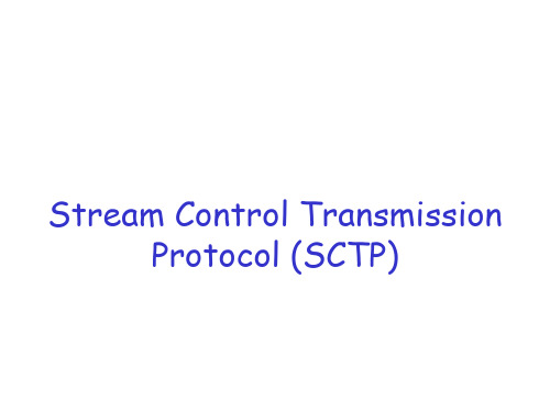
Gap ACK blk #1 start TSN offset Gap ACK blk #1 end TSN offset ........
Gap ACK blk #N start TSN offset Gap ACK blk #N end TSN offset Duplicate TSN 1 …….. Duplicate TSN X
Description
* 1 0 (Begin) First Piece of fragmented message * 0 0 Middle piece of fragmented message * 0 1 (End) Last piece of fragmented message * 1 1 Non-fragmented message
Offset is relative to cumulative TSN.
GAP ACK blocks are blocks received after cum TSN.
Chunk Bundling in SCTP
SCTP PDU
Source Port Destination Port Verification Tag Checksum Chunk 1
(Transport Services Working Group) Sophia Antipolis
6/00 12 10/00 22
4/01 19
– IETF recognizes broader scope San Jose (Connectathon) 2/02 6
– Proposed Standard - RFC2960 U. of Essen (Germany)
multistreaming instead of one ordered stream, up to 64K independent ordered streams
Cp-CPS

Summary
These two I-Ds are intended to become informational RFCs in support of the SIDR work Additional CPS Templates for CAs at other points in the resource allocation hierarchy may be needed Comments are welcome!
There is one outline in 3647; it nominally applies to both CP and CPS documents
What is a CP?
X.509 defines a certificate policy as
"a named set of rules that indicates the applicability of certificate to a particular community and/or class applications with common security requirements"
What is a CPS?
A CPS is defined by RFC 3647 as
“a more detailed description of the practices followed by a CA in issuing and otherwise managing certificates […] published by or referenced by the CA”
id-cp-ipAddr-asNumber OBJECT IDENTIFIER ::= { iso(1) identified-organization(3) dod(6) internet(1) security(5) mechanisms(5) pkix(7) cp(14) 2 }
云计算数据中心网络虚拟化技术
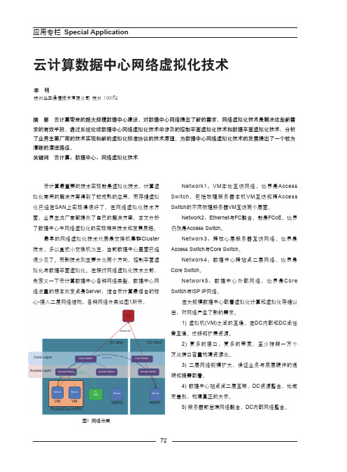
云计算数据中心网络虚拟化技术Network1:VM 本地互访网络,边界是Access Switch ,包括物理服务器本机VM 互访和跨Access Switch 的不同物理服务器VM 互访两个层面。
Network2:Ethernet 与FC 融合,就是FCoE ,边界仍然是Access Switch 。
Network3:跨核心层服务器互访网络,边界是Access Switch 与Core Switch 。
Network4:数据中心跨站点二层网络,边界是Core Switch 。
Network5:数据中心外部网络,边界是Core Switch 与ISP IP 网络。
在大规模数据中心部署虚拟化计算和虚拟化存储以后,对网络产生了新的需求。
1) 虚拟机(VM)之间的互通,在DC 内部和DC 间任意互通、迁移和扩展资源。
2) 更多的接口,更多的带宽,至少按照一万个万兆端口容量构建资源池。
3) 二层网络规模扩大,保证业务与底层硬件的透明和随需部署。
4) 数据中心站点间二层互联,DC 资源整合,地域无差别,构建真正的大云。
5) 服务器前后端网络融合,DC 内部网络整合。
李 明杭州华三通信技术有限公司 杭州 100052摘 要 云计算带来的超大规模数据中心建设,对数据中心网络提出了新的需求,网络虚拟化技术是解决这些新需求的有效手段,通过系统论述数据中心网络虚拟化技术中涉及的控制平面虚拟化技术和数据平面虚拟化技术,分析了业界主要厂商的技术实现和新的虚拟化标准协议的技术原理,为数据中心网络虚拟化技术的发展提出了一个较为清晰的演进路径。
关键词 云计算;数据中心;网络虚拟化技术云计算最重要的技术实现就是虚拟化技术,计算虚拟化商用的解决方案得到了较成熟的应用,而存储虚拟化已经在SAN 上实现得很好了,在网络虚拟化技术方面,业界主流厂商都提出了自己的解决方案,本文分析了数据中心中网络虚拟化的实现相关技术和发展思路。
最早的网络虚拟化技术代表是交换机集群Cluster 技术,多以盒式小交换机为主,当前数据中心里面已经很少见了。
SMTP协议RFC文档中文版

RFC821 简单邮件传输协议(SMTP)(RFC821 SIMPLE MAIL TRANSFER PROTOCOL)目录1. 介绍 22. SMTP模型 33. SMTP过程 43.1. MAIL 43.2. 转发 53.3. 确认和扩展 63.4. 发送信件(mailing)和获得信件(sending) 7 3.5. 打开和关闭73.6. 转发 83.7. 域93.8. 改变角色94. SMTP说明94.1. SMTP命令94.1.1. 命令语法94.1.2. COMMAND语法格式134.2. SMTP响应154.3. 命令和应答序列164.4. 状态图174.5. 详细内容184.5.1. 最小实现184.5.2. 透明性194.5.3. 大小19附录 A TCP传输服务19附录 B NCP传输服务20附录 C NITS 20附录 D X.25传输服务 20附录 E 应答码构成方法20附录 F 一些例子22参考资料361. 介绍简单邮件传输协议(SMTP)的目标是可靠高效地传送邮件,它独立于传送子系统而且仅要求一条可以保证传送数据单元顺序的通道。
附录A,B,C和D描述了不同传送服务下SMTP的使用。
在名词表中还定义了本文档中使用的术语。
SMTP的一个重要特点是它能够在传送中接力传送邮件,传送服务提供了进程间通信环境(IPCE),此环境可以包括一个网络,几个网络或一个网络的子网。
理解到传送系统(或IPCE)不是一对一的是很重要的。
进程可能直接和其它进程通过已知的IPCE通信。
邮件是一个应用程序或进程间通信。
邮件可以通过连接在不同IPCE上的进程跨网络进行邮件传送。
更特别的是,邮件可以通过不同网络上的主机接力式传送。
2. SMTP模型SMTP设计基于以下通信模型:针对用户的邮件请求,发送SMTP建立与接收SMTP之间建立一个双向传送通道。
接收SMTP可以是最终接收者也可以是中间传送者。
SMTP命令由发送SMTP发出,由接收SMTP接收,而应答则反方面传送。
rfc1721.RIP Version 2 Protocol Analysis

Network Working Group G. Malkin Request for Comments: 1721 Xylogics, Inc. Obsoletes: 1387 November 1994 Category: InformationalRIP Version 2 Protocol AnalysisStatus of this MemoThis memo provides information for the Internet community. This memo does not specify an Internet standard of any kind. Distribution ofthis memo is unlimited.AbstractAs required by Routing Protocol Criteria (RFC 1264), this reportdocuments the key features of the RIP-2 protocol and the currentimplementation experience. This report is a prerequisite toadvancing RIP-2 on the standards track.AcknowledgementsThe RIP-2 protocol owes much to those who participated in the RIP-2working group. A special thanks goes to Fred Baker, for his help on the MIB, and to Jeffrey Honig, for all his comments.1. Protocol DocumentsThe RIP-2 applicability statement is defined in RFC 1722 [1].The RIP-2 protocol description is defined in RFC 1723 [2]. This memo obsoletes RFC 1388, which specifies an update to the "RoutingInformation Protocol" RFC 1058 (STD 34).The RIP-2 MIB description is defined in RFC 1724 [3]. This memoobsoletes RFC 1389.2. Key FeaturesWhile RIP-2 shares the same basic algorithms as RIP-1, it supportsseveral new features. They are: external route tags, subnet masks,next hop addresses, and authentication.The significant change from RFC 1388 is the removal of the domainfield. There was no clear agreement as to how the field would beused, so it was determined to leave the field reserved for futureexpansion.Malkin [Page 1]2.1 External Route TagsThe route tag field may be used to propagate information acquiredfrom an EGP. The definition of the contents of this field are beyond the scope of this protocol. However, it may be used, for example, to propagate an EGP AS number.2.2 Subnet MasksInclusion of subnet masks was the original intent of opening the RIP protocol for improvement. Subnet mask information makes RIP moreuseful in a variety of environments and allows the use of variablesubnet masks on the network. Subnet masks are also necessary forimplementation of "classless" addressing, as the CIDR work proposes.2.3 Next Hop AddressesSupport for next hop addresses allows for optimization of routes inan environment which uses multiple routing protocols. For example,if RIP-2 were being run on a network along with another IGP, and one router ran both protocols, then that router could indicate to theother RIP-2 routers that a better next hop than itself exists for agiven destination.2.4 AuthenticationOne significant improvement RIP-2 offers over RIP-1, is the addition of an authentication mechanism. Essentially, it is the sameextensible mechanism provided by OSPF. Currently, only a plain-text password is defined for authentication. However, more sophisticated authentication schemes can easily be incorporated as they aredefined.2.5 MulticastingRIP-2 packets may be multicast instead of being broadcast. The useof an IP multicast address reduces the load on hosts which do notsupport routing protocols. It also allows RIP-2 routers to shareinformation which RIP-1 routers cannot hear. This is useful since a RIP-1 router may misinterpret route information because it cannotapply the supplied subnet mask.3. RIP-2 MIBThe MIB for RIP-2 allows for monitoring and control of RIP’soperation within the router. In addition to global and per-interface counters and controls, there are per-peer counters which provide the status of RIP-2 "neighbors".Malkin [Page 2]The MIB was modified to deprecate the domain, which was removed from the protocol. It has also been converted into version 2 format.4. ImplementationsCurrently, there are three complete implementations of RIP-2: GATED, written by Jeffrey Honig at Cornell University; Xylogics’s AnnexCommunication server; and an implementation for NOS, written by Jeff White. The GATED implementation is available by anonymous FTP from as pub/gated/gated-alpha.tar.Z. The implementation for NOS is available by anonymous FTP from as/hamradio/packet/tcpip/incoming/rip2.zip.Additionally, Midnight Networks has produced a test suite whichverifies an implementation’s conformance to RFC 1388 implemented over RFC 1058.The author has conducted interoperability testing between the GATEDand Xylogics implementations and found no incompatibilities. Thistesting includes verification of protection provided by theauthentication mechanism described in section 2.4.5. Operational experienceXylogics has been running RIP-2 on its production systems for fivemonths. The topology includes seven subnets in a class B address and various, unregistered class C addresses used for dial-up access. Six systems, in conjunction with three routers from other vendors anddozens of host systems, operate on those subnets.The only problem which has appeared is the reaction of some routersto Version 2 RIP packets. Contrary to RFC 1058, these routersdiscard Version 2 packets rather than ignoring the fields not defined for Version 1.6. References[1] Malkin, G., "RIP Version 2 Protocol Applicability Statement", RFC 1722, Xylogics, Inc., November 1994.[2] Malkin, G., "RIP Version 2 - Carrying Additional Information",RFC 1723, Xylogics, Inc., November 1994.[3] Malkin, G., and F. Baker, "RIP Version 2 MIB Extension", RFC1724, Xylogics, Inc., Cisco Systems, November 1994.Malkin [Page 3]7. Security ConsiderationsSecurity issues are discussed in sections 2.4 and 4.8. Author’s AddressGary Scott MalkinXylogics, Inc.53 Third AvenueBurlington, MA 01803Phone: (617) 272-8140EMail: gmalkin@Malkin [Page 4]。
宽带网络技术第5章 MPLS技术

第5章 MPLS技术
Label POP:Label POP是标签转发的基本动作之一, 是组成标签转发信息表的一部分。作用:在于将一个 MPLS报文去除标签,以下一层协议转发。POP动作一 般用于MPLS域的边缘设备,当MPLS报文出MPLS域, 进入IP转发域时,需要将标签弹出。 数据流(Stream):沿着同一路径、属于同一FEC的一 组包被视为一个数据流。数据流通常是一个或多个业务 流的集合。在不支持流合并(Stream Merge)的网络 中,一个数据流也将对应一个标签。 业务流(Flow):一个应用到应用的数据流称为业务 流。早期的IP Switching技术就是根据业务流决定转发 的路由。很显然,业务流的数量远远大于数据流数量, 因而其网络扩展性大大低于基于数据流的技术。
MPLS不被限制于任何特殊的链路层协议,利用节点 现有的路由机制决定转发路径,它本身包含一系列简单 的核心机制。 (1)对一个流指定标签的语义。将一个标签与一个特殊 的数据流相关联。 (2)转发方法。通过定长的短标签来简化转发,转发时 仅需要简单的功能,如标签查找、标签替换以及对TTL (分组传输生命期)值的操作,在某些情况下,还可以 直接使用第二层交换技术实现快速转发。 (3)标签分配方法。允许节点决定为特定的流分配某一 种标签,可以使用一些专门的控制协议,或附在路由协 议上来完成标签分配。
第5章 MPLS技术
2.MPLS组件 从基础架构的角度来看,MPLS将传统的路由选 择机制划分为控制平面和数据平面。 控制平面一一负责处理相邻设备的路由选择和标签 信息的交换。 数据平面一一根据目的地址或标签转发流量(也称 为转发平面)。
第5章 MPLS技术
5.2.2 MPLS工作原理
H3C S5500-EI RIP配置(实例)
目录1 RIP配置................................................................................................................................................ 1-11.1 简介 .................................................................................................................................................. 1-11.1.1 RIP工作机制 .......................................................................................................................... 1-11.1.2 RIP的启动和运行过程............................................................................................................ 1-21.1.3 RIP的版本.............................................................................................................................. 1-31.1.4 RIP的报文格式....................................................................................................................... 1-31.1.5 支持的RIP特性..................................................................................................................... 1-51.1.6 协议规范 ................................................................................................................................ 1-51.2 配置RIP的基本功能 ........................................................................................................................ 1-51.2.1 配置准备 ................................................................................................................................ 1-51.2.2 配置RIP的基本功能.............................................................................................................. 1-51.3 配置RIP路由特性............................................................................................................................ 1-71.3.1 配置接口附加度量值 .............................................................................................................. 1-71.3.2 配置RIP-2路由聚合.............................................................................................................. 1-81.3.3 禁止RIP接收主机路由.......................................................................................................... 1-91.3.4 配置RIP发布缺省路由.......................................................................................................... 1-91.3.5 配置RIP对接收/发布的路由进行过滤 ................................................................................. 1-101.3.6 配置RIP协议优先级............................................................................................................ 1-111.3.7 配置RIP引入外部路由........................................................................................................ 1-111.4 调整和优化RIP网络 ...................................................................................................................... 1-111.4.1 配置RIP定时器................................................................................................................... 1-111.4.2 配置水平分割和毒性逆转..................................................................................................... 1-121.4.3 配置最大等价路由条数......................................................................................................... 1-131.4.4 配置RIP-1报文的零域检查 ................................................................................................. 1-131.4.5 配置源地址检查.................................................................................................................... 1-131.4.6 配置RIP-2报文的认证方式 ................................................................................................. 1-141.4.7 配置RIP邻居....................................................................................................................... 1-141.4.8 配置RIP和MIB绑定........................................................................................................... 1-151.4.9 配置RIP报文的发送速率 .................................................................................................... 1-151.5 RIP显示和维护 ............................................................................................................................... 1-151.6 RIP典型配置举例............................................................................................................................ 1-161.6.1 配置RIP的版本................................................................................................................... 1-161.6.2 配置RIP引入外部路由........................................................................................................ 1-181.6.3 配置RIP接口附加度量值 .................................................................................................... 1-201.6.4 配置RIP发布聚合路由........................................................................................................ 1-221.7 常见配置错误举例........................................................................................................................... 1-241.7.1 收不到邻居的RIP更新报文................................................................................................. 1-241.7.2 RIP网络发生路由振荡.......................................................................................................... 1-241 RIP配置在以下路由协议的介绍中所指的路由器及路由器图标,代表了一般意义下的路由器以及运行了路由协议的三层交换机。
Applicability of LiNbO3, Langasite and GaPO4
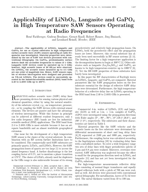
ieee transactions on ultrasonics,ferroelectrics,and frequency control,vol.51,no.11,november20041427 Applicability of LiNbO3,Langasite and GaPO4 in High Temperature SA W Sensors Operatingat Radio FrequenciesRen´e Fachberger,Gudrun Bruckner,Gernot Knoll,Robert Hauser,J¨o rg Biniasch,and Leonhard Reindl,Member,IEEEAbstract—The applicability of LiNbO3,langasite and GaPO4for use as crystal substrates in high temperature surface acoustic wave(SA W)sensors operating at radio fre-quencies was investigated.Material properties were deter-mined by the use of SA W test devices processed with con-ventional lithography.On GaPO4,predominantly surface defects limit the accessible frequencies to values of1GHz. Langasite SA W devices could be operated up to3GHz; however,high acoustic losses of20dB/s were observed. On LiNbO3,the acoustic losses measured up to3.5GHz are one order of magnitude less.Hence,SA W sensors capa-ble of wireless interrogation were designed and processed on YZ-cut LiNbO3.The devices could be successfully op-erated in the industrial-scientific-medical(ISM)band from2.40to2.4835GHz up to400 C.I.IntroductionR eflective surface acoustic wave(SAW)delay lines are promising devices for sensing various physical and chemical quantities,either by using the natural sensitiv-ity of the substrate crystal,e.g.,on temperature,pressure, etc.,or by coupling the SAW devices with external sensor elements.The devices are passive and have the advantage of wireless interrogation.While this feature in principle can be achieved at different readout frequencies,only a few radio frequency(RF)bands are free for industrial-scientific-medical(ISM)applications.The ISM band from 2.4to2.4835GHz is most suitable because it has an ad-equate bandwidth and an almost worldwide geographical extension.One issue for the development of a high temperature SAW sensor is the choice of the crystal substrate.In com-bination with an RF system further limitations have to be considered.The commercially used SAW substrates are primarily quartz,LiTaO3,and LiNbO3.However,the SAW propagation losses of quartz are too large[1]to access the aimed frequency band.A further disadvantage is the low coupling factor of0.1%,not to mention a phase transition at573◦C.The choice of LiTaO3already used for duplexers in the GHz range is also unfavorable because of its strongManuscript received February11,2004;accepted July1,2004. R.Fachberger,G.Bruckner,G.Knoll,and R.Hauser are with Carinthian Tech Research,Europastrasse4/1,A-9524Villach,Aus-tria(e-mail:rene.fachberger@ctr.at).J.Biniasch and L.Reindl are with the Institut of Microsystem Technology,Albert-Ludwig University,Georges-Koehler Allee103, D-79110Freiburg,Germany.pyroelectricity and relatively high propagation losses.On LiNbO3both the pyroelectric effect and the propagation losses are lower.Moreover,this crystal substrate has al-ready been used successfully in RF sensor systems[2]–[4]. The limiting factor for a high temperature application is the decomposition known to begin at300◦C[5].Other sub-strates such as langasite(La3Ga5SiO14)and GaPO4are known to be high temperature-resistive up to1000◦C[6], [7].Yet the RF-SAW properties of these substrates have barely been investigated.In this paper the RF characteristics of Rayleigh waves on LiNbO3,langasite,and GaPO4are compared.Material parameters like the SAW propagation losses on the free substrate essential for the design of reflective SAW delay lines were determined.Furthermore,the high temperature behavior of a reflective delay line on LiNbO3operating in the ISM band from2.40to2.4835GHz is presented.II.ExperimentalCommercial4-in.wafers of LiNbO3(LN)and langa-site(LGS)as well as1-in.×1-in.samples of GaPO4 (GPO)were investigated using the propagation directions with Euler angles(0◦,−90◦,−90◦),(0◦,138.5◦,26.6◦),and (90◦,5◦,0◦),respectively.The substrates and their charac-teristics are listed in Table I.Material properties like the SAW velocity and the acoustic losses on the free substrate were determined by differential measurements of short and long delay lines [8],[9]separated at2500µm and5000µm,respectively. Furthermore,the coupling factor was calculated according to the Ingebrigtsen relation[10]by evaluating delay lines with a metallized surface.To cover a wide frequency range two sets of delay lines withfinger periodicities(pitch)of 2µm and0.8µm were realized.Moreover,overtones were excited.SAW diffraction was neglected because the effect is small for the propagation direction used on LiNbO3and langasite[11]and has not yet been investigated for the GaPO4substrate.For high-temperature measurements reflective delay lines consisting of normalfinger transducers and equally shaped reflectors both with a pitch of700nm were real-ized as well.All devices were processed with conventional optical lithography.For metallization,layers of Ti/Al were used.The metal thickness varied from50to100nm.0885–3010/$20.00c 2004IEEE1428ieee transactions on ultrasonics,ferroelectrics,and frequency control,vol.51,no.11,november2004TABLE IInvestigated Rayleigh W ave Substrates.Common Samplecrystal cut Euler angles diameterMaterial designation(λ,µ,θ)(in.)LimitationsLN Y-Z cut(0◦,−90◦,−90◦)4Decomposition atLiNbO3temperatures>300◦CLGS48.5◦rot Y(0◦,138.5◦,26.6◦)4RF properties barelyLa3Ga5SiO14investigatedGPO Y-boule5◦(90◦,5◦,0◦)ca.1RF properties barelyGaPO4investigatedMeasurements at room temperature were performed on a wafer prober.For measurements at elevated tempera-tures the SAW devices were mounted in ceramic housings and heated in an oven equipped with a ceramic tube.Air was chosen as the surrounding atmosphere.Coaxial cables resistive to temperatures of up to600◦C were used for sig-nal transmission.All measurements were carried out with a network analyzer(NWA).The delay lines on LiNbO3were operated up to frequen-cies of3.5GHz.The signal attenuation varied from30to 40dB.On langasite,due to the lower SAW velocity and coupling factor,slightly lower frequencies of3GHz are ac-cessible and higher values of the signal attenuation from55 to70dB were observed.On GaPO4submicrometer struc-tures could not be realized.This is basically a consequence of scratches and a relative large curvature of the investi-gated samples.Despite an additional polishing process the quality of the crystal surface could not be improved.Thus on GaPO4the accessible frequencies were limited to about 1GHz,with the signal attenuation varied between65and 80dB.III.Measurements of Material PropertiesThe determined values of the SAW velocity and the coupling factor of the investigated substrates are listed in Table II and compared to values from the literature.For LiNbO3good agreement for both values was achieved.In the case of langasite the measured value of the coupling factor of0.44%is a bit higher than the published value of 0.34%.In the case of GaPO4only the value of the SAW velocity on the free surface could be determined,because the signal of the delay lines with a metallized surface was too weak for evaluation.The measured values of the acoustic losses on the free substrate over frequency are shown in Fig.1.Except for GaPO4each point refers to a mean value of at least ten different measurements.The results are in excellent agree-ment with theory,α=α1f+α2f2,(1) predicting a quadratic dependence of the acoustic lossesαin dB with frequency f due to viscous damping[1].For Fig. 1.SA W propagation losses on free LiNbO3,Langasite,and GaPO4over frequency.radio frequencies the linear term due to air loading can be neglected.Quadraticfits according to(1)are illustrated as continuous lines in Fig.1;the corresponding values of the coefficientα2are listed in Table III.For LiNbO3the determined value of0.65forα2is somewhat lower com-pared to the literature where a value of0.88is published [1].Consequently,the value of the propagation losses of 3.9dB/µs at2.45GHz is relatively low.On langasite and GaPO4the observed acoustic damping is about one or-der of magnitude higher.For a comparison at2.45GHz, values of17dB/µs and29dB/µs,respectively,are de-termined.Deviations from the quadratic dependence on frequency observed on langasite may indicate that despite theory SAW diffraction occurs,especially on the long delay lines.IV.High Temperature Measurements Fig.2shows the time response of a SAW reflective delay line on LN YZ at room temperature operating at2.45GHz measured via a NWA.Three pulses with time delaysτ1,τ2,andτ3of0.65µs,1.30µs,and1.95µs,respectively,arefachberger et al.:linbo 3,langasite,and gapo 4in high temperature saw sensors1429TABLE IIMeasured V alues of the SA W Velocity and the Coupling F actor Versus V alues of the Literature.Measured values Published values Substrate Coupling SA W Coupling SA W crystalfactor k 2velocity factor k 2velocity Reference (%)(m/s)(%)(m/s)LN YZ4.353492 4.503488[12]LGS 48.5◦rot Y 0.4427400.342743[11]GPO 5◦rot Z—2501ca.0.30ca.2500[6]TABLE IIISA W Propagation Losses on Free LiNbO 3,Langasite,andGaPO 4.Substrate Acoustic losses α2·f 2Acoustic lossescrystal(in dB/µs,f in GHz)(in dB/µs at 2.45GHz)LN YZ0.65f 2 3.9LGS 48.5◦rot Y 2.8f 217GPO 5◦rot Z4.9f 229Fig.2.Time response of a reflective SA W delay line on LN YZ op-erating at 2.45GHz.visible.The signal-to-noise ratio (SNR)of the pulses varies from 45to 30dB.The first and the third peaks refer to single reflections of the SAW at the metallization gratings.The second peak refers to a double reflection of the first reflector and the transducer.Similar devices were heated to a temperature of 370◦C.The sensitivity of the device on temperature can be ex-pressed by a quadratic Taylor series∆τi τi=T CD 1(T −T Ref )+T CD 2(T −T Ref )2,(2)∆τi indicating the change of the time delay τi of the i -th pulse with a change of temperature T relative to a ref-erence temperature T Ref .TCD 1and TCD 2,respectively,represent the linear and the quadratic temperaturecoef-Fig.3.Temperature over time measured with a reflective SA W delay line and with a PT 100resistor (reference).ficients of delay.Hence,by evaluating the time delay of the pulses τi a temperature value T can be estimated as-suming that TCD 1,TCD 2,and T Ref are predetermined.The values of τi were determined utilizing a numeric peak finder in combination with a quadratic interpolation.The resolution of the time axis of the time response ∆t is in-versely proportional to the bandwidth (BW)of the RF measurement,∆t =1BW.(3)Provided a sufficient SNR of the pulses,the accuracy of the time estimation can be enhanced superficially by in-creasing the BW by adding zeros to the measured data.To compensate for perturbations of the measurement sys-tem,e.g.,the time delay due to the transmission line,a differential delay∆τ3,1=∆τ3−∆τ1τ3−τ1(4)of the third and the first peaks was evaluated.Results of this time evaluation method are presented in Fig.3.The calculated temperature values are compared with a temperature value measured via a ing a bandwidth of 400MHz a standard deviation σof 1.4◦C is observed over the whole measurement range.1430ieee transactions on ultrasonics,ferroelectrics,and frequency control,vol.51,no.11,november2004Fig.4.Signal attenuation over temperature of the time pulses of a reflective SA W delay line operating at2.45GHz.With a reduced bandwidth of83.5MHz attuned to the ISM band the device can be evaluated up to about300◦C with a standard deviation of8.8◦C.In both cases the same values for the TCD1,TCD2and T ref were used,printed in the top left corner of Fig.3.With the reduced bandwidth the measurement error in-creases drastically.Above300◦C the pulses are no longer detectable because of a strong increase of the signal atten-uation.This is visible in Fig.4,showing the signal atten-uation of the time pulses over temperature related to the values at room temperature.The peak values decrease by a value of up to20dB at elevated temperatures depending on the pulse position.This leads to a significant reduc-tion of the SNR,especially of the third pulse,impeding accurate peak detection.The discontinuity of the acoustic losses observed at150◦C can be referred to as an artifact of the sample holder with respect to the transmission line.V.DiscussionThe LiNbO3devices worked up to about400◦C at least for several hours.At this temperature the long-term dura-bility of the devices is mainly determined by the decompo-sition of the crystal substrate,leaving beside effects in the metallization.Recently the economic lifetime of LiNbO3 has been predicted to be in the region between10to50 days at400◦C[13].As the decomposition process follows the Arrhenius law the long-time durability at350◦C can be estimated to be already in the region of several years.Besides the decomposition of the crystal substrate,a limiting factor is the drastic increase of the signal attenu-ation of the time pulses with temperature.As the effect is correlated with the value of the time delay,it is probably due to a significant increase of the acoustic propagation attenuation with temperature.Relating the signal attenu-ation of the distinct time pulses,the acoustic propagation losses can be estimated to a value of about7.0dB/µs in the measured temperature range from20to370◦C.This would refer to a value of0.02dB/µs◦C.For the development of a high temperature resistant sensor,the reflective SAW delay line has to be optimized. The increasing SAW propagation losses with temperature can be compensated by weighting the signal strength of the time pulses,e.g.,varying the number offingers of the reflection gratings.At lower temperatures pulses with a higher time delay should have a higher intensity,thereby improving the SNR and the accuracy of the peak detection at elevated temperatures.An additional way to enhance the accuracy of the peak detection is applying another al-gorithm,e.g.,a phase evaluation,by which an accuracy of±0.2◦C has been estimated for a temperature measure-ment[14].VI.ConclusionsThe applicability of LiNbO3,langasite,and GaPO4as crystal substrates in high temperature SAW sensors oper-ating at radio frequencies was investigated.The surface quality was found to limit the accessible frequencies of SAWs on GaPO4to1GHz.The observed values of the propagation attenuation on GaPO4are significantly higher than those on langasite.However,it can be assumed that the values of the propagation attenuation might reduce together with an optimization of the crystal surface.Rayleigh waves with frequencies of up to3GHz can be excited on langasite by the use of overtones.Normalfinger transducers with a center frequency of2.45GHz referring to structure widths of ca.250nm on the investigated crys-tal cut are just within reach of conventional lithography. However,the high propagation attenuation of17dB/µs at 2.45GHz reduces the applicability of reflective delay lines on langasite for RF-SAW sensors.One possibility to over-come these difficulties would be the use of pseudo-SAWs like the shear horizontal wave,having the advantage of low acoustic damping.Reflective delay lines capable of wireless interrogation in the ISM band from2.4to2.4835GHz could be real-ized only on LiNbO3.These devices have been operated successfully up to400◦C.References[1] A.J.Slobodnik,Jr.,Materials and Their Influence on Perfor-mance in Acoustic Surface Waves. A.A.Oliver,Ed.Berlin, Heidelberg:Springer-Verlag,1978,p.251.[2]L.Reindl,G.Scholl,T.Ostertag,A.Pohl,and R.Weigel,“Wire-less remote identification and sensing with SA W devices,”in Proc.IEEE Int.Workshop on Commercial Radio Sensor and Communication Techniques,1998,pp.83–96.[3] C.S.Hartmann,“A global SA W ID tag with large data capac-ity,”in Proc.IEEE Ultrason.Symp.,2002,pp.63–67.[4]R.Peter and C.S.Hartmann,“Passive long range and hightemperature ID systems based on SA W technology,”in Proc.Sensor,Nuremberg,Germany,2003,pp.335–340.[5]L.O.Svaasand,M.Eriksrud,G.Nakken,and P.A.Grande,“Solid-solution range of LiNbO3,”J.Cryst.Growth,vol.22,p.230,1974.fachberger et al.:linbo 3,langasite,and gapo 4in high temperature saw sensors 1431[6]J.Hornsteiner,E.Born,and E.Riha,“Langasite for high tem-perature surface acoustic wave applications,”Phys.Stat.Sol.A ,vol.163,pp.R3–R4,1997.[7]P.Krempel,G.Schleinzer,and W.Walln¨o fer,“Gallium phos-phate,GaPO 4:A new piezoelectric crystal material for high-temperature sensorics,”Sens.Actuators ,vol.A61,pp.361–363,1997.[8]I.Schropp,“Modellierung akustischer Oberfl¨a chenwellenleit-er,”Master’s thesis,Lehrstuhl f¨u r Hochfrequenztechnik,Tech.Univ.Munich,Munich,Germany,1988.(in German)[9]I.Schropp,L.Reindl,H.P.Grassl,and R.Weigel,“Accurateprediction of dispersion and attenuation of long metal strip saw waveguides on anisotropic substrate,”in Proc.IEEE Ultrason.Symp.,1988,pp.263–267.[10]K. A.Ingebrigtsen,“Analysis of interdigital transducers,”inProc.IEEE Ultrason.Symp.,1972,p.403.[11]N.Naumenko and L.Solie,“Optimal cuts of langasite,La 3Ga 5SiO 14for SA W devices,”IEEE Trans.Ultrason.,Fer-roelect.,Freq.Contr.,vol.48,pp.530–537,2001.[12]C.K.Campbell,Surface Acoustic Wave Devices for Mobile andWireless Communications .Boston:Academic Press,Inc.,1998.[13]R.Hauser,L.Reindl,and J.Biniasch,“High-temperature sta-bility of LiNbO 3based SA W devices,”in Proc.IEEE Ultrason.Symp.,2003,pp.192–195.[14]L.Reindl,I.Shrena,H.Richter,and R.Peter,“High precisionwireless measurement of temperature by using surface acoustic waves sensors,”in Proc.Sensor ,Nuremberg,Germany,2003,pp.103–108.Ren´e Fachberger was born in Wels,Aus-tria,in 1971.He received the Diploma degree and the Ph.D.degree in physics from the Uni-versity of Technology in Vienna,Austria,in 1998and 2003,respectively.Working on his diploma thesis which was carried out in col-laboration with the Christian Doppler Lab-oratory,he earned experience in the field of material science.His Ph.D.work was funded by Siemens and Epcos AG in Munich,Ger-many,where he was introduced to the field of SA W applications.Since 2003he has been en-gaged in the development of SA W sensor systems at the CTR AG in Villach,Austria.He has authored or co-authored 12internationalpublications.Gudrun Bruckner received the Mag.and the Ph.D.degree in physics from the Univer-sity in Vienna in 1992and 1998,respectively.From 1996to 1999she worked on the design and setup of a new neutron detector facility at the ILL Grenoble,France.In 1999she joined CTR AG,Austria,where at first she worked in the field of MEMS.Since 2001she has been engaged in the development of SA W devices for sensor applications with research focus on SA W-design.She has authored or co-authored about 10publications,half of which are on SA Wdevices.Gernot Knoll received the academic degree of Dipl.-Ing.(FH)at the University of Applied Sciences in Industrial Electronics in Kapfen-berg,Austria,in 2002.His diploma thesis was written on the topic of Baluns for mo-bile applications in cooperation with EPCOS in Deutschlandsberg,Austria.From 2002to 2004he worked at CTR AG.His main field of activity was in high-frequency measurement and antenna design for passive SA W-sensor devices.He is currently employed as a scien-tific assistant in the Department of Aviationat the University of Applied Sciences in Graz,Austria.He is simul-taneously working on his doctoral degree inengineering.Robert Hauser received both his Diploma and his Ph.D.degree in physics from the Tech-nical University in Vienna,Austria,in 1989and 1995,respectively.Starting in 1990he did work on different facilities on high-field and high-pressure physics in Vienna,Austria;Grenoble,France;and Kumamoto,Japan.In 2001he joined CTR AG,Austria,where he is now engaged in the development of SA W-sensor devices operable at elevated tempera-tures.He has authored or co-authored about 80publications on selected topics in solidstate physics in journals and at international conferences.Since 2000he has been lecturer at the Technical University ofVienna.J¨o rg Biniasch was born in 1972in Essen,Germany.He received the Diplom-Ingenieur degree in engineering from the Clausthal University of Technology,Germany,in 2002.He is currently pursuing the Ph.D.degree at the Institute of Microsystem Technology of the Albert-Ludwigs-Universit¨a t Freiburg,Germany,involving the high-temperature be-havior of surface acousticdevices.Leonhard Reindl (M’93)received the Dipl.Phys.degree from the Technical University of Munich,Germany,in 1985and the Dr.Sc.Techn.degree from the University of Technol-ogy Vienna,Austria,in 1997.From 1985to 1999he was a member of the microacoustics group of the Siemens Corporate Technology department,Munich,Germany,where he was engaged in research and development on SA W convolvers,dispersive and tapped delay lines,ID-tags,and wireless passive SA W sensors.From 1999–2003he was university lecturer forcommunication and microwave techniques at the Institute of Electri-cal Information Technology,Clausthal University of Technology.In May 2003he accepted a full professor position at the laboratory for electrical instrumentation at the Institute for Microsystem Technol-ogy (IMTEK),Albert-Ludwigs-University of Freiburg,Germany.His research interests include wireless sensor and identifica-tion systems,surface acoustic wave devices and materials,and mi-crowave communication systems based on SA W devices.He holds 35patents on SA W devices and wireless passive sensor systems and has authored/co-authored approximately 130papers in this fields.He is member of the IEEE and of the Technical Program Committee of the IEEE Frequency Control Symposium.He is also engaged in technical committees of the German VDE/ITG Association.。
rfc6050.Session Initiation Protocol (SIP) Extension

Internet Engineering Task Force (IETF) K. Drage Request for Comments: 6050 Alcatel-Lucent Category: Informational November 2010 ISSN: 2070-1721A Session Initiation Protocol (SIP) Extensionfor the Identification of ServicesAbstractThis document describes private extensions to the Session Initiation Protocol (SIP) that enable a network of trusted SIP servers to assert the service of authenticated users. The use of these extensions isonly applicable inside an administrative domain with previouslyagreed-upon policies for generation, transport, and usage of suchinformation. This document does NOT offer a general serviceidentification model suitable for use between different trust domains or for use in the Internet at large.The document also defines a URN to identify both services and UserAgent (UA) applications. This URN can be used within the SIP header fields defined in this document to identify services, and also within the framework defined for caller preferences and callee capabilities to identify usage of both services and applications between end UAs.Status of This MemoThis document is not an Internet Standards Track specification; it is published for informational purposes.This document is a product of the Internet Engineering Task Force(IETF). It represents the consensus of the IETF community. It hasreceived public review and has been approved for publication by theInternet Engineering Steering Group (IESG). Not all documentsapproved by the IESG are a candidate for any level of InternetStandard; see Section 2 of RFC 5741.Information about the current status of this document, any errata,and how to provide feedback on it may be obtained at/info/rfc6050.Drage Informational [Page 1]Copyright NoticeCopyright (c) 2010 IETF Trust and the persons identified as thedocument authors. All rights reserved.This document is subject to BCP 78 and the IETF Trust’s LegalProvisions Relating to IETF Documents(/license-info) in effect on the date ofpublication of this document. Please review these documentscarefully, as they describe your rights and restrictions with respect to this document. Code Components extracted from this document must include Simplified BSD License text as described in Section 4.e ofthe Trust Legal Provisions and are provided without warranty asdescribed in the Simplified BSD License.Table of Contents1. Introduction . . . . . . . . . . . . . . . . . . . . . . . . . 32. Applicability Statement . . . . . . . . . . . . . . . . . . . 53. Conventions . . . . . . . . . . . . . . . . . . . . . . . . . 64. Syntax of the Header Fields . . . . . . . . . . . . . . . . . 6 4.1. The P-Asserted-Service Header . . . . . . . . . . . . . . 6 4.2. The P-Preferred-Service Header . . . . . . . . . . . . . . 7 4.3. Service and Application Definition . . . . . . . . . . . . 84.4. Registration Template . . . . . . . . . . . . . . . . . . 85. Usage of the P-Preferred-Service and P-Asserted-ServiceHeader Fields . . . . . . . . . . . . . . . . . . . . . . . . 10 5.1. Usage of the P-Preferred-Service andP-Asserted-Service Header Fields in Requests . . . . . . . 10 5.1.1. Procedures at User Agent Clients (UAC) . . . . . . . . 10 5.1.2. Procedures at Intermediate Proxies . . . . . . . . . . 11 5.1.3. Procedures at User Agent Servers . . . . . . . . . . . 12 5.2. Usage of the P-Preferred-Service andP-Asserted-Service Header Fields in Responses . . . . . . 126. Examples of Usage . . . . . . . . . . . . . . . . . . . . . . 127. Security Considerations . . . . . . . . . . . . . . . . . . . 158. IANA Considerations . . . . . . . . . . . . . . . . . . . . . 16 8.1. P-Asserted-Service and P-Preferred-Service HeaderFields . . . . . . . . . . . . . . . . . . . . . . . . . . 168.2. Definition of Service-ID Values . . . . . . . . . . . . . 169. References . . . . . . . . . . . . . . . . . . . . . . . . . . 17 9.1. Normative References . . . . . . . . . . . . . . . . . . . 17 9.2. Informative References . . . . . . . . . . . . . . . . . . 18 Drage Informational [Page 2]1. IntroductionThis document describes private extensions to the Session Initiation Protocol (SIP) that enable a network of trusted SIP servers to assert the service, possibly subject to the user being entitled to thatservice. The use of these extensions is only applicable inside anadministrative domain with previously agreed-upon policies forgeneration, transport, and usage of such information. This document does NOT offer a general service model suitable for use betweendifferent trust domains or for use in the Internet at large.The concept of "service" within SIP has no hard and fast rules. RFC 5897 [RFC5897] provides general guidance on what constitutes aservice within SIP and what does not.This document also makes use of the terms "derived serviceidentification" and "declarative service identification" as definedin RFC 5897 [RFC5897].It should be noted that RFC 5897 [RFC5897] clearly states thatdeclarative service identification -- the process by which a useragent inserts a moniker into a message that defines the desiredservice, separate from explicit and well-defined protocol mechanisms -- is harmful.During a session setup, proxies may need to understand what servicethe request is related to in order to know what application server to contact or other service logic to invoke. The SIP INVITE requestcontains all of the information necessary to determine the service.However, the calculation of the service may be computational anddatabase intensive. For example, a given trust domain’s definitionof a service might include request authorization. Moreover, theanalysis may require examination of the Session Description Protocol (SDP).For example, an INVITE request with video SDP directed to a video-on- demand Request-URI could be marked as an IPTV session. An INVITErequest with push-to-talk over cellular (PoC) routes could be marked as a PoC session. An INVITE request with a Require header fieldcontaining an option tag of "foogame" could be marked as a foogamesession.NOTE: If the information contained within the SIP INVITE request isnot sufficient to uniquely identify a service, the remedy is toextend the SIP signaling to capture the missing element. RFC 5897[RFC5897] provides further explanation.Drage Informational [Page 3]By providing a mechanism to compute and store the results of thedomain-specific service calculation, i.e., the derived serviceidentification, this optimization allows a single trusted proxy toperform an analysis of the request and authorize the requestor’spermission to request such a service. The proxy may then include aservice identifier that relieves other trusted proxies and trustedUAs from performing further duplicate analysis of the request fortheir service identification purposes. In addition, this extensionallows user agent clients outside the trust domain to provide a hint of the requested service.This extension does not provide for the dialog or transaction to berejected if the service is not supported end-to-end. SIP providesother mechanisms, such as the option-tag and use of the Require andProxy-Require header fields, where such functionality is required.No explicitly signaled service identification exists, and the session proceeds for each node’s definition of the service in use, on thebasis of information contained in the SDP and in other SIP headerfields.This mechanism is specifically for managing the information needs of intermediate routing devices between the calling user and the userrepresented by the Request-URI. In support of this mechanism, a URN is defined to identify the services. This URN has widerapplicability to additionally identify services and terminalapplications. Between end users, caller preferences and calleecapabilities as specified in RFC 3840 [RFC3840] and RFC 3841[RFC3841] provide an appropriate mechanism for indicating suchservice and application identification. These mechanisms have beenextended by RFC 5688 [RFC5688] to provide further capabilities inthis area.The mechanism proposed in this document relies on a new header field called ’P-Asserted-Service’ that contains a URN. This is supportedby a further new header field called ’P-Preferred-Service’ that also contains a URN and that allows the UA to express preferencesregarding the decisions made on service within the trust domain.An example of the P-Asserted-Service header field is:P-Asserted-Service: urn:urn-7:3gpp-service.exampletelephony.version1 A proxy server that handles a request can, after authenticating theoriginating user in some way (for example: digest authentication) to ensure that the user is entitled to that service, insert such aP-Asserted-Service header field into the request and forward it to Drage Informational [Page 4]other trusted proxies. A proxy that is about to forward a request to a proxy server or UA that it does not trust removes all theP-Asserted-Service header field values.This document labels services by means of an informal URN. Thisprovides a hierarchical structure for defining services andsubservices, and provides an address that can be resolvable forvarious purposes outside the scope of this document, e.g., to obtain information about the service so described.2. Applicability StatementThis document describes private extensions to SIP (see RFC 3261[RFC3261]) that enable a network of trusted SIP servers to assert the service of end users or end systems. The use of these extensions is only applicable inside a ’trust domain’ as defined in "Short TermRequirements for Network Asserted Identity" (see RFC 3324 [RFC3324]). Nodes in such a trust domain are explicitly trusted by its users and end systems to publicly assert the service of each party, and thatthey have common and agreed-upon definitions of services andhomogeneous service offerings. The means by which the networkdetermines the service to assert is outside the scope of thisdocument (though it commonly entails some form of authentication).The mechanism for defining a trust domain is to provide a certain set of specifications known as ’Spec(T)’, and then specify compliance to that set of specifications. Spec(T) MUST specify behavior asdocumented in RFC 3324 [RFC3324].This document does NOT offer a general service model suitable forinter-domain use or use in the Internet at large. Its assumptionsabout the trust relationship between the user and the network may not apply in many applications. For example, these extensions do notaccommodate a model whereby end users can independently assert their service by use of the extensions defined here. End users asserttheir service by including the SIP and SDP parameters that correspond to the service they require. Furthermore, since the assertedservices are not cryptographically certified, they are subject toforgery, replay, and falsification in any architecture that does not meet the requirements of RFC 3324 [RFC3324].The asserted services also lack an indication of who specifically is asserting the service, and so it must be assumed that a member of the trust domain is asserting the service. Therefore, the information is only meaningful when securely received from a node known to be amember of the trust domain.Drage Informational [Page 5]Despite these limitations, there are sufficiently useful specialized deployments, that meet the assumptions described above and can accept the limitations that result, to warrant informational publication of this mechanism.3. ConventionsThe key words "MUST", "MUST NOT", "REQUIRED", "SHALL", "SHALL NOT","SHOULD", "SHOULD NOT", "RECOMMENDED", "MAY", and "OPTIONAL" in this document are to be interpreted as described in BCP 14, RFC 2119[RFC2119].Throughout this document, requirements for or references to proxyservers or proxy behavior apply similarly to other intermediarieswithin a trust domain (for example, back-to-back user agents(B2BUAs)).The term trust domain in this document has the meaning as defined in RFC 3324 [RFC3324].4. Syntax of the Header FieldsThe following syntax specification uses the augmented Backus-NaurForm (BNF) as described in RFC 5234 [RFC5234].4.1. The P-Asserted-Service HeaderThe P-Asserted-Service header field is used among trusted SIPentities (typically intermediaries) to carry the service information of the user sending a SIP message.The P-Asserted-Service header field carries information that isderived service identification. While a declarative serviceidentification can assist in deriving the value transferred in thisheader field, this should be in the form of streamlining the correct derived service identification.PAssertedService = "P-Asserted-Service"HCOLON PAssertedService-valuePAssertedService-value = Service-ID *(COMMA Service-ID)See Section 4.4 for the definition of Service-ID in ABNF.Proxies can (and will) add and remove this header field.Drage Informational [Page 6]Table 1 adds the header fields defined in this document to Table 2 in SIP [RFC3261], Section 7.1 of the SIP-specific event notification[RFC3265], Tables 1 and 2 in the SIP INFO method [RFC2976], Tables 1 and 2 in the reliability of provisional responses in SIP [RFC3262],Tables 1 and 2 in the SIP UPDATE method [RFC3311], Tables 1 and 2 in the SIP extension for instant messaging [RFC3428], Table 1 in the SIP REFER method [RFC3515], and Tables 2 and 3 in the SIP PUBLISH method [RFC3903]:Header field where proxy ACK BYE CAN INV OPT REG SUB _______________________________________________________________ P-Asserted-Service R admr - - - o o - oHeader field NOT PRA INF UPD MSG REF PUB _______________________________________________________________ P-Asserted-Service - - - - o o oTable 1Syntactically, there may be multiple P-Asserted-Service header fields in a request. The semantics of multiple P-Asserted-Service headerfields appearing in the same request is not defined at this time.Implementations of this specification MUST provide only oneP-Asserted-Service header field value.4.2. The P-Preferred-Service HeaderThe P-Preferred-Service header field is used by a user agent sending the SIP request to provide a hint to a trusted proxy of the preferred service that the user wishes to be used for the P-Asserted-Servicefield value that the trusted element will insert.The P-Preferred-Service header field carries information that isdeclarative service identification. Such information should only be used to assist in deriving a derived service identification at therecipient entity.PPreferredService = "P-Preferred-Service"HCOLON PPreferredService-valuePPreferredService-value = Service-ID *(COMMA Service-ID)See Section 4.4 for the definition of Service-ID in ABNF.Table 2 adds the header fields defined in this document to Table 2 in SIP [RFC3261], Section 7.1 of the SIP-specific event notification[RFC3265], Tables 1 and 2 in the SIP INFO method [RFC2976], Tables 1 and 2 in Reliability of provisional responses in SIP [RFC3262],Drage Informational [Page 7]Tables 1 and 2 in the SIP UPDATE method [RFC3311], Tables 1 and 2 in the SIP extension for Instant Messaging [RFC3428], Table 1 in the SIP REFER method [RFC3515], and Tables 2 and 3 in the SIP PUBLISH method [RFC3903]:Header field where proxy ACK BYE CAN INV OPT REG SUB _______________________________________________________________ P-Preferred-Service R dr - - - o o - oHeader field NOT PRA INF UPD MSG REF PUB _______________________________________________________________ P-Preferred-Service - - - - o o oTable 2Syntactically, there may be multiple P-Preferred-Service headerfields in a request. The semantics of multiple P-Preferred-Serviceheader fields appearing in the same request is not defined at thistime. Implementations of this specification MUST only provide oneP-Preferred-Service header field value.4.3. Service and Application DefinitionService definitions and characteristics are outside the scope of this document. Other standards organizations, vendors, and operators may define their own services and register them.A hierarchical structure is defined consisting of service identifiers or application identifiers, and subservice identifiers.The service and subservice identifiers are as described in Section 1. The URN may also be used to identify a service or an applicationbetween end users for use within the context of RFC 3840 [RFC3840]and RFC 3841 [RFC3841].IANA maintains a registry of service identifier values that have been assigned. This registry has been created by the actions of Section8.2 of this document.subservice identifiers are not managed by IANA. It is theresponsibility of the organization that registered the service tomanage the subservices.4.4. Registration TemplateBelow, we include the registration template for the URN schemeaccording to RFC 3406 [RFC3406]. The URN scheme is defined as aninformal Namespace ID (NID).Drage Informational [Page 8]Namespace ID: urn-7Registration Information:Registration version: 1; registration date: 2009-03-22Declared registrant of the namespace: 3GPP Specifications Manager(3gppContact@) (+33 (0)492944200)Declaration of syntactic structure: The URN consists of ahierarchical service identifier or application identifier, with a sequence of labels separated by periods. The leftmost label isthe most significant one and is called ’top-level serviceidentifier’, while names to the right are called ’subservices’ or ’sub-applications’. The set of allowable characters is the sameas that for domain names (see RFC 1123 [RFC1123]) and a subset of the labels allowed in RFC 3958 [RFC3958]. Labels are case-insensitive and MUST be specified in all lowercase. For any given service identifier, labels can be removed right-to-left and theresulting URN is still valid, referring a more generic service,with the exception of the top-level service identifier andpossibly the first subservice or sub-application identifier.Labels cannot be removed beyond a defined basic service; forexample, the label w.x may define a service, but the label w mayonly define an assignment authority for assigning subsequentvalues and not define a service in its own right. In other words, if a service identifier ’w.x.y.z’ exists, the URNs ’w.x’ and’w.x.y’ are also valid service identifiers, but w may not be avalid service identifier if it merely defines who is responsiblefor defining x.Service-ID = "urn:urn-7:" urn-service-idurn-service-id = top-level *("." sub-service-id)top-level = let-dig [ *26let-dig ]sub-service-id = let-dig [ *let-dig ]let-dig = ALPHA / DIGIT / "-"While the naming convention above uses the term "service", all the constructs are equally applicable to identifying applicationswithin the UA.Relevant ancillary documentation: NoneIdentifier uniqueness considerations: A service identifieridentifies a service, and an application identifier an application indicated in the service or application registration (see IANAConsiderations (Section 8)). Uniqueness is guaranteed by the IANA registration.Drage Informational [Page 9]Identifier persistence considerations: The service or applicationidentifier for the same service or application is expected to bepersistent, although there naturally cannot be a guarantee that a particular service will continue to be available globally or atall times.Process of identifier assignment: The process of identifierassignment is described in the IANA Considerations (Section 8).Process for identifier resolution: There is no single globalresolution service for service identifiers or applicationidentifiers.Rules for lexical equivalence: ’service’ identifiers are comparedaccording to case-insensitive string equality.Conformance with URN syntax: The BNF in the ’Declaration ofsyntactic structure’ above constrains the syntax for this URNscheme.Validation mechanism: Validation determines whether a given stringis currently a validly assigned URN (see RFC 3406 [RFC3406]). Due to the distributed nature of usage and since not all services are available everywhere, validation in this sense is not possible.Scope: The scope for this URN can be local to a single domain, ormay be more widely used.5. Usage of the P-Preferred-Service and P-Asserted-Service HeaderFields5.1. Usage of the P-Preferred-Service and P-Asserted-Service HeaderFields in Requests5.1.1. Procedures at User Agent Clients (UAC)The UAC MAY insert a P-Preferred-Service in a request that creates a dialog, or a request outside of a dialog. This information canassist the proxies in identifying appropriate service capabilities to apply to the call. This information MUST NOT conflict with other SIP or SDP information included in the request. Furthermore, the SIP or SDP information needed to signal functionality of this service MUSTbe present. Thus, if a service requires a video component, then the SDP has to include the media line associated with that videocomponent; it cannot be assumed from the P-Preferred-Service headerfield value. Similarly, if the service requires particular SIPDrage Informational [Page 10]functionality for which a SIP extension and a Require header fieldvalue is defined, then the request has to include that SIP signaling as well as the P-Preferred-Service header field value.A UAC that is within the same trust domain as the proxy to which itsends a request (e.g., a media gateway or application server) MAYinsert a P-Asserted-Service header field in a request that creates a dialog, or a request outside of a dialog. This information MUST NOT conflict with other SIP or SDP information included in the request.Furthermore, the SIP or SDP information needed to signalfunctionality of this service MUST be present.5.1.2. Procedures at Intermediate ProxiesA proxy in a trust domain can receive a request from a node that ittrusts or a node that it does not trust. When a proxy receives arequest from a node it does not trust and it wishes to add aP-Asserted-Service header field, the proxy MUST identify the service appropriate to the capabilities (e.g., SDP) in the request, MAYauthenticate the originator of the request (in order to determinewhether the user is subscribed for that service). Where theoriginator of the request is authenticated, the proxy MUST use theidentity that results from this checking and authentication to insert a P-Asserted-Service header field into the request.When a proxy receives a request containing a P-Preferred-Serviceheader field, the Proxy MAY use the contents of that header field to assist in determining the service to be included in a P-Asserted-Service header field (for instance, to prioritize the order ofcomparison of filter criteria for potential services that the request could match). The proxy MUST NOT use the contents of theP-Preferred-Service header field to identify the service withoutfirst checking against the capabilities (e.g., SDP) contained in the request. If the proxy inserts a P-Asserted-Service header field inthe request, the proxy MUST remove the P-Preferred-Service headerfield before forwarding the request; otherwise, the Proxy SHOULDinclude the P-Preferred-Service header field when forwarding therequest.If the proxy receives a request from a node that it trusts, it canuse the information in the P-Asserted-Service header field, if any,as if it had authenticated the user itself.If there is no P-Asserted-Service header field present, or it is not possible to match the request to a specific service as identified by the service identifier, a proxy MAY add one containing it using itsown analysis of the information contained in the SIP request. If the proxy received the request from an element that it does not trust and Drage Informational [Page 11]there is a P-Asserted-Service header present, the proxy MUST replace that header field’s contents with a new analysis or remove thatheader field.The analysis performed to identify such service identifiers isoutside the scope of this document. However, it is perfectly validas a result of the analysis not to include any service identifier in the forwarded request, and thus not include a P-Asserted-Serviceheader field.If a proxy forwards a request to a node outside the proxy’s trustdomain, there MUST NOT be a P-Asserted-Service header field in theforwarded request.5.1.3. Procedures at User Agent ServersFor a User Agent Server (UAS) outside the trust domain, theP-Asserted-Service header is removed before it reaches this entity;therefore, there are no procedures for such a device.However, if a UAS receives a request from a previous element that it does not trust, it MUST NOT use the P-Asserted-Service header fieldin any way.If a UA is part of the trust domain from which it received a request containing a P-Asserted-Service header field, then it can use thevalue freely, but it MUST ensure that it does not forward theinformation to any element that is not part of the trust domain.5.2. Usage of the P-Preferred-Service and P-Asserted-Service HeaderFields in ResponsesThere is no usage of these header fields in responses.6. Examples of UsageIn this example, creates a P-Asserted-Serviceheader field from the user identity it discovered from SIP digestauthentication, the list of services appropriate to that user, andthe services that correspond to the SDP information included in therequest. Note that F1 and F2 are about identifying the user and donot directly form part of the capability provided in this document.It forwards this information to a trusted proxy that forwards it to a trusted gateway. Note that these examples consist of partial SIPmessages that illustrate only those header fields relevant to theauthenticated identity problem.Drage Informational [Page 12]* F1 -> INVITE sip:+14085551212@ SIP/2.0Via: SIP/2.0/TCP ;branch=z9hG4bK-123To: <sip:+14085551212@>From: "Anonymous" <sip:anonymous@anonymous.invalid>;tag=9802748Call-ID: 245780247857024504CSeq: 1 INVITEMax-Forwards: 70v=0o=- 2987933615 2987933615 IN IP6 5555::aaa:bbb:ccc:ddds=-c=IN IP6 5555::aaa:bbb:ccc:dddt=0 0m=audio 3456 RTP/AVPF 97 96b=AS:25.4a=curr:qos local sendrecva=curr:qos remote nonea=des:qos mandatory local sendrecva=des:qos mandatory remote sendrecva=sendrecva=rtpmap:97 AMRa=fmtp:97 mode-set=0,2,5,7; maxframes* F2 -> SIP/2.0 407 Proxy AuthorizationVia: SIP/2.0/TCP ;branch=z9hG4bK-123To: <sip:+14085551212@>;tag=123456From: "Anonymous" <sip:anonymous@anonymous.invalid>;tag=9802748Call-ID: 245780247857024504CSeq: 1 INVITEProxy-Authenticate: .... realm=""* F3 -> INVITE sip:+14085551212@ SIP/2.0Via: SIP/2.0/TCP ;branch=z9hG4bK-124To: <sip:+14085551212@>From: "Anonymous" <sip:anonymous@anonymous.invalid>;tag=9802748Call-ID: 245780247857024504CSeq: 2 INVITEMax-Forwards: 70Proxy-Authorization: realm="" user="fluffy"Drage Informational [Page 13]。
TCPIP网络协议第1章_概述
• 20世纪80年代PC的迅速发展和普及使得一个单位和 部门拥有多台个人计算机,出于信息传递和资源共 享的需求,这些个人计算机按单位和部门构成了一 个个局域网。这些局域网具有以下特点: (1)固有的独立性 (2)特定的硬件技术 (3)不同目的的应用 独立的局域网有资源共享需求。
1.2.2 网络互联技术
• 1983年,因特网行动委员会(Internet Activities Board,IAB)取代了ICCB,IAB负责因特网的技术 管理和发展战略制订,决定因特网的技术方向。具 体工作包括:建立因特网标准;管理请求注解文档 RFC的发布过程;建立因特网的策略性计划。
• 1986年,在IAB下成立了两个工作部门:
• 为了将许多不同的网络互联起来,需要一种通用的 网络互联技术。 注意区分网络互连(interconnecting)和网络互联 (internetworking)两个不同的概念。 • 网络互连指的是网络的物理连接,是底层的连接; • 网络互联不仅是物理上的连接,还包括逻辑上的连 接。 网络互联的根本问题是解决网络技术和应用所带来 的网络异构性问题。
• ISOC总部及秘书处设在美国弗吉尼亚州莱斯顿地区。 作为一个非赢利的行业性全球因特网协调与合作国际 组织,ISOC致力于确保全球因特网发展的有益性和 开放性,并就因特网技术制定标准、发布信息、进行 培训。此外,ISOC还致力于社会、经济、政治、道 德、立法等能够影响因特网发展方向的工作。
1.4.3 因特网网络信息中心InterNIC
• 网络的功能主要由各层的协议来完成,互联网技术经 过多年的发展形成了现在的TCP/IP协议。 • TCP/IP 是当前的因特网协议簇的总称,TCP/IP协议 簇较为庞大,传输控制协议TCP和因特网协议IP是其 中的两个最重要的协议,因此,因特网协议簇以 TCP/IP命名。 • 注意:TCP/IP协议既可以用于网络之间的互联,又可 以用于局域网内部的联网。
AS1协议

Applicability Statement 1
AS1(Applicability Statement 1)(适用性标准1)RFC标准(RFC3335),是由IETF 开发的,使供应商的应用程序进行通信EDI或其他企业对业务数据(如XML),旨在通过SMTP 和S/MIME 提升消息传递的安全性和可靠性。
它是第一个可开发、使用签名AS、加密、具有MDN(送达回执)的AS协议。
基于AS 的文件传输具有典型的特点:文件交换的双方必须通过SSL 加密认证、并且具有特定的“交易伙伴”名称。
AS1(适用性标准1)是RFC标准(RFC3335),使供应商的应用程序进行通信EDI或其他企业对业务数据(如XML),在互联网上使用,用于电子邮件的标准SMTP。
AS1运输载荷通过数字签名和数据加密提供安全性,并确保可靠,信誉良好的交货通过使用收据。
AS1指定如何建立连接和传输数据,而不是如何验证或处理数据。
许多AS1的应用程序提供数据压缩,但是,这不是一个实际的说明书中的一部分。
AS1被开发作为的IETF的EDIINT工作组的一部分。
RFC教程

Get ALE Customer Model Table CALL FUNCTION 'ALE_MODEL_INFO_GET ' EXPORTING
MESSAGE_TYPE
VALIDDATE TABLES MODEL_DATA EXCEPTIONS
= MYMSGTYP
= SY-DATUM
= ALEMODEL
This exception reports all failures and system problems on the remote machine.
•COMMUNICATION_FAILURE
CALL FUNCTION RemoteFunction DESTINATION ‘C00DG065’ EXPORTING... IMPORTING... TABLES... EXCEPTIONS SYSTEM_FAILURE = 1 MESSAGE msg COMMUNICATION_FAILURE = 2 MESSAGE msg
NO_MODEL_INFO_FOUND
= 01
OWN_SYSTEM_NOT_DEFINED = 02.
SAP Standard Function DEMO
‘Enable’- Receiving multiple system data through ALE customer model
Add-on ABAP Program DEMO
Calling Remote Function Modules in ABAP
CALL FUNCTION <RemoteFunctionModule> DESTINATION <RFCDest>
EXPORTING f1 =... f2 =... IMPORTING TABLES f3 =... t1 =...
RFC简介

RFC的分类
• 2.BCP RFC • 由于Internet应用领域广泛,各种不同的组织有不同的使用目的和 使用规则,IETF除了建议STD以外,也有必要对于Internet的使用和管理 提供一些一般性的指导,同时也为I ETF、IAB、IESG提供一种渠道,以 便推动某一方面的工作,反映其技术趋向,反映这些组织本身的工作进 展。于是,1995年以RFC1818定义了BCP,即Best Current Practice。 BCP同时有一个BCP编号和一个RFC编号,一旦约定了一个BCP编号, 就不会再变,而其RFC编号则可能会经过修订不断更新。例如反映 Internet标准化工作程序的BCP9的RFC编号就从RFC16 02上升到 RFC2026,相应地就废弃了RFC1602。 BCP在发表以前,以电子邮件 的形式广泛征求IETF的意见,经过IESG的审查,通过后即正式发表。但 是BCP本身不是Internet标准。
谢谢观赏
WPS Office
Make Presentation much more fun
@WPS官方微博 @kingsoftwps
历史
• 从1969年到1998年,Jon Postel一直担任RFC文档的编辑 职务。随着美国政府赞助合同的到期,Internet Society(代表IETF),和南加州大学 (USC)Information Sciences Institute的网络部门合作,(在IAB领导下)负 责RFT文档的起草和发布工作。Jon Postel继续担任RFC 编辑直到去世。随后,由Bob Braden接任整个项目的领 导职务,同时Joyce Reynolds继续在团队中的担任职务。
rfc的分类?2bcprfc?由于internet应用领域广泛各种不同的组织有不同的使用目的和使用规则ietf除了建议std以外也有必要对于internet的使用和管理提供一些一般性的指导同时也为ietfiabiesg提供一种渠道以便推动某一方面的工作反映其技术趋向反映这些组织本身的工作进展
RFC3489 -- STUN - Simple Traversal of User Datagram Protocol (UDP) Through Network Address Translato

Network Working Group J. Rosenberg Request for Comments: 3489 J. Weinberger Category: Standards Track dynamicsoft C. Huitema Microsoft R. Mahy Cisco March 2003 STUN - Simple Traversal of User Datagram Protocol (UDP)Through Network Address Translators (NATs)Status of this MemoThis document specifies an Internet standards track protocol for the Internet community, and requests discussion and suggestions forimprovements. Please refer to the current edition of the "InternetOfficial Protocol Standards" (STD 1) for the standardization stateand status of this protocol. Distribution of this memo is unlimited. Copyright NoticeCopyright (C) The Internet Society (2003). All Rights Reserved. AbstractSimple Traversal of User Datagram Protocol (UDP) Through NetworkAddress Translators (NATs) (STUN) is a lightweight protocol thatallows applications to discover the presence and types of NATs andfirewalls between them and the public Internet. It also provides the ability for applications to determine the public Internet Protocol(IP) addresses allocated to them by the NAT. STUN works with manyexisting NATs, and does not require any special behavior from them.As a result, it allows a wide variety of applications to work through existing NAT infrastructure.Table of Contents1. Applicability Statement (3)2. Introduction (3)3. Terminology (4)4. Definitions (5)5. NAT Variations (5)6. Overview of Operation (6)7. Message Overview (8)8. Server Behavior (10)8.1 Binding Requests (10)RFC 3489 STUN March 20038.2 Shared Secret Requests (13)9. Client Behavior (14)9.1 Discovery (15)9.2 Obtaining a Shared Secret (15)9.3 Formulating the Binding Request (17)9.4 Processing Binding Responses (17)10. Use Cases (19)10.1 Discovery Process (19)10.2 Binding Lifetime Discovery (21)10.3 Binding Acquisition (23)11. Protocol Details (24)11.1 Message Header (25)11.2 Message Attributes (26)11.2.1 MAPPED-ADDRESS (27)11.2.2 RESPONSE-ADDRESS (27)11.2.3 CHANGED-ADDRESS (28)11.2.4 CHANGE-REQUEST (28)11.2.5 SOURCE-ADDRESS (28)11.2.6 USERNAME (28)11.2.7 PASSWORD (29)11.2.8 MESSAGE-INTEGRITY (29)11.2.9 ERROR-CODE (29)11.2.10 UNKNOWN-ATTRIBUTES (31)11.2.11 REFLECTED-FROM (31)12. Security Considerations (31)12.1 Attacks on STUN (31)12.1.1 Attack I: DDOS Against a Target (32)12.1.2 Attack II: Silencing a Client (32)12.1.3 Attack III: Assuming the Identity of a Client 32 12.1.4 Attack IV: Eavesdropping (33)12.2 Launching the Attacks (33)12.2.1 Approach I: Compromise a LegitimateSTUN Server (33)12.2.2 Approach II: DNS Attacks (34)12.2.3 Approach III: Rogue Router or NAT (34)12.2.4 Approach IV: MITM (35)12.2.5 Approach V: Response Injection Plus DoS (35)12.2.6 Approach VI: Duplication (35)12.3 Countermeasures (36)12.4 Residual Threats (37)13. IANA Considerations (38)14. IAB Considerations (38)14.1 Problem Definition (38)14.2 Exit Strategy (39)14.3 Brittleness Introduced by STUN (40)14.4 Requirements for a Long Term Solution (42)14.5 Issues with Existing NAPT Boxes (43)14.6 In Closing (43)RFC 3489 STUN March 200315. Acknowledgments (44)16. Normative References (44)17. Informative References (44)18. Authors' Addresses (46)19. Full Copyright Statement (47)1. Applicability StatementThis protocol is not a cure-all for the problems associated with NAT. It does not enable incoming TCP connections through NAT. It allowsincoming UDP packets through NAT, but only through a subset ofexisting NAT types. In particular, STUN does not enable incoming UDP packets through symmetric NATs (defined below), which are common inlarge enterprises. STUN's discovery procedures are based onassumptions on NAT treatment of UDP; such assumptions may proveinvalid down the road as new NAT devices are deployed. STUN does not work when it is used to obtain an address to communicate with a peer which happens to be behind the same NAT. STUN does not work when the STUN server is not in a common shared address realm. For a morecomplete discussion of the limitations of STUN, see Section 14.2. IntroductionNetwork Address Translators (NATs), while providing many benefits,also come with many drawbacks. The most troublesome of thosedrawbacks is the fact that they break many existing IP applications, and make it difficult to deploy new ones. Guidelines have beendeveloped [8] that describe how to build "NAT friendly" protocols,but many protocols simply cannot be constructed according to thoseguidelines. Examples of such protocols include almost all peer-to-peer protocols, such as multimedia communications, file sharing andgames.To combat this problem, Application Layer Gateways (ALGs) have beenembedded in NATs. ALGs perform the application layer functionsrequired for a particular protocol to traverse a NAT. Typically,this involves rewriting application layer messages to containtranslated addresses, rather than the ones inserted by the sender of the message. ALGs have serious limitations, including scalability,reliability, and speed of deploying new applications. To resolvethese problems, the Middlebox Communications (MIDCOM) protocol isbeing developed [9]. MIDCOM allows an application entity, such as an end client or network server of some sort (like a Session Initiation Protocol (SIP) proxy [10]) to control a NAT (or firewall), in orderto obtain NAT bindings and open or close pinholes. In this way, NATs and applications can be separated once more, eliminating the need for embedding ALGs in NATs, and resolving the limitations imposed bycurrent architectures.RFC 3489 STUN March 2003 Unfortunately, MIDCOM requires upgrades to existing NAT andfirewalls, in addition to application components. Complete upgrades of these NAT and firewall products will take a long time, potentially years. This is due, in part, to the fact that the deployers of NATand firewalls are not the same people who are deploying and usingapplications. As a result, the incentive to upgrade these deviceswill be low in many cases. Consider, for example, an airportInternet lounge that provides access with a NAT. A user connectingto the NATed network may wish to use a peer-to-peer service, butcannot, because the NAT doesn't support it. Since the administrators of the lounge are not the ones providing the service, they are notmotivated to upgrade their NAT equipment to support it, using either an ALG, or MIDCOM.Another problem is that the MIDCOM protocol requires that the agentcontrolling the middleboxes know the identity of those middleboxes,and have a relationship with them which permits control. In manyconfigurations, this will not be possible. For example, many cableaccess providers use NAT in front of their entire access network.This NAT could be in addition to a residential NAT purchased andoperated by the end user. The end user will probably not have acontrol relationship with the NAT in the cable access network, andmay not even know of its existence.Many existing proprietary protocols, such as those for online games(such as the games described in RFC 3027 [11]) and Voice over IP,have developed tricks that allow them to operate through NATs without changing those NATs. This document is an attempt to take some ofthose ideas, and codify them into an interoperable protocol that can meet the needs of many applications.The protocol described here, Simple Traversal of UDP Through NAT(STUN), allows entities behind a NAT to first discover the presenceof a NAT and the type of NAT, and then to learn the addressesbindings allocated by the NAT. STUN requires no changes to NATs, and works with an arbitrary number of NATs in tandem between theapplication entity and the public Internet.3. TerminologyIn this document, the key words "MUST", "MUST NOT", "REQUIRED","SHALL", "SHALL NOT", "SHOULD", "SHOULD NOT", "RECOMMENDED", "MAY",and "OPTIONAL" are to be interpreted as described in BCP 14, RFC 2119 [1] and indicate requirement levels for compliant STUNimplementations.RFC 3489 STUN March 2003 4. DefinitionsSTUN Client: A STUN client (also just referred to as a client)is an entity that generates STUN requests. A STUN client canexecute on an end system, such as a user's PC, or can run in anetwork element, such as a conferencing server.STUN Server: A STUN Server (also just referred to as a server)is an entity that receives STUN requests, and sends STUNresponses. STUN servers are generally attached to the publicInternet.5. NAT VariationsIt is assumed that the reader is familiar with NATs. It has beenobserved that NAT treatment of UDP varies among implementations. The four treatments observed in implementations are:Full Cone: A full cone NAT is one where all requests from thesame internal IP address and port are mapped to the same external IP address and port. Furthermore, any external host can send apacket to the internal host, by sending a packet to the mappedexternal address.Restricted Cone: A restricted cone NAT is one where all requestsfrom the same internal IP address and port are mapped to the same external IP address and port. Unlike a full cone NAT, an external host (with IP address X) can send a packet to the internal hostonly if the internal host had previously sent a packet to IPaddress X.Port Restricted Cone: A port restricted cone NAT is like arestricted cone NAT, but the restriction includes port numbers.Specifically, an external host can send a packet, with source IPaddress X and source port P, to the internal host only if theinternal host had previously sent a packet to IP address X andport P.Symmetric: A symmetric NAT is one where all requests from thesame internal IP address and port, to a specific destination IPaddress and port, are mapped to the same external IP address andport. If the same host sends a packet with the same sourceaddress and port, but to a different destination, a differentmapping is used. Furthermore, only the external host thatreceives a packet can send a UDP packet back to the internal host.RFC 3489 STUN March 2003 Determining the type of NAT is important in many cases. Depending on what the application wants to do, it may need to take the particular behavior into account.6. Overview of OperationThis section is descriptive only. Normative behavior is described in Sections 8 and 9./-----\// STUN \\| Server |\\ //\-----/+--------------+ Public Internet................| NAT 2 |.......................+--------------++--------------+ Private NET 2................| NAT 1 |.......................+--------------+/-----\// STUN \\| Client |\\ // Private NET 1\-----/Figure 1: STUN ConfigurationThe typical STUN configuration is shown in Figure 1. A STUN clientis connected to private network 1. This network connects to private network 2 through NAT 1. Private network 2 connects to the publicInternet through NAT 2. The STUN server resides on the publicInternet.STUN is a simple client-server protocol. A client sends a request to a server, and the server returns a response. There are two types of requests - Binding Requests, sent over UDP, and Shared SecretRequests, sent over TLS [2] over TCP. Shared Secret Requests ask the server to return a temporary username and password. This usernameand password are used in a subsequent Binding Request and BindingResponse, for the purposes of authentication and message integrity.RFC 3489 STUN March 2003 Binding requests are used to determine the bindings allocated byNATs. The client sends a Binding Request to the server, over UDP.The server examines the source IP address and port of the request,and copies them into a response that is sent back to the client.There are some parameters in the request that allow the client to ask that the response be sent elsewhere, or that the server send theresponse from a different address and port. There are attributes for providing message integrity and authentication.The trick is using STUN to discover the presence of NAT, and to learn and use the bindings they allocate.The STUN client is typically embedded in an application which needsto obtain a public IP address and port that can be used to receivedata. For example, it might need to obtain an IP address and port to receive Real Time Transport Protocol (RTP) [12] traffic. When theapplication starts, the STUN client within the application sends aSTUN Shared Secret Request to its server, obtains a username andpassword, and then sends it a Binding Request. STUN servers can bediscovered through DNS SRV records [3], and it is generally assumedthat the client is configured with the domain to use to find the STUN server. Generally, this will be the domain of the provider of theservice the application is using (such a provider is incented todeploy STUN servers in order to allow its customers to use itsapplication through NAT). Of course, a client can determine theaddress or domain name of a STUN server through other means. A STUN server can even be embedded within an end system.The STUN Binding Request is used to discover the presence of a NAT,and to discover the public IP address and port mappings generated by the NAT. Binding Requests are sent to the STUN server using UDP.When a Binding Request arrives at the STUN server, it may have passed through one or more NATs between the STUN client and the STUN server. As a result, the source address of the request received by the server will be the mapped address created by the NAT closest to the server. The STUN server copies that source IP address and port into a STUNBinding Response, and sends it back to the source IP address and port of the STUN request. For all of the NAT types above, this responsewill arrive at the STUN client.When the STUN client receives the STUN Binding Response, it compares the IP address and port in the packet with the local IP address andport it bound to when the request was sent. If these do not match,the STUN client is behind one or more NATs. In the case of a full-cone NAT, the IP address and port in the body of the STUN responseare public, and can be used by any host on the public Internet tosend packets to the application that sent the STUN request. Anapplication need only listen on the IP address and port from whichRFC 3489 STUN March 2003 the STUN request was sent. Any packets sent by a host on the publicInternet to the public address and port learned by STUN will bereceived by the application.Of course, the host may not be behind a full-cone NAT. Indeed, itdoesn't yet know what type of NAT it is behind. To determine that,the client uses additional STUN Binding Requests. The exactprocedure is flexible, but would generally work as follows. Theclient would send a second STUN Binding Request, this time to adifferent IP address, but from the same source IP address and port.If the IP address and port in the response are different from thosein the first response, the client knows it is behind a symmetric NAT. To determine if it's behind a full-cone NAT, the client can send aSTUN Binding Request with flags that tell the STUN server to send aresponse from a different IP address and port than the request wasreceived on. In other words, if the client sent a Binding Request to IP address/port A/B using a source IP address/port of X/Y, the STUNserver would send the Binding Response to X/Y using source IPaddress/port C/D. If the client receives this response, it knows it is behind a full cone NAT.STUN also allows the client to ask the server to send the BindingResponse from the same IP address the request was received on, butwith a different port. This can be used to detect whether the client is behind a port restricted cone NAT or just a restricted cone NAT.It should be noted that the configuration in Figure 1 is not the only permissible configuration. The STUN server can be located anywhere, including within another client. The only requirement is that theSTUN server is reachable by the client, and if the client is tryingto obtain a publicly routable address, that the server reside on the public Internet.7. Message OverviewSTUN messages are TLV (type-length-value) encoded using big endian(network ordered) binary. All STUN messages start with a STUNheader, followed by a STUN payload. The payload is a series of STUN attributes, the set of which depends on the message type. The STUNheader contains a STUN message type, transaction ID, and length. The message type can be Binding Request, Binding Response, Binding Error Response, Shared Secret Request, Shared Secret Response, or SharedSecret Error Response. The transaction ID is used to correlaterequests and responses. The length indicates the total length of the STUN payload, not including the header. This allows STUN to run over TCP. Shared Secret Requests are always sent over TCP (indeed, using TLS over TCP).RFC 3489 STUN March 2003 Several STUN attributes are defined. The first is a MAPPED-ADDRESSattribute, which is an IP address and port. It is always placed inthe Binding Response, and it indicates the source IP address and port the server saw in the Binding Request. There is also a RESPONSE-ADDRESS attribute, which contains an IP address and port. TheRESPONSE-ADDRESS attribute can be present in the Binding Request, and indicates where the Binding Response is to be sent. It's optional,and when not present, the Binding Response is sent to the source IPaddress and port of the Binding Request.The third attribute is the CHANGE-REQUEST attribute, and it contains two flags to control the IP address and port used to send theresponse. These flags are called "change IP" and "change port"flags. The CHANGE-REQUEST attribute is allowed only in the BindingRequest. The "change IP" and "change port" flags are useful fordetermining whether the client is behind a restricted cone NAT orrestricted port cone NAT. They instruct the server to send theBinding Responses from a different source IP address and port. TheCHANGE-REQUEST attribute is optional in the Binding Request.The fourth attribute is the CHANGED-ADDRESS attribute. It is present in Binding Responses. It informs the client of the source IP address and port that would be used if the client requested the "change IP"and "change port" behavior.The fifth attribute is the SOURCE-ADDRESS attribute. It is onlypresent in Binding Responses. It indicates the source IP address and port where the response was sent from. It is useful for detectingtwice NAT configurations.The sixth attribute is the USERNAME attribute. It is present in aShared Secret Response, which provides the client with a temporaryusername and password (encoded in the PASSWORD attribute). TheUSERNAME is also present in Binding Requests, serving as an index to the shared secret used for the integrity protection of the BindingRequest. The seventh attribute, PASSWORD, is only found in SharedSecret Response messages. The eight attribute is the MESSAGE-INTEGRITY attribute, which contains a message integrity check overthe Binding Request or Binding Response.The ninth attribute is the ERROR-CODE attribute. This is present in the Binding Error Response and Shared Secret Error Response. Itindicates the error that has occurred. The tenth attribute is theUNKNOWN-ATTRIBUTES attribute, which is present in either the Binding Error Response or Shared Secret Error Response. It indicates themandatory attributes from the request which were unknown. Theeleventh attribute is the REFLECTED-FROM attribute, which is present in Binding Responses. It indicates the IP address and port of theRFC 3489 STUN March 2003 sender of a Binding Request, used for traceability purposes toprevent certain denial-of-service attacks.8. Server BehaviorThe server behavior depends on whether the request is a BindingRequest or a Shared Secret Request.8.1 Binding RequestsA STUN server MUST be prepared to receive Binding Requests on fouraddress/port combinations - (A1, P1), (A2, P1), (A1, P2), and (A2,P2). (A1, P1) represent the primary address and port, and these are the ones obtained through the client discovery procedures below.Typically, P1 will be port 3478, the default STUN port. A2 and P2are arbitrary. A2 and P2 are advertised by the server through theCHANGED-ADDRESS attribute, as described below.It is RECOMMENDED that the server check the Binding Request for aMESSAGE-INTEGRITY attribute. If not present, and the server requires integrity checks on the request, it generates a Binding ErrorResponse with an ERROR-CODE attribute with response code 401. If the MESSAGE-INTEGRITY attribute was present, the server computes the HMAC over the request as described in Section 11.2.8. The key to usedepends on the shared secret mechanism. If the STUN Shared SecretRequest was used, the key MUST be the one associated with theUSERNAME attribute present in the request. If the USERNAME attribute was not present, the server MUST generate a Binding Error Response.The Binding Error Response MUST include an ERROR-CODE attribute with response code 432. If the USERNAME is present, but the serverdoesn't remember the shared secret for that USERNAME (because ittimed out, for example), the server MUST generate a Binding ErrorResponse. The Binding Error Response MUST include an ERROR-CODEattribute with response code 430. If the server does know the shared secret, but the computed HMAC differs from the one in the request,the server MUST generate a Binding Error Response with an ERROR-CODE attribute with response code 431. The Binding Error Response is sent to the IP address and port the Binding Request came from, and sentfrom the IP address and port the Binding Request was sent to.Assuming the message integrity check passed, processing continues.The server MUST check for any attributes in the request with valuesless than or equal to 0x7fff which it does not understand. If itencounters any, the server MUST generate a Binding Error Response,and it MUST include an ERROR-CODE attribute with a 420 response code.RFC 3489 STUN March 2003 That response MUST contain an UNKNOWN-ATTRIBUTES attribute listingthe attributes with values less than or equal to 0x7fff which werenot understood. The Binding Error Response is sent to the IP address and port the Binding Request came from, and sent from the IP address and port the Binding Request was sent to.Assuming the request was correctly formed, the server MUST generate a single Binding Response. The Binding Response MUST contain the same transaction ID contained in the Binding Request. The length in themessage header MUST contain the total length of the message in bytes, excluding the header. The Binding Response MUST have a message type of "Binding Response".The server MUST add a MAPPED-ADDRESS attribute to the BindingResponse. The IP address component of this attribute MUST be set to the source IP address observed in the Binding Request. The portcomponent of this attribute MUST be set to the source port observedin the Binding Request.If the RESPONSE-ADDRESS attribute was absent from the BindingRequest, the destination address and port of the Binding ResponseMUST be the same as the source address and port of the BindingRequest. Otherwise, the destination address and port of the Binding Response MUST be the value of the IP address and port in theRESPONSE-ADDRESS attribute.The source address and port of the Binding Response depend on thevalue of the CHANGE-REQUEST attribute and on the address and port the Binding Request was received on, and are summarized in Table 1.Let Da represent the destination IP address of the Binding Request(which will be either A1 or A2), and Dp represent the destinationport of the Binding Request (which will be either P1 or P2). Let Ca represent the other address, so that if Da is A1, Ca is A2. If Da is A2, Ca is A1. Similarly, let Cp represent the other port, so that if Dp is P1, Cp is P2. If Dp is P2, Cp is P1. If the "change port"flag was set in CHANGE-REQUEST attribute of the Binding Request, and the "change IP" flag was not set, the source IP address of theBinding Response MUST be Da and the source port of the BindingResponse MUST be Cp. If the "change IP" flag was set in the Binding Request, and the "change port" flag was not set, the source IPaddress of the Binding Response MUST be Ca and the source port of the Binding Response MUST be Dp. When both flags are set, the source IP address of the Binding Response MUST be Ca and the source port of the Binding Response MUST be Cp. If neither flag is set, or if theCHANGE-REQUEST attribute is absent entirely, the source IP address of the Binding Response MUST be Da and the source port of the BindingResponse MUST be Dp.RFC 3489 STUN March 2003 Flags Source Address Source Port CHANGED-ADDRESSnone Da Dp Ca:CpChange IP Ca Dp Ca:CpChange port Da Cp Ca:CpChange IP andChange port Ca Cp Ca:CpTable 1: Impact of Flags on Packet Source and CHANGED-ADDRESSThe server MUST add a SOURCE-ADDRESS attribute to the BindingResponse, containing the source address and port used to send theBinding Response.The server MUST add a CHANGED-ADDRESS attribute to the BindingResponse. This contains the source IP address and port that would be used if the client had set the "change IP" and "change port" flags in the Binding Request. As summarized in Table 1, these are Ca and Cp, respectively, regardless of the value of the CHANGE-REQUEST flags.If the Binding Request contained both the USERNAME and MESSAGE-INTEGRITY attributes, the server MUST add a MESSAGE-INTEGRITYattribute to the Binding Response. The attribute contains an HMAC[13] over the response, as described in Section 11.2.8. The key touse depends on the shared secret mechanism. If the STUN SharedSecret Request was used, the key MUST be the one associated with the USERNAME attribute present in the Binding Request.If the Binding Request contained a RESPONSE-ADDRESS attribute, theserver MUST add a REFLECTED-FROM attribute to the response. If theBinding Request was authenticated using a username obtained from aShared Secret Request, the REFLECTED-FROM attribute MUST contain the source IP address and port where that Shared Secret Request camefrom. If the username present in the request was not allocated using a Shared Secret Request, the REFLECTED-FROM attribute MUST containthe source address and port of the entity which obtained theusername, as best can be verified with the mechanism used to allocate the username. If the username was not present in the request, andthe server was willing to process the request, the REFLECTED-FROMattribute SHOULD contain the source IP address and port where therequest came from.The server SHOULD NOT retransmit the response. Reliability isachieved by having the client periodically resend the request, eachof which triggers a response from the server.。
RFC2616_cn

Network Working Group(网络工作组) R. Fielding Request for Comments: 2616 UC Irvine Obsoletes(过时弃用): 2068 J. Gettys Category: Standards Track (类别:标准组) Compaq/W3CJ. MogulCompaqH. FrystykW3C/MITL. MasinterXeroxP. LeachMicrosoftT. Berners-LeeW3C/MITJune 1999超文本传输协议-HTTP/1.1本备忘录状况本文档说明了用于互联网社区的标准化跟踪协议,但还需要讨论和建议以便更加完善。
请参考"互联网官方协议标准"(STD1)来了解本协议的标准化状态。
分发散布本文是不受限制的。
版权声明Copyright (C) The Internet Society (1999). All Rights Reserved.摘要超文本传输协议(HTTP)是一种应用于分布式、协作式、超媒体信息系统的应用层协议。
它是一种通用的,状态无关的协议,可以用于除了超文本以外,还可以通过扩展它的请求方法,错误代码和报头[47]来完成更多任务,比如名称服务和分布对象管理系统。
HTTP的一个特点是数据表示方式的典型性(可输入的)(typing)和可协商性,允许建立独立于被传输数据的系统。
HTTP在1990年WWW全球信息刚刚起步的时候就得到了应用。
本规范定义了HTTP/1.1协议,这是RFC 2068的升级版[33]。
[页码1]------------------------------------------------------------------------目录1 Introduction (介绍) (7)1.1 Purpose(目的) (7)1.2 Requirements (要求) (8)1.3 Terminology (术语) (8)1.4 Overall Operation (概述) (12)2 Notational Conventions and Generic Grammar(标志转换及通用语法) (14)2.1 Augmented BNF (扩充的范式) (14)2.2 Basic Rules (基本规则) (15)3 Protocol Parameters (协议参数) (17)3.1 HTTP Version (版本) (17)3.2 Uniform Resource Identifiers (统一资源标识) (18)3.2.1 General Syntax (通用语法) (19)3.2.2 http URL (19)3.2.3 URI Comparison (URI对比) (20)3.3 Date/Time Formats (时间日期格式) (20)3.3.1 Full Date (完整日期) (20)3.3.2 Delta Seconds (21)3.4 Character Sets (字符集) (21)3.4.1 Missing Charset (不见了的字符集) (22)3.5 Content Codings (内容编码) (23)3.6 Transfer Codings (传输编码) (24)3.6.1 Chunked Transfer Coding (大块数据传输编码) (25)3.7 Media Types (媒介类型) (26)3.7.1 Canonicalization and Text Defaults (27)3.7.2 Multipart Types (复合类型) (27)3.8 Product Tokens (产品记号) (28)3.9 Quality Values (质量值) (29)3.10 Language Tags (语言标签) (29)3.11 Entity Tags (实体标签) (30)3.12 Range Units (范围单位) (30)4 HTTP Message (HTTP 消息) (31)4.1 Message Types (消息类型) (31)4.2 Message Headers (消息头) (31)4.3 Message Body (消息主体) (32)4.4 Message Length (消息长度) (33)4.5 General Header Fields (通用头字段) (34)5 Request (请求) (35)5.1 Request-Line (请求行) (35)5.1.1 Method (方法) (36)5.1.2 Request-URI (请求-URI) (36)5.2 The Resource Identified by a Request (38)5.3 Request Header Fields (请求头字段) (38)6 Response (应答) (39)6.1 Status-Line (状态行) (39)6.1.1 Status Code and Reason Phrase (状态码和原因短语) (39)6.2 Response Header Fields (应答头字段) (41)[页码2]------------------------------------------------------------------------7 Entity (实体) (42)7.1 Entity Header Fields (实体头字段) (42)7.2 Entity Body (实体主体) (43)7.2.1 Type (类型) (43)7.2.2 Entity Length (实体长度) (43)8 Connections (连接) (44)8.1 Persistent Connections (持久连接) (44)8.1.1 Purpose (目的) (44)8.1.2 Overall Operation(概述) (45)8.1.3 Proxy Servers (代理服务器) (46)8.1.4 Practical Considerations (实践中的考虑) (46)8.2 Message Transmission Requirements (消息传送请求) (47)8.2.1 Persistent Connections and Flow Control(持久连接和流程控制) (47)8.2.2 Monitoring Connections for Error Status Messages(出错状态消息的监测连接) (48)8.2.3 Use of the 100 (Continue) Status(状态号100的使用) (48)8.2.4 Client Behavior if Server Prematurely Closes Connection(如果服务器过早关闭连接,客户端的行为) (50)9 Method Definitions (方法的定义) (51)9.1 Safe and Idempotent Methods (安全和幂等方法) (51)9.1.1 Safe Methods (安全方法) (51)9.1.2 Idempotent Methods (幂等方法) (51)9.2 OPTIONS (选项) (52)9.3 GET (命令:GET) (53)9.4 HEAD (命令:HEAD) (54)9.5 POST (命令:POST) (54)9.6 PUT (命令:PUT) (55)9.7 DELETE (命令:DELETE) (56)9.8 TRACE (命令:TRACE) (56)9.9 CONNECT (命令:CONNECT) (57)10 Status Code Definitions (状态码定义) (57)10.1 Informational 1xx (报告:1XX) (57)10.1.1 100 Continue (100 继续) (58)10.1.2 101 Switching Protocols(交换协议) (58)10.2 Successful 2xx (成功:2XX) (58)10.2.1 200 OK (200 正常) (58)10.2.2 201 Created (201 已建立) (59)10.2.3 202 Accepted (202 已接受) (59)10.2.4 203 Non-Authoritative Information (无认证信息) (59)10.2.5 204 No Content (无内容) (60)10.2.6 205 Reset Content (重置内容) (60)10.2.7 206 Partial Content (部分内容) (60)10.3 Redirection 3xx (3XX 重定向) (61)10.3.1 300 Multiple Choices (复合选择) (61)10.3.2 301 Moved Permanently (永久转移) (62)10.3.3 302 Found (找到) (62)10.3.4 303 See Other (访问其他) (63)10.3.5 304 Not Modified (304 没有更改) (63)10.3.6 305 Use Proxy (305 使用代理) (64)10.3.7 306 (Unused) (306 未使用) (64)[页码3]------------------------------------------------------------------------10.3.8 307 Temporary Redirect (暂时重定向) (65)10.4 Client Error 4xx (客户端错误) (65)10.4.1 400 Bad Request (错误请求) (65)10.4.2 401 Unauthorized (未认证) (66)10.4.3 402 Payment Required (支付请求) (66)10.4.4 403 Forbidden (禁止) (66)10.4.5 404 Not Found (没有找到) (66)10.4.6 405 Method Not Allowed (方法不容许) (66)10.4.7 406 Not Acceptable (不可接受) (67)10.4.8 407 Proxy Authentication Required (要求代理认证) (67)10.4.9 408 Request Timeout (请求超时) (67)10.4.10 409 Conflict (冲突) (67)10.4.11 410 Gone (离开) (68)10.4.12 411 Length Required (长度请求) (68)10.4.13 412 Precondition Failed (预处理失败) (68)10.4.14 413 Request Entity Too Large (请求的实体太大了) (69)10.4.15 414 Request-URI Too Long (请求URI太长了) (69)10.4.16 415 Unsupported Media Type (不支持的媒提类型) (69)10.4.17 416 Requested Range Not Satisfiable (请求范围未满足) (69)10.4.18 417 Expectation Failed (期望失败) (70)10.5 Server Error 5xx (服务器错误 5XX) (70)10.5.1 500 Internal Server Error (内部错误) (70)10.5.2 501 Not Implemented (未实现) (70)10.5.3 502 Bad Gateway (错误网关) (70)10.5.4 503 Service Unavailable (服务不可用) (70)10.5.5 504 Gateway Timeout (网关超时) (71)10.5.6 505 HTTP Version Not Supported (版本不支持) (71)11 Access Authentication (访问认证) (71)12 Content Negotiation (内容协商) (71)12.1 Server-driven Negotiation (服务器驱动协商) (72)12.2 Agent-driven Negotiation (客户端驱动协商) (73)12.3 Transparent Negotiation (透明协商) (74)13 Caching in HTTP (缓存) (74)13.1.1 Cache Correctness (缓存正确性) (75)13.1.2 Warnings (警告) (76)13.1.3 Cache-control Mechanisms (缓存控制机制) (77)13.1.4 Explicit User Agent Warnings (直接用户代理警告) (78)13.1.5 Exceptions to the Rules and Warnings (规则和警告的异常).78 13.1.6 Client-controlled Behavior(客户控制的行为) (79)13.2 Expiration Model (过期模式) (79)13.2.1 Server-Specified Expiration (服务器指定过期) (79)13.2.2 Heuristic Expiration (启发式过期) (80)13.2.3 Age Calculations (年龄计算) (80)13.2.4 Expiration Calculations (过期计算) (83)13.2.5 Disambiguating Expiration Values (消除歧义的过期值) (84)13.2.6 Disambiguating Multiple Responses (消除歧义的复合应答)..84 13.3 Validation Model (确认模式) (85)13.3.1 Last-Modified Dates (最后更改日期) (86)[页码4]------------------------------------------------------------------------13.3.2 Entity Tag Cache Validators (实体标签缓存确认) (86)13.3.3 Weak and Strong Validators (强弱确认) (86)13.3.4 Rules for When to Use Entity Tags and Last-Modified Dates当使用实体标签和最后更改日期字段时候的规则 (89)13.3.5 Non-validating Conditionals (不可确认的条件) (90)13.4 Response Cacheability (应答缓存功能) (91)13.5 Constructing Responses From Caches (从缓存构造应答) (92)13.5.1 End-to-end and Hop-by-hop Headers (端对端和逐跳的头) (92)13.5.2 Non-modifiable Headers (不可以更改的报头) (92)13.5.3 Combining Headers (组合报头) (94)13.5.4 Combining Byte Ranges (组合字节范围) (95)13.6 Caching Negotiated Responses (缓存协商过的应答) (95)13.7 Shared and Non-Shared Caches (共享和非共享缓存) (96)13.8 Errors or Incomplete Response Cache Behavior(错误或不完整应答缓存行为) (97)13.9 Side Effects of GET and HEAD (GET和HEAD的单方影响) (97)13.10 Invalidation After Updates or Deletions(更新和删除后的失效) (97)13.11 Write-Through Mandatory (强制写通过) (98)13.12 Cache Replacement (缓存替换) (99)13.13 History Lists (历史列表) (99)14 Header Field Definitions (头字段定义) (100)14.1 Accept (接受) (100)14.2 Accept-Charset (接受的字符集) (102)14.3 Accept-Encoding (接受的编码方式) (102)14.4 Accept-Language (接受的语言) (104)14.5 Accept-Ranges (接受的范围) (105)14.6 Age (年龄,生存期) (106)14.7 Allow (容许) (106)14.8 Authorization (认证) (107)14.9 Cache-Control (缓存控制) (108)14.9.1 What is Cacheable (什么可以缓存) (109)14.9.2 What May be Stored by Caches (什么将被缓存存储) (110)14.9.3 Modifications of the Basic Expiration Mechanism基本过期机制的更改 (111)14.9.4 Cache Revalidation and Reload Controls缓存重确认和重载控制 (113)14.9.5 No-Transform Directive (不可转换指示) (115)14.9.6 Cache Control Extensions (缓存控制扩展) (116)14.10 Connection (连接) (117)14.11 Content-Encoding (内容编码) (118)14.12 Content-Language (内容语言) (118)14.13 Content-Length (内容长度) (119)14.14 Content-Location (内容位置) (120)14.15 Content-MD5 (内容的MD5校验) (121)14.16 Content-Range (内容范围) (122)14.17 Content-Type (内容类型) (124)14.18 Date (日期) (124)14.18.1 Clockless Origin Server Operation (无时钟服务器操作)..125 14.19 ETag (标签) (126)14.20 Expect (期望) (126)14.21 Expires (过期) (127)14.22 From (来自) (128)[页码5]------------------------------------------------------------------------14.23 Host (主机) (128)14.24 If-Match (如果匹配) (129)14.25 If-Modified-Since (如果自从某个时间已经更改) (130)14.26 If-None-Match (如果没有匹配) (132)14.27 If-Range (如果范围) (133)14.28 If-Unmodified-Since (如果自从某个时间未更改) (134)14.29 Last-Modified (最后更改) (134)14.30 Location (位置) (135)14.31 Max-Forwards (最大向前量) (136)14.32 Pragma (语法) (136)14.33 Proxy-Authenticate (代理鉴别) (137)14.34 Proxy-Authorization (代理授权) (137)14.35 Range (范围) (138)14.35.1 Byte Ranges (字节范围) (138)14.35.2 Range Retrieval Requests (范围重获请求) (139)14.36 Referer (引用自) (140)14.37 Retry-After (一会重试) (141)14.38 Server (服务器) (141)14.39 TE (142)14.40 Trailer (追踪者) (143)14.41 Transfer-Encoding(传输编码) (143)14.42 Upgrade (改良) (144)14.43 User-Agent (用户代理) (145)14.44 Vary (变更) (145)14.45 Via (经由) (146)14.46 Warning (警告) (148)14.47 WWW-Authenticate (WWW鉴别) (150)15 Security Considerations (对安全的考虑) (150)15.1 Personal Information(个人信息) (151)15.1.1 Abuse of Server Log Information (服务日志信息的滥用) (151)15.1.2 Transfer of Sensitive Information (敏感信息传输) (151)15.1.3 Encoding Sensitive Information in URI's(对URI中的敏感信息编码) (152)15.1.4 Privacy Issues Connected to Accept Headers(可接受头的秘密问题) (152)15.2 Attacks Based On File and Path Names基于文件名和路径的攻击 (153)15.3 DNS Spoofing (DNS欺骗) (154)15.4 Location Headers and Spoofing (位置头和欺骗) (154)15.5 Content-Disposition Issues (内容部署问题) (154)15.6 Authentication Credentials and Idle Clients(信用鉴定与空闲客户) (155)15.7 Proxies and Caching (代理与缓存) (155)15.7.1 Denial of Service Attacks on Proxies(对代理的服务拒绝攻击) (156)16 Acknowledgments (致谢) (156)17 References (参考) (158)18 Authors' Addresses (作者地址) (162)19 Appendices (附录) (164)19.1 Internet Media Type message/http and application/http(网络媒体类型:消息/HTTP和应用/HTTP) (164)19.2 Internet Media Type multipart/byteranges(网络媒体类型:多部分/字节范围) (165)19.3 Tolerant Applications (容错的应用) (166)19.4 Differences Between HTTP Entities and RFC 2045 Entities(HTTP的实体和RFC2045中实体的区别) (167)[页码6]------------------------------------------------------------------------19.4.1 MIME-Version (MIME版本) (167)19.4.2 Conversion to Canonical Form (语言形式转变) (167)19.4.3 Conversion of Date Formats (日期格式的转变) (168)19.4.4 Introduction of Content-Encoding (内容编码的介绍) (168)19.4.5 No Content-Transfer-Encoding (不要内容传输编码) (168)19.4.6 Introduction of Transfer-Encoding (传输编码的介绍) (169)19.4.7 MHTML and Line Length Limitations(MHTML与行长度限制) (169)19.5 Additional Features (附加的一些性质) (169)19.5.1 Content-Disposition (内容部署) (170)19.6 Compatibility with Previous Versions (与久版本的兼容性) (170)19.6.1 Changes from HTTP/1.0 (自HTTP/1.0的更改) (171)19.6.2 Compatibility with HTTP/1.0 Persistent Connections(与HTTP/1.1持久连接的兼容性) (172)19.6.3 Changes from RFC 2068 (自RFC268的更改) (172)20 Index (索引) (175)21 Full Copyright Statement (完整版权声明) (176)1 概述1.1 目的超文本传输协议(HTTP)是一种应用于分布式、合作式、多媒体信息系统的应用层协议。
IETF(Internet 工程任务组)

Internet 工程任务组工作动态IETF网址1、概述IETF(互联网工程任务组—The Internet Engineering Task Force)是松散的、自律的、志愿的民间学术组织,成立于1985年底, 其主要任务是负责互联网相关技术规范的研发和制定。
IETF是一个由为互联网技术工程及发展做出贡献的专家自发参与和管理的国际民间机构。
它汇集了与互联网架构演化和互联网稳定运作等业务相关的网络设计者、运营者和研究人员,并向所有对该行业感兴趣的人士开放。
任何人都可以注册参加IETF的会议。
IETF大会每年举行三次,规模均在千人以上。
IETF大量的技术性工作均由其内部的各类工作组协作完成。
这些工作组按不同类别,如路由、传输、安全等专项课题而分别组建。
IETF的交流工作主要是在各个工作组所设立的邮件组中进行,这也是IETF的主要工作方式。
目前,IETF已成为全球互联网界最具权威的大型技术研究组织。
但是它有别于像国际电联(ITU-International Telecommunication Union)这样的传统意义上的标准制定组织。
IETF的参与者都是志愿人员,他们大多是通过IETF每年召开的三次会议来完成该组织的如下使命:1.鉴定互联网的运行和技术问题,并提出解决方案;2.详细说明互联网协议的发展或用途,解决相应问题;3.向IESG提出针对互联网协议标准及用途的建议;4.促进互联网研究任务组(IRTF)的技术研究成果向互联网社区推广;5.为包括互联网用户、研究人员、行销商、制造商及管理者等提供信息交流的论坛。
2、IETF相关组织机构(1)互联网协会(ISCO -Internet Society)ISCO是一个国际的,非盈利性的会员制组织,其作用是促进互联网在全球范围的应用。
实现方式之一便是对各类互联网组织提供财政和法律支持,特别是对IAB管理下的IETF提供资助。
(2)互联网架构委员会(IAB-Internet Architecture Board)IAB是ISOC的技术咨询团体,承担ISCO技术顾问组的角色;IAB负责定义整个互联网的架构和长期发展规划,通过IESG向IETF提供指导并协调各个IETF工作组的活动,在新的IETF工作组设立之前IAB负责审查此工作组的章程,从而保证其设置的合理性,因此可以认为IAB是IETF的最高技术决策机构。
rfc2578 SMIv2

6.5 Usage Example .............................................20
7 Mapping of the OBJECT-TYPE macro ............................20
2.6 Administrative Identifiers ................................11
3 Information Modules .........................................11
3.1 Macro Invocation ..........................................12
2.2 Object Names and Syntaxes ..................................5
2.3 The OBJECT-TYPE macro ......................................8
2.5 The NOTIFICATION-TYPE macro ...............................10
International Network Services
April 1999
Structure of Management Information Version 2 (SMIv2)
5.4 Mapping of the DESCRIPTION clause .........................18
TE QoS技术白皮书
TE QoS技术白皮书华为技术有限公司Huawei Technologies Co., Ltd.声明Copyright ©2004华为技术有限公司版权所有,保留一切权利。
非经本公司书面许可,任何单位和个人不得擅自摘抄、复制本书内容的部分或全部,并不得以任何形式传播。
®、HUAWEI®、华为®、C&C08®、EAST8000®、HONET®、®、视点®、ViewPoint®、INtess®、ETS®、DMC®、TELLIN®、InfoLink®、Netkey®、Quidway®、SYNLOCK®、Radium®、雷霆®、M900/M1800®、TELESIGHT®、Quidview®、Musa®、视点通®、Airbridge®、Tellwin®、Inmedia®、VRP®、DOPRA®、iTELLIN®、HUAWEI OptiX®、C&C08iNET®、NETENGINE™、OptiX™、iSite™、U-SYS™、iMUSE™、OpenEye™、Lansway™、SmartAX™、边际网™、infoX™、TopEng™均为华为技术有限公司的商标。
对于本手册中出现的其它商标,由各自的所有人拥有。
由于产品版本升级或其它原因,本手册内容会不定期进行更新。
除非另有约定,本手册仅作为使用指导,本手册中的所有陈述、信息和建议不构成任何明示或暗示的担保。
关键词:AF 、BQ、CAR、CBQ、CT、EF、LLQ、MPLS TE、TP。
摘要:TE QoS完成了转发平面上MPLS TE隧道的带宽与时延保证,本文档介绍了TE QoS技术及其在NE16E/08E/05路由器上的实现。
- 1、下载文档前请自行甄别文档内容的完整性,平台不提供额外的编辑、内容补充、找答案等附加服务。
- 2、"仅部分预览"的文档,不可在线预览部分如存在完整性等问题,可反馈申请退款(可完整预览的文档不适用该条件!)。
- 3、如文档侵犯您的权益,请联系客服反馈,我们会尽快为您处理(人工客服工作时间:9:00-18:30)。
Network Working Group Internet Architecture Board Request for Comments: 1370 Lyman Chapin, Chair October 1992 Applicability Statement for OSPF
Status of this Memo
This memo is an IAB standards track Applicability Statement for the
Internet community, and requests discussion and suggestions for
improvements. Please refer to the current edition of the "IAB
Official Protocol Standards" for the standardization state and status
of this specification. Distribution of this memo is unlimited.
1. INTRODUCTION
Users and vendors have expressed a strong need for IP routers from
different vendors that can interoperate using a common Interior
Gateway Protocol (IGP). There is therefore an urgent requirement for
a high-functionality non-proprietary ’open’ IGP that will be
ubiquitously available from all IP router vendors.
The Open Shortest Path First (OSPF) routing protocol [1] was
developed by the IETF to fill this need. This Applicability
Statement specifies the circumstances under which OSPF must be
implemented by router vendors. The history of OSPF development and
the reasoning behind this Applicability Statement will be found in
[5].
This Applicability Statement places a requirement on vendors claiming
conformance to this standard, in order to assure that users will have
the option of deploying OSPF when they need a multivendor,
interoperable IGP in their environment. Users are of course free to
use whatever routing protocol best meets their requirements.
2. APPLICABILITY OF OSPF
An IP router that implements any routing protocol (other than static
routes) is required to implement OSPF [1] and the OSPF MIB [2].
Within OSPF, implementation of all features except TOS (Type-of-
Service) routing is required; implementation of TOS routing is
recommended.
This requirement does not prevent a router from implementing other
routing protocols in addition to OSPF. Complete and definitive
requirements on all aspects of an IP router will be found in a
forthcoming Applicability Statement: "Requirements for IP Routers"
IAB [Page 1]
RFC 1370 Applicability Statement: OSPF October 1992 [4], currently in preparation in the IETF. "Requirements for IP
Routers", when it becomes a Standard, will take precedence if its
requirements for OSPF should conflict with this present RFC.
It should be noted that OSPF is intended for use by routers for
exchanging dynamic routing information, and not for use by hosts. As discussed in Section 3.3.1.4 of STD-2, "Requirements for Internet
Hosts -- Communication Layers" [3], ’wiretapping’ of routing
protocols by hosts is not recommended. Recommended mechanisms for a host to use for discovering local routers and detecting dead routers will be found in [3]. In particular, the ICMP Router Discovery
messages, under development, will provide a standard way for a host
to learn the addresses of local routers [6].
3. REFERENCES
[1] Moy, J., "OSPF Version 2", RFC 1247, Proteon, Inc., July 1991.
[2] Baker, F., and R. Coltun, "OSPF Version 2 Management Information Base", RFC 1253, ACC, Computer Science Center, August 1991.
[3] Braden, R., Editor, "Requirements for Internet Hosts --
Communication Layers", IETF, STD 3, RFC 1122, October 1989.
[4] Almquist, P., Editor, "Requirements for IP Routers", Work in
Preparation, IETF.
[5] Gross, P., Editor, "Choosing a "Common IGP" for the IP Internet
(The IESG’s Recommendation to the IAB)", RFC 1371, IESG, October 1992.
[6] Deering, S., Editor, "ICMP Router Discovery Messages", RFC 1256, Xerox PARC, September 1991.
Security Considerations
Security issues are not discussed in this memo.
Author’s Address
A. Lyman Chapin
BBN Communications Corporation
150 Cambridge Park Drive
Cambridge, MA 02140
Phone: 617-873-3133
Fax: 617-873-4086
Email: Lyman@
IAB [Page 2]。
