NACV3R3K160V12.5x14TR13F中文资料
飞行色 X-Cross HV3 3-160A 无刷电子调速器说明书
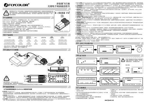
多旋翼飞行器以下的参数需要通过BLHeliSuite32调参软件设置BEC 瞬间电流(散热良好)尺寸(供参考)重量(供参考)锂电节数持续电流(散热良好)型号180A5-12S132g*No82x34x21.1mmX-Cross HV 3-160A160A02 产品规格03 连线/尺寸示意图*图片仅供参考,产品以实物为准04 编程参数值ESC B LHeli -32固件:Flycolor_X_Cross_HV3_G071;*重量包含300mm 长电源线,线长不同重量不同;07注意事项150A 5-12S 132g*No 82x34x21.1mm X-Cross HV 3-120A 120A ●图片仅供参考,产品以实物为准。
为避免短路和漏电,请确保连接处绝缘良好。
●●所有焊接要求良好的焊接技术,任何时候都需要避免因焊接而造成元件或线材之间短路。
1. 启动功率(Rampup power ):启动功率可以设置为从3%-150%的相对值。
这是在启动和提高转速时允许最大功率。
对于低转速,为了便于低反电动势电压检测,最大功率是被限制的。
启动功率也影响双向操作,参数是用来限制在更改转向时的功率。
在启动过程中,实际功率取决于油门输入,可低于设定的最大启动功率,但最低是设定的四分之一。
2. 电机进角(Motor timing ):电机进角可以设置为1°-31°,通常设置中等数值进角即适用于大部分电机,但如果电机运转不顺畅时,可以尝试改变进角。
对于一些高感电机,其换向退磁时间自动 或 较长,尤其在低速运转的时候,电机会在油门快速增加的情况下停转或者不顺畅。
将进角改高会有有助于改善这个现象,因为高进角允许更长的换向退磁时间。
3.PWM 频率 (PWM frequency ): PWM Frequency Low - 低频率在低油门最需要的时候提供良好的主动制动;PWM Frequency High -高频率在更高的油门时使运行更 平稳,或可设置为根据转速变化。
轴承代号含义说明之欧阳术创编
轴承代号含义说明轴承代号由基本代号,前置代号和后置代号构成。
基本代号表示轴承系列及尺寸,前置代号表示轴承类型及轴承零件,位于基本代号之前,后置代号表示轴承的结构,保持架,密封与防尘,公差,油隙,热处理等技术要求,位于基本代号之后。
1.前置代号C- 圆柱滚子轴承附件(或轴承本身),例:C00210 45C- 成对安装圆锥滚子轴承,面对面安装,例:45C30210 46C- 成对安装圆锥滚子轴承,背对背安装,例:46C30210 4CRI- 四列圆柱滚子轴承内圈,例:4CRI4560F 4CRO- 四列圆柱滚子轴承外圈,例:4CRO660AF E- 磁电机球轴承,外径为正公差,例:E10 EN- 磁电机球轴承,外径为负公差,例:EN10 IR- 滚针轴承内圈(英制),例:IR1212 IRA- 滚针轴承内圈,比IR系列宽(英制),例:IRA20 IRM- 滚针轴承内圈,例:IRM710 M- 最大载荷容量型球轴承,例:M6311 OR- 滚针轴承,只有外圈,例:OR10876 F- 深沟球轴承带凸缘,例:F603TR- 尺寸非标准的单列圆锥滚子轴承,例:TR060702 W- 宽型,深沟球轴承,例:W602ZZX2.后置代号(1)内部结构A- 角接触轴承,接触角30度(不标出),例:7210 B- 角接触轴承,接触角40度,例:7210B C- 角接触轴承,接触角15度,例:7210C C- 圆锥滚子轴承,接触角20度,例:30303C D- 圆锥滚子轴承,接触角28度30分,例:30305D G- 压缩轴向油隙的调心和圆锥滚子轴承J- 圆锥滚子轴承,符合ISO分组,例:30206J N- 圆锥滚子轴承,特殊噪声要求,例:30208N R- 加大负荷容量的调心,圆锥和圆柱滚子轴承,例:22228R (2)密封和防尘OR- 球轴承带O型密封圈,例:6201+OR RK- 单面,双唇接触式合成橡胶密封,例:6210RK 2RK- 双面,双唇接触式合成橡胶密封,例:6210.2RK RS- 单面,接触式合成橡胶密封,例:6210RS 2RS- 双面,接触式合成橡胶密封,例:6210-2RS RSA- 单面,带金属罩接触式合成橡胶密封,例:88107RSA 2RSA- 双面,带金属罩接触式合成橡胶密封,例:88107-2RSA RSB- 单面,带加卡金属罩的接触式合成橡胶密封,例:88107RSB2RSB- 双面,带加卡金属罩的接触式合成橡胶密封,例:88107-2RSBRSC- 硅橡胶制RS型密封,例:6210RSCRSD- 聚丙烯橡胶制RS型密封,例:6210RSD RSE- 单面,挡边引导接触式合成橡胶密封,例:6206RSE 2RSE- 双面,挡边引导接触式合成橡胶密封,例:6206-2RSE RSF- RS型氟化橡胶密封,例:6210RSF RU- 单面,非接触式合成橡胶密封,例:6205RU 2RU- 双面,非接触式合成橡胶密封,例:6205-2RU TR- 单面,三唇金属罩合成橡胶密封,例:4508B-TR 2TR- 双面,三唇金属罩合成橡胶密封,例:4508B-2TR U- 一面带接触式合成橡胶密封的滚针轴承,例:NA4916U UU- 二面带接触式合成橡胶密封的滚针轴承,例:NA4916UU Z- 单面钢制防尘盖,例:6205.Z ZZ- 双面钢制防尘盖,例:6205ZZ ZL- 单面,L型内径的钢制防尘盖,例:6207ZL ZX- 单面,由止动环压紧的钢制防尘盖,例:6205ZX ZXL- 由止动环压紧L型内径单面钢制防尘盖,例:6203ZXL ZZL- 钢制防尘盖,双面,L型内径,例:6203ZZL ZZX- 钢制防尘盖,双面,由止动环压紧,例:605ZZX ZZXL- 钢制防尘盖,双面,由止动环压紧,L型内径,例:6303ZZXL(3)套圈形状a- 大于标准倒角的非标准倒角,例:6205a B- 圆锥滚子轴承,外圈带凸缘,例:30210B BI- 双半内圈球轴承,例:6215BI BO- 双半外圈球轴承,例:6215BO D- 圆锥滚子轴承,双外圈或双内圈(英制),例:594/592D K- 带锥孔轴承,锥度为1:12,例:1210K K30- 带锥孔轴承,锥度为1:30,例:23026K30 N- 外圈带止动槽轴承,例:6206N C- 带锁孔的圆锥滚子轴承NR- 外圈带止动环轴承,例:6210NR Y- 小于标准倒角尺寸的非标准倒角,例:30206Y S- 圆锥滚子轴承,非标准倒角(斜倒角)SG- 内径带螺旋槽的圆锥滚子轴承T- 锥孔或锥形外径(英制)圆锥滚子轴承TD- 双列、锥孔或锥形外径(英制)圆锥滚子轴承W- 双内圈、端面带槽的圆锥滚子轴承,例:47T694625WH W- 外圈有润滑油沟槽和孔的圆柱滚子轴承,例:NU316W Wi- 圆柱滚子轴承(1-外圈有润滑油孔;2-内圈有润滑油孔和槽;3-内圈有润滑油孔;4-内、外圈有润滑油孔;5-内、外圈有润滑油孔和槽;6-外圈有润滑油孔和槽,内圈有润滑油孔;10-外圈带锁孔;11-外圈带润滑油孔和锁孔;13-外圈带锁孔,内圈带润滑油孔;14-内圈带润滑油孔,外圈带润滑油孔和锁孔;I=1,2,…)。
亚特诺新一代三相应用接触器产品介绍说明书
Motor control and protectionICON familyStart easily Protect preciselyIntroducing Eaton’s new contactor range for AC-3 applications to 170A. Perfectly suited for applications in the commercial and industrial segments for panel builders and machinery OEMs.The contactor has a smaller footprint than the existing xStart series and offers application adjusted ratings.Icon Contactors SeriesCoil voltages available are 24V50/60HZ, 110V50/60HZ, 230V50/60HZ, 400V50/60HZ, DC24V .Basic devices Rated operational current Max. motor rating for three-phase motors 50 - 60 Hz Conventional thermal current I th = I e AC-1at 40°C A Open Contact AC-3AC-3AC-4380 V 400 V I e220 V 230 V P 380 V 400 V P 660 V 690 V P 220 V 230 V P 380 V 400 V P 660 V 690 V P N/O = Normallyopened contact N/C = Normally 4 pole, 3 poleConnection type: Screw terminals9 2.5 4 4.5 1.5 2.5 3.6 20 – 1 N/C 12 3.5 5.5 6.5 2 3 4.4 20 1 N/O –12 3.5 5.5 6.5 2 3 4.4 20 – 1 N/C 15 4 7.5 7 2 3 4.4 20 1 N/O –154 7.5 7 2 3 4.4 20 – 1 N/C 3 poleConnection type: Screw terminals1857.511 2.5 4.56.5 401 N/O–18 5 7.511 2.5 4.5 6.5 40 – 1 N/C 257.51114 3.5 68.5 401 N/O–25 7.5 1114 3.5 6 8.5 40 – 1 N/C 32101515 4 710 451 N/O–32 10 1515 4 710 45 – 1 N/C 381118.515 4 710 451 N/O–3811 18.5 15 4 710 45 – 1 N/C 3 poleConnection type: Screw terminals40 12.5 18.523 5 912 60 1 N/O 1 N/C 50 15.5 2230 6 1014 80 1 N/O 1 N/C 65 20 3035 7 1217 98 1 N/O 1 N/C 7222 3735 7 1217 98 1 N/O 1 N/C 3 poleConnection type: Screw terminals80 25 3737112015110 1 N/O 1 N/C 95304545 1120151301 N/O1 N/C3 poleConnection type: Screw terminals115 37 5590 17 2843 160 ––150 48 75 96 20 3348 190 ––1705290140 20 3348 203––CMN00027DILM9-01N CMN00038DILM12-10N CMN00049DILM12-01N CMN00060DILM15-10N CMN00071DILM15-01N CMN00082DILM18-10N DILM18-01N CMN00104DILM25-10N DILM25-01N(CMN00126DILM32-10N DILM32-01N CMN00148DILM38-10N DILM38-01N CMN00170DILM40-11N DILM50-11N DILM65-11N DILM72-11N DILM80-11N DILM95-11N DILM115N DILM150N DILM170N (...)(...)(...)(...)(...)(...)(...)(...)(...)(...)(...)(...)(...)(...)(...)(...)(...)(...)(...)(...)(...)(...)• Phase failure sensitivity and temperature compensation • Reset pushbutton manual/auto • Test/off pushbutton• Auxiliary contact (1 N/O + 1 NC)•Fitted directly on the contactor of the maximum current to 175AIcon Overload relays ZB..N series0.1 – 0.16CMN00333CMN00335ZB12N-1,6CMN00336ZB12N-2,4CMN00337ZB12N-4CMN00338ZB12N-6CMN00339ZB12N-10CMN00340ZB12N-12CMN00341ZB12N-161 – 1.5CMN00352ZB32N-24CMN00353ZB32N-30CMN00354ZB32N-36CMN00355ZB32N-38CMN00356Setting range of overload releasesCircuit symbolAuxiliary contactFor use withI r AN/O = normally open contact N/C = normally closed contact0.4 – 0.6 1 N/O 1 N/C 0.6 – 1 1 N/O 1 N/C 1 – 1.6 1 N/O 1 N/C 1.6 – 2.4 1 N/O 1 N/C 2.4 – 4 1 N/O 1 N/C 4 – 6 1 N/O 1 N/C 6 – 10 1 N/O 1 N/C 9 – 12 1 N/O 1 N/C 12 –161 N/O1 N/C 17 – 24 1 N/O 1 N/C 22 – 30 1 N/O 1 N/C 29 – 36 1 N/O 1 N/C 33 – 381 N/O1 N/COverload relaysIcon Overloads ZB…N seriesSetting range of overload releasesCircuit symbolAuxiliary contactFor use withI r AN/O = normally open contact N/C = normally closed contact63 – 80 1 N/O 1 N/C 77 – 971 N/O1 N/C50 – 70 1 N/O 1 N/C 70 – 100 1 N/O 1 N/C 95 – 125 1 N/O 1 N/C 120 – 150 1 N/O 1 N/C 145 – 1751 N/O1 N/COverload relays Part no.Article no.– 25CMN00363– 50– 35– 25 – 50ZB95N-50 – 35ZB150N-35Icon Contactor Relays DILA…N seriesWiring method: Screw terminals Basic devices with interlocked opposing contacts ContactRated operational current AC – 15Conventional thermal current at 55°CN/O = Normally opened contact N/C = Normally closed contact220 V 230 V 240 V I e A380 V 400 V 415 V I e AI th A4 N/O – 4 416 3 N/O 1 N/C 4 4 16 2 N/O 2 N/C 4 4 16 1 N/O 3 N/C 4416–4 N/C4416DILA-40N DILA-31N DILA-22N DILA-13N DILA-04N(Coil voltages available are 24V50/60HZ, 110V50/60HZ, 230V50/60HZ, 400V50/60HZ, DC24V .• Varied 4-pole contact configurations • Conventional thermal current (Ith): 16A• Identical construction sizes for AC- and DC-operated contactor relays •Integrated surge suppressors for DC-operated contactor relaysA complete range of accessories are available for the Icon series, such as:• Auxiliary contacts (top mount)• Auxiliary contacts (side mount)• RC Suppressors• Varistor Suppressors• Pneumatic timer modules • Mechanical Interlocks • Sealable Shrouds•External Reset Button(...)(...)(...)(...)(...)E a t o n10 Kent RoadMascot NSW 2020Tel: 1300 332 866Fax: (02) 9693 1258Email: ************************ Eaton is a registered trademarkof Eaton Corporation.All trademarks are property of their respective owners.For more information about Eaton visit: Eaton’s mission is to improve the quality of life and the environment through the use of power management technologies and services. We provide sustainable solutions that help our customers effectively manage electrical, hydraulic, and mechanical power – more safely, more effi ciently, and more reliably. Eaton’s 2019 revenues were $21.4 billion, and we sell products to customers in more than 175 countries. We have approximately 95,000 employees.For more information about Eaton visit: 。
维沙耶芯片电阻说明书
Document Number: 28744For technical questions, contact: *************************** MCS 0402 VG01, MCT 0603 VG01, MCU 0805 VG01 andMCA 1206 VG01 thin film flat chip resistors with establishedreliability are the perfect choice for all high-reliabilityapplications typically found in military, aircraft and spacecraftelectronics. These versions supplement the families ofprofessional and precision thin film flat chip resistorsMCS 0402, MCT 0603, MCU 0805 and MCA 1206.∙Established reliability, failure rate level E6∙Advanced thin film technology ∙Pure Sn termination on Ni barrier layer ∙Single lot date code ∙Material categorization: For definitions of complianceplease see /doc?99912APPLICATIONS∙Military ∙Avionics ∙Space Notes•These resistors do not feature a limited lifetime when operated within the permissible limits. However, resistance value drift increasing over operating time may result in exceeding a limit acceptable to the specific application, thereby establishing a functional lifetime.•The failure rate level E6 (10-6/h, πQ = 0.3), corresponding to MIL Level P, is superior to level E5 (10-5/h, πQ = 1) and thus may be used as areplacement.METRIC SIZE IMPERIAL0402060308051206EN/CECC RR1005M RR1608M RR2012M RR3216M TECHNICAL SPECIFICATIONSDESCRIPTIONMCS 0402 VG01MCT 0603 VG01MCU 0805 VG01MCA 1206 VG01EN/CECC style (size)RR1005M RR1608M RR2012M RR3216MResistance range10 Ωto 1 M Ω; 0Ω 1 Ωto 1 M Ω; 0ΩResistance tolerance± 1 %; ± 0.1 %T emperature coefficient± 50ppm/K; ± 15 ppm/K Rated dissipation, P 700.063W 0.1W 0.125W 0.25W Operating voltage, U max. AC/DC50V 75 V 150V 200V Permissible film temperature, ϑF max.125︒C Operating temperature range- 55 °C to 125 °C Max. resistance change at P 70for resistance range, |∆R /R| max. after:10 Ωto 1 M Ω 1 Ωto 1 M Ω1000h≤ 0.25 %8000h≤ 0.5 %225000h≤ 1.5 %Permissible voltage against ambient(insulation):1 min; U ins75V 100V 200V 300V Continuous75V 75V 75V 75V Assessed failure rate levelE6 = 10-6/h Quality factor, πQ0.3Failure rate: FIT observed < 0.1 x 10⁻⁹/h For technical questions, contact: ***************************Document Number: 28744Notes•The products can be ordered using either the PART NUMBER or the PRODUCT DESCRIPTION.•Products within a packaging unit are single lot date code.TYPE/SIZEVERSION TCR RESISTANCE TOLERANCE PACKAGING MCS 0402MCT 0603MCU 0805MCA 1206H = EN 140401-801,“Version E”;failure rate level E6 C = ± 50 ppm/K E = ± 15 ppm/K Z = Jumper 3 digit value 1 digit multiplier MULTIPLIER8 = *10-29 = *10-10 = *1001 = *1012 = *1023 = *1034 = *1040000 = Jumper F = ± 1 %B = ± 0.1 %Z = JumperE1E0P1P5Product Description: MCT 0603-50 1% VG01 P5 287KProduct Description: MCT 0603 VG01 P5 0R0MCT 0603-50 1 %VG01P5287K MCT 0603--VG01P50R0TYPE/SIZETCR T OLERANCE VERSION PACKAGING RESISTANCE MCS 0402MCT 0603MCU 0805MCA 1206± 50 ppm/K ± 15 ppm/K ± 1 %± 0.1 %VG01 = EN 140401-801,“Version E”;failure rate level E6E1E0P1P549R9 = 49.9 Ω287K = 287 k Ω0R0 = JumperMC T 0603H Z 0000Z P 50006032873500Document Number: 28744For technical questions, contact: *************************** Note•The ordering information according to EN 140401-801:2007 shown above succeeds and replaces the ordering information according to earlier versions of the detail specification EN 140401-801 or its predecessor CECC 40401-801, for example:CECC 40401-801 EZ RR1608M C 287K F E6CECC 40401-801 S RR1608M C 287K F E6with EZ; S Assessment level, where EZ is successor to and superior replacement for SRR1608M Style, with suffix M for “metric”C Temperature coefficient, according to the detail specificationC = ± 50 ppm/K; E = ± 15 ppm/K Note•According to EN 140401-801, resistance values are to be selected from the E96 series for ±1% tolerance and from the E192 series for ±0.1 % tolerance.EN140401-801EZRR1608M-0R00-E6The elements used in the component number have the following meaning:EN140401-801EZRR1608MR287KF E6EN detail specification number Assessment level for the zero-defect approach Style (size)T emperature coefficient, according to EN 60062R = ± 50 ppm/K; P = ± 15 ppm/K Resistance, according to EN 60062, 4 characters T olerance on rated resistance, according to EN 60062F = ± 1 %; B = ± 0.1 %Failure rate level according to EN 60115-1, annex ZRTEMPERATURE COEFFICIENT AND RESISTANCE RANGEDESCRIPTIONRESISTANCE TCRTOLERANCE MCS 0402 VG01MCT 0603 VG01MCU 0805 VG01MCA 1206 VG01± 50 ppm/K± 1 %10 Ωto 1 M Ω 1 Ωto 1 M Ω1Ωto 1 M Ω1Ωto 1 M Ω± 15 ppm/K± 0.1 %100Ωto 33.2 k Ω100Ωto 47.5 k Ω100Ωto 100k Ω43.2Ωto 332k ΩJumper ≤ 20m Ω; I max. = 0.63 A ≤ 20m Ω; I max. = 1 A ≤ 20m Ω; I max. = 1.5 A≤ 20m Ω; I max. = 2 A PACKAGINGTYPECODE QUANTITY CARRIER TAPE WIDTH PITCH REEL DIAMETER MCS 0402 VG01E11000Paper tape acc. IEC 60286-3T ype I 8 mm 2 mm 180 mm/7"E010 000MCT 0603 VG01P110008 mm 4 mm P55000MCU 0805 VG01P11000P55000MCA 1206 VG01P11000P55000 For technical questions, contact: ***************************Document Number: 28744Note•Resistors MCA 1206 VG01 and MCU 0805 VG01 are marked using to the four-character code system of IEC 60062, 4.2.3.Resistors MCT 0603 VG01 and MCS 0402 VG01 do not show any marking on their light blue protective coating.Note•The given solder pad dimensions reflect the considerations for board design and assembly as outlined e.g. in standards IEC 61188-5-x, or in publication IPC 7351. They do not guarantee any supposed thermal properties, however, they will be found adequate for most general applications.DIMENSIONS AND MASSTYPEH (mm)L (mm)W (mm)W T (mm)T b (mm)T t (mm)MASS (mg)MCS 0402 VG010.32 ± 0.05 1.0 ± 0.050.5 ± 0.05> 75 % of W 0.2 ± 0.10.2 + 0.1/- 0.150.6MCT 0603 VG010.45 + 0.1/- 0.05 1.55 ± 0.050.85 ± 0.10.3 + 0.15/- 0.21.9MCU 0805 VG010.45 + 0.1/- 0.052.0 ± 0.11.25 ± 0.150.4 + 0.1/- 0.2 4.6MCA 1206 VG010.55 ± 0.1 3.2 + 0.1/- 0.2 1.6 ± 0.150.5 ± 0.259.2RECOMMENDED SOLDER PAD DIMENSIONSTYPE WAVE SOLDERINGREFLOW SOLDERING G(mm)Y (mm)X (mm)Z (mm)G (mm)Y (mm)X (mm)Z(mm)MCS 0402 VG01----0.350.550.55 1.45MCT 0603 VG010.551.10 1.102.750.650.700.95 2.05MCU 0805 VG010.801.25 1.50 3.300.900.90 1.402.70MCA 1206 VG011.40 1.50 1.90 4.40 1.50 1.15 1.753.80grade ceramic (Al2O3) substrate and conditioned to achieve the desired temperature coefficient. Specially designed inner contacts are deposited on both sides. A special laser is used to achieve the target value by smoothly cutting a meander groove in the resistive layer without damaging the ceramics. For the high ohmic range, optimized cermet products provide comparable properties. The resistor elements are covered by a protective coating designed for electrical, mechanical and climatic protection. The terminations receive a final pure tin on nickel plating.The result of the determined production is verified by an extensive testing procedure performed on 100 % of the individual resistors. This includes pulse load screening for the elimination of products with a potential risk of early life failures according to EN 140401-801, 2.1.2.2 (feasible for R≥ 10 Ω). Only accepted products are laid directly into the paper tape in accordance with EN 60286-3 (3), Type I.Products within a packaging unit are from the same production lot and carry the same date code.ASSEMBLYThe resistors are suitable for processing on automatic SMD assembly systems. They are suitable for automatic soldering using wave, reflow or vapour phase as shown in IEC61760-1 (3). Solderability is specified for 2 years after production or requalification. The permitted storage time is 20 years.The resistors are RoHS compliant; the pure tin plating provides compatibility with lead (Pb)-free soldering processes. The immunity of the plating against tin whisker growth has been proven under extensive testing.The encapsulation is resistant to all cleaning solvents commonly used in the electronics industry, including alcohols, esters and aqueous solutions. The suitability of conformal coatings, if applied, shall be qualified by appropriate means to ensure the long-term stability of the whole system.∙2000/53/EC End of Vehicle life Directive (ELV) and Annex II (ELV II)∙2011/65/EU Restriction of the use of Hazardous Substances directive (RoHS)∙2002/96/EC Waste Electrical and Electronic Equipment Directive (WEEE)APPROVALSThe resistors are approved within the IECQ-CECC Quality Assessment System for Electronic Components to the detail specification EN140401-801 which refers to EN60115-1, EN140400 and the variety of environmental test procedures of the IEC 60068 (3)series.Conformity is attested by the use of the CECC logo () as the mark of conformity on the package label.Vishay BEYS C HLAG has achieved “Approval of Manufacturer” in accordance with IEC QC001002-3, clause 2. The release certificate for “Technology Approval Schedule” in accordance with CECC240001 based on IEC QC001002-3, clause 6 is granted for the Vishay BEYSCHLAG manufacturing process.The Vishay BEYSC HLAG production facility is registered with the CAGE code D9539.RELATED PRODUCTSA wider range of TCR, tolerance and resistance values, plus the option of values from a different E series is available with products approved to EN 140401-801, Version A, without established reliability, nominal failure rate level E0 (quality factor πQ = 3). See the datasheets:∙“Professional Flat Chip Resistors”(/doc?28705)∙“Precision Flat Chip Resistors”(/doc?28700)Notes(1)Global Automotive Declarable Substance List, see .(2)CEFIC (European Chemical Industry Council), EECA (European Electronic Component Manufacturers Association), EICTA (European tradeorganisation representing the information and communications technology and consumer electronics), see /index.php?id=1053&id_article=340.(3)The quoted IEC standards are also released as EN standards with the same number and identical contents.Document Number: 28744For technical questions, contact: *************************** For technical questions, contact: ***************************Document Number: 28744Document Number: 28744For technical questions, contact: *************************** •“Precision Flat Chip Resistors”, document no. 28700EN 140400, sectional specificationEN 140401-801, detail specificationFor further information on the tests and requirements ofthese products please refer to the specifications mentionedabove, and to the following datasheets:•“Professional Flat Chip Resistors”(/doc?28705)•“Precision Flat Chip Resistors”(/doc?28700)HISTORICAL 12NC INFORMATION∙The resistors had a 12-digit code starting with 2312∙The subsequent 4 digits indicated the resistor type,specification and packaging; see the 12NC table∙The remaining 4digits indicate the resistance value:-The first 3digits indicated the resistance value-The last digit indicated the resistance decade inaccordance with the resistance decade table RESISTANCE DECADE Historical 12NC ExampleThe 12NC of a MC T 0603 VG01 resistor, value 287K andTCR 50 with ± 1 % tolerance, supplied in cardboard tape of5000units per reel was: 2312 215 02874.RESISTANCE DECADE LAST DIGIT 1Ω to 9.99Ω810Ω to 99.9Ω9100Ω to 999Ω11 k Ωto 9.99k Ω210k Ω to 99.9k Ω3100k Ω to 999k Ω41M Ω5HISTORICAL 12NC - Resistor type and packagingDESCRIPTION2312........CARDBOARD TAPE ON REEL TYPE TCRTOL.E1 1000 PIECES E0 10 000 PIECES MCS 0402 VG01± 50 ppm/K± 1 %260 0....275 0....± 15 ppm/K± 0.1 %262 0....277 0....Jumper262 90001277 90001TYPE TCRTOL.P11000 PIECES P5 5000 PIECES PW 20 000 PIECES MCT 0603 VG01± 50 ppm/K± 1 %200 0....215 0....205 0....± 15 ppm/K± 0.1 %202 0....217 0....-Jumper202 90001217 90001207 90001MCU 0805 VG01± 50 ppm/K±1 %240 0....255 0....245 0....± 15 ppm/K± 0.1 %242 0....257 0....-Jumper242 90001257 90001247 90001MCA 1206 VG01± 50 ppm/K± 1 %No 12NC assigned to MCA 1206 VG01± 15 ppm/K± 0.1 %Jumper“Vishay”), disclaim any and all liability for any errors, inaccuracies or incompleteness contained in any datasheet or in any other disclosure relating to any product.Vishay makes no warranty, representation or guarantee regarding the suitability of the products for any particular purpose or the continuing production of any product. To the maximum extent permitted by applicable law, Vishay disclaims (i) any and all liability arising out of the application or use of any product, (ii) any and all liability, including without limitation special, consequential or incidental damages, and (iii) any and all implied warranties, including warranties of fitness for particular purpose, non-infringement and merchantability.Statements regarding the suitability of products for certain types of applications are based on Vishay’s knowledge of typical requirements that are often placed on Vishay products in generic applications. Such statements are not binding statements about the suitability of products for a particular application. It is the customer’s responsibility to validate that a particular product with the properties described in the product specification is suitable for use in a particular application. Parameters provided in datasheets and/or specifications may vary in different applications and performance may vary over time. All operating parameters, including typical parameters, must be validated for each customer application by the customer’s technical experts. Product specifications do not expand or otherwise modify Vishay’s terms and conditions of purchase, including but not limited to the warranty expressed therein.Except as expressly indicated in writing, Vishay products are not designed for use in medical, life-saving, or life-sustaining applications or for any other application in which the failure of the Vishay product could result in personal injury or death. Customers using or selling Vishay products not expressly indicated for use in such applications do so at their own risk. Please contact authorized Vishay personnel to obtain written terms and conditions regarding products designed for such applications. No license, express or implied, by estoppel or otherwise, to any intellectual property rights is granted by this document or by any conduct of Vishay. Product names and markings noted herein may be trademarks of their respective owners.Material Category PolicyVishay Intertechnology, Inc. hereby certifies that all its products that are identified as RoHS-Compliant fulfill the definitions and restrictions defined under Directive 2011/65/EU of The European Parliament and of the Council of June 8, 2011 on the restriction of the use of certain hazardous substances in electrical and electronic equipment (EEE) - recast, unless otherwise specified as non-compliant.Please note that some Vishay documentation may still make reference to RoHS Directive 2002/95/EC. We confirm that all the products identified as being compliant to Directive 2002/95/EC conform to Directive 2011/65/EU.Vishay Intertechnology, Inc. hereby certifies that all its products that are identified as Halogen-Free follow Halogen-Free requirements as per JEDEC JS709A standards. Please note that some Vishay documentation may still make reference to the IEC 61249-2-21 definition. We confirm that all the products identified as being compliant to IEC 61249-2-21 conform to JEDEC JS709A standards.Revision: 02-Oct-121Document Number: 91000。
NCC日本化工电容规格书
铝电解电容器
产品指南
接前页
标 准
小 型 ·
低
长 寿
高 信 形状
品
薄 型 化
Z化 命
赖 性
工作上限温度· 标准寿命 (hours)
额定电压范围 (Vdc)
04 105℃
3,000 6.3 ~ 50
04 125℃ 3,000/5,000 25 ~ 50
04 125℃ 2,000~5,000 10 ~ 450
2,000 6.3 ~ 100
692 105℃
2,000 6.3 ~ 100
692 85℃
2,000 160 ~ 400
692 105℃
2,000 160 ~ 400
692 105℃
7,000 160 ~ 450
692 105℃
5,000 160 ~ 450
692 105℃
5,000 160 ~ 450
331 85℃
5,000 350 ~ 450
331 85℃
2,000 350 ~ 550
331 85℃
2,000 350 ~ 550
331 85℃
5,000 350 ~ 450
331 85℃
20,000 350 ~ 450
331 85℃
5,000 63~100、350~450
331 105℃ 2,000/5,000 10 ~ 525
04 85℃
1,000 4 ~ 50
04 105℃
1,000 4 ~ 50
04 85℃
1,000 4 ~ 63
04 105℃
1,000 4 ~ 63
04 85℃
2,000 6.3 ~ 450
维萨拉暖通空调传感器产品介绍说明书

维萨拉暖通空调传感器为您带来理想室内空气质量/ 客户案例DOCUMENT TYPE HEADLINEInfosys 是印度第二大IT咨询公司,在全球拥有 200,000 多名员工,营收超过 100 亿美元。
该公司总部位于班加罗尔,在印度设立的开发中心逾 16 家,另在中国设有一家园区。
目前,Infosys 在其所有自建园区及办公楼宇项目中使用的均是维萨拉暖通空调传感器。
Infosys 总部位于印度班加罗尔。
机械通风系统需要能进行精确测量的暖通空调传感器Infosys 秉承“正确的管理基于精确的测量”的信条。
这 16 个园区的总建筑面积达 4400 万平方英尺,其中大Infosys 基础设施团队区域经理 Vikas Makkar 先生表示:“我们发现维萨拉的独特之处在于,暖通空调产品具有 5 年稳定性提高了员工的生产率,从而使得员工可以为客户提供高质量的解决方案。
迈索尔园区的 Infosys 全球教育中心 (GEC)(印度迈索尔)继续说道:“我们认为这些传感器是我们在楼宇管理系统(如需求控制通风、www .vaisala.c nRef. B211716ZH-A -R ©Vaisala 2018本资料受到版权保护,所有版权为V a i s a l a 及其合伙人所有。
版权所有,任何标识和/或产品名称均为Vaisala及其合伙人的商标。
事先未经Vaisala的书面许可,不得以任何形式复制、转印、发行或储存本手册中所包含的信息。
所有规格,包括技术规格,若有变更,恕不另行通知。
此文本原文为英文,若产生歧义, 请以英文版为准。
更多详情,请访问 www .vaisala.c n , 或联络我们:**********************维萨拉工业测量部客户支持电话:400 810 0126扫描二维码,获取更多信息所使用的 HVAC 产品到目前为止,Infosys 主要将维萨拉传感器(即 H M D110、GM D20、GM W90 系列、H M W90 系列和 GMT220 系列)应用于温度、湿度及二氧化碳测量。
常用器件知识

测得如上数据,此硅桥基本是好的。
五、场管
型号
额定电流 K2611 K1358 K3878 K2847 K4207 K1168/1167 K2698 9 9 9 8 13 15 15
参数
额定电压 900 900 900 900 900 500 500
K4107
K3235 K2370
15
15 20
500
13
13 14
960
800 800
测量方法:
至万用表为二极管档:
场管9Z24是一P沟道型 红笔接② 黑笔接③ ,测得压降约为0.5400
1 2 3 1 2 3
源 极
G
场管Z24是一N沟道型 黑笔接② 红笔接③ ,测得压降约为0.5300
S S
P 沟 道
漏 极
D
G
N 沟 道
测得如上数据,此场管基本是好的。
5 2
2.黑表笔接④ 红表笔依次接① ②③,测量压降均约为0.4400 3.黑表笔接④ 红表笔接⑤ ,测量压降约为0.800
4 3
测得如上数据,此三相整流桥基本是好的。
二、IGBT
型号
额定电流
FF100R12KS4(快速) FF150R12KS4(快速) FF200R12KS4(快速) BSM100GB120D BSM150GB120D BSM200GB120D FGL60N100BNTD(单管) 100A 150A 200A 100A 1 B
C E B C E B C
8550是PNP型三极管 黑笔接B极,红笔依次接E极与C极,测得压降均约0.7000
B
E
C
B
E
C
测得如上数据,此三极管基本是好的。
NACV中文资料
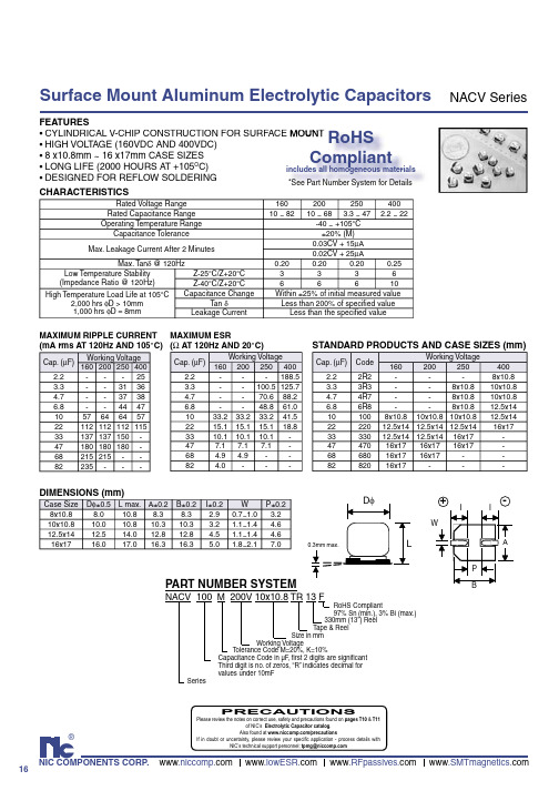
DIMENSIONS (mm)
Case Size 8x10.8 10x10.8 12.5x14 16x17 Dφ±0.5 8.0 10.0 12.5 16.0 L max. A±0.2 10.8 8.3 10.8 10.3 14.0 12.8 17.0 16.3 B±0.2 8.3 10.3 12.8 16.3 I±0.2 2.9 3.2 4.5 5.0 W 0.7~1.0 1.1~1.4 1.1~1.4 1.8~2.1 P±0.2 3.2 4.6 4.6 7.0
MAXIMUM ESR MAXIMUM RIPPLE CURRENT (mA rms AT 120Hz AND 105°C) (Ω AT 120Hz AND 20°C)
Working Voltage Cap. (µF) 160 200 250 400 2.2 25 3.3 31 36 4.7 37 38 6.8 44 47 10 57 64 64 57 22 112 112 112 115 33 137 137 150 47 180 180 180 68 215 215 82 235 Cap. (µF) 2.2 3.3 4.7 6.8 10 22 33 47 68 82 Working Voltage 160 200 250 400 188.5 100.5 125.7 70.6 88.2 48.8 61.0 33.2 33.2 33.2 41.5 15.1 15.1 15.1 18.8 10.1 10.1 10.1 7.1 7.1 7.1 4.9 4.9 4.0 -
160 10 ~ 82
200 250 400 10 ~ 68 3.3 ~ 47 2.2 ~ 22 -40 ~ +105°C ±20% (M) 0.03CV + 15µA 0.02CV + 25µA 0.20 0.20 0.20 0.25 3 3 3 6 6 6 6 10 Within ±25% of initial measured value Less than 200% of specified value Less than the specified value
进口轴承代号汇总

轴承型号、代号知识汇总目录1 轴承的基本知识 (1)2 基本代号进口轴承 (2)2.1 基本代号 (2)2.2 后置代号 (2)2.3 前置代号 (3)3 NSK轴承前置代号含义 (3)3.1 深沟球轴承 (3)3.2 调心球轴承 (4)3.3 调心滚子轴承 (4)3.4 圆锥滚子轴承 (4)3.5 圆柱滚子轴承 (4)3.6 角接触球轴承 (5)3.7 滚珠丝杠支撑用轴承 (5)3.8 推力角接触球轴承 (5)4 NSK后置代号 (5)4.1 INA/FAG轴承(后置)代号 (8)4.2 后置代号—轴承外形尺寸及外部结构 (8)4.3 后置代号——密封与防尘 (9)4.4 后置代号—保持架及其材料 (9)4.5 后置代号—无保持架轴承 (11)4.6 后置代号—游隙 (11)5 SKF轴承代号说明: (14)5.1 前置代号 (14)5.2 后置代号 (14)5.2.1 单列角接触球轴承 (15)5.2.2 双列角接触球轴承 (15)5.2.3 圆柱滚子轴承 (15)6 有关轴承公差等级的表示字母: (21)7 FAG轴承公司的FAG轴承代号 (22)7.1 后置代号—保持架及其材料 (24)7.2 后置代号—游隙 (26)7.3 后置代号—测试噪声的FAG轴承 (27)7.4 后置代号—特殊技术条件 (27)7.5 后置代号—特殊技术条件 (27)7.6 后置代号—成对轴承和机床主轴FAG轴承 (27)7.7 通用配对型FAG轴承 (28)7.8 后置代号—机床主轴FAG轴承 (28)7.9 FAG轴承后置代号—特殊意义的符号 (29)1 轴承的基本知识1.1滚动轴承:在支承负荷和彼此相对运动的零件间作滚动运动的轴承,它包括有滚道的零件和带或不带隔离或引导件的滚动体组。
可用于承受径向、轴向或径向与轴向的联合负荷。
1.2角接触轴承:球与套圈公称接触角大于0°,而小于90°的滚动轴承。
DFK 33GP1300 技术手册说明书
技术细节1.要件速览 42.尺寸图 6 2.1DFK 33GP1300 带脚架适配器的C型接口 (6)2.2DFK 33GP1300 不带脚架适配器的C型接口 (7)2.3DFK 33GP1300 带脚架适配器的CS型接口 (8)2.4DFK 33GP1300 不带脚架适配器的CS型接口 (9)3.I/O 连接器 10 3.16-pin I/O 连接器 (10)3.1.1TRIGGER_IN (10)3.1.2STROBE_OUT (11)4.光谱特征 12 4.1红外截止滤波器 (12)4.2光谱灵敏度 - P1300 (12)5.相机控制 13 5.1传感器读出控制 (13)5.1.1像素格式 (13)8-Bit Bayer Raw (13)5.1.1.15.1.1.212-Bit Packed Bayer Raw (14)16-Bit Bayer Raw (14)5.1.1.35.1.1.4YUV 4:2:2 (14)5.1.1.5YUV 4:1:1 (14)5.1.2分辨率 (14)5.1.3读出模式 (15)5.1.4帧速率 (15)5.1.5局部扫描偏移 (17)5.2图像传感器控制 (18)5.2.1曝光时间 (18)5.2.2增益 (18)5.3自动曝光及增益控制 (18)5.3.1自动曝光 (19)5.3.2自动增益 (19)自动参考值 (19)5.3.35.3.4强光缩减 (19)5.3.5自动曝光限制 (20)5.3.6自动增益限制 (20)5.4触发 (21)5.4.1触发模式 (21)5.4.2触发极性 (21)5.4.3软件触发 (22)5.4.4触发脉冲计数 (22)5.4.5触发源 (22)5.4.6触发重叠 (23)5.5触发定时参数 (23)5.5.1触发延迟 (23)5.5.2触发去抖时间 (23)5.5.3触发遮罩时间 (24)5.5.4触发噪声抑制时间 (24)5.6数字I/O (24)5.6.1通用输入 (24)5.6.2通用输出 (25)5.7频闪 (25)5.7.1频闪启用 (25)5.7.2频闪极性 (26)5.7.3频闪操作 (26)5.8白平衡 (26)5.8.1自动白平衡 (26)5.8.2白平衡模式 (27)手动白平衡 (28)5.8.35.9图像处理 (29)5.9.1伽玛 (29)5.9.2查找表 (29)5.10色彩处理 (30)5.10.1色调 (31)5.10.2饱和 (31)5.10.3色彩校正矩阵 (31)5.11自动功能感兴趣的区域 (33)5.11.1自动功能ROI启用 (33)自动功能ROI预设 (34)5.11.25.11.3自动功能ROI自定义矩形 (34)5.12用户设置 (35)5.12.1用户设置选择器 (35)5.12.2加载用户设置 (35)5.12.3保存用户设置 (36)默认用户配置 (36)5.12.46.Rev i s i o n H i story 371要件速览2尺寸图2.1DFK 33GP1300 带脚架适配器的C型接口2.4DFK 33GP1300 不带脚架适配器的CS型接口3I/O 连接器3.16-pin I/O 连接器相机后视图1开极闸M OS F E T最大限制0.2A(ID)!2启动电流最低条件3.5mA!3 G:地O:输出I:输入3.1.1TR IGG ER_I NTRIGGER_IN线可用于将曝光时间的开始与外部事件同步。
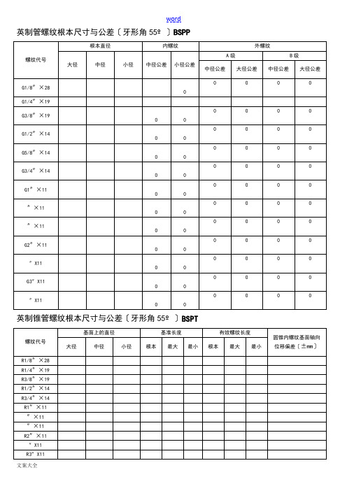
螺纹基本尺寸对照表
英制管螺纹根本尺寸与公差〔牙形角55º〕BSPP英制锥管螺纹根本尺寸与公差〔牙形角55º〕BSPT美制管螺纹根本尺寸与公差〔牙形角60º〕UN(F)公制螺纹根本尺寸与公差(牙形角60º)M55°圆锥管螺纹根本尺寸对照表最新下载-汇兴达55°圆锥管螺纹根本尺寸对照表最新下载-汇兴达55°圆锥管螺纹(BSPT)R66" 11聊城市鑫茂祥管业某某专业经营钢管规格:5mm*1mm—1020mm*200mm合金钢管、外径22mm-127mm冷轧无缝钢管、外径127mm-600mm,壁厚16mm-100mm,外径精度±0.5%,壁厚精度±5%热轧中厚壁无缝钢管、16Mn外径400—1600mm、壁厚20—60mm的大口径厚壁卷管,可定尺到16米与各种规格的无缝方管、异型无缝钢管等.常备钢管种类有:构造用无缝钢管、流体用无缝钢管、液压无缝钢管、电力用无缝钢管、石油输送用无缝钢管、化肥设备用无缝钢管、煤矿用无缝钢管、不锈钢无缝钢管、化工用无缝钢管、纺织机械用无缝钢管、汽车;水利用无缝钢管,精细无缝钢管、光亮无缝钢管、军工医疗用无缝钢管、管道用无缝钢管、支柱用无缝钢管、合金无缝管、高压无缝管、大口径直缝焊管等。
适用于工程、煤矿、纺织、电力、锅炉、机械、军工等各个领域。
公司以良好的信用、优质的产品、雄厚的实力、低廉的价钱享誉全国30多个省、市、自治区、直辖市与国外,产品深得用户依赖。
公司常年销售某某钢铁集团、冶钢集团、某某钢厂、宝钢集团、鞍钢集团、某某大无缝、某某特钢厂、某某钢厂、某某钢厂等各大钢厂生产的各种无缝钢管与合金管。
主营材质:20#、35#、45#、20G、20A、40Mn2、45Mn2、27SiMn、40MnB、20MnVB、20Cr、30Cr、35Cr、40Cr、45Cr、50Cr、 38CrSi、12CrMo 、20CrMo、35CrMo、42CrMo、12CrMoV、12Cr1MoV、38CrMoAL、50CrV、20CrMnSi、30CrMnSi、35CrMnSi、 20CrMnTi、30CrMnTi、12CrNi2、 12CrNi3、12Cr2Ni4、40CrNiMoA、45CrNiMoVA、20G、20MnG、25MnG、12CrMoG、15CrMoG、12Cr2MoG、12Cr1MoVG、12Cr2MoWVTiB、12Cr3MoVSiTiB等实行标准:GB/T8162-99构造管、GB/T8163-99流体管、GB/T3087-99中低压锅炉管、GB/T5310-95高压锅炉管、GB/T6479-2000化肥专用管、27SiMn液压支架管、高压合金管、GB/T9948-85石油裂化管GB9948-88、地质钻探用管YB235-70、汽车半轴套管YB/T5035-96。
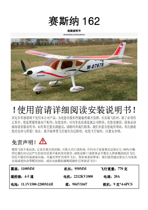
塞斯纳162组装说明书
As shown in the red line shows position of
Installed into the front landing gear in the
foam coated with glue
wheel cover
把起落架整流条装入机轮罩中,对接 把爪牙螺母钉入到图片中的木片,钉 选出以上木片,准备装入机身中
选出两条管子,安装机身中如右图红 把机翼台安装到机身中,并在机身四 把图片中所示木片安装到机身相应 红所示,一边一条用胶水固定。 周与另外一边接触面涂上泡沫胶水。 位置中
Elect two tubes on the body shown in red at Install the wing to the fuselage in Taiwan and Shown in the picture into the body wood chips
并把起落架罩流条安装上
And the landing gear cover on the flow of the installation
装好如图
Installed as shown in Figure
另一边的安装方法相同,装好后如图
The other side of the installation the same way, after installed as shown in Figure
Note installation direction of the battery cover
circle position
when the magnet is not in the middle of wood
chips
安装后如图
Installed as shown in Figure
AVX钽电容简单规格认识及全部型

2000
PCS
71
贴片钽电容
钽电容
TAJB685K060RNJ
±10% 6.8UF 10V 10% 1210
AVX
2000
PCS
72
贴片钽电容
钽电容
TAJB685M060RNJ
±20% 6.8UF 10V 20% 1210
AVX
2000
PCS
73
贴片钽电容
钽电容
TAJB335K020RNJ
±10% 3.3UF 20V 10% 1210
AVX
2000
PCS
56
贴片钽电容
钽电容
TAJA225M006RNJ
±20% 2.2UF 6.3V 20% 1206
AVX
2000
PCS
57
贴片钽电容
钽电容
TAJA156M006RNJ
±20% 15UF 6.3V 20% 1206
AVX
2000
PCS
58
贴片钽电容
钽电容
TAJA335M066RNJ
±20% 3.3UF 16V 20% 1206
AVX
2000
PCS
59
贴片钽电容
钽电容
TAJA475M020RNJ
±20% 4.7UF 20V 20% 1206
AVX
2000
PCS
60
贴片钽电容
钽电容
TAJA225K025RNJ
±10% 2.2UF 25V 10% 1206
AVX
2000
PCS
61
贴片钽电容
钽电容
TAJA475K020RNJ
±10% 4.7UF 20V 10% 1206
NACV6R8K250V12.5x14TR13F中文资料

16®NIC COMPONENTS CORP. www www www www .SMTmagnetics.comSurface Mount Aluminum Electrolytic CapacitorsNACV SeriesFEATURES•CYLINDRICAL V-CHIP CONSTRUCTION FOR SURFACE MOUNT •HIGH VOLT AGE (160VDC AND 400VDC)•8 x10.8mm ~ 16 x17mm CASE SIZES •LONG LIFE (2000 HOURS A T +105O C)•DESIGNED FOR REFLOW SOLDERING CHARACTERISTICSDIMENSIONS (mm)CE MOUNT RoHSCompliantincludes all homogeneous materials *See Part Number System for DetailsNACV 100 M 200V 10x10.8 TR 13 FRoHS Compliant97% Sn (min.), 3% Bi (max.) 330mm (13”) Reel Tape & Reel Size in mm Working VoltageT olerance Code M=20%, K=10% Capacitance Code in µF , fi rst 2 digits are signifi cant Third digit is no. of zeros, “R” indicates decimal for values under 10mF SeriesPART NUMBER SYSTEM0.3mm max.D φL+ -IIWPABSTANDARD PRODUCTS AND CASE SIZES (mm)MAXIMUM RIPPLE CURRENT(mA rms AT 120Hz AND 105°C)MAXIMUM ESR (Ω AT 120Hz AND 20°C)Rated Voltage Range 160200250400Rated Capacitance Range 10 ~ 8210 ~ 68 3.3 ~ 47 2.2 ~ 22Operating Temperature Range-40 ~ +105°C Capacitance Tolerance ±20% (M)Max. Leakage Current After 2 Minutes0.03CV + 15µA 0.02CV + 25µAMax. Tan δ @ 120Hz0.200.200.200.25Low Temperature Stability(Impedance Ratio @ 120Hz)Z-25°C/Z+20°C 3336Z-40°C/Z+20°C66610High Temperature Load Life at 105°C2,000 hrs φD > 10mm 1,000 hrs φD = 8mm Capacitance Change Within ±25% of initial measured value Tan δLess than 200% of specifi ed value Leakage CurrentLess than the specifi ed valueCap. (µF)Working Voltage 1602002504002.2---253.3--31364.7--37386.8--444710576464572211211211211533137137150-47180180180-68215215--82235---Cap. (µF)Working Voltage 1602002504002.2---188.53.3--100.5125.74.7--70.688.26.8--48.861.01033.233.233.241.52215.115.115.118.83310.110.110.1-477.17.17.1-68 4.9 4.9--824.0---Cap. (µF)Code Working Voltage1602002504002.22R2---8x10.83.33R3--8x10.810x10.84.74R7--8x10.810x10.86.86R8--8x10.812.5x14101008x10.810x10.810x10.812.5x142222012.5x1412.5x1412.5x1416x173333012.5x1412.5x1416x17-4747016x1716x1716x17-6868016x1716x17--8282016x17---Case Size D φ±0.5L max.A±0.2B±0.2I±0.2W P±0.28x10.88.010.88.38.3 2.90.7~1.0 3.210x10.810.010.810.310.3 3.2 1.1~1.4 4.612.5x1412.514.012.812.8 4.5 1.1~1.4 4.616x1716.017.016.316.35.01.8~2.17.0PRECAUTIONSPlease review the notes on correct use, safety and precautions found on pages T10 & T11of NIC’s Electrolytic Capacitor catalog . Also found at /precautionsIf in doubt or uncertainty, please review your specifi c application - process details withNIC’s technical support personnel: tpmg@元器件交易网。
进口3K氯压机资料

安装及操作说明名称:透平压缩机系统型号:3(2)VRZ 250/430/16 G序言本安装和操作说明是对3(2)VRZ 250/430/16 G 型透平压缩机开车、操作、维修的重要描述。
因此,在初次开车前,你必须认真阅读安装和操作说明以及LCP的操作手册,已确保安全、经济的使用此透平压缩机。
压缩机的关键部件,例如电机、齿轮单元、油冷器、油过滤器、油泵等也必须遵守此操作说明。
所有的维修活动必须由相关的专家进行。
由于操作疏忽或者维修不当而造成的设备故障,我们将不接受任何质保要求。
我们将为你解决你在此安装和操作说明中遇到的任何问题。
我们希望你们能在不出现任何问题的情况下顺利运行这套系统。
目录表格清单 (6)图纸清单 (6)简介 (7)用途 (7)1.安全规程及说明 (8)1.1安全规程................................................................................. .8 1.2安全说明. (8)1.3重点 (10)2.技术资料 (11)2.1压缩机 (11)2.2与压缩机相连的冷却器............................................................. (16)2.2.1冷却器 (16)2.2.2连接管道 (16)2.2.3冷却器使用的弹簧垫圈........................................................ (16)2.3电机 (16)2.4增速器 (17)2.5联轴器 (17)2.6设备底座 (17)2.7润滑油系统 (18)2.7.1油箱 (18)2.7.2油冷却器 (18)2.7.2.1辅助油泵 (19)2.7.2.2油冷却器 (19)2.7.2.3油过滤器 (19)2.8设备底座、油系统和油冷却器的安装 (20)2.9消耗定额............................................................................. (20)2.9.1润滑油.......................................................................... (20)2.9.1.1过滤油量..................................................................... (20)2.9.1.2润滑油量.................................................. (21)2.9.2密封气.............................................. (22)2.9.3电力消耗....................................................................... (22)2.9.3.1压缩机电机.................................................................. (22)2.9.3.2辅助油泵电机 (22)2.9.3.3油箱加热器 (22)3.压缩机组的各部件名称及功能 (23)3.1压缩机.............................................. . (23)3.1.1压缩机的一般资料 (23)3.1.2设计说明 (27)3.1.2.1转子 (33)3.1.2.2机壳 (33)3.1.2.3导轮和迷宫密封.............................................. . (33)3.1.2.4压缩机转子轴承的安装 (33)3.1.3中冷器和后冷器 (34)3.2驱动系统 (34)3.2.1电机 (34)3.2.2增速器 (34)3.2.3联轴器 (34)3.3润滑油供应 (35)3.4测量和控制技术 (39)3.4.1测量点—密封—连锁........................................................ (39)3.4.2控制点 (39)3.4.2.1进口导叶 (39)3.4.2.2电涌调节 (39)3.4.2.3密封器调节 (40)3.4.3轴振动和径向位移 (40)4.压缩机组的安装 (41)4.1压缩机的安装 (41)4.2辅助单元的安装 (41)4.3铺设油、气、冷却水管线 (41)4.4校正 (42)4.4.1连接加速器和压缩机的联轴器的校正 (42)4.4.2连接电机和加速器的联轴器的校正 (44)5.压缩机装置的试车和操作 (46)5.1初次开车前的准备工作 (46)5.2初始试车 (48)5.2.1机械运转测试 (48)5.2.2操作测试 (48)5.3正常开车 (48)5.4投入氯气开车 (50)5.5停车 (51)5.5.1正常停车 (51)5.5.2故障停车 (52)5.6维护 (53)6.操作故障 (54)6.1主电机 (54)6.1.1主电机不启动 (54)6.1.2主电机停机 (54)6.2加速器 (54)6.2.1油循环温度太高 (54)6.2.2轴承温度太高 (54)6.2.3加速器内突然出现不正常运行噪音 (54)6.3压缩机 (55)6.3.1运行不稳定 (55)6.3.2所有轴承温度升高 (55)6.3.3某一个轴承温度升高 (55)6.3.4压缩机出口气体温度升高 (55)6.3.5密封气压力降低 (55)6.4润滑油系统 (55)6.4.1过滤器出口油压降低 (55)6.4.2冷却器出口油温太高 (55)7.预防性的维修、拆卸和安装 (56)7.1压缩机 (56)7.2检查 (61)7.3联轴器 (62)7.4冷却器 (62)7.5主电机 (62)7.6增速器 (62)7.7油冷却器 (62)7.8油过滤器 (62)7.9油泵 (62)7.10油箱 (63)7.11附录:安装和拆卸斜垫轴承的说明书 (63)8.运输 (70)9.备用和防护部件 (73)9.1防护部件 (73)9.1.1压缩机 (73)9.1.2增速器 (73)9.2备用配件 (73)9.2.1压缩机 (73)9.2.2增速器 (74)9.2.3联轴器 (74)9.2.4油冷却器 (74)9.2.5油过滤器 (74)9.2.6连接管线 (74)9.3安装和控制设备 (74)10.版权 (75)表格清单表 1.压缩机单元部件清单 (24)表 2.压缩机单元部件清单 (28)表 3.进口可调导叶设备清单 (30)表 4.油系统设备清单 (36)图纸清单图 1.压缩机工作特征图 (15)图 2.压缩机单元 (25)图 3.压缩机单元 (26)图4压缩机剖视图 (29)图5入口可调导叶 (31)图 6.入口可调导叶 (32)图7.油系统 (37)图8.油系统 (38)图9.增速器和压缩机之间的连接 (44)图10.电机和增速器之间的连接设备 (45)图11.方框图 (49)图12.松开连接杆 (56)图13.压缩机控制点 (59)图14.压缩机控制点 (60)图15.径向轴泵倾斜垫的安装位置 (64)图16.倾斜垫的拆卸 (66)图17.止推轴承 (67)图18.止推轴承结构图 (68)图19.止推轴承热探测器 (69)图20.止推轴承热探测器 (69)图21.压缩机系统运输说明 (70)图22.压缩机运输说明 (71)图23.油系统运输说明 (72)简介此压缩机单元包括1个带有中冷器的二级离心式压缩机、1个透平增速齿轮系统、一个电动机、一个压缩机底座、一个增速器单元和电机、两个中冷却器及连接管道、一个润滑油系统、一个密封气系统以及必要的检测和控制技术。
北京泰瑞恒业TR1420直流电源说明书
3.3.7辅助监控单元……………………………………………………………………………5
3.3.8通讯管理单元……………………………………………………………………………6
3.3.9故障管理单元……………………………………………………………………………6
●效率:≥90%。
●安全性好,具有三级防雷和高度的电绝缘防护措施。
3.2监控器
3.2.1功能:
●智能充电管理单元。有主充、均充、浮充、自动四种状态。
●电池巡检单元。
●绝缘检测单元。
●支路状态监视单元。
●双机切换单元。
●温度补偿单元。
●三相电检测单元。
●降压硅堆自动调节单元。
●定时单元。
●通讯管理单元。
3.4.4消警设定…………………………………………………………………………………10
3.4.5监控………………………………………………………………………………………10
3.5TR1420系列高频开关电源模块组成的直流电源屏……………………………………14
5订货须知……………………………………………………………………………………14
TR1420直流电源系统
说
明
书
北京泰瑞恒业科技有限公司
2014年1月
1 概述………………………2型号说明……………………………………………………………………………………1
3 TR1420高频开关整流模块及监控器…………………………………………………1
充电曲线中的所有参数均可设定。用户根据不同种类、不同型号的电池,通过键盘灵活设置。电池浮充电压值的选定与蓄电池的种类有关,见下表:
3rv2011说明书

3rv2011说明书
一、型号:3RV2011
1、产品说明:断路器,结构尺寸S00用于电机保护,等级10 A 脱扣器4.5-6.3 A N脱扣器82 A弹簧型端子连接标准通断能力带横向辅助开关1 NO+1NC。
2、产品数据:3RV2断路器为紧凑型限流电动机起动保护断路器,可用于三相感应电动机(交流400 V时功率-大至37 kW)和其他负载(额定电流-大至80 A)的开合和保护。
3、规格注释
3RV2断路器包括3种规格:S00规格—45 mm宽,大额定电流16 A,交流400 V时适用感应电动机-大7.5 kW。
S0规格—45 mm宽,大额定电流40 A,交流400 V时适用感应电动机-大18.5 kW。
S2规格—55 mm宽,大额定电流80A,交流400 V时适用感应电动机-大37KW。
3 2型标准、轻型和重型气体阀门说明书

Operating informationAirline Isolator V alvesBall valves3/2 Standard 2/2 Light 2/2 Heavy Duty Working pressure Vacuum VacuumVacuum to 40 bar to 11,7 bar to 40 barWorking temperature-20 °C to +100 °C Fluids Air only Air, oil, gases Air, oil, gasesMaterial3/2 StandardBodyNickel plated steel HandleDie cast steel BallBrass Sealing ringsGraphite impregnated nylon O - ringsNitrile rubber 2/2 Light seriesBodyNickel plated brass HandleBlack nylon BallBrass Sealing ringsGraphite impregnated nylon O - ringsNitrile rubber 2/2 Heavy dutyBodyBrass HandleDie cast BallBrass Sealing ringsGraphite impregnated nylon O - rings Nitrile rubberFor dimensions see page 762For detailed information see technical leaflet 2166No spare parts available3 distinct seriesVented and non ventedBubble tight shut-offPositive 90 ° movementWide variety of fluids SpecificationMain data for 3/2 Standard series Ball valvesSymbol Ø FlowØ Exhaust Port size Weight Order code D passagepassage Kg mm mm 101,5G1/80,097061132G1/40,257071132G3/80,257081162G1/20,287091182,5G3/40,697101193G10,997111Main data for 2/2 Light series Ball valvesSymbol Ø FlowPort size Weight Order code D passage Kg mm4G1/40,0670017G3/80,11701110G1/20,15702113G3/40,227031Main data for 2/2 Heavy duty series Ball valvesSymbol Ø FlowPort size Weight Order code D passage Kg mm32G1 1/22,30704140G22,607051Airline Isolator ValvesBall valvesFluids in circulationTemperature in °C Fluids in circulation Temperature in °C Min Max Min Max Compressed air-20+100Natural gas -20+40Methylated spirits-20+40Glycerine -20+40Diluted anti-freeze-20+90Glycol -20+40Butane-20+60Cutting oils -20+100Carbonate of soda+40Mineral oils and greases -20+90Carbonated water+40Mineral hydraulic oils -20+90Sea water+90Saponified liquids +30Distilled water+90Fuel oil -20+40Water + carbonic gas+40Methane -20+60Tap water+90Paraffin +60Petroleum-20+40Propane -20+60C0 2-20+60Stearine +60Town gas -20+40SpecificationMaterial Valve bodyBrass Seals Nitrile Linear sleeve operated 3/2 valve Simple airline isolation CompactMinimum space for valve operation Working pressure Max 40 bar Working temperature -20 °C to +100 °C Operating information Airline Isolator V alves Sliding sleeve valves Main data for Sliding sleeve valveSymbol ConnectionWeight Order code D Kg G1/80,0509721 9005-601G1/40,1009721 9005-611G3/80,150**** ****-621G1/20,2209721 9005-631。
赛斯纳152手册(中文版)
赛斯纳152第一节总论简介本手册有九节内容,包括民航规章/条例第三部分中要求提供给飞行员的材料和赛斯纳公司提供的补充资料。
第一节提供了一些基本数据和使用者广泛关注的信息,同时还包括一些符号、缩写和常用术语的定义或解释。
描述性资料发动机发动机数:1发动机生产厂家:Avco Lycoming发动机型号:O-235-L2C发动机种类:正常进气、直接驱动、气冷式、水平队列式、配备化油器、233.3立方英寸排量的四气缸发动机。
马力等级和发动机速度:2550转每分下110额定制动马力.螺旋桨螺旋桨生产厂家:McCauley 零件公司螺旋桨模型数:1A103/TCM6958桨叶数:2螺旋桨直径:最大直径:69英寸最小直径:67.5英寸螺旋桨类型:固定桨距燃油认可的燃油等级(及颜色):100低铅航空燃油(蓝色)100(以前100/130)等级航空燃油(绿色)燃油容量:标准油箱总容量:26加仑每箱总容量:13加仑总可用燃油:24.5加仑远程油箱总容量:39加仑每箱总容量:19.5加仑总可用燃油:37.5加仑注:由于在油箱间可以交叉输油,每次注油后应重新灌满油箱以保证最大容量。
滑油滑油等级(规格):MIL-L-6082 航空等级中的纯矿物滑油用于最初25小时和首次飞行25小时换油时的补充供给。
飞机飞行50小时或消耗稳定前可继续使用。
注意飞机出厂交付使用时配有发动机防腐滑油,应在首次操作25小时后消耗完毕。
MIL-L-22851 无烟稀释滑油应在飞机飞行50小时后或消耗稳定后使用。
温度范围内的建议黏度:MIL-L-6082航空等级中的纯矿物滑油16℃(60℉)以上 SAE:50-1℃--32℃之间(30℉--90℉) SAE:40-18℃--21℃之间(0℉--70℉) SAE:30-12℃(10℉)以下 SAE:20MIL-L—22851无烟稀释滑油16℃(60℉)以上 SAE:40或50-1℃--32℃之间(30℉--90℉) SAE:40-18℃--21℃之间(0℉--70℉) SAE:30-12℃(10℉)以下 SAE:30滑油容量:集油槽:6夸脱总量:7夸脱(如果滑油过滤器已安装)最大允许重量:停机重量:1675磅起飞重量:1670磅降落重量:1670磅行李间重量:第一行李区(或在儿童座席)站位为50至76,120磅。
- 1、下载文档前请自行甄别文档内容的完整性,平台不提供额外的编辑、内容补充、找答案等附加服务。
- 2、"仅部分预览"的文档,不可在线预览部分如存在完整性等问题,可反馈申请退款(可完整预览的文档不适用该条件!)。
- 3、如文档侵犯您的权益,请联系客服反馈,我们会尽快为您处理(人工客服工作时间:9:00-18:30)。
16
®
NIC COMPONENTS CORP. www www www www .SMTmagnetics.
com
Surface Mount Aluminum Electrolytic Capacitors
NACV Series
FEATURES
•CYLINDRICAL V-CHIP CONSTRUCTION FOR SURFACE MOUNT •HIGH VOLT AGE (160VDC AND 400VDC)•8 x10.8mm ~ 16 x17mm CASE SIZES •LONG LIFE (2000 HOURS A T +105O C)•DESIGNED FOR REFLOW SOLDERING CHARACTERISTICS
DIMENSIONS (mm)
CE MOUNT RoHS
Compliant
includes all homogeneous materials *See Part Number System for Details
NACV 100 M 200V 10x10.8 TR 13 F
RoHS Compliant
97% Sn (min.), 3% Bi (max.) 330mm (13”) Reel Tape & Reel Size in mm Working Voltage
T olerance Code M=20%, K=10% Capacitance Code in µF , fi rst 2 digits are signifi cant Third digit is no. of zeros, “R” indicates decimal for values under 10mF Series
PART NUMBER SYSTEM
0.3mm max.
D φ
L
+ -I
I
W
P
A
B
STANDARD PRODUCTS AND CASE SIZES (mm)
MAXIMUM RIPPLE CURRENT
(mA rms AT 120Hz AND 105°C)MAXIMUM ESR (Ω AT 120Hz AND 20°C)
Rated Voltage Range 160
200250400Rated Capacitance Range 10 ~ 82
10 ~ 68 3.3 ~ 47 2.2 ~ 22Operating Temperature Range
-40 ~ +105°C Capacitance Tolerance ±20% (M)Max. Leakage Current After 2 Minutes
0.03CV + 15µA 0.02CV + 25µA
Max. Tan δ @ 120Hz
0.200.200.200.25Low Temperature Stability
(Impedance Ratio @ 120Hz)Z-25°C/Z+20°C 3336Z-40°C/Z+20°C
66610High Temperature Load Life at 105°C
2,000 hrs φD > 10mm 1,000 hrs φD = 8mm Capacitance Change Within ±25% of initial measured value Tan δLess than 200% of specifi ed value Leakage Current
Less than the specifi ed value
Cap. (µF)Working Voltage 1602002504002.2---25
3.3--3136
4.7--3738
6.8--4447
10576464572211211211211533137137150-47180180180-68215215--82
235---Cap. (µF)Working Voltage 1602002504002.2---188.5
3.3--100.5125.7
4.7--70.688.2
6.8--48.861.0
1033.233.233.241.52215.115.115.118.83310.110.110.1-477.17.17.1-68 4.9 4.9--82
4.0---
Cap. (µF)Code Working Voltage
160200250400
2.2
2R2---8x10.83.33R3--8x10.8
10x10.84.74R7--8x10.8
10x10.86.86R8--8x10.8
12.5x14101008x10.810x10.810x10.812.5x142222012.5x1412.5x1412.5x1416x173333012.5x1412.5x1416x17-4747016x1716x1716x17-6868016x1716x17--82
820
16x17---
Case Size D φ±0.5L max.A±0.2B±0.2
I±0.2W P±0.28x10.88.010.88.38.3 2.90.7~1.0 3.210x10.810.010.810.310.3 3.2 1.1~1.4 4.612.5x1412.514.012.812.8 4.5 1.1~1.4 4.616x17
16.0
17.016.3
16.3
5.0
1.8~
2.1
7.0
PRECAUTIONS
Please review the notes on correct use, safety and precautions found on pages T10 & T11
of NIC’s Electrolytic Capacitor catalog . Also found at /precautions
If in doubt or uncertainty, please review your specifi c application - process details with
NIC’s technical support personnel: tpmg@
元器件交易网。
