H7912AE中文资料
UA7912中文资料
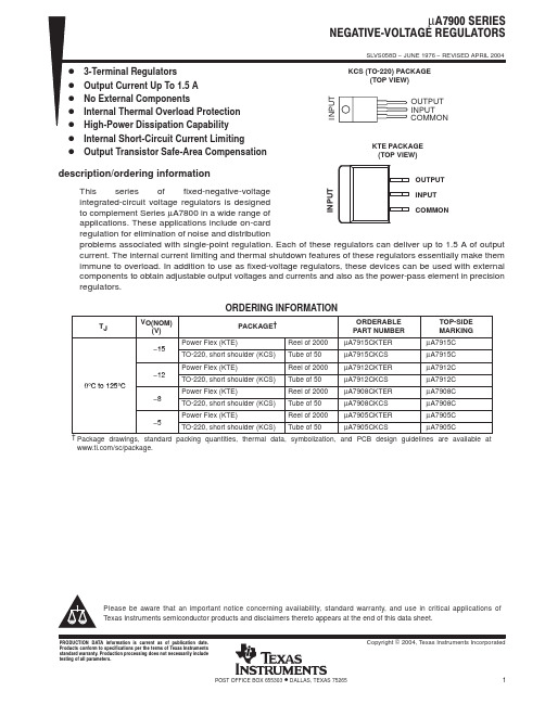
0°C to 125°C
Power Flex (KTE)
Reel of 2000 µA7912CKTER
−12 TO-220, short shoulder (KCS) Tube of 50
µA7912CKCS
Power Flex (KTE)
Reel of 2000 µA7908CKTER
−8 TO-220, short shoulder (KCS) Tube of 50
components to obtain adjustable output voltages and currents and also as the power-pass element in precision regulators.
ORDERING INFORMATION
TJ
VO(NOM) (V)
0
MAX −25 −25 −30 −30 1.5 125
UNIT
V
A °C
2
• POST OFFICE BOX 655303 DALLAS, TEXAS 75265
元器件交易网
µA7900 SERIES NEGATIVEĆVOLTAGE REGULATORS
ą
SLVS058D − JUNE 1976 − REVISED APRIL 2004
electrical characteristics at specified virtual junction temperature, VI = −10 V, IO = 500 mA (unless otherwise noted)
PARAMETER
TEST CONDITIONS
TJ†
µA7905C UNITS
LM7912CT中文资料
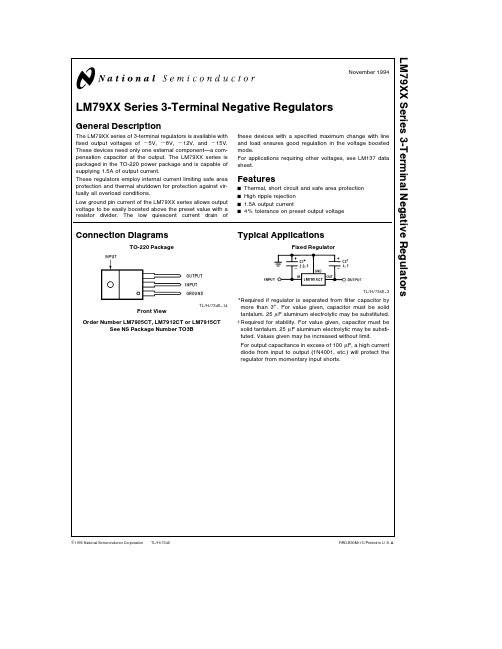
TL H 7340LM79XX Series 3-Terminal Negative RegulatorsNovember1994LM79XX Series3-Terminal Negative RegulatorsGeneral DescriptionThe LM79XX series of3-terminal regulators is available withfixed output voltages of b5V b8V b12V and b15VThese devices need only one external component a com-pensation capacitor at the output The LM79XX series ispackaged in the TO-220power package and is capable ofsupplying1 5A of output currentThese regulators employ internal current limiting safe areaprotection and thermal shutdown for protection against vir-tually all overload conditionsLow ground pin current of the LM79XX series allows outputvoltage to be easily boosted above the preset value with aresistor divider The low quiescent current drain ofthese devices with a specified maximum change with lineand load ensures good regulation in the voltage boostedmodeFor applications requiring other voltages see LM137datasheetFeaturesY Thermal short circuit and safe area protectionY High ripple rejectionY1 5A output currentY4%tolerance on preset output voltage Connection DiagramsTO-220PackageTL H 7340–14Front ViewOrder Number LM7905CT LM7912CT or LM7915CTSee NS Package Number TO3BTypical ApplicationsFixed RegulatorTL H 7340–3Required if regulator is separated from filter capacitor bymore than3 For value given capacitor must be solidtantalum 25m F aluminum electrolytic may be substitutedRequired for stability For value given capacitor must besolid tantalum 25m F aluminum electrolytic may be substi-tuted Values given may be increased without limitFor output capacitance in excess of100m F a high currentdiode from input to output(1N4001 etc )will protect theregulator from momentary input shortsC1995National Semiconductor Corporation RRD-B30M115 Printed in U S AAbsolute Maximum Ratings (Note 1)If Military Aerospace specified devices are required please contact the National Semiconductor Sales Office Distributors for availability and specifications Input Voltage (V o e b 5V)b 25V (V o e b 12V and b 15V)b 35VInput-Output Differential (V o e b 5V)25V (V o e b 12V and b 15V)30VPower Dissipation (Note 2)Internally LimitedOperating Junction Temperature Range 0 C to a 125 CStorage Temperature Rangeb 65 C to a 150 C Lead Temperature (Soldering 10sec )230 CElectrical Characteristics Conditions unless otherwise noted I OUT e 500mA C IN e 2 2m F C OUT e 1m F0 C s T J s a 125 C Power Dissipation s 1 5WPart Number LM7905CUnitsOutput Voltageb 5V Input Voltage (unless otherwise specified)b 10VSymbol Parameter ConditionsMinTypMaxV OOutput VoltageT J e 25 Cb 4 8b 5 0b 5 2V 5mA s I OUT s 1A b 4 75b 5 25V P s 15W(b 20s V IN s b 7)V D V OLine RegulationT J e 25 C (Note 3)850mV (b 25s V IN s b 7)V 215mV (b 12s V IN s b 8)V D V OLoad RegulationT J e 25 C (Note 3)5mA s I OUT s 1 5A15100mV 250mA s I OUT s 750mA 550mV I Q Quiescent Current T J e 25 C 12mA D I QQuiescent Current With Line0 5mA Change(b 25s V IN s b 7)V With Load 5mA s I OUT s 1A0 5mA V n Output Noise Voltage T A e 25 C 10Hz s f s 100Hz 125m V Ripple Rejection f e 120Hz5466dB (b 18s V IN s b 8)V Dropout VoltageT J e 25 C I OUT e 1A 1 1V I OMAXPeak Output Current T J e 25 C 2 2A Average Temperature I OUT e 5mA 0 4mV CCoefficient of 0C s T J s 100 COutput VoltageTypical Applications (Continued)Variable OutputTL H 7340–2Improves transient response and ripple rejection Do not increase beyond 50m F V OUT e V SETR1a R2R2JSelect R2as followsLM7905CT 300X LM7912CT 750X LM7915CT1k2Electrical Characteristics (Continued)Conditions unless otherwise noted I OUT e 500mA C IN e 2 2m F C OUT e 1m F 0 C s T J s a 125 C Power Dissipation e 1 5WPart Number LM7912CLM7915CUnitsOutput Voltageb 12V b 15V Input Voltage (unless otherwise specified)b 19Vb 23VSymbol Parameter ConditionsMinTyp Max Min TypMaxV OOutput VoltageT J e 25 Cb 11 5b 12 0b 12 5b 14 4b 15 0b 15 6V 5mA s I OUT s 1A b 11 4b 12 6b 14 25b 15 75V P s 15W(b 27s V IN s b 14 5)(b 30s V IN s b 17 5)V D V OLine RegulationT J e 25 C (Note 3)5805100mV (b 30s V IN s b 14 5)(b 30s V IN s b 17 5)V 330350mV (b 22s V IN s b 16)(b 26s V IN s b 20)V D V OLoad RegulationT J e 25 C (Note 3)5mA s I OUT s 1 5A1520015200mV 250mA s I OUT s 750mA 575575mV I Q Quiescent Current T J e 25 C 1 531 53mA D I QQuiescent Current With Line0 50 5mA Change(b 30s V IN s b 14 5)(b 30s V IN s b 17 5)V With Load 5mA s I OUT s 1A0 50 5mA V n Output Noise Voltage T A e 25 C 10Hz s f s 100Hz 300375m V Ripple Rejection f e 120Hz54705470dB (b 25s V IN s b 15)(b 30s V IN s b 17 5)V Dropout VoltageT J e 25 C I OUT e 1A 1 11 1V I OMAXPeak Output Current T J e 25 C 2 22 2A Average Temperature I OUT e 5mA b 0 8b 1 0mV CCoefficient of 0C s T J s 100 COutput VoltageNote 1 Absolute Maximum Ratings indicate limits beyond which damage to the device may occur Operating Ratings indicate conditions for which the device is intended to be functional but do not guarantee Specific Performance limits For guaranteed specifications and test conditions see the Electrical Characteristics Note 2 Refer to Typical Performance Characteristics and Design Considerations for detailsNote 3 Regulation is measured at a constant junction temperature by pulse testing with a low duty cycle Changes in output voltage due to heating effects must be taken into accountTypical Applications (Continued)Dual Trimmed SupplyTL H 7340–43Design ConsiderationsThe LM79XX fixed voltage regulator series has thermaloverload protection from excessive power dissipation inter-nal short circuit protection which limits the circuit’s maxi-mum current and output transistor safe-area compensationfor reducing the output current as the voltage across thepass transistor is increasedAlthough the internal power dissipation is limited the junc-tion temperature must be kept below the maximum speci-fied temperature(125 C)in order to meet data sheet specifi-cations To calculate the maximum junction temperature orheat sink required the following thermal resistance valuesshould be usedTyp Max Typ Max Package i JC i JC i JA i JAC W C W C W C WTO-2203 05 06040P D MAX e T J Max b T Ai JC a i CAorT J Max T Ai JAi CA e i CS a i SA(without heat sink) Solving for T JT J e T A a P D(i JC a i CA)ore T A a P D i JA(without heat sink)WhereT J e Junction TemperatureT A e Ambient TemperatureP D e Power Dissipationi JA e Junction-to-Ambient Thermal Resistancei JC e Junction-to-Case Thermal Resistancei CA e Case-to-Ambient Thermal Resistancei CS e Case-to-Heat Sink Thermal Resistancei SA e Heat Sink-to-Ambient Thermal ResistanceTypical Applications(Continued)Bypass capacitors are necessary for stable operation of theLM79XX series of regulators over the input voltage and out-put current ranges Output bypass capacitors will improvethe transient response by the regulatorThe bypass capacitors (2 2m F on the input 1 0m F on theoutput)should be ceramic or solid tantalum which havegood high frequency characteristics If aluminum electrolyt-ics are used their values should be10m F or larger Thebypass capacitors should be mounted with the shortestleads and if possible directly across the regulator termi-nalsHigh Stability1Amp RegulatorTL H 7340–5Load and line regulation k0 01%temperature stability s0 2%Determine Zener currentSolid tantalumSelect resistors to set output voltage 2ppm C tracking suggested4Typical Applications (Continued)Current SourceI OUT e 1mA a5V R1TL H 7340–7Light Controller Using Silicon Photo CellTL H 7340–8Lamp brightness increase until i I e i Q ( 1mA)a 5V R1Necessary only if raw supply filter capacitor is more than 2 from LM7905CT5Typical Applications(Continued)High-Sensitivity Light ControllerTL H 7340–9Lamp brightness increases until i i e5V R1(I i can be set as low as1m A)Necessary only if raw supply filter capacitor is more than2 from LM7905g15V 1Amp Tracking RegulatorsTL H 7340–1(b15)(a15)Load Regulation at D I L e1A40mV2mVOutput Ripple C IN e3000m F I L e1A100m Vrms100m VrmsTemperature Stability50mV50mVOutput Noise10Hz s f s10kHz150m Vrms150m VrmsResistor tolerance of R4and R5determine matching of(a)and(b)outputsNecessary only if raw supply filter capacitors are more than3 from regu-lators6Schematic Diagramsb 5VT L H 7340–127Schematic Diagrams (Continued)b 12V a n d b 15VT L H 7340–1389L M 79X X S e r i e s 3-T e r m i n a l N e g a t i v e R e g u l a t o r sPhysical Dimensions inches (millimeters)TO-220Outline Package (T)Order Number LM7905CT LM7912CT or LM7915CTNS Package Number T03BLIFE SUPPORT POLICYNATIONAL’S PRODUCTS ARE NOT AUTHORIZED FOR USE AS CRITICAL COMPONENTS IN LIFE SUPPORT DEVICES OR SYSTEMS WITHOUT THE EXPRESS WRITTEN APPROVAL OF THE PRESIDENT OF NATIONAL SEMICONDUCTOR CORPORATION As used herein 1 Life support devices or systems are devices or 2 A critical component is any component of a life systems which (a)are intended for surgical implant support device or system whose failure to perform can into the body or (b)support or sustain life and whose be reasonably expected to cause the failure of the life failure to perform when properly used in accordance support device or system or to affect its safety or with instructions for use provided in the labeling can effectivenessbe reasonably expected to result in a significant injury to the userNational Semiconductor National Semiconductor National Semiconductor National Semiconductor CorporationEuropeHong Kong LtdJapan Ltd1111West Bardin RoadFax (a 49)0-180-530858613th Floor Straight Block Tel 81-043-299-2309。
LM7912中文资料

-12
-12.5
V
IO = 5mA to1A,PO≤15W VI = -15.5V to -27V
-11.4
-12
-12.6
Line Regulation线性调整率(Note1)
ΔVO
TJ=+25℃
VI = -14.5V to -30V
-
12
240
mV
VI = -16V to -22V
-
6
(VI = -18V, IO = 500mA,0℃≤TJ≤+125℃, CI =2.2μF, CO =1μF, unless otherwise specified.)
Parameter参数
Symbol符号
Conditions条件
最小.
典型.
最大.
单位
Output Voltage输出电压
VO
TJ=+25℃
℃
图3输出电压图4负载调节率曲线图
图5电压差曲线图图6静态电流曲线图
图7短路电流曲线图
LM7912应用电路:
图8 LM7912典型应用电路
图9与78XX系列三端稳压构成的正负对称输出电压应用电路
ΔIQ
IO = 5mA to1A
-
0.05
0.5
mA
VI = -15V to -30V
-
0.1
1
Temperature Coefficient of VD温度系数
ΔVo/ΔT
IO = 5mA
-
-0.8
-
mV/℃
Output Noise Voltage输出噪声电压
VN
f = 10Hz to 100KHz TA =+25℃
proteus元器件名称中英文对照表(全)
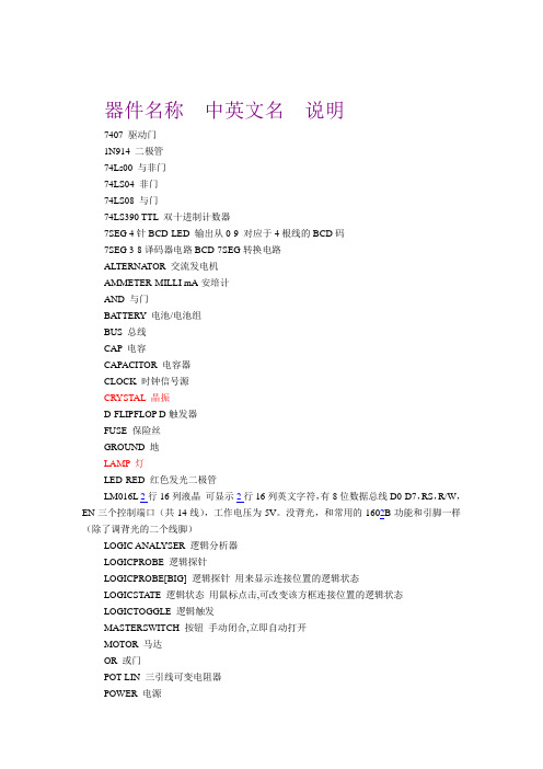
器件名称中英文名说明7407 驱动门1N914 二极管74Ls00 与非门74LS04 非门74LS08 与门74LS390 TTL 双十进制计数器7SEG 4针BCD-LED 输出从0-9 对应于4根线的BCD码7SEG 3-8译码器电路BCD-7SEG转换电路ALTERNATOR 交流发电机AMMETER-MILLI mA安培计AND 与门BA TTERY 电池/电池组BUS 总线CAP 电容CAPACITOR 电容器CLOCK 时钟信号源CRYSTAL 晶振D-FLIPFLOP D触发器FUSE 保险丝GROUND 地LAMP 灯LED-RED 红色发光二极管LM016L 2行16列液晶可显示2行16列英文字符,有8位数据总线D0-D7,RS,R/W,EN三个控制端口(共14线),工作电压为5V。
没背光,和常用的1602B功能和引脚一样(除了调背光的二个线脚)LOGIC ANAL YSER 逻辑分析器LOGICPROBE 逻辑探针LOGICPROBE[BIG] 逻辑探针用来显示连接位置的逻辑状态LOGICSTATE 逻辑状态用鼠标点击,可改变该方框连接位置的逻辑状态LOGICTOGGLE 逻辑触发MASTERSWITCH 按钮手动闭合,立即自动打开MOTOR 马达OR 或门POT-LIN 三引线可变电阻器POWER 电源RES 电阻RESISTOR 电阻器SWITCH 按钮手动按一下一个状态SW-SPDT-mom 二选通一按钮触发开关BUTTONVOLTMETER 伏特计VOLTMETER-MILLI mV伏特计VTERM 串行口终端Electromechanical 电机Inductors 变压器Laplace Primitives 拉普拉斯变换Memory IcsMicroprocessor IcsMiscellaneous 各种器件AERIAL-天线;ATAHDD;ATMEGA64;BATTERY;CELL;CRYSTAL-晶振;FUSE;METER-仪表;Modelling Primitives 各种仿真器件是典型的基本元器模拟,不表示具体型号,只用于仿真,没有PCBOptoelectronics 各种发光器件发光二极管,LED,液晶等等PLDs & FPGAsResistors 各种电阻Simulator Primitives 常用的器件Speakers & SoundersSwitches & Relays 开关,继电器,键盘BUTTON 触发开关Switching Devices 晶阊管Transistors 晶体管(三极管,场效应管)TTL 74 seriesTTL 74ALS seriesTTL 74AS seriesTTL 74F seriesTTL 74HC seriesTTL 74HCT seriesTTL 74LS seriesTTL 74S seriesAnalog Ics 模拟电路集成芯片Capacitors 电容集合CMOS 4000 seriesConnectors 排座,排插Data Converters ADC,DACDebugging Tools 调试工具7SEG 数码管ECL 10000 Series 各种常用集成电路1.电阻固定电阻:RES半导体电阻:RESSEMT电位计;POT变电阻;RV AR可调电阻;res1可变电阻pot2.电容定值无极性电容;CAP定值有极性电容;CAP半导体电容:CAPSEMI可调电容:CAPV AR3.电感:INDUCTOR4.二极管:DIODE.LIB发光二极管:LED5.三极管:NPN16.结型场效应管:JFET.lib7.MOS场效应管8.MES场效应管9.继电器:PELAY. LIB10.灯泡:LAMP11.运放:OPAMP12.数码管:7-SEG_DP (MISCELLANEOUS DEVICES.LIB)13.开关;sw_pb原理图常用库文件:Miscellaneous Devices.ddbDallas Microprocessor.ddbIntel Databooks.ddbProtel DOS Schematic Libraries.ddbPCB元件常用库:Advpcb.ddbGeneral IC.ddbMiscellaneous.ddb部分分立元件库元件名称及中英对照AND 与门ANTENNA 天线BA TTERY 直流电源BELL 铃,钟BVC 同轴电缆接插件BRIDEG 1 整流桥(二极管) BRIDEG 2整流桥(集成块) BUFFER 缓冲器BUZZER 蜂鸣器CAP 电容CAPACITOR 电容CAPACITOR POL 有极性电容CAPV AR 可调电容CIRCUIT BREAKER 熔断丝COAX 同轴电缆CON 插口CRYSTAL 晶体整荡器DB 并行插口DIODE 二极管DIODE SCHOTTKY 稳压二极管DIODE VARACTOR 变容二极管DPY_3-SEG 3段LEDDPY_7-SEG 7段LEDDPY_7-SEG_DP 7段LED(带小数点)ELECTRO电解电容FUSE 熔断器INDUCTOR 电感INDUCTOR IRON 带铁芯电感INDUCTOR3 可调电感JFET N N沟道场效应管JFET P P沟道场效应管LAMP 灯泡LAMP NEDN 起辉器LED 发光二极管METER 仪表MICROPHONE 麦克风MOSFET MOS管MOTOR AC 交流电机MOTOR SERVO 伺服电机NAND 与非门NOR 或非门NOT 非门NPN NPN三极管NPN-PHOTO 感光三极管OPAMP 运放OR 或门PHOTO 感光二极管PNP 三极管NPN DAR NPN三极管PNP DAR PNP三极管POT 滑线变阻器PELAY-DPDT 双刀双掷继电器RES1.2电阻RES3.4 可变电阻RESISTOR BRIDGE ? 桥式电阻RESPACK ? 电阻SCR 晶闸管PLUG ? 插头PLUG AC FEMALE 三相交流插头SOCKET ? 插座SOURCE CURRENT 电流源SOURCE VOLTAGE 电压源SPEAKER扬声器SW ? 开关SW-DPDY ? 双刀双掷开关SW-SPST ? 单刀单掷开关SW-PB 按钮THERMISTOR 电热调节器TRANS1 变压器TRANS2可调变压器TRIAC ? 三端双向可控硅TRIODE ? 三极真空管V ARISTOR 变阻器ZENER ? 齐纳二极管DPY_7-SEG_DP 数码管SW-PB 开关其他元件库Protel Dos Schematic 4000 Cmos .Lib (40.系列CMOS管集成块元件库)4013 D 触发器4027 JK 触发器Protel Dos Schematic Analog Digital.Lib(模拟数字式集成块元件库)AD系列DAC系列HD系列MC系列Protel Dos Schematic Comparator.Lib(比较放大器元件库)Protel Dos Shcematic Intel.Lib(INTEL公司生产的80系列CPU集成块元件库)Protel Dos Schematic Linear.lib(线性元件库)例555Protel Dos Schemattic Memory Devices.Lib(内存存储器元件库)Protel Dos Schematic SYnertek.Lib(SY系列集成块元件库)Protes Dos Schematic Motorlla.Lib(摩托罗拉公司生产的元件库)Protes Dos Schematic NEC.lib(NEC公司生产的集成块元件库)Protes Dos Schematic Operationel Amplifers.lib(运算放大器元件库)Protes Dos Schematic TTL.Lib(晶体管集成块元件库74系列)Protel Dos Schematic V oltage Regulator.lib(电压调整集成块元件库)Protes Dos Schematic Zilog.Lib(齐格格公司生产的Z80系列CPU集成块元件库)元件属性对话框中英文对照Lib ref 元件名称Footprint 器件封装Designator 元件称号Part 器件类别或标示值Schematic Tools 主工具栏Writing Tools 连线工具栏Drawing Tools 绘图工具栏稳压二极管ZENER DIODE肖特基二极管SCHOTTKY DIODE二极管DIODE变容二极管V ARIODE三极管TRANSISTOR电感INDUCTOR磁环EMIFIL电阻RESISTOR电容CAPACITY晶振CRYSTAL涤纶电容MYLAR CAP电解电容ELECT CAP瓷片电容CERAMIC CAP安规电容FILM CAPProtel 99 se的元件中英文PcbRe: [分享] protel99se 元件名系表--分立元件库中英文对照电阻AXIAL 无极性电容RAD 电解电容RB- 电位器VR 二极管DIODE 三极管TO 电源稳压块78和79系列TO-126H和TO-126V 场效应管和三极管一样整流桥D-44 D-37 D-46 单排多针插座CON SIP 双列直插元件DIP 晶振XTAL1电阻:RES1,RES2,RES3,RES4;封装属性为axial系列无极性电容:cap;封装属性为RAD-0.1到rad-0.4电解电容:electroi;封装属性为rb.2/.4到rb.5/1.0电位器:pot1,pot2;封装属性为vr-1到vr-5二极管:封装属性为diode-0.4(小功率)diode-0.7(大功率)三极管:常见的封装属性为to-18(普通三极管)to-22(大功率三极管)to-3(大功率达林顿管)电源稳压块有78和79系列;78系列如7805,7812,7820等79系列有7905,7912,7920等常见的封装属性有to126h和to126v整流桥:BRIDGE1,BRIDGE2: 封装属性为D系列(D-44,D-37,D-46)电阻:AXIAL0.3-AXIAL0.7其中0.4-0.7指电阻的长度,一般用AXIAL0.4 瓷片电容:RAD0.1-RAD0.3。
LM7912中文资料

LM7912中文资料(引脚图,电气特性参数,应用电路)
负12V,1A三端稳压器LM7912中文资料(引脚图,电气特性参数,应用电路) LM7912引脚图及外形图:
图1 LM7912外形引脚排列图管脚图
LM7912内部电路图:
图2 79XX内部电路图
LM7912电气特性参数:
Electrical Characteristics 电气特性(MC7912)
(VI = -18V, IO = 500mA, 0℃ ≤TJ ≤ +125℃, CI =μF, CO =1μF, unless otherwise specif ied.)
Parameter 参数Symbol 符号Value 数值单位
(for VO =5V to 18V)VI 35 V Input Voltage输入电压
(for VO =24V)VI 40 V
5 ℃/ Thermal Resistance Junction-Cases 热阻(结到壳) (TO-220)
RθJC
W
65 ℃/ Thermal Resistance Junction-Air热阻(结到空气) (TO-220)
RθJA
W Operating Temperature Range工作温度范围TOPR 0 ~ +125 ℃Storage Temperature Range储存温度范围TSTG -65 ~ +150 ℃
图3 输出电压图4 负载调节率曲线图
图5 电压差曲线图图6 静态电流曲线图
图7 短路电流曲线图
LM7912应用电路:
图8 LM7912典型应用电路
图9 与78XX系列三端稳压构成的正负对称输出电压应用电路。
UTCLM7912中文资料
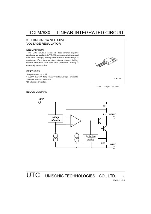
UTC LM79XXLINEAR INTEGRATED CIRCUITUTC UNISONIC TECHNOLOGIES CO., LTD.1QW-R101-007,B3 TERMINAL 1A NEGATIVE VOLTAGE REGULATORDESCRIPTIONThe UTC LM79XX series of three-terminal negativeregulators are available in TO-220 package and with several fixed output voltage, making them useful in a wide range of application. Each type employs internal current limiting, thermal shut-down and safe area protection, making it essentially indestructible.FEATURES*Output current up to 1A*-5V;-6V;-8V;-12V;-15V;-18V;-24V output voltage available *Thermal overload protection *Short circuit protection1:GND 2:Input 3:OutputBLOCK DIAGRAMUTC LM79XXLINEAR INTEGRATED CIRCUITUTC UNISONIC TECHNOLOGIES CO., LTD.2QW-R101-007,BABSOLUTE MAXIMUM RATINGS (Ta=25°C) PARAMETER SYMBOLVALUE UNITInput voltageVi -35 V Thermal resistance junction-airR θ JA 65 °C /W Thermal resistance junction-casesR θ JC 5 °C /W Operating Temperature Topr 0 ~ +125 °C Storage TemperatureTstg-65 ~ +150°CUTC7905 ELECTRICAL CHARACTERISTICS(Refer to test circuits, 0<Tj<125°C ,Io=500mA,Vi=-10V,Ci=33uF,Co=1uF, unless otherwise specified)PARAMETER SYMBOL TEST CONDITIONS MIN TYP MAX UNITTj=25°C-4.80-5.0 -5.20 V Output voltageVo 5.0mA<Io<1.0A,Po<15W Vi=-7V to -20V -4.75 -5.25VLine regulation ∆Vo Tj =25°C,Vi=-7V to -25V 10 100 mV Tj=25°C,Vi=-8V to -12VmV Load regulation ∆Vo Tj =25°C,Io=5.0mA to 1.5A10 100 mV Tj=25°C,Io=250mA to 750mA 3 50 mV Quiescent current I Q Tj=25°C3 6 mA Quiescent current change ∆I QIo=5mA to 1.0A 0.05 0.5 mA Vi=-7V to -25V 0.1 1.3 mA Output voltage drift ∆Vo/∆T Io =5mA -0.4 mV/°C Output noise voltage V N f=10hz to 100kHz,Ta=25°C 100 µV Ripple rejection RR f=120Hz, Vi=-8V to -18V 54 60 dB Dropout voltage Vo Io=1.0A,Tj=25°C 2 V Short circuit current Isc Vi=-35V,Ta=25°C 300 mA peak current Ipk Tj=25°C2.2 AUTC7906 ELECTRICAL CHARACTERISTICS(Refer to test circuits, 0<Tj<125°C ,Io=500mA,Vi=-11V,Ci=2.2uF,Co=1uF,unless otherwise specified)PARAMETER SYMBOL TEST CONDITIONS MIN TYP MAX UNITTj=25°C-5.76-6.00 -6.24 V Output voltageVo5.0mA<Io<1.0A,Po<15W Vi=-8V to -21V -5.70 -6.30 VLine regulation ∆Vo Tj =25°C,Vi=-8V to -25V10 120 mVTj=25°C,Vi=-9V to -13V5 60 mV Load regulation ∆Vo Tj =25°C,Io=5.0mA to 1.5A10 120 mVTj=25°C,Io=250mA to 750mA 3 60 mV Quiescent currentI Q Tj=25°C3 6 mA Quiescent current change ∆I QIo=5mA to 1.0A 0.5 mAVi=-8V to -25V 1.3 mAOutput voltage drift ∆Vo/∆T Io =5mA -0.5 mV/°COutput noise voltage V N f=10hz to 100kHz,Ta=25°C 130 µV Ripple rejection RR f=120Hz, Vi=-9V to -19V 54 60 dB Dropout voltage Vo Io=1.0A,Tj=25°C 2 V Short circuit current Isc Vi=-35V,Ta=25°C 300 mA peak currentIpk Tj=25°C2.2 AUTC LM79XX LINEAR INTEGRATED CIRCUITUTC UNISONIC TECHNOLOGIES CO., LTD.3QW-R101-007,BUTC7908 ELECTRICAL CHARACTERISTICS(Refer to test circuits, 0<Tj<125°C ,Io=500mA,Vi=-14V,Ci=2.2uF,Co=1uF,unless otherwise specified)PARAMETER SYMBOL TEST CONDITIONS MIN TYP MAX UNITTj=25°C-7.68-8.0 -8.32 V Output voltageVo5.0mA<Io<1.0A,Po<15W Vi=-10.5V to -23V -7.60 -8.40 VLine regulation ∆Vo Tj =25°C,Vi=-10.5V to -25V 10 100 mV Tj=25°C,Vi=-11.5V to -17V5 80 mV Load regulation ∆Vo Tj =25°C,Io=5.0mA to 1.5A12 160 mV Tj=25°C,Io=250mA to 750mA4 80 mV Quiescent current I Q Tj=25°C3 6 mA Quiescent current change ∆I QIo=5mA to 1.0A 0.05 0.5 mA Vi=-11.5V to -25V 0.1 1.0 mA Output voltage drift ∆Vo/∆T Io =5mA -0.6 mV/°C Output noise voltage V N f=10hz to 100kHz,Ta=25°C 175 µV Ripple rejection RR f=120Hz, Vi=-11.5V to -21.5V 54 60 dB Dropout voltage Vo Io=1.0A,Tj=25°C 2 V Short citcuit current Isc Vi=-35V,Ta=25°C 300 mA peak current Ipk Tj=25°C2.2 AUTC7912 ELECTRICAL CHARACTERISTICS(Refer to test circuits, 0<Tj<125°C ,Io=500mA,Vi=-18V,Ci=2.2uF,Co=1uF,unless otherwise specified)PARAMETER SYMBOL TEST CONDITIONS MIN TYP MAX UNITTj=25°C-11.52-12.0 -12.48 V Output voltageVo5.0mA<Io<1.0A,Po<15W Vi=-14.5V to -27V -11.40 -12.60 V Line regulation ∆Vo Tj =25°C,Vi=-14.5V to -30V12 240 mVTj=25°C,Vi=-16V to -22V6 120 mV Load regulation ∆Vo Tj =25°C,Io=5.0mA to 1.5A12 240 mVTj=25°C,Io=250mA to 750mA 4 120 mV Quiescent currentI Q Tj=25°C3 6 mA Quiescent current change ∆I QIo=5mA to 1.0A 0.05 0.5 mAVi=-14.5V to -30V 0.1 1.0 mAOutput voltage drift ∆Vo/∆T Io =5mA -0.8 mV/°COutput noise voltage V N f=10hz to 100kHz,Ta=25°C 200 µV Ripple rejection RR f=120Hz, Vi=-15V to -25V 54 60 dB Dropout voltage Vo Io=1.0A,Tj=25°C 2 V Short circuit current Isc Vi=-35V,Ta=25°C 300 mA peak currentIpk Tj=25°C2.2 AUTC LM79XX LINEAR INTEGRATED CIRCUITUTC UNISONIC TECHNOLOGIES CO., LTD.4QW-R101-007,BUTC7915 ELECTRICAL CHARACTERISTICS(Refer to test circuits, 0<Tj<125°C , Io=500mA,Vi=-23V,Ci=2.2uF,Co=1uF,unless otherwise specified)PARAMETER SYMBOL TEST CONDITIONS MIN TYP MAX UNITTj=25°C-14.40-15.0 -15.60 V Output voltageVo5.0mA<Io<1.0A,Po<15W Vi=-17.5V to -30V -14.25 -15.75 VLine regulation ∆Vo Tj =25°C,Vi=-17.5V to -30V 12 300 mV Tj=25°C,Vi=-20V to -26V6 150 mV Load regulation ∆Vo Tj =25°C,Io=5.0mA to 1.5A 12 300 mV Tj=25°C,Io=250mA to 750mA 4 150 mV Quiescent current I Q Tj=25°C3 6 mA Quiescent current change ∆I QIo=5mA to 1.0A 0.05 0.5 mA Vi=-17.5V to -30.5V 0.1 1.0 mA Output voltage drift ∆Vo/∆T Io =5mA -0.9 mV/°C Output noise voltage V N f=10hz to 100kHz,Ta=25°C 250 µV Ripple rejection RR f=120Hz, Vi=-18.5V to -28.5V 54 60 dB Dropout voltage Vo Io=1.0A,Tj=25°C 2 V Short circuit current Isc Vi=-35V,Ta=25°C 300 mA peak current Ipk Tj=25°C2.2 AUTC7918 ELECTRICAL CHARACTERISTICS(Refer to test circuits, 0<Tj<125°C ,Io=500mA,Vi=-27V,Ci=2.2uF,Co=1uF,unless otherwise specified)PARAMETER SYMBOL TEST CONDITIONS MIN TYP MAX UNITTj=25°C-17.28-18.0 -18.72 V Output voltageVo5.0mA<Io<1.0A,Po<15W Vi=-21V to -33V -17.10 -18.90 V Line regulation ∆Vo Tj =25°C,Vi=-21V to -33V15 360 mVTj=25°C,Vi=-24V to -30V8 180 mV Load regulation ∆Vo Tj =25°C,Io=5.0mA to 1.5A15 360 mVTj=25°C,Io=250mA to 750mA 5.0 180 mV Quiescent currentI Q Tj=25°C3 6 mA Quiescent current change ∆I QIo=5mA to 1.0A 0.5 mAVi=-21V to -32V 1.0 mAOutput voltage drift ∆Vo/∆T Io =5mA -1 mV/°COutput noise voltage V N f=10hz to 100kHz,Ta=25°C 300 µV Ripple rejection RR f=120Hz, Vi=-22V to -32V 54 60 dB Dropout voltage Vo Io=1.0A,Tj=25°C 2 V Short circuit current Isc Vi=-35V,Ta=25°C 300 mA peak currentIpk Tj=25°C2.2 AUTC LM79XX LINEAR INTEGRATED CIRCUITUTC UNISONIC TECHNOLOGIES CO., LTD.5QW-R101-007,BUTC7924 ELECTRICAL CHARACTERISTICS(Refer to test circuits, 0<Tj<125°C ,Io=500mA,Vi=-33V,Ci=2.2uF,Co=1uF,unless otherwise specified)PARAMETER SYMBOL TEST CONDITIONS MIN TYP MAX UNITTj=25°C-23.04-24 -24.96 V Output voltageVo5.0mA<Io<1.0A,Po<15W Vi=-27V to -38V -22.80 -25.20 VLine regulation ∆Vo Tj 25°C,Vi=-27V to -38V15 480mVTj=25°C,Vi=-30V to -36V8 240 mV Load regulation ∆Vo Tj 25°C,Io=5.0mA to 1.5A15 480 mVTj=25°C,Io=250mA to 750mA 5.0 240 mV Quiescent currentI Q Tj=25°C3 6 mA Quiescent current change ∆I QIo=5mA to 1.0A 0.5 mAVi=-27V to -38V 1.0 mAOutput voltage drift ∆Vo/∆T Io =5mA -1 mV/°COutput noise voltage V N f=10hz to 100kHz,Ta=25°C 400 µV Ripple rejection RR f=120Hz, Vi=-28V to -38V 54 60 dB Dropout voltage Vo Io=1.0A,Tj=25°C 2 V Short circuit current Isc Vi=-35V,Ta=25°C 300 mA peak currentIpk Tj=25°C2.2 AAPPLICATION CIRCUITSFig.1 Fixed output regulatorFig.2 Split power supply(+-15V,1A)UTC LM79XX LINEAR INTEGRATED CIRCUITFig.3 Circuit for increasing output voltageUTC UNISONIC TECHNOLOGIES CO., LTD. 6QW-R101-007,B。
霍尼韦尔氢气纯度仪说明书模板
目录1.前言………………………………………………………………………………2 1.1概述……………………………………………………………….........2 1.2传感单元 (2)1.37866数字控制器 (3)1.4操作原理 (4)2.技术参数和选型 (6)2.1技术参数……………………………………………………………………62.2选型 (8)3.安装……………………………………………………………………….........9 3.1传感单元要求条件和定位 (9)3.2安装传感单元 (9)3.3管路连接 (9)3.4传感单元与数字控制器接线 (10)4.设置模式………………………………………………………………………11 4.1概述………………………………………………………………………11 4.2结构概述……………………………………………………………………...11 4.3单元设置组群 (11)4.4报警设置组群 (12)4.5M o d B U S通讯设置组群 (12)4.6校准组群………………………………………………………………………13 4.7状态组群………………………………………………………………………13 5.校准……………………………………………………………………………14 5.1概述……………………………………………………………………...14 5.2传感单元校准 (14)5.37866分析仪输入校准 (14)5.4模拟输出校准 (15)5.7安全锁定……………………………………………………………………...16 5.8设置报警极限 (17)6.操作………………………………………………………………………………18 6.1启动………………………………………………………………………18 7.排除故障…………………………………………………………………………19 7.1概述……………………………………………………………………...19 7.27866数字控制器检测 (20)附录 (21)1.前言1.1 概述美国HONEYWELL公司7866氢气纯度分析仪由三个基本部件组成: 传感单元( 变送器) , 控制单元( 接收器) ( 图1-1) 和电源。
S7912PI资料
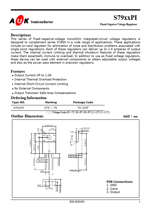
Ordering Information
Type NO. S79xxPI Marking S79□□PI Package Code TO-220F
□□:Voltage Code (05:-5V, 08:-8V, 09:-9V,12:-12V,15:-15V)
Outline Dimensions
unit :
IOUT=5mA ~ 1A VIN=-14.5V ~ -27V, VIN=-14.5V ~ -30V VIN=-16.0V ~ -22V IOUT=5mA ~ 1.0A IOUT=250mA ~ 750mA PD≤ 15W
S7912PI Min.
-11.5 -11.4 -
Typ.
-12.0 -12.0 5 3 15 5 2.0 0.04 0.08 300 60 2.0 -0.8 2.1
Ta=25°C
Symbol
VIN PD PD TJ TSTG
Ratings
-35 20.8 2.0 -30 ~ 125 -55 ~ 150
Unit
V W W °C °C
Electrical Characteristics
(TJ = 0 to 125℃, Vin= -10V, Iout=500mA, unless otherwise specified.)
Tj =25℃ Tj =25℃
mV
Quiescent Current Quiescent Current Change
VIN = -14.5V ~ -30V IOUT = 5mA ~ 1A
Output Noise Voltage Ripple Rejection Ratio Dropout Voltage Temperature coefficient output Voltage Drift Peak Output Current
NAPA 791-7200A 产品说明书与零件清单

NAPA PROFESSIONAL LIFTING EQUIPMENT WARRANTY STATEMENTWarranty Handling Procedures & GuidelinesBalkamp/NAPA Professional Lifting EquipmentBalkamp warrants that all jacks and service related equipment will be free from defects in material and workmanship for a period of 2 years following the original date of purchase. This warranty is extended to the original retail purchaser only. If any jack or service-related item proves to be defective during this period, it will be replaced or repaired, at our option, without charge. This warranty does not apply to damage from accident, overload, misuse or abuse, nor does it apply to any equipment which has been altered or used with special attachments other than those recommended. This warranty does not cover repairs made by anyone who is not a BALKAMP/NAPA Professional Lifting Equipment Authorized Repair Center.The following items possess an over-the-counter exchange warranty for 2 years. This allegedly defective product must be returned, accompanied by a receipt showing proof-of-purchase to Balkamp, via the NAPA AUTO PARTS store.•Bottle Jacks: 791-2230, 791-2240, 791-2260, 791-2270, 791-2280, 770-2290,791-2330, 791-6010, 791-6020•Floor Jacks: 791-6420, 791-6425•Stands: 791-5050, 791-5160, 791-5220, 791-5240, 791-5250•Engine Stand: 791-5070•Transmission Adapter: 791-7130All other jacks or service-related equipment will be replaced or repaired at Balkamp’s option during the 2 year warranty period.During the 2 year warranty period, all alleged defective product and/or part must be shipped, freight prepaid, along with proof of date-of-purchase, to your nearest Balkamp/NAPA Professional Lifting Equipment Authorized Warranty Center. Be certain to include your name, address and phone number along with proof-of-purchase information, and a brief description of the alleged defect. The product will be returned to the customer, freight prepaid.Many alleged defectives may simply be handled by calling your nearest Service Center for parts. See next page for a listing of authorized warranty service centers.In no event shall Balkamp be liable for incidental or consequential damages. The liability on any claim for lossor damage arising out of the sale, resale or use of a jack or related service equipment, shall in no event exceedthe purchase price. SOME STATES DO NOT ALLOW THE EXCLUSION OR LIMITATION OF INCIDENTAL OR CONSEQUENTIAL DAMAGES, SO THE ABOVE LIMITATION MAY NOT APPLY TO YOU.THIS WARRANTY IS THE SOLE AND EXCLUSIVE WARRANTY PROVIDED IN CONNECTION WITH THE SALE OF BALKAMP/NAPA PROFESSIONAL LIFTING EQUIPMENT. ALL OTHER WARRANTIES, INCLUDING ANY IMPLIED WARRANTIES OF MERCHANTABILITY OR FITNESS FOR A PARTICULAR PURPOSE, ARE EXCLUDED.THIS WARRANTY GIVES YOU SPECIFIC LEGAL RIGHTS AND YOU MA Y ALSO HAVE OTHER RIGHTS WHICH VARY FROM STATE TO STATE.。
BL0972 交 直流电能计量芯片 数据手册 V1.0说明书

BL0972交/直流电能计量芯片数据手册V1.0目录1、产品简述 (5)2、基本特征 (6)2.1主要特点 (6)2.2系统框图 (7)2.3管脚排列(TSSOP20) (7)2.4性能指标 (8)2.4.1电参数性能指标 (8)2.4.2极限范围 (9)3、工作原理 (10)3.1电流电压波形产生原理 (10)3.1.1PGA增益调整 (10)3.1.2相位补偿 (11)3.1.3通道偏置校正 (11)3.1.4通道增益校正 (12)3.1.5电流电压波形输出 (12)3.2有功功率计算原理 (13)3.2.1有功波形的选择 (14)3.2.2有功功率输出 (14)3.2.3有功功率校准 (14)3.2.4有功功率的防潜动 (15)3.2.5有功功率小信号补偿 (15)3.3有功能量计量原理 (16)3.3.1有功能量输出 (16)3.3.2有功能量输出选择 (16)3.3.3有功能量输出比例 (17)3.4电流电压有效值计算原理 (17)3.4.1有效值输出 (18)3.4.2有效值输入信号的设置 (18)3.4.3有效值刷新率的设置 (18)3.4.4电流电压有效值校准 (19)3.4.5有效值的防潜动 (19)3.5快速有效值检测原理 (20)3.5.1快速有效值输出 (20)3.5.2快速有效值输入选择 (21)3.5.3快速有效值累计时间和阈值 (21)3.5.4电网频率选择 (21)3.5.5快速有效值超限数据保存 (22)3.5.6过流指示 (22)3.5.7继电器控制 (22)3.6温度计量 (23)3.7.1线周期计量 (23)3.7.2线频率计量 (23)3.7.3相角计算 (24)3.7.4功率符号位 (24)3.8故障检测 (25)3.8.1过零检测 (25)3.8.2峰值超限 (25)3.8.3线电压跌落 (26)3.8.4过零超时 (27)3.8.5电源供电指示 (28)4、内部寄存器 (30)4.1电参量寄存器(只读) (30)4.2校表寄存器(外部写) (30)4.3OTP寄存器 (32)4.4模式寄存器 (33)4.4.1 MODE1寄存器 (33)4.4.2 MODE2寄存器 (33)4.4.3 MODE3寄存器 (34)4.5中断状态寄存器 (34)4.5.1 STATUS1寄存器 (34)4.5.2 STATUS3寄存器 (34)4.6校表寄存器详细说明 (34)4.6.1 通道PGA增益调整寄存器 (34)4.6.2 相位校正寄存器 (35)4.6.3 有效值增益调整寄存器 (35)4.6.4 有效值偏置校正寄存器 (36)4.6.5 有功小信号补偿寄存器 (36)4.6.7 防潜动阈值寄存器 (36)4.6.8 快速有效值相关设置寄存器 (37)4.6.9 过流报警及控制 (38)4.6.11 能量读后清零设置寄存器 (39)4.6.12 用户写保护设置寄存器 (39)4.6.13 软复位寄存器 (39)4.6.14 通道增益调整寄存器 (40)4.6.15 通道偏置调整寄存器 (40)4.6.16 有功功率增益调整寄存器 (40)4.6.17 有功功率偏置调整寄存器 (41)4.6.20 CF缩放比例寄存器 (41)4.7电参数寄存器详细说明 (42)4.7.1 波形寄存器 (42)4.7.2 有效值寄存器 (42)4.7.3 快速有效值寄存器 (42)4.7.7 电能脉冲计数寄存器 (43)4.7.8 波形夹角寄存器 (44)4.7.9 快速有效值保持寄存器 (44)4.7.11 线电压频率寄存器 (44)5、SPI通讯接口 (45)5.1概述 (45)5.2工作模式 (45)5.3帧结构 (45)5.4读出操作时序 (46)5.5写入操作时序 (47)5.6SPI接口的容错机制 (48)6、典型应用图 (49)7、封装信息 (50)1、产品简述BL0972是一颗内置时钟的单相交/直流电能计量芯片。
LM7912中文资料

Electrical Characteristics 电气特性 (MC7912)
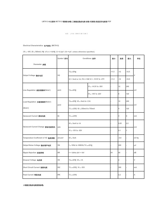
(VI = -18V, IO = 500mA, 0℃ ≤TJ ≤ +125℃, CI =2.2μF, CO =1μF, unless otherwise specified.)
Parameter 参数 Output Voltage 输出电压
TJ=+25℃ VI = -14.5V to -30V VI = -16V to -22V -
TJ=+25℃ IO = 5mA to 1.5A
-
TJ =+25 ℃ IO = 250mA to 750mA
12
240
mV
6
120
12
240
mV
4
120
Quiescent Current 静态电流
IQ
TJ =+25℃
TJ =+25℃, VI = -35V
-
300 -
mA
Peak Current 峰值电流
IPK
TJ =+25℃
-
2.2
-
A
三端稳压集成电路极限参数:
Parameter 参数
Input Voltage 输入电压
(for VO =5V to 18V) (for VO =24V)
Thermal Resistance Junction-Cases 热阻(结到壳) (TO-220)
电压
VN
f = 10Hz to 100KHz TA =+25℃
-
200 -
μV
Ripple Rejection 纹波抑制
RR
7912资料
Symbol符号
Conditions条件
最小.
典型.
最大.
单位
Output Voltage输出
-12.5
V
IO = 5mA to 1A,PO≤ 15W VI = -15.5V to -27V
-11.4
-12
-12.6
Line Regulation线性调整率(Note1)
-
4
120
Quiescent Current静态电流
IQ
TJ =+25℃
-
3
6
mA
Quiescent Current Change静态电流变化
ΔIQ
IO = 5mA to 1A
-
0.05
0.5
mA
VI = -15V to -30V
-
0.1
1
Temperature Coefficient of VD温度系数
VD
TJ=+25℃IO = 1A
-
2
-
V
Short Circuit Current短路电流
ISC
TJ =+25℃, VI = -35V
-
300
-
mA
Peak Current峰值电流
IPK
TJ =+25℃
-
2.2
-
A
三端稳压集成电路极限参数:
Parameter参数
Symbol符号
Value
单位
Input Voltage输入电压
(for VO =5V to 18V)
VI
35
V
(for VO =24V)
PC792H1AC1-12SN中文资料

60/40 Amp Automotive P lug-In / PCB Power RelayFEATURESMost popular automotive relay1 A and 1 C contact forms ava ilable60 Amps continuous carrying c apacityContact switching capacity up to 120 Amps Up to 125 degrees C operating temperature Five different case styles availa blePC792HMax. Switching Voltage Current Dependent; see curve page 21 Form A or 1 Form CCONTACT RATINGSCHARACTERISTICSOperate Time 7 ms. typical Release Time Insulation Resistance 2 ms. typical100 megohms min, at 500VDC, 50%RH Dielectric Strength 500 Vrms, 1 min. between coil and contacts Shock Resistance 20 g, 11ms, functional; 200 g, destructiveVibration Resistance Power Consumption 1.6 W approx.Ambient Temperature Range -40 to 125 degrees C operating, -40 to 155 stor age Weight35 grams approx.Sockets available from Picker C omponentsCONTACT DATAMaterialInitial Contact Resistance Service LifeMechanical ElectricalAgCdO (Silver Cadmium Oxide)100 milliohms max @ 0.1A, 6VDC 1 X 1072 X 105Operations OperationsNormally Open Contact FormMax Switching Current Break 60 AmpsMake 120 Amps 60 AmpsMax. Continuous Current Minimum Load0.5 A @ 12 VDCDrop Resistance 1 Meter height drop on concrete in final enclosu re Normally Closed Break 40 AmpsMake 45 Amps 40 AmpsDA 1.27 mm, 10 - 40 Hz; 40-70 Hz: 5 g; DA 0.5mm, 70-100 Hz; 100-500 Hz: 10 g.ORDERING INFORMATIONExample:PC792H Model-12Parallel Component-1C Nil: None; D: Diode; R: Resistor; N: N ickle Plated TerminalsCoil Voltage-C1-RNCase StyleC: Plug-In; P: PCB; C1: Plastic Bracket; C3: Shroud ed W/Metal Bkt S EnclosureC: Dust Cover, S: Sealed CaseContact Form1A, 1C or 1U (1 form A with 2 #87 Termin als)PC792HPC792HREFERENCE CURVEPower Load LimitCOIL DATACoil Voltage624Resistanceohms + 10%Must OperateVoltage Max.(VDC)Must Release Voltage Min.(VDC)Continuous Voltage Max.(VDC)22903307.214.31.22.420.539.1_ 3.60.610.112(17.9).705(8.4).331(16.9).665(8.0).3158787A308586(17.9).705(8.4).331(16.9).665(8.0).3158787A 308586(1.2 X 2.4).047 X .094All Holes3085Wiring Diagrams3085Form 1ASForm 1AForm 1CDimensions in Inches (millimet ers)Plug-In TypeBottom View PC Board LayoutTolerances +.010 unless otherwise notedNotes:Maximum make current refers to inrush of a lamp load In 85 degree C ambient reduce maximum coil volt age to 72%Plug-In Case (C) and PCB Case (P)(25.0).984(28.0)1.10(28.0)1.10(6.3).250(11.5).453(0.8).031PC792H PC792H(22.0).866(16.0).630(25.0).984(6.0).236(6.4).252 Dia.(28.0)1.10(28.0)1.10(4.2).165(28.0)1.10(28.0)1.10(16.0).630(25.0).984(15.0).591(6.0).236(5.3).210 Dia.(4.6).181(13.3).524(18.0).709(7.0).275.252 Dia.(6.4)(20.6).811(45.3)1.78(36.0)1.42(36.0)1.42(10.4).409Molded Plastic Bracket (C1)Bent Metal Bracket (C3)Metal Bracket (C2)Skirted Case with Metal Bracke t (C4)Skirted Case with Bent Metal B racket (C5)。
Fluke H12012 产品说明书
'DWD $FTXLVLWLRQ
Communication Products and Converters, Data Acquisition and Analysis Software, Data Loggers Plug-in Cards, Signal Conditioners, USB, RS232, RS485, Ehernet and Parallel Port Data Acquisition Systems, Wireless Transmitters and Receivers
A Range °C
• -20~1370
1 mv/F°
1 mv/C° -50~1300° -50~1300
T Range °F
U
Backlit LCD Data Hold
R Capacitance
-4~2498
-58~2372
•
•
•
•
•
•
•
•
25 µF 25 µF 25 µF
-58~2000
•
Q
E Frequency
Stick Type Thermometers and Transducers
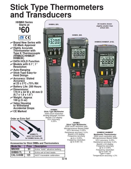
HHM60 Series Starts at
$60
HHM64, $69.
HHM63, $86.
All models shown slightly smaller than
actual size.
ߜ Brand New Series with
Price
$69
$102 $102 $86
$60
$60
$80
Resolution (Counts) 3200
hs7a-dmc7902原理_理论说明以及概述

hs7a-dmc7902原理理论说明以及概述1. 引言:1.1 概述:本文将对HS7A-DMC7902进行理论说明和概述。
HS7A-DMC7902是一种电子器件,具有多种应用和功能。
通过深入研究和分析,我们可以更好地了解HS7A-DMC7902的基本原理、工作原理以及它的应用范围等方面的知识。
1.2 文章结构:接下来的章节将逐步介绍HS7A-DMC7902的各个方面。
第二部分将详细解释HS7A-DMC7902的基本原理和DMC7902的工作原理,并探讨HS7A-DMC7902所适用的范围。
第三部分将介绍HS7A-DMC7902的技术参数,包括输入电压、输出电流范围、输出功率、效率指标以及控制方式和接口规格等信息。
第四部分将评估HS7A-DMC7902的优势与不足,包括对其优点和应用场景进行分析,以及提出改进措施讨论其缺点。
最后,在第五部分中,我们将总结结论,并展望HS7A-DMC7902未来可能的发展前景。
1.3 目的:本文旨在提供读者对HS7A-DMC7902的全面了解。
通过深入剖析其原理、技术参数以及优势与不足,读者将能够理解该电子器件的工作机制和应用范围,并对其性能进行评估。
此外,本文也将为HS7A-DMC7902未来的发展方向提供一些展望。
2. HS7A-DMC7902原理理论说明:2.1 HS7A-DMC7902的基本原理HS7A-DMC7902是一种特殊用途的电子设备,它采用了先进的控制电路和功率传输技术,用于实现高效能的功率转化。
该设备主要由两个核心部分组成:HS7A (High-Speed 7A)部分和DMC7902(Digital Motor Control 7902)部分。
HS7A部分是高速控制芯片,负责接收输入信号,并根据输入信号控制输出端口的电流和电压来实现准确的功率调节。
它具有高速响应能力和精确控制功能,可以快速准确地调整输出功率,适应不同场景需求。
DMC7902部分是数字电机控制芯片,利用先进的数字信号处理算法对输出端口传输的电流进行数字调节。
EH71270资料

TUNING VARACTORSelection GuidePAGE SURFACE MOUNT SILICON ABRUPT TUNING VARACTOR1-32HIGH Q SILICON ABRUPT JUNCTION TUNING VARACTOR-VBR = 30 V1-34 -VBR = 45 V1-35 SILICON HYPERABRUPT JUNCTION TUNING VARACTOR1-36 MICROWAVE SILICON HYPERABRUPT JUNCTION TUNING VARACTOR1-39 A tuning varactor is a P-N diode that acts as a voltage controlled capacitor. These devices perform the same function as the familiar, bulky, air dielectric stacked capacitors featured in traditional broadcast band receivers.DescriptionThis series of silicon tuning varactors have an epitaxial mesa design with a high temperature passivation. This technology is used to produce abrupt tuning varactor in SOT23 package. This family is designed for a low cost medium to high volume market that may be supplied in tape and reel for automated pick and place assembly on surface mount circuit boards.ApplicationsThe DH71000 series abrupt tuning varactor are offered in a large selection of capacitance range. They provide the highest Q factor (low reverse series resistance) available for a 30 volts silicon device.Typical applications include low noise narrow and moderate frequency bandwidth applications (VCO mainly) from HF to Microwave frequencies (up to 3 GHz). Other applications are voltage tuned filters, phase shifters, delay line, etc.NOTE : Variation of the junction capacitance versus reverse voltage follows this equation:C j (V r) C j (0 V)1 + V rV r : Reversevoltage φ: Built-in potential .7V for Siγ: .5 for abrupt tuning varactor[ ]SOT23 SURFACE MOUNT SILICON ABRUPT TUNING VARACTORγ=Electrical characteristics at T a = +25°CReverse breakdown voltage, Vb = @10 µA: 30 V min.T emperature ranges:Operating junction (T j): -55°C to +125°C Storage:-65°C to +150°C Packages(1) Other configuration available on request.How to order?DH71010-51T3Diode type Package Conditioninginformation51: single SOT23T3: 3000 pieces53: dual common tape & reelcathode SOT23T10: 10000 pieces54: dual common tape & reelanode SOT23blank: bulk60: single SOD32370: dual SOT143V BR 30VThis series of high Q epi-junction microwave tuning varactors (30 V) incorporates a passivated mesa technology. It is well suited for frequency tuning applications up to Ku band.Description(1)Custom cases available on requestT emperature ranges:(2)Closer capacitance tolerances available on request Operating junction (T j ):-55°C to +150°C (3)C = C + C Storage:-65°C to +175°CThis series of high Q epi-junction microwave tuning varactors (45 V) incorporates a passivated mesa technology. It is well suited for frequency tuning applications up to X band.DescriptionV BR 45VPLASTIC PACKAGE, SURFACE MOUNT HYPERABRUPT TUNING VARACTORDescriptionThis series of silicon tuning varactors consists of hyperabrupt epitaxial devices. They incorporate a passivated mesa technology. T his family is designed for a low cost medium to high volume market that may be supplied in tape and reel for automated pick and place assembly on surface mount circuit boards. ApplicationThe DH76000 and DH77000 series hyperabrupt tuning varactor are offered in a large selection of capacitance range. They provide the highest Q factor (low reverse series resistance). Typical applications include low noise narrow and moderate frequency bandwidth applications (VCO mainly) from HF to Microwave frequencies (up to 3 GHz). Other applications are voltage tuned filters, phase shifters, delay lines...20 Volt hyperabrupt junction varactorsCharacteristics @ T a=+25°C T emperature ranges:Reverse breakdown voltage, Vb = 20 V min. @ 10 µA Operating junction (Tj) : -55°C to +125°C Reverse Current, Ir = 200 nA @ 16 V Storage : -55°C to +150°C12 Volt hyperabrupt junction varactorsCharacteristics @ T a=+25°C T emperature ranges:Reverse breakdown voltage, Vb = 12 V min. @ 10 µA Operating junction (Tj) : -55°C to +125°C Reverse Current, Ir = 200 nA @ 8 V Storage : -55°C to +150°CT ypical junction capacitance versus reverse voltageVR (V)V (V)C j (p F )Packages(1) Other configuration available on request.How to order?DH76150-51T3Diode type Package Conditioninginformation51: single SOT23T3: 3000 pieces53: dual common tape & reelcathode SOT23T10: 10000 pieces54: dual common tape & reelanode SOT23blank: bulk60: single SOD32370: dual SOT143HIGH Q SILICON HYPERABRUPT JUNCTION TUNING VARACTORDescriptionThis series of silicon tuning varactors consists of hyperabrupt epitaxial devices.They incorporate a passivated mesa technology. Packaged or chip devices are available for linear electronic tuning from VHF up to Ku band.Characteristics @ T a = +25°CReverse breakdown voltage, Vb = @ 10 µA:20 V min.Reverse current, Ir @ 16 V: 200 nA(1)Custom cases available on requestT emperature ranges:Operating junction (T j ):-55°C to +150°C Storage:-65°C to +150°CT ypical junction capacitance reverse voltage。
hx712中文
HX712 Array TEL:(592) 252-9530 (P. R. China)AVIA SEMICONDUCTOREMAIL:典型特性测试条件:温度=25℃;AVDD=DVDD=REFP=5V,REFN=AGND;使用片内振荡器。
图二 输出噪声(增益=128,速率=10Hz) 图三 输出噪声(增益=128,速率=40Hz)图四 输出噪声(增益=256,速率=10Hz) 图五 输出噪声(增益=256,速率=40Hz)图六 零点漂移(增益=128,速率=10Hz) 图七 增益漂移(增益=128,速率=10Hz)图十一与HX712相关的参考PCB布图参考驱动程序(汇编)/*------------------------------------------------------------------- 在ASM中调用: LCALL ReadAD可以在C中调用: extern unsigned long ReadAD(void);..sbit ADDO = P1.5;sbit ADSK = P0.0;/*--------------------------------------------------OUT: R4, R5, R6, R7 R7=>LSB如果在C中调用,不能修改R4,R5,R6,R7。
---------------------------------------------------*/ReadAD:CLR ADSK //使能AD(PD_SCK置低)JB ADDO,$ //判断AD转换是否结束,若未结束则等待否则开始读取 MOV R4, #24ShiftOut:SETB ADSK //发送脉冲(PD_SCK置高)NOPCLR ADSK //PD_SCK置低MOV C,ADDO //读取数据(每次一位)XCH A,R7 //移入数据RLC AXCH A,R7XCH A,R6RLC AXCH A,R6XCH A,R5RLC AXCH A,R5DJNZ R4,ShiftOut //判断是否移入24BITSETB ADSK //发送第25个脉冲NOPCLR ADSKRETEND参考驱动程序(C)/*-------------------------------------------------------------------sbit ADDO = P1^5;sbit ADSK = P0^0;unsigned long ReadCount(void){unsigned long Count;unsigned char i;ADSK=0;Count=0;while(ADDO);for (i=0;i<24;i++){ADSK=1;Count=Count<<1;。
Agilent 1200 Infinity 系列产品介绍说明书

• Pump: New next generation inlet valves for better performance • Detectors: Next generation 1290 Infinity DAD technology • HiP Autosampler: leveraging of many parts of the 1290 Infinity
• 30 % Price Reduction by March 1st, attractive upfront contracts • Based on
– proven robustness – 2x higher than 1100 Series at introduction – Increased parts lifetime / longer maintenance intervalls – new design-for-supportability technology for faster maintenance,
1260 Infinity Quat./Iso LC 1220 Infinity LC
6
8
10 flow
Page 6
1260 Quaternary LC and 1220 Gradient LC
RRLC Performance for EVERY LAB!
10x productivity increase and improved data quality!
Conventional 4.6x150, 5µm Resolution peak 5 = 4.20 Run time 11 min
- 1、下载文档前请自行甄别文档内容的完整性,平台不提供额外的编辑、内容补充、找答案等附加服务。
- 2、"仅部分预览"的文档,不可在线预览部分如存在完整性等问题,可反馈申请退款(可完整预览的文档不适用该条件!)。
- 3、如文档侵犯您的权益,请联系客服反馈,我们会尽快为您处理(人工客服工作时间:9:00-18:30)。
Page No. : 1/4
H7912AE
H7912BE
3-TERMINAL NEGATIVE VOLTAGE REGULATOR
Description
regulation, eliminating the distribution problems associated with single point regulation; furthermore, having the same voltage options as the H7912_E positive standard series, they are particularly suited for split power supplies. If adequate heat sinking is provided, the H7912_E series can deliver an output current in excess of 1A although designed primarily as fixed voltage
Page No. : 2/4
Electrical Characteristics
Vin=-19V, Io=500mA, Cin=2.2uF, Cout=1uF, 0°C ≤Tj ≤125°C (unless otherwise noted)
H7912AE
Symbol Parameter Conditions
Min Typ Max Units
Tj=25°C
-11.64-12-12.36
Vo Output Voltage PD ≤15W, 5mA ≤Io ≤1A Vi=-14.5V to -27V
-11.58-12-12.42V
Tj=25°C, -14.5V ≤Vin ≤-30V --120∆Vo Line Regulation Tj=25°C, -16V ≤Vin ≤22V --30mV 5mA ≤Io ≤1.5A
--150∆Vo Load Regulation 250mA ≤Io ≤750mA --75mV IQ Quiescent Current Io ≤1A, Tj=25°C -38mA 5mA ≤Io ≤1A
--0.5∆IQ Quiescent Current Change
-14.5V ≤Vin ≤-30V -- 1.3mA ∆Vo / ∆T Output Voltage Drift Io=5mA
--0.4-mV/°C Vn Output Noise Voltage Ta=25°C, 10Hz to 100KHz -100-uV RR Ripple Rejection ∆Vi=10V, f=120Hz 5468-dB VD Dropout Voltage Tj=25°C, Io=1A -2-V Isc Short Circuit Current Tj=25°C, Vi=-35V - 2.2-A Ipk Peak Output Current
Tj=25°C
1.3
2.2
-A H7912BE Symbol Parameter Conditions
Min Typ Max Units Tj=25°C
-11.5-12-12.5
Vo Output Voltage PD ≤15W, 5mA ≤Io ≤1A
Vi=-14.5V to -27V
-11.4
-12-12.6V Tj=25°C, -14.5V ≤Vin ≤-30V
-10240∆Vo Line Regulation Tj=25°C, -16V ≤Vin ≤22V
-5120mV 5mA ≤Io ≤1.5A
--240∆Vo Load Regulation 250mA ≤Io ≤750mA
--120mV IQ Quiescent Current Io ≤1A, Tj=25°C
-38mA 5mA ≤Io ≤1A
--0.5∆IQ Quiescent Current Change
-14.5V ≤Vin ≤-30V -- 1.3mA ∆Vo / ∆T Output Voltage Drift Io=5mA --0.4-mV/°C Vn Output Noise Voltage Ta=25°C, 10Hz to 100KHz
-100-uV RR Ripple Rejection ∆Vi=10V, f=120Hz
5468-dB VD Dropout Voltage Tj=25°C, Io=1A
-2-V Isc Short Circuit Current Tj=25°C, Vi=-35V
- 2.2-A Ipk
Peak Output Current
Tj=25°C
1.3
2.2
-
A
Page No. : 3/4
Characteristics Curve
Page No. : 4/4
*: Typical
Inches Millimeters Inches Millimeters DIM Min.Max.Min.Max.DIM Min.Max.Min.Max.A 0.21970.2949 5.587.49I -*0.1508
-*3.83
B 0.32990.35048.388.90K 0.02950.03740.750.95
C 0.17320.185 4.40 4.70M 0.04490.0551 1.14 1.40
D 0.04530.0547 1.15 1.39N -*0.1000
-*2.54
E 0.01380.02360.350.60O 0.50000.561812.7014.27G 0.38030.40479.6610.28P
0.57010.624814.4815.87
H
-*0.6398-*16.25
Notes: 1.Dimension and tolerance based on our Spec. dated Sep. 07,1997.
2.Controlling dimension: millimeters.
3.Maximum lead thickness includes lead finish thickness, and minimum lead thickness is the minimum thickness of base material.
4.If there is any question with packing specification or packing method, please contact your local HSMC sales office.
Material:
• Lead: 42 Alloy ; solder plating
• Mold Compound: Epoxy resin family, flammability solid burning class: UL94V-0
Important Notice:
• All rights are reserved. Reproduction in whole or in part is prohibited without the prior written approval of HSMC.• HSMC reserves the right to make changes to its products without notice.
• HSMC semiconductor products are not warranted to be suitable for use in Life-Support Applications, or systems.
• HSMC assumes no liability for any consequence of customer product design, infringement of patents, or application assistance.
Head Office And Factory:
• Head Office (Hi-Sincerity Microelectronics Corp.): 10F.,No. 61, Sec. 2, Chung-Shan N. Rd. Taipei Taiwan R.O.C.Tel: 886-2-25212056 Fax: 886-2-25632712, 25368454
• Factory 1: No. 38, Kuang Fu S. Rd., Fu-Kou Hsin-Chu Industrial Park Hsin-Chu Taiwan. R.O.C Tel: 886-3-5983621~5 Fax: 886-3-5982931。
