RCCN Wiring Duct HVDRFZ 规格书
HVR 产品说明书

HVR产品使用说明书安装操作手册注意事项:请勿将重物至于本设备上;请勿让任何固体或液体,掉入或渗入设备内;请定期用刷子对电路板、接插件、机箱风机、机箱等进行除尘,在进行机体清洁工作前,请关闭电源并拔掉电源;请勿自行对本设备进行拆卸、维修或更换零件。
使用环境:请在0℃~40℃的温度下放置和使用本产品,避免阳光直射,或靠近热源;请勿将本设备安装在潮湿的环境;请勿将本设备暴露在多烟、多尘的环境;避免强烈的碰撞,请勿摔落机器;请保持本产品的水平安装,安装在稳定的场所,注意防止本产品坠落;请安装在通风良好的场所,切勿堵塞本产品的通风口;仅可在额定输入输出范围内使用。
目录第一章产品介绍 (5)1.1 产品概述 (5)1.2 产品主要功能 (5)第二章开箱检查和线缆连接 (7)2.1 开箱检查 (7)2.2 硬盘安装 (7)2.3 在机架中安装 (8)2.4 前面板 (8)2.5 后面板 (9)2.6 音视频输入输出连接 (9)2.6.1 视频输入的连接 (9)2.6.2 视频输出设备的选择和连接 (9)2.6.3 音频信号的输入 (10)2.6.4 音频输出 (10)2.7 报警输入输出连接 (10)2.7.1 报警输入端口说明 (11)2.7.2 报警输出端口说明 (12)2.7.3 报警输出端继电器参数 (12)2.8 球机连接 (12)第三章基本操作 (14)3.1 开机 (14)3.2 关机 (14)3.3 登录 (14)3.4 预览 (15)3.5 桌面快捷菜单 (15)3.5.1 主菜单 (16)3.5.2 录像回放 (16)3.5.3 录像控制 (18)3.5.4 报警输出 (18)3.5.5 云台控制 (19)3.5.6 图像颜色 (23)3.5.7 输出调节 (24)3.5.8 关闭系统 (24)3.5.9 页面切换 (25)第四章主菜单 (26)4.1 主菜单导航 (26)4.2 录像功能 (28)4.2.1 录像设置 (28)4.2.2 图片存储 (29)4.2.3录像回放 (30)4.2.4 录像备份 (30)4.3 报警功能 (31)4.3.1 移动侦测 (31)4.3.2 视频遮挡 (34)4.3.3 视频丢失 (35)4.3.4 报警输入 (36)4.3.5 报警输出 (37)4.3.6 异常处理 (37)4.4 系统设置 (38)4.4.1 普通设置 (38)4.4.2 编码设置 (39)4.4.3 网络设置 (41)4.4.4 网络服务 (41)4.4.5 输出模式 (48)4.4.6 云台设置/RS485设备 (49)4.4.7 串口设置 (51)4.4.8 轮巡设置 (51)4.4.9 通道管理 (52)4.5 管理工具 (55)4.5.1 硬盘管理 (55)4.5.2 用户管理 (56)4.5.3 在线用户 (58)4.5.4 输出调节 (58)4.5.5 自动维护 (58)4.5.6 恢复默认 (59)4.5.7 系统升级 (59)4.5.8 设备信息 (59)4.6 系统信息 (60)4.6.1 硬盘信息 (60)4.6.2 码流统计 (60)4.6.3 日志信息 (61)4.6.4 版本信息 (61)4.7 关闭系统 (62)第五章常见问题解答及使用维护 (63)5.1 常见问题解答 (63)5.2 使用维护 (69)附录1.遥控器操作 (70)附录2.鼠标操作 (71)附录3.硬盘的容量计算 (72)附录4.技术参数 (73)第一章产品介绍1.1 产品概述本设备是专为安防领域设计的一款优秀的数字监控产品。
塑料线槽规格
孔宽 Slot width
Q 8 8 8.5 8.5 8 8 8 8 8 8 8 8 8 8 8 8 8 8 6 8 8 8 8 8 8 8 8 8 8 8 8
齿宽 Finger width
P 10 10 12 12 12 10 10 10 10 10 10 10 12 12 12 12 12 12 10.5 12 12 12 12 12 12 12 12 12 12 12 12
RoHS REACH 94V-0
Special length come with MOQ request
推荐:灰色为常规库存产品,其它颜色有起订量要求。 Comment:gray is the common color, other color need more MOQ
样式:16mm-72mm宽 Style:Width from 16mm to 72mm
宽×高 High X width
W×H 16×16 25×16 15×20 20×20 40×20 15×25 20×25 25×25 30×25 40×25 50×25 15×30 20×30 25×30 30×30 40×30 50×30 60×30 22×33 33×33 20×35 35×35 50×35 20×40 25×40 35×40 40×40 60×40 80×40 100×40 120×40
型号 Item No.
白色White RAL9016 VDR1616FW VDR2516FW VDR1520FW VDR2020FW VDR4020FW VDR1525FW VDR2025FW VDR2525FW VDR3025FW VDR4025FW VDR5025FW VDR1530FW VDR2030FW VDR2530FW VDR3030FW VDR4030FW VDR5030FW VDR6030FW VDR2233FW VDR3333FW VDR2035FW VDR3535FW VDR5035FW VDR2040FW VDR2540FW VDR3540FW VDR4040FW VDR6040FW VDR8040FW VDR10040FW VDR12040FW
RCCN Wiring Duct SDRHF 规格书

Home / Products / Wiring Duct / RCCN Wiring Duct SDRHFRCCN Wiring Duct SDRHFHalogen Free Solid Wiring DuctWide slot/finger design provides greater sidewall rigidity and canbe used with a wide range of wire bundle sizes。
Certificates:UL CE:EN50085 RoHS,REACH。
Made of rigid Halogen free PCABSWork temperature:-40 °c to 110 °cUL94 Flammability Rating of V-0Provided with mounting holesAvailable color:gray.white.blue.black and other special colorsSpecial length come with MOQ requestHalogen Free Solid Wiring Duct Wiring DuctItem No.W*HWirecapability/2.0spPack/MGray White Blue BlackSDR1616/HF SDR1616W/HF SDR1616E/HF SDR1616B/HF16*163~10pcs300M *SDR2516/HF SDR2516W/HF SDR2516E/HF SDR2516B/HF25*165~15pcs240M *SDR4016/HF SDR4016W/HF SDR4016E/HF SDR4016B/HF40*1615~30pcs200M SDR1520/HF SDR1520W/HF SDR1520E/HF SDR1520B/HF15*208~12pcs260M SDR2020/HF SDR2020W/HF SDR2020E/HF SDR2020B/HF20*2010~20pcs240MSDR4020/HF SDR4020W/HF SDR4020E/HF SDR4020B/HF40*2020-30pcs140M SDR1525/HF SDR1525W/HF SDR1525E/HF SDR1525B/HF15*255~15pcs260M SDR2025/HF SDR2025W/HF SDR2025E/HF SDR2025B/HF20*255~15pcs200M SDR2525/HF SDR2525W/HF SDR2525E/HF SDR2525B/HF25*2510~25pcs200M SDR3025/HF SDR3025W/HF SDR3025E/HF SDR3025B/HF30*2512~28pcs160M *SDR4025/HF SDR4025W/HF SDR4025E/HF SDR4025B/HF40*2520~25pcs120M Specification*SDR5025/HF SDR5025W/HF SDR5025E/HF SDR5025B/HF50*2520~25pcs100M SDR1530/HF SDR1530W/HF SDR1530E/HF SDR1530B/HF15*308~15pcs200M SDR2030/HF SDR2030W/HF SDR2030E/HF SDR2030B/HF20*3025~35pcs180M SDR2530/HF SDR2530W/HF SDR2530E/HF SDR2530B/HF25*3025~35pcs160M SDR3030/HF SDR3030W/HF SDR3030E/HF SDR3030B/HF30*3025~35pcs140M SDR4030/HF SDR4030W/HF SDR4030E/HF SDR4030B/HF40*3030~40pcs100M GDR5030/HF GDR5030W/HF GDR5030E/HF GDR5030B/HF50*3040-50pcs80M GDR6030/HF GDR6030W/HF GDR6030E/HF GDR6030B/HF60*3050-60pcs60M SDR2233/HF SDR2233W/HF SDR2233E/HF SDR2233B/HF22*3315~25pcs180M SDR3333/HF SDR3333W/HF SDR3333E/HF SDR3333B/HF33*3330~40pcs160M SDR2035/HF SDR2035W/HF SDR2035E/HF SDR2035B/HF20*3530~40pcs100M SDR3535/HF SDR3535W/HF SDR3535E/HF SDR3535B/HF35*3535~45pcs112M SDR5035/HF SDR5035W/HF SDR5035E/HF SDR5035B/HF50*3540~60pcs88M *SDR2040/HF SDR2040W/HF SDR2040E/HF SDR2040B/HF20*4020~25pcs110M SDR2540/HF SDR2540W/HF SDR2540E/HF SDR2540B/HF25*4020~25pcs112M SDR3540/HF SDR3540W/HF SDR3540E/HF SDR3540B/HF35*4050-60pcs100M SDR4040/HF SDR4040W/HF SDR4040E/HF SDR4040B/HF40*4060~70pcs100M SDR6040/HF SDR6040W/HF SDR6040E/HF SDR6040B/HF60*40100~115pcs68M SDR8040/HF SDR8040W/HF SDR8040E/HF SDR8040B/HF80*40120~135pcs48M SDR10040/HF SDR10040W/HF SDR10040E/HF SDR10040B/HF100*40120~135pcs32M SDR12040/HF SDR12040W/HF SDR12040E/HF SDR12040B/HF120*40140-165pcs/ SDR2545/HF SDR2545W/HF SDR2545E/HF SDR2545B/HF25*4520~25pcs104M SDR3345/HF SDR3345W/HF SDR3345E/HF SDR3345B/HF33*4540~55pcs108M SDR4545/HF SDR4545W/HF SDR4545E/HF SDR4545B/HF45*4560~70pcs72M SDR6545/HF SDR6545W/HF SDR6545E/HF SDR6545B/HF65*45110~120pcs56M SDR2050/HF SDR2050W/HF SDR2050E/HF SDR2050B/HF20*5020~30pcs100M SDR2550/HF SDR2550W/HF SDR2550E/HF SDR2550B/HF25*5020~30pcs100M SDR3050/HF SDR3050W/HF SDR3050E/HF SDR3050B/HF30*5025~40pcs84M SDR3550/HF SDR3550W/HF SDR3550E/HF SDR3550B/HF35*5040~60pcs80M SDR4050/HF SDR4050W/HF SDR4050E/HF SDR4050B/HF40*5060~70pcs68M SDR4550/HF SDR4550W/HF SDR4550E/HF SDR4550B/HF45*5070~80pcs60M SDR5050/HF SDR5050W/HF SDR5050E/HF SDR5050B/HF50*5080~90pcs60M SDR5550/HF SDR5550W/HF SDR5550E/HF SDR5550B/HF55*5085~95pcs50M SDR6050/HF SDR6050W/HF SDR6050E/HF SDR6050B/HF60*50100~120pcs48M SDR7550/HF SDR7550W/HF SDR7550E/HF SDR7550B/HF75*50140~160pcs40M SDR8050/HF SDR8050W/HF SDR8050E/HF SDR8050B/HF80*50160~180pcs40M SDR10050/HF SDR10050W/HF SDR10050E/HF SDR10050B/HF100*50200~250pcs26M SDR12555/HF SDR12555W/HF SDR12555E/HF SDR12555B/HF125*55220~270pcs20M SDR2060/HF SDR2060W/HF SDR2060E/HF SDR2060B/HF20*605~45pcs100M SDR2560/HF SDR2560W/HF SDR2560E/HF SDR2560B/HF25*6040~50pcs100M SDR3060/HF SDR3060W/HF SDR3060E/HF SDR3060B/HF30*6060~80pcs80M *SDR3560/HF SDR3560W/HF SDR3560E/HF SDR3560B/HF35*6065~85pcs70M SDR4060/HF SDR4060W/HF SDR4060E/HF SDR4060B/HF40*60100~115pcs60M SDR4560/HF SDR4560W/HF SDR4560E/HF SDR4560B/HF45*60110~125pcs30M SDR5060/HF SDR5060W/HF SDR5060E/HF SDR5060B/HF50*60120~135pcs60M SDR6060/HF SDR6060W/HF SDR6060E/HF SDR6060B/HF60*60120~135pcs48M SDR8060/HF SDR8060W/HF SDR8060E/HF SDR8060B/HF80*60180~210pcs36M SDR10060/HF SDR10060W/HF SDR10060E/HF SDR10060B/HF100*60240~290pcs28M SDR11060/HF SDR11060W/HF SDR11060E/HF SDR11060B/HF110*60250~300pcs48M *SDR12060/HF SDR12060W/HF SDR12060E/HF SDR12060B/HF120*60260~320pcs48M SDE15060/HF SDE15060W/HF SDE15060E/HF SDE15060B/HF150*60300-360pcs16M SDR2565/HF SDR2565W/HF SDR2565E/HF SDR2565B/HF25*6540~50pcs88M SDR3365/HF SDR3365W/HF SDR3365E/HF SDR3365B/HF33*6540~70pcs80M SDR4565/HF SDR4565W/HF SDR4565E/HF SDR4565B/HF45*65110~120pcs52M SDR6565/HF SDR6565W/HF SDR6565E/HF SDR6565B/HF65*65180~200pcs44M SDR7265/HF SDR7265W/HF SDR7265E/HF SDR7265B/HF72*65190~210pcs40M2016/12/6RCCN Wiring Duct SDRHF - Wiring Duct - Products - Wiring duct,Cable Gland,Cable Tie,Terminals,RCCN SDR7265/HF SDR7265W/HF SDR7265E/HF SDR7265B/HF 72*65190~210pcs 40MSDR2575/HF SDR2575W/HF SDR2575E/HF SDR2575B/HF 25*75140-170pcs /SDR3575/HF SDR3575W/HF SDR3575E/HF SDR3575B/HF 35*75160-190pcs /SDR5075/HF SDR5075W/HF SDR5075E/HF SDR5075B/HF 50*75180~210pcs 32M SDR7575/HF SDR7575W/HF SDR7575E/HF SDR7575B/HF 75*75200~240pcs 24M SDR10075/HF SDR10075W/HF SDR10075E/HF SDR10075B/HF 100*75220~260pcs 24M SDR2580/HF SDR2580W/HF SDR2580E/HF SDR2580B/HF 25*80100~120pcs 72M SDR3080/HF SDR3080W/HF SDR3080E/HF SDR3080B/HF 30*80110~125pcs 56M SDR3580/HF SDR3580W/HF SDR3580E/HF SDR3580B/HF 35*80110~130pcs 56M SDR4080/HF SDR4080W/HF SDR4080E/HF SDR4080B/HF 40*80140~160pcs 48M SDR4580/HF SDR4580W/HF SDR4580E/HF SDR4580B/HF 45*80140~160pcs 40M SDR5080/HF SDR5080W/HF SDR5080E/HF SDR5080B/HF 50*80160~180pcs 40M SDR5580/HF SDR5580W/HF SDR5580E/HF SDR5580B/HF 55*80160~180pcs 32M SDR6080/HF SDR6080W/HF SDR6080E/HF SDR6080B/HF 60*80180~210pcs 32M SDR8080/HF SDR8080W/HF SDR8080E/HF SDR8080B/HF 80*80240~290pcs 24M SDR10080/HF SDR10080W/HF SDR10080E/HF SDR10080B/HF 100*80260~350pcs 24M SDR12080/HF SDR12080W/HF SDR12080E/HF SDR12080B/HF 120*80280~380pcs 16M SDR14080/HF SDR14080W/HF SDR14080E/HF SDR14080B/HF 140*80350~450pcs 16M SDR25100/HF SDR25100W/HF SDR25100E/HF SDR25100B/HF 25*100110~160pcs 60M SDR33100/HF SDR33100W/HF SDR33100E/HF SDR33100B/HF 33*100130~165pcs 44M SDR40100/HF SDR40100W/HF SDR40100E/HF SDR40100B/HF 40*100130~175pcs 40M SDR50100/HF SDR50100W/HF SDR50100E/HF SDR50100B/HF 50*100220~250pcs 40M SDR60100/HF SDR60100W/HF SDR60100E/HF SDR60100B/HF 60*100240~290pcs 32M SDR70100/HF SDR70100W/HF SDR70100E/HF SDR70100B/HF 70*100240~290pcs 32M SDR75100/HF SDR75100W/HF SDR75100E/HF SDR75100B/HF 75*100260~350pcs 24M SDR80100/HF SDR80100W/HF SDR80100E/HF SDR80100B/HF 80*100260~350pcs 24M SDR100100/HF SDR100100W/HF SDR100100E/HF SDR100100B/HF 100*100300~400pcs 24M SDR120100/HF SDR120100W/HF SDR120100E/HF SDR120100B/HF 120*100350~450pcs 16M SDR150100/HF SDR150100W/HF SDR150100E/HF SDR150100B/HF 150*100400~650pcs 16M SDR100130/HF SDR100130W/HF SDR100130E/HF SDR100130B/HF 100*130350~450pcs 16M *SDR200100/HF SDR200100W/HF SDR200100E/HF SDR200100B/HF 200*100600~800pcs 12M *SDR200150/HF *SDR200150W/HF *SDR200150E/HF *SDR200150B/HF 200*150900~1200pcs 10M Product ShowDow nloadRCCN Trunking UL certificate …RCCN Trunking CUL certificat…RCCN DIN5510 Wireway certi…Wireway REACH RCCN Wireway CE Certificate RCCN Sealed flame retardant…Catalogue-PDFPDF PDF PDF PDF PDFPDF2016/12/6RCCN Wiring Duct SDRHF - Wiring Duct - Products - Wiring duct,Cable Gland,Cable Tie,Terminals,RCCN More zProduct Wiring Duct >RCCN Sealed flame retardant…Catalogue-PDFRelated ProudctRCCN Wiring Duct SDRHF Halogen Free Solid Wiring Duct RCCN Wiring Duct VDR…Halogen Free Wiring Duct。
RCDF说明书中英文

RCDF系列油冷自卸式电磁除铁器Series RCDF Oil-cooling Self-cleaning Electromagnetic Iron Separator说明书Instruction for operation中国.制造Made in China一、用途Ⅰ、UseRCDF系列油冷自卸式电磁除铁器是一种用于清除散状非磁性物料中铁件的电磁设备。
一般安装于皮带输送机的头部或中部,通电产生的强大磁力将混杂在物料中的铁件吸出后由卸铁皮带抛出,达到清除的目的,并能有效地防止输送机皮带纵向划裂,保护破碎机、研磨机等正常工作,所以该系列除铁器广泛应用于电力、矿山、冶金、建材、选煤、化工等行业。
Series RCDC dry self-cleaning electromagnetic iron separator is a kind of magnetic equipment which is using in the iron removal from the non-magnetic material . It usually be installed in the front or center of the belt conveyor. The strong magnetic will absorb the pieces of iron which mixed with the materials and dished out by the iron-discharging belt, achieving the purpose of self-cleaning,and it can prevent the discharging belt Longitudinal crack,and ensure that the breaker and grinder work normly.So such series iron separator is widely used in electricity,mine,metallurgy,building material,coal dressing,Chemical industry and some other department.二、产品型号及其含义Model and meaning of the item自动卸铁油冷式Iron self-discharging and oil cooling电磁式Magnetic除铁器magnetic separator矿山机械类其它设备The other Equ. Of the mine machinery1三、使用条件Service condition3.1 海拔高度不超过2500米;The height above sea level should not above 2500meters;3.2 环境温度不高于+40℃及不低于-25℃;The surrounding temperature should not over 40℃,and below -20℃3.3 周围空气的湿度不大于90%(温度为25℃时);The relative humidity should not lager than 90%(25℃)3.4 无雨雪侵袭的地方;It can work in the place where is no rain and snow.3.5 在无爆炸危险的介质中,且介质中无足以腐蚀金属和破坏绝缘的气体与尘埃(包括导电尘埃)。
凯瑞兹GL4战术手电说明书
GL4说明书尺寸:55mm x100mm 材质:80g书纸Remote Switch深圳市龙岗区坂田街道龙景科技园E栋8楼518000 400-631-0169***********************深圳市凯瑞兹电子科技有限公司微信公众号静态电流战术鼠尾战术导轨夹战术灯Tactical rail clamp Tactical light ALLUMÉ/ÉTEINTb) ExtérieurOperación del interruptor remotoInterruptor principal: presione para encender y apagar (salida turbo)Interruptor de modo: mantén presionado para salida Turbo, suéltalo para apagar.Interruptor principalInterruptor de modoOpération:1) Commutateur de paramètres (la valeur par défaut est tactique)Depuis OFF, appuyez et maintenez enfoncé le commutateur MODE pendant 5 secondes. Appuyez sur le commutateur MAIN sans relâcher le commutateur MODE lorsque le voyant clignote en rouge/vert pour basculer entre les réglages2) Opération de paramétrage a) Tactique ALLUMÉ/ÉTEINTInterrupteur PRINCIPAL : appuyez pour allumer à HAUT, appuyez à nouveau pour éteindreCommutateur MODE : appuyez pour allumer le STROBED, maintenez-le enfoncé pendant 2 secondes pour LOCK STROBECommutateur MODE : appuyez pour changer la sortie Turbo->High->Medi-um->Low->Cycle. Appuyez et maintenez pendant 2 secondes pour entrer STROBEFernschalter:3.Um das Licht vom Adapter zu entfernen, drehen Sie den Verriegelungsknopf am Adapter leicht, um den Adapter zu lösen, und schieben Sie dann das Licht vom Adapter weg.1.Lösen und entfernen Sie dieEndkappe gegen den Uhrzeigersinn2.bringen Sie die Endkappe des Fernschalters an der Leuchte an und testen Sie die Funktion.1Método de instalación del producto1.Afloje los tornillos del adaptador de riel con la llave hexagonal incluida, alinee el adaptador con el riel del arma de fuego y apriete los tornillos para bloquear el adaptador en los rieles del arma de fuego.232.Inserte el conector de la luz en los rieles del adaptador hasta que se escuche un "clic", esto indica que la luz y el adaptador se han conectado de forma segura.3.Para quitar la luz del adaptador, gire ligeramente el botón de bloqueo en el adaptador para aflojar el adaptador, luego deslice la luz lejos del adaptador.Modes de sortie :。
无线充电器规格书

工作湿度:10% ~80%(没有水气凝结) Operating humidity:10% ~80% (No steam condensation)
存储温度:-20℃ ~70℃ Storage temperature:-20℃ ~70℃
3、 发射端线圈参数 Transmitting terminal coil’s parameter 3.1 线圈参数 The parameter of coil 3.2 发射端线圈尺寸 Transmitting terminal coil’s size 3.3 发射端 PCBA 外形 Transmitting terminal PCBA appearance
3.1 线圈参数 The parameter of coil
测试项目 Test item
(µH)
参数特征 Parameter characteristic 24.0
(mƸ)
75.0
建议误差值 Suggest error value
Ô10%
MAX 最大
3.2 发射端线圈尺寸 Transmitting terminal coil’s size
7、物料清单 BOM 7.1 接收端清单 Receiving end inventory
8、气候条件规格 Weather conditions standard 8.1 条件 Condition
8.2 跌落测试 Drop testing
1、 无线充电器发射端描述 Wireless charger transmitting terminal description
屏体技术参数-RCC瑞达恒

各子系统主设备的技术参数要求1、网络系统★服务承诺:提供原厂商针对本产品的3年保修服务承诺函原件防火墙上网行为管理核心交换机1.★配置单个控制引擎、冗余电源、冗余交换网板、千兆光口≥24个,;2.为了满足未来5-10年的业务发展需求,要求选用厂商高端数据中心系列;3.★整机总插槽≥14,2个主控槽位,4个交换网板槽位,8个业务槽位,并提供截图证明;4.★支持数据中心技术:支持虚拟化技术、大二层技术TRILL/SPB、FCoE技术、SDN;5.★背板容量≥32Tbps,包转发率≥7680Mpps(并提供截图证明);6.全面支持IPv6协议族,支持IPv6邻居发现、ICMPv6、Path MTU 发现、DHCPv6等IPv6特性;7.支持二、三层的MPLS VPN,可组建超大型的MPLS VPN核心网络,满足医疗行业专网VPN 用户的接入需求;8.★投标时需提供针对该项目的制造厂商3年原厂免费质保涵原件,加盖原厂公章汇聚交换机1.★交换容量:≥256Gbps,转发性能:≥192Mpps(若有不同指标,以较低为准);2.风扇固化,支持智能风扇调速3.性能指标:MAC地址表≥32K;4.★千兆电口≥24个,千兆/百兆自适应光口≥24个,万兆/千兆自适应光口≥8个;配置1个可热插拔电源AC220V5.★路由协议:支持IPv4静态路由、RIP V1/V2、OSPF、BGP;支持IPv6静态路由、RIPng、OSPFv3、BGP4+;支持IPv4和IPv6环境下的策略路由:支持IPv6手动隧道、6to4隧道和ISATAP隧道可靠性:支持VRRPv2/v3(虚拟路由冗余协议);支持环网保护技术,环网故障恢复时间不超过200ms;6.★管理和维护:支持SNMP V1/V2/V3、RMON、SSHV2;支持OAM(802.1AG,802.3AH)以太网运行、维护和管理标准7.★资质认证:要求提供信产部入网证和检验报告8.★投标时需提供针对该项目的制造厂商3年原厂免费质保涵原件,加盖原厂公章接入交换机1.★交换容量≥256Gbps2.★包转发率≥96Mpps3.★千兆电口×244.★百兆/千兆复用光口×45.★万兆光×46.★MAC地址表≥16K7.广播、组播风暴控制功能8.支持生成树SSTP、RSTP9.基于端口的VLAN 802.1Q VLAN,支持32个VLAN,1-4094任意划分10.每组最大4个,同时支持2组,动态LACP或者静态聚合11.支持FIFO、SP、WRR的优先级策略;支持基于DSCP、802.1P、TCP/UDP端口、物理端口的队列策略12.MAC地址绑定;基于TCP、UDP端口的L4报文过滤支持IGMP报文自动监测13.流量控制:半双工采用背压,全双工采用802.3x ,限速32K或512K为步长14.支持端口镜像15.支持IGMP snooping v1、v216.支持Telnet方式,CLI界面,WEB界面等管理方式17.★投标时需提供针对该项目的制造厂商3年原厂免费质保涵原件,加盖原厂公章2、监控系统★服务承诺:提供原厂商针对本产品的3年保修服务承诺函原件室内半球室外枪机32路硬盘录像机16路硬盘录像机解码器3、无线WIFI系统★服务承诺:提供原厂商针对本产品的3年保修服务承诺函原件无线AP操作模式802.11a/b/g/n Aruba Instant AP802.11a/b/g/n 移动控制器管理 AP用于无线 IDS、非法入侵检测和阻止的无线监视器 (AM)频谱分析器安全企业网状网络远程 AP (RAP)(与移动控制器一起使用)无线射频规格AP 类型:室内,双射频,5 GHz 和 2.4 GHz 802.11n 2x2:2可软件配置的双射频,支持 5 GHz(射频 0)和 2.4 GHz(射频 1)2×2 MIMO,两个空间流以及最高 300 Mbps 无线数据速率支持的频段(适用各国家/地区特定的限制):2.4000 到 2.4835 GHz5.150 到 5.250 GHz5.250 到 5.350 GHz5.470 到 5.725 GHz5.725 到 5.850 GHz每个射频最多支持 255 个关联的客户端设备,每个射频最多 16 个 BSSID 可用信道:取决于配置的监管区域动态频率选择 (DFS) 优化了对可用 RF 频谱的使用支持的射频技术:802.11b:直接序列扩展频谱 (DSSS)802.11a/g/n:正交频分复用 (OFDM)支持的调制类型:802.11b:BPSK,QPSK,CCK802.11a/g/n:BPSK,QPSK,16-QAM,64-QAM发射功率:可以按 0.5 dBm 的增量配置最大(聚集、提供总量)发射功率(受本地法规要求限制):2.4 GHz 频段:+21 dBm(每链 18 dBm)5 GHz 频段:+21 dBm(每链 18 dBm)高级蜂窝网共存 (ACC) 可将 LTE 蜂窝网络的干扰降到最低最大比率合并 (MRC) 可提高接收装置性能循环延时/循环移位分集 (CDD/CSD),用于改善下行链路 RF 性能针对 20 MHz 和 40 MHz 信道的短保护间隔空时分组编码 (STBC),用于提升范围和改进接收低密度奇偶校验 (LDPC),实现高效率纠错和提升吞吐量支持的数据速率 (Mbps):802.11b: 1, 2, 5.5, 11802.11a/g: 6, 9, 12, 18, 24, 36, 48, 54802.11n:6.5 到 300(MCS0 到 MCS15)802.11n 高吞吐量 (HT) 支持:HT 20/40802.11n 数据包聚合:A-MPDU,A-MSDU交换机主要参数类型:快速以太网交换机、POE交换机应用层级:三层传输速率:10/100Mbps交换方式:存储-转发背板带宽:64Gbps 纠错包转发率:9.6MppsMAC地址表:16K端口参数端口结构:非模块化端口数量:28个端口描述:24个10/100Base-TX,2个1000Base-X SFP,2个千兆Combo口(10/100/1000Base-T或100/1000Base-X)传输模式:全双工/半双工自适应功能特性网络标准:IEEE 802.3,IEEE 802.3u,IEEE 802.3ab,IEEE 802.3z,IEEE 802.3x,IEEE 802.1Q,IEEE 802.1d,IEEE 802.1XVLAN支持:4K个VLAN支持Guest VLAN、Voice VLAN、Super VLAN支持基于MAC/协议/IP子网的VLAN支持QinQ功能支持灵活QinQ功能支持1:1 VLAN交换功能支持N:1 VLAN交换功能QOS支持对端口接收和发送报文的速率进行限制支持报文重定向支持基于端口的流量监管,支持双速三色CAR功能每端口支持8个优先级队列支持WRR、DRR、SP、WRR支持报文的802.1p和DSCP优先级重新标记支持L2(Layer 2)-L4(Layer 4)包过滤功能,提供基于源MAC地址、目的MAC地址、源IP地址、目的IP地址、端口、协议、VLAN的非法帧过滤功能支持基于队列限速和端口Shapping功能组播管理支持1K的组播组支持IGMP v1/v2/v3 Snooping和快速离开机制支持组播VLAN和跨VLAN组播复制支持捆绑端口的组播负载分担基于可控组播基于端口的组播流量统计IGMP v1/v2/v3、PIM-SM、PIM-DM、PIM-SSM网络管理支持MFF支持Telnet远程配置、维护支持虚拟电缆检测支持以太网OAM支持端口镜像和RSPAN支持SNMPv1/v2/v3支持RMON支持MUX VLAN特性支持GVRP协议支持iManager网管系统、支持WEB管理特性支持自动配置、集群管理HGMP支持SSH V2支持系统日志、分级告警安全管理用户分级管理和口令保护支持防止DOS、ARP防攻击、ICMP防攻击功能支持IP、MAC、端口、VLAN的组合绑定支持端口隔离、端口安全、Sticky MAC支持黑洞MAC地址支持MAC地址学习数目限制支持IEEE 802.1X认证,支持单端口最大用户数限制支持AAA认证,支持Radius、HWTACACS+、NAC等多种方式支持SSH V2.0支持CPU保护功能支持黑名单和白名单其它参数电源电压AC 100-240V电源功率875W,PoE对外供电功率740W4、会议系统★服务承诺:提供原厂商针对本产品的3年保修服务承诺函投影机★6000流明;★1280*800 ;★16:10;5000:1;接口:VGA、 HDMI、 DVI 5 BNC,S-视频,组件,复合,USB 迷你-B滑动控制)、 RCA 立体声输入 x 2、立体声 3.5 mm 迷你插孔输入 x 2,立体声 3.5 mm 迷你插孔输出,RS232,RJ45;★可根据使用环境更换多种镜头,支持镜头位移功能主扩声音箱15寸低音频响:60Hz-18KHz(±3dB)灵敏度:99dB阻抗:8 OHM功率: 400 Watts 550Watts(MAX)最大声压:120dB指向性:90°H X 60°箱壳:18mm MDF面罩:铁网、内贴透气棉吊挂件:定点罗丝连接器: speakon NL 4X2主扩声功放8Ω立体声输出功率 550W4Ω立体声输出功率 875W8Ω桥接输出功率 1350W频率响应 20Hz-20kHz -1dB @ 1kHz ±0.5dB总谐波失真(20Hz-20KHz环境下测试) <0.1%转换速率 60V/μs阻尼系数(在8Ω,20Hz-1KHz环境下测试) 500电压增益(在8Ω阻抗下测试) 44.8dB功放级输出线路模式 H信噪比 95dB声道分离度(在20-20KHz环境下测试) >60dB信号输入灵敏度(在8Ω环境下测试) 0.775V/1.0V/1.4V输入阻抗 20KΩ--平衡输入/10KΩ--不平衡输入输入输出连接器 (每通道) 输入:卡侬母输入、卡侬公可并联输出到另一台功放输出:高品质标准SPEAKON、香蕉插座保护功能过压保护,欠压保护,过流保护,过热保护,短路保护,直流保护,高频保护辅助音箱12寸低音频响:60Hz-18KHz(±3dB)灵敏度:99dB阻抗:8 OHM功率:300 Watts 450 Watts(MAX)最大声压:120dB指向性:90°H X 60°箱壳:18mm MDF表面:黑色防水漆面罩:铁网、内贴透气棉吊挂件:定点罗丝连接器: speakon NL 4X2辅功放8Ω立体声输出功率 450W4Ω立体声输出功率 675W8Ω桥接输出功率 1350W频率响应 20Hz-20kHz -1dB @ 1kHz ±0.5dB总谐波失真(20Hz-20KHz环境下测试) <0.1%转换速率 60V/μs阻尼系数(在8Ω,20Hz-1KHz环境下测试) 500电压增益(在8Ω阻抗下测试) 44.8dB功放级输出线路模式 H信噪比 95dB声道分离度(在20-20KHz环境下测试) >60dB信号输入灵敏度(在8Ω环境下测试) 0.775V/1.0V/1.4V输入阻抗 20KΩ--平衡输入/10KΩ--不平衡输入输入输出连接器 (每通道) 输入:卡侬母输入、卡侬公可并联输出到另一台功放输出:高品质标准SPEAKON、香蕉插座保护功能过压保护,欠压保护,过流保护,过热保护,短路保护,直流保护,高频保护专业调音台8路MIC话筒输入两编组输出DSP数字混响效果MP3播放器可选机架配有XLR和LINE可切换输入全部通道设有3段EQ设有附加效果处理的插入点一条AUX辅助主线输出内置数码延时混音效果器提供可切换的+48V幻像电源平衡/不平衡录音及回放连接器反馈抑制器使用功能强大的信号处理器并结合专利算法来抑制声学反馈的发生。
RC4中文操作手册
手册引导内容提要1介绍1.1手册结构1.2补充文件1.3操作手册使用人群1.4手册中使用的信号和警示1.5使用的方式和缩写1.6版本附件2设备描述2.1目的2.2潜在的危险3总述3.1电源3.2外加24VDC3.3使用的电缆型号3.4安全须知3.4.1Congrav RC-4使用安全须知3.4.2安装安全须知3.4.3接线安全须知3.4.4使用和操作安全须知4硬件描述4.1Congrav RC-4:类型4.2Congrav RC-4A:显示和按键4.2.1集成按键及其功能4.2.2显示和功能组成4.3参数更改4.3.1数字输入4.3.2固定参数设置的选择4.3.3如果….,更改参数不被接受4.4Congrav RC-4B:4.5Congrav RC-4的插卡槽4.5.1现场的可能连线4.6Congrav RC-4的基本功能4.6.1插入卡RC4-MSIO4.6.1.1XS1.1:与主计算机的连接4.6.1.2XS1.2:与ISC现场总线的连接4.6.1.3XS1.3:与调试解调器和工控电脑的连接4.7Congrav RC-4的选项卡4.7.1CDIO插入卡4.7.2DIOP插入卡4.7.2.1输入输出模式-数字式RC-4的终端功能4.7.3ANOP插入卡4.7.3.1输入输出模式-模拟式RC-4的终端功能4.7.4Profibus模式5调试5.1安装5.2调试,Congrav RC-4的开机5.3Congrav RC-4:软件升级5.4ISC-CM:软件升级6菜单页F100安装结构6.1F110:安装模式6.2模拟结构6.3F120:主计算机操作6.4F130:显示内容改变6.5连锁停机6.6时间和日期6.7F150:配方处理6.7.1设定值斜线,设定值阈值6.7.2调试操作7F200:打印机结构,内存值重设7.1打印功能7.2F210:如何清除记忆内容8F300:设定值输入和选择8.1安装设定值8.2加料器设定值8.2.1`设定值的模拟控制8.2.2设定值斜线,设定值阈值(菜单页F150)8.3选项8.4F310:滞后时间8.5报警停机9F400:安装的实际值,总产量重设9.1F430:总产量重设10单台加料器操作10.1加料器页的抬头10.2Kxx0:加料器控制10.3操作功能10.3.1开机5410.3.2停机5410.3.3报警重设10.3.4补料5510.3.5删除5510.3.6开始试样10.3.7开始去皮10.3.8右侧行实际值的显示10.4Kxx1:产品参数10.4.1自动去皮10.4.2检查最大输出10.4.3堆积密度10.4.4体积最大输出10.4.5十进制转换10.4.5.1十进制转换的设置10.4.6模式5910.4.6.1失重式加料(GF)10.4.6.2体积式控制(VR)10.4.6.3体积式设置(VS)10.4.6.4排料(DI)10.4.6.5检查最大输出(CM)10.4.6.6重量式排料(GD)10.4.6.7体积式加料(VF)10.4.6.8测量(M)10.4.6.9运行过程中GF和VF模式转换10.5Kxx2:控制参数10.5.1PID控制的设置10.5.1.1控制成套配合10.5.1.2重量式计算最大输出10.5.1.2.1CM值的存储11F500:报警报告和开机条件11.1报警报告11.2缺省的开机条件11.3系列驱动控制操作的错误代码11.3.1系列变频器11.3.2振动放大器控制器ISC-VC 11.4Kxx5:报警结构12硬件结构12.1 Kxx8:ISC-CM(-A)的硬件结构12.1.1 速度输入12.1.2 传感器(重量读取)的结构12.1.3 驱动控制器12.1.4 ISC-CM-A模拟输入输出的结构12.1.4.1 ISC-CM-A上单台控制的选项12.1.4.2 Kxx8:模拟输入12.1.4.3 Kxx8:模拟输出12.2 ANOP模拟输入输出的结构12.2.1 安装控制和安装的实际值12.2.1.1 菜单页F190的参数12.2.2 ANOP的组分功能12.2.2.1 模拟输入:模拟单台控制12.2.2.2 模拟输出:总操纵量或实际值12.2.2.2.1 模拟输出信号范围的定义12.3 CDIO的数字输入输出12.4 DIOP的数字输入输出12.4.1 DIOP:功能描述12.5 ISC现场总线机构12.5.1 如果构建总线通讯12.5.2 总线通讯的关闭12.6 调试解调器的机构12.7 主计算机操作机构12.7.1 MISO卡上的主计算机接口12.7.2 Profibus DP操作结构12.7.3 以太网接口的结构13校正程序13.1加料器参数13.2加料器参数功能解释13.2.1CP02-加料范围13.2.2CP04-欠载13.2.3CP03-最大输出量13.2.4CP05-过载13.2.5CP06-粗去皮13.2.6CP07-平均重量取数13.2.7CP08-总产量累计分值13.2.8CP09-最小速度13.2.9CP010-最大速度13.2.10CP11-控制偏差13.2.11CP12-报警停机滞后时间13.2.12CP13-联锁类型13.2.13CP14-实际值指示13.2.14CP15-杠杆臂值13.2.15CP16-料斗内容13.2.16CP17-最小补料料位13.2.17CP18-最大补料料位13.2.18CP19-Window/K1/滤波IDL/F, AED 13.2.19CP20-数字速度13.2.19.1标准速度监控13.2.19.2FlexWall-Plus加料器的运动监控13.2.19.3数字式速度取数13.2.19.4推荐输入13.2.20CP21-最大补料时间13.2.21CP22-补料优化13.2.22CP23-稳定时间13.2.23CP24-测样时间13.2.24CP25-防振(A V)切断时间13.2.25CP26-PID控制器接近时间13.2.26CP27-控制器自动化13.2.26.1控制器自动化13.2.26.2开机自动化13.2.26.2.1重复的开机自动化13.2.26.2.2总体开机自动化13.2.27CP28-滤波限制13.2.28CP29-实际值的接纳13.2.29CP30-总操纵量的接纳13.2.30CP31-体积控制(VR)实际值的接纳13.2.31CP32-开机滞后时间13.2.32CP33-称重桥(LWB)的长度13.2.33CP34-重量测试值(WTV)13.2.34CP35-摄取(AP)13.2.35CP36-自动去皮范围13.2.36CP37-无负载时间自动去皮13.2.37CP38-有比例的皮带速度13.2.38CP39-皮带长度13.2.39CP40-dead time way13.3附加参数13.3.1AP01-05 校正13.3.2AP11-可用的称重范围13.3.3AP12-drop out13.3.4AP13-速度模式13.3.5AP14-滑动影响13.3.6AP15-滑动值13.3.7AP16-速度接纳性13.3.8AP17-无负载时间13.3.9AP18-AT时间13.3.10AP19-驱动控制2最小13.3.11AP20-驱动控制2最大14硬件测试功能14.1F140:输入输出测试-外围(安装)14.2Kxx3:输入输出状态显示-外围14.3Kxx4:测试功能和模拟14.3.1模拟模式14.3.2输入输出测试(加料器)15名词解释附件11915.1技术数据15.2电磁兼容性15.3零配件清单15.4可能显示的模式清单15.5菜单页清单插图表图4-1:Congrav RC-4后部视图图4-2:Congrav RC-4后部视图(带ProfiBus模式)1 总介绍1.1手册的结构现有的操作手册包括:RC-4的:●技术操作和●RC-4 HGC软件(其版本请参见封页)按照下列顺序,每章独立描述一个完整的主题:●设备的描述●使用特性●硬件执行●硬件功能定义●操作●软件描述●参数描述和●结构例举1.2附加文件●ISC系统的描述●ISC-CM,ISC-FC和ISC-VC的技术手册●相应主计算机程序手册1.3操作手册所适用的人群操作手册适用于以下两组人群:●经过授权和培训过的专业技术人员来进行安装和其它电气工作。
线槽连接件 线槽

日成细齿阻燃线槽 H V DRT 特点:细齿直孔5MM 热销
日成粗齿阻燃线槽 V DRT 特点:8mm出线孔 直孔 老规格
日成环保阻燃线槽 GDRF 特点:6MM孔
耐高温无卤线槽 V DRT-H F 1特点:粗齿无卤耐高温线槽 老…
耐高温无卤线槽 H V DRT-H F 1特点:细齿无卤耐高温线槽 老规格
90
100
10
日成碳黑环保证书
相关产品
日成PVC环保证书
日成线槽连接件
产品目录
日成线槽连接件 1用于连接槽底
返回环保线槽 >
更多
/content_products_74.html
2/2
2016/11/14 网站首页 / 产品目录
产品目录 - 线槽 扎带 接头 软管 端子 线束 上海日成电子有限公司RCCN
日成尼龙铆钉 SR 日成公母可退式尼龙铆钉 SG 日成旋转式尼龙铆钉 SRC 日成尼龙铆钉 SRT 日成平头尼龙铆钉 SRH 日成耐高温尼龙铆钉 SRHR 日成长型捶式尼龙铆钉 SR 日成短型捶式尼龙铆钉 SRS 日成脚垫 FF
接线头
日成闭端端子 CE 日成阻燃闭端端子 CEV0 日成弹簧螺式接线头 SWB 日成翅膀螺式接线头 SWY 日成耐高温螺式接线头 SWHB 日成电线接线夹 KW 日成端子台 PA 日成端子台底部垫高 PAH 日成阻燃端子台 PAV0
日成线槽连接件 1用于连接槽底
日成线槽剪刀W T - 1 1手握式 适用于65MM宽
日成线槽剪刀W T - 3 1手动式 高性价比 快速省力
日成线槽剪刀W T - 4 1手动式 快速省力
日成线槽铆钉枪TN R-1 1用于快速底孔固定
电感专业制造商 CMNR系列磁胶屏蔽功率电感器说明书

电感专业制造商 CMNR系列磁胶屏蔽功率电感器●EXTERNAL DIMENSIONS UNIT:mm(外形尺寸)Fig 1Fig 2Fig 3● PART NUMBERING SYSTEM(品名系统)CMNR3015-4R7M T123451、SERIES NAME 品名 C代C.RD.,M指贴片端银系列,NR代表点磁胶屏蔽2、DIMENSIONS 尺寸 外围*高度3、INDUCTANCE 电感值 前两位为有效数字,第三位表示零的个数4、TOLERANCE CODE 公差 J:±5%,K:±10%,L:±15%,M:±20%,P:±25%,N:±30%5、PACKING CODE 包装方式 T:Tape&Reel(卷装) B:In Bulk● FEATURES(特性)Various high power inductors are superior to be high saturation for surface mounting.具有高功率、高饱和电流,低阻抗、小型化之特点● Operating Temp(操作温度)工作环境温度 -40℃~125℃● APPLICATIONS(用途)LED,VR,AR,Notebooks, desktop computers, servers, graphic cards cards,Telecomm base stationsPortable gaming devices, personal navigation systems, personal multimedia devicesFlat-screen TVs, blue-ray disc recorders, set top box, movie cameras,smart phone************************************************************************************ Design As Customers Requested Specifications可根据客户需求设计电感专业制造商 CMNR系列磁胶屏蔽功率电感器CMNR4020 TYPECMNR4030 TYPECMNR5040 TYPECMNR6028 TYPE※1: All test data is referenced to 20°C ambient;※2: Rated current: Isat or Irms, whichever is smaller;※3: Isat: DC current at which the inductance drops approximate 30% from its value without current;※4: Irms: DC current that causes the temperature rise (△T =40°C) from 20°C ambient.TYPICAL ELECTRICAL CHARACTERISTICS CMNR252012 SeriesTemperature vs. DC Current Characteristics Inductance vs. DC Current CharacteristicsTYPICAL ELECTRICAL CHARACTERISTICSCMNR3012 SeriesTemperature vs. DC Current Characteristics Inductance vs. DC Current CharacteristicsCMNR3015 SeriesTemperature vs. DC Current Characteristics Inductance vs. DC Current CharacteristicsCMNR4012 SeriesTemperature vs. DC Current Characteristics Inductance vs. DC Current CharacteristicsTYPICAL ELECTRICAL CHARACTERISTICSCMNR4020 SeriesTemperature vs. DC Current Characteristics Inductance vs. DC Current CharacteristicsCMNR4030 SeriesTemperature vs. DC Current Characteristics Inductance vs. DC Current CharacteristicsCMNR5020 SeriesTemperature vs. DC Current Characteristics Inductance vs. DC Current CharacteristicsCMNR6020 SeriesTemperature vs. DC Current Characteristics Inductance vs. DC Current CharacteristicsCMNR6028 SeriesTemperature vs. DC Current Characteristics Inductance vs. DC Current CharacteristicsCMNR8040 SeriesTemperature vs. DC Current Characteristics Inductance vs. DC Current Characteristics。
泰格瑞德产品手册

在未来的发展中,我们将以射频识别、智能系统、物联网为技术基底,以研发、市场营销及 技术支持作为运营核心,以满足客户需求为宗旨,不断地突破现有科技,为客户提供更多创新、 高端和时尚的终端产品,同时为客户提供完善的系统解决方案,也可为客户量身打造各种独特的 应用系统,为客户创造新的经济增长点。
目 录 Contents
读写距离:300mm(与标签以及周边环境相关) 典型应用:图书馆借还书管理系统 生产线产品检测登记系统
资产检索记录系统 文物管理系统 其它有较大的信息读取的场所
FR300/FR310 HF远距离带SWR检测单通道/四通道读写器
产品特性:可进行天线SWR值调试,方便客户制作天线和在现场调试天线,方便设备 在不同环境中应用 一通道和四通道可选,降低应用成本
尺寸规格:280*280*73mm
工作频率:840~960MHz(可选)
射频功率:10~30dBm(可选) 通信协议:ISO-18000-6C(EPC G2)
电源规格:5V DC/2A
典型应用:车辆门禁管理、不停车自动收费(流监控、生产自动化管理等
FR1600多通道超高频读写器
Wiring Duct - Products - Wiring duct,Cable Gland,Cable Tie,Terminals,RCCN说明书
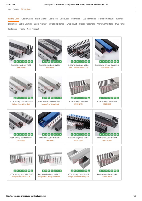
Wiring Duct Cable Gland Brass Gland Cable Tie Conducts Terminals Lug Terminals Flexible Conduit Tubings Bushings Cable Clamps Cable MarkerWrapping Bands Snap Rivet Plastic FastenersWire ConnectorsPCB PartsFastenersToolsNew ProductHome / Products / Wiring DuctRCCN Wiring Duct VDRF8mm*12mmRCCN Wiring Duct HVDRF4mm*6mmRCCN Wiring Duct VDRCWide Close Slot Wiring DuctRCCN Solid Wiring Duct SDRSolid Wiring DuctRCCN Wiring Duct VDRF-HFHalogen Free Wiring DuctRCCN Wiring Duct HVDRF-…Halogen Free Wiring DuctRCCN Wiring Duct VDR8MM*12MMRCCN Wiring Duct HVDR5MM*8MMRCCN Wiring Duct HVDRT44MM*6MMRCCN Wiring Duct HVDRT5MM*8MMRCCN Wiring Duct VDRT8MM*12MMRCCN Wiring Duct GDRF6mm*6.5mmRCCN Wiring Duct VDRT-HFHalogen Free Wiring DuctRCCN Wiring Duct HVDRT…Halogen Free Wiring Duct HVDR…RCCN Wiring Duct SDRHFHalogen Free Solid Wiring DuctRCCN Wiring Duct VDRL10mm*15mmRCCN Wiring Duct VDRFZ Wide Slot Wiring Duct RCCN Wiring Duct HVDRFZNarrow Slot Wiring DuctRCCN Wiring Duct GDRFZNarrow Slot Wiring DuctRCCN Wiring Duct VDRCL17mm*8mmRCCN Wiring Duct Wiring Duct RCCN Divider WallDivider WallRCCN Wiring Duct HVDRFTNarrow Slot Wiring DuctRCCN Duct Covers DCDuct CoversRCCN Wiring Duct VDRU Wide Slot Wiring Duct RCCN Close Slot VDRCTClose Slot Wiring DuctRCCN Wiring Duct FDFlexible Wiring DuctRCCN Wiring Duct RDRound Wiring DuctRCCN Wiring Duct TC Telephone Wiring Duct RCCN Wiring Duct SDORound Insulating ConduitRCCN Wiring Duct SDROWiring DuctRCCN Wiring Retainer WRRCCN Wiring RetainerRCCN Snap Rivet SR Push Nylon Snap Rivet SR RCCN FWR M ark FWRFWR MarkRCCN Double-Coated Foa…Double-Coated Foam TapeSelf Adhesive B acked M ou…RCCN Self Adhesive Backed Mou…RCCN Saddle Tie M ounts Saddle Tie MountsRCCN Duct CornerDuct Corner/Joining StripsRCCN Wiring Duct WT-1Wiring Duct CutterRCCN Wiring Duct WT-3Wiring Duct CutterRCCN Cutter machine WT-4Cutter machineRCCN Tool TNR-1Nylon Rivet Installation ToolRCCN Diagonal Pliers DP-6Diagonal PliersRCCN Din RailsDin RailsRCCN Din Rails LSDin Rails RCCN Din rail cutterDin rail cutterRCCN Din rail cutterDin rail cutterRCCN Terminals JWD1Feed-Through TerminalsRCCN Terminals JWD9 Feed-Through Terminals RCCN Terminals JWD2Feed-Through TerminalsRCCN Terminals JY1-2Feed-Through TerminalsRCCN Terminals JHY1Feed-Through TerminalsRCCN Terminals JH9 Feed-Through Terminals RCCN Nylon Drag chain JFNylon Drag chainRCCN Wiring Duct HVDRF4mm*6mm Narrow Slot Wiring …RCCN Wiring Duct VDRF8mm*12mm Wide Slot Wiring D…A total of 56 records , 1/1First Prev1Next End。
CS5532-BSZR;CS5534-BSZR;CDB5532U;中文规格书,Datasheet资料

Copyright © Cirrus Logic, Inc. 2008CS5532/34-BS24-bit ∆Σ ADCs with Ultra-low-noise PGIAFeaturesChopper-stabilized PGIA (ProgrammableGain Instrumentation Amplifier, 1x to 64x)– 6 nV/√Hz @ 0.1 Hz (No 1/f noise) at 64x –1200pA Input Current with Gains >1 Delta-sigma Analog-to-digital Converter –Linearity Error: 0.0007% FS–Noise-free Resolution: Up to 23 bits Two- or Four-channel Differential MUX Scalable Input Span via Calibration –±5 mV to differential ±2.5VScalable V REF Input: Up to Analog Supply Simple Three-wire Serial Interface –SPI™ and Microwire™ Compatible –Schmitt Trigger on Serial Clock (SCLK) R/W Calibration Registers Per Channel Selectable Word Rates: 6.25 to 3,840 Sps Selectable 50 or 60 Hz RejectionPower Supply Configurations–VA+ = +5 V; VA- = 0 V; VD+ = +3 V to +5 V–VA+ = +2.5 V; VA- = -2.5 V; VD+ = +3 V to +5 V –VA+ = +3 V; VA- = -3 V; VD+ = +3 VGeneral DescriptionThe CS5532/34 are highly integrated ∆Σ Analog-to-Digi-tal Converters (ADCs) which use charge-balance techniques to achieve 24-bit performance. The ADCs are optimized for measuring low-level unipolar or bipolar signals in weigh scale, process control, scientific, and medical applications.To accommodate these applications, the ADCs come as either two-channel (CS5532) or four-channel (CS5534)devices and include a very low-noise, chopper-stabilized instrumentation amplifier (6 nV/√Hz @ 0.1 Hz) with se-lectable gains of 1×, 2×, 4×, 8×, 16×, 32×, and 64×.These ADCs also include a fourth-order ∆Σ modulator followed by a digital filter which provides twenty selectable output word rates of 6.25, 7.5, 12.5, 15, 25, 30, 50, 60, 100,120, 200, 240, 400, 480, 800, 960, 1600, 1920, 3200, and 3840 Sps (MCLK =4.9152MHz).To ease communication between the ADCs and a micro-controller, the converters include a simple three-wire se-rial interface which is SPI™ and Microwire™ compatible with a Schmitt-trigger input on the serial clock (SCLK).High dynamic range, programmable output rates, and flexible power supply options makes these ADCs ideal solutions for weigh scale and process control applications.ORDERING INFORMATIONSee page 47VA+C1C2VREF+VREF-VD+DIFFERENTIAL 4TH ORDER ∆ΣMODULATORPGIA 1,2,4,8,16PROGRAMMABLE SINC FIR FILTERMUX(CS5534SHOWN)AIN1+AIN1-AIN2+AIN2-AIN3+AIN3-AIN4+AIN4-SERIAL INTERFACELATCHCLOCK GENERATORCALIBRATION SRAM/CONTROLLOGICDGNDCSSDI SDO SCLKOSC2OSC1A1A0/GUARD VA-32,64OCT ‘08TABLE OF CONTENTS1.CHARACTERISTICS AND SPECIFICATIONS (4)ANALOG CHARACTERISTICS (4)TYPICAL RMS NOISE (NV) (7)TYPICAL NOISE-FREE RESOLUTION(BITS) (7)5 V DIGITAL CHARACTERISTICS (8)3 V DIGITAL CHARACTERISTICS (8)DYNAMIC CHARACTERISTICS (9)ABSOLUTE MAXIMUM RATINGS (9)SWITCHING CHARACTERISTICS (10)2.GENERAL DESCRIPTION (12)2.1.Analog Input (12)2.1.1. Analog Input Span (13)2.1.2. Multiplexed Settling Limitations (13)2.1.3. Voltage Noise Density Performance (13)2.1.4. No Offset DAC (14)2.2.Overview of ADC Register Structure and Operating Modes (14)2.2.1. System Initialization (15)2.2.2. Serial Port Interface (22)2.2.3. Reading/Writing On-Chip Registers (23)2.3.Configuration Register (23)2.3.1. Power Consumption (23)2.3.2. System Reset Sequence (23)2.3.3. Input Short (24)2.3.4. Guard Signal (24)2.3.5. Voltage Reference Select (24)2.3.6. Output Latch Pins (24)2.3.7. Offset and Gain Select (25)2.3.8. Filter Rate Select (25)2.4.Setting up the CSRs for a Measurement (27)2.5.Calibration (30)2.5.1. Calibration Registers (30)2.5.2. Performing Calibrations (31)2.5.3. Self Calibration (31)2.5.4. System Calibration (32)2.5.5. Calibration Tips (32)2.5.6. Limitations in Calibration Range (33)2.6.Performing Conversions (33)2.6.1. Single Conversion Mode (33)2.6.2. Continuous Conversion Mode (34)2.6.3. Examples of Using CSRs to Perform Conversions and Calibrations (35)ing Multiple ADCs Synchronously (36)2.8.Conversion Output Coding (36)2.9.Digital Filter (38)2.10.Clock Generator (39)2.11.Power Supply Arrangements (39)2.12.Getting Started (43)2.13.PCB Layout (43)3.PIN DESCRIPTIONS (44)4.SPECIFICATION DEFINITIONS (46)5.ORDERING INFORMATION (47)6.ENVIRONMENTAL, MANUFACTURING, & HANDLING INFORMATION (47)7.PACKAGE DRAWINGS (48)LIST OF FIGURESFigure 1. SDI Write Timing (Not to Scale) (11)Figure 2. SDO Read Timing (Not to Scale) (11)Figure 3. Multiplexer Configuration (12)Figure 4. Input models for AIN+ and AIN- pins (13)Figure 5. Measured Voltage Noise Density (13)Figure 6. CS5532/34 Register Diagram (14)Figure 7. Command and Data Word Timing (22)Figure 8. Guard Signal Shielding Scheme (24)Figure 9. Input Reference Model when VRS = 1 (25)Figure 10. Input Reference Model when VRS = 0 (25)Figure 11. Self Calibration of Offset (32)Figure 12. Self Calibration of Gain (32)Figure 13. System Calibration of Offset (32)Figure 14. System Calibration of Gain (32)Figure 15. Synchronizing Multiple ADCs (36)Figure 16. Digital Filter Response (WR = 60 Sps) (38)Figure 18. 120 Sps Filter Phase Plot to 120 Hz (38)Figure 17. 120 Sps Filter Magnitude Plot to 120 Hz (38)Figure 19. Z-Transforms of Digital Filters (38)Figure 20. On-chip Oscillator Model (39)Figure 21. CS5532 Configured with a Single +5 V Supply (40)Figure 22. CS5532 Configured with ±2.5 V Analog Supplies (41)Figure 23. CS5532 Configured with ±3 V Analog Supplies (41)Figure 24. CS5532 Configured for Thermocouple Measurement (42)Figure 25. Bridge with Series Resistors (42)LIST OF TABLESTable 1. Conversion Timing – Single Mode (34)Table 2. Conversion Timing – Continuous Mode (35)Table 3. Command Byte Pointer (35)Table 4. Output Coding for 24-bit CS5532 and CS5534 (37)1. CHARACTERISTICS AND SPECIFICATIONSANALOG CHARACTERISTICS(VA+, VD+ = 5 V ±5%; VREF+ = 5 V; VA-, VREF-, DGND = 0 V; MCLK = 4.9152 MHz; OWR (Output Word Rate) = 60 Sps; Bipolar Mode; Gain = 32)(See Notes 1 and 2.)Notes: 1.Applies after system calibration at any temperature within -40 °C ~ +85 °C.2.Specifications guaranteed by design, characterization, and/or test. LSB is 24 bits.3. This specification applies to the device only and does not include any effects by external parasiticthermocouples. The PGIA contributes 5 nV of offset drift, and the modulator contributes 640/G nV of offset drift, where G is the amplifier gain setting.4.Drift over specified temperature range after calibration at power-up at 25 °C.ParameterMin Typ Max Unit Accuracy Linearity Error -±0.0007±0.0015%FS No Missing Codes 24--Bits Bipolar Offset -±16±32LSB 24Unipolar Offset-±32±64LSB 24Offset Drift(Notes 3 and 4)-640/G +5-nV/°C Bipolar Full-scale Error -±8±31ppm Unipolar Full-scale Error -±16±62ppm Full-scale Drift(Note 4)-2-ppm/°CANALOG CHARACTERISTICS (Continued)(See Notes 1 and 2.)Notes: 5.The voltage on the analog inputs is amplified by the PGIA, and becomes V CM ± Gain*(AIN+ - AIN-)/2 atthe differential outputs of the amplifier. In addition to the input common mode + signal requirements for the analog input pins, the differential outputs of the amplifier must remain between (VA- + 0.1 V) and (VA+ - 0.1 V) to avoid saturation of the output stage.6.See the section of the data sheet which discusses input models.7.Input current on AIN+ or AIN- (with Gain =1), or VREF+ or VREF- may increase to 250nA if operatedwithin 50mV of VA+ or VA-. This is due to the rough charge buffer being saturated under these conditions.ParameterMin TypMaxUnitAnalog InputCommon Mode + Signal on AIN+ or AIN-Bipolar/Unipolar ModeGain = 1 Gain = 2, 4, 8, 16, 32, 64(Note 5)VA-VA- + 0.7--VA+VA+ - 1.7V V CVF Current on AIN+ or AIN-Gain = 1 (Note 6, 7)Gain = 2, 4, 8, 16, 32, 64--501200--nA pA Input Current Noise Gain = 1 Gain = 2, 4, 8, 16, 32, 64--2001--pA/√Hz pA/√Hz Input Leakage for Mux when Off (at 25 °C)-10-pA Off-channel Mux Isolation -120-dB Open Circuit Detect Current 100300-nA Common Mode Rejection dc, Gain = 1dc, Gain = 6450, 60 Hz ---90130120---dB dB dB Input Capacitance -60-pF Guard Drive Output -20-µA Voltage Reference Input Range (VREF+) - (VREF-)1 2.5(VA+)-(VA-)V CVF Current (Note 6, 7)-50-nA Common Mode Rejection dc 50, 60 Hz --120120--dB dB Input Capacitance 11-22pF System Calibration Specifications Full-scale Calibration Range Bipolar/Unipolar Mode 3-110%FS Offset Calibration Range Bipolar Mode -100-100%FS Offset Calibration Range Unipolar Mode -90-90%FSANALOG CHARACTERISTICS (Continued)(See Notes 1 and 2.)8.All outputs unloaded. All input CMOS levels.9.Power is specified when the instrumentation amplifier (Gain ≥ 2) is on. Analog supply current is reducedby approximately 1/2 when the instrumentation amplifier is off (Gain = 1).10.Tested with 100 mV change on VA+ or VA-.ParameterMinTypMaxUnitPower SuppliesDC Power Supply Currents (Normal Mode)I A+, I A-I D+- - 130.5151mA mA Power ConsumptionNormal Mode (Notes 8 and 9)Standby Sleep---70450080--mW mW µW Power Supply Rejection (Note 10)dc Positive Supplies dc Negative Supply--115115--dB dBTYPICAL RMS NOISE (nV)(See notes 11, 12, 13 and 14)Notes:11.The -B devices provide the best noise specifications.12.Wideband noise aliased into the baseband. Referred to the input. Typical values shown for 25 °C.13.For Peak-to-Peak Noise multiply by 6.6 for all ranges and output rates.14.Word rates and -3dB points with FRS = 0. When FRS = 1, word rates and -3dB points scale by 5/6.TYPICAL NOISE-FREE RESOLUTION(BITS)(See Notes 15 and 16)15.Noise-free resolution listed is for bipolar operation, and is calculated as LOG((Input Span)/(6.6xRMSNoise))/LOG(2) rounded to the nearest bit. For unipolar operation, the input span is 1/2 as large, so one bit is lost. The input span is calculated in the analog input span section of the data sheet. The noise-free resolution table is computed with a value of 1.0 in the gain register. Values other than 1.0 will scale the noise, and change the noise-free resolution accordingly.16.“Noise-free resolution” is not the same as “effective resolution”. Effective resolution is based on theRMS noise value, while noise-free resolution is based on a peak-to-peak noise value specified as 6.6 times the RMS noise value. Effective resolution is calculated as LOG((Input Span)/(RMS Noise))/LOG(2).Specifications are subject to change without notice.Output Word Rate (Sps)-3 dB Filter Frequency (Hz)Instrumentation Amplifier Gain x64x32x16x8x4x2x17.5 1.948.59101526509915 3.88121315213770139307.751718213052991966015.524252942731402771203134364259103198392240628013626051410202050409048012211319436973014502900581096023015927452310302060411082301,920390260470912181036207230145003,84078013602690538010800215004300086000Output Word Rate (Sps)-3 dB Filter Frequency (Hz)Instrumentation Amplifier Gainx64x32x16x8x4x2x17.5 1.942021222323232315 3.8820212222222222307.75192021222222226015.5192021212121211203118192021212121240621717181818181848012217171717171717960230161617171717171,920390161616161616163,840780131313131313135 V DIGITAL CHARACTERISTICS(VA+, VD+ = 5 V ±5%; VA-, DGND = 0 V; See Notes 2 and 17.)3 V DIGITAL CHARACTERISTICS(T A = 25 °C; VA+ = 5V ±5%; VD+ = 3.0V±10%; VA-, DGND = 0V; See Notes 2 and 17.)17.All measurements performed under static conditions.ParameterSymbol Min Typ Max Unit High-level Input Voltage All Pins Except SCLKSCLK V IH 0.6 VD+(VD+) - 0.45--VD+VD+V Low-level Input Voltage All Pins Except SCLKSCLK V IL 0.00.0-0.80.6V High-level Output Voltage A0 and A1, I out = -1.0 mASDO, I out = -5.0 mA V OH (VA+) - 1.0(VD+) - 1.0--V Low-level Output Voltage A0 and A1, I out = 1.0 mASDO, I out = 5.0 mAV OL --(VA-) + 0.40.4V Input Leakage Current I in -±1±10µA SDO Tri-State Leakage Current I OZ --±10µA Digital Output Pin CapacitanceC out-9-pFParameterSymbol Min Typ Max Unit High-level Input Voltage All Pins Except SCLKSCLK V IH 0.6 VD+(VD+) - 0.45-VD+VD+V Low-level Input Voltage All Pins Except SCLKSCLK V IL 0.00.0-0.80.6V High-level Output Voltage A0 and A1, I out = -1.0 mASDO, I out = -5.0 mA V OH (VA+) - 1.0(VD+) - 1.0--V Low-level Output Voltage A0 and A1, I out = 1.0 mASDO, I out = 5.0 mAV OL --(VA-) + 0.40.4V Input Leakage Current I in -±1±10µA SDO Tri-State Leakage Current I OZ --±10µA Digital Output Pin CapacitanceC out-9-pFDYNAMIC CHARACTERISTICS18.The ADCs use a Sinc 5 filter for the 3200 Sps and 3840 Sps output word rate (OWR) and a Sinc 5 filterfollowed by a Sinc 3 filter for the other OWRs. OWR sinc5 refers to the 3200 Sps (FRS = 1) or 3840 Sps (FRS = 0) word rate associated with the Sinc 5 filter.19.The single conversion mode only outputs fully settled conversions. See Table 1 for more details aboutsingle conversion mode timing. OWR SC is used here to designate the different conversion time associated with single conversions.20.The continuous conversion mode outputs every conversion. This means that the filter’s settling timewith a full scale step input in the continuous conversion mode is dictated by the OWR.ABSOLUTE MAXIMUM RATINGS(DGND = 0 V; See Note 21.)Notes:21.All voltages with respect to ground.22.VA+ and VA- must satisfy {(VA+) - (VA-)} ≤ +6.6 V.23.VD+ and VA- must satisfy {(VD+) - (VA-)} ≤ +7.5 V.24.Applies to all pins including continuous overvoltage conditions at the analog input (AIN) pins.25.Transient current of up to 100 mA will not cause SCR latch-up. Maximum input current for a power supply pin is ±50 mA.26.Total power dissipation, including all input currents and output currents.WARNING:Operation at or beyond these limits may result in permanent damage to the device.Normal operation is not guaranteed at these extremes.ParameterSymbol Ratio Unit Modulator Sampling Ratef s MCLK/16Sps Filter Settling Time to 1/2 LSB (Full Scale Step Input)Single Conversion mode (Notes 18, 19, and 20)Continuous Conversion mode, OWR < 3200 Sps Continuous Conversion mode, OWR ≥ 3200 Spst s t s t s1/OWR SC5/OWR sinc5 + 3/OWR5/OWRs s sParameterSymbol Min Typ Max Unit DC Power Supplies(Notes 22 and 23)Positive Digital Positive Analog Negative Analog VD+VA+VA--0.3-0.3+0.3---+6.0+6.0-3.75V V V Input Current, Any Pin Except Supplies (Notes 24 and 25)I IN --±10mA Output Current I OUT--±25mA Power Dissipation (Note 26)PDN --500mW Analog Input Voltage VREF pins AIN PinsV INR V INA (VA-) -0.3(VA-) -0.3--(VA+) + 0.3(VA+) + 0.3V V Digital Input VoltageV IND -0.3-(VD+) + 0.3V Ambient Operating Temperature T A -40-85°C Storage Temperature T stg-65-150°CSWITCHING CHARACTERISTICS(VA+ = 2.5 V or 5 V ±5%; VA- = -2.5V±5% or 0 V; VD+ = 3.0 V ±10% or 5 V ±5%;DGND = 0 V; Levels: Logic 0 = 0 V, Logic 1 = VD+; C L = 50 pF; See Figures 1 and 2.)Notes:27.Device parameters are specified with a 4.9152 MHz clock.28.Specified using 10% and 90% points on waveform of interest. Output loaded with 50pF.29.Oscillator start-up time varies with crystal parameters. This specification does not apply when using anexternal clock source.ParameterSymbol Min Typ MaxUnitMaster Clock Frequency (Note 27)External Clock or Crystal OscillatorMCLK1 4.91525MHz Master Clock Duty Cycle 40-60%Rise Times(Note 28)Any Digital Input Except SCLKSCLKAny Digital Output t rise-----50 1.0100-µs µs ns Fall Times(Note 28)Any Digital Input Except SCLKSCLKAny Digital Output t fall-----50 1.0100-µs µs ns Start-upOscillator Start-up Time XTAL = 4.9152 MHz(Note 29)t ost-20-ms Serial Port Timing Serial Clock Frequency SCLK 0-2MHz Serial Clock Pulse Width High Pulse Width Lowt 1t 2250250----ns nsSDI Write TimingCS Enable to Valid Latch Clock t 350--ns Data Set-up Time prior to SCLK rising t 450--ns Data Hold Time After SCLK Rising t 5100--ns SCLK Falling Prior to CS Disable t 6100--nsSDO Read Timing CS to Data Validt 7--150ns SCLK Falling to New Data Bit t 8--150ns CS Rising to SDO Hi-Zt 9--150ns分销商库存信息:CIRRUS-LOGICCS5532-BSZR CS5534-BSZR CDB5532U。
rccmr标准

rccmr标准
RCC-MR(Recommendations for the Conduct, Reporting, Editing and Publication of Scholarly work in Medical Journals)是由国际医学期刊
编辑委员会(International Committee of Medical Journal Editors,ICMJE)发布的,是一套有关医学期刊投稿指南和规范的推荐标准。
RCC-MR标准包括以下内容:
1. 研究设计:应明确说明研究的设计和实施方式,包括研究目的、研究问题、样本量、研究方法、数据收集和分析等。
2. 伦理问题:应说明研究是否符合伦理标准,包括伦理审查和受试者知情同意等。
3. 报告规范:应遵循国际通用的报告规范,如CONSORT、STROBE、SPIRIT等,以便于读者理解和评价研究结果。
4. 语言和编辑:投稿应使用英文或其他国际通用语言,并经过专业编辑人员进行语言和格式的修改,以确保文章质量和可读性。
5. 作者贡献:应明确作者对研究的贡献,包括设计、实施、分析和解释等。
6. 利益冲突:应声明作者是否存在利益冲突,如与研究对象或研究结果相关的经济利益或其他利益关系。
7. 数据共享:应说明是否可以共享原始数据或生物样本,以及共享的方式和条件。
8. 参考文献:应引用可靠的文献来源,并遵循相应的引用格式规范。
9. 版权问题:应说明作者对文章的版权归属和许可使用情况。
10. 投稿信:应在投稿时提供一封简短的信件,说明研究的目的、方法、结
果和结论等。
这些标准旨在提高医学期刊论文的质量和可靠性,促进学术交流和知识传播。
线槽EN(8)

C56C61C61C62C62C61C104C104C63C63C64C64C64C65C66C67C68WT-1WT-3tools TNR-1C59 connectors3575用3515用C73-C76BC type cable terminals C78C79C80C81C81C84C85C85C86C86C87C88C88C90C93C94C94C96C97C97C98C100C100C101C101C101terminalsTerminal plier FN-1Terminal plier FN-2Terminal plier YYT-120Terminal plier YYT-240Functions shell-offplier WS 5000Auto shell-off plierAuto adjustedshell-off plier YY-318Auto adjustedshell-off plier YY-475Wire plier KT-1cutter YY-858conduit cutterHG-3AA BBCDGFE GHIJKAC B59AES C95AG A1A-G A26A-G A29A-GL A26A-GL A29AG-LH A16AG-SR A4AG-SRH A19AG-SRL A4AG-SRLH A19AG-WH A16A-LED B105ALP B97A-M A27A-ML A27AMP C104AMS-HST B120A-NPT A26A-NPT A29A-NPTL A26A-NPTL A29AP B60A-PG A28A-PGL A28ASC C91ATC B60AWS B71BC BCBF B39BF C80BG A73BG-B A46BG-BV0 A46BGC A72BGE A72BGF-G A56BGF-GL A58BGF-M A55BGF-ML A57BGF-NPT A56BGF-NPTL A58BGF-PG A56BGF-PGL A58BGH A71BGK A66BG-NB A48BG-NG A48BGR-NB A50BGN-G A64BGN-M A63BGN-NPT A64BGN-PG A64BG-NBV0 A48BG-P A73BGQ-BG A70BGQF-M A53BGQF-PG A53BGQ-G A52BGQ-M A51BGQ-NPT A52BGQ-PG A52BGR-B A47BGR-BV0 A46BGR-BV0 A47BGR-N A48BGR-NBH A51BGS A71BGT A66BGW-M A54BGW-PG A54BGX-G A60BGX-GL A62BGX-M A59BGX-ML A61BGX-NPT A60BGX-NPTL A62BGX-PG A60BGX-PGL A62BGY A65BHMWS B92BHS C86BL C100B-LED B106BMS B77BN C86BOX C102BS8 B88BSC C92BT B78C45 C100CBP B81CBS B96CDR-CL C49CE B53CE-V0 B53CL B62CL C97C-LED B107CM B24CS B75CS B76CSC C93CWC C97CZ C63DBF C82DBN C82DC C52DCS C58DF B49DF B51DF C57DJS C58DL C98DLCBS B87D-LED B108DLSP1 B83DLSPTH B79DNF A87DNF A87DNL A87DNN A87DP C59DT C63DT C98EC B20ECB B21EC-J B21ED B67ED-V0 B68E-LED B108ELM A90ELN A92EN C78EPDM B116ET C77ET-N C87EW C78EW-N C88FA C83FB C83FC B61FC B62FCP B62FCT B62FD C55FF B39F-LED B108FN C103FN C86G A3GA A31GA-EMC A35GA-L A33GA-LEMC A37GAS A41GC45 C94GC90 C94GDR C23GDR C24GDR-FZ C45GDR-FZ C46G-EHD B2G-EHD-CS B5G-EHD-HS B6G-EHDUV B4G-EHDV0 B7GGB A9GGB-SR A10G-H A18G-HD B2G-HD-CS B5G-HDE B8G-HDG B8G-HD-HS B6G-HDR B8G-HDSU B4G-HDU B4G-HDV0 B7G-HDY B8G-IE B8G-IG B8G-IR B8G-IY B8GM B66G-M B1GMC B66G-M-CS B5G-ME B8G-MG B8G-M-HS B6G-MR B8GMT-160 B10G-MUV B3G-MV0 B7G-MY B8GS A39G-ST B1G-ST-CS B5G-STE B8G-STG B8G-ST-HS B6G-STR B8G-STUV B3G-STV0 B7G-STY B8HC B57HC C58HCB B112HCBS B82HES C96HG C104HP B65HPC B98HPM B98HS B116HST B111HST-YG B113HTFB B90HTMB B90HTP B77HTS B77HTSB B89HV B11HVDR C5HVDR C6HVDR C15HVDR C16HVDR C19HVDR C20HVDR C50HVDR-FT C51HVDR-FZ C42HVDR-H C33ICM-M A91JF C65JF C66JF C67JF C68JH9 C64JHY C64JIS-G A42J-S B59JWD C63JWD C64KG B67KG-N B69KG-NT B69KG-NT2 B69KGS B67KGS-V0 B68KG-V0 B68KP B29KS B28KT C104K LM MPONPSTRSU VWYZKW B56KWS B73LCBS B85LCBSC B91LCBSM B86LED B109LM-IR B26LN A94LS C62LSC C62LTS C61LVA C79LVB C80LWS B93LWS B94M A22MB B23MBB50MBG-SR A10MC A75MCBP B81 MCL A75MCLS A77MCRA74MCR-CAP A84MCR-EX A77MCRS A76MCS A76MG A5MGA A6MGAA30MGA-EMC A34MGA-H A12MGA-LA32MGA-LEMC A36MGAS A40MGA-SR A11MGB A8 MGBL A8 MGBL-SR A10MGEA A14 MGK B16 MGR B16 MGT B15 ML B14 M-L A23ML-B B15 M-LD A24 MLN A94 M-LS A24 MMB B97 MP B96MP B97 MPS B82 MR C104 MS A38 MS B14 MS B21M-S A2 MSP A89 MSPDL B81 MSPDLN B81 MT B23 MWSB93MWSB B95 N B23 NBE A83 NBF A82 NBG A78 NBK A83NBL A79 NBN A81 NBW A80 NCR B40 NCRS B99 NEG C104NGB A9NGB-SR A10 NPT A3 NPTAA31 NPTA-EMC A35 NPTA-L A33NPTAS A41 NPT-HA18 NPT-LEMC A37 NPTS A39 NPT-SRH A19 NSCH B102 NSCR B104NSCS B101NSOH B103 NSPH B100 NWS B93 NWS B94 OC B24 OMR B22OR A95 OSB B66 OT C101 PA B30 PA B55 PA-V0 B56PB-BT A86 PB-C A84 PB-LB A85 PB-LL A85 PB-T A86 PB-V A84PB-X A86 PC B98 PCV B10 PE B33 PET B30 PF B42 PFS B59 PG A2 PG A25P-G A21 PGA A7 PGAA31 PGA-EMC A35 PGA-H A13 PGA-LA33PGA-LEMC A37 PGAS A41PGA-SR A11 PGB A9 PGB-SRA10PG-H A17 PG-L A2 PG-L A25 PG-LR A85 PG-LS A25 PGS A39 PG-S A25PG-SR A4PG-SRH A19PJ-M A43PJ-G A43PJ-PG A43PJ-PG A43P-M A20P-ML A20PMT-115 B17 PMT-175HD B11 PN B41 PN C85 P-NPT A21 P-PG A21 PS B76 PST B82 PTCV B18 PV C81 PW B41PWV B10 R A95 R C73 RCV B11 RD C55 REM A90REN A92 RF C72 RF-N C90 RH B72 RJ B25 RLSP B84 RMC B17 RS B75 RSB B66SB B65 SC C99 SCBS4 B88 SCM B114 SDO C56 SDR C27SDR C28 SDR C50 SDR-H C34 SDRO C56 SFC B61 SFF B39 SG B52 SG-SP B35 SKC A69 SKM A67SKO A68 SKP A69 SKT A70 SKU A68SKUD A68SL B52 SMB24SM-IRB26 SOTL B92 SP A88SP B76 SP B79 SPK-M A44 SP-MDL B80 SPT A93 SR B34SRC B36 SRH B37SRP A15 SRS B38 SRS B83 SRT B36 SRT B117 ST B74 ST-A B74ST-C B74 SW B54 T B13 TC C56TCM-M A91 TCN A93 TCV B12 TFL B119 TG B19 TNR C59 TNR C104 TP B27 TS B60 TS C104 TSC B26 TT B71 TTB B71 TV B13 TZ B27 UC B58 UM B25 UY B25 V C88VDC C50VDR C1VDR C13VDR-C C9VDR-CT C54VDR-FZ C38VDR-H C31VDR-L C35 VDR-U C53 W3F2 B114 WB B32 WBT B32 WCT B12 WR C57 WS C104 WT C59 WT C104 Y C70 YAC C103 YF C69 YF-N C89 YY C104 ZGC63RCCN WIRING DUCT ORDER CODE:type/slot widthstyleW×HVDRVDR8080F: VDR=8mm slot width 8080=W宽xH高 F=with resistan VDR8080FW: VDR=8mm出线孔 8080=W宽xH高 F=with resistan HVDR8080F: HVDR=4mm出线孔 8080=W宽xW高 F=with resistan HVDR8080FW:HVDR=4mm出线孔 8080=W宽xW高 F=with resistan Part No. details 型号详细说明:FVDR-F=8mm slot width HVDR-F=4mm slot width HVDR=5mm slot width HVD-T=5mm slot width VDR-L=10mm slot widthVDR-C=8.5&10mm slot width VDR-LC=17mm slot width GDR-F=6mm slot width SDR=solid wiring duct HVDR-FT=4mm slot width VDR-CT=8.5&10mm slot widthF=with resistantF=有分隔齿 with resistant无代码blank =无分隔齿no resistantT=无分隔齿no resistantL=无分隔齿大孔no resistant,bigger slotC=顶部闭口close at the topLC=顶部闭口大孔close at the top,bigger slot F=有分隔齿with resistantU=底部大孔bigger mounting hole FT=槽盖带突出cover with protruding HF=耐高温无卤 Halogen free8080Z=with score line Commending type: HVDRF&VDRF。
线槽 HVDR - 环保线槽 - 产品目录 - 线槽 扎带 接头 软管 端子 线束 上海日成电子有限公司RCCN
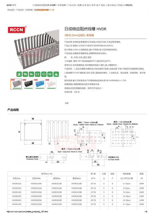
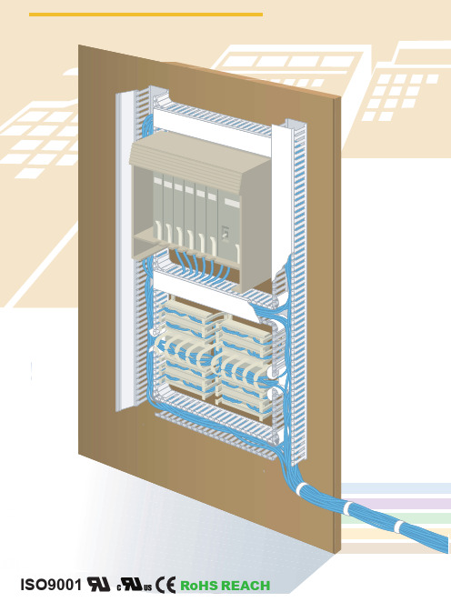
网站首页 / 产品目录 / 环保线槽 / 日成细齿阻燃线槽 HVDR日成细齿阻燃线槽 HVDR1特点:5mm出线孔老规格产品材质:采用低卤素硬质PVC料制成,环保无污染,不含铅等有毒物。
产品认证:美国UL:E306674 欧洲CE,欧洲环保RoHS,REACH。
防火等级:UL94V-0,低烟微卤,遇火不燃烧,防火性及绝缘性特佳。
产品构造:由槽底及槽盖组成,底槽两侧设有出线孔。
颜色 :灰色.白色.蓝色.黑色工作温度 :静态-40°C持续高温至65°C,短时间可达85°C。
使用方法:先将底槽固定,将所要配的线装入槽内,盖上槽盖即可。
产品特性 : 1.反扣式槽盖与槽体设计组合後绝不脱落,且接合面平滑,不割伤手及擦损附近配线。
2.配线槽70°C内不易断裂,变形,变色,装配省时便利。
3.出线孔低、组合容易、拆卸简单、易于配线。
更多选择:量大可按需求生产所需规格或定制长度.例:HVDR8080(L=1.7M)线槽规格以槽盖槽底组合后外部宽高为准表格如没有您需要的规格,我司可开发设计!标准长度:2米/支线槽型号Item No.宽*高W*H 孔宽Q齿宽P电线容量以2.0平方计算装箱/M灰色Gray白色White蓝色Blue黑色BlackHVDR1616HVDR1616W HVDR1616E HVDR1616B16*16583~10pcs300M HVDR2516HVDR2516W HVDR2516E HVDR2516B25*16588-12pcs100M HVDR1520HVDR1520W HVDR1520E HVDR1520B15*20588-12pcs260M HVDR2020HVDR2020W HVDR2020E HVDR2020B20*205810-20pcs240M HVDR4020HVDR4020W HVDR4020E HVDR4020B40*205815-30pcs140M HVDR1525HVDR1525W HVDR1525E HVDR1525B15*25585~15pcs260M 产品规格HVDR2025HVDR2025W HVDR2025E HVDR2025B20*20585~15pcs200M HVDR2525HVDR2525W HVDR2525E HVDR2525B25*255810~25pcs200M HVDR3025HVDR3025W HVDR3025E HVDR3025B30*255812~28pcs160M HVDR4025HVDR4025W HVDR4025E HVDR4025B40*255820-35pcs100M HVDR5025HVDR5025W HVDR5025E HVDR5025B50*255812-28pcs100M HVDR1530HVDR1530W HVDR1530E HVDR1530B15*30588-15pcs180M HVDR2030HVDR2030W HVDR2030E HVDR2030B20*305825-35pcs160M HVDR2530HVDR2530W HVDR2530E HVDR2530B25*305825~35pcs160M HVDR3030HVDR3030W HVDR3030E HVDR3030B30*305825~35pcs140M HVDR4030HVDR4030W HVDR4030E HVDR4030B40*305830~40pcs100M HVDR5030HVDR5030W HVDR5030E HVDR5030B50*305840-50pcs80M HVDR6030HVDR6030W HVDR6030E HVDR6030B60.305850-60pcs60M HVDR2233HVDR2233W HVDR2233E HVDR2233B22.335825-35pcs160M HVDR3333HVDR3333W HVDR3333E HVDR3333B33.335835-45pcs160M HVDR2035HVDR2035W HVDR2035E HVDR2035B20.355830-40pcs100M HVDR3535HVDR3535W HVDR3535E HVDR3535B35*355835~45pcs112M HVDR5035HVDR5035W HVDR5035E HVDR5035B50*355840~60pcs88M HVDR2040HVDR2040W HVDR2040E HVDR2040B20*405816-22pcs11M HVDR2540HVDR2540W HVDR2540E HVDR2540B25*405820~25pcs112M HVDR3540HVDR3540W HVDR3540E HVDR3540B35*405830-45pcs100M HVDR4040HVDR4040W HVDR4040E HVDR4040B40*405860~70pcs100M HVDR6040HVDR6040W HVDR6040E HVDR6040B60*4058100~115pcs68M HVDR8040HVDR8040W HVDR8040E HVDR8040B80*4058120~135pcs48M HVDR10040HVDR10040W HVDR10040E HVDR10040B100*4058120~135pcs32M HVDR12040HVDR12040W HVDR12040E HVDR12040B120*4058140-155pcs/ HVDR2545HVDR2545W HVDR2545E HVDR2545B25*455820~25pcs104M HVDR3345HVDR3345W HVDR3345E HVDR3345B33*455840~55pcs108M HVDR4545HVDR4545W HVDR4545E HVDR4545B45*455860~70pcs72M HVDR6545HVDR6545W HVDR6545E HVDR6545B65*4558110~120pcs56M HVDR2050HVDR2050W HVDR2050E HVDR2050B20*505818-28pcs100M HVDR2550HVDR2550W HVDR2550E HVDR2550B25*505820~30pcs100M HVDR3050HVDR3050W HVDR3050E HVDR3050B30*505825~40pcs84M HVDR3550HVDR3550W HVDR3550E HVDR3550B35*505840~60pcs80M HVDR4050HVDR4050W HVDR4050E HVDR4050B40*505860~70pcs68M HVDR4550HVDR4550W HVDR4550E HVDR4550B45*505870~80pcs60M HVDR5050HVDR5050W HVDR5050E HVDR5050B50*505880~90pcs50M HVDR5550HVDR5550W HVDR5550E HVDR5550B55*505885-95pcs48M HVDR6050HVDR6050W HVDR6050E HVDR6050B60*5058100~120pcs48M HVDR7550HVDR7550W HVDR7550E HVDR7550B75*5058150-170pcs40M HVDR8050HVDR8050W HVDR8050E HVDR8050B80*5058160~180pcs40M HVDR10050HVDR10050W HVDR1005E HVDR10050B100*5058200~250pcs26M HVDR12555HVDR12555W HVDR12555E HVDR12555B125*5558220-270pcs20M HVDR2060HVDR2060W HVDR2060E HVDR2060B20*605835-45pcs100M HVDR2560HVDR2560W HVDR2560E HVDR2560B25*605840~50pcs100M HVDR3060HVDR3060W HVDR3060E HVDR3060B30*605860~80pcs80M HVDR3560HVDR3560W HVDR3560E HVDR3560B35*605890-105pcs78M HVDR4060HVDR4060W HVDR4060E HVDR4060B40*6058100~115pcs60M HVDR4560HVDR4560W HVDR4560E HVDR4560B45*6058110~125pcs30M HVDR5060HVDR5060W HVDR5060E HVDR5060B50*6058120~135pcs60M HVDR6060HVDR6060W HVDR6060E HVDR6060B60*6058120~135pcs48MHVDR8060HVDR8060W HVDR8060E HVDR8060B80*6058180~210pcs36M HVDR10060HVDR10060W HVDR10060E HVDR10060B100*6058240~290pcs28M HVDR11060HVDR11060W HVDR11060E HVDR11060B110*6058250~300pcs48M HVDR12060HVDR12060HVDR12060HVDR12060120*6058260-320pcs48M HVDR15060HVDR15060HVDR15060HVDR15060150*6058300-360pcs16M HVDR2565HVDR2565W HVDR2565E HVDR2565B25*655840~50pcs88M HVDR3365HVDR3365W HVDR3365E HVDR3365B33*655840~70pcs80M HVDR4565HVDR4565W HVDR4565E HVDR4565B45*6558110~120pcs52M HVDR6565HVDR6565W HVDR6565E HVDR6565B65*6558180~200pcs44M HVDR7265HVDR7265W HVDR7265E HVDR7265B72*6558180-230pcs42M HVDR5075HVDR5075W HVDR5075E HVDR5075B50*7558180-210pcs42M HVDR7575HVDR7575W HVDR7575E HVDR7575B75*7558200-240PCS40M HVDR10075HVDR10075W HVDR10075E HVDR10075B100*7558250-290PCS24M HVDR2580HVDR2580W HVDR2580E HVDR2580B25*8058100~120pcs72M HVDR3080HVDR3080W HVDR3080E HVDR3080B30*8058110~125pcs56M HVDR3580HVDR3580W HVDR3580E HVDR3580B35*8058110~130pcs56M HVDR4080HVDR4080W HVDR4080E HVDR4080B40*8058140~160pcs48M HVDR4580HVDR4580W HVDR4580E HVDR4580B45*8058140~160pcs40M HVDR5080HVDR5080W HVDR5080E HVDR5080B50*8058160~180pcs40M HVDR5580HVDR5580W HVDR5580E HVDR5580B55*8058160~180pcs32M HVDR6080HVDR6080W HVDR6080E HVDR6080B60*8058180~210pcs32M HVDR8080HVDR8080W HVDR8080E HVDR8080B80*8058240~290pcs24M HVDR10080HVDR10080W HVDR10080E HVDR10080B100*8058260~350pcs24M HVDR12080HVDR12080W HVDR12080E HVDR12080B120*8058280~380pcs16M HVDR14080HVDR14080W HVDR14080E HVDR14080B140*8058350~450pcs16M HVDR25100HVDR25100W HVDR25100E HVDR25100B25*10058110~160pcs60M HVDR33100HVDR33100W HVDR33100E HVDR33100B33*10058130~175pcs44M HVDR40100HVDR40100W HVDR40100E HVDR40100B40*10058130~175pcs40M HVDR50100HVDR50100W HVDR50100E HVDR50100B50*10058220~250pcs40M HVDR60100HVDR60100W HVDR60100E HVDR60100B60*10058240~290pcs32M HVDR70100HVDR70100W HVDR70100E HVDR70100B40*10058250-340pcs24M HVDR75100HVDR75100W HVDR75100E HVDR75100B75*10058260~350pcs24M HVDR80100HVDR80100W HVDR80100E HVDR80100B80*10058260~350pcs24M HVDR100100HVDR100100W HVDR100100E HVDR100100B100*10058300-400pcs24M HVDR120100HVDR120100W HVDR120100E HVDR120100B120*10058350-450pcs16M HVDR150100HVDR150100W HVDR150100E HVDR150100B150*10058400-650pcs16M HVDR100130HVDR100130W HVDR100130E HVDR100130B100*13058350-450pcs24M HVDR200100HVDR200100W HVDR200100E HVDR200100B200*10058600-800pcs16M HVDR200150HVDR200150W HVDR200150E HVDR200150B200*15058900-1200pcs16M下表为原目录老型号:新型号参考上表。
埃森·墨尔尔系列 xEffect - FRCmM-125 型A RCCB 产品说明说明书
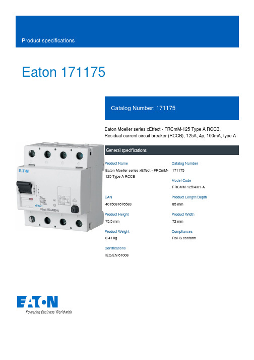
Eaton 171175Eaton Moeller series xEffect - FRCmM-125 Type A RCCB.Residual current circuit breaker (RCCB), 125A, 4p, 100mA, type AGeneral specificationsEaton Moeller series xEffect - FRCmM-125 Type A RCCB171175FRCMM-125/4/01-A401508167658385 mm 75.5 mm 72 mm 0.41 kg RoHS conformIEC/EN 61008Product NameCatalog Number Model Code EANProduct Length/Depth Product Height Product Width Product Weight Compliances Certifications125 AIs the panel builder's responsibility. The specifications for the switchgear must be observed.7035-25 °CMeets the product standard's requirements.Is the panel builder's responsibility. The specifications for the switchgear must be observed.DIN railQuick attachment for DIN-rail EN 50022125 ADoes not apply, since the entire switchgear needs to be evaluated.0.1 A184 V AC - 440 V ACMeets the product standard's requirements.Non-delayedInterlocking device1250 A50 Hz eaton-rcd-application-guide-br019003en-en-us.pdfeaton-xeffect-frcmm-125-rccb-catalog-ca003020en-en-us.pdfeaton-xeffect-industrial-switchgear-range-catalog-ca003002en-en-us.pdf DA-DC-03_FRCmMas_frcmmeaton-frcm-dimensions.jpgeaton-circuit-breaker-xeffect-frcmm-na-rccb-dimensions.epsIL019140ZUdfs_4.dwgdfs_4.stpeaton-frcm-wiring-diagram.jpgRated operational current for specified heat dissipation (In) 10.11 Short-circuit ratingRAL-numberPermitted storage and transport temperature - min10.4 Clearances and creepage distances10.12 Electromagnetic compatibilityMounting MethodAmperage Rating10.2.5 LiftingRated fault current - maxTest circuit range10.2.3.1 Verification of thermal stability of enclosures Tripping timeFitted with:Rated residual making and breaking capacityFrequency rating Application notes Catalogs Certification reports DrawingsInstallation instructions mCAD modelWiring diagrams10.8 Connections for external conductorsIs the panel builder's responsibility.Fault current rating100 mATerminal protectionFinger and hand touch safe, DGUV VS3, EN 50274Special featuresCurrent test marks as perinscriptionMaximum operatingtemperature is 60 °C:Starting at 40 °C, the max.permissible continuouscurrent decreases by 2.2%for every 1 °CSensitivity typePulse-current sensitiveAmbient operating temperature - max60 °CHeat dissipation per pole, current-dependent0 WClimatic proofing25-55 °C / 90-95% relative humidity according to IEC 60068-2Built-in depth70.5 mmShort-circuit rating125 A (max. admissible back-up fuse)FeaturesAdditional equipment possibleResidual current circuit breakerLifespan, electrical4000 operationsConnectable conductor cross section (solid-core) - min1.5 mm²Contact position indicator colorRed / green10.9.3 Impulse withstand voltageIs the panel builder's responsibility.Number of polesFour-poleTerminal capacity (solid wire)1.5 mm² - 16 mm² (2x)1.5 mm² - 50 mm²Ambient operating temperature - min-25 °C10.6 Incorporation of switching devices and componentsDoes not apply, since the entire switchgear needs to be evaluated.Rated short-circuit strength10 kA with back-up fuse10.5 Protection against electric shockDoes not apply, since the entire switchgear needs to be evaluated.Used withFRCmM-125Residual current circuit breakersType AMounting positionAs requiredEquipment heat dissipation, current-dependent22.5 W10.13 Mechanical functionThe device meets the requirements, provided the information in the instruction leaflet (IL) is observed.10.2.6 Mechanical impactDoes not apply, since the entire switchgear needs to be evaluated.10.9.4 Testing of enclosures made of insulating materialIs the panel builder's responsibility.Static heat dissipation, non-current-dependent0 WApplicationSwitchgear for industrial andadvanced commercialapplicationsxEffect - Switchgear forindustrial and advancedcommercial applications10.3 Degree of protection of assembliesDoes not apply, since the entire switchgear needs to be evaluated.Voltage rating (IEC/EN 60947-2)240 V AC / 415 V ACVoltage typeACTerminal capacity (stranded cable)1.5 mm² - 5 mm²1.5 mm² - 16 mm² (2x)Leakage current typeAFrame45 mmBuilt-in width (number of units)70 mm (4 SU)Terminals (top and bottom)Twin-purpose terminalsHeat dissipation capacity0 WImpulse withstand currentPartly surge-proof 250 A250 A (8/20 μs) surge-proofWidth in number of modular spacings4Busbar material thickness0.8 mm - 2 mm10.2.3.2 Verification of resistance of insulating materials to normal heatMeets the product standard's requirements.10.2.3.3 Resist. of insul. mat. to abnormal heat/fire by internal elect. effectsMeets the product standard's requirements.Lifespan, mechanical10000 operationsStatus indicationToggle-center postition10.9.2 Power-frequency electric strengthIs the panel builder's responsibility.Connectable conductor cross section (solid-core) - max50 mm²Degree of protectionIP20, IP40 with suitable enclosureIP20Rated short-time withstand current (Icw)10 kAPollution degree210.7 Internal electrical circuits and connectionsIs the panel builder's responsibility.Connectable conductor cross section (multi-wired) - min 1.5 mm²Rated impulse withstand voltage (Uimp)4 kV10.10 Temperature riseThe panel builder is responsible for the temperature rise calculation. Eaton will provide heat dissipation data for the devices.Connectable conductor cross section (multi-wired) - max 16 mm²TypeFRCmM-125Residual current circuitbreakersType A10.2.2 Corrosion resistanceMeets the product standard's requirements.10.2.4 Resistance to ultra-violet (UV) radiationMeets the product standard's requirements.10.2.7 InscriptionsMeets the product standard's requirements.Surge current capacity0.25 kAPermitted storage and transport temperature - max60 °CEaton Corporation plc Eaton House30 Pembroke Road Dublin 4, Ireland © 2023 Eaton. All Rights Reserved. Eaton is a registered trademark.All other trademarks areproperty of their respectiveowners./socialmedia80 A gG/gL0.1 A415 V440 VAdmissible back-up fuse overload - max Rated fault current - min Rated operational voltage (Ue) - max Rated insulation voltage (Ui)。
威纳尔(Werner)公司产品安装说明书:钢铁和铝制侧箱与包裹箱(Pack Rat)抽屉单元

NOTICEWARNINGDANGERCAUTIONUse specific aluminum upfit components when installing WEATHER GUARD® products to aluminum truck beds. Follow additional instructions if mounting to an aluminum truck bed. There may be left over components depending on upfit.Any modification or unintended use of this product shall immediately void all manufacturers warranties. Manufacturer disclaims all liability for injuries to persons or property resulting from any modification to, or unintended use of this product.Danger of explosion. Do not use this product for storing or transporting flammables, explosives, hazardous materials, or hazardous waste, such as containers of gasoline, solvents, gun powder, dynamite, propane tanks, acetylene tanks and cutting torches. This product is only intended and safe for use in storing and transporting small tools, equipment and other similar materials. Any modifications made to, or unintended use of this product, could create a hazardous condition that can cause death, serious personal injury or property damage.Prior to drilling, so as not to cut or puncture fuel tanks, fuel lines, electric wires, etc., check under vehicle for locations. All floor mounting bolts near the gas tank area should be installed from the underside of the vehicle, to guard against the gas tank being punctured in the event of a collision. This would mean not using Blind Fastener in this area. Holes drilled in this area should be 3/8".To keep debris out of your eyes when checking the underside of the vehicle, or when drilling, always wear protective eyewear.Some of the larger drawers would best be handled by two people, so as not to cause injury to your person.(1) HandleALUMINUM BED UPFIT KIT PARTS LIST - 32-0244(4) Vinyl Tape(1)Zinc Rich Primer(28) 1/2" x 1"Plastic Washer(1) Rear Mounting BracketBLIND FASTENER INSTALLATIONPlace a drop of oil on black oxide bolt for lubrication before assembling.STEP 1STEP 2STEP 2ADrawer RemovalOpen the drawer until it reaches the internal stop brackets. Remove the stop brackets from each upper inside location. Put the brackets and bolts into the drawer for later installation. Install the drawer handle. Carefully pull the drawer completely out of the housing, setting it aside. Lift out the front rollers.Drawer Installation (preferred)Place the housing in position. Slide a mounting plate into each open end of the front and rear skids, but no farther than the leading edge of the slotted hole in the mounting plate. Mark through the hole for drilling. See Blind Fastener Installation Instructions and cautions before drilling. With Blind Fasteners installed, secure by placing the mounting plate as you had for marking.Note: Follow figure to the right as a guide.Drawer Installation (alternate)Place the housing into the position, and mark through the outer slotted holes of each skid. Remove the housing and read the Blind Fastener Installation Instructions and cautions before drilling each of the hole locations. With all Blind Fasteners installed, secure the housing. Reinstall thedrawer to the unit by reversing the removal steps shown.5/16-18 x 1-1/2"Hex Head Bolt5/16-18 x 1-1/2"Hex Head Bolt5/16" Lock Washer5/16" Lock Washer5/16" Flat Washer5/16" Flat Washer MOUNTING PLATE1/2" Hole1/2" Hole5/16-18 Blind Fastener5/16-18 Blind FastenerSTOP BRACKETS DRAWERHANDLE5/16-18 x 3/4" Truss Head Screw5/16-18 Whiz Lock NutFRONT ROLLERSHOUSING5/16-18 x 3/4" Hex Head BoltINSTALLATION INSTRUCTIONSNote: If your truck bed is constructed of aluminum, use zinc rich primer to coat drilled holes.STEP 3Stacking PACK RAT® Drawer UnitsRear Mount Bracket Installation (alternate)If space is critical and/or for some reason you cannot mount the rear in either the preferred method or use the mounting plates at the rear, you may use the rear mounting bracket. Locate the center line of the housing and place the bracket flush against the back and flush to the floor. If necessary, you may turn the bracket so the floor flange is under the rear overhang of the housing. Hole marking will be more difficult. Mark only the two floor holes for drilling. See Blind Fastener Installation Instructions and cautions before drilling. With Blind Fasteners installed, fasten the bracket to the floor. Mark and drill holes on the back of the housing for Blind Fastener installation. With Blind Fasteners installed, replace the housing and secure to the bracket.1/2" Hole1/2" Hole5/16-18 x 1-1/2"Hex Head Bolt5/16-18 x 1"Hex Head Bolt5/16" Lock Washer5/16" Lock Washer 5/16" Flat Washer5/16" Flat Washer5/16-18 Blind Fastener5/16-18 Blind Fastener1/2" Hole1/2" Hole5/16-18 x 1-1/2"Hex Head Bolt5/16-18 x 1"Hex Head Bolt5/16" Lock Washer CENTER LINE OF HOUSING5/16" Lock Washer5/16"Flat Washer5/16" Flat Washer5/16-18 Blind Fastener REAR MOUNTING BRACKETREAR MOUNTING BRACKETINSET• Do not install bolts in the rear of the upper housing at this time.• See Inset below for installation details. Do not use outer-most obround holes, fasteners would obstruct lower unit drawer travel. When stacking PACK RAT® units in an open vehicle, apply sealant (local purchase) to drilled holes in the drawer unit bodies.With the lower PACK RAT® unit properly bolted in place, mount the rear mounting bracket to the top rear edge of the unit as shown. The bracket will be mounted to the bottom first. Put the upper PACK RAT® unit in position on top of the lower and mark the back mounting holes for blind fastener installation. With the upper housing in proper bolting position (with drawer and rollers removed), mark through inner two obround holes in the front mounting skid for Blind Fastener installation. With front Blind Fasteners installed, fasten the upper housing to the lower.Note: STEP 2B。
- 1、下载文档前请自行甄别文档内容的完整性,平台不提供额外的编辑、内容补充、找答案等附加服务。
- 2、"仅部分预览"的文档,不可在线预览部分如存在完整性等问题,可反馈申请退款(可完整预览的文档不适用该条件!)。
- 3、如文档侵犯您的权益,请联系客服反馈,我们会尽快为您处理(人工客服工作时间:9:00-18:30)。
Home / Products / Wiring Duct / RCCN Wiring Duct HVDRFZRCCN Wiring Duct HVDRFZNarrow Slot Wiring DuctWide slot/finger design provides greater sidewall rigidity and can be used with a wide range of wirebundle sizes。
Certificates:UL:E306674 CE:EN50085 RoHS,REACH。
Made of rigid PVCWork Temperature:-40°C to 65°CUL94 Flammability Rating of V-0Provided with mounting holesAvailable color:gray.white.blue.black and other special colorsSpecial design: with score line at the base of trunking, it makesthe fingers easy to separate from the trunking no need to us cutter.Wiring Duct PVC Trunking Wire trunkingItem No.W*H Q PWirecapability/2.0spPack/MGray White Blue BlackHVDR1616FZ HVDR1616FZW HVDR1616FZE HVDR1616FZB16*16553-10pcs300M HVDR2516FZ HVDR2516FZW HVDR2516FZE HVDR2516FZB25*16558-12pcs260M HVDR1520FZ HVDR1520FZW HVDR1520FZE HVDR1520FZB15*20468-12pcs260M HVDR2020FZ HVDR2020FZW HVDR2020FZE HVDR2020FZB20*204610-20pcs240M HVDR4020FZ HVDR4020FZW HVDR4020FZE HVDR4020FZB40*204615-30pcs140M HVDR1525FZ HVDR1525FZW HVDR1525FZE HVDR1525FZB15*25465-15pcs260M HVDR2025FZ HVDR2025FZW HVDR2025FZE HVDR2025FZB20*254612-28pcs160M HVDR2525FZ HVDR2525FZW HVDR2525FZE HVDR2525FZB25*254610~25pcs200M HVDR3025FZ HVDR3025FZW HVDR3025FZE HVDR3025FZB30*254612-28pcs160M HVDR4025FZ HVDR4025FZW HVDR4025FZE HVDR4025FZB40*254620-35pcs100M SpecificationHVDR5025FZ HVDR5025FZW HVDR5025FZE HVDR5025FZB50*254612-28pcs100M HVDR1530FZ HVDR1530FZW HVDR1530FZE HVDR1530FZB15*30468-15pcs180M HVDR2030FZ HVDR2030FZW HVDR2030FZE HVDR2030FZB20*304625-35pcs160M HVDR2530FZ HVDR2530FZW HVDR2530FZE HVDR2530FZB25*304625~35pcs160M HVDR3030FZ HVDR3030FZW HVDR3030FZE HVDR3030FZB30*304625~35pcs140M HVDR4030FZ HVDR4030FZW HVDR4030FZE HVDR4030FZB40*304630-40pcs100M HVDR5030FZ HVDR5030FZW HVDR5030FZE HVDR5030FZB50*304640-50pcs80M HVDR6030FZ HVDR6030FZW HVDR6030FZE HVDR6030FZB60*304650-60pcs60M HVDR2233FZ HVDR2233FZW HVDR2233FZE HVDR2233FZB22*334625-35pcs160M HVDR3333FZ HVDR3333FZW HVDR3333FZE HVDR3333FZB33*334635-45pcs160M HVDR2035FZ HVDR2035FZW HVDR2035FZE HVDR2035FZB20*354630-40pcs100M HVDR3535FZ HVDR3535FZW HVDR3535FZE HVDR3535FZB35*354635-45pcs112M HVDR5035FZ HVDR5035FZW HVDR5035FZE HVDR5035FZB50*354640-60pcs88M HVDR2040FZ HVDR2040FZW HVDR2040FZE HVDR2040FZB20*404616-22pcs110M HVDR2540FZ HVDR2540FZW HVDR2540FZE HVDR2540FZB25*404620~25pcs112M HVDR3540FZ HVDR3540FZW HVDR3540FZE HVDR3540FZB35*404630-45pcs100M HVDR4040FZ HVDR4040FZW HVDR4040FZE HVDR4040FZB40*404660~70pcs100M HVDR6040FZ HVDR6040FZW HVDR6040FZE HVDR6040FZB60*4046100~115pcs68M HVDR8040FZ HVDR8040FZW HVDR8040FZE HVDR8040FZB80*4046120~135pcs48M HVDR10040FZ HVDR10040FZW HVDR10040FZE HVDR10040FZB100*4046120~135pcs32M HVDR12040FZ HVDR12040FZW HVDR12040FZE HVDR12040FZB120*4046140-155pcs/ HVDR2545FZ HVDR2545FZW HVDR2545FZE HVDR2545FZB25*454620-25pcs104M HVDR3345FZ HVDR3345FZW HVDR3345FZE HVDR3345FZB33*454640-55pcs108M HVDR4545FZ HVDR4545FZW HVDR4545FZE HVDR4545FZB45*454660-70pcs72M HVDR6545FZ HVDR6545FZW HVDR6545FZE HVDR6545FZB65*4546110-120pcs56M HVDR2050FZ HVDR2050FZW HVDR2050FZE HVDR2050FZB20*504618-28pcs100M HVDR2550FZ HVDR2550FZW HVDR2550FZE HVDR2550FZB25*504620~30pcs100M HVDR3050FZ HVDR3050FZW HVDR3050FZE HVDR3050FZB30*504625~40pcs84M HVDR3550FZ HVDR3550FZW HVDR3550FZE HVDR3550FZB35*504640~60pcs80M HVDR4050FZ HVDR4050FZW HVDR4050FZE HVDR4050FZB40*504660~70pcs68M HVDR4550FZ HVDR4550FZW HVDR4550FZE HVDR4550FZB45*504670~80pcs60M HVDR5050FZ HVDR5050FZW HVDR5050FZE HVDR5050FZB50*504680~90pcs60M HVDR5550FZ HVDR5550FZW HVDR5550FZE HVDR5550FZB55*504685-95pcs48M HVDR6050FZ HVDR6050FZW HVDR6050FZE HVDR6050FZB60*5046100~120pcs48M HVDR7550FZ HVDR7550FZW HVDR7550FZE HVDR7550FZB75*5046150-170pcs40M HVDR8050FZ HVDR8050FZW HVDR8050FZE HVDR8050FZB80*5046160~180pcs40M HVDR10050FZ HVDR10050FZW HVDR10050FZE HVDR10050FZB100*5046200~250pcs26M HVDR12555FZ HVDR12555FZW HVDR12555FZE HVDR12555FZB125*5546220-270pcs20M HVDR2060FZ HVDR2060FZW HVDR2060FZE HVDR2060FZB20*604635-45pcs100M HVDR2560FZ HVDR2560FZW HVDR2560FZE HVDR2560FZB25*604640~50pcs100M HVDR3060FZ HVDR3060FZW HVDR3060FZE HVDR3060FZB30*604660~80pcs80M HVDR3560FZ HVDR3560FZW HVDR3560FZE HVDR3560FZB35*604690-105pcs78M HVDR4060FZ HVDR4060FZW HVDR4060FZE HVDR4060FZB40*6046100~115pcs60M HVDR4560FZ HVDR4560FZW HVDR4560FZE HVDR4560FZB45*6046110~125pcs30MHVDR5060FZ HVDR5060FZW HVDR5060FZE HVDR5060FZB50*6046120~135pcs60M HVDR6060FZ HVDR6060FZW HVDR6060FZE HVDR6060FZB60*6046120~135pcs48M HVDR8060FZ HVDR8060FZW HVDR8060FZE HVDR8060FZB80*6046180~210pcs36M HVDR10060FZ HVDR10060FZW HVDR10060FZE HVDR10060FZB100*6046240~290pcs28M HVDR11060FZ HVDR11060FZW HVDR11060FZE HVDR11060FZB110*6046250~300pcs48M HVDR12060FZ HVDR12060FZW HVDR12060FZE HVDR12060FZB120*6046260~320pcs48M HVDR15060FZ HVDR15060FZW HVDR15060FZ HVDR15060FZB150*6046300-360pcs16M HVDR2565FZ HVDR2565FZW HVDR2565FZE HVDR2565FZB25*654640-50pcs88M HVDR3565FZ HVDR3565FZW HVDR3565FZE HVDR3565FZB35*654640-70pcs80M HVDR4565FZ HVDR4565FZW HVDR4565FZE HVDR4565FZB45*6546110-120pcs52M HVDR6565FZ HVDR6565FZW HVDR6565FZE HVDR6565FZB65*6546180-200pcs44MHVDR7265FZ HVDR7265FZW HVDR7265FZE HVDR7265FZB72*6546180-230pcs42M HVDR2575FZ HVDR2575FZW HVDR2575FZE HVDR2575FZB25*7546160-190pcs/ HVDR3575FZ HVDR3575FZW HVDR3575FZE HVDR3575FZB35*7546170-200pcs/ HVDR5075FZ HVDR5075FZW HVDR5075FZE HVDR5075FZB50*7546180-210pcs42 HVDR7575FZ HVDR7575FZW HVDR7575FZE HVDR7575FZB75*7546200-240pcs40M HVDR10075FZ HVDR10075FZW HVDR10075FZE HVDR10075FZB100*7546250-290pcs24M HVDR2580FZ HVDR2580FZW HVDR2580FZE HVDR2580FZB25*8046100~120pcs72M HVDR3080FZ HVDR3080FZW HVDR3080FZE HVDR3080FZB30*8046110~125pcs56M HVDR3580FZ HVDR3580FZW HVDR3580FZE HVDR3580FZB35*8046110~130pcs56M HVDR4080FZ HVDR4080FZW HVDR4080FZE HVDR4080FZB40*8046140~160pcs48M HVDR4580FZ HVDR4580FZW HVDR4580FZE HVDR4580FZB45*8046140~160pcs40M HVDR5080FZ HVDR5080FZW HVDR5080FZE HVDR5080FZB508046160~180pcs40M HVDR5580FZ HVDR5580FZW HVDR5580FZE HVDR5580FZB55*8046160~180pcs32M HVDR6080FZ HVDR6080FZW HVDR6080FZE HVDR6080FZB60*8046180~210pcs32M HVDR8080FZ HVDR8080FZW HVDR8080FZE HVDR8080FZB80*8046240~290pcs24M HVDR10080FZ HVDR10080FZW HVDR10080FZE HVDR10080FZB100*8046260~350pcs24M HVDR12080FZ HVDR12080FZW HVDR12080FZE HVDR12080FZB120*8046280~380pcs16M HVDR14080FZ HVDR14080FZW HVDR14080FZE HVDR14080FZB140*8046350~450pcs16M HVDR16080FZ HVDR16080FZW HVDR16080FZE HVDR16080FZB160*804650*-550pcs/ HVDR25100FZ HVDR25100FZW HVDR25100FZE HVDR25100FZB25*10046110~160pcs60M HVDR33100FZ HVDR33100FZW HVDR33100FZE HVDR33100FZB33*10046130~165pcs44M HVDR40100FZ HVDR40100FZW HVDR40100FZE HVDR40100FZB40*10046130~175pcs40M HVDR50100FZ HVDR50100FZW HVDR50100FZE HVDR50100FZB50*10046220~250pcs40M HVDR60100FZ HVDR60100FZW HVDR60100FZE HVDR60100FZB60*10046240~290pcs32M HVDR70100FZ HVDR70100FZW HVDR70100FZE HVDR70100FZB70*10046250-310pcs24M HVDR75100FZ HVDR75100FZW HVDR75100FZE HVDR75100FZB75*10046260~350pcs24M HVDR80100FZ HVDR80100FZW HVDR80100FZE HVDR80100FZB80*10046260~350pcs24M HVDR100100FZ HVDR100100FZW HVDR100100FZE HVDR100100FZB100*10046300~400pcs24M HVDR120100FZ HVDR120100FZW HVDR120100FZE HVDR120100FZB120*10046350~450pcs16M HVDR150100FZ HVDR150100FZW HVDR150100FZE HVDR150100FZB150*10046400~650pcs16M HVDR160100FZ HVDR160100FZW HVDR160100FZE HVDR160100FZB160*10046500-750pcs/ HVDR100130FZ HVDR100130FZW HVDR100130FZE HVDR100130FZB100*13046350-450pcs/ *HVDR200100FZ HVDR200100FZW HVDR200100FZE HVDR200100FZB200*10046600~900pcs12M *HVDR200150FZ HVDR200150FZW HVDR200150FZE HVDR200150FZB200*15046900~1200pcs1 Product ShowzDow nloadRCCN Trunking UL certificate …RCCN Trunking CUL certificat…Wireway REACH RCCN Trunking environmenta…RCCN Carbon black environm…RCCN PVC environmental cer…RCCN Wireway CE Certificate RCCN Easily broken trunking …Catalogue-PDFRelated ProudctRCCN Wiring Duct HVDRF 4mm*6mm Narrow Slot Wiri…RCCN Wiring Duct VDRF 8mm*12mm Wide Slot Wirin…RCCN Nylon Drag chain…Nylon Drag chain RCCN Wiring Duct WT-3Wiring Duct Cutter RCCN Wiring Duct WT-1Wiring Duct CutterRCCN Wiring Duct SDRO Wiring Duct RCCN Wiring Duct SDO Round Insulating Conduit RCCN Wiring Duct TC Telephone Wiring Duct RCCN Wiring Duct RD Round Wiring Duct RCCN Wiring Duct FDFlexible Wiring DuctPDF PDF PDF PDF PDFPDF PDF PDFMore Product Wiring Duct >RCCN Close Slot VDRCT Close Slot Wiring Duct RCCN Wiring Duct VDRU Wide Slot Wiring Duct RCCN Wiring Duct HVD…Narrow Slot Wiring Duct RCCN Divider Wall Divider Wall RCCN Wiring DuctWiring DuctRCCN Wiring Duct VDRCL 17mm*8mm RCCN Wiring Duct GDRFZ Narrow Slot Wiring Duct RCCN Wiring Duct HVD…Narrow Slot Wiring Duct RCCN Wiring Duct VDRFZ Wide Slot Wiring Duct RCCN Wiring Duct VDRL10mm*15mmRCCN Wiring Duct SDRHF Halogen Free Solid Wiring Duct RCCN Wiring Duct HVD…Halogen Free Wiring Duct HV…RCCN Wiring Duct VDR…Halogen Free Wiring Duct RCCN Wiring Duct VDR…Halogen Free Wiring Duct RCCN Wiring Duct HVD…Halogen Free Wiring DuctRCCN Wiring Duct GDRF 6mm*6.5mm RCCN Wiring Duct VDRT 8MM*12MM RCCN Wiring Duct HVDRT 5MM*8MM RCCN Wiring Duct HVD…4MM*6MM RCCN Wiring Duct HVDR5MM*8MM。