EMC测试表格
EMC测试表格

8 电源线传导骚扰试验电源端口
9 辐射骚扰试验机箱端口
备注:1、受试设备:
2、供电电源:
3、试验人:
4、日期:
序号测试项目测试端口预期判据测试结果不合格现象
EMC测试表格
原始记录
序号测试项目测试端口预期判据测试结果不合格现象
1 静电放电抗扰度试验机箱端口
2 射频电磁场辐射抗扰度试验机箱端口
电源端口
3 电快速瞬变脉冲群抗扰度试验
电源端口
4 浪涌(冲击)抗扰度试验
电源端口
5 射频场感应传导骚扰的抗扰度试验
6 工频磁场抗扰度试验机箱端口
韩国电磁兼容测试表

Power Line Phaseneutral
2500V min
2us max
560us min 160us min
100A max 200A max
720us ±20% 720us ±20%
25A min 37.5A min
10us min 1000A min
10us max 10us max 9us±30% 9us±30%
vi. Replace protective devices after testing if the EUT is to be re-used, in case of degradation
5. Testing and measurement techniques - Immunity to conducted disturbances, induced by radio-frequency fields (KN-61000-4-6) A. It follow to International Standard
v. All lower test levels must also be satisfied ? increase the stress voltage in steps up to the maximum, to check that the protective devices do not allow upset or damage at lower levels of applied voltage despite satisfactorily clamping high levels
metallic 800V min 10us max
longitudinal 1500V min 10us max
EMC测试记录单1
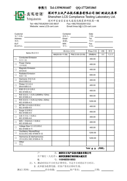
□
Power Clamp 功率辐射
□
Magnetic Emission 磁场辐射
□
Radiated Emission 辐射干扰
□ Harmonic 谐波电流
EN 61000-3-2
□ Flicker 电压波动
EN 61000-3-3
□ ESD 静电放电测试
IEC 61000-4-2
□ R/S 辐射抗干扰测试(80MHz-1GHz)
李秀兰 Tel:13590301687 QQ:1772051865
深圳市立讯产品技术服务有限公司 EMC 测试记录单
Shenzhen LCS Compliance Testing Laboratory Ltd.
深圳市宝安区宝安大道通达路星源科技园一楼
Tel:+86(755)82591330-8837 Website:
Total 合 计 (RMB)
户
名:深圳市立讯产品技术服务有限公司
开户银行(人民币):深圳发展银行深圳南头城支行
帐
号:11004855019503
注:1、测试时间以半小时为计费单位,不足半小时的以半小时计;
2、此单据为收费:
客户签名:
日期:
59rmbh小时人民币conductedemission传导干扰45000powerclamp功率辐射45000magneticemission磁场辐射45000radiatedemission辐射干扰65000harmonic谐波电流en610003240000flicker电压波动en610003340000esd静电放电测试iec610004240000辐射抗干扰测试80mhz1ghziec610004390000辐射抗干扰测试1ghz2ghziec6100043120000eftb电快速脉冲群测试iec610004540000surge浪涌测试iec610004540000传导抗干扰测试iec610004640000工频磁场抗干扰测试iec610004840000voltagedips电压跌落测试iec6100041140000oscillatorywavesring振荡波测试iec61000412120000lnterharmonics谐间波测试iec61000413120000other其它total名
EMC测试报告审核模版

EMC测试报告编号:---测试目的受测设备配置1.受测设备型号对照2.受测设备及配套电源适配器/电源模块照片受测设备裸板正面图受测设备裸板背面图受测设备外观图受测设备电源适配器图片照片须需体现受测设备的信号端口类别,电源适配器照片要体现型号。
3.受测设备配置如无说明则需要在各测试项中提供测试配置照片。
2.2设备配置列例表表2.2.2 零部件配置表测试综述(测试结果汇总)性能判据判据A 在制造商、委托方或采购方规定的限值内性能正常;判据B 功能或性能暂时丧失或降低,但骚扰停止后能自行恢复,不需要操作者干预;判据C 功能或性能暂时丧失或降低,但需要操作者干预才能恢复;判据D 因设备硬件或软件损坏,或数据丢失而造成不能恢复的功能丧失或性能降低。
测试项目及测试方法(注明参照标准/使用仪器仪表)1辐射发射试验:1.1参照标准EN55022:2006+A1-2007进行测试,需要满足CLASS B的限值要求;注:若在3m法半电波暗室进行测试,对应限值可在10m的基础上得出:30~230MHz 40dB(µV/m)230~1000MHz 47dB(µV/m)。
1.2测试结果:1.2.1测试配置照片1.2.2测试图表可直接粘贴实验室的测试报告或图表。
备注:试验结果的判定,辐射发射的测试结果是否合格,以准峰值要满足相应的测试等级CLASS B为准,并有3dBµv的裕量。
2传导发射试验:2.1参照标准EN55022:2006+A1-2007对电源端口和电信端口进行测试,需要满足CLASS B的限值要求。
2.1.1电源端口的传导发射限值要求2.1.2电信端口的传导发射限值要求2.2测试结果:2.2.1测试配置照片2.2.2.1电源端口测试图表2.2.2.2 电信端口网口测试图标2.2.2.3电信端口语音测试图标可直接粘贴实验室的测试报告或图表。
备注:试验结果的判定,电源端口及电信端口的传导发射测试结果是否合格,以准峰值和平均值都要满足相应的测试等级CLASS B为准,并有3dBµv的裕量。
EMC基本测试报告格式及说明
随着电气电子技术的发展,家用电器产品日益普及和电子化,广播电视、邮电通讯和计算机网络的日益发达,电磁环境日益复杂和恶化,使得电气电子产品的电磁兼容性(EMC电磁干扰EMI 与电磁抗EMS)问题也受到各国政府和生产企业的日益重视。
欧共体政府规定,从1996年1月1起,所有电气电子产品必须通过EMC认证,加贴CE认证标志后才能在欧共体市场上销售。
此举在世界上引起广泛影响,各国政府纷纷采取措施,对电气电子产品的RMC性能实行强制性管理。
根据欧盟的电磁兼容(EMC)指令2004/108/EC,所有在欧盟市场销售的电子电气产品必须在其对其他产品的干扰性及对外来影响的抗干扰性方面严格符合欧盟法律要求。
检验记录产品名称NAME OF SAMPLE商标型号TRADE MARK & TYPE制造厂商MANUFACTURER委托单位CLIENT检验类别TEST SORT检验项目TEST ITEM 静电放电抗扰度、电快速瞬变脉冲群抗扰度、浪涌(冲击)抗扰度检验记录第3 页共页检验负责人:审核:批准:职务:年月日年月日年月日检验项目:浪涌(冲击)抗扰度试验依据标准:IEC 61000-4-5:2005 、企业要求产品名称:商标型号:样品编号:1#试验条件:温度:23 ℃,湿度:52 %RH,正常大气压。
电磁条件保证受试设备正常工作,并不影响试验结果。
EUT状态:试验前工作正常,试验中受试设备刷卡及RS485命令开锁正常,使受试设备处于正常工作状态。
试验等级:在受试设备的DC电源和信号线端口:正-负:电压峰值2kV,开路电压波形1.2/50µs(短路电流波形8/20µs),2Ω内阻正(或负)-地:电压峰值2kV,开路电压波形1.2/50µs(短路电流波形8/20µs),12Ω内阻信号线对线:电压峰值2kV,开路电压波形1.2/50µs(短路电流波形8/20µs),15Ω内阻信号线对地:电压峰值2kV,开路电压波形1.2/50µs(短路电流波形8/20µs),15Ω内阻要求符合性能判据B。
EMC测试指标及测试方法介绍(免费)
EMC测试指标及测试方法介绍研发中心产品认证部深圳市同洲电子股份有限公司2011年9月17日EMC简介EMC(Electromagnetic Compatibility )定义:在同一电磁环境中,设备能够不因为其它设备的干扰影响正常工作,同时也不对其它设备产生影响工作的干扰。
EMC = EMI + EMS电磁干扰抗电磁干扰电磁兼容EMI测试指标q辐射骚扰场强q电源端骚扰电压q天线端骚扰电压q骚扰功率q射频输出端有用信号和骚扰信号电平q辐射骚扰功率q谐波电流q电压波动与闪烁EMS测试指标q天线输入端差模电压抗干扰S1 q射频电压抗干扰S2aq天线输入端射频电流抗干扰S2b q辐射抗干扰S3q脉冲调制波抗干扰S5q静电放电ESDq电快速瞬变脉冲群EFTEMC测试指标及测试方法介绍第一部分:电磁干扰EMIEMI --辐射骚扰场强1.简要说明测量对象主要是广播接收机。
设备的辐射过高必会污染电磁环境。
辐射骚扰场强在开阔场上或电波暗室中进行,测量距离为3m、5m或10m 。
(一般按3m测试,下述内容按3m测试描述)对有同轴天线输入的广播接收机,通过电缆馈入有用信号,而不是采用天线辐射接收。
EMI --辐射骚扰场强2.测试方法装置:EMI测试接收机、测试天线、转台/天线杆定位控制器等。
对于常见的台式设备,测量时将其置于80cm高的非金属转台上,测试天线的测试基准点与被测设备的假想辐射中心(一般也是其几何中心)的水平距离即测试距离为3m。
在测试过程中,转台在0~360°范围内旋转,而测试天线在1~4m(水平极化)和2~4m(垂直极化)范围内升降,并分别在天线水平极化和垂直极化状态下进行,以获得最大骚扰值。
(做FCC测试时,天线升降范围在水平及垂直均为1~4m)EMI --辐射骚扰场强3.测试方法示意图EMI --辐射骚扰场强4.指标限值EMI --辐射骚扰场强5.测试曲线示例010203040506070Level [dB 礦/m]30M 50M 70M 100M200M 300M 500M 700M 1GFrequency [Hz]Marker:168.78 MHz 33.48 dB 礦/mMES HLIM EN 55022 F Cl.B 3m Field Strength QP LimitEMI --辐射骚扰场强6.测试场景示例EMI --电源端骚扰电压1.简要说明电源端骚扰电压,适用于标准范围内所有可接入公用低压电网的设备。
EMC测试项目

EMC测试项目骚扰测量1、辐射杂散骚扰2、辐射连续骚扰3、传导连续骚扰抗扰度试验静电放电抗扰度辐射骚扰抗扰度电快速瞬变脉冲群抗扰度浪涌(冲击)抗扰度射频场感应的传导骚扰抗扰度电压暂降和短时中断抗扰度测试项标准与指标要求辐射杂散骚扰(测量距离3米)专用模式:GSM900MHz,ARFCN 62,BCCH 31;DCS1800MHz,ARFCN 700,BCCH 735;工作电压分别设置为4.2V和3.6V频率(MHz): 30 ~ 1000 < -36dBm1000 ~ 1710 < -30dBm1710 ~ 1785 < -30dBm1785 ~6000 < -30dBm空闲模式:GSM900MHz,ARFCN 62,BCCH 31;DCS1800MHz,ARFCN 700,BCCH 735;工作电压分别设置为4.2V和3.6V频率(MHz): 30 ~ 880 < -57dBm880 ~ 915 < -59dBm915 ~ 1000 < -57dBm1000 ~ 1710 < -47dBm1710 ~ 1785 < -53dBm1785 ~ 6000 < -47dBm辐射连续骚扰GSM900MHz,ARFCN 62, BCCH 31,工作在最大输出功率电平,EUT与充电器相连进行充电,带耳机工作.测量距离10米频率(MHz): 30 ~ 230 < 30dBuV/m230 ~ 1000 < 37dBuV/m传导连续骚扰交流电源端口传导连续骚扰GSM900MHz,ARFCN 62, BCCH 31,工作在最大输出功率电平,EUT与充电器相连进行充电,带耳机工作. 准峰值平均值频率(MHz): 0.15 ~ 0.5 66--56dBuV 56--46dBuV0.5 ~ 5 56dBuV 46dBuV5 ~ 30 60dBuV 50dBuV静电放电抗扰度静电放电抗扰度(分别在专用模式和空闲模式下测试)GSM900MHz,ARFCN 62,BCCH 31;DCS1800MHz,ARFCN 700,BCCH 735;分别在带耳机和不带耳机下工作带耳机:1.裸露的金属件,水平耦合板,垂直耦合板;试验条件:接触放电,每点测试次数10次.电平:+-2KV,+-4KV 工作正常2.机壳,接缝,按键,LED显示屏;试验条件:空气放电,每点测试次数10次.电平:+-2KV,+-4KV,+-8KV 工作正常不带耳机:1.裸露的金属件,水平耦合板,垂直耦合板;试验条件:接触放电,每点测试次数10次.电平:+-2KV,+-4KV 工作正常2.机壳,接缝,按键,LED显示屏;试验条件:空气放电,每点测试次数10次.电平:+-2KV,+-4KV,+-8KV 工作正常辐射骚扰抗扰度辐射骚扰抗扰度(分别在专用模式和空闲模式下测试)试验条件:1. 80MHz---1000MHz,水平极化,场强3V/m,用1KHz正弦信号进行80%的幅度调制. RXQUAL<3,EUT工作正常2. 80MHz---1000MHz,垂直极化,场强3V/m,用1KHz正弦信号进行80%的幅度调制. RXQUAL<3,EUT工作正常电快速瞬变脉冲群抗扰度交流电源端口电快速瞬变脉冲群抗扰度(分别在专用模式和空闲模式下测试)试验条件:电压+-2KV ,持续时间: 1分钟交流电源零线工作正常交流电源火线工作正常交流电源零线,火线工作正常浪涌(冲击)抗扰度交流电源端口浪涌(冲击)抗扰度(分别在专用模式和空闲模式下测试)交流电源端口: 火线---->零线,电压+-0.5KV 每一极性5个脉冲,间隔1分钟工作正常射频场感应的传导骚扰抗扰度交流电源端口射频场感应的传导骚扰抗扰度试验条件:3V, 0.15--80MHz 分别在带耳机和不带耳机下测试工作正常直流电源端口射频场感应的传导骚扰抗扰度试验条件:3V, 0.15--80MHz 分别在带耳几机和不带耳机下测试工作正常电压暂降和短时中断抗扰度交流电源端口电压暂降和短时中断抗扰度(分别在专用模式和空闲模式下测试)电压降低30%,持续时间10ms 工作正常电压降低60%,持续时间100ms 工作正常电压降低95%以上,持续时间5000ms 工作正常Description StandardRadiation spurious emission1.1Traffic mode:GSM900MHz,ARFCN 62,BCCH 31;DCS1800MHz,ARFCN 700,BCCH 735;set voltage as 4.2V and 3.6VFrequency(MHz): 30 ~ 1000 < -36dBm1000 ~ 1710 < -30dBm1710 ~ 1785 < -30dBm1785 ~6000 < -30dBm1.2 Idle mode:GSM900MHz,ARFCN 62,BCCH 31;DCS1800MHz,ARFCN 700,BCCH 735;set voltage as 4.2V and 3.6VFrequency(MHz): 30 ~ 880 < -57dBm880 ~ 915 < -59dBm915 ~ 1000 < -57dBm1000 ~ 1710 < -47dBm1710 ~ 1785 < -53dBm1785 ~ 6000 < -47dBmRadiation continuous emissionGSM900MHz,ARFCN 62, BCCH 31,working in max output power,EUT connect with charger and charging,with handfree.Test distance 10m.Frequency(MHz): 30 ~ 230 < 30dBuV/m230 ~ 1000 < 37dBuV/mConduction continuous emissionAC power port conduction continuous emissionGSM900MHz,ARFCN 62, BCCH 31,working in max output power,EUT connect with charger and charging,with handfree. 准峰值AverageFrequency(MHz): 0.15 ~ 0.5 66--56dBuV 56--46dBuV0.5 ~ 5 56dBuV 46dBuV5 ~ 30 60dBuV 50dBuVImmunity to interference of static dischargeImmunity to interference of static discharge(test in traffic mode and idle mode)GSM900MHz,ARFCN 62,BCCH 31;DCS1800MHz,ARFCN 700,BCCH 735;working with handfree and without handfreeWith handfree:1.exposed metal,plane coupling board,vertical coupling board;test condition:contact discharge,test 10 times on every test nod. V oltage:+-2KV,+-4KV funication normal2.Cover,seam,keystroke,LED display;Test condition:air discharge,test 10 times on every test nod. V oltage: +-2KV,+-4KV,+-8KV funication normalWithout handfree:1.exposed metal,plane coupling board,vertical coupling board;test condition: contact discharge,test 10 times on every nod.voltage: +-2KV,+-4KV funication normal2.Cover,seam,keystroke,LED display;Test condition:air discharge,test 10 times on every test nod. V oltage: +-2KV,+-4KV,+-8KV funication normalImmunity to interference of radiation emission(test in traffic mode and idle mode)Test condition:1. 80MHz---1000MHz,horizontal polarization,field intensity 3V/m, 80% amplitude modulated with 1KHz sine signal. RXQUAL<3,funication normal2. 80MHz---1000MHz,horizontal polarization,field intensity 3V/m, 80% amplitude modulated with 1KHz sine signal. RXQUAL<3,funication normalElectric fast change pulse group immunity to interference电快速瞬变脉冲群抗扰度AC power port Electric fast change pulse group immunity to interference(traffic mode and idle mode)Test condition:voltage +-2KV ,duration: 1minAC power N line funication normalAC powr L line funication normalAC power N,L line funication normalSurge(Impact)immunity to interferenceAC power port Surge(Impact)immunity to interference(traffic mode and idle mode)AC power port: L---->N,voltage +-0.5KV 5 pulses every polarity,spacing 1 min. funication normalImmunity to interference of conduction emission inducted from radio frquency at AC power port Tes condition:3V, 0.15--80MHz test with handfree and without handfree funication normalImmunity to interferen of ceconduction emission inducted from radio frquency at DC power port Tes condition:3V, 0.15--80MHz test with handfree and without handfree funication normal Immunity to interference at voltage drop temporary and cut-off in short timeImmunity to interference at voltage drop temporary and cut-off in short time at AC power port(traffic mode and idle mode)V oltage drop down 30%,duration 10ms funication normalV oltage drop down 60%,duration 100ms funication normalV oltage drop down 95% above,duration 5000ms funication norm al。
EMC测试(TOP)2019-7-27
EMC测试1静电放电测试(ESD)2群脉冲测试(EFT)3雷击浪涌测试(Surge )EMC测试(IEC 61000系列标准)1静电放电测试(ESD测试)【接触放电】施打方式(Contact Discharge):包含直接接触(Direct Discharge)与间接(耦合)接触(Indirect Discharge)两种方式:直接接触放电方式(Direct Discharge):针对待测物上所有导电表面作测试,Discharge Tip请使用尖头,测试点在待测物本体上,放电枪直接在待测物上放电。
间接(耦合)放电方式(Indirect Discharge):针对待测物水平面(HCP)与垂直面(VCP)作间接(耦合)放电测试,Discharge Tip 请使用尖头,测试点在待测物本体上,放电枪直接在待测物上放电。
水平间接(耦合)接触放电:Horizontal Coupling将待测物置于塑料垫上,距HCP 10cm前,对HCP执行水平间接(耦合)接触放电,静电是以水平面间接耦合方式,传导至待测物。
EUT 四面都需要做测试。
垂直间接(耦合)接触放电:Vertical Coupling将待测物置于塑料垫上,距VCP 前10cm, 对VCP边线线中心点作垂直间接(耦合)接触放电,静电是以垂直面间接耦合方式,传导至待测物。
EUT 四面都需要做测试。
【空间(空气)放电】施打方式(Air Discharge):针对放电枪无法直接、间接接触(Contact)放电的表面或缝隙,则执行Air Discharge。
于电压到达要求值时将Discharge按钮按下,将Discharge Tip(使用圆头)迅速接近测试点(不得破坏待测物),接触后离开,放开按钮,等待电压指示再次达到要求值时,再以相同方式操作,反复执行直到测试完成。
方法:1.按以下参数逐步设置好“静电放电测试仪器”工作步骤:直接接触放电:±4KV(测试金属部位、可接触的金属部件);水平间接(耦合)接触放电:±4KV垂直间接(耦合)接触放电:±4KV空间(空气)放电:±8KV测试电压极性:先打正电压,再打负电压。
EMC测试报告

EMC测试报告EMC TEST REPORTReport No: TS12060041-EME Model No: RPI-H3, RPI-H2.5 Issued Date: Jan. 30, 2013Applicant: Address: DELTA ELECTRONICS INC.39 Sec. 2, Huandong Road, Shanhua Dist., Tainan city 74144, TaiwanTest Methods/ Standards: EN 301 489-17 V2.1.1/EN 301 489-1 V1.9.2EN 61000-6-3: 2007+A1: 2011 /EN 61000-6-1: 2007EN 61000-6-4: 2007+A1: 2011/EN 61000-6-2: 2005EN 61000-3-2: 2006+A1: 2009 +A2: 2009EN 61000-3-3: 2008IEC 61000-4-2: 2008/ EN 61000-4-2: 2009ICE 61000-4-3: 2010/ EN 61000-4-3:2006+A1:2008+A2:2010 ICE 61000-4-4 :2012/EN 61000-4-4: 2012IEC 61000-4-5: 2005/ EN 61000-4-5: 2006IEC 61000-4-6: 2008/ EN 61000-4-6: 2009IEC 61000-4-8: 2009/ EN 61000-4-8: 2010IEC 61000-4-11 :2004/EN 61000-4-11: 2004IEC 61000-4-16: 2011IEC 61000-4-18: 2011IEC 61000-4-29: 2000Test By: Intertek Testing Services Taiwan Ltd.,Hsinchu LaboratoryNo. 11, Lane 275, Ko-Nan 1 Street, Chia-Tung Li,Shiang-Shan District, Hsinchu City, TaiwanIt may be duplicated completely for legal use with the allowance of the applicant. It shall not be reproduced except in full, without the written approval of Intertek Laboratory. The test result(s) in this report only applies to the tested sample(s). The test report was prepared by: Sign on FileCandy Liu / AssistantThese measurements were taken by:Sign on FileAnson Lee / EngineerName Arthur TsaiTitle Senior EngineerTable of Contents1. General Information (6)1.1 Identification of the EUT (6)1.2 Additional information about the EUT (7)2. Test Summary (8)2.1 Test requirements (8)3. Test Specifications (11)3.1 Standards (11)3.2 Test Facility accreditation (12)3.3 Classification of ITE (12)3.4 External port (13)3.5 Performance verification (13)3.6 Mode of operation during the test (13)3.7 Peripheral equipment (14)4. Conducted Emission Test (15)4.1 Test arrangement (15)4.2 Photographs of the test arrangement (15)4.3 Test Procedures (15)4.4 Test Equipment (16)4.5 Conducted Emission Limit for AC mains port (16) 4.6 Uncertainty of Conducted Emission (16)4.7 Test Result: Pass (17)5. Radiated Emission Test (19)5.1 Test arrangement (19)5.2 Photographs of the test arrangement (19)5.3 Test Procedures (19)5.4 Test Equipment (20)5.5 Radiated Emission Limit (20)5.2.1 Test Procedure from 1 GHz to 6 GHz (23)5.2.2 Test Equipment (24)5.2.3 Radiated Emission Limit (24)5.2.4 Uncertainty of Radiated Emission (24)5.2.5 Radiated Emission Test Data from 1 GHz to 6 GHz (25)6. Harmonic Test (26)6.1 Test arrangement (26)6.2 Test Procedure & classification (26)6.3 Classification (26)6.4 Test Equipment (27)6.5 Uncertainty of Harmonic (27)6.6 Test Result (28)7. V oltage Fluctuations-Flicker Test (29)7.1 Test arrangement (29)7.2 Test Procedure (29)7.3 Test Equipment (30)7.4 Uncertainty of Flicker (30)7.5 Test result (30)8. Electrostatic Discharge Immunity Test (31)8.1 Test arrangement (31)8.2 Photographs of the test arrangement (31)8.3 Test Procedure (31)8.4 Test Specification (32)8.5 Test Equipment (33)8.6 Requirement (33)8.7 Test Result: Pass (34)9. Radiated Susceptibility Immunity Test (38)9.1 test arrangement (38)9.2 Photographs of the test arrangement (38)9.3 Test Procedure (38)9.7 Generation of the Electromagnetic Field (40)9.8 Test Results: Pass (41)10. Electrical Fast Transient/Burst Immunity Test (42)10.1 Test arrangement (for Main power) (42)10.2 Test arrangement (for DC port) (42)10.3 Test arrangement (for RS-485&RJ45port) (42)10.2 Photographs of the test arrangement (43)10.3 Test procedure (43)10.4 Test Specification (43)10.5 Test Equipment (44)10.6 Requirement (44)10.7 Test Results (45)11. Surge Immunity Test (46)11.1 Test arrangement (AC side) (46)11.2 Test arrangement (DC side) (46)11.3 Test arrangement (Signal port) (47)11.2 Photographs of the test arrangement (47)11.3 Test procedure (47)11.4 Test Specification (48)11.5 Test Equipment (48)11.6 Requirement (49)11.7 Test Results: Pass (50)11.7.1 Main power port (50)11.7.2 DC power port & Signal port (50)11.7.3 Signal port (50)12. Immunity to Conducted Disturbances, Inducted by Radio-Frequency Fields (51) 12.1 Test arrangement (51)12.2 Photographs of the test arrangement (51)12.3 Test procedure (51)12.7 Generation and Calibration of the Disturbance Signal (53)12.8 Test Results: Pass (54)13. Power Frequency Magnetic Field Immunity Test (55)13.1 Test arrangement (55)13.2 Photographs of the test arrangement (55)13.3 Test procedure (55)13.4 Test Specification (56)13.5 Test Equipment (56)13.6 Requirement (57)13.7 Test Result: Pass (57)14. V oltage Dips, Short Interruptions and V oltage Variations Immunity Test (58)14.1 Test arrangement (58)14.2 Photographs of the test arrangement (58)14.3 Test procedure (58)14.3 Test Specification (59)14.4 Test Equipment (59)14.5 Requirement (60)14.6 Test Result: Pass (61)15. Test for immunity to conducted, common mode disturbances in the frequency range (62) 15.1 Test arrangement (62)15.2 Photographs of the test arrangement (62)15.3 Test procedure (62)15.4 Test Specification (63)15.5 Test Equipment (63)15.6 Requirement (64)15.7 Test Results: Pass (64)16. Damped oscillatory wave test (65)16.1 Test arrangement (65)16.2 Photographs of the test arrangement (65)16.3 Test procedure (65)16.4 Test Specification (66)16.5 Test Equipment (66)17. V oltage dips, short interruptions and voltage variations on d.c. input power port immunity tests (70) 17.1 Test arrangement (70)17.2 Photographs of the test arrangement (70)17.3 Test procedure (70)17.4 Test Specification (71)17.5 Test Equipment (71)17.6 Requirement (72)17.7 Test Results: Pass (73)Appendix A1: External photo of EUT (74)Appendix B1: Conducted Emission Test Set-up (78)Appendix B2: Radiated Emission Test Set-up (79)Appendix B3: Harmonic and Flick Test Set-up (81)Appendix B4: Electrostatic Discharge (ESD) Test Set-up (82)Appendix B5: Radiated Susceptibility (RS) Test Set-up (83)Appendix B6: Electrical fast transient / burst (EFT) Test Set-up (84)Appendix B7: Surge Test Set-up (86)Appendix B8: Conducted disturbances (CS) Test Set-up (88)Appendix B9: Power frequency magnetic field (PFM) Test Set-up (89)Appendix B10: V oltage Dips Test Set-up (90)Appendix B11: Conducted, common mode disturbances in DC~150kHz Test Set-up (91)Appendix B12: Damped oscillatory wave test Set-up (92)Appendix B13: D.C Dip test set-up (93)1. General Information1.1 Identification of the EUTInverterProduct: PVModel No.: RPI-H3DC Input: 125~630 Vdc, Max 10 ARated Power:AC Output: 230 Vac, 50Hz/60Hz, 14.3 A, 3000V AMax. output power: 3000V AMax. output current: 14.3 APower Cord: 2C wires 1.8 meters cable1-Phase/3-Wire 3 meter cableSample receiving date: May. 30, 2012Sample condition: WorkableTesting date: May. 30, 2012 ~ Jan. 22, 2013Note 1: This report is for the exclusive use of Intertek's Client and is provided pursuant to the agreement between Intertek and its Client. Intertek's responsibility and liabilityare limited to the terms and conditions of the agreement. Intertek assumes no liability to any party, other than to the Client in accordance with the agreement, forany loss, expense or damage occasioned by the use of this report. Only the Clientis authorized to permit copying or distribution of this report and then only in itsentirety. Any use of the Intertek name or one of its marks for the sale or advertisement of the tested material, product or service must first be approved inwriting by Intertek. The observations and test results in this report are relevantonly to the sample tested. This report by itself does not imply that the material,product, or service is or has ever been under an Intertek certification program. Note 2: The test report only allows to be revised within three years from its original issued date unless further standard or the requirement was noticed.Note 3: When determining the test conclusion,the Measurement Uncertainty of test has been considered.1.2 Additional information about the EUTThe customer confirmed the models listed as below were series model to model Sunmaster RPI-H3 (EUT), the difference between main model and series model are listed as below. Model Number DifferenceRPI-H3 Input: 125-630 Vdc, Max. 10 AOutput V oltage: 230 Vac, 50/ 60 Hz,Output power: 3 kV A nom,Output current: 14.3 A maxRPI-H2.5 Input: 125-500 Vdc, Max. 10 A Output V oltage: 230 Vac, 50/ 60 Hz Output power: 2.5 kV A nom, Output current: 12 A max2. Test Summary2.1 Test requirementsStandard Test Type Enclosure AC side DC side Signal portConducted Test ×√×× EN 61000-6-3: 2007+A1: 2011 Radiated Test √×××EN 61000-3-2: 2006 +A1: 2009 +A2: 2009Harmonic currentemissions×√××EN 61000-3-3: 2008 V oltage fluctuation &flicker×√××IEC 61000-4-2: 2008 ESD test √××× IEC 61000-4-3: 2010 RS test √××× IEC 61000-4-4: 2012 EFT test ×√** IEC 61000-4-5: 2005 Surge test ×√** IEC 61000-4-6: 2008 CS test ×√×× IEC 61000-4-8: 2009 Magnetic Field test √×××IEC 61000-4-11: 2004Dip test ×√××IEC 61000-4-16: 2011CS test inDC~150KHz×√××IEC 61000-4-18: 2011Damped Oscillatorytest×√××IEC 61000-4-29: 2000 D.C. Dip test ××√× √: Applicable ×: Not applicable *: Require by client2.2 Test resultsEmission (EN 61000-6-3: 2007+A1: 2011)Standard TestTypeResult Remarks Conducted Test PASS Meet the requirementsEN 61000-6-3: 2007+A1: 2011 Radiated Test PASS Meet the requirementsEN 61000-3-2: 2006+A1: 2009 +A2: 2009Harmonic current emissions PASS Meet the requirementsStandard Test Type Minimum Criteria Result Test JudgmentIEC 61000-4-2: 2008 ESD test Criterion B PASS Meets the requirements of Performance Criterion B IEC 61000-4-3: 2010 RS test Criterion A PASS Meets the requirements of Performance Criterion A IEC61000-4-4: 2012 EFT test Criterion B PASS Meets the requirements of Performance Criterion A IEC 61000-4-5: 2005 Surge test Criterion B PASS Meets the requirements of Performance Criterion B IEC 61000-4-6: 2008 CS test Criterion A PASS Meets the requirements of Performance Criterion A IEC 61000-4-8: 2009 Magnetic FieldtestCriterion A PASSMeets the requirements ofPerformance Criterion AIEC 61000-4-11: 2004 Dip test 1. 100% reduction-Performance Criterion B2. 60% reduction-Performance Criterion C3. 30% reduction- Performance Criterion C4.100% reduction- Performance Criterion C PASSMeets the requirements ofV oltage Dips:1. 100 % reduction-Performance Criterion A2. 60 % reduction-Performance Criterion B3. 30 % reduction-Performance Criterion B4. 100 % reduction-Performance Criterion BIEC 61000-4-16:2011 CS inDC~150kHz testCriterion A PASSMeets the requirements ofPerformance Criterion AIEC 61000-4-18:2011 DampedMeets the requirements ofPerformance Criterion BIEC 61000-4-29:2000 D.C Dip test 1. 100% reduction-Performance Criterion A2. 60% reduction-Performance Criterion C3. 30% reduction-Performance Criterion C4.100% reduction-Performance Criterion CPASSMeets the requirements ofV oltage Dips:1. 100 % reduction-Performance Criterion A2. 60 % reduction-Performance Criterion A3. 30 % reduction-Performance Criterion A4. 100 % reduction-Performance Criterion CRemark:The test items of IEC 61000-4-16、IEC 61000-4-18、IEC 61000-4-29 in this report were conducted by provided by Electronics Testing Center, Taiwan.(EN 301 489-1/-17)EmissionStandard Test Type Result RemarksConducted EmissionPASS Meet Class B LimitISNN/A N/AV oltage fluctuation & FlickerPASSMeet the requirementsImmunityStandard Test Type Performance CriteriaResult Test JudgmentEN 61000-4-2: 2009 ESD test Criterion B PASSMeets the requirements ofPerformance Criterion B EN61000-4-3 2006+A1:2008+A2:2010RS test Criterion A PASSMeets the requirements of Performance Criterion A EN 61000-4-4: 2004 +A1: 2010 EFT test Criterion B PASS Meets the requirements ofPerformance Criterion AEN 61000-4-5: 2006 Surge test Criterion B PASSMeets the requirements ofPerformance Criterion B EN 61000-4-6: 2009 CS test Criterion A PASSMeets the requirements ofPerformance Criterion A EN 61000-4-11: 2004Dip test1. 100 % reduction- Performance Criterion B2. 100 % reduction- Performance Criterion C3. 30 % reduction- Performance Criterion B4. 100 % reduction- Performance Criterion CPASSMeets the requirements of V oltage Dips: 1. 100 % reduction-Performance Criterion A 2. 100 % reduction-Performance Criterion A 3. 30 % reduction-Performance Criterion B 4. 100 % reduction-Performance Criterion B3. Test Specifications3.1 StandardsEN 61000-6-1: 2007 Electromagnetic compatibility - Generic immunity standard-For Residential, commercial and light industry environments.EN 61000-6-2: 2005Generic standards – Immunity for industrial environmentsEN 61000-6-3: 2007+A1: 2011 Generic standards –Emission standard for residential, commercial and light-industrial environmentsEN 61000-6-4: 2007+A1: 2011Generic standards – Emission standard for industrial environments.EN 301 489-17 V2.2.1 Electromagnetic compatibility and Radio spectrum Matters (ERM); ElectroMagnetic Compatibility (EMC) standard for radio equipment; Part 17: Specific conditions for Broadband Data Transmission SystemsEN 301 489-1 V1.9.2 Electromagnetic compatibility and Radio spectrum Matters (ERM); Electromagnetic Compatibility (EMC) standard for radio equipment and services; Part 1: Common technical requirementsEN 61000-3-2: 2006+A1: 2009 +A2: 2009 Electromagnetic compatibility ─ Part 3. Limits. Section 2. Limits for harmonic current emissions (equipment input current ≤ 16 A per phase) EN 61000-3-3: 2008 Electromagnetic compatibility ─ Part 3. Limits. Section 3. Limitation of voltage fluctuations and flicker in low-voltage supply systems for equipment with rated current ≤ 16 A3.2 Test Facility accreditationIntertek Testing Services Taiwan Ltd., Hsinchu Laboratory is accredited in respect of laboratory and the accreditation criterion is ISO/IEC 17025: 2005.Certification Bureau Code AccreditationCriteria TAF 0597 ISO/IEC17025AccreditationCertificate BSMI SL2-IS-E-0024SL2-IN-E-0024SL2-A1-E-0024SL2-R2-E-0024SL2-R1-E-0024SL2-L1-E-0024ISO/IEC 17025FCC 93910 Test facility list& NSA DataIC 2042D-1, 2042D-2 Test facility list& NSA DataSite Filling Code :VCCI R-1534C-1618T-1586Test facility list& NSA DataNote 1: Each certificate can refer to attachment certification.pdf.Note 2: Each certificate is within the valid calibration period.3.3 Classification of ITEITE is subdivided into two categories denoted class A ITE and class B ITE.Class B ITEClass B ITE is a category of apparatus which satisfies the class B ITE disturbance limits. Class B ITE is intended primarily for use in the domestic environment and may include: — equipment with no fixed place of use; for example, portable equipment powered by built-in batteries;— telecommunication terminal equipment powered by a telecommunication network; — personal computers and auxiliary connected equipment.NOTE: The domestic environment is an environment where the use of broadcast radio and television receivers may be expected within a distance of 10 m of the apparatus concerned. Class A ITEClass A ITE is a category of all other ITE which satisfies the class A ITE limits but not the class B ITE limits. Such equipment should not be restricted in its sale but the following warning shall be included in the instructions for use:WARNINGThis is a class A product. In a domestic environment this product may cause radio interference in which case the user may be required to take adequate measures.3.4 External portItems SpecificationsDC input port +,-AC mains output port 1-Phase/3-Wire (L, N, PE)WiFi Communication RS-485,RJ45,EPO&Note 1: EPO stands for “Emergency Power Off”.3.5 Performance verificationThe EUT has been monitored based on manufacturer’s specification; the performance fulfilled the requirements of standard.3.6 Mode of operation during the testThe input power port of EUT is connected with DC source, the output power port of EUT is connected with AC source and load. After EUT joining with AC source, when the output power of EUT raises, the AC source power will decline but not to zero. The margin of EUT raised power is the same as the margin of AC source declined power.3.7 Peripheral equipmentPeripheralsBrandModel No.Serial No.Description of cablelengthSymbolDC power Chroma 62150H-1000S N/AN/ABatteries frame YUASA&GS UXH90-12& GPL 121000 N/A N/AAC Converter APC AFC-33030J F311040038N/A Load N/A N/A N/A N/ANotebook PC IBM 2609 BA-ZHNHNRS 232 Cable 1meterRS232 to RS-485 Coverter*TryCon TRP-C06NARJ-45 UTP Cat.5.03 meterN/A* The equipment is supplied by client.4. Conducted Emission Test4.1 Test arrangement4.2 Photographs of the test arrangementPlease refer to the appendix B1 of the present report.4.3 Test Procedures1. The EUT is set up per the test arrangement and simulate the typical usage based on the user’s manual.2. Equipment designed for wall-mounted operation shall be tested as tabletop EUT. The orientation of the equipment shall be consistent with normal installation practice.3. The EUT are placed on a 1.0 meter(W)×1.5meter(L) and 0.8 meter in height wooden table and the EUT was adjusted to maintain a 0.4meter space from a vertical reference plane.4. The rear of the arrangement shall be flush with the back of the supporting tabletop unless that would not be possible or typical of normal use.5. The EUT is connected to power mains through a Artificial Mains Network (AMN), which provided 50 ohm coupling impedance for measuring instrument and the chassis ground was bounded to the horizontal ground plane of shielded room.6. The AMN is placed 0.8 meters from the EUT, All other units of the EUT and associated equipment shall be at least 0.8 m from the AMN .7. The excess power cable between the EUT and the AMN was bundled. All connecting cables of EUT and peripherals weremoved to find the maximum emission8. If the measuring receiver is connected to the voltage probe, the AMN shall be terminated with 50 ?.9. If any, measure the conducted emissions on each phase of power line of the EUT’s power source by using the test receiver.10. Sweep the signal from 150kHz to 30MHz by using the receiver with the maximum-Peak detector.11. If the peak emission level is lower than the average limit, then the emission valuespresented will be the peak value only. Otherwise, both of Q.P. and average values shall be measured. Reference ground plane 80 cm4.4 Test EquipmentEquipment Brand Model No. Serial No. CalibrationDateNextCalibrationEMI Receiver Rohde & Schwarz ESCS30 833364/0112012/06/15 2013/06/15200-A Four-LineV-NetworkRohde&schwarz ENV4200 848411/0122012/10/17 2013/10/17Shield Room N/A N/A N/A N/A N/ANote: The above equipments are within the valid calibration period.4.5 Conducted Emission Limit for AC mains portFreq. MaximumRFLineV oltage (MHz) Class B (dBµV)Q.P.Ave.0.15~0.50 66-56 56-460.50~5.00 56 465~30.00 60 50 4.6 Uncertainty of Conducted EmissionExpanded uncertainty (k=2) of conducted emission measurement is ± 2.786 dB.4.7 Test Result: PassPhase: Line Temperature: 24 ℃ Model No.: RPI-H3 Relative Humidity: 53 % Test Date: Nov. 21, 2012 Atmospheric Pressure: 1008 hPa Remark: N/AInput voltage: 500 V Vdc Output voltage:1-Phase/3-Wire (L, N, PE)Frequency range: 0.15 MHz to 30 MHzRemark:1. Corr. Factor (dB) = AMN Factor (dB) + Cable Loss (dB)2. Margin (dB) = Level (dBuV) – Limit (dBuV)Note: 1. Q.P. stands for Quasi-peak.2. Correction factor = cable loss + insertion loss of AMN.3. Margin = Level - Limit.Class B Q.P. Class B Ave.Phase: Neutral Temperature: 24 ℃ Model No.: RPI-H3 Relative Humidity: 53 % Test Date: Nov. 21, 2012 Atmospheric Pressure: 1008 hPa Remark: N/AInput voltage: 500 V Vdc Output voltage:1-Phase/3-Wire (L, N, PE)Frequency range: 0.15 MHz to 30 MHzRemark:1. Corr. Factor (dB) = AMN Factor (dB) + Cable Loss (dB)2. Margin (dB) = Level (dBuV) – Limit (dBuV)Note: 1. Q.P. stands for Quasi-peak.2. Correction factor = cable loss + insertion loss of AMN.3. Margin = Level - Limit.Class B Q.P. Class B Ave.5. Radiated Emission Test5.1 Test arrangement5.2 Photographs of the test arrangementPlease refer to the appendix B2 of the present report.5.3 Test Procedures1. The EUT is set up per the test arrangement and simulate the typical usage based on the user’s manual.2. Equipment designed for wall-mounted operation shall be tested as tabletop EUT. The orientation of the equipment shall be consistent with normal installation practice.3. Radiated testing is placed on a wooden table with a height of 0.8 meters above thereference ground plane and 10 meters away from the reference point of the receiver antenna in the open area test site.4. The table rotates 360 degrees to determine the position of the highest radiation. The antenna height is varied between one meter and four meters above reference ground plane to find the maximum value of the field strength.。
电磁兼容(EMC)测试报告

测试环形天线:环1 单项判定:P
附件2:9kHz-30MHz辐射电磁骚扰测试
测试环形天线:环2 单项判定:P
测试环形天线:环3 单项判定:P
第2页共3页
LAB-F-AAK0
报告编号:EMC- / 电磁兼容(EMC)测试报告 EMC Test Report
附件3:30M-300MHz辐射电磁骚扰测试
报告编号:EMC- /
电磁兼容(EMC)测试报告 EMC Test Report
测试申请单编 号NO.: 申请单位 Apply Dep: 测试单位Test Dept.:
样品描述 :
产品名称 Name: 产品型号 Product Model:
实验室地址 Address:
样品数量 Quantities:
环境温度Envionment Temperature:26℃
相对湿度Relative Humidity:60%
标准条款 测试项目 Test Item
测试仪器
Test Equipment
标准要求 Standard required
GB17743(4.3.1 )电源端子骚扰
电压
ESCI ENV216
电源端子L/N对外产生骚扰电压,频率范围为9KHz30MHz的电源端子骚扰电压限值见表2a。
Pቤተ መጻሕፍቲ ባይዱ
高频辐射电磁 CDN L-801 值见表3b,或按附录B规定的试验方法进行,每根电缆 符合 符合 符合 附件
骚扰
M2/M3 上测得共模端子电压不得超过标准中附B表B.1限值
3
GBT18595 周波跌落
EMS61000- 跌落电压30%,周期数10,相位180°,试验后灯应正 11K 常点亮
符合 符合 符合
CTI EMC测试能力

Wave shape:8/2us 100kA ( 可 以 IEC/EN 61000-4-5,GB/T 17626.5
外包)
Wave shape:1.2/50 8kV
Wave shape:8/20us 100kA (可以 IEC/EN 61000-4-5,GB/T 17626.5
外包)
Wave shape:1.2/50 8kV
公斤
、61000-6-3、61000-6-4, FCC 15、
18,GB 4824、GB13837、GB4343.1、
GB17743、GB 9254、GB 18655,GB
17799.3,GB17799.4,GR-1089-CORE, V-
3, EN300386,EN301489-1/3/17, ICES-
RF common mode on Telecom port
√
√
√
传导抗扰度(通讯端)
BCI
√
√
√
大电流注入
Voltage dips& interruption on Acport DC 0-300V 16A 16A
/
交流端电压跌落和中断
IEC/EN 61000-4-
29
Radiated immunity(鸿威3米) 辐射抗扰度
公斤
等
8kV,500kHz or 6kV,1000kHz IEC/EN 61000-4-4,GB/T 17626.4
5.5kV,1000kHz
IEC/EN 61000-4-4,GB/T 17626.4
5.5kV,1000kHz
IEC/EN 61000-4-4,GB/T 17626.4
Wave shape:1.2/50 8kV
EMC基本测试报告格式及说明

检验记录产品名称NAME OF SAMPLE商标型号TRADE MARK & TYPE制造厂商MANUFACTURER委托单位CLIENT检验类别TEST SORT检验项目TEST ITEM检验记录第2 页共页检验负责人:审核:批准:职务:年月日年月日年月日抗扰度试验判据说明:检验项目:浪涌(冲击)抗扰度试验依据标准:XXXXXXX产品名称:商标型号:样品编号:1#试验条件:温度:23 ℃,湿度:52 %RH,正常大气压。
电磁条件保证受试设备正常工作,并不影响试验结果。
EUT状态:试验前工作正常,试验中受试设备刷卡及RS485命令开锁正常,使受试设备处于正常工作状态。
试验等级:在受试设备的DC电源和信号线端口:正-负:电压峰值2kV,开路电压波形1.2/50µs(短路电流波形8/20µs),2Ω内阻正(或负)-地:电压峰值2kV,开路电压波形1.2/50µs(短路电流波形8/20µs),12Ω内阻信号线对线:电压峰值2kV,开路电压波形1.2/50µs(短路电流波形8/20µs),15Ω内阻信号线对地:电压峰值2kV,开路电压波形1.2/50µs(短路电流波形8/20µs),15Ω内阻要求符合性能判据B。
试验布置:严格按标准要求。
试验过程::浪涌(冲击)电压施加在EUT的DC电源和信号线端口,60秒钟一次,正、负极性各做5次。
试验电压由低等级增加到规定的试验等级,较低等级均应满足要求。
EUT表现:在整个试验过程中没有出现危险或不安全的后果,试验中及试验后,EUT工作正常,表现出抗扰能力。
符合性能判据 A 。
描述如下:受试设备在试验前正常工作,试验中及试验后EUT工作正常。
符合性能判据要求。
检验人:校核人:检验日期:校核日期:检验项目:静电放电抗扰度试验依据标准:IEC 61000-4-2:2001 、企业要求产品名称:商标型号:样品编号:1#试验条件:温度24 ℃,湿度:52 %RH ,正常大气压。
可靠度测试、化学测试、EMC测试项目一览表
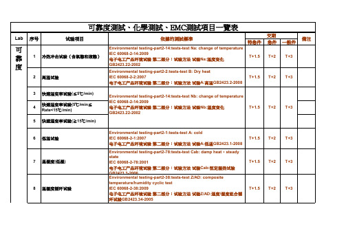
特急件急件一般件1Environmental testing-part2-14:tests-test Na: change of temperature IEC 60068-2-14:2009电子电工产品环境试验 第二部分:试验方法 试验Na:温度变化GB2423.22-2002T+1.5T+2T+32Environmental testing-part2-2:tests-test B: Dry heat IEC 60068-2-2:2007电子电工产品环境试验 第二部分:试验方法 试验A:高温GB2423.2-2008T+1.5T+2T+33456Environmental testing-part2-1:tests-test A: cold IEC 60068-2-1:2007电子电工产品环境试验 第二部分:试验方法 试验A:低温GB2423.1-2008T+1.5T+2T+37Environmental testing-part2-78:tests-test Cab: damp heat ,steady stateIEC 60068-2-78:2001电子电工产品环境试验 第二部分:试验方法 试验Cab:恒定湿热试验GB2423.3-2006T+1.5T+2T+38Environmental testing-part2-38:tests-test Z/AD: composite temperature/humidity cyclic test IEC 60068-2-38:2009电子电工产品环境试验 第二部分:试验方法 试验Z/AD:温度/湿度组合循环试验GB2423.34-2005T+1.5T+2T+3可靠度測試、化學測試、EMC測試項目一覽表Lab序号试验项目備注Environmental testing-part2-14:tests-test Nb: change of temperature IEC 60068-2-14:2009电子电工产品环境试验 第二部分:试验方法 试验Nb:温度变化GB2423.22-2002低温试验温湿度(低湿)依據的測試標準T+3T+1.5T+2交期快速温变率试验(≦5℃/min)快速温变率试验(5℃/min ≦Rate<15℃/min)快速温变率试验(≧15℃/min)可靠度高温试验冷热冲击试验(含氣態和液態)温湿度循环试验9Environmental testing-part2-78:tests-test Cab: damp heat ,steady stateIEC 60068-2-78:2001电子电工产品环境试验 第二部分:试验方法 试验Cab:恒定湿热试验GB2423.3-2006T+1.5T+2T+310測試方法參照客戶提供,測試規格由客戶提供T+1.5T+2T+311測試方法參照客戶提供,測試規格由客戶提供T+1.5T+2T+312產品標準或客戶提供之規格T+1.5T+2T+313IPC-6012B Section 3.3.6ANSI/J-STD-003B Section 4.2.1 1.52314JESD22-A108T+1.5T+2T+315JIS C5102 9.10 9.11T+1.5T+2T+316JIS C5102 9.17T+1.5T+2T+317JIS C0050 IEC68-2-2112318IEC 60884-1/UL817/JIS C 8306T+1.5T+2T+319產品標準或客戶提供之規格T+1.5T+2T+320測試方法參照客戶提供,測試規格由客戶提供T+1.5T+2T+321測試方法參照客戶提供,測試規格由客戶提供T+1.5T+2T+322測試方法參照客戶提供,測試規格由客戶提供T+1.5T+2T+3耐磨壽命測試觸控屏表面劃綫測試觸控屏表面點擊壽命測試大批量烧机/温湿度测试AC Power ON/OFF 测试DC Power ON/OFF 测试Power 老化試驗搖擺測試 電池壽命測試 PCB 耐熱強度測試分離器件壽命測試電解電容/固態電容壽命測試(加載)電解電容/固態電容壽命測試(空載)耐彎曲試驗23測試方法參照客戶提供,測試規格由客戶提供12324產品標準或客戶提供之規格T+1.5T+2T+325EIA-364-09C/EIA-364-13T+1.5T+2T+326產品標準或客戶提供之規格T+1.5T+2T+3沾錫天枰IEC 60068-2-69 2007 1.523錫爐JESD22-B102D1.52328MIL-STD 202G 210F / EIA-364-56C1.52329Environmental testing-part2-78:tests-test Cab: damp heat ,steady stateIEC 60068-2-78:2001电子电工产品环境试验 第二部分:试验方法 试验Cab:恒定湿热试验GB2423.3-2006T+1.5T+2T+330Basic environmental testing procedures part2: test Z/AM: combined cold/low air pressure tests IEC 60068-2-40:1983电子电工产品环境试验 第二部分:试验方法 试验Z/AM:低温/低气压综合试验 GB2423.25-2008Test Z/BM: combined dry heat/low air pressure tests IEC 60068-2-41:1983试验Z/BM:高温/低气压综合试验GB2423.26-2008Test M: low air pressure IEC 60068-2-13:1983试验M:低气压GB2423.21-2008T+1.5T+2T+331測試方法參照客戶提供,測試規格由客戶提供T+1.5T+2T+332Standard practice for operating fluorescent light apparatus for UV exposure of nonmetallic materials ASTM G 154-2006塑料实验室光源暴露试验方法第二部分:紫外荧光灯GB/T16422.3-1997T+1.5T+2T+327耐焊接熱測試元件表面溫度測試可焊性光碟機托盤進/出測試靜壓測試插拔耐久測試盐雾试验高空试验氙弧灯老化试验UV 老化试验33Environmental testing-part2 :test methods-test Cx: damp heat ,steady state(unsaturated pressurized vapour)IEC 60068-2-66:1994电子电工产品环境试验 第二部分:试验方法 试验Cx:未饱和高压蒸汽恒定湿热GB/T2423.40-1997T+1.5T+2T+334測試方法參照客戶提供,測試規格由客戶提供T+1.5T+2T+335隨機:ASTM D4728-06正弦:IEC60068-2-6:200712336IEC 60068-2-27:200812337ASTM D5276-98(reapproved2009)0.51338客戶提供12339GB/T4857.4-2008ASTM D642-22(reapproved2010)0.51340ISO 2759-2001GB/T 6545-19980.51341隨機:ASTM D4728-06正弦:IEC60068-2-6:200712342客戶提供12343客戶提供12344WI-043-016(檢測內部文件)0.51345GB/T 2792-19980.513振动(V8)客戶提供机械冲击(V8)客戶提供推拉力客戶提供235温度量测振动试验(V850)包装抗压跌落试验跌落G 值量测机械冲击试验纸板耐破强度大型产品或工业包装振动测试(V8)机柜大型产品或大工业包装跌落测试振动信号分析量测90度剥离试验180度剥离试验46高加速老化试验(HAST)跌落客戶提供倾斜客戶提供47測試方法參照客戶提供,測試規格由客戶提供T+1.5T+2T+348測試方法參照客戶提供,測試規格由客戶提供T+1.5T+2T+349測試方法參照客戶提供,測試規格由客戶提供T+1.5T+2T+31IEC62321/ US EPA 3052/ US EPA3050B/US EPA 6010C 1.5232IEC62321/ US EPA 3052/ EN 1122/US EPA 6010C 1.5233IEC62321/ US EPA 3052/ US EPA 6010C 1.5234IEC62321:2008/US EPA3060A/US EPA 7196A1.523523462347濕式消解法/US EPA 30522.53.54.58IEC 62321/US EPA3540C/ US EPA 3550C/US EPA 8270D 2349IEC 62321/US EPA3540C/ US EPA 3550C/US EPA 8270D2.53.54.510IEC 62321/US EPA3540C/ US EPA 3550C/GB/T 22048/US EPA 8270D23411 2.53.54.512 2.53.54.513BS EN 14582234元素成分分析铅/Pb 镉/Cd 汞/Hg 六价铬/Cr(VI)全氟辛烷磺酸及盐类/PFOS 全氟辛酸及盐类/PFOA 材料中金属元素含量分析四溴双酚A/TBBPA 六溴环十二烷/HBCDD 邻苯二甲酸酯/DOP 多溴联苯/PBBs多溴联苯醚/PBDEs 卤素F/Cl/BrUS EPA 3540C/ US EPA3550C/ IEC62321/US EPA 8270DIEC 62321/US EPA3540C/ US EPA 3550C/US EPA 8270D键盘/按键耐久性测试笔记本翻盖测试砂尘试验14IPC-TM-650/直接測試23415EN 71-3/ASTM F963 1.52316BS EN 1811/BS EN 1247217IEC 62321/US EPA3540C/ US EPA 3550C/US EPA 8270D 34518IEC 62321/US EPA3540C/ US EPA 3550C/US EPA 8270D 23419ZEK 01.22.53.54.5SCCP 2.5 3.5 4.5MCCP 2.5 3.5 4.521NIEA R315.01B/GB/Z 20155 2.5 3.5 4.51EN 550223452EN 550223453EN 550223454EN 61000-3-23455EN 61000-3-33456EN 61000-4-23457EN 61000-4-33458EN 61000-4-43459EN 61000-4-534510EN 61000-4-634511EN 61000-4-834512EN 61000-4-1134513EN 61000-4-1234520氯化石蜡/CPs 环硅氧烷富马酸二甲酯多环芳香烃/PAHs 镍释放量IEC 62321/US EPA3540C/ US EPA 3550C/US EPA 8270D 干电池中Cd/Pb/Hg 离子浓度(F-/Cl-/Br-/NO3-/NO2-/SO42-/PO43-)八大重金属11幅射干擾(3 m Chamber)EMC 幅射干擾(10 m Chamber)傳導干擾電流諧波測試電源電壓變動測試靜電放電測試電磁輻射耐受測試電源突波耐受測試雷擊波耐受測試傳導耐受測試電源磁場耐受測試電壓遂變短暫中斷及變動耐受測試震磁波耐受測試。
EMC检验的送检要求及资料说明 相关表格
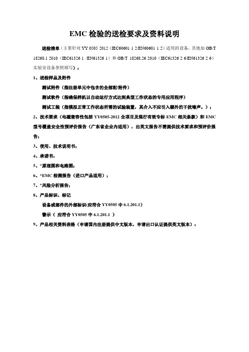
EMC检验的送检要求及资料说明送检清单(主要针对YY 0505-2012(IEC60601-1-2/EN60601-1-2)适用的设备,其他如GB/T 18268.1-2010(IEC61326-1 /EN61326-1)和GB/T 18268.26-2010(IEC61326-2-6/EN61326-2-6)实验室设备参照填写):1、送检样品及附件测试附件(指注册单元中包含的全部配/附件)测试软件(指确保样机以自动运行方式达到典型工作状态的专用应用程序)测试工装(指模拟正常工作状态所需的试验装置,其介入不应引入额外的干扰噪声。
);2、技术要求(电磁兼容性包括YY0505-2012全项目及现行有效专标EMC相关条款)和EMC 型号覆盖安全性预评价报告(广东省企业内适用),出英文报告不需提供技术要求和预评价报告;3、使用、技术说明书;4、承诺书;5、*原理图和电路图;6、*EMC检测报告(进口产品适用);7、*风险分析报告;8、产品标识、标记设备或部件的外部标识(应符合YY0505中6.1.201.1)警示(应符合YY0505中6.1.201.1 )9、产品相关资料表格(申请国内注册提供中文版本,申请出口认证提供英文版本):表1、基本性能(essential performance,保持残留风险在可接受限值内的必需的性能特征,见IEC60601-1 第三版)未识别基本性能有基本性能备注:一般需要通过风险分析,才能得出产品的基本性能。
如果没有经过风险分析,可以勾在“未识别基本性能”一栏。
表2、样品的预期使用场所或环境备注:A类、B类的信息由检测工程师根据产品的适用范围予以确认。
表3、检测报告首页信息确认(与合同是否一致)L+N+PE L+NL1+L2+L3+N+PE L1+L2+L3+N L1+L2+L3+PE由辅助设备供电是否是否是否是否是否是否是否是否表6、样品连接图备注:指样品的连接图,主要针对的是系统(设备与设备之间的连接示意图)。
EMC测试标准
频带
频率范围 (MHz) 限值 A,均值检波(dBµV) 限值 B,峰值检波(dBµV)
长波-调幅广播 0.15~0.3
64
93
0.3~0.53
84
113
中波-调幅广播
0.53~2
44
79
2~5.9
64
99
短波-调幅广播 5.9~6.2
39
65
6.2~30
59
85
通信频带
30~54
34
65
54~68
频带(MHz)
峰值检波
均值检波
BW
步长 驻留时间
BW
步长
驻留时间
0.15~30
9kHz
5kHz
50ms
9kHz
5kHz
50ms
>30
120kHz 50kHz
5ms
120kHz
50kHz
5ms
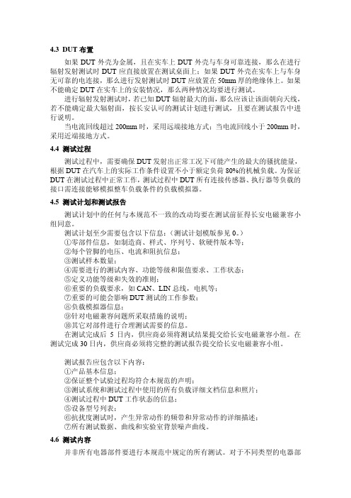
其它参数设置参照 CISPR 25。
5 辐射发射测试:RE01
图 2 辐射发射的试验布置
5.1 辐射发射测试布置
8辐射抗扰度测试:RI01
图 6 辐射抗扰度的试验布置图
8.1辐射抗扰度测试布置
电器部件辐射抗扰度的测试可参照 ISO11452-2 标准中的 ALSE 测试方法。电 器部件辐射抗扰度试验的一般布置如图 6 所示:
辐射抗扰度测试频率范围为 400MHz~2000MHz。信号频率大于 1000MHz 时, 天线中心应正对 DUT 中心,分别用水平和垂直方向测试。
如果 DUT 是电机或执行器,那么测试过程中需给 DUT 施加一定的机械负载, 不小于 DUT 额定负载的 80%。
7.2测试过程
PCB板EMC设计检查表

序号 项目评审要求评审结果 备注1 滤波电容靠近相关器件放置;检查低频、高频滤波电容的数量和位置是否合理2 相关器件尽可能放置在一起,缩短器件之间的走线3 数字、“模拟”器件分开放置,防止数字电路的干扰影响“模拟”器件4电容要靠近电源管脚放置,而且容值越小的电容越须要靠近电源管脚5 EMI 滤波器要靠近芯片电源的输入口 7 高速、中速、低速电路要分开8强电流、高电压、强辐射元器件远离弱电流、低电压、敏感元器件;9 模拟、数字、电源、保护电路要分开;10器件布局要求 对热敏感的元件(含液态介质电容、晶振)尽量远离大功率的元器件、散热器等热源。
1 将 PCB 分区为独立的模拟部分和数字部分,A/D 转换器等混合集成器件跨分区放置2 布线不能跨越数/模分割面之间的间隙3在电路板的所有层中,数字信号只能在电路板的数字部分布线;模拟信号只能在电路板的模拟部分布线4 数字与模拟电路实现模拟和数字电源分割,为防止地弹噪声,每个电源管脚都要增加去耦电容1 至少有一个连续完整的地平面控制阻抗和信号质量2 电源和地平面靠近放置3 叠层设计尽量避免两个信号层相邻,如果相邻加大两个信号层的间距4 避免两个电源平面相邻,特别是由于信号层铺电源而导致的电源平面相邻5 好的叠层能做到对阻抗的有效控制6 外层铺地7层叠设计要求多层板设计,有单独的电源和地平面1 金属连接器外壳是否“低阻抗”与机壳地PG 相连2“浮地”设计中,机壳地PG 与数字地GND 间距,尽可能达到80mil ,至少确保40mil3 PCB 板如果安装在完整的金属平面上(如1U 、2U 机箱),数子地GND 与金属螺钉孔(PG )之间,并联高压电容4接地设计要求 20H 原则:电源平面,是否相对地平面内缩,1 走线没有锐角和90度角2 走线是否遵循3W 原则(防止走线之间的串扰)3 重要信号线(如时钟、复位)是否有分流与保护走线(产生同轴线屏蔽效果)。
如果是多层板,尽可能走内电层4 走线须先经过TVS ,压敏电阻,放电管等防护器件5 须进行浪涌测试信号线有通流量要求,其线宽须保证15mil (1盎司)以上6 重要信号(复位、时钟)不要靠近板边或I/O 口附近7 关键信号线走线避免跨分割8 关键信号线走线避免“U ”型或“O ”型9 关键信号线走线是否人为的绕长10 相邻层布线方向互为垂直11 电源、地尽可能加粗,电阻、电容的FANOUT 线尽量平行器件长度方向打出 12 板上无多余过孔及浮空的布线13 关键信号线是否距离边沿和接口400mil 以上 14 相同功能的总线要并行走、中间不要夹叉其它信号 15 布线是否有可避免的STUB 线 16 晶振下面是否走线17 开关电源下面是否走线;18 跨分割的线是否进行了合适的处理 19 敏感的信号线是否采用包地处理 20走线要求接收和发送信号要分开走,不能互相夹叉1 浪涌抑制器件(TVS 管、压敏电阻)对应的信号走线是否在表层短且粗(一般10mil 以上);2 不同接口之间的走线要清晰,不要互相交叉3 接口线到所连接的保护和滤波器件要尽量短;4 接口线必须要经过保护或滤波器件再到信号接收芯片5 接口器件的固定孔是否接到保护地6 变压器、光耦等前后的地是否分开7 连接到机壳上的定位孔、扳手等没有直接接到信号地上8一般电源防雷保护器件的顺序是:压敏电阻、保险丝、抑制二极管、EMI 滤波器、电感或者共模电感,对于原理图缺失上面任意器件顺延布局9 一般对接口信号的保护器件的顺序是:ESD (TVS 管)、隔离变压器、共模电感、电容、电阻,对于原理图缺失上面任意器件顺延布局10隔离与保护要求严格按照原理图的顺序(要有判断原理图是否正确的能力)进行“一字型”布局11 电平变换芯片(如RS232)是否靠近连接器(如串口)放置12易受ESD 干扰的器件,如NMOS 、CMOS 器件等,是否已尽量远离易受ESD 干扰的区域(如单板的边缘区域)1 晶体、晶振和时钟分配器与相关的IC 器件要尽量靠近2 时钟电路的滤波器(尽量采用“∏”型滤波)要靠近时钟电路的电源输入管脚3 晶振和时钟分配器的输出是否串联一个22欧姆的电阻4 时钟分配器没用的输出管脚是否通过电阻接地;5 晶体、晶振和时钟分配器的布局要注意远离大功率的元器件、散热器等发热的器件6 晶振远离板边和接口器件是1inch 以上7 时钟电路的电源是否加宽或“铺铜”处理;8 超过1inch 的时钟线是否走内层9 需要走内层的时钟线是否在表层的走线<50mil 10 时钟信号“换层”时,是否为不同的地参考平面增加回流地过孔11 时钟线绝不允许跨分割 12 时钟线是否采用“立体”包地 13 时钟线与其它信号线的间距达到5W14晶振 、时钟晶振或时钟芯片的表层是否“局部”铺地,并通过多个过孔与地平面相连1 开关电源是否远离AD\DA 转换器、模拟器件、敏感器件、时钟器件;2 开关电源布局要紧凑,输入、输出要分开; 3严格按照原理图的要求进行布局,不要将开关电源的电容随意放置原则上每个电源管脚有一个小电容(0.1uF )、一个集成电路一个或多个10uf 大电容,可以根据具体情况进行增减4 电源平面是否比地平面内缩“20H ”(H 为电源和地平面的距离); 5电源平面是否比地平面内缩40mil ,并间隔150mil 打地过孔6 DC48V 的爬电间距是否为80mil 以上 7电源部分 AC220V 的爬电间距最少为300mil注:请在对应的[ ]中打“√”。
