Note_GTWorks3_C
VIAVI 16-lane CEM 插接器数据表说明书

Data SheetVIAVIXgig 16-lane CEM Interposer© 2023 VIAVI Solutions Inc.Product specifications and descriptions in this document are subject to change without notice.Patented as described at /patentsxgig-16-lane-cem-interposer-ds-snt-nse-ae 30193520 901 0123Contact Us+1 844 GO VIAVI (+1 844 468 4284)To reach the VIAVI office nearest you, visit /contactVIAVI SolutionsKit ContentsApplicationsWorking together with the VIAVI PCIe 5.0, Analyzer/Exerciser/Jammer platform, this Interposer enables debug and verification of new ICs, new system hardware designs, FPGA firmware, validation of system BIOS and software, and supports manufacturing test.The Xgig 16-lane, CEM slot Interposer is inserted into a 16-lane PCIe slot in the host system, and an endpoint card is installed into the top 16-lane slot connector creating the test data path. Cables connect the Interposer to the VIAVI protocol Analyzer/Exerciser/Jammer platform chassis.The photo to the right shows the Interposer connections to the Analyzer chassis, while the diagram indicates the signal path with DUT devices attached. Note that this Interposer requires an open DUT system chassis while in use.When operating in Analyzer mode, the DUT data is captured (tapped) from both the upstream and downstream signal paths as inputs to the Analyzer. When operating in Jammer mode, or Analyzer/Jammer mode, the Interposer data path is switched to route data into and out of the Xgig analysis system.VIAVI offers a variety of other Interposer types for connecting into many popular PCIe system applications, including other CEM, U.2, M.2, EDSFF , Flying-Lead and others.Ordering Information*CEM: Card Electro-Mechanical Specification (a PCIe spec)analysis toolsVIAVI PCle5Analysis SystemVIAVI Xgig 16-lane, CEM slot InterposerVIAVI Xgig5P-PCIe5-X16-CIC Interposer。
GT-Works3介绍

<项目>
<系统>
通过双击 创建新数据。
工程中的设置项均已按照 项 目、 系统和画面进行明确归类。每 一项内容都显示在画面上,便 于您快速选择所需设置项。仅 需双击“新建”即可创建新的 画面或注释。
<画面>
哪些功能最符合我的实际应用情况? 新图标简化功能选择,提高效率
用鼠标指向该图标, 可显示功能和操作 的介绍。
11
容易 自定义—非常简单。可扩大您的屏幕设计环境。
立即调用您的常用设置。 随心所欲地更改您的初始化设置
数字显示 图标
单击并放置即可
Before customization
不同程序员和设计者可根据其使 用习惯,自定义对象及数字的初 始化设置。可对经常使用的对象 进行预加载和预配置,以节省设 置对象所需的时间和工作量。 实例:自定义数字显示屏的初始 化设置 1)提前设置默认的字体大小、字 体类型和字体颜色。 2)单击图标放置对象后再对软元 件进行设置。
要点4 对话框(P.7) 用户友好的对话框和对象设置。
要点5 编辑器“画面编辑区”(P.8) 单击按钮,轻松完成在多个画面之间 的切换。设计者可利用各种便利高效 的显示功能。
5
简单 轻松完成高品质图形的拖曳,设置和操作一目了然。
所有的设置选项中-我该如何选择?
要点1 工作空间
设置项已按类别进行分类,便于您快速选择所需的设置项
一次修改多张图片或多个对象的设置参数。
利用批量修改和宽度/高度/坐标输入功能,轻松完成更改!
利用批量更改功能可一次性修改
所有的软元件、颜色、图片和通
道号。利用宽度/高度/坐标输入功
能,修改所选对象的尺寸大小。
通过输入宽度、高度和坐标等参
Mitsubishi Electric 工业机器人 MELFA RV-8CRL 产品介绍说明书

FACTORY AUTOMATIONMITSUBISHI ELECTRICINDUSTRIAL ROBOTMELFA RV-8CRLAllied Automation 800-214-0322Pursuing practical performanceUses an HK motor, the latest servomotor from Mitsubishi Electric. This allows improved torque characteristics, accuracy, and responsiveness while substantially reducing the size and weight. This adds up to much better robot performance and greater compactness.Continuous operation performanceLighter weight and improved heat release translate to improved continuous operation performance.Beltless coaxial drive mechanismA coaxial drive mechanism without belts is used for transmission to each axis (excluding the J4 and J5 axes).Simplification of the structure has improved transmission efficiency and reliability while also improving the ease of maintenance.No backup batteryThe use of the new HK motor eliminates the need for a battery to back up the robot’s internal encoder.This eliminates the cost and effort of regularreplacement as well as the risk of losing origin coordinates due to battery failure.A signal wire and air piping that can be used for gripper control, etc., are built in from the base to the forearm. Both ends of the signal wire haveuniversal D-sub connectors for use in various applications.Highest-in-class load capacityFeaturing a highest-in-class maximum load capacity of 8 kg, these robots boast a lighter-weight structure and reduced unit weight thanks to their simplified drive system and optimized arm structure, resulting in enhanced load capacity.Largest-in-class effective working areaOffers highest-in-class maximum reach radius of 931 mm. The use of a no-offset lower arm structure eliminating the J2-axis joint offset minimizes the interference region in the minimum turning radius and provides the largest-in-class effective working area.Standard IP65 supportComes standard with environmental resistance features allowing installation in plants and equipment where dust or oil mist is present.Can be used in oil mist environmentsJ6-axis motorJ3-axismotor J2-axismotorJ1-axismotor Slim & Compact Robot Offering a High Level of Utility and DesignSlim & compactA smooth, curved design complements the slim arm and compact joints. The external design is marked by minimalist, functional design.*Installation pitch:□160 mm (same as RV-4FR and 20% less than RV-7FR)Protrusionless structureIn addition to a slim, compact exterior and small robot base, its structure features minimal protrusions to the front, back, and sides, resulting in reduced interference with surroundings when the robot operates. This makes it suited to integration with automation cells and manufacturing equipment.1High-performance Controller Makes MELFA More IntelligentSafety monitoring functionWe will prepare a safety function compliant with international standards that simplifies risk assessments.Safety I/OExtends redundant safety I/O to 8 inputs and 4 outputs. Enablesdevelopment of various safety systems.Safety logic editingSimplifies development and operation of safety systems with safety logic editing.●Program editing and debugging ●Simulation function ●3D viewer●Monitoring function●Melfa RXM.ocx communication middlewareTrackingRobot tracks workpiece on conveyor, allowing transfer, alignment, and assembly without stopping conveyor.Additional axis controlBuild user mechanism controlling additional axes simultaneously with robot such as robot drive axis or turntable or separate from robot such as loader or positioning device. Control up to 8 axes. Our MELSERVO (MR-J4-B)servomotor can be used with additional axes.Robot mechanism thermal compensation functionMeasures the temperature of the robot arm and automatically corrects errors arising from thermal expansion of the arm.Callibration assistance functionAutomated calibration translates to simplification of installation of two-dimensional vision sensor and improvement of operational accuracy.Coordinated control of additional axesLinks robot and travel base for high-accuracy processing and assembly at specific speed.Also supports optional MELFA SmartPlusfunctional enhancement *1Comes standard with tracking and additional axis control PC software supporting everything from robot system designto installation, debugging, operation, and maintenance●Vision sensor configuration tool allows easy calibration of robot and camera ●Easy connection of robot and camera via Ethernet ●Easy control via robot program vision control commandSimultaneous controlmechanismsMechanism 1Mechanism 2Mechanism 3Up to 3Additional axesVision sensorSupports multiple conveyors simultaneously (up to 8)*1: Coming soonRobot controllerRobotLaser scannerTeaching boxRT ToolBox3Emergency stopArea sensorLamp2SpecificationsMechanical interfaceInternal wiring/pipingWiring/pipingInstallation dimensionsExternal dimensions/operating rangeMain Specifications15-pin D-sub AWG#24 (0.2mm ) ×15φ6 air joint (2)φ6 hose (2)Black Green Red Brown Yellow OrangeBlue Purple Gray Pink Light blue (Black)/Yellow (Black)/White (Black)/Blue 123456789101112131415123456789101112131415①②Baseφ6 air joint ①Tool wiring connector (15-pin D-sub)Tool wiring connector (15-pin D-sub)φ6 air joint ②Air pipe (2)φ6 air joint ①BaseUpper armForearmView A15-pin D-subForearmφ6 air joint ②Tool wiring (15)Tool wiring connectorRz25R z 25(Installation reference plane)(I n s t a l l a t i o n r e f e r e n c e p l a n e )1908080(160)978080(160)9797φ40h 8φ20H 7D6P .C.D .φ31.545°4-M5 thread depth 8φ5H7D84-φ9 installation hole*1: The wall mounting specifications are special specifications that restrict the operating range of the J1 axis.*2: “Maximum load capacity” is the maximum weight that can be loaded under the limitation of a mechanical interface having a downward attitude (within ±10° of the vertical position).View BP point operating areaP pointR 930.5-170°+170°R 219.315071R 150930.5930.51320.5244.4634.4930.585470390450100R 930.5+110°-110°Control point (R point)P point operating areaP point Downward limit of wristR 219.3102028020A71BWrist's downward singularity boundarySpace for the cable connectionMinimum: 310250256White 3External dimensions*2: Power supply voltage variability is within 10%.*3: Power capacity is recommended value.Note that power capacity does not include making current when turning on. Power capacity is an estimate.*4: Grounding work is to be performed by the customer.*5: Recommended USB cable (USB Type A, USB Mini-B Type): MR-J3USBCBL3M (Mitsubishi Electric), GT09-C30USB-5P (Mitsubishi Electric System & Service)*6: Mode select switch is to be provided by the customer.Controller specificationsStand-alone robot controllerRobot controller can be used for centralized control.430(30)30(3.5)37099.59642534045(40)(45)CR800-D4System configurationParallelinput-output interfaceinput-output unitExternal input-output cableCC-Link <Standard devices>GOT Pulse encoderServo Network R56TBR32TBsupport(SmartPlus)Machine cableController protection box<Functional options>Force sensor set MELFA-3D Vision⑨⑥RT ToolBox3 mini RT ToolBox3RT ToolBox3 Pro⑭②Encoder interfaceRobotRobot controller*1: Coming soon5OptionsController optionsFunctional optionsExpanded software functions*1: Coming soon6L (NA )09102ENG-BAll trademarks acknowledged.Printed December 2019HEAD OFFICE: TOKYO BLDG., 2-7-3 MARUNOUCHI,CHIYODA-KU, TOKYO 100-8310, JAPANMitsubishi Electric Corporation Nagoya Works is a factory certified for ISO 14001 (standards for environmental management systems) and ISO 9001(standards forquality assurance management systems)Global Partner. Local Friend.Allied Automation 800-214-0322。
MSI 迷你笔记本 SteelSeries Engine 使用手册说明书
[Troubleshooting] SteelSeries EngineThis document applies to all MSI Notebook which supports SteelSeries Engine.To know whether the product supports SteelSeries Engine or not, please visit MSI website and find the Overview page (Control) of your product.This document provides basic troubleshooting instructions for SteelSeries Engine and its common Q&A. Refer to the troubleshooting instructions if SteelSeries Engine doesn’t work properly, stops responding or crash unexpectedly. The common Q&A provides useful information when using SteelSeries Engine.Find the latest features, updates and fixes in SteelSeries Engine release note and follow the clean installation/update guide to perform the update.Outline1.Basic Troubleshooting (2)1.1.Confirm the Software Support (2)1.2.SteelSeries Engine Update (2)1.3.BIOS, EC Update & EC Reset (2)1.4.System Restore (2)1.5.Problem Report on Customer Support System (2)mon Q&A (3)1.Basic Troubleshooting1.1. Confirm the Software SupportMake sure that your notebook supports SteelSeries Engine by visiting theproduct Overview page (Control) on MSI website.1.2.SteelSeries Engine UpdateRefer to the general update guide to perform a clean installation of the latest SteelSeries Engine release on MSI website.1.3. BIOS, EC Update & EC ResetFollow the update guide to update the latest BIOS, EC firmware and do the EC reset. This may help re-initializing maltiple settings such as OC, keyboard and other power related setups.P.S. BOIS and EC update file can be found under product’s driver download page from MSI website.1.4. System RestoreIf the problem still remains after going through all steps above, try to restore the system back to the factory setting by using F3 recovery, Recovery Media created by MSI BurnRecovery tool or Windows 10 recovery function.1.5. Problem Report on Customer Support SystemIf the problem still remains after the system restore, create a ticket for theproblem on the online customer support system. Provide the systeminformation exported by using MSI Help Desk, detail problem symptomdescription and the clear problem replication steps.P.S. Provide the complete information (screen captures, recorded video, system information and the clear problem replication steps) can help shorten the troubleshooting time.mon Q&AQ: How to know if my notebook supports keyboard backlight adjustment?Visit the Specifications page of your product on MSI website, notebook which bundled with “Full-color backlighting SteelSe ries keyboard” supports keyboard backlight adjustment via SteelSeries Engine.*Note 1: Some old models support Keyboard Backlight Manager(KLM) for the keyboardbacklight adjustment function instead of SteelSeries Engine.*Note 2: 18“ series (e.g. GT80) do esn’t support the keyboard backlight adjustment eventhough it supports SteelSeries Engine, because it has only “Single color backlighting (red)SteelSeries keyboard”.Q: How can I enable the Audio mode for my keyboard backlight in SteelSeries Engine?When set the keyboard layout to Audio mode in SteelSeries Engine (SSE), the keyboard backlight only works when there is an audio signal playing (e.g. playing music, video…) from the speakers of the laptop with the volume 30% or above.*Note: If the speakers are muted or the audio is output from external devices via HDMI/DP connection, then the keyboard backlight won’t work.Q: Why does the keyboard backlight or the LED light on the front (e.g. GT72) isn’t lighting up?The keyboard backlight and the LED lights are controlled by the SteelSeriesEngine.If you have the self-installed system, make sure the SteelSeries Engine isinstalled properly.*Note: Visit the Utility download page of your product to download the latest SteelSeriesEngine.Q: How to avoid seeing blank options in SteelSeries Engine (SSE3) when running Windows 7 system with Chinese Tranditional or Simplified Chinese language?Update IE browser to IE 11 to avoid seeing the blank options in SteelSeriesEngine (SSE3).Q: What should I do if SteelSeries Engine stops working after performing the F3 system recovery?Refer to the update guide to re-install the latest SteelSeries Engine.Q: Why does the keyboard backlight keep flickering when playing games?This is a new feature “GAME SENSE” from SteelSeries Engine 3 which presents the game status (e.g. health and kills) of your character via keyboard backlight.*Note 1: Currently GAME SENSE supports DOTA2, CS:GO and MINECRAFT.*Note 2: Refer to the screen shot below for game settings of GAME SENSE.*Note 3: More SteelSeries Engine 3 introduction, please refer to the video tutorial.。
瑞士万通自动滴定仪说明书
■■■■■■■■■■■■■■■■■■■■■■
目录
目录
1 引言
1
1.1 Titrando 系统 ........................................................................ 1
1.2 仪器描述 ................................................................................. 2
3.4 3.4.1 3.4.2 3.4.3 3.4.4 3.4.5 3.4.6
连接 USB 设备 ..................................................................... 16 常规 ...................................................................................... 16 连接 USB 集线器 .................................................................. 16 连接打印机 .......................................................................... 17 连接天平 .............................................................................. 17 连接 PC 键盘(仅针对带 Touch Control 时的操作) ........... 19 连接条形码读取器 ............................................................... 19
Z550中文资料(Intel)中文数据手册「EasyDatasheet - 矽搜」

UNLESS O THERW ISE AGREED IN W RITING BY INTEL, THE INTEL PRO DUCTS ARE NO T DESIGNED NO R INTENDED FO R ANY APPLICATIO N IN W HICH THE FAILURE O F THE INTEL PRO DUCT CO ULD CREATE A SITUATIO N W HERE PERSO NAL INJURY O R DEATH MAY O CCUR.
Contact your local Inte l sale s office or your distributor to obtain the late st spe cifications and be fore placing your product orde r. Copie s of docum ents which have an orde r num be r and are re fere nce d in this docum en
三菱GT Works3使用详解PPT精选文档

11
双击 单击
单击 单击
12
12
2、GT Designer3的操作界面 由标题栏、菜单栏、工具栏、状态栏、折叠窗口、
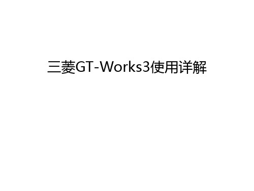
编辑窗口等组成。操作界面可以“视图”标 菜菜题 单单栏 栏项中更改。
工具栏 画面编辑窗口
折叠窗口
状态栏
13
13
➢ 修改画面显示比例。 ➢ 修改画面中图形对象的移动量。 ➢修修改改画栅面格背的景间色距、颜色。
4
4
二、GT Works3的主要组成部分 ➢ DataTransfer:读写全系列GOT的工程数据。 ➢ GT Designer3:创建人机界面工程。 ➢ GT Simulator3:仿真调试和监控PLC。 ➢ GT SoftGOT1000:电脑代替GOT1000运行监控画面。 ➢ GT SoftGOT2000:电脑代替GOT2000运行监控画面。
与GX Simulator2连接。 ➢ 再打开已编辑好的工程,就可以进行仿真联调。 ➢ 操作画面上的按钮,就可以观看梯形图程序运行和画
面显示的情况。
22
22
单击
23
23
单击
单击
24
24
25
25
2、GT Simulator3与PLC的连接 ➢ 用USB-SC-09数据线把电脑与PLC连接起来。 ➢ 使用GX Works2把编辑好的程序写入PLC。 ➢ 运行GT Simulator3,选择对应的模拟器。如:GT27。 ➢ 在“模拟”-“选项”菜单项目中进行通信设置,选择
5
5
DataTransfer
读写工程数据
6
6
GT Designer3
GOT
RS422/485 通讯
PLC
三菱GT-Works3使用详解教学文稿
工具栏 画面编辑窗口
折叠窗口
状态栏
12
➢ 修改画面显示比例。 ➢ 修改画面中图形对象的移动量。 ➢修修改改画栅面格背的景间色距、颜色。
13Байду номын сангаас
3、监控画面的创建 要求如下:
➢ 创建一个标题,名称:三相异步电机正反转控制。 ➢ 分别创建正转、正转点动、反转、反转点动、停止等
按钮只要基本设置即可
17
双击 设定对应的软元件, 显示数值位数、字体大小等。
18
16个指示灯分别 单击向下 由删D除鼠1辅0标的助移b直0到~线此b1处5位后控单击,箭头 制显然示后并拖点双动亮击修。改大小。 设定由D10.b0位控制显示 设定由D10.b0位控制点亮
19
三、GT Simulator3的使用 ➢ GT Simulator3与GX Simulator2的仿真联调 ➢ GT Simulator3与PLC的连接
与GX Simulator2连接。 ➢ 再打开已编辑好的工程,就可以进行仿真联调。 ➢ 操作画面上的按钮,就可以观看梯形图程序运行和画
面显示的情况。
21
单击
22
单击
单击
23
24
2、GT Simulator3与PLC的连接 ➢ 用USB-SC-09数据线把电脑与PLC连接起来。 ➢ 使用GX Works2把编辑好的程序写入PLC。 ➢ 运行GT Simulator3,选择对应的模拟器。如:GT27。 ➢ 在“模拟”-“选项”菜单项目中进行通信设置,选择
与CPU连接,连接方式为RS-232,选择机种: MELSEC-FX,选择通讯端口:电脑与PLC的连接串口。 打开已编辑好的工程,就可以监控PLC。 ➢ 操作画面上的按钮,就可以观看PLC运行和画面显示 的情况。
三菱GT Works3使用详解PPT幻灯片课件

13
修改画面显示比例。
修改画面中图形对象的移动量。 修修改改画栅面格背的景间色距、颜色。
上海理工大学电气工程学院
14
14
3、监控画面的创建 要求如下:
创建一个标题,名称:三相异步电机正反转控制。 分别创建正转、正转点动、反转、反转点动、停止等
五个按钮 。 分别创建电机正转、反转指示灯。 创建一个电机旋转的动画效果图。 创建一个输出域,显示数据寄存器D10的存储值。
PLC
8
GT Soft1000和GT Soft2000
最大画面尺寸 与显示器有关
上海理工大学电气工程学院
9
梯形图仿真
USB-SC-09 数据线
PLC
9
二、GT Designer3的使用 GT Designer3的启动 GT Designer3的操作界面 监控画面的创建
上海理工大学电气工程学院
执行“模拟启动/停止” 功能(启动GX Simulator2), 进行程序仿真。
运行GT Simulator3,选择对应的模拟器。如:GT27。
在“模拟”-“选项”菜单项目中进行通信设置,选择 与GX Simulator2连接。
再打开已编辑好的工程,就可以进行仿真联调。
操作画面上的按钮,就可以观看梯形图程序运行和画
上海理工大学电气工程学院
20
20
三、GT Simulator3的使用 GT Simulator3与GX Simulator2的仿真联调 GT Simulator3与PLC的连接
上海理工大学电气工程学院
21
21
1、GT Simulator3与GX Simulator2的仿真联调
打开用GX Works2编辑好的梯形图程序。
惠普彩色激光多功能打印机用户指南说明书
䐙ㄨㇸ≈
/videos/LaserJet /support/colorljM479MFP
HP Color LaserJet Pro M479 用户指南
版权与许可
© Copyright 2019 HP Development Company, L.P.
2 纸盘 .......................................................................................................................................................................................................... 17 简介 .......................................................................................................................................................................................... 17 将纸张装入纸盘 1 ................................................................................................................................................................ 18 简介 ..................................................................................................................................................................... 18 将纸张装入纸盘 1(多用途纸盘) ............................................................................................................ 18 纸盘 1 纸张方向 ............................................................................................................................................... 20 将纸张装入纸盘 2 ................................................................................................................................................................ 22 简介 ..................................................................................................................................................................... 22 将纸张装入纸盘 2 ........................................................................................................................................... 22 纸盘 2 纸张方向 ............................................................................................................................................... 24 将纸张装入纸盘 3 ................................................................................................................................................................ 26 简介 ..................................................................................................................................................................... 26Fra bibliotek商标说明
Pocket PC上网方式大全
Pocket PC上网方式大全(第2.2版)一, 直接上网方式由于Pocket PC主要是为便携使用的, 所以Pocket PC直接连接上网设备的情况一般很少采用. 而且设备厂商也没有提供相应的驱动程序软件, 微软Pocket PC 2002/2003操作系统也仅仅提供很少/有限的直接上网设备连接支持, 如: 没有提供Pocket PC版的PPPoE软件. 因此, 要使Pocket PC能够直接连接上网设备就一定需要采用第三方开发的软件和驱动程序. 但是, Pocket PC用户如果真的想这么使用的话, 不要担心找不到相应的软件和驱动程序.1. 同PCPocket PC应该可以象PC一样外接Modem/ISDN/GPS手机/CDMA1X手机/ADSL/Cable/FTTB直接上网.1) 串口Pocket PC连接串口外设(非PC)一般都需要空NULL Modem转接器, 即所谓的直接串(并)口互拷贝电缆. 如:eXpansys Null Modem Adaptor 9 Pin Female - 9 Pin Male/product.asp?code=NM-D9F-D9MeXpansys Null Modem Adaptor 9 Pin Male - 9 Pin Male/product.asp?code=3011213eXpansys 9 - 25 Pin Null Modem Adaptor/product.asp?code=P_NULLCABLEeXpansys 25 Pin Null Modem Cable - 3m Long/product.asp?code=DB25NULL-10a. 串口Modem微软的Pocket PC 2002/2003附带支持的Modem驱动程序, 如:贺氏Hayes compatible modem on Com1, 38400, 8 None 1b. 串口ISDN适配器同模拟Modem设置方式没有针对Pocket PC的驱动软件.c. 串口GPRS/CDMA1X Modem北京时代动力(TimesPower)数码科技有限公司/mobile/WM1080C.htm?CodeNo=00000019时代动力“随意猫”WM1080C GRPS高速调制解调器WM1080C GRPS高速调制解调器传输速率高达85.6kbps,支持Windows98/ME/2000/XP操作系统,并通过COM接口与PC 或主设备相连。
松下 可编程显示器GT32 技术手册

2019必修一 Welcome Unit Perioing

Let’s play
Let’s play
1. This __s_tr_a_t_e_g_y_ works in the lab but would not go over well in an office.
2. He's the president of a large international __o_r_g_a_n_i_za_t_i_o_n_. 3. The company needs to __im__p_r_o_v_e_ performance in all these
Pair work
Pair work
Share your ideas with your partner and discuss the questions.
1. What learning strategies do you and your partner share? 2. What is the best strategy for you to learn new words? How about
awkward curious
annoyed excited
frightened
awkward
anxious
excited
cuious
anxious confident
awkward curious
annoyed excited
frightened
annoyed
frightened
confident
Know yourself HYoowuryoleualrinkientgoslteyalren depends on what kyoinudr opferpseornsoanlityou are. If you like to talk, then it may be best to study in groups. If you are quiet, you may concentrate best on your own.
gxworks3st语言案例
文章标题:深度探析GXWorks3ST语言案例:从简到繁的编程艺术在现代工业自动化领域,PLC编程作为重要的控制手段,正日益受到广泛关注和应用。
而GXWorks3ST作为三菱电机控制器的编程软件,其语言案例更是备受瞩目。
本文将深入探讨GXWorks3ST语言案例,从简到繁地进行编程艺术的解析,希望能够为读者带来全面、深刻和灵活的理解。
1. GXWorks3ST语言案例概述GXWorks3ST语言案例是指在GXWorks3ST软件评台上的程序编写过程中,以不同的工业控制应用为背景,展示具体应用场景及其解决问题的方法。
这些案例旨在通过实际工程应用来展示程序设计的思路和方法,以及在实际生产中的运行效果。
在工业自动化领域,这些案例不仅是学习PLC编程的重要教材,更是工程师们解决实际问题的重要参考。
2. 从简到繁:GXWorks3ST语言案例的深度解析在GXWorks3ST语言案例中,我们可以从简到繁地学习编程的艺术。
通过简单的逻辑控制案例,例如灯光控制、电机启动停止等,我们可以了解基本的程序结构和指令使用。
通过复杂的传感器应用案例、温度控制案例等,我们能够学习更加深入的编程技巧和方法。
通过实际的工业生产线控制案例,我们可以深刻理解PLC编程在工业自动化中的重要性和应用广度。
3. GXWorks3ST语言案例的价值总结与回顾GXWorks3ST语言案例具有极大的教育和应用价值。
通过学习这些案例,可以帮助工程师们更好地掌握PLC编程的基本原理和技术,提高编程能力和解决实际问题的能力。
这些案例还能够激发工程师们的创造力,启发他们在实际工程中灵活运用编程知识解决问题。
4. 个人观点和理解作为一名工业自动化工程师,我深切理解GXWorks3ST语言案例对于个人职业发展的重要性。
通过不断学习和实践,我能够不断提高自己的编程能力,满足工业自动化领域不断变化的需求和挑战。
我也意识到在实际工作中,灵活运用所学的知识才是最重要的,只有将理论知识与实际案例相结合,才能取得更好的效果。
gx works3 ctu指令编程实例
文章标题:深度解析《gx works3 ctu指令编程实例》在工业自动化领域,PLC(可编程逻辑控制器)是起着至关重要作用的设备,而gx works3 ctu指令编程更是其中的核心内容之一。
本文将从多个角度对这一主题展开深入探讨,包括ctu指令的基本概念、应用实例、个人观点以及总结回顾。
1. CTU指令概述让我们来了解一下CTU指令的基本概念。
在gx works3中,CTU指令是一种用于计数的指令,它可以对输入信号进行计数,并根据设置的条件执行相应的动作。
CTU指令的功能十分强大,可以满足各种复杂的计数控制需求,是PLC编程中不可或缺的一部分。
CTU指令的编程也是相对复杂的,需要深入理解其工作原理和应用场景。
2. CTU指令编程实例接下来,让我们通过一个实际的应用实例来深入理解CTU指令的编程方法。
假设我们需要设计一个自动化生产线,其中需要对产品进行计数并根据计数结果执行相应的动作。
在这种场景下,CTU指令将发挥重要作用。
我们可以通过编写CTU指令来实现对产品计数的功能,并在达到指定计数值时触发相关的控制逻辑,如停止输送带或者进行下一步的加工动作。
通过这个实例,我们可以进一步理解CTU指令的灵活性和强大功能,以及在实际工程项目中的应用方式。
3. 个人观点和理解在个人观点和理解部分,我认为CTU指令编程在工业自动化领域具有非常重要的意义。
它不仅可以提高生产线的自动化程度,减少人工操作,还可以实现复杂的计数控制逻辑,满足多样化的生产需求。
学习和掌握CTU指令编程技术可以帮助工程师在实际项目中更加高效地运用PLC,提升工作效率。
4. 总结回顾让我们对本文进行总结回顾。
在本文中,我们深入探讨了CTU指令的基本概念和应用实例,了解了它在工业自动化中的重要性和广泛应用。
通过个人观点和理解的共享,将CTU指令编程与实际工程项目结合起来,展现了其强大的应用价值。
希望本文可以帮助读者更好地理解和应用CTU指令编程技术。
手把手教你学GT Desiger3触摸屏20130606
触摸屏的制作目录一GT介绍与安装二项目任务三GT的基本操作1新建工程2 工程的保存3 新建画面4 画面的放大及显示比例的设置5 按钮的制作及状态指示灯的制作6 权限的设置四项目实施1 简介画面的制作2 供料画面的制作3 机械手画面的制作4 分拣画面的制作一、GT介绍与安装三菱触摸屏编程软件GT Designer 3是用于三菱电机自动化GOT1000系列图形操作终端的画面设计软件,并且集成有GT Simulator3仿真软件,具有仿真模拟的功能。
GT Designer3 进行工程和画面创建、图形绘制、对象配置和设置、公共设置以及数据传输等的软件。
GT Simulator3 在PC机上模拟GOT运行的仿真软件。
软件的安装(1)获取软件安装包,安装文件(2)打开安装文件,图(1)下一步,双击,进行安装。
根据提示安装,直到显示要求输入公司名称,姓名,产品ID,如下图,公司名称,及姓名可随意输入,产品ID填写570-986818410 或570-996818410,接着一直根据提示点击“下一步”直到完成安装。
注:安装大约10分钟,左右,请勿操作电脑其他软件,程序。
二、项目任务制作设备的全线启动,停止,复位、状态指示灯及各单元的动作运行按钮等。
触摸屏共分为四个页面,分别是设备简介,供料单元,机械手单元及分拣单元。
各页面的完成效果图,如下图1-41、设备简介页面图22、供料单元页面图3 3机械手单元页面图44、分拣单元页面图5三、GT的基本操作1 新建工程(1)在电脑桌面双击,出现工程选择窗口,如下图图(6)点击新建,(也可菜单栏中“工程”中的“新建”)弹出新建工程向导,如下图图(7)(2)点击下一步,进行机种选择图(8)(3)根据实际情况选择几种,选择GT10系列中的“GT10**-Q(320X240)”,选择好点击下一步,切换到一下页面图(9)(4)此页无需设置,继续点击下一步,根据实际设置如下图制造商为三菱电机,机种为MELSEC-FX图(10)(5)接下所有页面无需设置,依次点击下一步至一下页面图(11)点击“结束”,进入触摸屏制作画面2、工程的保存(1)点击菜单栏中的工程,出现一下子菜单图(12)(2)第一次点击子菜单中的保存时,会跳出“另存为”页面,如下图图(13)(3)设置“保存路径”,工作区名及工程名必须填,可任意给定,后点击“保存”,完成对工程的保存。
- 1、下载文档前请自行甄别文档内容的完整性,平台不提供额外的编辑、内容补充、找答案等附加服务。
- 2、"仅部分预览"的文档,不可在线预览部分如存在完整性等问题,可反馈申请退款(可完整预览的文档不适用该条件!)。
- 3、如文档侵犯您的权益,请联系客服反馈,我们会尽快为您处理(人工客服工作时间:9:00-18:30)。
使用安全性对策软件时的MELSOFT GT Works3安装手册
----------------------------------------------------------------------------------------------------
·安装步骤
① 请卸载病毒安全防护ZERO。
② 重新启动计算机。
③ 请插入MELSOFTFT GT Works3之后,请根据需要重新安装病毒安全防护ZERO。
以上
使用以下其他公司制造的安全性对策软件时,MELSOFT GT Works3有时无法正常结束。
·病毒安全防护ZERO(SOURCENEXT制)
1.原因
可能是防病毒软件及安全性对策软件使用的驱动程序的动作,与DVD-ROM等外部记录媒体使用的驱动程序的动作
发生冲突,对MELSOFT GT Works3安装产生影响。
2.处理方法
为正常安装MELSOFT GT Works3,请按照以下步骤进行安装。
(请注意):
若将安全性对策软件临时设置为无效的状态或临时设置为已卸载的状态,会增加计算机感染病毒的风险。
请与网络管理员商谈之后,按照以下安装步骤执行。
2-1. 使用病毒安全防护ZERO(SOURCENEXT制)时
