银河文明3种族建造战斗解说视频教程
刺客信条3——家园建设攻略
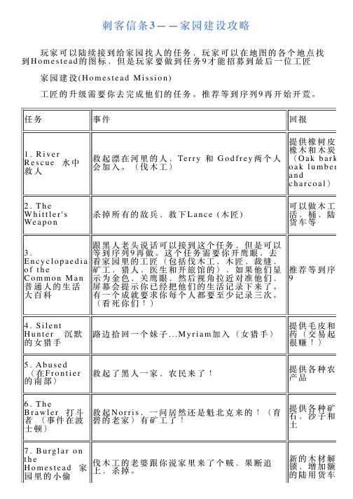
女猎手找你追捕一只惹事的大白猫,果断追 杀。
增加狐狸皮
11. Room at 英国兵毁了Oliver夫妇的旅馆,康纳劝说他们
the Inn 旅馆 留在他这里。重新开一家旅馆。Innkeeper加 制作食物和酒
房间
入
12. Cutting Ties 一刀两断 (事件在纽 约)
路上看到一个姑娘喊救人,原来她的妈妈被纠 缠住了,用拳头解决问题。裁缝加入。
救起Norris,一问居然还是魁北克来的!(育 碧的老家)有矿工了!
提供各种矿 石,沙子和粘 土
7. Burglar on
the Homestead 园里的小偷
家
伐木工的老婆跟你说家里来了个贼,果断追 上,杀掉。
新的木材解 锁,增加额外 的陆用货车
8. The Fight 两个伐木工又吵架了,这次还打起来,在这里 陆用货车的载
矿工再爱一次 的刀坏了。
等。
21. Bowl's Beginners 扔球
伐木工找你玩一个小游戏,先丢一个球在场地 里作为目标,然后尽量丢的离这个目标近一 些。我不知道有多少人玩赢了,反正我是输 了,不过不影响回报。
解锁新的木 材,做双肩袋 要用的!
22. Tools of the Trade 交易工具
3.
等到序列9再做。这个任务需要你开鹰眼,去
Encyclopaedia 看家园里的工匠(包括伐木工,木匠,裁缝,
of the
矿工,猎人,医生和开旅馆的),如果他们显
Common Man 示为金色,关鹰眼,然后视角拉近对准他们,
普通人的生活 屏幕会提示你已经把他们的生活记录下来了。
大百科
有一个成就要求你每个人都要至少记录三次。
文明3攻略3

3.靠海:有些城市建筑、奇迹或部队,如港口、沿海要塞、军舰等,只有在沿海城市才可以建造。
如果是选大陆或岛屿地图则这一位置更为重要。
4.城市周围大部分的地形为低洼平原,草地或平原;可以有1-2块丘陵或山地或1-2块森林或丛林。
最好不要有沙漠或冻土,除非你想试着在撒哈拉上建上海,在南极建纽约。
前2个条件为必须满足(如不满足请按CTRL-SHIFT-Q快速开始新游戏),后2个条件不一定要满足,只不过会增加游戏开始时的难度而已。
城市总督正确合理地利用城市总督为你管理城市会为你避免不少的麻烦。
方法是在城市上点击右键,选择“联系总督”就可以进入设置界面,决定让总督为你管理哪些事务。
老实说,这一点《文明3》的AI设计地的确不错。
你可以放心地让电脑来替你关注市民们的情绪,它决不让不高兴的市民数超过高兴的市民,除非发生战争或突然失去奢侈品资源,否则你根本不用担心会有暴动发生。
也可以让它管理城市的生产和发展,电脑会根据需要自动安排市民去最适合的地方工作,你所要做的只是派工人改造城市周边地形就可以了。
但是电脑的作用仅此而已,你还是要随时注意城市的建造,决定是制造什么样的军事或非军事单位、城市建筑或奇迹,毕竟掌握命运的人还是你自己嘛。
城市发展一开始你的任务只有一个就是:扩张、扩张、再扩张,直到把城市建到领国的边境。
毕竟只有在游戏初期领土扩张地代价是最小的。
你仅需派一个定居者在空地上“安营扎寨”就可以了。
你不妨想象一下美国历史上的“西进运动”:谁圈了一块地就等于拥有了这块土地。
所以,在确城市保安全的前提下尽可能多地造定居者,然后选择在资源丰富的地方建立新的城市,既扩张了自己地领土,抢占宝贵的资源,又可以压制电脑的发展。
试问,由古至今,哪一个强国不是疆域辽阔,物产丰富的?扩张领土的方式有两种。
电脑一般采用的是“滚雪球”的方式,即以首都为圆心每隔4-5格建一个城市。
这样做的好处就是使城市抱成一团,势力范围可以连成一整片。
但我却喜欢用“圈地”的方式,即以最快的速度直线向电脑所在方向扩张,直到与其接壤,然后沿着边境建一排城市,目的就是迫使电脑向相反的方向发展(如果它继续派定居者越过边境,你就可以警告威胁它)。
X3 地球人 攻略 资料 操作等大全 从入门级开始

《X3:地球人冲突》上手攻略(1)《X3:地球人冲突》上手攻略(1)Talk to Lt.Samuel Plinter流程:必须在足够近的距离才能够通话,所以先要靠近Lt. Plinter ,然后才能和他通话。
那艘Terran Scimitar 就是Lt. Plinter 的座舰。
对话时选“1、I'm reporting in for patrol duty.”(我来负行巡逻职责)接第一个主线任务。
相关操作:点左边的Personal -〉My Missions 弹出任务菜单,可以看到你接了些任务,进一步点这个任务,弹出菜单再点Show Briefing 可以看到任务详细内容。
按F1 切换第一人称视角炮位,和按F2 是第三人称视角看自己船只,想看其它角度,用小键盘上的数字键。
接下来是飞行。
先说手动飞行,X 是加速,Z 是减速,按鼠标左键不放就可以调整船头方向,鼠标右键是开火。
Q 和E 分别是逆时针和顺时针翻转(当你发现地图表现和实际情况相反时,最好回忆一下Q 和E 的作用)。
然后说下三种方法可以飞向目标:1、肉眼搜寻后,左键锁定,再按Shift + A(自动),或者手动飞过去。
2、用雷达搜寻,点屏幕左边的Navigation(导航)-> Sector Map (区域地图),然后可以看到地图右侧列出了本区域所有的空间站和舰船。
左键点他的座舰,会弹出一个菜单,点AutoPilot:Follow 则会直接自动飞向这个目标。
3、雷达找到目标后,点Select as target 先锁定这个目标,再按Shift + A 跟踪。
(具体用哪种要根据当时情况。
一般说来,目标是无敌意用第2种;目标有敌意但距离很远,用第三种;目标有敌意且距离很近,用第一种)在飞船的飞行过程中可以按“J”激活“Singularity Engine Time Accelerator”(奇点时间加速引擎)缩写SETA ,可以加快游戏中时间的流逝,节约现实中的时间。
《文明太空》DLC潮起打法分析套路心得
《⽂明太空》DLC潮起打法分析套路⼼得 《⽂明太空》是由F i r a x i s G a m e s研发的⼀款回合制策略类游戏,于2014年10⽉24⽇发⾏。
《⽂明太空》是《⽂明》系列的最新作,今天为⼤家分享⼀篇⽂明太空D L C潮起打法分析套路⼼得,希望有所收获。
P S:游戏版本以⽬前最新的1.1.0.1045为基准。
⾸先我想谈论的是游戏的乐趣,对于不同的玩家来说,这个游戏的乐趣所在是不⼀样的,很可能差异会很⼤,⽐如有的朋友喜欢追求征服的快感,不停追求极限的胜利回合数,⽽我则更偏爱种⽥,看着⾃⼰的殖民地不断成长壮⼤,最后等到阿波罗A I做⼤以后和它们进⾏终极的撕逼,因为我更多时候享受限定统治胜利⽅式带给我的乐趣,⼀局游戏动辄300+回合,这和追求200回合内其它游戏乐趣的玩家⾃然有所不同。
尽管我是如此偏爱种⽥流,但我在这个贴⼦之中会尽可能谈论到所有的游戏进⾏⽅式,以求最⼤限度的与各个流派的玩家交流我的游戏体验。
赞助商分析 游戏开局的设定⽅式——赞助商分析 当建⽴⼀个新的⾃定义游戏时,⾸先选择的是赞助商,原版中就有8个派系,⽽这个D L C又新添了4个派系,⽬前⼀共是12个派系,到⽬前为⽌我还没有全部尝试过,但是在我已经进⾏过的⼗⼏局游戏之中,还是可以清晰感受到不同派系的特点和实⽤度的。
客观的说,⽬前的版本中这些派系⽐较之下存在着明显的强弱之分。
⽆论是从游戏数据还是游戏体验来看, 泛亚合作组织、美洲开拓公司、波利尼利亚这三个派系⽆疑是顶级派系,泛亚拥有每个城市可以⼀回合秒建⼀个世界奇观的逆天特性,美洲有近乎B T的间谍⾏动⽀持,⽽波利拥有数量更多的贸易路线栏位。
其次,是其它若⼲派系各有千秋。
最后,法兰克伊⽐利亚、巴西利亚、宗肃堪称是垫底的三个派系,和其它派系特点⽐起来,它们的派系特性完全就是个鸡肋。
P S:这⾥需要格外注意⼀点,⼤家在开局选择派系的时候所看到的派系特性是可以在游戏中通过外交资本进⾏升级的!所有派系开局时派系特性是等级1,最⾼可以升级到等级3,有的派系(⽐如逆天的泛亚)的派系特性升级奖励⾮常鸡肋,⽽有的派系(⽐如同样逆天的美洲开拓)特性升级奖励则效果出⾊。
文明3升级到1
文明3升级到1.29简体中文版完全傻瓜指南---------文明3升级到1.29简体中文版完全傻瓜指南-------------文明3的最新版本为1.29(也常称为1.29f),这一版本是经历1.07、1.16、1.17和1.21后官方推出的最终版本,这一版本是各个版本中BUG最少、最稳定和游戏性最佳的版本。
经常在论坛看到玩家询问如何将自己的文明3升级到1.29或者升级不成功之类的问题,我在这里将将文明3各种版本的升级方法归纳整理出来,希望能为大家解除升级的困难。
无论你使用的是什么版本的文明3,都可以按照下列步骤升级:(1)安装文明3。
请在你的电脑上安装好能够运行的文明3,注意一定要阅读光盘中附带的文本文件,并安装光盘里附带的破解程序、补丁和注册表文件(光盘里不一定会有这些东西,没有的话没关系),安装完成后运行游戏,确认文明3可以正常运行,安装完的文明3文件大小大约有550M到600M左右。
假如安装完成后的程序无法运行,请更换你的文明3光盘后,直到安装的文明3(无论中文版还是英文版)能够正常运行。
(2)安装宽宽文明3版本转换器。
下载一下三个文件:civ3toenv100.part1.exe、civ3toenv100.part2.rar和civ3toenv100.part3.rar,地址如下:文件1:/civ/patch/civ3toenv100.part1.exe文件2:/civ/patch/civ3toenv100.part2.rar文件3:/civ/patch/civ3toenv100.part3.rar将这三个文件放置在任意的同一个目录下,双击运行civ3toenv100.part1.exe ,弹出“WinRAR自解压”窗口,点击“浏览”按钮选择你的文明3安装所在的目录后点击“安装”按钮,程序在执行完后会自动结束。
(3)将文明3升级到 1.29。
下载文明3英文 1.29升级补丁(下载地址:ftp:///patches/civ3/Civ3v129f.exe),下载完后运行Civ3v129f.exe,按提示安装它,中间会要求你选择的文明3安装的目录。
银河文明3图文全教程攻略游戏系统全解析

银河⽂明3-图⽂全教程攻略游戏系统全解析 ⼀、系统/界⾯教程 ⾸页菜单 新游戏:进⾏战役模式。
快速开启:进⾏快速对战模式。
战役模式:暂时未开放。
多⼈游戏:进⾏多⼈快速对战模式。
荣誉堂:查看世界排⾏榜。
读取游戏:读取已保存的游戏存档。
设置:进⾏游戏设置。
离开:离开《银河⽂明3》。
设置菜单 画⾯设置 分辨率:调整适合玩家显⽰器的分辨率。
全屏:开启窗⼜或全屏播放模式。
U I⼤⼩:调整⽤户界⾯的⼤⼩。
光亮度:调整游戏光亮度,数值从1⾄100。
对⽐度:调整游戏对⽐度,数值从1⾄100。
颗粒效果:开启或关闭颗粒效果。
画质预设:设置画质预设的模式。
反锯齿:设置反锯齿的模式。
凝固U I:开启或关闭凝固界⾯。
绽放效果:开启或关闭绽放效果。
地图倾斜:开启或关闭地图倾斜效果。
声⾳设置 S F X:开启或关闭特效⾳。
⾳乐:开启或关闭⾳乐。
S F X⾳量:调整S F X⾳量,数值从0⾄100。
界⾯按键⾳量:调整界⾯按键⾳量,数值从0⾄100。
⾳乐⾳量:调整⾳乐⾳量,数值从0⾄100。
话筒配置:设置话筒配置的类型。
界⾯设置 跳过介绍:开启或关闭跳过介绍。
绘制⽹格:开启或关闭绘制⽹格。
隐藏⽹格外露:开启或关闭隐藏⽹格外露。
镜头恢复:开启或关闭镜头恢复。
放⼤光标:开启或关闭放⼤光标。
⾃动展⽰控制线:开启或关闭⾃动展⽰控制线。
⿏标滑轮速度:调整⿏标滑轮速度。
⿏标滑轮延迟:调整⿏标滑轮延迟。
镜头移动速度:调整镜头移动速度。
⼯具提⽰:开启或关闭⼯具提⽰。
使⽤地区化数据:开启或关闭使⽤地区化数据。
截图格式:选择截图的图⽚格式。
反馈游戏数据:开启或关闭反馈游戏数据。
允许战⽃观测器:开启或关闭允许战⽃观测器。
影响⼯具提⽰:开启或关闭影响⼯具提⽰。
游戏设置 快速移动:开启或关闭快速移动。
允许m o d e:开启或关闭允许玩家⾃建模式。
⾃动保存:开启或关闭⾃动保存。
DNV-OS-C201

OFFSHORE STANDARDD ET N ORSKE VERITASDNV-OS-C201STRUCTURAL DESIGN OF OFFSHOREUNITS (WSD METHOD)APRIL 2005Since issued in print (April 2005), this booklet has been amended, latest in April 2006.See the reference to “Amendments and Corrections” on the next page.Comments may be sent by e-mail to rules@For subscription orders or information about subscription terms, please use distribution@Comprehensive information about DNV services, research and publications can be found at http :// , or can be obtained from DNV,Veritasveien 1, NO-1322 Høvik, Norway; Tel +47 67 57 99 00, Fax +47 67 57 99 11.© Det Norske Veritas. All rights reserved. No part of this publication may be reproduced or transmitted in any form or by any means, including photocopying and recording, without the prior written consent of Det Norske puter Typesetting (FM+SGML) by Det Norske Veritas.Printed in Norway.If any person suffers loss or damage which is proved to have been caused by any negligent act or omission of Det Norske Veritas, then Det Norske Veritas shall pay compensation to such person for his proved direct loss or damage. However, the compensation shall not exceed an amount equal to ten times the fee charged for the service in question, provided that the maximum compen-sation shall never exceed USD 2 million.In this provision "Det Norske Veritas" shall mean the Foundation Det Norske Veritas as well as all its subsidiaries, directors, officers, employees, agents and any other acting on behalf of Det Norske Veritas.FOREWORDDET NORSKE VERITAS (DNV) is an autonomous and independent foundation with the objectives of safeguarding life, prop-erty and the environment, at sea and onshore. DNV undertakes classification, certification, and other verification and consultancy services relating to quality of ships, offshore units and installations, and onshore industries worldwide, and carries out research in relation to these functions.DNV Offshore Codes consist of a three level hierarchy of documents:—Offshore Service Specifications. Provide principles and procedures of DNV classification, certification, verification and con-sultancy services.—Offshore Standards. Provide technical provisions and acceptance criteria for general use by the offshore industry as well asthe technical basis for DNV offshore services.—Recommended Practices. Provide proven technology and sound engineering practice as well as guidance for the higher levelOffshore Service Specifications and Offshore Standards.DNV Offshore Codes are offered within the following areas:A)Qualification, Quality and Safety Methodology B)Materials Technology C)Structures D)SystemsE)Special Facilities F)Pipelines and Risers G)Asset Operation H)Marine Operations J)Wind TurbinesAmendments and CorrectionsThis document is valid until superseded by a new revision. Minor amendments and corrections will be published in a separate document normally updated twice per year (April and October).For a complete listing of the changes, see the “Amendments and Corrections” document located at: /technologyservices/, “Offshore Rules & Standards”, “Viewing Area”.The electronic web-versions of the DNV Offshore Codes will be regularly updated to include these amendments and corrections.Amended April 2006,Offshore Standard DNV-OS-C201, April 2005 see note on front cover Changes – Page 3Changes April 2005—Sec.1. Unification of requirements, level of references, terms, definitions, lay-out, text, etc. with the LRFD stand-ards, i.e. general standard (DNV-OS-C101), the standards for various objects (DNV-OS-C102 to DNV-OS-C106), as well as the fabrication standard (DNV-OS-C401). —Sec.1 & Sec.2. Definition and application of design tem-perature and service temperature has been updated, and the terminology co-ordinated with the LRFD standards.—Sec.4. Overall conditions for fracture mechanics (FM) testing, and post weld heat treatment (PWHT) transferred here (from DNV-OS-C401). Requirements to FM adjusted to reflect results of more recent research work. —Sec.5. References to the more recent Recommended Prac-tices introduced e.g. DNV-RP-C201 (for Plates), updating references to CN 30.1.—Sec.3 D300. Specified tank pressures are harmonised with similar formulas in the LRFD standards, while simultane-ously attempted simplified and clarified.—Sec.11 to Sec.14. (Ref. to the various objects.) Formulas for sea pressure during transit are reorganised and clari-fied, improving readability.—Sec.12. Text covering redundancy and detailed design re-vised in line with DNV-OS-C104 (and the previous MOU-rules).—Sec.13. Text regarding the topics of tendon fracture me-chanics, composite tendons, and stability, as well as the CMC requirements are all updated, bringing the text in line with most recent revision of DNV-OS-C105.—Sec.14. Text updated in line with ongoing revision of DNV-OS-C106.D ET N ORSKE V ERITASOffshore Standard DNV-OS-C201, April 2005Amended April 2006, Page 4 – Changes see note on front coverD ET N ORSKE V ERITASAmended April 2006,Offshore Standard DNV-OS-C201, April 2005 see note on front cover Contents – Page 5CONTENTSSec. 1Introduction (9)A.General (9)A100Introduction (9)A200Objectives (9)A300Scope and application (9)A400Other than DNV codes (9)A500Classification (9)B.References (9)B100General (9)C.Definitions (10)C100Verbal forms (10)C200Terms (10)D.Abbreviations and Symbols (12)D100Abbreviations (12)D200Symbols (12)Sec. 2Design Principles (15)A.Introduction (15)A100General (15)A200Aim of the design (15)B.General Design Considerations (15)B100General (15)B200Overall design (15)B300Details design (15)C.Design Conditions (15)C100Basic conditions (15)D.Loading Conditions (16)D100General (16)D200Load (16)E.Design by the WSD Method (16)E100Permissible stress and usage factors (16)E200Basic usage factors (16)F.Design Assisted by Testing (16)F100General (16)F200Full-scale testing and observation of performance of existing structures (16)Sec. 3Loads and Load Effects (17)A.Introduction (17)A100General (17)B.Basis for Selection of Loads (17)B100General (17)C.Permanent Functional Loads (17)C100General (17)D.Variable Functional Loads (18)D100General (18)D200Variable functional loads on deck areas (18)D300Tank pressures (18)D400Lifeboat platforms (19)E.Environmental Loads (19)E100General (19)E200Environmental conditions for mobile units (19)E300Environmental conditionss for site specific units (19)E400Determination of hydrodynamic loads (19)E500Wave loads (19)E600Wave induced inertia forces (20)E700Current (20)E800Wind loads (20)E900Vortex induced oscillations (20)E1000Water level and tidal effects (20)E1100Marine growth (20)E1200Snow and ice accumulation............................................20E1300Direct ice load.. (20)E1400Earthquake (20)bination of Environmental Loads (21)F100General (21)G.Accidental Loads (21)G100General (21)H.Deformation Loads (21)H100General (21)H200Temperature loads (21)H300Settlements and subsidence of sea bed (21)I.Fatigue loads (22)I100General (22)J.Load Effect Analysis (22)J100General (22)J200Global motion analysis (22)J300Load effects in structures and soil or foundation (22)Sec. 4Structural Categorisation, Material Selection and Inspection Principles (23)A.General (23)A100 (23)B.Temperatures for Selection of Material (23)B100General (23)B200Floating units (23)B300Bottom fixed units (23)C.Structural Category (23)C100General (23)C200Selection of structural category (23)C300Inspection of welds (24)D.Structural Steel (24)D100General (24)D200Material designations (24)D300Selection of structural steel (25)D400Fracture mechanics (FM) testing (25)D500Post weld heat treatment (PWHT) (25)Sec. 5Structural Strength (26)A.General (26)A100General (26)A200Structural analysis (26)A300Ductility (26)A400Yield check (26)A500Buckling check (27)B.Flat Plated Structures and Stiffened Panels (27)B100Yield check (27)B200Buckling check (27)B300Capacity checks according to other codes (27)C.Shell Structures (27)C100General (27)D.Tubular Members, Tubular Joints and Conical Transitions.27 D100General (27)E.Non-Tubular Beams, Columns and Frames (28)E100General (28)Sec. 6Section Scantlings (29)A.General (29)A100Scope (29)B.Strength of Plating and Stiffeners (29)B100Scope (29)B200Minimum thickness (29)B300Bending of plating (29)D ET N ORSKE V ERITASOffshore Standard DNV-OS-C201, April 2005Amended April 2006, Page 6 – Contents see note on front coverB400Stiffeners (29)C.Bending and Shear in Girders (30)C100General (30)C200Minimum thickness (30)C300Bending and shear (30)C400Effective flange (30)C500Effective web (30)C600Strength requirements for simple girders (30)C700Complex girder systems (31)Sec. 7Fatigue (32)A.General (32)A100General (32)A200Design fatigue factors (32)A300Methods for fatigue analysis (32)A400Simplified fatigue analysis (33)A500Stochastic fatigue analysis (33)Sec. 8Accidental Conditions (34)A.General (34)A100General (34)B.Design Criteria (34)B100General (34)B200Collision (34)B300Dropped objects (34)B400Fires (34)B500Explosions (34)B600Unintended flooding (34)Sec. 9Weld Connections (36)A.General (36)A100Scope (36)B.Types of Welded Steel Joints (36)B100Butt joints (36)B200Tee or cross joints (36)B300Slot welds (37)B400Lap joint (37)C.Weld Size (37)C100General (37)C200Fillet welds (37)C300Partly penetration welds and fillet welds in crossconnections subject to high stresses (38)C400Connections of stiffeners to girders and bulkheads, etc..38 C500End connections of girders (39)C600Direct calculation of weld connections (39)Sec. 10Corrosion Control (40)A.General (40)A100Scope (40)B.Techniques for Corrosion Control Related to EnvironmentalZones (40)B100Atmospheric zone (40)B200Splash zone (40)B300Submerged zone (40)B400Internal zone (40)C.Cathodic Protection (41)C100General (41)C200Galvanic anode systems (41)C300Impressed current systems (42)D.Coating Systems (42)D100Specification of coating (42)Sec. 11Special Considerations for Column Stabilised Units (43)A.General (43)A100Assumptions and application (43)B.Structural Categorisation, Material Selection and InspectionPrinciples (43)B100General (43)B200Structural categorisation (43)B300Material selection (43)B400Inspection categories (44)C.Design and Loading Conditions (46)C100General (46)C200Permanent loads (46)C300Variable functional loads (46)C400Tank loads (46)C500Environmental loads, general (46)C600Sea pressures (47)C700Wind loads (47)C800Heavy components (47)C900Combination of loads (47)D.Structural Strength (47)D100General (47)D200Global capacity (47)D300Transit condition (47)D400Method of analysis (48)D500Air gap (48)E.Fatigue (48)E100General (48)E200Fatigue analysis (49)F.Accidental Conditions (49)F100General (49)F200Collision (49)F300Dropped objects (49)F400Fire (49)F500Explosion (49)F600Heeled condition (49)G.Redundancy (49)G100General (49)G200Brace arrangements (49)H.Structure in Way of a Fixed Mooring System (49)H100Structural strength (49)I.Structural Details (50)I100General (50)Sec. 12Special Considerations forSelf-Elevating Units (51)A.Introduction (51)A100Scope and application (51)B.Structural Categorisation, Material Selection and InspectionPrinciples (51)B100General (51)B200Structural categorisation (51)B300Material selection (51)B400Inspection categories (51)C.Design and Loading Conditions (51)C100General (51)C200Transit (52)C300Installation and retrieval (52)C400Operation and survival (52)D.Environmental Conditions (53)D100General (53)D200Wind (53)D300Waves (53)D400Current (53)D500Snow and ice (53)E.Method of Analysis (53)E100General (53)E200Global structural models (54)E300Local structural models (54)E400Fatigue analysis (55)F.Design Loads (55)F100General (55)F200Permanent loads (55)D ET N ORSKE V ERITASAmended April 2006,Offshore Standard DNV-OS-C201, April 2005 see note on front cover Contents – Page 7F300Variable functional loads (55)F400Tank loads (55)F500Environmental loads, general (55)F600Wind loads (55)F700Waves (56)F800Current (56)F900Wave and current (56)F1000Sea pressures during transit (57)F1100Heavy components during transit (57)F1200Combination of loads (57)G.Structural Strength (57)G100General (57)G200Global capacity (57)G300Footing strength (57)G400Leg strength (58)G500Jackhouse support strength (58)G600Hull strength (58)H.Fatigue Strength (58)H100General (58)H200Fatigue analysis (58)I.Accidental Conditions (58)I100General (58)I200Collisions (58)I300Dropped objects (58)I400Fires (58)I500Explosions (58)I600Unintended flooding (58)J.Miscellaneous requirements (59)J100General (59)J200Pre-load capasity (59)J300Overturning stability (59)J400Air gap (59)Sec. 13Special Considerations forTension Leg Platforms (TLP) (61)A.General (61)A100Scope and application (61)A200Description of tendon system (61)B.Structural Categorisation, Material Selection and InspectionPrinciples (62)B100General (62)B200Structural categorisation (62)B300Material selection (63)B400Design temperatures (63)B500Inspection categories (63)C.Design Principles (63)C100General (63)C200Design conditions (64)C300Fabrication (64)C400Hull and Deck Mating (64)C500Sea transportation (64)C600Installation (64)C700Decommissioning (64)C800Design principles, tendons (64)D.Design Loads (65)D100General (65)D200Load categories (65)E.Global Performance (65)E100General (65)E200Frequency domain analysis (66)E300High frequency analyses (66)E400Wave frequency analyses (66)E500Low frequency analyses (66)E600Time domain analyses (66)E700Model testing (67)E800Load effects in the tendons (67)F.Structural Strength (67)F100General (67)F200Hull (68)F300Structural analysis (68)F400Structural design.............................................................68F500Deck.. (68)F600Extreme tendon tensions (69)F700Structural design of tendons (69)F800Foundations (69)G.Fatigue (69)G100General (69)G200Hull and deck (69)G300Tendons (69)G400Foundation (70)H.Accidental Condition (70)H100Hull (70)H200Hull and deck (71)H300Tendons (71)H400Foundations (71)Sec. 14Special Considerations for Deep DraughtFloaters (DDF) (72)A.General (72)A100Introduction (72)A200Scope and application (72)B.Non-Operational Phases (72)B100General (72)B200Fabrication (72)B300Mating (72)B400Sea transportation (72)B500Installation (72)B600Decommissioning (73)C.Structural Categorisation, Selection of Material andExtent of Inspection (73)C100General (73)C200Material selection (73)C300Design temperatures (73)C400Inspection categories (73)C500Guidance to minimum requirements (73)D.Design Loads (74)D100Permanent loads (74)D200Variable functional loads (74)D300Environmental loads (74)D400Determination of loads (74)D500Hydrodynamic loads (74)E.Deformation Loads (74)E100General (74)F.Accidental Loads (75)F100General (75)G.Fatigue Loads (75)G100General (75)bination of Loads (75)H100General (75)I.Load Effect Analysis in Operational Phase (75)I100General (75)I200Global bending effects (75)J.Load Effect Analysis in Non-Operational Phases (75)J100General (75)J200Transportation (76)J300Launching (76)J400Upending (76)J500Deck mating (76)J600Riser installations (76)K.Structural Strength (76)K100Operation phase for hull (76)K200Non-operational phases for hull (76)K300Operation phase for deck or topside (77)K400Non-operational phases for deck or topside (77)L.Fatigue (77)L100General (77)L200Operation phase for hull (77)L300Non-operational phases for hull (77)D ET N ORSKE V ERITASOffshore Standard DNV-OS-C201, April 2005Amended April 2006, Page 8 – Contents see note on front coverL400Splash zone (77)L500Operation phase for deck or topside (78)L600Non-operational phases for deck or topside (78)M.Accidental Condition (78)M100General (78)M200Fire (78)M300Explosion (78)M400Collision (78)M500Dropped objects (78)M600Unintended flooding (78)M700Abnormal wave events (78)App. A Cross Sectional Types (80)A.Cross Sectional Types (80)A100General (80)A200Cross section requirements for plastic analysis (80)A300Cross section requirements whenelastic global analysis is used (80)App. B Methods and Models for Design of Column-Stabilised Units (82)A.Methods and Models (82)A100General (82)A200World wide operation (82)A300Benign waters or restricted areas (82)App. C Permanently Installed Units (83)A.Introduction (83)A100Application (83)B.Inspection and Maintenance (83)B100Facilities for inspection on location................................83C.Fatigue. (83)C100Design fatigue factors (83)C200Splash zone for floating units (83)App. D Certification of Tendon System (84)A.General (84)A100Introduction (84)B.Equipment categorization (84)B100General (84)C.Fabrication Record (84)C100General (84)D.Documentation Deliverables for Certification ofEquipment (85)D100General (85)E.Tendon Systems and Components (85)E100General (85)E200Tendon pipe (85)E300Bottom tendon interface (BTI) (86)E400Flex bearings (86)E500Foundations (86)E600Top tendon interface (TTI) (86)E700Intermediate tendon connectors (ITC) (86)E800Tendon tension monitoring system (TTMS) (86)E900Tendon porch (87)E1000Tendon corrosion protection system (87)E1100Load management program (LMP) (87)F.Categorisation of Tendon Components (87)F100General (87)G.Tendon Fabrication (88)G100General (88)D ET N ORSKE V ERITASAmended April 2006,Offshore Standard DNV-OS-C201, April 2005 see note on front cover Sec.1 – Page 9SECTION 1INTRODUCTIONA. GeneralA 100Introduction101 This offshore standard provides principles, technical re-quirements and guidance for the structural design of offshore structures, based on the Working Stress Design (WSD) meth-od.102 This standard has been written for general world-wide application. Statutory regulations may include requirements in excess of the provisions by this standard depending on size, type, location and intended service of the offshore unit or in-stallation.103 The standard is organised with general sections contain-ing common requirements and sections containing specific re-quirement for different type of offshore units. In case of deviating requirements between general sections and the ob-ject specific sections, requirements of the object specific sec-tions shall apply.A 200Objectives201 The objectives of this standard are to:—provide an internationally acceptable level of safety by de-fining minimum requirements for structures and structural components (in combination with referred standards, rec-ommended practices, guidelines, etc.)—serve as a contractual reference document between suppli-ers and purchasers—serve as a guideline for designers, suppliers, purchasers and regulators—specify procedures and requirements for offshore struc-tures subject to DNV certification and classification.A 300Scope and application301 This standard is applicable to the following types of off-shore structures:—column-stabilised units—self-elevating units—tension leg platforms—deep draught floaters.302 For utilisation of other materials, the general design principles given in this standard may be used together with rel-evant standards, codes or specifications covering the require-ments to materials design and fabrication.303 The standard is applicable to structural design of com-plete units including substructures, topside structures and ves-sel hulls.304 This standard gives requirements for the following: —design principles—structural categorisation—material selection and inspection principles—loads and load effect analyses—design of steel structures and connections—special considerations for different types of units. Requirements for foundation design are given in DNV-OS-C101.A 400Other than DNV codes401 Other recognised codes or standards may be applied pro-vided it is shown that the codes and standards, and their appli-cation, meet or exceed the level of safety of the actual DNV standard.402 In case of conflict between requirements of this standard and a reference document other than DNV documents, the re-quirements of this standard shall prevail.403 Where reference is made to codes other than DNV doc-uments, the latest revision of the documents shall be applied, unless otherwise specified.404 When code checks are performed according to other than DNV codes, the usage factors as given in the respective code shall be used.A 500Classification501 Classification principles, procedures and applicable class notations related to classification services of offshore units are specified in the DNV Offshore Service Specifications given in Table A1.502 Documentation requirements for classification are given by DNV-RP-A202.B. ReferencesB 100General101 The DNV documents in Table B1 are referred to in the present standards and contain acceptable methods for fulfilling the requirements in this standard.102 The latest valid revision of the DNV reference docu-ments in Table B2 applies. See also current DNV List of Pub-lications.103 The documents listed in Table B2 are referred in the present standard. The documents include acceptable methods for fulfilling the requirements in the present standard and may be used as a source of supplementary information. Only the referenced parts of the documents apply for fulfilment of the present standard.Table A1 DNV Offshore Service SpecificationsReference TitleDNV-OSS-101Rules for Classification of Offshore Drilling andSupport UnitsDNV-OSS-102Rules for Classification of Floating Productionand Storage UnitsDNV-OSS-103Rules for Classification of LNG/LPG FloatingProduction and Storage Units or Installations DNV-OSS-121Classification Based on Performance CriteriaDetermined by Risk Assessment MethodologyRules for Planning and Execution of MarineOperationsTable B1 DNV Reference DocumentsReference TitleDNV-OS-A101Safety Principles andArrangementDNV-OS-B101Metallic MaterialsDNV-OS-C101Design of Offshore Steel Struc-tures, General (LRFD method) DNV-OS-C301Stability and Watertight Integrity DNV-OS-C401Fabrication and Testing ofOffshore StructuresD ET N ORSKE V ERITASOffshore Standard DNV-OS-C201, April 2005Amended April 2006, Page 10 – Sec.1see note on front coverC. DefinitionsC 100Verbal forms101 Shall: Indicates a mandatory requirement to be followed for fulfilment or compliance with the present standard. Devia-tions are not permitted unless formally and rigorously justified, and accepted by all relevant contracting parties.102 Should: Indicates a recommendation that a certain course of action is preferred or particularly suitable. Alterna-tive courses of action are allowable under the standard where agreed between contracting parties but shall be justified and documented.103 May: Indicates a permission, or an option, which is per-mitted as part of conformance with the standard.C 200Terms201 Accidental condition: When the unit is subjected to ac-cidental loads such as collision, dropped objects, fire explo-sion, etc.202 Accidental loads: Loads which may occur as a result of accident or exceptional events, e.g. collisions, explosions, dropped objects.203 Atmospheric zone: The external surfaces of the unit above the splash zone.204 Cathodic protection: A technique to prevent corrosion of a steel surface by making the surface to be the cathode of an electrochemical cell.205 Characteristic load: The reference value of a load to be used in the determination of load effects. The characteristic load is normally based upon a defined fractile in the upper end of the distribution function for load.206 Characteristic strength: The reference value of structur-al strength to be used in the determination of the design strength. The characteristic strength is normally based upon a 5% fractile in the lower end of the distribution function for re-sistance.207 Characteristic value: The representative value associat-ed with a prescribed probability of not being unfavourably ex-ceeded during the applicable reference period.208 Classic spar: Shell type hull structure.209 Classification Note: The Classification Notes cover proven technology and solutions which is found to represent good practice by DNV, and which represent one alternative for satisfying the requirements given in the DNV Rules or other codes and standards cited by DNV. The Classification Notes will in the same manner be applicable for fulfilling the require-ments in the DNV Offshore Standards.210 Coating: Metallic, inorganic or organic material applied to steel surfaces for prevention of corrosion.211 Column-stabilised unit: A floating unit that can be relo-cated. A column-stabilised unit normally consists of a deck structure with a number of widely spaced, large diameter, sup-porting columns that are attached to submerged pontoons. 212 Corrosion allowance: Extra wall thickness added during design to compensate for any anticipated reduction in thick-ness during the operation.213 Damaged condition: The unit condition after accidental damage.214 Deep draught floater (DDF): A floating unit categorised with a relative large draught. The large draught is mainly intro-duced to obtain reduced wave excitation in heave and suffi-ciently high eigenperiod in heave such that resonant responses in heave can be omitted or minimised.215 Design brief: An agreed document presenting owner's technical basis, requirements and references for the unit design and fabrication.216 Design temperature: The design temperature for a unit is the reference temperature for assessing areas where the unit can be transported, installed and operated. The design temper-ature is to be lower or equal to the lowest mean daily tempera-ture in air for the relevant areas. For seasonal restricted operations the lowest mean daily temperature in air for the sea-son may be applied.217 Driving voltage: The difference between closed circuit anode potential and the protection potential.218 Dry transit: A transit where the unit is transported on a heavy lift unit from one geographical location to another. 219 Dynamic upending: A process where seawater is filled or flooded into the bottom section of a horizontally floating DDF hull and creating a trim condition and subsequent water filling of hull or moonpool and dynamic upending to bring the hull in vertical position.220 Environmental loads: Loads directly and indirectly due to environmental phenomena. Environmental loads are not a necessary consequence of the structures existence, use and treatments. All external loads which are responses to environ-mental phenomena are to be regarded as environmental loads, e.g. support reactions, mooring forces, and inertia forces. 221 Expected loads and response history: Expected load and response history for a specified time period, taking into ac-count the number of load cycles and the resulting load levels and response for each cycle.222 Expected value: The most probable value of a load dur-ing a specified time period.223 Fail to safe: A failure shall not lead to new failure, which may lead to total loss of the structure.DNV-OS-D101Marine Machinery Systems andEquipmentDNV-OS-E301Position MooringDNV-OS-F201Dynamic RisersDNV-RP-C103Column Stabilised UnitsDNV-RP-C201Buckling Strength of PlatedStructuresDNV-RP-C202Buckling Strength of Shells DNV-RP-C203Fatigue Strength Analysis ofOffshore Steel Structures Classification Note 30.1Buckling Strength Analysis ofBars and Frames, and SphericalShellsClassification Note 30.4 FoundationsClassification Note 30.5 Environmental Conditions andEnvironmental Loads Classification Note 31.5Strength Analysis of MainStructures of Self-elevating Units Table B2 Other referencesReference TitleAISC-ASD Manual of Steel Construction ASDAPI RP 2A – WSD with supplement 1Planning, Designing and Constructing Fixed Offshore Platforms – Working Stress DesignAPI RP 2T Planning, Designing and Constructing TensionLeg PlatformsBS 7910Guide on methods for assessing the acceptability offlaws in fusion welded structuresNACE TPC Publication No. 3. The role of bacteria in corrosionof oil field equipmentSNAME 5-5A Site Specific Assessment of Mobile Jack-Up UnitsD ET N ORSKE V ERITAS。
文明3攻略

一游戏设置(新手必看)文明种族(关于中国文明的属性设置,个人认为是《文明3》设计小组的一大败笔。
中国的属性应该为科技型和勤劳型才算合理,希望Firaxis下次出补丁的时候可以修改这个明显的错误。
但是,话又说回来,军事型和勤劳型的设置并不影响中国成为适合各种玩法的“完美”文明之一,原因我会在下文说明。
下面简单介绍一下各种文明属性的特点,玩家可以此选择适合自己的文明进行游戏。
商业型:贪污程度较低,不过效果没有想象中那么明显;增加大城市的商业点数,这在游戏中后期才会表现出来。
扩张型:在游戏的初期是一个很有优势的文明类型,因为它一开始比其它的文明多一个单位——侦察兵(移动力为2),所以可以更快地探出地图;扩张型文明部队冲进野蛮人村庄可以抢到较多的金子;从小部落(地图上像蘑菇一样东西)获得科技的可能性比其它文明大而且不会出现野蛮人来围攻你。
而且有了侦察兵,你就不用浪费宝贵的物资去造战士,而转去造工人、定居者或城市建筑。
但是不要忘了,扩张型文明的优势只是在游戏的初期,随着文明的发展,骑兵出现之后,侦察兵就没什么价值了。
勤劳型:工人工作速度比其它文明工人快一倍(发展出“可替换部件”的技术之后,速度再翻一倍!);增加6个人口以上的城市的物资点数(城市生产速度加快)。
工人工作速度快一倍的好处是不言而喻的。
理论上,因为工人灌溉、建矿、修路所花的时间少一半,你的文明发展速度应该比其它文明快一倍。
注:被俘虏的勤劳型文明工人不享有这一特点。
军事型战斗单位升级速度较快(新兵-普通-精英),故而更容易产生领袖。
有了领袖就可以造更多的集团军或者用来加速奇迹的建造。
军营和沿海要塞的造价便宜50%。
可能因为《文明3》的设计者都是和平主义者,使得《文明3》中的战争易守难攻。
如果不是用数量或技术上占优势的部队攻城的话,你会死得要多难看就有多难看。
本人就试过用3个战士和2个弓箭手攻击只有1个长矛兵防守的城市,结果全军覆没。
有关《文明3》战斗系统的说明请参考-战争篇宗教型寺庙和教堂价便宜50%;改换政治制度时处于无政府状态的时间只有一个回合。
命令与征服3——精华徵文GDI剧本过关攻略
第三篇 关卡名称:汉普顿锚地 难度:困难 主任务: 1: 破坏Nod的行动中心 (Destroy the Nod Operations Centre) 2: 破坏危害我军战船的轰炸机 (Destroy the bombers harassing our Battleships) 3: 破坏Nod的生产设备 (Destroy the Nod production facilities) 副任务: 1: 只用突击队员完成任务 (Complete the mission using only the Commando) 新获得的资讯: 1: 突击队员 (Commando) 2: 运输箱: 机会主义的目标 (Logistics Crates: Targets of Opportunity) 3: 机器中的鬼神 (The Ghost in the Machine) 攻略: 这关比起Nod的相似那关要简单点嘛~~ 一开始有一个突击队员, 向北走会立刻见到对方一堆小兵, 尽情射杀就 好了~~ 清乾淨之后可以再稍稍向北走, 会见到P1的目标, 这时有两个做法: 一是直接用走的过去, 杀光附近的黑手, 然后炸掉目标;二是走到行动中心 南边的一堆货柜后面, 再用跳的跳过去行动中心后方直接炸掉目标, 利用行 动中心挡着对方, 在炸掉后才射杀那些找死的黑手。 完成后会有地图扩大的事件发生, 看完后可以继续往北走, 直到差不多 地图的最右上角, 会见到一堆小兵加一座电厂, 都清乾淨之后会见到附近有 一个升级箱子, 拿了之后要快点往P2目标~~ 如果不在意箱子的话也可以不 拿吧..? 向P2进发时如果遇到对方挡路的话, 小兵可以直接射, 又或者可以趁他 们经过那个红油桶附近时射爆油桶, 这样就可以清掉~ 如果遇到载具的话也 请用红油桶炸掉。中途该会见到升级及回血箱, 请拿一下~~ 很轻鬆的就可以炸掉那个航空塔了~~炸了之后可以再向P3出发~~直接 走过去就可以了, 会遇到一架电单车走过去挡路, 可以想法子炸掉, 也可以 不管, 直接走过去~~ 到了差不多见到那堆建筑时, 会见到一大堆部队在等 你, 这时可以不必起冲突~~ 稍微在那堆目标建筑往南有一个空地, 那边给 货柜隔开了, 突击队员不会惹起甚麽反应~ 选一个最接近目标的地方然后跳 进去吧~~ 这时大概挂星了吧?? 所以不必担心血量的~ 跳进去先挑最近的 来炸~~之后可以跟对方部队来一个捉迷藏~~ 一面以建筑物作盾, 减少给小 兵射, 一方面边走边炸那些用完的建筑物~~
NEMA 1000
NEMA MW 1000 M AGNET W IRENEMA Standards Publication MW 1000-2003Magnet WirePublished byNational Electrical Manufacturers Association1300 North 17th Street, Suite 1847Rosslyn, Virginia 22209© Copyright 2003 by the National Electrical Manufacturers Association. All rights including translation into other languages, reserved under the Universal Copyright Convention, the Berne Convention for the Protection of Literary and Artistic Works, and the International and Pan American Copyright Conventions.NOTICE AND DISCLAIMERThe information in this publication was considered technically sound by the consensus of persons engaged in the development and approval of the document at the time it was developed. Consensus does not necessarily mean that there is unanimous agreement among every person participating in the development of this document.The National Electrical Manufacturers Association (NEMA) standards and guideline publications, of which the document contained herein is one, are developed through a voluntary consensus standards development process. This process brings together volunteers and/or seeks out the views of persons who have an interest in the topic covered by this publication. While NEMA administers the process and establishes rules to promote fairness in the development of consensus, it does not write the document and it does not independently test, evaluate, or verify the accuracy or completeness of any information or the soundness of any judgments contained in its standards and guideline publications.NEMA disclaims liability for any personal injury, property, or other damages of any nature whatsoever, whether special, indirect, consequential, or compensatory, directly or indirectly resulting from the publication, use of, application, or reliance on this document. NEMA disclaims and makes no guaranty or warranty, expressed or implied, as to the accuracy or completeness of any information published herein, and disclaims and makes no warranty that the information in this document will fulfill any of your particular purposes or needs. NEMA does not undertake to guarantee the performance of any individual manufacturer or seller’s products or services by virtue of this standard or guide.In publishing and making this document available, NEMA is not undertaking to render professional or other services for or on behalf of any person or entity, nor is NEMA undertaking to perform any duty owed by any person or entity to someone else. Anyone using this document should rely on his or her own independent judgment or, as appropriate, seek the advice of a competent professional in determining the exercise of reasonable care in any given circumstances. Information and other standards on the topic covered by this publication may be available from other sources, which the user may wish to consult for additional views or information not covered by this publication.NEMA has no power, nor does it undertake to police or enforce compliance with the contents of this document. NEMA does not certify, test, or inspect products, designs, or installations for safety or health purposes. Any certification or other statement of compliance with any health or safety–related information in this document shall not be attributable to NEMA and is solely the responsibility of the certifier or maker of the statement.MW1000-2003Page iCONTENTSPage Foreword (xi)How to Use this Publication (xii)Part 1 GENERAL1.1 Scope (1)1.2 Normative References and Authorized Engineering Information (AEI) (1)1.3 Definitions (2)1.4 Materials (4)1.4.1 Conductors – Round, Square, and Rectangular, Copper and Aluminum (4)1.4.2 Insulating Materials (4)1.5 Manufacturing (5)of Insulation (5)1.5.1 Application1.5.2 Intermediate Sizes (5)1.5.3 Joints (5)1.5.4 Packaging (6)Conditions and Parameters (6)1.6 Test1.6.1 Safety Statement (6)of Specimens (6)1.6.2 Selection1.6.3 AmbientConditions of Test (6)Frequency (6)1.6.4 Power1.6.5 Mandrels (7)and Square Wire (7)1.6.6 Rectangular1.6.7 Round Wire (7)Conformance (8)1.6.8 Periodic1.6.9 Retests (8)1.7 Unitsof Measure (8)Class of Magnet Wire (8)1.8 Thermal1.9 OrderingInformation (8)Identification Number (8)1.9.1 ProductOrdering Data (9)1.9.2 MinimumTables1-1 Dimensions for Bare and Film Insulated Round Magnet Wire (10)1-2 Round Copper Wire, Ultra Fine Sizes by Resistance (14)1-3 Dimensions for Round Film Insulated Self-Bonding Magnet Wire (15)1-4 Dimensions for Single Glass Fiber Covered Round Bare,Single Film Coated and Heavy Film Coated Wire (17)1-5 Dimensions for Double Glass Fiber Covered Round Bare,Single Film Coated and Heavy Film Coated Wire (19)1-6 Dimensions for Single Polyester Glass Fiber Covered Round Bare,Single Film Coated and Heavy Film Coated Wire (21)1-7 Dimensions for Double Polyester Glass Fiber Covered Round Bare,Single Film Coated and Heavy Film Coated Wire (23)1-8 Dimensions and Radii for Rectangular Bare Wire (25)Conductor Tolerances (25)Rectangular1-9 BareMW 1000-2003Page ii1-10 Film Insulated Rectangular Magnet WireIncrease in Thickness and Width Due to Film Coating (25)of Square Bare Wire (26)1-11 Dimensions1-12 Heavy and Quadruple Film Insulated Square Magnet WireIncrease in Dimensions Due to Film Coating (27)1-13 Range of Increase in Dimensions, InchesSingle Glass Fiber Covered Heavy Film Insulated Rectangular Copper Wire (28)1-14 Range of Increase in Dimensions, InchesDouble Glass Fiber Covered Bare Rectangular Copper Wire (29)1-15 Range of Increase in Dimensions, InchesDouble Glass Fiber Covered Heavy Film Coated Rectangular Copper Wire (30)1-16 Range of Increase in Dimensions, InchesSingle Polyester Glass Fiber Covered Heavy Film Insulated Rectangular Copper Wire (31)1-17 Range of Increase in Dimensions, InchesDouble Polyester Glass Fiber Covered Bare Rectangular Copper Wire (32)1-18 Range of Increase in Dimensions, InchesDouble Polyester Glass Fiber Covered Heavy Film Coated Rectangular Copper Wire (33)1-19 Single Glass Fiber Covered, Heavy Film Insulated Square Copper Magnet Wire– Minimum Increase and Maximum Overall Dimensions Due to Insulation (34)1-20 Single Polyester Glass Fiber Covered Heavy Film Insulated Square Copper Magnet Wire-Minimum Increase and Maximum Overall Dimensions Due to Insulation (35)1-21 Double Glass Fiber Covered, Bare or Heavy Film Insulated Square Copper Magnet Wire–Minimum Increase and Maximum Overall Dimensions Due to Insulation (36)1-22 Double Polyester Glass Fiber Covered, Bare or Heavy Film Insulated Square Copper Magnet Wire–Minimum Increase and Maximum Overall Dimensions Due to Insulation (37)1-23 Comparison Between AWG and IEC R-40 Series Bare Wire Diameters (38)1-24 Comparison Between NEMA and IEC Increases and Overall Diameters (40)MW1000-2003Page iiiCONTENTS (continued)Part 2 PROPERTIES AND REQUIREMENTSSpecification Number ThermalClassRound Rectangularand SquarePageNo.MW 2-C Polyurethane for solderable applications(Single and Heavy)105 X — 2MW 3-C Polyurethane with self-bonding overcoat forsolderable applications (Types 1 and 2)105 X — 3 MW 5-C Polyester (Single and Heavy) 155 X — 4MW 6-C Polyamide (Single and Heavy) 105 X — 5MW 9-C Epoxy (Single, Heavy, and Triple) 130 X — 6MW 14-C Epoxy (Heavy and Quadruple) 130 — X 7MW 15-A Polyvinyl Acetal (Single and Heavy) 105 X — 8MW 15-C Polyvinyl Acetal (Single, Heavy, and Triple) 105 X — 9MW 16-C Polyimide (Single Heavy, Triple, andQuadruple)240 X — 10–17MW 17-C Polyvinyl acetal overcoated with polyamide(Single and Heavy)105 X — 18 MW 18-A Polyvinyl acetal (Heavy and Quadruple) 105 — X 19MW 18-C Polyvinyl acetal (Heavy and Quadruple) 105 — X 20MW 19-C Polyvinyl acetal with self-bonding overcoat(Types 1, 2 and 3)105 X — 21 MW 20-C Polyimide (Heavy and Quadruple) 240 — X 22MW 24-A Polyester (amide) (imide) overcoated withpolyamide (Single and Heavy)155 X — 23MW 24-C Polyester (amide) (imide) overcoated withpolyamide (Single, Heavy and Triple)155 X — 24MW 26-C Polyester (imide) for solderable applications(Single and Heavy)155 X — 25MW 27-C Polyester (imide) overcoated with polyamidefor solderable applications (Single and Heavy)155 X — 26MW 28-A Polyurethane overcoated with polyamide forsolderable applications (Single and Heavy)130 X — 27MW 28-C Polyurethane overcoated with polyamide forsolderable applications (Single and Heavy)130 X — 28MW 29-C Polyurethane overcoated with polyamide andself-bonding overcoated for solderableapplications (Types 1 and 2)105 X — 29MW 30-C Polyester (amide) (imide) (Single, Heavy, andTriple)180 X — 30MW 31-C Paper covered 90 or105X — 31MW 32-C Double paper single cotton covered 90 or105— X 32–33MW 33-C Paper covered 90 or105— X 34MW 1000-2003Page ivPart 2 PROPERTIES AND REQUIREMENTSSpecification Number ThermalClassRound Rectangularand SquarePageNo.MW 35-A Polyester (amide)(imide) overcoated withpolyamideimide (Single and Heavy)220 X — 35MW 35-C Polyester (amide)(imide) overcoated withpolyamideimide (Single, Heavy and Triple)200 X — 36MW 36-A Polyester (amide)(imide) overcoated withpolyamideimide (Heavy and Quadruple)220 — X 37MW 36-C Polyester (amide)(imide) overcoated withpolyamideimide (Heavy and Quadruple)200 — X 38 MW 41-C Glass fiber covered (Single and Double) 155 X — 39MW 42-C Glass fiber covered (Single and Double) 155 — X 40MW 43-C Glass fiber covered silicone treated(Single and Double)200 — X 41MW 44-C Glass fiber covered silicone treated(Single and Double)200 X — 42MW 45-C Polyester glass fiber covered(Single and Double)155 X — 43MW 46-C Polyester glass fiber covered(Single and Double)155 — X 44MW 47-C Polyester glass fiber covered silicone treated(Single and Double)200 X — 45MW 48-C Polyester glass fiber covered silicone treated(Single and Double)200 — X 46 MW 50-C Glass fiber covered, High Temperatureorganic varnish treated (Single and Double)180 X — 47MW 51-C Polyester glass fiber covered, HighTemperature organic varnish treated (Singleand Double)180 X — 48MW 52-C Glass fiber covered, High Temperatureorganic varnish treated (Single or Double)180 — X 49MW 53-C Polyester glass fiber covered, HighTemperature organic varnish treated (Singleand Double)180 — X 50MW 60-A Aromatic polyamide paper covered (Paper) 220 — X 52–53MW 60-C Aromatic polyamide paper covered (Paper) 220 — X 54–55MW 61-A Aromatic polyamide paper covered (Paper) 220 X — 56–57MW 61-C Aromatic polyamide paper covered (Paper) 220 X — 58–59MW 62-C Aromatic Polyimide tape covered 220 — X 60MW 63-C Aromatic Polyimide tape covered 220 X — 61MW 72-C Polyester (amide)(imide) for HermeticApplications (Heavy)180 X — 62MW 73-A Polyester (amide)(imide) overcoated withpolyamideimide for Hermetic Applications220 X — 63MW 73-C Polyester (amide)(imide) overcoated withpolyamideimide for Hermetic Applications200 X — 64 MW 74-A Polyester (amide)(imide) (Single and Heavy) 220 X — 65(continued)MW1000-2003Page v Part 2 PROPERTIES AND REQUIREMENTSSpecification Number ThermalClassRound Rectangularand SquarePageNo.MW 74-C Polyester (amide)(imide) (Single and Heavy) 200 X — 66MW 75-C Polyurethane for solderable applications(Single and Heavy)130 X — 67MW 76-A Polyester (amide)(imide) overcoated withpolyamide (Single and Heavy)180 X — 68MW 76-C Polyester (amide)(imide) overcoated withpolyamide (Single, Heavy and Triple)180 X — 69MW 77-C Polyester (imide) for solderable applications(Single and Heavy)180 X — 70MW 78-C Polyester (imide) overcoated with polyamidefor solderable applications (Single and Heavy)180 X — 71MW 79-C Polyurethane for solderable applications(Single, Heavy and Triple)155 X — 72MW 80-A Polyurethane overcoated with polyamide forsolderable applications (Single and Heavy)155 X — 73MW 80-C Polyurethane overcoated with polyamide forsolderable applications (Single, Heavy, Triple)155 X — 74 MW 81-C Polyamideimide (Single and Heavy) 220 X — 75MW 82-C Polyurethane for solderable applications(Single, Heavy and Triple)180 X — 76MW 83-C Polyurethane overcoated with polyamide forsolderable applications (Single, Heavy,Triple)180 X — 77MW 102-A Polyester (Amide) (Imide) overcoated withpolyamideimide and self-bonding overcoat(Type 1 and Type 2)180 X — 78MW 102-C Polyester (Amide) (Imide) overcoated withpolyamideimide and self-bonding overcoat(Type 1 and Type 2)180 X — 79TablesS (MW 16-C) Polyimide Single Film Insulated Round Copper Magnet Wire, Thermal Class 240 (11)H (MW 16-C) Polyimide Heavy Film Insulated Round Copper Magnet Wire, Thermal Class 240 (13)T (MW 16-C) Polyimide Triple Film Insulated Round Copper Magnet Wire, Thermal Class 240 (15)Q (MW 16-C) Polyimide Quadruple Film Insulated Round Copper Magnet Wire, Thermal Class 240..17PC (MW 32-C) Range of Increase in Dimensions (Inches) Due to Double Paper Single Cotton Covering (33)PR (MW 60-A) Increase in Dimensions of Rectangular Wire Due to Paper Covering (53)PSQ (MW 60-A) Dimensions 1–4/0 AWG (53)PR (MW 60-C) Increase in Dimensions of Rectangular Wire Due to Paper Covering (55)PSQ (MW 60-C) Dimensions 1–4/0 AWG (55)PR (MW 61-A) Dimensions 4/0–9 AWG (57)PR (MW 61-C) Dimensions 4/0–9 AWG (59)TR (MW 63-C) Insulated Wire Dimensions (61)(continued)MW 1000-2003Page viCONTENTS (continued)Part 2PROPERTIES AND REQUIREMENTS LISTING BY THERMAL CLASS, INSULATION, COATING AND FORMThermal Class Insulation, Covering and Form See Part 2, SectionAluminumCopperPageNo. FILM INSULATED ROUND MAGNET WIRE105 Polyamide -MW6-C 5105 Polyvinyl acetal MW 15-A MW 15-C 8, 9105 Polyvinyl acetal overcoated with polyamide - MW 17-C 18105 Solderable Polyurethane - MW 2-C 2105 Solderable Polyurethane and self-bonding overcoat - MW 3-C 3105 Solderable Polyurethane overcoated with polyamide and self-bonding overcoat -MW29-C 29105 Polyvinyl acetal and self-bonding overcoat - MW 19-C 21 130 Epoxy -MW9-C 6 130 Solderable Polyurethane overcoated with polyamide MW 28-A MW 28-C 27, 28 130 Solderable Polyurethane - MW 75-C 67 155 Polyester -MW5-C 4 155 Polyester (amide)(imide) overcoated with polyamide MW 24-A MW 24-C 23, 24 155 Solderable Polyester (imide) - MW 26-C 25 155 Solderable Polyester (imide) overcoated with polyamide - MW 27-C 26 155 Solderable Polyurethane - MW 79-C 72 155 Solderable Polyurethane overcoated with polyamide MW 80-A MW 80-C 73, 74 180 Polyester(amide)(imide) -MW30-C30 180 Polyester (amide)(imide) overcoated with polyamide MW 76-A MW 76-C 68, 69 180 Polyester (amide)(imide) overcoated withpolyamideimide and self-bonding overcoatMW 102-A MW 102-C 78, 79 180 Solderable Polyester (imide) - MW 77-C 70 180 Solderable Polyester (imide) overcoated with polyamide - MW 78-C 71 180 Hermetic Polyester (amide)(imide) - MW 72-C 62 180 Solderable Polyurethane - MW 82-C 76 180 Solderable Polyurethane overcoated with Polyamide - MW 83-C 77200 Polyester (amide)(imide) overcoated withpolyamideimide -MW35-C 36200 Polyester(amide)(imide) -MW74-C66200 Hermetic Polyester (amide)(imide) overcoated withpolyamideimide -MW73-C 64220 Polyester (amide)(imide) overcoated withpolyamideimideMW 35-A - 37 220 Polyester(amide)(imide) MW74-A- 65 220 Hermetic Polyester (amide)(imide) overcoated withpolyamideimideMW 73-A - 64 220 Polyamideimide MW81-C75 240 Hermetic Polyimide - MW 16-C 10–17FILM INSULATED RECTANGULAR AND SQUARE WIREMW1000-2003Page viiPart 2PROPERTIES AND REQUIREMENTS LISTING BY THERMAL CLASS, INSULATION, COATING AND FORMThermal Class Insulation, Covering and Form See Part 2, SectionAluminumCopperPageNo. 105 Polyvinyl acetal MW 18-A MW 18-C 19, 20130 Epoxy -MW14-C7200 Polyester (amide)(imide) overcoated withpolyamideimide -MW36-C 38220 Polyester (amide)(imide) overcoated withpolyamideimideMW 36-A - 37 240 Polyimide -MW20-C22 FIBROUS COVERED ROUND MAGNET WIRE90 or 105 Paper covered - MW 31-C 31 155 Glass fiber covered - MW 41-C 39 155 Polyester glass fiber covered - MW 45-C 43180 Glass fiber covered, High temperature organicvarnish treated -MW50-C 47180 Polyester glass fiber covered, High temperatureorganic varnish treated -MW51-C 48200 Glass fiber covered, silicone treated - MW 44-C 42 200 Polyester glass fiber covered, Silicone treated - MW 47-C 45 220 Aromatic polyamide paper covered MW 61-A MW 61-C 56–59 220 Aromatic polyimide tape covered - MW 63-C 61FIBROUS COVERED RECTANGULAR & SQUARE MAGNET WIRE90 or 105 Double paper, Single cotton covered - MW 32-C 32–33 90 or 105 Paper covered - MW 33-C 34 155 Glass fiber covered - MW 42-C 40 155 Polyester glass fiber covered - MW 46-C 44180 Glass fiber covered, High temperature organicvarnish treated -MW52-C 49180 Polyester glass fiber covered, High temperatureorganic varnish treated -MW53-C 50200 Glass fiber covered, Silicone treated - MW 43-C 41 200 Polyester glass fiber covered, Silicone treated - MW 48-C 46 220 Aromatic polyamide paper covered MW 60-A MW 60-C 52–55 220 Aromatic polyimide tape covered - MW 62-C 60MW 1000-2003Page viiiCONTENTS (continued)Part 3 TEST PROCEDURES3.1 Safety Statement (1)ROUTINE TESTS3.2 Dimensions (1)3.2.1 Round Wire (1)and Square Wire (3)3.2.2 Rectangularand Flexibility (3)3.3 Adherence3.3.1 Elongation and Mandrel Wrap Method (3)Wrap Method (4)3.3.2 Mandrel3.3.3 Elongation Method (4)Cut and Elongation Method (4)3.3.4 Circumferential3.3.5 Bend and Shot Dielectric Method (4)3.3.6 Flat and Edge Bend Method (4)3.4 Elongation (4)3.5 Heat Shock (6)3.6 Reserved (6)3.7 Springback (Specified for Copper Conductors Only) (6)3.7.1 MandrelWrap Method (6)3.7.2 Deflection Method (All Rectangular and Round Sizes Larger than 14 AWG) (10)3.8 Dielectric Breakdown (11)Procedure—General (11)3.8.1 TestElectrode Method (11)3.8.2 FoilPair Method (12)3.8.3 TwistedPair Method (14)3.8.4 Wound3.8.5 Layer Method (14)Method (14)3.8.6 Bend3.8.7 Cylinder Method (15)3.9 Continuity (17)3.9.1 General (17)3.9.2 High-Voltage Direct Current Continuity (14-44 AWG) (17)3.9.3 Low-Voltage Direct Current Continuity (45-56 AWG) (18)3.10 Completeness of Cure (19)3.10.1 Toluene-Ethanol Boil Method (19)3.10.2 Dissipation Factor Method (20)3.11 Reserved (22)3.12 Coverage (22)3.12.1 Mandrel Wrap Method (22)3.12.2 Flat Bend Method (22)3.13 Solderability (22)3.13.1 General (22)3.13.2 Self-Supported Specimen Method (14-36 AWG) (22)3.13.3 Fixture-Supported Specimen Method (37-56 AWG) (22)MW 1000-2003Page ixPERIODIC CONFORMANCE TESTS3.50 Thermoplastic Flow (24)3.50.1 Apparatus (24)3.50.2 Procedure (24)3.51 Solubility (25)3.51.1 Round Film Insulated Wire (10 AWG and Finer)........................................................25 3.51.2 Round Wire Larger than 10 AWG, Rectangular and Square Wire ............................25 3.52Dielectric Strength at Rated Temperature...............................................................................26 3.52.1 Test Procedure...........................................................................................................26 3.53Reserved.................................................................................................................................26 3.54Transformer Oil Resistance and Hydrolytic Stability...............................................................26 3.54.1 Principal of Test..........................................................................................................26 3.54.2 Test Apparatus...........................................................................................................26 3.54.3 Short Term Exposure Test.........................................................................................26 3.54.4 Long Term Exposure Test..........................................................................................27 3.55Refrigerant (R-22) Extraction ..................................................................................................27 3.55.1 Preparation of Specimens..........................................................................................28 3.55.2 Environmental Conditioning .......................................................................................28 3.55.3 Collecting Residue......................................................................................................29 3.55.4 Determination of Results............................................................................................30 3.56Retained Dielectric after R-22 Conditioning............................................................................30 3.57Bond ........................................................................................................................................31 3.57.1 Preparation of Specimens (31)3.57.2 Heating and Solvent Bonding.....................................................................................31 3.57.3 Room Temperature Bonding......................................................................................32 3.57.4 Elevated Temperature Bond Test Procedure.............................................................32 3.58Thermal Endurance.................................................................................................................33 3.58.1 Test Procedure...........................................................................................................33 3.59Scrape Resistance..................................................................................................................33 3.59.1 Apparatus...................................................................................................................33 3.59.2 Test Procedure...........................................................................................................34 Tables3.2.1Specification for Micrometer Anvil Diameter and Spindle Force...............................................2 3.3.1Adherence and Flexibility: Elongation and Mandrel Diameters ................................................3 3.4.1Minimum Percent Elongation, Square and Rectangular Wire...................................................4 3.4.2 MinimumPercent Elongation, Round Wire...............................................................................5 3.5.1Heat Shock: Elongation and Mandrel Diameters......................................................................6 3.7.1Springback - Mandrel Wrap Method..........................................................................................9 3.8.2Minimum Dielectric Breakdown Voltage—Foil Method...........................................................12 3.8.3.1Twisted Pair Method: Tensions and Rotations........................................................................12 3.8.3.2Minimum Dielectric Breakdown Voltage—Twisted Pair Method.............................................13 3.8.6 BendMethod Mandrel Sizes...................................................................................................14 3.8.7.1Rate of Increase in Voltage—Cylinder Method.......................................................................15 3.8.7.2 Cylinder Method Test Loads (16)MW 1000-2003Page x3.8.7.3 Minimum Dielectric Breakdown Voltage—Cylinder Method (16)3.9.2.1 Test Voltage (DC Volts ±5%) and Maximum Fault Count per 100 Feet (17)3.9.2.2 Threshold Fault Current (18)Continuity—Maximum Fault Count per 100 Feet (19)3.9.3 Low-Voltage3.50.2 Thermoplastic Flow Test Loads (24)Vessel Components (27)3.54.4 PressureSiphonCup Dimensions (28)3.55.1 TypicalTest Parameters (31)3.57.1 Bond3.59.1 Standard Scrape Resistance of Round Film Insulated Magnet Wire (35)3.59.2 Reduced Scrape Resistance of Round Film Insulated Magnet Wire (35)Figuresthe Springback Scale (7)3.7.1.1 Detailsof3.7.1.2 Springback Tester After Winding a Coil Under Tension (8)3.7.1.3 Photograph of Possible Appearance of the Springback Scales (8)3.7.2 Apparatus for Springback Deflection Method (10)PairSpecimen Winder (14)3.8.4 WoundApparatusfor Cylinder Method (15)3.8.7 Test3.9.3 Bath of Mercury or Other Suitable Material (19)3.10.2 Electrode and Specimen Arrangement for Dissipation Factor Test (21)Test Specimen Fixture (23)3.13.3 Solderability3.51.1 MachineSolubility Scrape (25)forExtractable Siphon Cup (28)3.55.1 Refrigerant3.55.2 Condenser Coil (29)3.55.3 Condenser Coil Siphon Cup Assembly (29)CoilPrep Fixture (31)3.57.1 BondStrength Test Fixture (32)3.57.3.1 BondTest Fixture (32)3.57.3.2 Bond3.59.1 MachineScrape Resistance (34)forAppendicesA Reference Test Conditions and Procedures for Film-Insulated Magnet Wire....................................A–1B Magnet Wire Packaging and Labeling................................................................................................B–11000-2003MWPage xiForewordThis publication supersedes NEMA Standards Publication MW 1000-1997. It is currently under review by ANSI for approval as an American National Standard.The standards contained in this publication are periodically reviewed by the NEMA Magnet Wire Section for revisions considered to be necessary to keep them up to date with changes in technology. Proposedor recommended revisions should be submitted to:Vice President, EngineeringNational Electrical Manufacturers Association1300 North 17th Street, Suite 1847Rosslyn, Virginia 22209These standards were developed by the Magnet Wire Section of NEMA, working closely with representatives of various industries that use magnet wire. At the time they were approved, the Magnet Wire Section had the following members:Bridgeport Insulated Wire Company—Bridgeport, CTElektrisola, Inc.—Boscawen, NHMagnekon—San Nicolas, NL, MexicoNexans—Markham, ON, CanadaPhelps Dodge Magnet Wire Company—Fort Wayne, INRea Magnet Wire Company, Inc.—Fort Wayne, INRea Algonquin Osceola Manufacturing Plant (formerly Southwire Company)—Osceola, AREssex Group, Inc.—Fort Wayne, INUniversal Lighting Technologies—Gallman, MSMW 1000-2003Page xiiHow to Use This PublicationPart 1 (blue, if in print) of this publication deals with information common to all types of magnet wire, that is, ordering information, general material requirements, general test conditions, definitions and manufacturing data in support of thermal rating. This part also includes dimensions with metric equivalents for all bare, minimum insulation increase, and overall dimensions for all Part 2 MW specification requirements. The exception to this is MW 16, where the dimensional and other requirements are provided in Part 2.Part 2 (yellow, if in print) consists of product specifications requirements (other than dimensions) for magnet wire with different types of coatings and/or coverings. Insofar as possible, the product specifications are complete on one sheet since they are arranged to include only one insulation or covering per sheet. The title on each individual sheet identifies the product. (Example: MW 15-C, Polyvinyl Acetal Round Copper Magnet Wire. MW 15-A covers the aluminum version of the same generic product).Part 3 (green, if in print) contains the test procedures to be followed and corresponding tables of specific test values to be attained in determining compliance with the requirements given in Part 2. The requirements are consolidated with the test procedures and testing parameters for a given property. An index of the main test paragraphs is given beginning on page viii of the Table of Contents.Appendix A (green, if in print) provides a cross reference between test procedures in this Standards Publication and those published by the American Society for Testing and Materials (ASTM).Appendix B (tan, if in print) consists of definitions, requirements, and recommended test procedures for reusable magnet wire packaging, standardized dimensions for spools and reels, and formatting for the labeling of magnet wire products.First, review Part 1 for general information. Then in Part 2 locate the specification for the type of insulation and conductor of interest. Part 2 is arranged in numerical order as shown beginning on page ii. The dimensions for each Part 2 MW type are provided in Part 1 beginning with Table 1-1. The specification in Part 2 will indicate the requirements to be met and will refer to the test procedures and corresponding test values to be attained in Part 3.。
X3地球人冲突学习资料要点总结计划

X3最适用软件SingularityEngineTimeAccelerator| 奇点时间加快装置同意装载者使用时间加快(SETA)功能。
DockingComputer| 靠港电脑同意装载者在离空间站随意一部分5KM范围内直接停靠。
TransporterDevice| 传递装置同意装载者在离另一艘船5KM范围内对其进行货物传递(包含玩家自己)。
传递装置在光之家园有卖仿佛月球也有Jumpdrive|跳跃引擎同意装载者进行跳跃。
VideoEnhancementGoggles| 影像增益装置同意装载者对某一方向的影像进行放大(望远镜)。
Eclipticprojector| 黄道投影仪将星区的方向格显示在影像中,使装载者定位更方便。
CargoLifesupportSystem| 货仓生命保持系统同意装载者在货仓内搁置活物。
SpaceflyCollector| 太空飞虫采集器同意装载者采集被击晕的太空飞虫。
OreCollector|矿石采集器同意装载者采集矿石碎片。
DuplexScanner| 两倍扫描器使装载舰扫描范围圹大一倍。
TriplexScanner|三倍扫描器使装载舰扫描范围圹大两倍。
NavigationCommandSoftwareMK1|导航命令系统MK1同意装载舰使用导航的1级圹充命令。
TradeCommandSoftwareMK1| 贸易命令系统MK1同意装载舰使用贸易的 1级圹充命令。
TradeCommandSoftwareMK2| 贸易命令系统MK2同意装载舰使用贸易的 2级圹充命令。
FightCommandSoftwareMK1| 战斗命令系统MK1同意装载舰使用战斗的1级圹充命令。
同意装载舰使用自动对准系统。
FightCommandSoftwareMK2| 战斗命令系统MK2同意装载舰使用战斗的2级圹充命令。
SpecialCommandSoftwareMK1| 特种命令系统MK1同意装载舰使用特别的1级圹充命令。
【无厘头太空战役】G.S.B 战舰DIY简单教程

战舰DIY简单教程(多图)下面的方法仅供参考,如果有更好的方法欢迎交流。
首先需要准备的软件有Photoshop和其所需的dds插件、DDS Viewer和记事本然后要找到合适的飞船素材比如这个巴比伦5中的飞船Narn G'Quon HeavyCruiser截取俯视图的部分,记得要保持左右等距把背景涂成黑色,调整图片大小为512X512或者1024X1024(其它尺寸没试过,如果是大船的话最好是1024的,会比较清晰)现在需要到"通道"选项卡里添加一个alpha通道为黑色背景,船体的部分为白色,如下图(使用魔棒可以很容易做到)dds文件的保存会有一个对话框,按下图选择即可,点击save保存现在就可以保存它到一个空文件夹中。
如果直接放到游戏文件夹里记得要使文件夹与文件名相同贴图(dds文件)的存放位置在游戏目录\data\bitmaps\ships\相应的种族\飞船名称(如下图)(下图中那么多文件主要是因为有1024和512两种尺寸。
1024的用于游戏中,512的用于DDS Viewer,用完后删除即可)接下来需要创建的船体的损坏效果我是从原来的船体上复制粘贴过来的。
第一次的时候花了好久……(于是大家可以发现我做的船体大多损坏效果很相像)保存时保存为XXX_damaged.dds接下来是废船效果(就是爆炸后的残骸)首先把船体涂暗(建议使用“加深”然后选高光)效果如下图然后使用魔棒(容差20左右)选定,就可以得到个不规则的船体外形轮廓在alpha通道把这个轮廓变成黑白色修整下,得到分解的船体。
记得所有的分解部分都要能够用方框框住而不重叠保存为XXX_hulk.dds为了方便后面的制作,我们还需要一个下面这样的图(把alpha通道复制粘贴为一个新的图层,然后用魔棒去除白色的部分,尺寸为512X512)当然,也可以直接把之前的废船贴图里分成几大块。
只是我习惯现在这种方法而已……贴图的部分就此完成接下来就是制作船体的设置文件了。
哥特舰队全舰队表

..... 第 13页
补 充 规 则 69
哥特舰队中的行商浪人
..... 第 14页
补 充 规 则 89
哥特星区,混沌入侵舰队表
..... 第 15页 总 规 则 书 128
阿 巴 顿 的 第 十 三 次 黑 暗 圣 战 舰 队 表 ..... 第 16页
舰 队 规 则 46
恐虐的狂战士舰队
..... 第 112
包含作战舰艇的气氏族舰队表
..... 第 32页 补 充 规 则 169
半神族和克鲁特异型舰队表
..... 第 33页 补 充 规 则 170
中英文对照表
..... 第 34页
你猜啊
哥特星区的战舰
帝 国 战 机 .........................................................分 值 : 特 殊
..... 第 7页
舰 队 规 则 30
暴风星域,巴卡星区舰队表
..... 第 8页
补 充 规 则 44
哥特舰队中的帝皇审判庭
..... 第 9页
补 充 规 则 51
星际战士圣战舰队表
..... 第 11页
补 充 规 则 60
星际战士领地舰队表
..... 第 12页
补 充 规 则 61
机械神教舰队表
..... 第 23页
舰 队 规 则 58
黑暗灵族海盗舰队表
..... 第 23页
舰 队 规 则 58
伊扬登方舟世界舰队表
..... 第 24页 补 充 规 则 137
独眼巨人星群的兽人海盗舰队表
..... 第 25页 总 规 则 书 139
兽 人 Waaagh!!舰 队 表
文明三游戏攻略
(1) 抢,等他造好了抢来。
(2) 毁,如果你造的没他快,你就在他造好前毁了他。
最后,要想方设法与某家或某几家电脑结盟,以便分担你的压力,顺利到达决定性的后期。
游戏一开始设置属性:
极小地图;蛮族:固定;盘古型;九鼎国;
然后"快速开始游戏",电脑会随机为你提供7个敌国.
现在我们开始:
第一步:选择好的地形
游戏初始要满足以下条件:
(1)要和巴比伦,波斯,德意志,俄罗斯,希腊中任意一家相邻,
(2)要在河流边,这样一来一开始就有:3黄金/回合,
如果你一不留神让他到达你的没兵把守的城市(比如从海运),那简单,你立即和他签约,当然前提是你在战斗中占上风,否则他就不理你了。
对于一些已经被你打残(只剩1,2座城)的文明,建议不要灭了他,原因是:
(1) 他远比你弱时根本就不会向你宣战,威胁不到你
(2) 你如果需要科技就向他开战,只要打了他一点兵他就会求和,然后就找他把科技、钱等要过来。有这样的文明为你免费提供科技、钱,何乐而不为呢?
在这个情况下,我们提早就要对城市的生产做出微调,调整粮食和SHELDER的生产分配点,相应增加粮食的产出,减少SHELDER的产出。例如:我建好首都后建第一个定居者时当某个回合我发现SHELDER只剩下8个就满了,而粮食则还有12个才满,而这时每回合首都的生产的SHELDER是3个,富裕的粮食是2个。SHELDER到3个回合后就满了,而粮食则要到6个回合后才能满,也就是说定居者要到6个回合后才能出来,这多出来的3个回合的SHELDER(10个)都是被浪费掉的。然后我作出调整,将本来在城市边上的生产点由森林转到平原,这时,城市的富余粮食增加到了3个,而SHELDER减少到了2个,按照上面的情况,4个回合后,SHELDER和粮食都正好满了,定居者4个回合就能出来了。(文明3游戏的初期,定居者可以提前2个回合出来有什么意义不用我说了吧)以上的情况当然都是在没有粮仓的情况下咯,我想没有人会上来先建粮仓吧。
SIMATIC Energy Manager PRO V7.2 - Operation Operat
2 Energy Manager PRO Client................................................................................................................. 19
2.1 2.1.1 2.1.2 2.1.3 2.1.4 2.1.5 2.1.5.1 2.1.5.2 2.1.6
Basics ................................................................................................................................ 19 Start Energy Manager ........................................................................................................ 19 Client as navigation tool..................................................................................................... 23 Basic configuration ............................................................................................................ 25 Search for object................................................................................................................ 31 Quicklinks.......................................................................................................................... 33 Create Quicklinks ............................................................................................................... 33 Editing Quicklinks .............................................................................................................. 35 Help .................................................................................................................................. 38
TerraExplorer Pro v7.0用户操作手册-2019v1.0
4.1
启动界面 ......................................................................................................................... 13
4.2
界面布局 ......................................................................................................................... 13
3.1
TerraExplorer 7.0.1 版本新特性 .......................................................................................8
3.1.1 栅格图层改进 ............................................................................................................ 8
3.2.6 分析工具..................................................................................................................10
3.2.7 使用 SkylineGlobe Server– 发布工具 .....................................................................10
1.1
关于本手册 ....................................................................................................................... 1
《文明3:征服世界》攻略

没有一定的游戏经验几乎是不可能完成的任务。
战术技巧:美洲相对于欧洲而言简直太可怜 了,开始只会 4 个科技,还不会字母,另外特色 兵种不能升级。
北美是易洛魁,在中美洲北部的是阿兹特 克,中美洲是玛雅、南美的印加,可以选择是阿 兹特克、玛雅和印加。本人认为阿兹特克最好打, 有奖励,北美的地形好发展和扩张,印加其次, 南美的腹地比较大,资源也相对丰富。玛雅是最
战术技巧:将军的培养。如果玩家是没有很
看袁慕野打篮球了吧。袁慕野身高 187cm,很瘦却有着打篮球所必需的爆发力。当
久的战棋类或者文明的游戏史,就很难把握这种 类似棋盘的战斗方式的巧妙之处,也就很难把握 将军的培养。游戏开始给了一个君主(大名)和一 个武士,这个游戏初期就全靠君主了。一开始就 出去探路,发现电脑就用君主去俘虏他的工人, 如果是刚建的城市,可以去攻击,通过这样的袭 扰压制电脑的发展,随便也榨取科技和金钱(另 外敌人的工人放进首都,快速出移民)。尽快获 得炼铁的科技,升级武士开始逐渐蚕食周边的电 脑,尤其是还没把铁连上的电脑(这个剧情是鼓
看袁慕野打篮球了吧。袁慕野身高 187cm,很瘦却有着打篮球所必需的爆发力。当
就挥师进军意大利吧。搞定意大利后,可以南下 伊比利半岛,消灭葡萄牙,最后在集中兵力(这 个时候应该至少有 3 个军团了和 30 多个枪骑)搞 定英国。对于其他那些中立国,最好先保持友好 关系,以免多面作战,很吃力。像西班牙可以在 打葡萄牙时顺便搞定,中、东欧的国家要等反法 同盟差不多搞定后可以一个一个的消灭,记住也 要挑拨他们自己互相打,多学学秦灭六国的战 略。需要注意的是:进攻要带上火炮,不管是进 攻还防御火炮的效果还是很好的。英国等国喜欢
Minecraft盖亚魔典3 MOD教程

Minecraft盖亚魔典3 MOD教程注意:此文档是为了方便大家快速查询而制作,部分内容转载自MC百科。
1.怪物怪物是盖亚魔典的核心,盖亚的所有物品的来源也只能是怪物掉落,下面按照三种类别为大家介绍盖亚MOD中所有已出现的怪物1.1.和平怪物1.1.1.兔女郎商人(Trader)和平怪物不会主动攻击你,甚至你主动攻击他后也不会反击,通常能为玩家提供便利,因此建议和平相处(圈养PLAY)。
通过商人卡片召唤而出,是盖亚魔典3中来与玩家进行交易的主要NPC。
血量为40,死亡后会变回商人卡片。
交易内容:1枚盖亚钱币=>铁盒子4枚盖亚钱币=>金盒子8枚盖亚钱币=>钻石盒子6枚盖亚钱币=>书包1枚盖亚钱币=>矿石袋2枚盖亚钱币=>唱片包6枚盖亚钱币=>等级书千兆骑士的心脏=>8枚盖亚钱币残页=>4枚盖亚钱币无效果的速度指环=>8枚盖亚钱币无效果的急迫指环=>8枚盖亚钱币无效果的跳跃指环=>8枚盖亚钱币无效果的夜视指环=>8枚盖亚钱币爬行者卡片=>2枚盖亚钱币商人卡片=>2枚盖亚钱币史莱姆女孩卡片=>2枚盖亚钱币末影女孩卡片=>2枚盖亚钱币荷斯陶诺斯卡片=>2枚盖亚钱币无用的末影杖=>2枚盖亚钱币无用的烈焰杖=>2枚盖亚钱币华丽的烈焰扇=>4枚盖亚钱币华丽的寒冰扇=>4枚盖亚钱币不幸之书=>4枚盖亚钱币恶梦之书=>4枚盖亚钱币自然之书=>4枚盖亚钱币金属之书=>4枚盖亚钱币战斗手册=>4枚盖亚钱币斗技之书=>4枚盖亚钱币烈焰之书=>4枚盖亚钱币末影之书=>4枚盖亚钱币好运之书=>4枚盖亚钱币霜冻之书=>4枚盖亚钱币诅咒木像=>8枚盖亚钱币1.2.中立怪物中立怪物并不会主动攻击你,如果你没有染指他们口袋里的宝物的想法,那么和平地从身边走过不会给你带来什么麻烦。
