EAGLE文件转换成GERBER
常用CAD软件转换GERBER的方法及技巧

常用 CAD 软件转换 GERBER 的方法及技巧
钻孔文件;双面板含:线路(双面)、阻焊(双面)、字符(无或单面或双面)、分孔图、钻孔文 件;多层板含:除了双面板的层外,另加多几层内层线路。
2.1.14 转换线路(见图 2.1.13):
图 2.1.13 2.1.14.1 在 Document Name 选项中输入该层的名称(此名称可随意输入,通常 TOP 线路为 1, BOTTOM 线路为 2)。 2.1.14.2 在 Document 选项中选择 Routing 后,会弹出另一个对话框 (见图 2.1.14)。
常用 CAD 软件转换 GERBER 的方法及技巧 1.2 Protel 文件的分辨
上图为 PROTEL V2.8 的文件 观看上图,在第一行中有“PCB FILE 6 VERSION 2.80”字样,由此推断此文件是 Protel V2.8 的文件,可用 Protel V2.5、Protel V2.8、Protel 98、Protel 99SE、Protel DXP 或以上新版本打开。 如果在第一行中有“PCB FILE 6 VERSION 2.50”字样,则为 Protel V2.5 的文件,同样可用上述 软件打开。
图 2.1.19
常用 CAD 软件转换 GERBER 的方法及技巧
2.1.15.6 选择 Advanced 后,会弹出一个对话框(见图 2.1.20)
图 2.1.20 对话框说明如下: Units:此选项设置 GERBER 的单位,一般设为 Englis。 Number of Digits:此选项设置 GREBER 的整数位及小数位的精度,通常没为 3.5。 Coordinates:此选项设置坐标系,一般设为 Absolut。 Zero Suppress:此选项设置导零方式,一般设为 Leading(前省零或后导零)。 Output Format:此选项设置输出 GREBER 的格式,RS-274-D(标准 GERBER),RS-274-X (扩展 GERBER);通常选用 RS-274-X。 警告:其他选项请勿乱动,否则会出现问题!! 2.1.16 转换字符 2.1.16.1 在 Document Name 选项中输入该层的名称(此名称可随意输入,通常 TOP 字符为 5, BOTTOM 字符为 6)。 2.1.16.2 在 Document 选项中选择 Silkcreen 后,会弹出另一个对话框。
eagle软件如何转换Gerber档

How-To DocumentProcedure DescriptionGenerating of extended Gerber- and Excellon data with Eagle 4.x for LPKF CircuitCAM 4.x and 3.xRequirementsEagle CAD SoftwareCircuitCAM SoftwareFinal routed CAD PCBProblem / Procedure SolutionIn order for you to obtain correct output from your Eagle CAD files, you should follow the instructions below.1. O pen the routed PCB file and start the Eagle CAM-processor.To generate an Excellon drill file you need a so-called Drill-Rack. This Drill-Rack includes the available tools. Please refer to your Eagle manual for information on how to create a drill rack. If the layout includes a drill diameter that is not defined in the drill-Rack, you will get a correspondent message during exporting the Excellon file. In this case the missing tool has to be added into the currently used Drill-Rack file, by using a text editor. After doing that, please start the Eagle CAM-job again.2. Create a CAM-job with 3 sections. By marking of currently existing sections andpressing of the Del button, a new empty job is created. Then press the Add button to create a new section. Use names and parameters as shown below.Section 1: Top to GerberXLayer: 1 Top, 17 Pads, 18 Vias and 20 DimensionsDevice: GERBER_RS274XOutput: .TOPMirror, Rotate, Upside down, pos.Coord.: disabledpads: enabledOptimize,FillOffset: X = 0, Y = 0Annulus, Thermal, Mask date: default settingsSection 2: Bottom to GerberXLayer: 16Bottom, 17Pads, 18Vias and 20 Dimensions Device: GERBER_RS274XOutput: .BOTMirror, Rotate, Upside down, pos.Coord: disabledpads: enabledOptimize,FillOffset: X = 0, Y = 0Annulus, Thermal, Mask date: default settingsSection 3: Drills to Excellon44Drills and 45HolesLayer:Device: ExcellonRack: name.DRL - this is an ASCII tool list, which mustbeen generated with a text editor before. This list has to include all usedtool diameter. Otherwise Eagle cannot generate the Excellon file.Syntax e.g.: T01 0.016 (T01 is the tool number and 0.016 is the tooldiameter in Inch). f the layout includes a drill diameter, which is notdefined in the drill-Rack, you will get a correspondent message duringexporting the Excellon file. In this case the missing tool has to be addedinto the Drill-Rack file by using a text editor.Output: .DRDMirror, Rotate, Upside down, pos.Coord: disabledpads: enabledFillOptimize,Offset: X = 0, Y = 0Annulus, Thermal, Mask date: default settingsTolerances: - 0.025 + 0.0253. S ave the new CAM job using Save Job in the File menu. Use the name e.g.Eag2CCAM.4. T his CAM job is present for each following PCB design and can be loaded byusing Open / Job in the File menu.5. S tart the CAM job by pressing the button Process Job. The generated files are inthe directory as the PCB design file and have the same name. The file extension will be created as defined in the CAM job sections (TOP; BOT; DRD). In addition Eagle creates a 4th file that includes the necessary Excellon tool information(number and diameter). The file name is name.DRI, where ‘name’ would be the name of your PCB, and includes all tools that are used in the layout. These 4 files will be imported into CircuitCAM.Note * the file names (Tutor) you see above are sample file names, and would be different as per the names of your PCB.The export of the production data from Eagle is completed now. The file will now be transferred to CircuitCAM.ReferencesCircuitCAM manualEagle 4.x manualLPKF Technical SupportAuthorCraig Kniskern。
genesis 导出的gerber格式

genesis 导出的gerber格式Genesis是一款广泛使用的电子设计自动化(EDA)软件,用于设计和验证印刷电路板(PCB)。
在Genesis中,用户可以使用不同的工具和功能来创建和编辑PCB设计。
Gerber格式是一种标准的文件格式,用于描述PCB的物理布局和图形。
要使用Genesis导出Gerber格式的文件,您可以按照以下步骤进行操作:1.打开Genesis软件并加载您要导出的PCB设计。
确保您的设计已经完成并准备好进行导出。
2.在主界面上,选择“文件”菜单。
在下拉菜单中,选择“导出”选项。
这将打开一个导出对话框。
3.在导出对话框中,您将看到不同的文件格式选项。
找到并选择“Gerber”格式。
这将告诉Genesis您希望将设计导出为Gerber格式的文件。
4.根据您的需要,您可以在导出选项中进行一些设置。
这些设置包括层别(Layers)、格式(Format)、单位(Units)等。
根据您的PCB设计和导出需求进行相应的设置。
5.选择一个文件夹作为导出的目标目录。
您还可以为您的Gerber文件指定一个文件名。
确保文件名能够清楚地标识您的设计。
6.点击“保存”按钮以开始导出过程。
Genesis将根据您选择的设置将PCB设计转换为Gerber格式的文件,并将其保存到您指定的目录中。
7.等待导出过程完成。
这可能需要一些时间,具体取决于您的设计大小和计算机性能。
完成上述步骤后,您将在指定的目录中找到导出的Gerber格式文件。
这些文件可以用于后续的PCB制造过程,以生产实际的印刷电路板。
Allegro生成gerber文件的步骤

Allegro生成gerber文件的步骤(2010-12-06 10:48:59)分类:Allegro标签:itAllegro生成gerber文件的步骤:PCB布线完成后,需要生成Gerber文件提供给电路板加工厂商加工首先要设置层面的颜色和可视性,以双层板为例,“display”--“color/visibility”,在弹出的对话框中设置顶层、底层、丝印层的颜色。
自动添加丝印层:选择“Manufacture”----“Silkscreen”---弹出“Auto silkscreen”对话框,设置“Package geometry”为silk,“Reference Designator“为any,其他为“none”,“Maximum displacement”为2.54,“Displacement increment”为0.889(本人使用如果不用0.889会出现问题,不知道是什么原因,当然最好不用自动添加丝印层)“Minimum line length”和“Element to pad clearance“为0。
设置完成后,单击”silkscreen“,产生丝印。
产生丝印后,需要对丝印进行摆放,选择“Edit“--“move”----在控制面板的“find”页面仅选择“text”,单击元件序号,文本标号会处于移动状态,即可摆放。
(个人认为自动添加的不如手动添加的好,有时自动添加会出现不止一个丝印)建立报告:选择“tools”---“reports”,在弹出的对话框中双击“Summary Drawing Report”使其出现在“Selected Reports”列表框中,单击“reports”按钮,出现“Summary Drawing Report”的报告,按此方法查看一下报表:“Etch length by layer report” “Etch length by netreport ” “ Etch length by pin pair report”“Design rule check report” “Unconnected pins report”和“Unplaced Components report”建立Artwork文件:选择“Manufacture”---“Artwork”命令,弹出提示信息和“Artwork control Film”对话框,“Artwork control Film”对话框的“General Parameters”页面,“Device type”选择“Gerber RS274X”,可能会出现提示信息,单击OK,设置“Integer Place”为5,“pecimal”为3。
常用CAD软件转换GERBER的方法及技巧

常用CAD软件转换GERBER的方法及技巧1. Altium Designer作为一款流行的PCB设计软件,Altium Designer提供了很多有用的功能来转换CAD文件为Gerber格式。
在Altium Designer中,可以使用“导出”操作来将设计转换为Gerber文件。
通过选择导出类型为“GERBER”和定义导出规则,您可以导出所需的Gerber层。
此外,Altium Designer还提供了Gerber View功能,可以在不离开设计环境的情况下预览Gerber文件。
2. EagleEagle是另一款受欢迎的PCB设计软件,它也可以用于转换CAD文件为Gerber格式。
首先,您需要利用Eagle的导出功能将设计转换为Gerber文件。
选择导出选项并指定导出文件的类型和层次。
然后,您可以使用Gerber查看器来检查导出的Gerber文件,并进行必要的更改和调整。
3. AutoCADAutoCAD是一款广泛使用的通用CAD软件,在将CAD文件转换为Gerber格式时也很有用。
为了将设计导出为Gerber文件,您可以使用AutoCAD的“另存为”功能。
选择输出文件的类型为Gerber(RS-274X)并保存文件。
然后,您可以使用Gerber查看器来预览和调整Gerber文件。
4. SolidWorksSolidWorks是一款三维建模软件,但它也可以用于将CAD文件转换为Gerber格式。
为了导出设计为Gerber文件,您可以使用SolidWorks的“另存为”功能,并选择Gerber(RS-274X)作为输出文件的类型。
然后,使用Gerber查看器来检查和修复Gerber文件。
无论使用哪种CAD软件,以下是几个技巧可以帮助您成功转换CAD文件为Gerber格式:a. 在导出Gerber文件之前,确保您的设计在CAD软件中正确无误地连接和布局。
检查所有的引脚、连线和网络,以确保转换后的Gerber文件准确地反映了您的设计意图。
在Eagle中生成Gerber文件
在Eagle中生成Gerber文件
用Eagle画好的PCB图送给电路板厂家去加工在国内一般是行不通的,转成Gerber文件后情况一般会好一些。
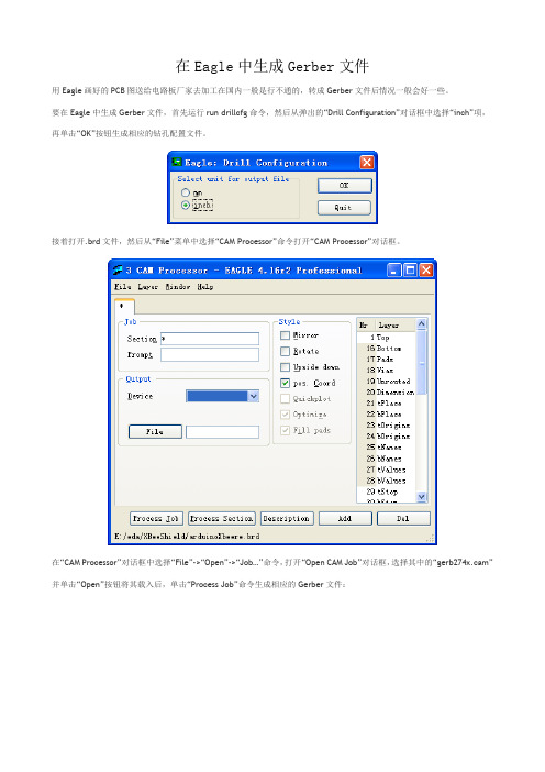
要在Eagle中生成Gerber文件,首先运行run drillcfg命令,然后从弹出的“Drill Configuration”对话框中选择“inch”项,再单击“OK”按钮生成相应的钻孔配置文件。
接着打开.brd文件,然后从“File”菜单中选择“CAM Processor”命令打开“CAM Processor”对话框。
在“CAM Processor”对话框中选择“File”->“Open”->“Job…”命令,打开“Open CAM Job”对话框,选择其中的“gerb274x.cam”并单击“Open”按钮将其载入后,单击“Process Job”命令生成相应的Gerber文件:
再在“CAM Processor”对话框中选择“File”->“Open”->“Job…”命令,打开“Open CAM Job”对话框,选择其中的“excellon.cam”并单击“Open”按钮将其载入后,单击“Process Job”命令生成相应的钻孔文件:
在完成上述步骤之后,在你的.brd文件所在的目录下面会生成其他一些文件,这些就是可以送去做电路板的Gerber文件,前提当然是你送去的厂家接受这种格式的文件才可以:-)。
DXP,生成Gerber文件
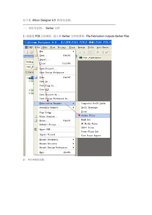
以下是Altium Designer 6.9 的导出过程:-----------------------------------------------------------------------------------------------一、导信号层的:Gerber文件1)前提是PCB已经画好,进入导Gerber文件的菜单:File-Fabrication Outputs-Gerber Files2)单位和精度设置:在“一般” 里面,“单位”选择“英寸”,格式请选择2:4 ,这个尺寸精度为中(2:3 低,2:4 中,2:5 高),当然,也要先和制板加工厂协商确定精度。
一般默认选择:2:4 就可以了.--------------------------------------------------------------------------------------3) 选择已经使用的层进行导出:(也可以在Plot 中全部选定):把镜像的层,全部去除,不用选 .(4)在“Apertures”里面,选中“Embedded apertures(RS274X) ”(在方格里打勾) 。
(5)最后点击“OK“即可生成所需要的Gerber文件。
二、导钻孔文件。
“单位”选择“英寸”,格式请选择2:4 ,最后点击“OK“即可生成所需要的钻孔文件。
到这里,就完成了所有的GERBER 文件导出了。
gerber 后缀名介绍:gto : 顶层字符gts : 顶层阻焊gtl : 顶层线路gbl : 底层线路gbs : 底层阻焊gbo: 底层字符drl : 钻孔层gko: 禁止布线层(边框)gdd: 一般不用,是分孔图,用来标注和分辨孔的大小位置1. 为何要将PCB文件转换为GERBER文件和钻孔数据后交PCB厂制板大多数工程师都习惯于将PCB文件设计好后直接送PCB厂加工,而国际上比较流行的做法是将PCB文件转换为GERBER文件和钻孔数据后交PCB厂,为何要“多此一举”呢?因为电子工程师和PCB工程师对PCB的理解不一样,由PCB工厂转换出来的GERBER文件可能不是您所要的,如您在设计时将元件的参数都定义在PCB文件中,您又不想让这些参数显示在PCB成品上,您未作说明,PCB厂依葫芦画瓢将这些参数都留在了PCB成品上。
EAGLE文件资料转换成GERBER

Eagle导出Gerber的方法1.将需要解读的*.BRD文件放在一个文件夹,以项目名称命名.(因为Eagle导出Gerber时会将所有文件输出在源文件位置).B2.左键双击或者右键打开*.BRD文件,在已经安装程序中选择EAGLE软件打开.打开后界面如下:原始的*.BRD文件创建相应项目文件夹3. 检查文件的板层数,层压结构和设计信息.如下图:通常 PCB 设计人员会在Layers 中输入正确的数据,但不排除有遗漏,如发现与客户或其它指示有冲突,需与客户确认清楚;另外,如遇到FPC ,一般需要向客户索要叠层结构说明文件。
4.导出钻孔列表.在文件菜单下选择运行ULP.选择英制单位.钻孔刀序和孔显示.此处点击OK,自动保存在源文件位置.5.钻孔,线路,阻焊,字符和钢网等文件输出.钻孔导出:在文件菜单下选择CAM处理器.线路输出:提示缺失信号层,点OK即可此处所有层内容均为默认选择. 此处线路层需对应选择.补充:Gerber 文件说明:-----------------------------------------------------------*.GBL 底层铜箔*.GBO 底层丝印(本次,无)*.GBS 底层阻焊*.GTL 顶层铜箔*.GTO 顶层丝印*.GTS 顶层阻焊*.GML 特殊铣孔*.TXT 钻孔文件*.drl 钻具列表===========================================================辅助文件扩展名说明:-----------------------------------------------------------*.dri 钻台信息文件,用于 *.TXT。
辅助。
*.gpi 光绘信息文件,用于 *.GML。
辅助。
===========================================================特殊说明:-----------------------------------------------------------无===========================================================*************************************************************************** *********************/其中的辅助文件可以不发。
pcad软件转换Gerber方法

pcad软件转换Gerber方法How-To DocumentProcedure DescriptionGenerating of extended Gerber- and Excellon data with PCAD for CircuitCAM 4.x and 3.xRequirementsPCAD Accel CAD softwareCircuitCAM software Completed PCAD PCBProblem / Procedure SolutionYou will need a completed design in Accel PCB to work with. This example uses theTutor3 board in the Accel EDA tutorial.All the layers of the completed PCB design are listed in the center window marked Layers:. CircuitCAM only needs the Top, Bottom, and the Board Outline trace layers.Close this window with the button in the lower right corner.Closing each step of the Gerber File process in Accel EDA returns you to the File:Gerber Out window.Click on Apertures.. which is the second switch from the top. It is rarelynecessary to alter the aperture list from the defaults that are set up by the PCB design program. You would only do this if you are using a standard aperture list for all of the boards that are being made for a project or throughout the company. For this example, we assume that the aperture listing made by Accel EDA is OK. Therefore, all you need to do on this window, is click on the Auto Button in theThe next switch on the File:Gerber Outlist is the drill symbols.The last step in setting up each Gerber file, is to set the format for the X-Ycoordinate numbers . To save memory space, the decimal point was removed from all of the numbers in the Gerber format. The decimal must be reinserted into its correct location in order for the board image to be reproduced with the right scale. The numeric format, or digits m.n , in CircuitCAM, sets the decimal position from the beginning, or from the end of the number sequence of the X-Ycoordinates for the circuit elements. The lower switches instruct the PCB program to include the circuit element sizes and shapes in a header at the beginning of the Gerber file, in what is known as ’Embedded Apertures’.To actually create the files, click on the button marked Generate Output Files. Gerber files are all written in ASCII characters and can be viewed with any text editor, such as NotePad or UltraEdit.Creating the Excellon Drill File from a PCB design in Accel EDAThe Gerber file set contains the information for reproducing the image of the board traces and outline but these files do not have the locations and sizes of the drill holes. LPKF’s CircuitCAM program needs the drill pattern information in an NCD (Numerically Controlled Device) file. This format (also called Excellon after the company that created it), is much less complex than Gerber. In Accel EDA, making an NCD file is a separate process from making Gerbers.In the File N/C Drill dialog window, Click Generate OutputFiles and Close.Loading Accel Gerber and Excellon files into CircuitCAMCircuitCAM selects GerberX as the File-Type by opening the file and examining its structure. The apertures are read into a ‘format configuration ’, which is an internal structure to CircuitCAM, of the data needed, to make the image of the PCB. This format configuration will have a name that you enter in the Aperture List text box (third from the top). The other information, such as measure units and decimal position , is in the header of the Gerber file. Verify that the size of the board is correct. Also ensure that the Layer name is applicable to the file that you are importing. You can check the title bar at the very top of the window, for the extension of the Gerber file, to make sure that it matches the Layer name.The other two Gerber files for Bottom and Board layers are loaded in the same manner. Be sure to select the correct layer in CircuitCAM for each file. The drill layer gets imported the same way as the Gerber layers with one exception. Accel EDA defaults to 2.4 as the decimal position for NCD files and Circuit CAM defaults to 2.3.Load the NCD file into the DrillUnplated layer. Do not use the DrillPlated layer unless you will be making the PCB with LPKF’s AutoContact system for plating the drill holes. Having data in the DrillPlated layer, will force the creation of BoardMaster phases that are specifically designed for AutoContact use only. If you are using the LPKF MiniContac Electroplating system for thru-hole connection, then also place all NCD drill data into the DrillUnplated layer.The Accel demo will overlay the drill layer directly into correctposition onto the Gerber’s drill pads. However, it sometimes happens that there will be an offset between the drill pattern and the Gerber p attern. This results from the user’s having set a different zero reference point in the PCB layout program from the PCB program’s internal zero reference point. The Gerber’s get written from the user’s reference point and the NCD file gets referenced from the other internal default point.This is easy to fix in CCAM. First click on a pad for which you know the correct dot inthe drill pattern. Then click on the Make Zero Point icon. Now click the drill hole dot and click the Move Layer icon. This will shift the entire drill pattern into to the correct position over the pads.ReferencesCircuitCAM manualAccel PCAD manualLPKF Technical SupportAuthorCraig Kniskern。
Altium9生成gerber文件
Altium Designer Summer 09 Gerber文件设置编辑制作人:王千会 10/03/23Gerber文件是一种符合EIA标准,由GerberScientific公司定义用于驱动光绘机的文件。
该文件是把PCB图中的布线数据转换为光绘机用于生产1:1高精度胶片的光绘数据,能被光绘图机处理的文件格式。
PCB生产厂商用这种文件来进行PCB制作。
各种PCB设计软件都支持生成Gerber文件的功能,一般我们可把PCB文件直接交给PCB生产商,厂商会将其转换成Gerber格式。
而有经验的PCB设计者通常会将PCB文件按自己的要求生成Gerber文件,交给PCB厂制作,确保PCB制作出来的效果符合个人定制的设计要求。
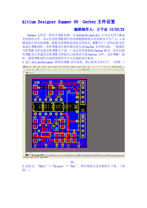
1.进入Altium Designer 软件的PCB 设计界面,然后将其文件打开。
(如图一)图一2.定原点:“Edit”→“Origin”→“Set”,然后将原点定在板的左下角。
(如图二)图二3.放置钻孔位图符号对应的孔大小的列表。
把PCB层切换到DrillDrawing层,然后用放置字符串的工具放置一个String: “Place”→“String”按快捷键P+S. 此时按tab键,在出现的text文本框中点击下拉箭头,在出现的序列中选择.Legend.点击OK。
(如图三)将其放在板外(图四)。
如果放置“.Legend”后,没有退出此操作,按下“Esc”键或鼠标右键即可。
图三图四按快捷键L,切换到View Options,如果用户误该动了系统默认设置,勾选了Convert SpecialString转换特殊字符串选项(如图五)字符串就会显示(如图六)所示;但这并不影响钻孔视图列表的生成。
图五图六放置钻孔位图符号一定要放在“DrillDrawing”层,尽量放在PCB的右下角,因为在导入CAM350里面的时候钻孔列表是从左下方起始向右上方拓展的。
(如图七)图七4.转Gerber:在PCB编辑器的主菜单中选择“File”→“Fabrication Output”→ Gerber Files命令(如图八)。
输出gerber文件步骤

嗯这方面我自己也不是很懂,参考了这个网址的介绍。
这里针对的是一般情况下、没有盲孔的板子。
1、首先是生成Gerber Files:打开PC B文件,在DXP2004中选择菜单File-Fabrication Outputs-Gerber Files,进入生成Gerber文件的设置对话框。
·单位选择英寸,格式选择2:5这样可以支持的精度会高一些(这些也可以先跟制板厂联系一下确认)·在Layers中,选中“inc lude unc onnec ted mid-layer pads”,同时Plot Layers选择A ll Used Mirror Layers全都不选,然后在右侧选中相关的机械层。
·Drill Drawing中什么都不选,保持默认即可。
·在A pertures中,选择E mbedded apertures(RS274X)·A dvanced中其余项都保持默认,主要是选择“Suppress leading zeroes”(此项也可与制板厂联系确认)·点击确认,会自动生成Gerber文件,此时生成一个c am文件,此文件可以不保存,因为我们要交制板厂的文件已经在项目的目录里面建了个子目录叫作“P rojec t O utputs for xxx”,各个层的gerber都存在里面了。
2、然后是生成NC Drill F iles:·同样,在DXP2004中选择菜单File-Fabric ation O utputs-NC Drill Files,进入生成NC Drill文件的设置对话框此处的选择要跟前面Gerber文件中的保持一致:英寸-2:5-Suppress leading zeroes其它选项保持默认,点击O K确认一下随后弹出的钻孔数据对话框,然后就会自动生成NC Drill Files了,同样的,生成的文件会在那个子目录里,而CAM文件可以不用保存3、将含有以上生成的文件的那个子目录“Project Outputs f or xxx”,打个包,就可以发给制板厂了,呵呵。
常用多种CAD软件转换GERBER的方法及技巧
序 言将客户原始文件转换为GERBER 文件是电路板厂的制前工程师必定的程序,但如何保证转换后的GERBER 文件与客户的设计意图一致?如果转换的GERBER 文件错了,不论您怎么处理,做出来的PCB 仍然是错误的。
所以,在转换GERBER 这一步骤绝对不允许出错,否则以后的工作会白费工夫。
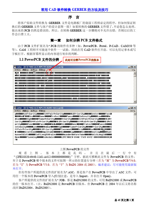
第一章 如何分辨PCB 文件格式由于PCB 文件扩展名为*.PCB 的软件有多种(如:PowerPCB 、Protel 、P-CAD 、CAM350等等),CAM 工程师不可能逐个软件一一试验,因此在用CAD 软件打开前,可以先用记事本或写字板打开,根据屏幕所显示的内容进行初步的判断。
1.1 PowerPCB上图PowerPCB 的文件观看上图,基本上都是乱码,并且在最后一行中有“{2FE18320-6448-11d1-A412-000000000000}”字样,据此可推断此文件为PowerPCB 的文件;至于是PowerPCB 哪个版本的文件可按图一所示的位置进行分辨(若为“H ”为PowerPCB V4.0,若为“I ”为PowerPCB V5.0,若为“J ”为PADS 2004或2005),编者建议:尽可能使用最新版本打开。
但有些客户所提供的文件的扩展名为*.ASC ,那是客户在PowerPCB 中导出了ASC 文件,可用任一个版本的PowerPCB 导入(特别注意:是导入Import ,并非打开Open)。
客户所提供的文件的扩展名为*.JOB ,那是PADS2000的文件,可用PADS2000或PowerPCB 的任一版本打开。
(注:PADS2000是PowerPCB 旧版本,但PowerPCB 在2004年以后又将名称改回PADS2004、PADS2005)。
1.2 Protel文件的分辨上图为PROTEL V2.8的文件观看上图,在第一行中有“PCB FILE 6 VERSION 2.80”字样,由此推断此文件是Protel V2.8的文件,可用Protel V2.5、Protel V2.8、Protel 98、Protel 99SE、Protel DXP或以上新版本打开。
Eagle5.11 PCB生成Gerber方法

Eagle 5.11.0 PCB文件输出Gerber文件方法作者:孙民强QQ:623322396 Email:summer13765@ 本文以Eagle软件中自带的文件“singlesided.brd”为例做讲解,此“X:\Eagle5.11.0\projects\examples\singlesided ”,文件的放置目录是:X是你安装Eagle的盘符。
原文件没有走线,我重新布局,添加了几个器件,并且将部分器件换成了SMD封装,改变了放置层面,目的是能做清晰明了的说明。
1.打开需输出Gerber文件的PCB图。
2.执行“RUN”命令,并执行“drillcfg.ulp”,生成钻具列表。
3.运行CAM管理器。
4.点击“文件—打开—作业”,选择“Sun.cam”文件,并点击打开。
5.点击“处理作业”,便可自动生成输出所有的Gerber文件。
如果点击“处理”,则只输出当前选项卡对应的文件,每个选项卡都需要单独点击才能输出完整的Gerber文件。
6.Gerber文件自动保存到PCB文件目录下。
共11个文件。
各个文件说明如下:XXX.DRL:钻具列表XXX.CMP:元件层(顶层)文件XXX.SOL:焊接层(底层)文件XXX.PLC:顶层丝印文件XXX.PLS:底层丝印文件XXX.STC:顶层阻焊层文件(过孔阻焊)XXX.STS:底层阻焊层文件(过孔阻焊)XXX.MEL:机械层文件(机械外形和铣削加工)XXX.TXT:钻孔坐标文件XXX.DRD:钻孔列表文件XXX.DRI:钻孔信息文件XXX.GPI:信息文件XXX.DRI文件和XXX.GPI可以不发给制板厂,也可以删除。
7.用CAM350查看刚才输出的Gerber文件。
运行CAM350,点击“File—Import—Auto Import”,选择你所输出Gerber文件的路径,并点击“Next”。
选择钻孔坐标文件项,点击“Excellon”项,将Decimal项选为4,点击“OK”,再点击“Finish”。
gerber转换
PROTEL99SE将PCB格式转为GERBER格式及钻带文件<1>转GERBER格式:从“File/CAM Manager”→在“Output Wizard”窗口点击最下端的“NEXT”→在“What kind of output do you want to make?”的询问框下选择“Gerber”后点击最下端的“NEXT”→在“What name do you want to give to thisgerber output?”在框中给要输出的Gerber文命个名(也可用电脑的默认名)后,点击最下端的“NEXT”→“How apertures are handled”的框下,点击最下端的“NEXT”→选择输出单位及格式(一般选“Inches”和“2:5”格式)后,点击最下端的“NEXT”→输出层及镜像层选择(输出选择层点击“Menu/Plotlayers/Used on”;镜像层全不选:“Menu/Mirror Layers/All off”)后,点击最下端的“NEXT”→在“Do you want to generate any drill drawing plots?下,将两项都选定后,点击最下端的“NEXT”→再选择“Plot used drill drawing lay与Graphicsymbol”,并将“Symbol”栏改为“80mil或2mm”后,点击最上端的“NEXT→”再次点击最下端的“Next”→最后点击向导完成提示界面最下端的“Finish”,Gerber文件即转换完成。
<2>转钻带文件:Gerber文件转换完成后,电脑自动弹出“CAM Output for *.CAM”的界面。
此时,在菜单“Tools”下点击“Output Wizard”→在“Output Wizard”窗口点击最下端的“NEXT”,在“What kind of output do you want to make?”的询问框下选择“NC Drill”后,点击最下端的“NEXT”→在“What is the name forthis NC drill output?”的框中给要输出的钻带文件命个名(也可用电脑的默认名)后,点最下端的“NEXT”→选择输出单位及格式(一般选“Inches、2:4格式)后,点击最下端的“NEXT”→最后点击向导完成提示界面最下端的“Finish”,钻带文件即转换完成。
PCB常用软件文件转换成GERBER方法(CAM工程师)
PCB常⽤软件⽂件转换成GERBER⽅法(CAM⼯程师)常⽤CAD软件转换Gerber的⽅法及技巧序⾔将客户的原始⽂件转换为Gerber⽂件,是线路板制前⼯程师必定的程序。
但如何保证转换过的Gerber⽂件与客户的设计意图⼀致?如果转换的gerber⽂件错了,⽆论你怎么处理,做出来的⽂件都是错误的。
所以,在转换⽂件这⼀步,绝对不允许出错,否则以后的⼯作会⽩废功夫。
第⼀章如何分辨PCB的⽂件格式由于PCB⽂件的扩展名为*.pcb的软件有很多种。
⽐如:power pcb、protel99、p-cad、cam350等,CAM⼯程师不可能逐个软件⼀⼀试验。
因此在⽤CAD软件打开前,可以先⽤记事本或Total Commander(⽂件管理器)打开,根据屏幕所显⽰的内容进⾏初步判断。
1.1 power pcb⽂件的分辨当我们打开⽂件后,发现基本上是乱码,并且在最后⼀⾏是{2FE18320-6448-11d1-A412-000000000000}字样,有此推断,这个⽂件是powerpcb设计的。
⾄于是那个版本,我们可以在⽂件的开头位置进⾏分辨。
“H”表⽰4.0;“I”表⽰5.0;“J”表⽰2004或者2005设计的。
笔者建议,尽可能使⽤最新版本打开客户⽂件。
1.2Protel⽂件的分辨在⽂件的开头有PCB file 6 Version2.8字样,我们可以推断是P rotel2.8版本设计。
那么,我们可以⽤P rotel 2.8、Protel98、P rotel99se、DXP2004打开⽂件。
如果,我们看到PCB4.0 Binary File字样,可以推断是99se的软件设计的。
可以⽤P rotel99se、DXP2004等⾼版本软件去打开,切忌不能⽤P rotel2.5、P rotel2.8、P rotel98这些低版本软件来打开。
1.3CAM350⽂件的分辨在⽂件的开头有Version8.6.2或者Version9.0的字样,我们可以推断是CAM350软件所设计。
GERBER简介、命令与格式转换
GERBER简介、命令与格式转换1.GERBER介绍1.1. Gerber的作用Gerber格式是线路板行业软件描述线路板(线路层、阻焊层、字符层等)图像及钻、铣数据的文档格式集合。
它是线路板行业图像转换的标准格式。
不管你的设计软件如何强大,你都必须最终创建Gerber格式的光绘文件才能光绘胶片。
早期的光绘机是由精确的伺服系统及受它控制的用来装高对比度胶片的X-Y 桌面组成的。
一个很亮的光源直透过快门,透过光圈,聚焦在胶片上。
控制系统把Gerber 命令成适当的桌面移动、轮子的转动和快门的开闭。
当快门打开,光柱透过光圈把光圈的影像暴光在胶片上。
当快门打开、桌面同步移动时,线条或条纹被影像到胶片上。
使用正确的命令控制桌面的移动、光圈的选择和快门的操作,光绘机就能在胶片上生成任何需要的影像。
Gerber Scientific (现在的Gerber 系统)开始通过生产精密的机器来控制光绘机工业。
“Gerber”这个词在光绘业已经名不副实。
1.2. Gerbr的分类现存Gerber有两个版本:扩展Gerber即RS-274X,被普遍使用;标准Gerber即RS-274D,是老版本,正逐渐被废弃并被RS-274X所取代。
RS-274XRS-274X(又称扩展的Gerber格式,或者X-Gerber格式)是二维矢量图像描述格式,也是线路板行业图像描述的标准格式。
RS-274X是一种可读的ASCII 格式,包含了一系列控制码和坐标信息,组成图像的元素是在特定位置画好外形的线和flash。
正性和负性图形对象可以组合。
RS-274X文档包含了线路板各层图像的完整描述,具有线路板图形成像需要的所有元素,不需要扩展文件。
Aperture可以定义正性物件和负性物件。
铜皮不需要像在RS-274-D中那样指定为"填充块"或者"填充线"。
RS-274X 是对线路板各层的完整、强大、清晰的标准描述,能被自动导入及处理。
Eagle双面板生成Gerber文件操作步骤

软件自带的示例文件为例)。如图—1
图—1 3. 生成钻具列表
点击“File”执行“Run”命令(也可以直接用鼠标点击工具栏上 的“ulp”图标)。在打开的对话框中选“drillcfg.ulp”并点击“打
图—8 5. 生成层输出文件 接上一步,在 CAM Processor 界面点击“File”,“Open”,“JOB”。在 打开的对话框中选“Sun”,点ss Job”生成层输出文件。
6. 输出文件说明
输出的所有文件与源文件在同一文件夹下。
xxx.cmp
图—4
图—5
3
4. 生成钻孔文件 点击“File”执行“CAM Processor”命令(也可以直接用鼠标点击 工具栏上的“CAM”图标)。如图—6
图—6 在 CAM Processor 界面点击“File”,“Open”,“JOB”。如图—7
图—7
4
在打开的对话框中选“Drill”,点击“打开”如图—8,再点击“Process Job”生成钻孔文件。
1
开”。如图—2
图—2 然后在弹出的对话框中选择“mm”或“inch”(此为钻头直径,依 据制板厂而定),并点击“OK”。如图—3
图—3
2
接下来显示的是钻头列表内容,我们不去管它直接点击“OK”即 可,然后弹出的是保存钻具列表对话框,在此我们也不要更改任 何内容直接确定即可(如果你要更改文件保存路径,那么你在生 成其他的文件时最好保持文件保存路径的统一)。如图—4、图—5
元件面
xxx.sol
焊接面
xxx.stc
元件面阻焊
EAGLE转Protel文件

EAGLE转Protel文件
原文链接:/stone1018/blog/11-12/236214_64b71.html
Arduino诞生在意大利,其电路设计软件、程序开发和国内大不相同。
因为开源所以给大家设计、参考带来了很大的方便,你可以直接下载其电路原理图、PCB、开发环境源码等等一堆资料。
但是它的电路设计软件采用国外比较流行的EAGLE设计软件,在国内并不常用,自己研究了一下文件格式的转换,可以转换为protel支持的文件格式。
步骤如下。
EAGLE官网
打开arduino源文件
下载原理图和PCB转换“用户语言程序”,以PCB为例,链接
PCB:export-protelpcb.ulp;export-protelpcb4layer.ulp(四层板)
SCH:eagle2ad_sch.ulp
转换,印制板图中,选择ULP
运行下载到的ULP
结果
至此,转换结束,可以用PROTEL 99SE/Altium打开转换好后的文件。
- 1、下载文档前请自行甄别文档内容的完整性,平台不提供额外的编辑、内容补充、找答案等附加服务。
- 2、"仅部分预览"的文档,不可在线预览部分如存在完整性等问题,可反馈申请退款(可完整预览的文档不适用该条件!)。
- 3、如文档侵犯您的权益,请联系客服反馈,我们会尽快为您处理(人工客服工作时间:9:00-18:30)。
Eagle导出Gerber的方法
1.将需要解读的*.BRD文件放在一个文件夹内,以项目名称命名.(因为Eagle导出
Gerber时会将所有文件输出在源文件位置).
B
2.左键双击或者右键打开*.BRD文件,在已经安装程序中选择EAGLE软件打开.打开后
界面如下:
原始的*.BRD文件创建相应项目文件夹
3. 检查文件的板层数,层压结构和设计信息.如下图:
通常 PCB 设计人员会在Layers 中输入正确的数据,但不排除有遗漏,如发现与客户邮件或其它指示有冲突,需与客户确认清楚;另外,如遇到FPC ,一般需要向客户索要叠层结构说明文件。
4.导出钻孔列表.
在文件菜单下选择运行ULP.
选择英制单位.
钻孔刀序和孔显示.此
处点击OK,自动保存
在源文件位置.
5.钻孔,线路,阻焊,字符和钢网等文件输出.
钻孔导出:
在文件菜单下选择CAM处理器.
线路输出:
提示缺失信号层,点OK即可
此处所有层内容均为默认选择. 此处线路层需对应选择.
补充:
Gerber 文件说明:
-----------------------------------------------------------
*.GBL 底层铜箔
*.GBO 底层丝印(本次,无)
*.GBS 底层阻焊
*.GTL 顶层铜箔
*.GTO 顶层丝印
*.GTS 顶层阻焊
*.GML 特殊铣孔
*.TXT 钻孔文件
*.drl 钻具列表
===========================================================
辅助文件扩展名说明:
-----------------------------------------------------------
*.dri 钻台信息文件,用于 *.TXT。
辅助。
*.gpi光绘信息文件,用于 *.GML。
辅助。
===========================================================
特殊说明:
-----------------------------------------------------------
无
===========================================================
*************************************************************************** *********************/
其中的辅助文件可以不发。
* 号用你自己的文件名替换。
